pool and spa heat pump owner™s manual
TRANSCRIPT

1
ATTENTION INSTALLER:THIS DOCUMENT IS PURCHASER’S PROPERTY AND IS TO REMAIN WITH THE HEAT PUMP OWNER
Models:T65T115T135
Pool and SpaHeat Pump
Owner’s Manual and
Installation GuidePN: LTP0009 01/12/04
1/7/04
(Also Applies to All C115 Models)

2
NOTES___________________________________________________________________________________
__________________________________________________________________________________
___________________________________________________________________________________
_________________________________________________________________________________
_________________________________________________________________________________
_________________________________________________________________________________
___________________________________________________________________________________
__________________________________________________________________________________
___________________________________________________________________________________
_________________________________________________________________________________
__________________________________________________________________________________
________________________________________________________________________________________
___________________________________________________________________________________
____________________________________________________________________________________
_________________________________________________________________________________
__________________________________________________________________________________
_________________________________________________________________________________
__________________________________________________________________________________
__________________________________________________________________________________
1-800-786-7751

3
TABLE OF CONTENTS
WELCOME TO THE TEAM------------------------------------------------------------------ 4IMPORTANT FEATURES OF YOUR NEW HEAT PUMP -------------------------------- 5SAFETY INFORMATION --------------------------------------------------------------------- 6QUICK START & STOP ----------------------------------------------------------------------- 8PHYSICAL CHARACTERISTICS & PERFORMANCE ----------------------------------- 9 Dimensional Information - TropiCal Models T65 and T115 --------------------------- 9 Dimensional Information - TropiCal Model T135 -------------------------------------- 10 TropiCal: Table of Specifications--------------------------------------------------------- 11 Refrigerant Circuit Performance Charts ------------------------------------------------- 11 Guide: Troubleshooting Refrigerant Circuit Problems --------------------------------- 13INSTALLATION -------------------------------------------------------------------------------- 14 Placement of Heater ------------------------------------------------------------------------- 14 Plumbing Requirements--------------------------------------------------------------------- 16 Electrical Requirements -------------------------------------------------------------------- 18START-UP & OPERATION ------------------------------------------------------------------- 20 Overview of Controls------------------------------------------------------------------------ 21 Initial Start-up and Basic Operation ------------------------------------------------------- 21 Heating Tips ---------------------------------------------------------------------------------- 22 Calculating Initial Heating Time ----------------------------------------------------------- 23MAINTENANCE ------------------------------------------------------------------------------- 24 Planned Maintenance ----------------------------------------------------------------------- 25 General Maintenance ----------------------------------------------------------------------- 25 Maintaining Proper Water Flow ----------------------------------------------------------- 26 Maintaining Proper Clearances Around Heater ------------------------------------------ 27SEASONAL USE & SHUT DOWN ---------------------------------------------------------- 27 During the Swim Season -------------------------------------------------------------------- 27 Freeze protection / Extended Shut Downs ------------------------------------------------ 27 Winterizing (Hard Freeze Conditions) --------------------------------------------------- 27TROUBLESHOOTING ------------------------------------------------------------------------ 29 Common Troubleshooting Issues ---------------------------------------------------------- 29 Troubleshooting Flow Charts --------------------------------------------------------------- 30REPLACEMENT PARTS --------------------------------------------------------------------- 34CONTACTING THE FACTORY -------------------------------------------------------------- 35

4
Welcome
eamT“You can rest assured
that your new heatpump is of the highestquality and efficiency,
and is designed andbuilt to provide years of
trouble-freeoperation.”
to the
Dear Owner:
Congratulations on your wise decision to make an AquaCal heat pump part of your home. Since1981, AquaCal has maintained the worldwide lead in the manufacture of swimming pool & spaheat pumps. Your new heat pump is not only a
great investment, but also the most cost effective methodavailable for heating pools and spas. For example, as ameans to heat pool or spa water, your heat pump is up to400% more efficient than gas, and, when compared toelectric resistance heat, your heat pump is nearly 600%more effective. You can rest assured that your new heatpump is of the highest quality and efficiency, and isdesigned and built to provide years of trouble-freeoperation. Moreover, should you decide you would likeAquaCal to provide regular inspection and maintenancefor your heat pump—which we do recommend—youwill find AquaCal has the largest and best-qualifiedservice staff in the pool & spa heat pump industry.

5
ThermoLink HeatExchanger:The heart of your heatpump is the patentedThermoLink heat ex-changer. The primarycause of prematureheat pump demise isthe failure of the heatexchanger. Ordinaryheat exchangers aremade from a cupron-ickel alloy. This cu-pronickel material issusceptible to attackfrom the sanitizers used in pools and spas, and fromother related water chemistry conditions. Once the heatexchanger fails, the heat pump is ruined. TheThermoLink heat exchanger tube is made from tita-nium, and is virtually impervious to water-chemistrydamage.
ElectronicController: State-of-the-art, solid-stateelectronic controller, main-tains water temperaturewithin 1ºF of set point. Con-troller also permits user topredefine different Pool andSpa water temperature setpoints.
Corrosion-ResistantCabinet:Hybrid design utilizes the best
features of finished aluminum and resilient ABS plas-tic. The base, being ABS material, will never rust orcorrode. The remainder of the cabinet is constructedfrom sturdy, marine-grade, powder-coated aluminum.
PLEASE SPEND A FEW MINUTES READING FURTHER TO BECOMEFAMILIAR WITH ALL THE FEATURES, THE SAFE OPERATION, AND THE
CARE OF YOUR NEW HEAT PUMP.
(135-Series)
IMPORTANT FEATURES OFYOUR NEW HEAT PUMP
ThermoLinkHeat Exchanger
Electronic Controller
Corrosion-ResistantCabinet
aaa

6
Used and maintained properly, your heat pump will provide year-upon-year of safe and economical service.However, as with any mechanical or electrical device, to get the most from your heat pump–while insuringpersonal safety for you and others–certain operational and maintenance factors must be observed.
Likewise, excepting a few minor owner-capable maintenance items (explained later in this manual), repair andservice of your heat pump must be performed only by experienced service personnel. Should you, the owner,suspect your heat pump is not performing properly, by referring to the section in this manual entitled:"Troubleshooting", you will be able to determine if a call for service is required. Your installer can be one sourceof service, or AquaCal Customer Support personnel stand ready to assist you at: (800) 786-7751. For questionsconcerning installation, modifications, operation, service and upkeep, please contact your installer or AquaCalCustomer Support. Warranties may be voided if the heater has been used, maintained, or repaired improperly.
In addition to possible voiding of warranties: unapproved installation methods, nonstandard modifications, poor orincorrect maintenance, service by unqualified personnel, or improper use of this unit, may result in personal injuryand/or property damage. For personal safety and to avoid damage to equipment, it is important that safetyinstructions displayed on the heat pump, and within this manual, are read, understood, and followed.
Throughout this manual the following two safety signals are placed where particular care is required. Please note"WARNING" relates to personal safety, while "CAUTION" signals promote avoiding damage to equipment.
SAFETY INFORMATION
This “Caution” symbol appears in this manual where special care is required to avoid equipment damage.
Failure to heed the following may result in damage to equipment.CAUTION !
Specific instructions will appear in this box.
Water Temperature Safety
WARNING ! Failure to heed the following may result in permanent injury ordeath.
Prolonged immersion in water warmer than normal body temperature may cause a condition known asHYPERTHERMIA. The symptoms of hyperthermia include: unawareness of impending hazard, failureto perceive heat, failure to recognize the need to exit the spa and unconsciousness. The use of alcohol,drugs, or medication can greatly increase the risk of fatal hyperthermia. In addition, persons having anadverse medical history, or pregnant women should consult a physician before using a hot tub or spa.Children and the extreme elderly should be supervised by a responsible adult.
This “Warning” symbol appears in this manual where special attention is required for personal safety.Specific instructions will appear in this box.
Failure to heed the following may result in permanent injury ordeath.WARNING !

7
Refrigerant Circuit Service Only byQualified, EPA Certified Technician
Heater NOT Repairable by Owner
WARNING ! Failure to heed the following may result in permanent injury ordeath.
Heat pumps contain no owner-repairable components. Repairs must not be attempted by untrainedand/or unqualified individuals. If service is deemed necessary, contact installing dealer or AquaCalCustomer Support at (800) 786-7751.
Water Chemistry Safety
Chlorine . . . . . . . . . . . . . . .:Bromine . . . . . . . . . . . . . . .:pH . . . . . . . . . . . . . . . . . . .:Total Alkalinity . . . . . . . . . .:Calcium Hardness . . . . . . . .:Total Dissolved Solids . . . . .:
1.0 – 3.0 ppm in pools, 1.5 – 3.0 ppm in spas2.0 – 4.0 ppm in pools, 3.0 – 5.0 ppm in spas7.4 – 7.6 ppm in pools, 7.2 – 7.8 ppm in spas80 – 140 ppm in pools, 80 – 120 ppm in spas200 – 400 ppm in pools and spas1,000 – 2,000 ppm in pools,1,500 ppm above start-up TDS in spas
RECOMMENDED WATER CHEMISTRY STANDARDS
While your heat pump’s titanium-based heat exchanger provides nearly impervious protection againstpoor water chemistry, improper water chemistry may cause expensive damage to pump, filter, poolshell, etc. To avoid equipment damage, maintain Pool-Spa water per standards below.
Failure to heed the following can result in damage to equipment.CAUTION !
Improper water chemistry can present a serious health hazard. To avoid possible hazards, maintainPool-Spa water per standards below.
Failure to heed the following may result in permanent injury ordeath.WARNING !
WARNING ! Failure to heed the following may result in permanent injury ordeath.
Heater contains refrigerant under high pressure. Repairs to the refrigerant circuit must not beattempted by untrained and/or unqualified individuals. Service must be performed only by qualifiedHVAC technicians. Recover refrigerant to relieve pressure before opening system.

8
This brief information is provided as an aide to installers, service personnel, and owners. The intent of thissection is to provide rapid access to (only) very basic operational information. Individuals who will beroutinely using, installing, maintaining and servicing this heat pump are strongly encouraged to read this
entire manual. If uncertain about any instructions given herein, AquaCal Customer Support (800-786-7751) shouldbe contacted for additional information.
How to Operate the Controls - Pool or Spa1. Turn the selected pool or spa thermostat dial clockwise to its highest setting.2. The heat pump will start and begin to heat the pool or spa.
NOTE: The heat pump has a time delay so if it shuts down for any reason, it will notrestart for approximately five (5) minutes.
3. The typical spa may take several hours to initially heat up, while a pool may take several days. Heatingtime will depend on the volume of water, water temperature, and the climatic conditions at the time ofstart-up. (Also see Calculating Initial Heating Time.)
4. When the pool or spa reaches the desired temperature, slowly rotate the thermostat knobcounterclockwise until the heat pump (just) stops. The thermostat is now set to automaticallymaintain this temperature.
QUICK START & STOP
Manual Switching From Pool to SpaNOTE: It is best to stop the pump while repositioning valves.
1. Open spa valves and close pool valves.2. With the spa filter pump running for at least five minutes, move the POOL/OFF/SPA toggle switch
from the Pool Setting to the Spa Setting.3. Turn the Spa thermostat clockwise until it stops (104 F).4. The typical spa may take several hours to initially heat up. Heating time all depends on the volume of
water, water temperature and the climatic conditions at the time of start-up.5. When the spa reaches the desired temperature (104 F is maximum), slowly rotate the thermostat
knob counterclockwise until the heat pump (just) stops. The spa thermostat is now set toautomatically maintain this temperature any time the spa thermostat has been selected.
Start Up1. Set pump controls to allow for temporary, continuous operation.2. With pump OFF, position water valves to heat the POOL or SPA.3. Rotate both thermostats counterclockwise to lowest temperature setting.4. Depending on valve settings (per #2, above), position the POOL/OFF/SPA toggle switch to point at
either the POOL or SPA thermostat knob.5. Ensure power is supplied to the heater, then start the water pump; the POWER and FLOW lights
should now both be lit. Permit the water pump to operate for five (5) minutes before proceeding
To Stop the Heat PumpThe unit can be stopped by switching off the electrical supply or by setting the desired temperature lowerthan the actual water temperature.
Time Clock ProgrammingOnce the heat pump has brought the pool or spa up to temperature, it will be necessary to reset the pumpcontrols. Be sure to allow enough running time for the heat pump to replace lost heat. This time will varydepending upon the time of year. Colder months require longer running times—usually eight to twelve hours.

9
PHYSICAL CHARACTERISTICS& PERFORMANCE
1. ALL DIMENSIONS IN INCHES2. MIN. CLEARANCE 24" FROM AIR COIL
BDATA PLATEINFORMATION
B
REAR VIEW
JK
H
POWER
OPTIONSBONDINGLUG
NOTES:
GF
ED
C
AIR COIL
A
CONTROL BOXACCESS PANEL
COMPRESSORACCESS PANEL
A
Dimensional Information - TropiCal ModelsT65 and T115

10
Dimensional Information - TropiCalModel T135
B
DATA PLATEINFORMATION
B
A
CONTROL BOXACCESS PANEL
COMPRESSORACCESS PANEL
1. ALL DIMENSIONS IN INCHES2. MIN. CLEARANCE 24" FROM AIR COIL
NOTES:
BONDING LUG
OPTIONS
POWER
H
KJ
ED
A

11
Refrigerant Circuit Performance Charts
Use of Charts- Information for the Technician:The charts are intended for use by trained and qualified air-conditioning and refrigeration technicians only.The charts are compiled specifically for evaluation and diagnostic purposes, and are NOT designed for useas charging charts. To apply the chart data to actual conditions: gather the operating pressures, suction tubesuperheat & liquid line subcooling values, water temperature change through the heater, and the total unitamps. Locate a chart that most closely represents current actual conditions. Readings obtained that differfrom the charts in excess of 10% (+ or -), may indicate a problem within the mechanical refrigerationsystem. Reference: Troubleshooting Refrigerant Circuit Problems, following the charts. Some interpolationbetween charts will be necessary should actual conditions not align reasonably well with the charts. Shouldrefrigerant circuit readings appear normal, but not the Water DT value, the likely cause will be water flowabove or below 45 GPM. (TropiCal refrigerant circuits will perform acceptably with condenser water flowbetween 20 to 70 GPM.)
Performance Charts Follow
TropiCal: Table of Specifications
�
MODELS: T65”X”-A T65”X”-B T115 “X”-A T115 “X”-B T135 “X”-A T135 “X”-B
BTU - 80%RH
Air ºF / Air ºF… 80/50 55000/37000 55000/37000 104,000/70,000 104,000/70,000 126,000/82000 126,000/82000
COP 4.8/3.7 4.8/3.7 4.3/3.2 4.3/3.2 5.7/4.0 5.7/4.0
BTU - 63% RH
Air ºF / Air ºF… 80/50 51000/34000 51000/34000 97,000/65,000 97,000/65,000 119000/77000 119000/77000
COP 4.5/3.6 4.5/3.6 4/3.1 4/3.1 5.4/3.8 5.4/3.8
Kilowatt Input (80% RH) 3.4 3.4 7.1 7.1 6.5 6.5
Voltage/Hz/Phase 208-230/60/1 208-230/60/3 208-230/60/1 208-230/60/3 208-230/60/1 208-230/60/3
Min. Circuit Ampacity 20.01 14.04 40.56 26.14 37.36 30.14
Recommended Fuse Size 20 15.00 40 30 40 35
Max. Fuse or Breaker Size 30 20.00 70 40 60 50
Min-Max Water Flow (gpm) 20-70 20-70 20-70 20-70 20-70 20-70
Shipping weight (lbs) 250 250 270 270 300 300
Shipping Size (l x w x h) 36" X 30" X 35" 36" X 30" X 35" 36" X 30" X 35" 36" X 30" X 35" 36"X30"X42 36"X30"X42
Uncrated Weight (lbs) 223 223 243 243 273 273
�
�
�
�
�

12
Refrigerant Circuit Performance Charts
For use with Troubleshooting Refrigerant Circuit Problems guide, following charts.�
��������������� ������������������������������������ !" �#�$��
�����������
��� �
��� �� �������
��� �������
�������
��� �������
�
���������������
����������
�����������������
���
������������
���
� ��� ! ���
��!"#$# %$#� &'(� (�� �)� �'� "�*� !"�
���"#$# %$#� &+"� (!� +� �(� ,�*� !&�
�)"#$# �%$#� &+,� +"� �"� �)� &�,� �+�
-.� ��/
�01�
�
������������������� ����������������������������������� !" �#�$��
�����������
��� �
��� �� �������
��� �������
���������� ��
�����
�
���������������
����������
�����������������
���
����������������
���
� ��� ! ���
��!"#$# �%$#� &**� '"� �(� �)� "�*� &+�
���"#$# �%$#� &&&� '(� �&� &*� ,�,� &(�
�)"#$# �%$#� &�)� +&� �)� �"� &�(� �'�
-.� ��/
�01�
�
%�&������������ ������������������������������������ !" �#�$��
�����������
��� �
��� �� �������
��� �������
���������� ��
�����
���������������
���
�����������������
���
����������������
���
� ��� ! ���
��!"#$# �%$#� �+(� ,&� �"� &"� !�,� &)�
���"#$# �%$#� &�,� ,+� "� &"� !�*� &"�
�)"#$# �%$#� &�&� "!� �!� &"� ��)� �"�
-.� ��/
�01�
�
$'(�$)*�+������������ �������������������������������������" �#�$��
�����������
��� �
��� �� �������
��� ����������������� ��
�����
�
���������������
����������
�����������������
���
����������������
���
� ��� ! ���
��!"#$# �%$#� &*�� (*� �(� �"� "�"� &+�
���"#$# �%$#� &&'� ()� �&� �+� ,�'� &+�
�)"#$# �%$#� &�+� +'� �'� �)� &�+� �'�
-.� ��/
�01�
�
�
�
�

13
NOTE: These guidelines are for use only by experienced, EPA certified, HVAC technicians, andwere developed specifically for use with AquaCal heat pumps, and for use with Refrigerant CircuitPerformance Charts contained earlier in this manual.
Possible Conditions:Unit Overcharged:• Head pressure will be above normal;• Suction pressure will be normal or slightly high (high, only if grossly overcharged);• Unit amperage will be somewhat high;• Liquid Sub-Cooling will be higher than normal;• Superheat will be normal to low (low, only if grossly overcharged).
Explanation: Excess liquid refrigerant backs up in the condenser (into discharge line if grosslyovercharged). Elevated head pressure & high liquid sub-cooling, with near-normal suction pressure andsuperheat, will be present. Unless grossly overcharged, the TXV will hold back the overcharge, maintainingnear normal suction pressure and superheat.
Unit Undercharged:• Head pressure will be below normal;• Suction pressure will be slightly low, to very low (depending on degree of undercharge);• Amperage will be low;• Liquid Sub-Cooling will be very low or nonexistent;• Superheat will be higher than normal.
Explanation: A full column of liquid may not be consistently present at the TXV inlet. This condition resultsin low suction pressure with higher than normal superheat. The liquid sub-cooling will be low, as will be thehead pressure.
TXV Stuck Closed:• Head pressure will be excessive;• Suction pressure will be lower than normal;• Amperage will be high;• Liquid Sub-Cooling will be higher than normal;• Superheat will be higher than normal;• Distributor lines may be frosted, iced, or very cold to touch.
Explanation: The flow of refrigerant is (mostly) stopped at the TXV. This results in a low suction readingwith high superheat. As liquid refrigerant “backs up” in the condenser, there is less room for high-pressurevapor coming from the compressor. Therefore, head pressure increases above normal (TropiCal models donot have sufficient space on the high-side to store the entire charge). With little refrigerant flowing, moreheat is being removed in the condenser than is being added at the evaporator- result: higher than normalliquid sub-cooling.
Guide: Troubleshooting Refrigerant Circuit Problems
Refrigerant Circuit Service Only by Qualified, EPA Certified Technician
WARNING ! Failure to heed the following may result in permanent injury ordeath.
Heater contains refrigerant under high pressure. Repairs to the refrigerant circuit must not beattempted by untrained and/or unqualified individuals. Service must be performed only by qualifiedHVAC technicians. Recover Refrigerant to relieve pressure before opening system.
14
TXV Stuck Open:• Head pressure will be slightly to moderately low;• Suction pressure will be slightly high to very high;• Amperage (not a reliable indicator of this condition);• Liquid Sub-Cooling will be lower than normal;• Superheat will be minimal or nonexistent;• Suction line, and possibly a large portion of compressor, will be very cold and possibly “sweating”.
Explanation: Refrigerant is flowing through the system too quickly; enough heat cannot be added in theevaporator to boil off all the liquid refrigerant. The main effect is to flood the suction line and compressorwith liquid refrigerant. The primary indicator of this condition is little or no suction line superheat. Also, asthe TXV is not holding back the required amount of refrigerant, there may be flash gas (high-pressurevapor) present in the liquid line; this is indicated by reduced liquid sub-cooling.
Insufficient Condenser Water Flow:• Head pressure will moderately high to very high;• Suction pressure my be normal to slightly high;• Amperage will be higher than normal;• Liquid Sub-Cooling will be absent; the liquid line will be very warm or even hot to touch. When combined
with high condenser water DT (see next bullet item), this condition is a prime indicator of insufficientcondenser water flow;
• Condenser entering-leaving water temperature difference (water DT) will be higher than normal… Thiscondition is a prime indicator of insufficient condenser water flow;
• Superheat will be high-normal to high.Explanation: Heat is not being removed in the condenser in quantities sufficient to produce appreciableamounts of liquid refrigerant. With no liquid seal occurring in the condenser, the liquid line–in essence–becomes an extended discharge line. Keys to diagnosis: very warm to hot liquid line, and a high condenserwater Delta-T.
Placement of Heater
Every indoor installation is unique, therefore, there are no specific guidelines for this type of installation. Forassistance, please contact AquaCal’s Engineering or Technical department at (800) 786-7751; they will assistyou with your specific needs.
Outdoor InstallationService and Operational Clearances:
Refer to recommended clearance drawings following this section. Allow 24" clearance between the heatcollection surfaces and walls, fences, shrubs, or other objects. The heat pump requires large volumes of airmoving over the heat collector.
Allow 5 feet of vertical clearance between the top of the heat pump and any roof overhang orother obstruction. This clearance prevents cold discharge air from recirculating back into the evaporatorcoils (recirculation would reduce the overall performance of the heat Pump).
Provide at least 30” open area in front of the main access panel. The electrical panel will need tobe accessed during installation and service, so avoid any plumbing obstructions that will restricteasy access.
INSTALLATION
Indoor Installation
u
u
u

15
Typical Installation Clearances
Code Required Clearances:In addition to the previously stated clearance requirements, follow all applicable local, state, and nationalrequirements relative to spacing from other objects or equipment.
u
24 - Inches(Side)
24 - Inches(Rear)
24 - Inches(Side)
30 - Inches(Front)
Front, Side and Rear
Rain run-off must be
directed away from unit
Overhang with gutter
5 ft. minimum clearance, overhead
2 ft. minimum clearance, rear
30” minimum clearance, front
(No Scale)
Front, Rear, and Overhead
Equipment Pad RequirementsThe equipment pad should be constructed to provide adequate drainage and support to the base of the heatpump (see Table below). The pad should be essentially level with just enough pitch to drain condensate andany other water away from the heater.
Anchoring Heater to PadFollow all relevant local, state, or national requirements regarding wind load anchoring (use huricane anchoringkit, part #STK0010). As necessary, contact AquaCal Technical Support, 800-786-7751, for assistance indetermining best method of compliance.
Irrigation, Rainwater Runoff, and Landscape Features
Place the heat pump away from rain runoff from the roof. A gutter or rain shield may be required on the roofedge above the heat pump.
Relocate or adjust irrigation to avoid water spray directly onto the heat pump. Do not locate plant shrubs orbushes directly adjacent to heat pumps. Doing so will prevent proper air circulation into the unit, and may inhibitaccess to the heater when service is needed. Consult drawings above for proper clearances.
Model Minimum Pad Size
T135
T115
T65
36” X 42”
36” X 42”
36” X 42”

16
Plumbing RequirementsOverview:
When planning plumbing system layout, reference the plumbing schematics following this section as a guide to thesequence of equipment, valves, fittings, etc. The plumbing configurations for typical installations are diagrammed.In operation, it is imperative the heat pump receive water flow within the minimum-maximum ranges specified forthe particular heat pump. Should the system installation under consideration not closely match any of the schematics,contact AquaCal Technical Support for advice and guidance: (800) 786-7751.
Minimum/Maximum Water Flow Rates:All TropiCal models are designed to operate successfully between flow rates of 20 to 70 gallons-per-minute(GPM) . Design the plumbing system to maintain at least 20 GPM flow through the heater; the heat pump will notoperate correctly, nor reliably, with less than 20 GPM of water flow supplied. If water flow rates through theheater will exceed 70 GPM, a spring-check bypass valve will be required; generally speaking, most residentialpools and spas will not require a bypass unless a pump of 2 HP or larger is used (for bypass valve details, seeinformation and plumbing schematic, following).
External Bypass Check Valve Requirement
For installations where flow rates exceed 70 gpm an additional spring bypass check valve must be installed.
NOTE:Use of the wrong size check valve may compromise the heat pump’s efficiency, reliability, and mayvoid the factory warranty. For models T135, T115 & T65, a 5 lb. Spring check valve is required.(AquaCal Part #2556.)
Parts and Materials:Industry technology changes much too rapidly for AquaCal to specify, with exactness, any items outside andbeyond the heat pump. What is specified is that the heat pump must be installed in accordance with all applicablelocal, state, or national codes & standards.
Connection to Heat Pump:All TropiCal heat pumps come equipped with 2" PVC, plumbing unions. Connection to site plumbing is made viaPVC solvent cement to the female slip socket of the plumbing unions.
Ability to Winterize:In regions where hard winters are typical, the unions mentioned above allow for easy disconnection/reconnectingof the heater from the plumbing system. Caution: do not defeat the function of the unions–use no glue on thethreaded portion of the unions.
Maximum Operating Pressure: 50 PSI
Bypass Check

17
Plumbing Schematics

18
Water IN & OUT Connections
For proper operation and maximum efficiency, piping coming from the pump and filter MUST be connected to the"IN" port of the heater. Likewise, connect piping returning to the pool/spa to the "OUT" port of the heater. Seedrawing below.
WARNING! Failure to heed the following may result in permanent injuryor death.
Installation made by unqualified persons can result in hazards to the installer and others. The informationcontained in this Electrical Installation section is intended for use by qualified electrical installation technicians,familiar with electrical service industry safety standards and methods. Electrical installation to be performedby qualified individuals only.
Electrical Requirements
General Information:u When possible, locate the equipment disconnect means within arm's reach of the heater's
electrical enclosure or as close as possible to the heater. Always satisfy applicable codes andstandards.
u All AquaCal heat pumps are designed for copper conductors, only. In sizing power wiring, beespecially aware of up-sizing requirements required due to wiring distances. Always satisfy
applicable codes and standards.u Multiple heaters installed at same site generally require special sequencing controls (AquaCal part
#ASC-(number of heaters)); if yours is a multi-heater installation, contact AquaCal Technical Supportfor assistance (800-786-7751).
u Electrical installation should be by licensed electrician only.u Connecting External Controllers: See document entitled “Connecting External Controllers to
AquaCal Heat Pumps”. These instructions are shipped inside heater accompanying the electricalschematic.
19
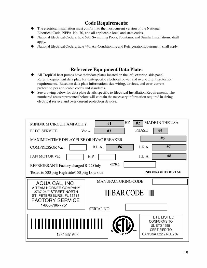
Code Requirements:u The electrical installation must conform to the most current version of the National
Electrical Code, NFPA No. 70, and all applicable local and state codes.u National Electrical Code, article 680; Swimming Pools, Fountains, and Similar Installations, shall
apply.u National Electrical Code, article 440, Air-Conditioning and Refrigeration Equipment, shall apply.
Reference Equipment Data Plate:u All TropiCal heat pumps have their data plates located on the left, exterior, side panel.
Refer to equipment data plate for unit-specific electrical power and over-current protectionrequirements. Based on data plate information; size wiring, devices, and over-currentprotection per applicable codes and standards.
u See drawing below for data plate details specific to Electrical Installation Requirements. Thenumbered areas represented below will contain the necessary information required in sizingelectrical service and over current protection devices.
MADE IN THE USA
PHASE
MAXIMUM TIME DELAY FUSE OR HVAC BREAKER
L.R.A.
FAN MOTOR Vac
REFRIGERANT: Factory charged R-22 Only
Tested to 500 psig High side/150 psig Low side INDOOR/OUTDOOR USE
AQUA CAL, INC A TEAM HORNER COMPANY 2737 24TH STREET NORTH ST. PETERSBURG, FL 33713 FACTORY SERVICE 1-800-786-7751
������������������������������������������������� � � � � � � � �
ETL LISTED �������� � � � � � � � �� � �
����������� � �� � � �� � � � �
��������� � � � �� �� � �� � �
� � � � � � � � �� �� � ��� � � �
MANUFACTURING CODE
SERIAL NO.
BAR CODE
#1 #2
#3 #4
#5
#6 #7
#8
MINIMUM CIRCUIT AMPACITY HZ
ELEC. SERVICE: Vac.~
COMPRESSOR Vac R.L.A
F.L.A. H.P.
oz/Kg

20
1. POOL TEMPERATURE CONTROL - Set this knob for desired pool water temperature
2. POOL/OFF/SPA -Toggles between pool temperature/off/spa temperature
3. SPA TEMPERATURE CONTROL - Set this knob for desired spa water temperature
4. POWER LIGHT - Indicates electrical power is supplied to the heater
5. FLOW LIGHT - Indicates water pressure (Flow) is present at the heater
6. DEFROST LIGHT - Indicates heater is in the defrost mode
T135/115/65 Control Panel Layout
Getting Familiar with Controls
START-UP & OPERATION

21
1. Lower Thermostat Settings-Set P/O/S Toggle Switch to OFF:u Turn both thermostat knobs counterclockwise to lowest settings.u Position the POOL/OFF/SPA toggle switch to "OFF".
2. Establish Water Flow and Electrical Power to the Heat Pump:u Position the water valves to heat either the pool or the spa.u Ensure any heat pump-related disconnect switches, or circuit breakers, are switched to the ON
position.u Start the pool or spa pump (depending of which body of water is to be heated), permitting the
pump to operate for a few minutes before going on to next step. This wait is necessary to clearany air that may exist in the water piping.
u The heat pump will not start without water flowing through it. At this point, the power and flow lights should be illuminated.
3. Select POOL or SPA-Raise Associated Thermostat:u Position the POOL/OFF/SPA toggle towards the POOL or SPA thermostat knob (depending
on which body of water you are preparing to heat).u Turn the selected pool or spa thermostat dial clockwise to its highest setting. As soon as the
thermostat setting is above the temperature of the water, the heat pump will begin to operate.
Initial Start-Up and Basic Operation(Please refer to "Overview of Controls", above, before continuing.)
POOL/OFF/SPA Toggle Switch:With the toggle switch in the OFF (O) position, the heater will be prevented from operating (however, there maybe power to the unit; see "Power Light On", below). With the toggle switch positioned toward the SPA or POOLthermostat knob, and with the following conditions met: 1) water pump in operation, 2) water flowing throughthe heater, and, 3) electrical power to the heater, the heater will run anytime the water temperature drops belowthe thermostat setting.
Power Light On:Indicates electrical power is supplied to the heater. The heat pump will start if the selected(POOL or SPA) thermostat calls for heat, and there is proper water flow through the heater.
Power Light Off:Indicates proper electrical power is not getting to the heater. If attempting to operate the heater,ensure any disconnect switches, or circuit breakers, are switched to the ON position.
Flow Light On:Indicates sufficient water flow to permit the heat pump to operate. The heat pump will startupon a call for heat from the selected POOL or SPA thermostat.
Overview of Controls(Please refer to control panel diagram on previous page.)
Note-Heater Can Start with Thermostats Set to Minimum:With proper water flow and electrical power supplied to the heater, and either the POOLor SPA thermostat selected and set to minimum, the heater will run any time the watertemperature falls below 60º F. To prevent the heater from operating at water temperaturesbelow 60º F, position the POOL/OFF/SPA toggle switch to the middle, OFF position.

22
4. Ensure Uninterrupted Pump Operation During Initial Warm-Up:u Permit your pool or spa circulation pump to run continuously until the desired water temperature is
reached. (with a pool, this may take several days.)u Continuous pump operation will likely require temporarily resetting (or removing completely)
the trippers on the time clock, thus allowing nonstop operation. When an external electroniccontroller operates pumps and valves, follow the controller manufacturer's instructions toensure temporary, uninterrupted pump operation.
u Throughout the warm-up period, keep the selected pool or spa thermostat dial set clockwiseto its highest setting.
5. Desired Water Temp. Reached-Set Thermostat to Maintain:u Once the desired water temperature has been achieved, rotate the thermostat knob very slowly
counterclockwise until the unit (just) shuts off.u The heater will automatically maintain your pool or spa at the selected temperature.
6. Return Pump Timer Controls to Normal Settings:u Reset pump timer controls for normal daily hours of operation.u During cooler or cold weather conditions, it may become necessary to extend the daily hours
of pump operation; doing so will help the heater to keep up with increased heat losses.u Also see next topic: "Heating Tips”
The heater controls contain a solid-state time delay module. This time delay feature preventsdamage to the compressor should electrical power be repeatedly interrupted, or if the heatpump were to come under any other circumstances leading to an on-off-on-off cycling condi-tion. If the heater has water flow and electrical power supplied, but the heater does not imme-diately start upon turning the thermostat to its highest setting, wait five (5) minutes; the timedelay module may be preventing the heater from operating. Likewise, once the heater isrunning, if the thermostat is turned back below the present water temperature, the heat pumpwill shut off. Subsequently, the heater cannot restart for approximately five (5) minutes, nomatter how far the thermostat is turned back up.
Note-Five (5) Minute Time Delay Function:
Heating Tips
A solar blanket will significantly reduce your heating bills. You should check with the installing dealer to see ifyour heat pump was sized to be used in conjunction with a solar blanket or without one. Blanketed pools willtypically lose only 3 - 4° of heat per night versus 8 - 10° overnight with an un-blanketed pool. Reductions of 40- 60% on heating bills can be achieved by using solar blankets.
Pool/Spa Blankets
Improperly used, Pool-Spa solar blankets can become a drowning risk to people and pets. Solar blanketsare not safety covers. They are not designed to support the weight of a person or pet. Never enter apool until the solar cover is completely removed (under no circumstances should anyone swim under theblanket). Follow all safety recommendations of the blanket manufacturer.
Failure to heed the following may result in permanent injury ordeath.WARNING !

23
Pool and Spa Combination HeatingEverything stated for heating a pool applies for heating a spa; only the volume of water being heated is different.TropiCal model heat pumps come equipped with two thermostats. One thermostat is for the pool and the other isfor the spa. Simply position the pool and spa isolation valves as directed by your installer; select the appropriatethermostat (pool or spa), whichever you are heating, and with electrical power and water flow supplied to theheater, the water will be maintained at set point.
Your system can be automated with the addition of an optional AquaCal Universal Heater Control (AquaCalpart #0097TS). This will save you from having to change the thermostat switch each time you change from poolto spa and back again. For details, contact your installing dealer.
Spa HeatingAir blowing into your spa while it is being heated will very often neutralize or partially counteract the heat beingput into the spa by the heater; this added heat loss equates to increased time to bring your spa to desiredtemperature. When heating a spa, be sure to turn off the air blower. Air induced through the spa jets should alsobe eliminated, during warm-up, whenever possible.
If your heater is being used to only heat a spa, the POOL thermostat can bet used as a set-back control: simplyset the pool control at a point 10-15º F below desired spa heat temperature, and select the pool thermostat. Thismethod allows the spa–when not in use– to be held at a heated temperature, but somewhat lower than normalspa-use temperature. One would want to blanket the spa if using this set-back method. This method will result inreduced warm up periods over full-cold start ups.
Heating in Cooler Weather (Defrost Cycle)When air temperatures drop below 50º F, your heat pump may go into a defrost cycle. The defrost cycle isinitiated by a sensor on the evaporator (air coil). When the evaporator temperatures fall to a point where icebegins to form on the fins, the heat pump will shut down. The heat pump will remain in the defrost mode until theevaporator coil temperature rises. In the event the air temperatures are below 40º F, the heat pump will remainin the defrost mode until temperatures rise above the 40º mark. The length of time the heat pump is in the defrostmode is dependent upon the air temperature: the warmer the air temperature, the shorter the defrost cycle; thecolder the air temperature, the longer the defrost cycle.
The need to defrost, is a very good reason why you should operate your heat pump only during the warmest partof the day. Late night and early morning is usually the coolest time of the day, and least efficient for heat pumpoperation.
Calculating Initial Heating TimeThe initial time it takes to get your pool warm depends on several factors. First you will need to determine howmany gallons of water are in your pool. If you know this, you can compute the pounds of water in the pool andthe BTU's necessary to heat the pool to the desired temperature. Secondly, you need to know the approximateBTU output of your heat pump at the ambient air temperature. Finally, you will need to determine the tempera-ture at which you plan to maintain your pool or spa.
Sounds complicated, but it's not! You can use the following worksheet to calculate approximately how long it willtake your heater to bring your pool up to temperature. Keep in mind that the time will vary somewhat due toweather conditions during the period that the heater is in use.

24
Volume of Pool (Length X Width X Average Depth) = _________ Pool Cubic Feet
X Gallons per cubic ft.(7.5) = _________ Pool Gallonage
X Pounds per Gallon (8.3) = _________ Pounds of Water
How many degrees do you want to raise the temperature of the pool?
# of Degrees _________ X Pounds of Water (per above) = __________ BTU’s Required
BTU’s Required (per above) ___________4 4 4 4 4 BTU Output of Heater = ______ Hrs. of Operation
Optional Cold Weather Adjustment Factor:
Hrs. of Operation (per above) ______ X 1.25 (60º F outside air (O.A.) Temperature Factor) = ______Hrs. of Operation at 60º F O.A.
When you start up your new AquaCal Heat Pump for the first time to heat your pool, you must allow the unit torun continuously until the desired temperature is reached. This may take from several hours to several daysdepending upon the time of the year and the outside conditions. If you utilize a time clock or similar device tocontrol the operating time of your pool system, you should temporarily override the device and allow it to run thepool or spa pump until the water reaches the desired temperature.
Your heat pump is a maintainer of heat and is sized to overcome the heat loss during the coldest period in whichyou are trying to heat. Once your pool is up to temperature, the time clock can be reset. The time your systemhas to run may need to be extended during the colder months when heat loss is at its greatest.
Since air is generally at its warmest during the day time, it is best to operate your heat pump during the daytimewhen there is more heat to transfer. So keep this in mind when you are trying to heat your pool.
NOTE: An optional Call Flex time clock manager (AquaCal part #0030S) can free you from having tochange the settings on your time clock as the heat loss increases or decreases. Contact your installingdealer for details.
The information in this section is written for the Home Owner, but also mayapply to a servicing dealer. The section contains information on planned main-
tenance, proper water flow, maintaining proper clearances as well as othervital information. Please read this section now, and before calling AquaCal
Customer Service at (800) 786-7751.
MAINTENANCE

25
Planned Maintenance ProgramJust as you would have yearly service performed on your air conditioning system, regular inspection &maintenance of your AquaCal heat pump will insure highest operating efficiencies while also protecting yourinvestment, potentially extending the useful life of your heat pump far beyond the warranty period. Ourexpertly trained factory service technicians offer comprehensive maintenance procedures that will insure yourheat pump operates efficiently and reliably when you need it to.
The 20-Point Planned Maintenance Service Includes the Following :
> Check Water Flow> Clean Evaporator Coil> Check Relay Contacts> Check Capacitor Values> Check Refrigerant Levels> Clean Heat Pump Cabinet> Check Fan Blade Clearances> Check Flow/Pressure Switch> Check Electrical Connections> Check Proper Voltage To Unit> Oil Fan Motor (As Applicable)> Check Fan Motor Amperage Draw> Check Pool & Spa Water Chemistry> Check and Clean Condensate Drains> Check Compressor Amperage Draw> Check Water Pump Amperage Draw> Acid Wash Source Coil (As Applicable)> Check Operating Controls and Temperature Sensors> Check Air Temperature Change Through Evaporator> Check Water Temperature Change Through Condenser
We recommend that all AquaCal heat pump owners take advantage of this annual service starting one yearafter the installation of the unit. You will be surprised at the minimal cost of this service. The service is veryreasonably priced for what is included. Please contact AquaCal Customer Support, at 1-800-786-7751, forfurther information or to schedule Planned Maintenance service.
General Maintenanceu You should have your heat pump inspected and maintained on an annual basis by a qualified pool
heat pump specialist. Additionally, if your heat pump is located on the beach, or at a sea wall wheresalt spray and sand can affect the unit, more frequent service may be necessary. For Service Planinformation, please see: Planned Maintenance Program, above, and then contact AquaCal Customer
Support at: 800-786-7751.
u While annual maintenance is recommended to maintain your warranty, if you choose not toparticipate in the Planned Maintenance Program, rinsing the air coil regularly, and keeping the baseof the unit clear of leaves and debris is a must.

26
u Control Irrigation: In regions were wells are used for irrigation, water quality is sometimes less thanpoor, and water spray can damage heater components. Regardless of water quality, it isrecommended that sprinklers be directed away from the heat pump.
u Prevent rain water run-off, from roofs, from pouring directly into the heater. The heater is designedto withstand normal rainfall, but solid streams of water from roof drip-lines may eventually damageheat pump components. If the heat pump resides beneath a roof edge, to promote heat pumplongevity, a rain leader (gutter) or rain shield will be necessary.
u Drainage: Your heat pump may produce abundant condensation under certain conditions; this isconsidered normal operation. Accordingly, keep the drain holes at the base of the heat pump freeof grass, weeds, dirt, or other obstructions, allowing for free and complete drainage around theheater.
u If the heat pump is located under trees, where leaves fall and accumulate in the bottom of the heatpump, a qualified technician should periodically remove accumulated leaves.
Do not use a pressure cleaner to wash heat pump . . . . Damage to evaporator fins, as well as othercomponents, will result.
Failure to heed the following may result in damage to equipment.CAUTION !
POSSIBLE ELECTRIC SHOCK HAZARD . . . Should you decide to wash the unit via water hose,disconnect all power to the pool equipment pad- including, but not limited to: The heat pump, water pump,and any and all other electrical equipment. Do NOT sprag water directly into electrical components. DoNOT restore electrical power until such time as all water has dried completely.
Failure to heed the following may result in permanent injury ordeath.WARNING !
Maintaining Proper Water Flowu It is important to operate and maintain the filter according to the manufacturer's specifications. As a
filter gets dirty, the water flow to the heat pump is reduced. The higher the pressure on the filter gauge,the lower the flow rate.
u Similar to a dirty filter, large amounts of debris in the pump basket can reduce water flow. Keepbasket free of debris.
u Check for improper valve settings. A partially closed valve after the filter, or a full-open bypass aroundthe heater, will cause insufficient water flow through the heater.
u If the conditions listed above remain unresolved, the water flow through the heater may be reduced to apoint where internal safety devices shut the heater off. Before calling for service, always check the filter,the pump basket, and water valve positions. If the problem persists, call AquaCal Customer Supportat: (800) 786-7751.
NOTE: During pool refinishing or acid washing, the water flow through the pool heater must be shut offuntil the process is completed, and the pool chemistry is once again in balance.

27
During the Swim Seasonu During the swim season, even if the pool or spa is not in use, allow water to flow through the heater.u This eliminates the need to reposition valves when you do wish to heat your pool or spa.
Freeze protection / Extended shut downsu In areas where freezing conditions are a rare occurrence, allow the filtration system to run continuously
through the freeze period. Typically, during light freeze conditions, circulating waterwill not freeze.
u In areas where freezing conditions are prevalent, please refer to winterizing instructions following thissection.
SEASONAL USE & SHUT DOWN
Failure to properly winterize unit may result in freeze damage to the heat pump. Freeze damage is notcovered under the unit warranty.
Failure to heed the following may result in damage to equipmentand/or property.CAUTION !
While the plumbing connections are in the winterized condition (not fully tightened), it is imperative pool-spawater not be circulated through the heat pump. Loss of water through loose plumbing connections mayresult in damage to circulating pump, pool-spa structure, and/or other equipment.
Failure to heed the following can result in damage to equipmentand/or property.CAUTION !
Winterizing (Hard Freeze Conditions)
Maintaining Proper Clearances Around Heateru For maximum efficiency, proper air flow clearances around heater must be maintained.
u It is important to keep the area around your heat pump clear of items such as shrubs and bushes, lawnfurniture, chemicals containers, etc. These items can prevent air from circulating properly through theheater, and will result in inefficient operation or damage to components inside the heat pump. Do notplace objects on top of the heat pump; doing so will block the air from exiting the heater, and will resultin damage to the compressor and fan motor.
u Proper clearances are also necessary in order to access the working parts of your heater. A heater thatis easy to "get to", will be a heater that is easy to maintain; service and maintenance personnel will thankyou for keeping the area around your heater unobstructed.
u Please see: Installation, Service, and Operational Clearances, for specific spacing requirements.

28
Winterizing Procedure:
1. Disconnect all electrical power to the heater; turn OFF circulating pump.2. At the two (2) water connection unions, disconnect the plumbing to the heater (removal is
counterclockwise).3. Locate the drain plug at lower, right-hand, front corner of heater. (See Figures 1 & 2, below.)4. Using a 5/8", box-end wrench, remove the drain plug (removal is counterclockwise).5. Permit all of the water to drain out of the condenser, and then replace the plug: thread the plug
in clockwise until just snug, then apply an additional 1/8 turn.6. To prevent insects and vermin from entering the plumbing during the winterized period, partially
reconnect the two (2) plumbing connection unions: couple each union one or two threads; thiswill permit condensation to drain, but will prevent most insects and animals from entering theplumbing circuit.
7. Next Season: to ready the heat pump for use, simply retighten plumbing connection unions.Hand-tight is generally sufficient.
FIGURE 1
FIGURE 2
Location of Winterizing Drain

29
Common Troubleshooting Issues
Heat Pump Not RunningIs the power light lit?
If not, ensure the main breaker (located at the power supply panel) and the disconnect switch(located near the heat pump) are both turned ON.
Is the flow light lit?If not , check to be sure that the circulating pump is operating and the filter is clean. There mayalso be a valve positioned incorrectly allowing water to bypass the heat pump. Be sure water isflowing through the heater.
Is the Pool or Spa thermostat selected, and have you tried turning the selected thermostat to a highertemperature setting?
If not, the actual water temperature may be above that of the selected thermostat. Raise thedesired water temperature above the actual water temperature; the unit should start after anapproximate 5-minute delay. If the heat pump still fails to start, and the unit is not in defrost (defrostlight lit), contact AquaCal Customer Support: 800-786-7751.
Please see Troubleshooting Flowcharts, following, for more detailed information.
Water Coming from the Heat PumpIs it a leak or just condensation from normal operation? Here's how to find out.
Shut off your heat pump, leaving the pool pump running. In a couple of hours there should be amarked reduction in the amount of water around the bottom of the heat pump. If the water appearsto be drying up, the water is probably harmless condensate.
Or, as an alternate method to check for a water leak, you can test the water draining out thebase for the presence of the sanitizer you are using in your pool or spa. Use your water test kit,or a test strip, to check a sample of the water for chlorine or bromine. If the sample tests positivefor sanitizer, call AquaCal for service at: 800-786-7751. If the test is negative, the water is probablyharmless condensate.
NOTE: If you are using an ionizer or ozone generator to produce sanitizer, this test method will not beeffective.
Heat Pump Running but Not HeatingIs the air blowing out of the top of the unit noticeably cooler than the surrounding air?
(A 9°F to 12°F difference is typical.) If not, call AquaCal for service at 800-786-7751.Be sure all air coil surfaces are free from obstructions; low roof overhangs, landscaping, walls,fences, etc., can restrict air flow. The heat pump needs good airflow to operate at peak efficiency.
How long are you running your circulating pump each day?Cooler weather conditions, or heating to a higher temperature, may necessitate running the heatpump for a longer period of time. A pool blanket can be useful in permitting shorter run times,in turn leading to substantial energy cost savings.
What is the air temperature?Your heat pump may be in the defrost mode if air temperatures are below 50°F. The defrostlight will be lit if the unit is defrosting. If air temperatures are not cold, but the defrost light isstill illuminated, contact AquaCal Customer Support at 800-786-7751.
TROUBLESHOOTING

30
STARTIs the thermostat turned UP,
and the toggle or rocker switch selecting either the
SPA or POOL thermostat ?
STARTIs the thermostat turned UP,
and the toggle or rocker switch selecting either the
SPA or POOL thermostat ?
Check to be sure thepower light is on. If thepower light is off, check
for a tripped circuitbreaker. Reset the
circuit breaker ifnecessary.
Check to be sure thepower light is on. If thepower light is off, check
for a tripped circuitbreaker. Reset the
circuit breaker ifnecessary.
Position controls toselect POOL or SPA;
rotate selectedthermostat to themaximum setting.
Position controls toselect POOL or SPA;
rotate selectedthermostat to themaximum setting.
Is the heateroperating correctly?
Is the heateroperating correctly?
Is the heater operating correctly?
Is the heater operating correctly?
Check to see that thepool pump is operatingand the flow light is on.
Make sure all watervalves are in the correct
position and the filterand pump basket are
clean.
Check to see that thepool pump is operatingand the flow light is on.
Make sure all watervalves are in the correct
position and the filterand pump basket are
clean.
The heater is equippedwith a five minute delay.
Wait at least fiveminutes to allow the
timer to reset.
The heater is equippedwith a five minute delay.
Wait at least fiveminutes to allow the
timer to reset.
ContactAquaCal for
Assistance at: 800-786-7751
ContactAquaCal for
Assistance at: 800-786-7751
ProblemSolved.
(Re-set thermastatsto desired
temperature)
ProblemSolved.
(Re-set thermastatsto desired
temperature)
Yes No
No
NoYes
Yes
Is the unit operatingcorrectly?
Is the unit operatingcorrectly?Yes
No
Troubleshooting Flow ChartsHeater Fails to Operate
Analog Controls - 12/22/03

31
STARTIs the air being discharged
out of the top of the heater 9-12degrees cooler than the
outside air?
STARTIs the air being discharged
out of the top of the heater 9-12degrees cooler than the
outside air?
Is the pool pump timerset to allow extended
operation of the heater?
Is the pool pump timerset to allow extended
operation of the heater?
Yes
Extend the pool pump'shours of operation to
accommodate additionalheater run time required
in cooler conditions.
Extend the pool pump'shours of operation to
accommodate additionalheater run time required
in cooler conditions.
Is the heaterperforming
adequately?
Is the heaterperforming
adequately?
ProblemSolved.
ProblemSolved.
No
Yes
Is the defrost light on, ordoes the display read : "FS" ?
Is the defrost light on, ordoes the display read : "FS" ?
No
Yes
The defrost light or "FS"displayed indicates air
temperature may be too lowto support the heater'soperation. Heater will
remain in defrost until airtemperature rises.
The defrost light or "FS"displayed indicates air
temperature may be too lowto support the heater'soperation. Heater will
remain in defrost until airtemperature rises.
Call AquaCal forAssistance:
800-786-7751.
Call AquaCal forAssistance:
800-786-7751.
No
Yes
No
Is the air Temp. above 40ºF (analog control)
or 38ºF (digital control)
?
Is the air Temp. above 40ºF (analog control)
or 38ºF (digital control)
?
Yes
No
ProblemSolved.
ProblemSolved.
Ambientconditions too coldto operate heater.
Ambientconditions too coldto operate heater.
Heater Running but Not HeatingAnalog or Digital Controls - 12/22/03

32
STARTIs the flow light on
and the unitheating?
STARTIs the flow light on
and the unitheating?
Call AquaCal forAssistance:
800-786-7751
Call AquaCal forAssistance:
800-786-7751
When the heater is operating,it is normal to produce up to 8
gallons of condensation (water)per hour. If water drainage
seems excessive, proceed toTESTING.
When the heater is operating,it is normal to produce up to 8
gallons of condensation (water)per hour. If water drainage
seems excessive, proceed toTESTING.
Yes
TESTING:If using chlorine as a pool/spa sanitizer, use a chlorinetest strip or test kit to determine whether the water is
from the pool or is normal condensation.OR
An alternative method of determining a pool water leak inthe heater is to turn the heater off for a few hours, leavethe pump running, and see if water continues to drain
from the heater.
Did the test resultsindicate the presence
of chlorine?
Did the test resultsindicate the presence
of chlorine?
Yes
Does water continueto drain from the heater
after the heater has beenoff for several hours?
Does water continueto drain from the heater
after the heater has beenoff for several hours?
Yes
This would indicatethe water present
is from normalcondensation.
This would indicatethe water present
is from normalcondensation.
No No
If heater has not run recently,and water is coming
from the heater, heater mayhave a water leak.
If heater has not run recently,and water is coming
from the heater, heater mayhave a water leak.
No
Chlorine Test Turn- Off Test
ProblemSolved.
ProblemSolved.
Determining Water Leaks vs. CondensationAll Analog/Digital Air Source Heat Pumps - 12/22/03

33
Heater Short CyclingAnalog Controls - 12/22/03
STARTIf the heater is turning on and
off every 5 minutes:Make sure all water valves arein the correct position, allowing
water to flow through theheater. Be sure filters andpump skimmer baskets areclean. Check to be sure thewater level in the pool is not
below the skimmer.
STARTIf the heater is turning on and
off every 5 minutes:Make sure all water valves arein the correct position, allowing
water to flow through theheater. Be sure filters andpump skimmer baskets areclean. Check to be sure thewater level in the pool is not
below the skimmer.
Is the flow light onand heater
operating correctly?
Is the flow light onand heater
operating correctly?
Is the flow light onand the heater
operating correctly?
Is the flow light onand the heater
operating correctly?
No
Problem Solved.Problem Solved.
Inspect water pressure switch fornormal operation; adjust
sensitivity if necessary .
* See DANGER statement.
Inspect water pressure switch fornormal operation; adjust
sensitivity if necessary .
* See DANGER statement.
Re-confirm that water is flowingthrough the heater...Check for
flow at Pool/Spa returns.
Re-confirm that water is flowingthrough the heater...Check for
flow at Pool/Spa returns.No
Heater operating correctly?
Heater operating correctly?
Is the fan operating?Is the fan operating?
No
Heater operating correctly?
Heater operating correctly?
Inspect the fan motor/capacitoras needed.
*See DANGER Statement
Inspect the fan motor/capacitoras needed.
*See DANGER Statement
Be sure the evaporator is cleanand free of air restricting
obstructions.
Be sure the evaporator is cleanand free of air restricting
obstructions.
No
Yes
Yes
NoCall AquaCal for Assistance:
800-786-7751
Call AquaCal for Assistance: 800-786-7751
Yes
Yes
Yes
������������������������
*Any operation described in thisflow chart, requiring the heater
access panel be removed,MUST be performed only byauthorized service personnel.

34
Effective 09/01/2003
To order replacement parts, contact AquaCal Customer Support: (800) 786-7751
REPLACEMENT PARTS
VOLTAGE : 1/60/208-230 VOLTAGE : 3/60/208-230 CONTROL BOX COMPONENTS T65”X”-A T115”X”-A T135”X”-A T65”X”-B 115”X”-B 135”X”-B
PART DESCRIPTION PART NUMBER PART NUMBER THERMOSTAT,HONEYWELL POTTED 6270 6270 6270 6270 6270 6270
THERMOSTAT, AMBIENT AIR (RANCO) 7048 7048 7048 7048 7048 7048
TIME DELAY, 5 MINUTE ON BREAK 6102A 6102A 6102A 6102A 6102A 6102A
TERMINAL BLOCK, 10 LUG WECO 6318 6318 6318 6318 6318 6318
TRANSFORMER, 208/240 - 24 50 VA. 6209 6209 6209 6209 6209 6209
CONTACTOR 6061 6061 61001 6147 6147 6147
CAPACITOR FAN 6051 6051 6051 6051 6051 6051
SWITCH, WATER PRESSURE SPDT 6248 6248 6248 6248 6248 6248
GROMMET, 7/8" BLACK PLASTIC 6022 6022 6022 6022 6022 6022
GROUND LUG, ADR-2 6020 6020 6020 6020 6020 6020
CONNECTOR,SOCK. HOUSING 20 PIN 6276 6276 6276 6276 6276 6276
CAPACITOR, RUN 6056 6057 60500 N/A N/A N/A
CONN. 1/2 ST. THRU LIQ. TIGH. HEYCO#3200 6701 6701 6701 6701 6701 6701
LOCKNUT, 1/2 BLK NYLON #NLN12B 9164 9164 9164 9164 9164 9164
TERMINAL BLOCK, 9 POLE WECO 6316 6316 6316 6316 6316 6316
PHASE ROTATION MONITOR N/A N/A N/A 6035 6035 6035
MAJOR COMPONETS VOLTAGE : 1/60/208-230 VOLTAGE : 3/60/208-230 T65”X”-A T115”X”-A T135”X”-A T65”X”-B 115”X”-B 135”X”-B
PART NUMBER PART NUMBER FAN GRILLE 7109 7109 7109 7109 7109 7109
FAN MOTOR 3114 3114 3114 3114 3114 3114
FAN BLADE 3104 3104 3104 3104 3104 3104
EVAPORATOR COIL ACP0001 ACP0001 ACP0006 ACP0001 ACP0001 ACP0006
CONTOL BOX PANEL ASSEMBLY HPA0015 HPA0015 HPA0015 HPA0015 HPA0015 HPA0015
TITANIUM COIL / HEADER FIELD KIT CDK0008 CDK0009 CDK0010 CDK0008 CDK0009 CDK0010
COMPRESSOR 4323 4623 4729 CR33KQ-TF5-240 4623-TF5 ZR81KC-
TF5-235 TSTAT SENSOR / WELL 6105D 6105D 6105D 6105D 6105D 6105D
TXV REP0007 REP0004 REP0005 REP0007 REP0004 REP0005
BASE-PLASTIC PCP0018 PCP0018 PCP0019 PCP0018 PCP0018 PCP0019
CONTROL PANEL HPA0007 HPA0007 HPA0007 HPA0007 HPA0007 HPA0007
FILTER DRIER 2036 2036 2036 2036 2036 2036
PLASTIC, 120 DEGREE COVER, BLACK PCP0005 PCP0005 N/A PCP0005 PCP0005 N/A
PLASTIC, 150 DEGREE COVER, BLACK PCP0004 PCP0004 N/A PCP0004 PCP0004 N/A
PLASTIC, 90 DEGREE COVER, BLACK 70100 70100 70100 70100 70100 70100

35
What We Need to Know When You Call UsIf you should need to call AquaCal for service, please have the following information ready:
Model: ________________________________
Serial Number: __________________________
Installation Date: ________________________
Having the above information ready will speed up the service process and allow us to respond more quickly.A brief description of what the unit is, or is not doing, will also help us to help you.
Please contact us at (800) 786-7751. We are here to serve you from 8 a.m. to 5 p.m. EST, Monday throughFriday. If calling after hours, our voice mail service will handle your call. Be sure to leave your name,complete address, and phone number.
If you prefer, you may FAX the information to: (727) 821-7471.
Thank You !
CONTACTING THE FACTORY

36
2737 24th St. NorthSt. Petersburg, FL 33713
1-800-786-7751