pool counterflow unit bga 160, bga 215, … · pool counterflow unit bga 160, bga 215, bga 275, bga...
TRANSCRIPT

POOL COUNTERFLOW UNIT BGA 160, BGA 215, BGA 275, BGA 320, BGA 430, BGA 550

BA-EN-HydroStar V3.1 page 1
Table of contents 1 Manufacturer's address.................................................................................................................... 1 2 General............................................................................................................................................. 2
2.1 Important information.................................................................................................................. 2 2.1.1 Technical data.................................................................................................................... 2 2.1.2 Information for the user / target group ............................................................................... 3 2.1.3 Hazard information ............................................................................................................ 4 2.1.4 Validity ............................................................................................................................... 4 2.1.5 Proper use ......................................................................................................................... 5 2.1.6 Operating conditions.......................................................................................................... 5 2.1.7 General safety and application notes ................................................................................ 6 2.1.8 Disposal ............................................................................................................................. 6 2.1.9 Scope of supply ................................................................................................................. 6
3 HydroStar installation shaft .............................................................................................................. 7 3.1 Scope of supply .......................................................................................................................... 7 3.2 BGA 160/215/275, installation in skimmer or overflow pools ..................................................... 7 3.3 BGA 320/430/550, installation in skimmer or overflow pools ..................................................... 8 3.4 Installing the spring-loaded flange.............................................................................................. 9 3.5 Aligning the turbine................................................................................................................... 10 3.6 Installation of the cover plate.................................................................................................... 10
4 Turbine without HydroStar installation shaft .................................................................................. 11 4.1 Installation example for a BGA turbine..................................................................................... 11 4.2 Dimensions of turbine BGA 160/320 with installation flange.................................................... 11 4.3 Dimensions of turbine BGA 215/430 with installation flange.................................................... 12 4.4 Dimensions of turbine BGA 275/550 with installation flange.................................................... 12
5 HydroStar BGA 160/320/275/550 C for retrofit installation ............................................................ 13 6 PIEZO Tri / PIEZO Tri Square, installation .................................................................................... 14 7 Control unit ..................................................................................................................................... 16
7.1 Connection block diagram........................................................................................................ 17 7.2 Terminals.................................................................................................................................. 17 7.3 Motor connection ...................................................................................................................... 18 7.4 Extending the motor supply line ............................................................................................... 18 7.5 Connecting the HydroStar PIEZO Tri ....................................................................................... 18 7.6 Connecting an external operating device ................................................................................. 19
7.6.1 Instructions for operation with a smartphone................................................................... 19 8 Start-up........................................................................................................................................... 19
8.1 Remote control operation ......................................................................................................... 19 8.1.1 Switching the turbine on and off ...................................................................................... 20 8.1.2 Water jet control............................................................................................................... 20
9 Optional operation by PIEZO Tri .................................................................................................... 21 10 Optional operation via touch display ........................................................................................ 22 11 End of operation ....................................................................................................................... 23 12 Shutdown / hibernation............................................................................................................. 23 13 Maintenance and repair............................................................................................................ 23
13.1 General................................................................................................................................. 23 13.1.1 Maintenance .................................................................................................................... 23 13.1.2 Repair .............................................................................................................................. 23 13.1.3 Troubleshooting ............................................................................................................... 24
14 Changes ................................................................................................................................... 24
1 Manufacturer's address BINDER GmbH & Co. KG Reichardstraße 16, D-31789 Hameln Tel. +49 (0)51 51/ 96 26 6-0 Fax. +49 (0)5151/ 96 26 6-49 Mail: [email protected] www.binder24.com

BA-EN-HydroStar V3.1 page 2
2 General
2.1 Important information Operation Guarantee
Observance of these operating instructions is essential to ensure trouble-free operation and in order for any warranty entitlements to be honoured. Therefore, please carefully read through the operating instructions before working with the counter current unit.
Intended use
The turbine swimming pool is intended for use in privately used swimming pools according to DIN EN 16582. It only be used in public swimming pools in special solutions.
Note
This operating manual includes instructions on storage, assembly, operation and maintenance of the HydroStar counterflow unit BGA 160, BGA 215, BGA 275, BGA 320, BGA 430 and BGA 550.
Start-up Maintenance Installation
The personnel entrusted with the handling, storage, installation, start-up, inspection and maintenance of the machine must be qualified for industrial, mechanical and electrical equipment.
Disposal
The current and regional regulations must be observed for disposal. Grease and oil must be disposed of in accordance with applicable environmental protection regulations.
Note
This device is not intended to be used by persons (including children) with limited physical, sensory or mental aptitude or lack of experience and/or knowledge unless they are supervised by a person responsible for their safety or have received instruction from this person as to how the device is used. Children should be supervised to ensure that they do not play with the device.
Danger If the mains connection cable for this device is damaged, it must be replaced by the manufacturer or its customer service department, or a similarly qualified person to prevent any hazard.
2.1.1 Technical data BGA 160 BGA 320 Supply voltage 230 VAC 230 VAC Frequency range 47 – 63 Hz 47 – 63 Hz Rated current 6 A 12 A Starting current (typical) 60 A 60 A Rated power 1350 VA 2700 VA Motor Motor type 1 Brushless DC motor
(BLDC) 2 Brushless DC motors
(BLDC) Rated voltage 24 VDC 24 VDC Rated current 50A 2 x 50A Rated rotational speed 2400 min-1 2400 min-1 Turbine Discharge rate 50 – 160 m³/h 100 – 320 m³/h Speed (turbine outlet) 1.0 – 3.2 m/s 1.0 – 3.2 m/s Water temperature +5° C to +40° C +5° C to +40° C Immersion depth 0.20 m – 1.00 m 0.20 m – 1.00 m

BA-EN-HydroStar V3.1 page 3
BGA 215 BGA 430 Supply voltage 230 VAC 230 VAC Frequency range 47 – 63 Hz 47 – 63 Hz Rated current 8 A 16 A Starting current (typical) 60 A 60 A Rated power 1500 VA 3000 VA Motor Motor type 1 Brushless DC motor
(BLDC) 2 Brushless DC motors
(BLDC) Rated voltage 24 VDC 24 VDC Rated current 40A 2 x 40A Rated rotational speed 2400 min-1 2400 min-1 Turbine Discharge rate 65 – 215 m³/h 130 – 430 m³/h Speed (turbine outlet) 1.0 – 3.2 m/s 1.0 – 3.2 m/s Water temperature +5° C to +40° C +5° C to +40° C Immersion depth 0.20 m – 1.00 m 0.20 m – 1.00 m BGA 275 BGA 550 Supply voltage 230 VAC 230 VAC Frequency range 47 – 63 Hz 47 – 63 Hz Rated current 8 A 16 A Starting current (typical) 60 A 60 A Rated power 1700 VA 3400 VA Motor Motor type 1 Brushless DC motor
(BLDC) 2 Brushless DC motors
(BLDC) Rated voltage 24 VDC 24 VDC Rated current 50A 2 x 50A Rated rotational speed 2400 min-1 2400 min-1 Turbine Discharge rate 80 – 275 m³/h 160 – 550 m³/h Speed (turbine outlet) 1.0 – 3.2 m/s 1.0 – 3.2 m/s Water temperature +5° C to +40° C +5° C to +40° C Immersion depth 0.20 m – 1.00 m 0.20 m – 1.00 m
2.1.2 Information for the user / target group This documentation contains the necessary information for proper use of the products described therein. It is intended for technically qualified personnel. Qualified personnel are persons who - because of their education, experience, instructions, and knowledge about corresponding standards and regulations, rules for the prevention of accidents, and operating conditions - are authorised by the person responsible for the safety of the machine to perform the required actions and who are able to recognise and avoid potential hazards (definition of qualified personnel according to IEC 364)

BA-EN-HydroStar V3.1 page 4
2.1.3 Hazard information The following directions are for the safety of the service personnel as well as for the safety of the described products as well as any connected devices. Danger! Rotating/rotating components. Failure to observe this can result in death, serious injury or property damage.
• Please note that there are no persons in the inflow and outflow area of the turbine swimming
system before the start! • Please note that no objects (such as toys), body parts or body-worn accessories are placed in
the openings (suction openings and discharge openings)! • Never before starting the turbine swimming system, nor during the operation of the turbine
swimming system! Danger! Dangerous electrical voltage. Failure to observe this can result in death, serious injury or property damage.
• Isolate supply voltage before installation or removal work as well as in case of fuse replacement or modifications of the setup.
• Observe the accident prevention and safety regulations that apply to the specific area of use. • Before putting the machine into operation, check whether the rated voltage coincides with the
local mains voltage. • Emergency stop devices must remain operational in all modes of operation. Disabling the
emergency stop devices may not cause an uncontrolled restart. • The electrical connections must be covered! • Ground wire connections must be checked for fault-free function after installation! • The conditions described in DIN VDE 0100-702:2003-11 must be observed.
2.1.4 Validity This document applies to the HydroStar counterflow units from the BGA product line. Safety information Adherence to this information is the prerequisite for trouble-free operation and the fulfilment of any guarantee claims.

BA-EN-HydroStar V3.1 page 5
2.1.5 Proper use Note : The devices described here are electrical equipment for use in swimming pools and other pools and may only be used under the following conditions: Exceptions: The manufacturer has designed the product specifically for other applications and ambient conditions. The counterflow unit
• ...must only be used for the intended purposes and those confirmed in the shipping documents.
• ... must only be operated under the operating conditions stipulated in the operating instructions and within the power limits.
• ... is a component for use in privately-used swimming pools with a salt content <0.4% (See Note below)
• ... complies with the valid standards and regulations. Improper use
• Use in potentially explosive areas • Use in harsh environments (acids, gases, vapours, dust, oil) • Use in a sewage area • Use of the turbine above water
Improper enviroment • Observe the surrounding material (filling material) of the installation shaft • Depending on the filling material, the installation shaft must be protected • When using filler material with high chloride and sulfate fractions, the stainless steel housing
must be protected against these damaging substances with a PE film (protective film) Note The HydroStar is a component for use in swimming pools with a salt content <0,4%. It’s forbidden to put the salt into the swimming pool within a radius of 2 meter around the HydroStar. For applications with a salt content >0,4% contact company Binder.
2.1.6 Operating conditions Control box : Ambient temperature: 0° C to +50° C Site altitude: up to 1000 m above sea level Turbine: Water temperature: +5° C to +40° C Immersion depth: 0.30m to 1.00m below the surface of the water

BA-EN-HydroStar V3.1 page 6
2.1.7 General safety and application notes At the time of delivery, the counterflow unit and its components are considered to be state of the art and fundamentally safe to operate. All transport, storage, installation/assembly, conn ection, commissioning, maintenance and servicing work may only be performed by qualified p ersonnel. During such work, qualified personnel must observe:
• the supplementary safety instructions in the individual chapters of this documentation. • the safety instructions in attached supplementary sheets and further documents from
subcontractors. • this documentation and the circuit diagrams in the control box. • the warning and safety signs on the devices. • the machine-specific regulations and requirements. • the national and regional regulations for safety and accident prevention.
The counterflow unit can pose a risk to persons, th e machine itself and other property belonging to the operator
• ... if unqualified personnel work on or with the drive system. • ... if the drive system is used improperly. • ... if the drive system is installed and operated incorrectly. • ... if the following notes are disregarded: o Only operate the counterflow unit if it is in perfect working order. o As a general rule, any retrofitting, changes or reconstruction of the drive system is prohibited.
The above work may only be performed after consultation with the manufacturer. o During operation and for an extended period afterwards, the components may have live parts,
moving parts and hot surfaces. o Start-up (start of proper operation) may only be carried out once it has been confirmed that the
machine complies with EMC Directive 2004/108/EC and that the machine conforms to Machinery Directive 2006/42/EC.
o Observe EN 60204.
Should you have any questions or problems, please contact your representative.
2.1.8 Disposal The drive unit must be disposed of in compliance with the currently applicable regulations of the respective country. Grease and oil contained in it must be disposed of in accordance with applicable environmental protection regulations. Electronic elements and components must be disposed of through a certified specialised company.
2.1.9 Scope of supply • Prewired control unit with built-in options in accordance with the specification • Turbine with a 10m connecting cable • Additional accessories as listed in the accompanying papers.
After receiving the delivery, check the delivery contents against the accompanying papers to make sure they are complete. The manufacturer does not offer warranty for claims regarding missing parts submitted at a later date. Any transport damage that is discovered must be reported to the shipping agent without delay.

BA-EN-HydroStar V3.1 page 7
3 HydroStar installation shaft The HydroStar standard installation shaft is suitable for all standard pool types.
3.1 Scope of supply The HydroStar installation shaft comes complete with all required accessories.
• Installation shaft • Spring-loaded frame with seals and screws • Cover plate with fastening bolts • Additional accessories as listed in the accompanying papers.
After receiving the delivery, check the delivery contents against the accompanying papers to make sure they are complete.
3.2 BGA 160/215/275, installation in skimmer or overflow pools

BA-EN-HydroStar V3.1 page 8
3.3 BGA 320/430/550, installation in skimmer or overflow pools

BA-EN-HydroStar V3.1 page 9
3.4 Installing the spring-loaded flange
1 Wall penetration 2 Flange with spacer 5 4 Silicon sealing 7 Pool liner M6 Screws for flange M5 Screws for cover
• The contact surfaces of the wall penetration (1) must be free of sand and concrete remnants. • The contact surface must be grease-free by cleaning with an appropriate cleaner. • Remove the paper on one side of the seal (4) • Put the adhesive side of the seal on the frame of the wall penetration. Take care not to cover the
attachment holes. • Put the pool liner (7) on top of the seal and poke holes for the screws. • Put spring-loaded flange in place and attach with the M6 screws. • Observe the specified tightening torque (7 - 10 Nm)!

BA-EN-HydroStar V3.1 page 10
3.5 Aligning the turbine
• The turbine is installed with an adjustment bracket in a hanging position.
• Attach the adjustment bracket with the turbine to the stay bolts.
• The top nuts determine the positioning and also the flow of the turbine .
• The factory setting for the discharge angle is approx. 4°. In most cases, the angle does not have to be changed.
• Based on pool size, depth, and user requirements, the angle can be adjusted by means of stay bolts.
• Then, adjust the height of the turbine.
• Tighten and lock all nuts securely.
• The flow plate with the flow aid can only be installed when the turbine is correctly aligned.
3.6 Installation of the cover plate • Align the turbine and do a trial run • Do not install the cover plate (3) until the turbine is correctly aligned. • There is a flow aid attached to the inside of the cover plate. • The cover plate cannot be installed until the turbine is correctly aligned and protrudes into the flow
aid. • Place the cover plate on the press frame (2) and fix it with the countersunk head screws M5, while
supporting the cover plate with one hand or slightly lifting it to prevent damage to the countersunk head screws.
• Observe the specified tightening torque (4 - 6 Nm)!

BA-EN-HydroStar V3.1 page 11
4 Turbine without HydroStar installation shaft • The turbine is designed for use under water. • It is to be installed under the surface of the water at a suitable location in the swimming pool (Center
turbine 300mm under water level). • Protective equipment may be necessary to ensure that swimmers do not come into contact with the
turbine. • It must be ensured that an adequate water quantity is fed in. • The motor cable must be installed so that it is not drawn in by the water current.
4.1 Installation example for a BGA turbine
NOTE The illustration is only given as an example. The machine builder is responsible for the planning and professional installation as well as installation of any required protective equipment!
4.2 Dimensions of turbine BGA 160/320 with installation flange
NOTE The turbine may only be fastened to the installation flange!
BA-EN-HydroStar V3.1 page 12
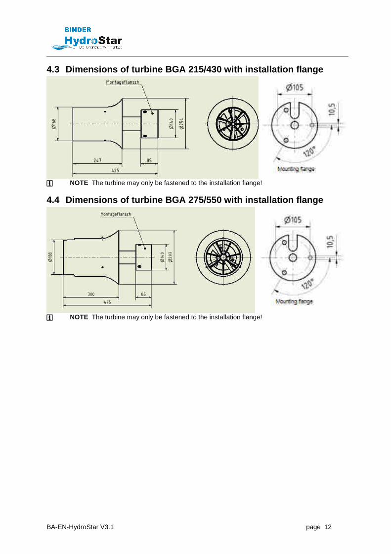
4.3 Dimensions of turbine BGA 215/430 with installation flange
NOTE The turbine may only be fastened to the installation flange!
4.4 Dimensions of turbine BGA 275/550 with installation flange
NOTE The turbine may only be fastened to the installation flange!

BA-EN-HydroStar V3.1 page 13
5 HydroStar BGA 160/320/275/550 C for retrofit inst allation
• These units are ready for installation and manufactured according to order instructions. • The frame must be securely attached to the pool edge. • No attachment at the pool floor is necessary. • The feet should be adjusted so that the unit stands securely and the frame is not perpendicular. • The motor cable must be installed so that cannot be damaged. • The installation shaft must be completely under water. • The unit's suction is on the bottom and front side. It must be ensured that the suction slits are never
clogged and water flow is guaranteed. NOTE
• Do not climb on the frame or the installation shaft . • Do not use the installation shaft as a "starting bl ock". • Do not push-off from the cover plate.

BA-EN-HydroStar V3.1 page 14
6 PIEZO Tri / PIEZO Tri Square, installation
PIEZO Tri, installation in pool wall, installation shaft Ø120
PIEZO Tri, installation shaft Ø120, cover plate Ø130

BA-EN-HydroStar V3.1 page 15
PIEZO Tri Square, installation shaft with cover plate
PIEZO Tri Square, installation shaft 150 x 70 mm

BA-EN-HydroStar V3.1 page 16
7 Control unit • Observe DIN VDE 0100-702 (Installation of low volta ge systems, Section 702: Swimming
pools and other pools) . • The control unit must be installed in area 2 as per DIN VDE 0100-702. The power lead-in must be
equipped with residual current protection (RCD) with a rated residual operating current of ≤ 30mA. • The system must have a 16 A inert fuse installed. • Installation in a dry room in which other technical equipment for operating the swimming pool is
installed. The room should be a maximum of 10 m from the pool. • The control unit is designed for wall mounting. It is mounted with 4 screws Ø 8 mm (not included in
delivery). It must be fixed in such a way that the cable entries are on the bottom.
Mounting BGA 160/215/275
Mounting BGA 320/430/550
HydroStar BGA 160/215/275
HydroStar BGA 320/430/550
NOTE Please also observe the circuit diagrams included i n delivery!

BA-EN-HydroStar V3.1 page 17
7.1 Connection block diagram
The HydroStar BGA 320/430/550 Twin twice the motor terminals.
7.2 Terminals
• Connection is carried out by means of
screwless WAGO terminals • Please observe the information.
WARNINGThe wires for motor feed have a paper casing! Ensure that the paper casing is completely removed!

BA-EN-HydroStar V3.1 page 18
7.3 Motor connection • Insert the motor cable into the M25 threaded cable connection so that the jacket is pushed
through by approximately 50 mm. • Securely tighten the threaded cable connection. • Connect the motor supply line to the terminal strip according to the colour coding.
7.4 Extending the motor supply line NOTE: Observe the minimum cross-section of 16 mm²!
If it is necessary to lengthen the line, observe the motor's rotation direction. If the turbine is running in the wrong direction, invert the two connection lines.
• Shorten the original motor supply (3 x 6mm²) line t o ≤ 5 m (minimum 2 m) • Extend up to a total length of 30 m with a cable cr oss-section of 16 mm² fine wired! • To extend the turbine cable, the original BINDER 3x 16 mm² cable is recommended! (Art.
No.: 5300115)
7.5 Connecting the HydroStar PIEZO Tri • The connection cable is a 14-wire cable with cross-section of 0.5 mm2. • The cable can be lengthened with an equivalent cable up to 30 m. • It must be ensured that the wires are connected with the same numbering. • An underground junction box for cable lengthening must have a watertight seal. • Terminal strip X2 is used for connection. • Connect the wire number according to terminal number. • Please also observe the circuit diagrams included i n delivery!
NOTE: Please also observe the circuit diagrams incl uded in delivery!

BA-EN-HydroStar V3.1 page 19
7.6 Connecting an external operating device
By means of push buttons connected to the X2 terminal strip, the following functions can be controlled: • On/Off by closing terminals 1-2 • Turbine acceleration by closing terminals 1-8 • Turbine deceleration by closing terminals 1-11 • Breaking capacity: 24VDC/20mA, maximum cable length 30m • Please also observe the circuit diagrams included i n delivery!
7.6.1 Instructions for operation with a smartphone The X2 terminal strip can be used as an interface to an overriding control unit (e.g., Loxone). The terminal assignment can be found in the circuit diagrams included in delivery.
8 Start-up Turn the unit on using the rotary switch on the fro nt side of the control unit! ELECTRICAL HAZARD Before starting the machine up, check the operation of the residual current device (RCD) on the machine side. Check all lines for damage and make sure the electrical connections are secure. NOTE Do not perform any trial runs unless the turbine is completely under water! Operating it above water or only partly in water will cause the drive motor to fail!
8.1 Remote control operation DANGER The radio transmitter and receiver are pre-set to match at the factory and programmed for the operation of the HydroStar counterflow unit. Any reprogramming or using a second or third-party radio transmitter may damage the machine or harm people. Before starting the turbine, make sure that no one is in the flow out area of the turbine. The sudden flow of water may lead to unpredictable reactions.

BA-EN-HydroStar V3.1 page 20
P1 ON/OFF LED (optional)
P2 Colour change LED (optional)
P3 LED brighter (optional)
P4 LED darker (optional)
� Faster
� Slower
Turbine ON / OFF
☼ Keyboard light (10 sec.)
NOTE When the turbine is switched on, it always runs at the lowest speed!
Hand-held transmitter IP67
8.1.1 Switching the turbine on and off
• Turn the unit on by briefly pressing button . After a delay of approximately 7 seconds, the turbine starts running at the minimum motor speed.
• Turn the unit off by briefly pressing button . The speed of the turbines is reduced and after approximately 5-6 seconds, the unit is switched off.
The green/red LED above button P1/P2 indicates the actuation of a button on the remote control unit! NOTE After pressing the buttons of the hand transmitter, it takes approx. 2 seconds until the signal reaches the radio receiver. A hectic or repeated pressing of several keys can lead to malfunctions. NOTE The range of the radio transmitter is 50 m under ideal conditions. The range may be severely limited because of local conditions. If the range is insufficient, an external antenna with up to 20 meters of cable can be connected and installed in a more favorable position of the building. NOTE The radio transmitter fulfills protection class IP66 and IP67. A permanent submersion of the transmitter under water is not possible.
8.1.2 Water jet control By pressing the buttons � or �, the flow rate can be changed between the minimum and maximum speed.

BA-EN-HydroStar V3.1 page 21
9 Optional operation by PIEZO Tri
PIEZO Tri
If the HydroStar turbines are equipped with the PIEZO Tri switch, the HydroStar turbines can be operated both with radio remote control and with PIEZO Tri.
If the system is ready for operation, the LED ring of the -button lights up red. Press to confirm the on / off button, the system is switched on and the ring lighting changes the color. The water volume can be adjusted by pressing the buttons � or �. Indicate � and � by brief flashing in red, in which stage the turbine swimming system works. The button � is permanently red if the HydroStar is at the lowest level, the button � will remain red if the HydroStar is at the highest level, by pressing the ON / OFF button again the system turns off and the LED ring changes to red again. NOTE The unit can be switched on with the remote control, and switched back off by using the PIEZO Tri switch. Actuating by remote control is also indicated on the PIEZO Tri.

BA-EN-HydroStar V3.1 page 22
10 Optional operation via touch display
HydroStar Touch-Display
Several users can be created in the main menu. The swimming data and the training program are always stored under the registered user.
- Manual mode • Adjustment of the HydroStar output via slider • Representation of the power in percent, km/h, m/s und m³/h - Training program • You can set and run a sequence with duration (time) and intensity (power of the
system) • This sequence can be changed again and again - Wave motion • Simulates a recurring current which can be adjusted in duration and intensity - LED settings • Two LED sliders can be used to adjust the LED spotlight (optional) in the brightness
and the color. Slider = touch surface on the screen NOTE Our touch screens comply with protection class IP54, but should not be exposed to the weather.

BA-EN-HydroStar V3.1 page 23
11 End of operation At the end of operation and overnight, the machine should be switched off using the power switch on the control unit.
12 Shutdown / hibernation DANGER OF DAMAGE The turbine must not be allowed to freeze under any circumstances. Please observe the following instructions:
Two cases are considered during the wintering of the HydroStar turbines. In the first case, the water is discharged from the pool, the turbine is entirely over water and in the second case, the water is not drained from the pool and the turbine is completely under water. Case 1: • Turn off the control unit • Attach a sign. • Drain the water from the pool far enough that the turbine is completely above water. • Protect the turbine against frost getting in with suitable material.
After the frost period: • Remove insulating material from the turbine completely. • Make sure that there is no residual material in the propeller or in the flow straightener. • Refill the pool completely with water. • Start again as described in section 8. Start-up . Case 2: • Turbine remains installed • Turbine must be completely under water • A freezing of the water must be prevented to the turbine (300 mm below water level) • The turbine can be used during the winter against the freezing of the water • Turbine runs at low speed over a period of time • Pool is cleaned after wintering • Ensure that there are no extreme dirt or foreign parts on the impeller or in the flow straightener • Start as described in section 8 Commissioning
13 Maintenance and repair
13.1 General All work on the HydroStar counterflow unit must be carried out by trained personnel. Before working on the control unit, disconnect it from the mains and secure it against being accidently switched back on.
13.1.1 Maintenance • The HydroStar counterflow unit is maintenance-free. • The underwater motor has no seals that have to be maintained or replaced. • Make sure that no objects of pieces or clothing are caught on any protective equipment in the
intake area. Remove those items when the turbine is switched off. • Have a specialist inspect the counter current unit every two years. • The control unit can be cleaned with a damp cloth. Do not spray!
13.1.2 Repair • Repairs are only to be performed by suitably trained specialists or in the manufacturer's
factory. • Only use original BINDER spare parts for repairs.
BA-EN-HydroStar V3.1 page 24
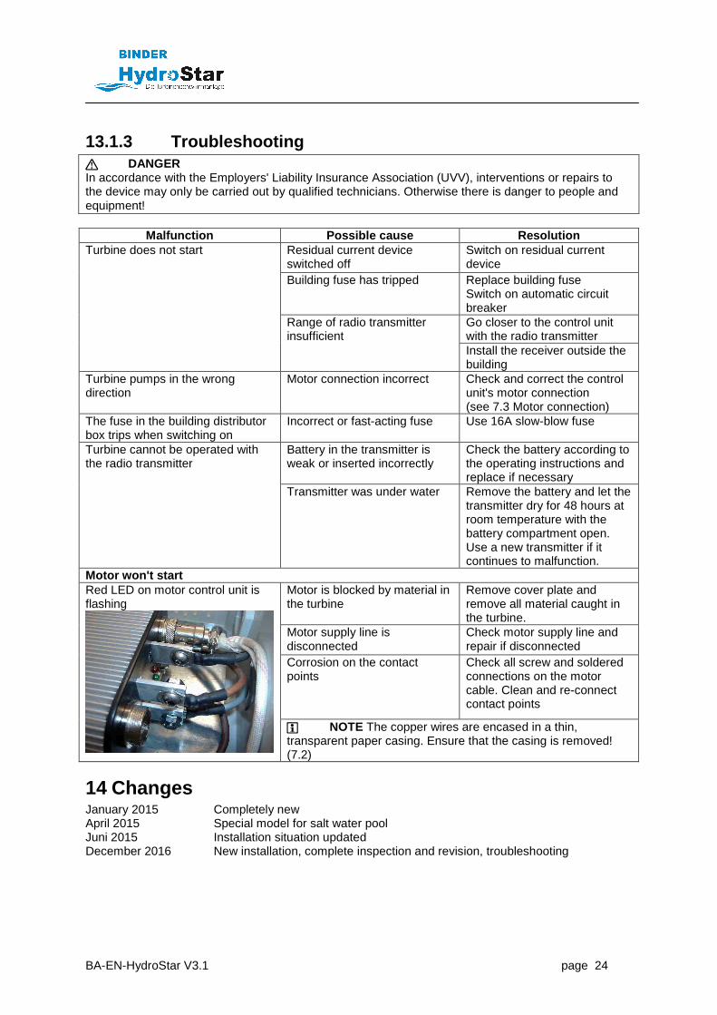
13.1.3 Troubleshooting DANGER In accordance with the Employers' Liability Insurance Association (UVV), interventions or repairs to the device may only be carried out by qualified technicians. Otherwise there is danger to people and equipment!
Malfunction Possible cause Resolution Residual current device switched off
Switch on residual current device
Building fuse has tripped Replace building fuse Switch on automatic circuit breaker Go closer to the control unit with the radio transmitter
Turbine does not start
Range of radio transmitter insufficient
Install the receiver outside the building
Turbine pumps in the wrong direction
Motor connection incorrect Check and correct the control unit's motor connection (see 7.3 Motor connection)
The fuse in the building distributor box trips when switching on
Incorrect or fast-acting fuse Use 16A slow-blow fuse
Battery in the transmitter is weak or inserted incorrectly
Check the battery according to the operating instructions and replace if necessary
Turbine cannot be operated with the radio transmitter
Transmitter was under water Remove the battery and let the transmitter dry for 48 hours at room temperature with the battery compartment open. Use a new transmitter if it continues to malfunction.
Motor won't start Motor is blocked by material in the turbine
Remove cover plate and remove all material caught in the turbine.
Motor supply line is disconnected
Check motor supply line and repair if disconnected
Corrosion on the contact points
Check all screw and soldered connections on the motor cable. Clean and re-connect contact points
Red LED on motor control unit is flashing
NOTE The copper wires are encased in a thin, transparent paper casing. Ensure that the casing is removed! (7.2)
14 Changes January 2015 Completely new April 2015 Special model for salt water pool Juni 2015 Installation situation updated December 2016 New installation, complete inspection and revision, troubleshooting

BA-EN-HydroStar V3.1 page 25
Recommended water properties:
� pH value: 6.8 – 7.8 � chloramine: ≤ 0.5 mg/litre (preferably around 0.0 mg/litre) � free chlorine: 0.3 – 2.0 mg/l ( 3000 – 20000 ppm) � cyanuric acid: ≤ 100 mg/litre � salt concentration: ≤ 0.4% ( 4000 ppm) ( 4 g/litre) � Metals: ≈ 0 mg/litre � carbonate hardness: ≥ 2°dH (°dH = mmol/litre x 2.8);(°eH =mmol/litre x 3.5);(°fH =
mmol/litre x 5.0) � ozone: 0 mg/litre � ∑chlorite + chlorate: ≤ 30 mg/litre � Redox potential: ≥ 700 mV
• Ideally, the pool water should be treated in accordance with DIN (19643 – 1) and/or German Federal Environmental Agency guidelines (hygienic requirements for swimming pools)!
• Please note that a sufficient quantity of fresh water must be fed into the pool in order
to prevent excessive salinity. This is best achieved by sufficient filter backwashing at regular intervals.
• Your swimming pool dealer will be glad to assist you with questions regarding water treatment and care.
• We use only premium quality materials that are optimally suited for swimming pool applications under the aforementioned conditions. However, in the event that one or more of the aforementioned parameters are not adhered to over an extended time period, or insufficient quantities of fresh water/no fresh water are/is fed into the pool, we will not accept liability for any damage incurred.