porous metal design guidebook - chand eisenmann metallurgical
TRANSCRIPT

Porous Metal Design Guidebook
Section 1: Introduction and Definition Section 2: Applications and Design Advantages Section 3: Manufacturing Methods Section 4: Materials and Properties Section 5: Designing and Specifying Porous Sintered Metals Section 6: Secondary Operations Section 7: Testing of Porous Sintered Materials Section 1: Introduction and Definitions This article provides general information about porous sintered metals made from metal powders, describes methods of manufacture and includes information concerning design data and applications. Porous metal materials have engineered, inter-connected porosity that are fabricated from metal powder particles using powder metallurgy (P/M) techniques. The following terms are helpful for understanding industry definitions and related standards: Pores- The open volume within the metal matrix or network. Interconnected Porosity- Pores that are connected together and to the surfaces of the component to allow fluid flow from one side to the other. By contrast, isolated pores do not have connectivity to both surfaces to allow fluid flow. Percent Porosity- a rough measure of the open volume equal to 100% minus the part density. The total open volumes of interconnected and isolated porosity are normally included in this value. Pore Shape, Pore Size and Pore Size Distribution are critical factors when describing the open volume available. Particle Retention Rating- indication of the size of the particles removed from a fluid during filtration. The test method and filtration efficiency must be specified to compare particle retention ratings of filters.

Micron Grade or Micron Rating- a comparative test result to describe the size of a hard spherical particle that is retained by the interconnected porosity. The Micron Rating is normally calculated from the pressure required to cause air to bubble from the largest pore in the part when submerged in a test liquid. The value is frequently referred to as the “Bubble Point” and is highly dependent on pore shape. Permeability- rate of fluid flow per specified surface area of a porous material at a given pressure differential. Section 2: Applications and Design Advantages The primary applications for porous sintered metals are the following:
1.) Filters for Separating Solids from Liquids and Gases; i.e., filters for catalyst retention, fuel oil burners, polymer processing, instruments, pressure regulators, cryogenic fluids, medical drug delivery systems
2.) Fluid Flow Metering and Pressure Control;
i.e., flow restrictors, calibrated leaks, breather vents, pneumatic delays, timing devices, gauge snubbers,and pressure equalization
3.) Storage Reservoirs for Liquids; i.e., self-lubricating bearings*, wicks, cooling devices, heat exchange elements 4.) Flame and Spark Arrestors for Safe Handling of Flammable Gases;
i.e., welding/cutting torch flame arrestors, electrical enclosures 5.) Sound Dampening and Attenuation: i.e., pneumatic mufflers and silencers, microphone attenuators 6.) Gas Distribution and Sparging;
i.e., fluidized bed surfaces, air bearings, vacuum plates, spargers for carbonation, oxygen stripping, ozone injection
7.) Media Retention; i.e., permeable barriers for desiccants, getters and purifiers

Important design advantages of porous P/M parts include:
1.) Performance; a. High strength, corrosion resistance and durability properties that are
characteristic of each base metal powder b. Controlled porosity to achieve specified filtration properties c. Controlled permeability to meet flow specifications d. Wide range of design possibilities permitting filtration of particles from 0.1 to 200
micrometers e. Flow rates from micro-leaks to high volumes f. Rigidity, shock resistance and ease of cleaning
2.) Availability;
a. Made from commercially available metal powders b. Supplied by experienced P/M manufacturers all over the world c. Manufactured in a variety of shapes and sizes
3.) Cost; a. Volume production techniques are well established b. Parts are usually well suited for automatic assembly
c. Close dimensional control is routinely achieved d. P/M's net-shape design feature eliminates the need for major machining and
minimizes scrap loss 4.) Wide Variety of Porous Metal Materials;
Major P/M porous materials include the following: a. Stainless Steel (Type 316L SS) b. Bronze (Copper-10%Tin) c. Nickel 200 d. Nickel Based Alloys (Monel ™, Inconel-™, Haynes-™) ™ registered trademark of Inco, Ltd. e. Titanium, Copper, Aluminum, and precious metals
5.) Industry Standards for Pore Size, Density and Permeability; a. Mean and Maximum Pore Size- ISO 4003 b. Bubble Point Pore Size- ASTM E128-61 c. Density- dry or wet measurement – ISO 2738 d. Permeability- ISO 4022

Section 3: Manufacturing Methods Depending on part size, configuration, and material as well as the degree of porosity required, most porous sintered metal products are fabricated by one of the following processes: 1. Axial Compaction and Sintering; Compacted Porous Component Powder Being Pressed Metal powder is pressed in a die at sufficient pressure that the powder particles adhere at their contact points with adequate strength for the formed part to be handled after ejection from the die. The “green” (unsintered) strength of the part depends on the metal powder characteristics (composition, particle size, shape, purity, etc.) and the forming pressure. Porous metal parts differ from standard P/M structural parts in that they are pressed at lower pressures and may tight mesh cuts of powder in order to achieve specified porosity requirements. After forming, the “green” parts are then heated, or sintered, under controlled atmosphere at a temperature below the melting point of the metal but still sufficient to bond the particles together, thus markedly increasing the part strength. Stainless Steel, Titanium, Nickel, Nickel Alloys and certain Bronze parts are most frequently processed by this method. Advantages include high production rates, good permeability control and excellent dimensional reproducibility. Part size and shape restrictions are those typical of P/M manufacturing process as described in the MPIF Design Solutions Brochure.

2. Gravity Sintering; Gravity or “loose powder” sintering is used to make porous metal parts from powders that diffusion-bond easily (most production parts are made from bronze). In this process, no outside pressure is applied to shape the part. The appropriate material, graded for size, is poured into a mold cavity, which is a void in the shape of the finished part. These metal particles are then heated to their sintering temperature at which point a metallurgical bonding takes place, and joining “necks” are formed at contact points. Metallurgical Bonding In consideration of the above process, the design engineer must, when considering gravity sintering of a part, visualize the final shape completely enclosed or surrounded by a mold, with the single exception of a “top” access hole through which the cavity can be filled with powder. The formed shape that can be easily extracted from that mold after it is sintered must also be visualized. Generally, a draft of 10 on the sides of the part is adequate for removal from the mold, although this “rule of thumb” does depend upon depth-of-fill and material grade.
Part tolerance should be as liberal as can be allowed for the following reason: although I.D.’s tend to be predictable, because the material usually shrinks to the core during sintering, the O.D. will vary somewhat from piece to piece depending on size, shape, material, density of “fill” etc. Hence, design tolerances of ± two percent should be used as a guide in gravity sintering. When required, closer tolerances can be held by a sizing operation. Overall part length should be specified to liberal dimensions, primarily to avoid secondary processing. Three percent would be a good general rule to follow. Specific values will vary with material grade or part shape.

3. Powder Rolling and Sintering; Porous P/M sheet is fabricated from stainless steel, copper, bronze, nickel based alloys and titanium. The sheet material is made by direct powder rolling or by gravity filling of molds and calendaring before sintering. Specified porosity is achieved by selecting the proper particle size of the powders. Depending on the density and material, the P/M sheet is available in a variety of thickness, from 0.25 mm (0.010") to 3 mm (0.12") and in area dimensions up to one square meter or several square feet. The sheet can be sheared, rolled and welded into different configurations. 4. Isostatic Compaction and Sintering;
Isostatic Compacting is a process by which pressure is applied uniformly to a deformable container holding the metal powder to be compacted. This technique is especially useful in the manufacturing of parts having a large length-to-diameter ratio. The system generally includes a pressure vessel designed to contain a fluid under high pressure, a deformable container and arbors (or cores) if tubes or special shapes are being made. By appropriate choice of pressurizing fluid and containers, the Isostatic process can be used at elevated temperatures (Hot Isostatic Pressing), although most porous parts are made at room temperature. The “green” part, removed from the Isostatic tooling, is sintered in the normal way. This process may be used with all conventional P/M materials.

5. Metal Spraying; Metal powders may be the source of a porous metal structure created by spraying molten metal onto a base with porosity control achieved by spraying conditions or by the co-spraying of a second material, which may later be removed. 6. Metal Coating and Sintering; Metal powders can be mixed with special binders to form slurry that can be applied to porous substrates or used to form net shape components. Special care and equipment is normally required to insure appropriate binder removal and uniform porosity. 7. Metal Injection Molding and Sintering; Porous materials can be fabricated by MIM processing by mixing metal powders with significant amounts of specially formulated binders to form a viscous material for high-pressure injection. Depending on the material characteristics and MIM tool design, unique components with controlled density can be formed. Due to the large amount of shrinkage that occurs during binder removal, special debinding and sintering equipment is required for processing materials by this method. Section 4: Materials and Properties
1.) Stainless Steel –
Type 316L (UNS 31603) Typical Composition: 18%Cr, 13% Ni, 2% Mo, 1% Si, 0.03% max C.

Porous parts are specified in stainless steel to take special advantage of that metal’s excellent resistance to heat and corrosion. From a manufacturing standpoint, any of the austenitic grades (Series 300) of stainless steels may be used; however, from a commercial point of view, only Type 316L is available in the wide range of particle sizes necessary to make porous P/M parts conforming to a variety of specifications. Moreover, Type 316L powder with its higher nickel and molybdenum content is more corrosion resistant than the standard Type 302/303 stainless. Stainless steel porous parts made from Type 316L have the same resistance to oxidation and degradation of strength at elevated temperatures as fully annealed Type 316L stainless. Corrosion resistance is somewhat less than wrought stainless because of the large amount of surface area and relatively small interparticle bonding.
2.) Bronze- Typical Composition: 89%Cu, 10% Sn, 1% Phosphorous The major advantage of porous P/M bronze over other porous sinter metals is lower cost. Since most porous bronze parts are made by gravity sintering of spherical or cylindrical powders, the processing costs are lower. However, mechanical properties of porous bronze parts are typically lower than for other porous metal materials that require compaction prior to sintering.

3.) Nickel and Nickel-Based Alloys
When special corrosion- or heat-resistant properties are required and stainless steel is not good enough, nickel-base alloys may be applicable. Filter grade powders are usually available in nickel, standard Monel ™ and Inconel ™ and some of the Hastelloys™. Before specifying these materials, the designer should consult his P/M vendor; a material substitution at the design stage may save a special purchase of powder with important cost savings.
a) Monel™ or Hastelloy™ may be used in acidic waters, where stainless steel will rust from crevice corrosion;
b) Inconel™ and the Hastelloys™ serve in high temperature and severe corrosion applications.
c) Nickel finds special applications not only in battery and fuel cell plates, but also in submicron particle filtration for high purity gas filtration applications.

Typical porosity and permeability data of porous Bronze and 316LSS are listed below:
4.) Titanium Porous Titanium offers excellent corrosion resistance and is ideally suited for filtration applications in harsh environments. Titanium porous materials are available in sheets, tubes and components with controlled porosity ranging from 100 Micron Grade down to 0.5 Micron Grade. Porous Titanium is more costly than other porous materials due to the special vacuum or argon sintering process requirements. Titanium materials are embrittled by trace amounts of oxygen or hydrogen during sintering, so special furnaces are required to avoid exposure to air or moisture. Commercially pure (99.5% minimum), Grade 2 titanium or higher purity is normally specified for medical, chemical or aerospace applications.

Section 5: Designing and Specifying Porous Sintered Metals
1.) Performance Characteristics
In designing for P/M porous metal parts, it is assumed the designer has a clear understanding of the function he wished the product to accomplish: in most cases, some phase of fluid control. For purpose of simplication, the performance functions are listed in four groups: ●
• Filtration – defined as a separation process (removal of a gas, liquid, or solid from a gas or liquid) with as low a pressure drop a feasible. ●
• Flow Control – defined as the establishment of a specific pressure drop in
a fluid flow system.
• Distribution – defined as the ability to provide a uniform fluid flow over a wide area, as in a sparger, air bearing or vacuum hold-down plate.
• Porosity – defined as the interconnected open area within the metal
matrix.
a) Filtration Porous sintered products are a depth-filtration medium with distribution of pore size and length of passage qualities that are a factor of particle size, shape, and part dimension. The depth-filter not only has more dirt-holding capacity that a screen filter, but also has a higher pressure drop than a screen of equivalent porosity rating.

Porous P/M parts are capable of extremely fine degrees of filtration. The subject of absolute vs. nominal filtration or micron ratings is too complex to be treated here; it is so complex, in fact, that much of the filter design in P/M porous media on new applications has been performance oriented (actual test of samples) rather than based on theoretical design data. In designing for filtration, a close relationship between part designer and P/M vendor is particularly important, because pressure drop is a function not only of the P/M structure, but of the working area and thickness as well. Often an increase in filtration area may be accomplished by proper selection of part shape and dimensions, but this choice must be made with full knowledge of its effect on P/M part manufacture. Porous P/M filter parts are sturdy and rigid, not as susceptible to mechanical damage as fine screens, not as fragile as ceramic filters, nor as deformable as organic felted materials. The designer with a filtration problem should look at all functional aspects with a value analysis technique. In most instances, there will be a potential trade-off between precision of separation and permissible pressure drops (see chart). The variety of available shapes and the easy assembly of P/M parts can offer many manufacturing economies.
b) Flow Control By close control of the product manufacturing process, the P/M parts maker can vary the porosity of the part from less than 10% to more than 60%. By porosity control, the P/M parts maker can vary the pressure drop in the fluid flow with considerable precision. The process is particularly well adapted to the volume production of precision “leaks” used in such applications as timers, gas supply control elements and other applications which might otherwise be controlled by precision orifices or fixed valves. P/M flow

control parts today are made in very large quantities for pneumatic timers, time delay elements in automotive applications, and precision instrument gas supplies. Because controlled porosity P/M parts are suitable for such a wide range of uses, it is important to repeat these important recommendations: ● the specifications should reflect functional requirements; ● acceptance tests should be determined on a cooperative basis between customer and vendor. P/M dimensional reproducibility and permeability mean that the “in-place” cost of P/M parts can be less than cotton or cloth. In acoustical application, for example, P/M allows automatic assembly and often eliminates secondary custom “doping” of individual products. Low pressure air flow properties or actual acoustical resistance values are usually specified. Water repellent breathers of treated porous metal permit military electronic devices to breathe during operation but prevent water damage if the item is submerged. Similar parts are used to provide pressure equalization for equipment undergoing altitude changes in aircraft. Specifications normally state minimum water retention and minimum air flow values. P/M flow restrictors compete successfully with orifices and capillary tubing on the basis of both economy and quality. The flow vs. pressure drop relation is much closer to linear than either orifices, or capillaries and can be adjusted by controlling density, particle size and part geometry. A single piece of contaminant, which can block an orifice or capillary, will leave the P/M part unaffected. Quantities of smaller contaminants, of course, will gradually increase restriction. But this can be solved in automotive devices, for example, by inserting a larger diameter P/M part with a smaller pore size upstream of the restrictor to pre-filter the fluid and prolong the life of the restrictor. P/M flow restrictors are analogous to electrical resistors and can perform as many functions in pneumatic, fluidic or vacuum circuits as their counterparts in electronic circuits. Specifications of these parts usually indicate a maximum and minimum time delay under precisely defined conditions or a high and low flow at a given pressure drop. Maximum and minimum pressure differentials at constant flow rates can also be used.

Pneumatic silencers and pressure snubbers are excellent examples of the ability of P/M parts to smooth out surges in pressurized liquid or gaseous systems. Minimum air flows at a particular pressure drop determine properties of these parts.
Permeability Permeability is a measure of the pressure drop at a given flow of a specified fluid through a unit area of the filter. Parts made by gravity sintering have a porosity/permeability relationship primarily controlled by the powder size.

Compacted P/M porous parts may be made with a range of porosity/permeability ratios, depending upon the density achieved in the pressing operation. Variations in permeability of 3:1 or more can be achieved in parts of similar porosity. Advantage may be taken of this control to make flow control elements. If the part is not a filter, the designer should specify the desired permeability, leaving the porosity choice up to the manufacturer.
c) Distribution
The design of gas distribution devices utilizing P/M parts is primarily one of specification of function. The design of a sparger, used to introduce a gas under the surface of a liquid, is controlled by the amount of space available, liquid characteristics (temperature and corrosive properties), bubble size desired (usually small), quantity of gas to be introduced and pressure of the gas. These requirements usually are sufficient for the user and the manufacturer to arrive at the optimum choice of both material and part shape. A vacuum hold-down or its counterpart, an air bearing, is normally specified on the basis of past experience of the user or manufacturer. Porous metal P/M parts may be used as air distribution manifolds to supply large quantities of air over a specified area at a low velocity. Design specifications are again performance requirements: volume of gas over a specified area at a given pressure drops. P/M parts are generally used where their superior strength, corrosion and heat resistance properties are needed (as compared to organic porous materials), or where they are less expensive to produce than machined metal manifolds. In the design of porous metal parts, the importance of practical “cut-and-try” evaluation cannot be stressed enough. It is a more practical approach and usually less costly than a theoretical analysis, which must generally be based on inadequate data.
d) Porosity Porosity is a quality, which is difficult to define precisely, because the total interconnected porosity is not only a range of hole diameters but also of passages of varying lengths and tortuosity. To determine porosity the P/M industry uses the “bubble point” test, which measures the pressure at which a bubble forms at the part surface as submerged in alcohol. The micron rating is roughly related to particle removal ability. The lower the rating, the finer the powder used to make the part and the higher the pressure drop. For filter design, the customer should specify a porous metal part by the maximum size particles acceptable in the filtrant and the P/M manufacturer will work to attain the minimum pressure drop at that micron rating. Commercial testing equipment is available to determine pore size distribution with values of mean and maximum pore size measured for media comparison.

2) Mechanical Properties
a) Strength The strength and moduli of a porous P/M part are related to the density and the properties of the fully annealed base metal.
b) Shape
As previously mentioned, the optimum shape of a part is controlled not only by the space available, but also by the method of manufacture. Each manufacturing method has its own set of advantages and disadvantages.

Gravity sintered parts have certain restrictions-for example, some draft must be allowed on longer parts-there is a 1 percent taper minimum-and certain advantages- i.e. low tooling cost, ability to make cones and tapering sections and undercuts. Compacting is well suited to making parts with no drafts, high volume and excellent reproducibility of properties and dimensions; however, undercuts should be avoided and tapered or long parts cannot be made. Isostatic compacting can produce long tubes or rods, conical and complex shapes, but the unit cost may be high.
Some of the design limitations are listed below:
Gravity sintering Size – from very small parts up to dimensions where furnace size is only limitation; six foot diameter or more; porous sheets to 24” x 60”
Compacting/sintering Size – from under .020” in diameter to 12” diameter, limited by press and furnace size; length/diameter ratio preferably under 2.5:1 Tolerances - ± ½% in diameter and ±2% thickness

Isostatic compacting/sintering Size – from 1/8” diameter to size limited by equipment; 3” is common, 72” is possible; length to 72” usually achieved by Butt welding of shorter sections Tolerances - ± 5%in diameter CHAMFERS Chamfered edges can be added to P/M parts, in most cases at no additional cost to the piece price. This design feature permits easier assembly in press-fit operations and strengthens the edge of parts made by pressing which is particularly important in high porosity, coarse-grained parts. Both top and bottom edges may be chamfered for parts made by pressing; but in the case of gravity sintered parts, only one edge may be chamfered. Specifying Guidelines When specifying P/M porous media, the following information will be most helpful to the fabricator:
1. What is the application? (filtration, fluidization, gas dispersion in a liquid, silencing, oil or other liquid extraction from a gas, etc.)
2. What will pass through the part? 3. What are the corrosion problems? 4. What special operating conditions, such as temperature or pressure, are
involved? 5. What contaminants might be encountered? 6. What dimensions, shape and tolerance are required? 7. How many units are needed? 8. How is it to be mounted or supported? 9. What is the desirable rate of flow and the allowable pressure drop across the
filter unit; what is the system pressure? It will also be helpful to the manufacturer if the designer would not specify non-pertinent parameters. It is very important that a customer work closely with the vendor for other specifying information. (For the names and address of vendors, contact Metal Powder Industries Federation, 105 College Road East, Princeton, New Jersey 08540.)

Section 6: Secondary Operations
1. Press Fitting and Sinterbonding Machined parts can be attached to porous P/M parts of similar composition by sinterbonding a press fit assembly in the initial sintering operation or during a secondary heat treatment cycle. Press fitting works well because the porous materials can be easily deformed. A good metallurgical bond can be achieved by forming diffusion bonds between the point contacts of the porous material and the hardware components. Assemblies can be made by placing a machined part in the gravity sintering mold or specially designed compaction tooling and then adding the powder prior to sintering. Alternatively, sintered porous parts can be press fit into the hardware, typically with a 1-3% interference fit depending on part size and material, and then sintered again to form the metallurgical bond. 2. Machining Porous P/M parts have their greatest uniformity as-sintered. If at all possible, therefore, it is best to design the P/M tooling so that the porous part requires no finishing on the working surfaces after sintering. While there are some techniques for machining porous parts and still retaining their porosity, most machining operations tend to close the pores. If machining or grinding is required to achieve specified shape, dimensions, or surface finish, very sharp tooling with a slight negative rake should be used. Working area should also be subsequently treated to remove the cutting fluids and to etch open the smeared pores. Then, careful cleaning is required to flush out all the etchant. It is recommended that these operations be left to the vendor.

Electrical Discharge Machining (EDM) and laser cutting offer alternative methods to conventional machining to form special shapes. While conventional machining and laser cutting normally require acid etching to remove the smeared surface metal and to reactivate the pores, proper EDM processing can keep the pores open, so that only a thorough cleaning is required. EDM processing is normally reserved for prototype components due to higher processing and associated cleaning costs. Laser cutting and machining can offer inexpensive options for production volumes when the surface porosity does not require reactivation. Machining the non-working area of porous metal parts is preferably done without a coolant and the parts to be machined should be handled with clean hands on well cleaned equipment free from residual oil. It is better to add a machined component by sinter-bonding, welding or adhesive bonding. 3. Welding, Brazing and Soldering Porous stainless steel structures can be readily assembled by welding a porous part either to another porous part or to a machined part. Inert arc welding should be used. If the welder is not experienced in working with this material, he should be supplied some prototype parts to sample weld. The parts suppliers may be consulted for guidance as to the design of mating parts. In most cases the parts supplier can provide the final welded assembly.
Soldering, either hard or soft, and brazing are not recommended with porous P/M parts because the porous matrix material tends to “soak up” the flux and solder due to capillary action.

However, some special brazing materials and thermal cycles have been developed to "freeze" the flow of braze material in the joint area and to develop a good bond. Overall, TIG welding or lower heat input welding methods such as laser welding or Electron Beam Welding are the recommended joining methods to provide adequate mechanical properties and proper sealing. 4. Epoxy Bonding Epoxy bonding is another feasible joining method that can be applied in some limited applications. Higher viscosity epoxy works well since the epoxy cannot easily wick away from the joint area prior to hardening, unlike other lower viscosity glues. The development of higher temperature and more corrosion resistant epoxies has allowed longer service life in less severe application environments. 5. Cleaning
Many porous P/M parts are made so inexpensively that they can be discarded after use. More expensive parts and assemblies can be cleaned in solvents, by back flushing or by burning out the contaminants. Cleaning techniques will depend on the material being removed by and retained in the P/M part, and on the filter base material. 6. Storage and Handling
Proper care must be exercised when storing and handling porous P/M parts. The best practice is to keep parts in their original shipping container in a reasonably dry atmosphere. Specialized clean handling processes such as "Organic Free" processing, "Clean Room" type handling and “High Purity, Particle Free” bagging are recommended for critical applications in applications for the medical, semiconductor, telecommunications and analytical instrument industries. Porous parts can also be cleaned for safe handling in oxygen service applications. 7. Insert Molding Porous metal components are good candidates for insert molding with various thermoplastics and engineered resins. The plastic material can wick into the edge porosity to form a good seal and a mechanically sound bond between the porous component and the plastic injection molded component.
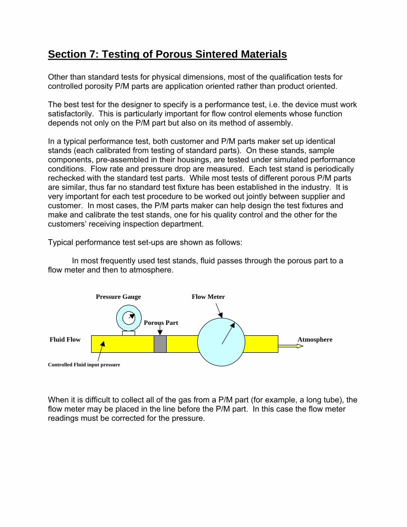
Section 7: Testing of Porous Sintered Materials Other than standard tests for physical dimensions, most of the qualification tests for controlled porosity P/M parts are application oriented rather than product oriented. The best test for the designer to specify is a performance test, i.e. the device must work satisfactorily. This is particularly important for flow control elements whose function depends not only on the P/M part but also on its method of assembly. In a typical performance test, both customer and P/M parts maker set up identical stands (each calibrated from testing of standard parts). On these stands, sample components, pre-assembled in their housings, are tested under simulated performance conditions. Flow rate and pressure drop are measured. Each test stand is periodically rechecked with the standard test parts. While most tests of different porous P/M parts are similar, thus far no standard test fixture has been established in the industry. It is very important for each test procedure to be worked out jointly between supplier and customer. In most cases, the P/M parts maker can help design the test fixtures and make and calibrate the test stands, one for his quality control and the other for the customers’ receiving inspection department. Typical performance test set-ups are shown as follows: In most frequently used test stands, fluid passes through the porous part to a flow meter and then to atmosphere. Pressure Gauge Flow Meter Porous Part Fluid Flow Atmosphere Controlled Fluid input pressure When it is difficult to collect all of the gas from a P/M part (for example, a long tube), the flow meter may be placed in the line before the P/M part. In this case the flow meter readings must be corrected for the pressure.

Pressure Gauge Flow Meter Porous Part Fluid Flow Atmosphere Controlled Fluid input pressure Parts used in time delay applications may be tested for elapsed time under simulated working conditions rather than in steady state flow. Pressure Gauge time for pressure to change from A to B A B Porous Part Atmosphere Constant volume container Several International Standards have been developed for testing permeable sintered metal materials: ISO 2738-Determination of Density, Oil Content and Open Porosity ISO 4022-Determination of Fluid Permeability ISO 4003- Determination of Bubble Test Pore Size (maximum pore size) ASTM E128-Standard Test method for Maximum Pore Diameter and Permeability of Rigid Porous Filters for Laboratory Use

Mechanical property testing, such as for tensile, burst, collapse and shear strengths, as well as ductility, can be measured to verify if the appropriate sintering conditions were applied during processing. Contact MPIF Porous Sintered Metals are highly engineered products that require the end user to work closely with the manufacturer to develop the component characteristics for each application. For the names and addresses of porous sintered metal suppliers, please contact the Metal Powder Industries Federation, at 105 College Road East, Princeton, NJ 08540 USA or at www.mpif.org.