position control for hysteresis motors: transient-time model and field-oriented...
TRANSCRIPT

IEEE TRANSACTIONS ON INDUSTRY APPLICATIONS, VOL. 54, NO. 4, JULY/AUGUST 2018 3197
Position Control for Hysteresis Motors:Transient-Time Model and Field-Oriented Control
Lei Zhou , Student Member, IEEE, Wolfgang Gruber , Member, IEEE, and David L. Trumper , Member, IEEE
Abstract—This paper studies the modeling and field-orientedcontrol (FOC) for hysteresis motors, with the goal of achieving po-sition control of hysteresis motors for servo applications. Hysteresismotors include a wide range of machines with solid cylindrical orring-shaped steel rotors, which generate torque primarily via themagnetic hysteresis effect of the rotor material. Previously, hys-teresis motors have been mainly used under open-loop operation.However, they are also attractive for position control in some spe-cial applications such as in-vacuum operation or when smooth run-ning and high speed is required. In this paper, an equivalent circuitmodel for hysteresis motors that describes the motor’s transient-time dynamics is introduced, and a state-space model for hystere-sis motors is developed. This model is used to construct a rotorflux orientation observer for the FOC for hysteresis motors. Threemethods for estimating the rotor field angle are introduced. Theproposed FOC-based position control method was tested with threehysteresis motors, including two custom-made motors of differentrotor materials and one off-the-shelf hysteresis motor. Experimen-tal results show that position control for all three hysteresis motorscan reach a bandwidth of 130 Hz with the proposed methods. Tothe authors’ best knowledge, this is the first experimental study onFOC and position control for hysteresis motors.
Index Terms—Field-oriented control (FOC), hysteresis motor,motion control.
NOMENCLATURE
is Stator current.us Stator voltage.iHr Hysteresis part of rotor apparent current.iEr Eddy current part of rotor apparent current.im is + iHr + iEr , magnetizing current.Φr Rotor flux.ΦHr Hysteresis part of rotor flux.ΦEr Eddy current part of rotor flux.μ Magnetic permeability.
Manuscript received July 28, 2017; revised December 15, 2017; acceptedFebruary 9, 2018. Date of publication March 5, 2018; date of current ver-sion July 17, 2018. Paper 2017-EMC-0668.R1, presented at the 2017 IEEEInternational Electric Machines and Drives Conference, Miami, FL, USA, May21–24, and approved for publication in the IEEE TRANSACTIONS ON INDUSTRY
APPLICATIONS by the Electric Machines Committee of the IEEE Industry Ap-plications Society. This work was supported by the Department of Science andTechnology, Government of India, under Grant DST/RCUK/JVCCE/2015/02(C). (Corresponding author: Lei Zhou.)
L. Zhou and D. L. Trumper are with the Department of Mechanical Engi-neering, Massachusetts Institute of Technology, Cambridge, MA 02139 USA(e-mail: [email protected]; [email protected]).
W. Gruber is with the Institute of Electrical Drives and Power Electronics, Jo-hannes Kepler University, Linz 4040, Austria (e-mail: [email protected]).
Color versions of one or more of the figures in this paper are available onlineat http://ieeexplore.ieee.org.
Digital Object Identifier 10.1109/TIA.2018.2812143
δ Hysteresis lag angle.ωe, ωr Motor electrical and mechanical speed.Rs , Lls Stator resistance and leakage inductance.Lm Mutual inductance.RH r , LlH r Hysteresis part rotor resistance and inductance.REr , LlEr Eddy current part rotor resistance and inductance.[ ] Denote estimated values.[ ]d , [ ]q Denote values in the rotor flux-oriented frame.[ ]D , [ ]Q Denote values in the stationary frame.[ ]rd , [ ]rq Denote values in the rotor-fixed frame.
I , J , 0[
1 00 1
],
[0 −11 0
],
[0 00 0
].
I. INTRODUCTION
AMONG many motor drive principles, the hysteresis motoris receiving increasing attention in the past decade due
to its advantages of simple structure, vibration-free operation,high rotor thermal and mechanical robustness, and self-startingcapability. A hysteresis motor operates using the magnetic hys-teresis of its rotor material. Since the magnetization in the rotorlags behind the external magnetizing force, a torque is generateddue to the stator and rotor field interactions [1].
There are a wide range of rotor materials for hysteresis mo-tors, including tool steel, chrome and/or cobalt alloy, and Al-NiCo magnets. As a result, the hysteresis motor encompasses awide range of constructions. Fig. 1 shows an illustration of themotor type categorization according to the magnetic hardnessof the rotor magnetic material. In this paper, we study hystere-sis motors of different rotor magnetic hardness using a unifiedframework.
The common operation state for hysteresis motors is runningasynchronously in transients and synchronously in steady state.Typical applications for hysteresis motors include tape drives[2], pumps [3], [4], centrifuges [5], flywheels [6], [7], etc. Forthese operation modes, speed feedback control is typically notrequired, as the dynamics of a hysteresis motor are stable and ro-bust under open-loop control. However, the open-loop dynamicsof a hysteresis motor are usually relatively slow-converging andlightly damped, which makes the motor unsuitable for applica-tions where dynamic performance is critical. This fact motivatesour research for methods to control the motor’s torque with highbandwidth, which is desired for some applications of hysteresismotors such as gyroscopes [8] and reaction wheels [9]. Thisadvancement can also allow hysteresis motors to be used forservo applications, which may be attractive for some special
0093-9994 © 2018 IEEE. Personal use is permitted, but republication/redistribution requires IEEE permission.See http://www.ieee.org/publications standards/publications/rights/index.html for more information.

3198 IEEE TRANSACTIONS ON INDUSTRY APPLICATIONS, VOL. 54, NO. 4, JULY/AUGUST 2018
Fig. 1. Ranges of motor concepts according to the magnetic hardness of the rotor material.
applications, such as high temperature or in-vacuum operations,and when smooth running and high speed is required. Prior work[10] studies the sensorless field-oriented control (FOC) for hys-teresis motors and presents simulations of the proposed scheme.However, to our knowledge, experimental studies for FOC andposition control for hysteresis motors have not yet been reportedin the literature.
This paper is based on [11] and studies modeling and FOC forhysteresis motors, targeting at enabling high bandwidth torquecontrol for hysteresis motors, and thus enabling them being usedfor position servo applications. The main objectives of this paperare as follows.
1) Propose a novel equivalent circuit model that describesthe hysteresis motor’s transient-time dynamics, whichcan be used to design a real-time flux observer forhysteresis motors.
2) Introduce the FOC method for hysteresis motors, andpropose several approaches for rotor flux orientationestimation.
3) Experimentally test the position control method on threedifferent hysteresis motors. Experiments show that theposition control based on proposed methods are successfulfor all three hysteresis motors.
To our knowledge, this paper presents the first experimentalstudy for FOC and position control for hysteresis motors.
The rest of this paper is organized as follows. Section IIbriefly introduces the operation principles for hysteresis motors.Section III presents the modeling for hysteresis motors.Section IV focuses on the FOC for hysteresis motors. Section Vshows the experimental results. Conclusions and future workare outlined in Section VI.
II. OPERATION PRINCIPLE OF HYSTERESIS MOTOR
This section briefly introduces the operation principle of hys-teresis motors to make the paper self-contained. A hysteresismotor consists of a regular polyphase stator and a rotor of solidcylindrical or ring-shaped semihard magnetic material. Some-times, the semihard magnetic material is in a ring around analuminum core. The magnetic hysteresis effects of the rotor ma-terial causes a lag angle between the rotor magnetic field and theair-gap magnetic field, and a hysteresis torque can be generated[1]. When the rotor of the hysteresis motor is conductive, eddycurrent effects also contribute to the torque generation when themotor is operating asynchronously.
Fig. 2 shows the ideal and practical hysteresis motor torque–speed curve, where Tm is the motor torque, ωm is the motor
Fig. 2. Typical single-pole-pair hysteresis motor torque–speed curve. Solidblue line: ideal hysteresis motor torque–speed curve. Dashed red line: Practicalhysteresis motor torque–speed curve, where the effect of eddy currents is takeninto account.
speed, and ωe is the electrical driving frequency. The idealhysteresis motor demonstrates constant hysteresis torque dur-ing asynchronous operation, assuming the hysteresis lag an-gle equals its maximum when slip is nonzero. At synchronousspeed, the motor torque can demonstrate different values, de-pending on the load torque and the motor excitation conditions.As a result, the ideal torque–speed curve demonstrates a “torquesingularity” at ωm = ωe . In a practical hysteresis motor with aconductive rotor, eddy currents in rotor generate an additionalslip-frequency-dependent eddy current torque when in asyn-chronous operation, making the motor torque vary with the slipfrequency. At the vicinity of synchronous speed, the practicalhysteresis motor torque demonstrates smooth transition fromthe motoring mode to the generating mode. This is because thehysteresis lag angle at the vicinity of synchronous speed is lessthan its maximum value, as is discussed in [12].
III. MODELING OF THE HYSTERESIS MOTORS
A. Time-Average Model of Hysteresis Motor
This section presents the equivalent circuit model for hys-teresis motors. Modeling of the hysteresis motor is challengingmainly due to the nonlinearity of hysteresis material properties.Through the years, several different models have been developedto study the motor’s behavior [5], [13]–[15]. Hysteresis motorswith eddy current effect being considered have also been studied[12], [14], [16], [17].
In this paper, the elliptical hysteresis loop based model forhysteresis motors proposed in [15] and [16] is used to model themotor dynamics. This model has later been used in[18]–[20]. In

ZHOU et al.: POSITION CONTROL FOR HYSTERESIS MOTORS: TRANSIENT-TIME MODEL AND FIELD-ORIENTED CONTROL 3199
Fig. 3. Time-average per phase equivalent circuit model for hysteresis motorsintroduced in [16].
this model, the B–H curve of the rotor material is approximatedby an ellipse, as B = Bm cos θ, H = (Bm /μ) cos (θ + δ),where Bm is the maximum amplitude of the flux density, μis the permeability of the rotor material, and δ is the lag anglebetween field intensity H and flux density B. This model con-siders only the fundamental harmonics for B- and H-field. Bymaking μ and δ as functions of the excitation amplitude, themagnetic saturation effect can be modeled.
The elliptical hysteresis approximation allows modeling thehysteresis motor dynamics using linear circuit elements. Fig. 3shows the hysteresis motor equivalent circuit model based on theelliptical hysteresis approximation with the eddy current effectconsidered developed in [16]. In this model, is is the stator cur-rent, im is the magnetizing current, and ir is the apparent rotorcurrent. The values of the circuit elements can be calculated by
Lm =2mKw
2N 2μ0lrg
p2πg(1)
RH r = ωemKw
2N 2Vrμ
π2rr2
sin δ (2)
LlH r =mKw
2N 2Vrμ
π2rr2
cos δ (3)
REr =l
ρAh, LlEr ≈ 0. (4)
Here, Kw is the winding factor, m is the number of phases, pis the number of poles, rr is the mean radius of the length of themagnetic field path within rotor, rg is the mean radius of the airgap, ωe is the reference speed, N is the number of windings perphase per pole, g is the air-gap length, l is the rotor axial length,Vr is the effective rotor volume, ρ is the specific resistivity of therotor material, and Ah is the effective axial cross-sectional areaof the rotor. The stator core loss is ignored in this model. Notethat this model only captures the hysteresis torque of the motorwhen it is operating asynchronously, which is everywhere exceptfor the “torque singularity” in Fig. 2 at ωm = ωe . In order toproduce a model that describes the transition from asynchronousto synchronous operation of a hysteresis motor, one needs tomodel the minor hysteresis loops of rotor material, which iscomplicated due to the nonlinearity and history dependency ofhysteresis properties. The work in [21] studies the use of such amodel for hysteresis motors through the finite-element method.
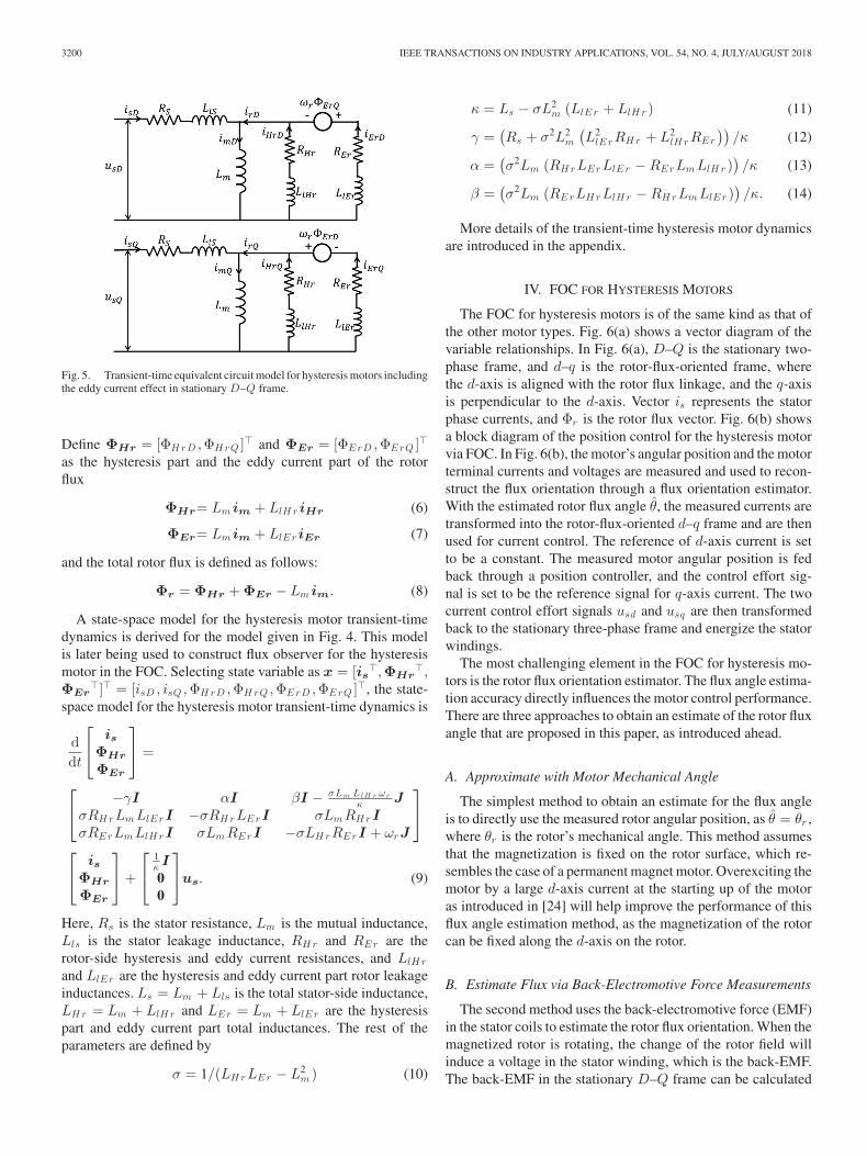
Fig. 4. Hysteresis motor circuit diagram with hysteresis effect and eddy cur-rent effect in different coordinate systems.
B. Transient-Time Dynamic Model of Hysteresis Motor
The hysteresis motor equivalent circuit model shown in Fig. 3is a time-average model, which describes the relationships be-tween the time-average relationships between the motor cur-rents, fluxes, and voltages. In order to design a real-time fluxestimator for the motor and thus to achieve a precise estimationof the rotor flux orientation, a dynamic model that describesthe instantaneous current-voltage-flux relationships in a motoris needed. This model is expected to be in a form that resemblesthe dynamic equivalent circuit model for induction motor FOC[22], [23].
The challenge of setting up a transient-time dynamic modelfor hysteresis motors is mainly due to the fact that the hysteresiseffect and the eddy current effect need to be modeled in differentreference frames. The hysteresis effect of the rotor would causea constant lag angle between the rotor flux and the air-gap flux,and this relationship should be modeled in the stator-fixed frame.On the other hand, the eddy current effect should be modeledin the rotor-fixed frame, since the eddy currents in the rotorare created in the conductors fixed on the rotor. This separationin reference frames is depicted in Fig. 4. This prevents us frommodeling the rotor flux using unified variables as in an inductionmotor model.
In this paper, a transient-time dynamic model for hystere-sis motors with eddy current effects considered is developed.Fig. 5 shows the transient-time equivalent circuit model forthe hysteresis motor in the stationary D–Q frame. In Fig. 5,is = [isD , isQ ]� is the stator current, iHr = [iH rD , iH rQ ]� isthe hysteresis part rotor current, and iEr = [iErD , iErQ ]� is theeddy current part rotor current. Define im = [imD , imQ ]� to bethe magnetizing current as follows:
im = is + iHr + iEr. (5)
Note that in the transient-time equivalent circuit model ofFig. 5, there are rotor-speed-dependent voltage sources on theeddy current part of the rotor-side circuits. This is becausethe reference frame change for the eddy current effect rela-tionships from the rotor-fixed frame to the stationary frame.
3200 IEEE TRANSACTIONS ON INDUSTRY APPLICATIONS, VOL. 54, NO. 4, JULY/AUGUST 2018
Fig. 5. Transient-time equivalent circuit model for hysteresis motors includingthe eddy current effect in stationary D–Q frame.
Define ΦHr = [ΦH rD ,ΦH rQ ]� and ΦEr = [ΦErD ,ΦErQ ]�
as the hysteresis part and the eddy current part of the rotorflux
ΦHr= Lm im + LlH r iHr (6)
ΦEr= Lm im + LlEr iEr (7)
and the total rotor flux is defined as follows:
Φr = ΦHr + ΦEr − Lm im. (8)
A state-space model for the hysteresis motor transient-timedynamics is derived for the model given in Fig. 4. This modelis later being used to construct flux observer for the hysteresismotor in the FOC. Selecting state variable as x = [is
�,ΦHr�,
ΦEr�]� = [isD , isQ ,ΦH rD ,ΦH rQ ,ΦErD ,ΦErQ ]�, the state-
space model for the hysteresis motor transient-time dynamics is
ddt
⎡⎣ is
ΦHr
ΦEr
⎤⎦ =
⎡⎣ −γI αI βI − σLm Ll H r ωr
κ JσRH rLm LlErI −σRH rLErI σLm RH rIσRErLm LlH rI σLm RErI −σLH rRErI + ωrJ
⎤⎦
⎡⎣ is
ΦHr
ΦEr
⎤⎦ +
⎡⎣
1κ I00
⎤⎦us. (9)
Here, Rs is the stator resistance, Lm is the mutual inductance,Lls is the stator leakage inductance, RH r and REr are therotor-side hysteresis and eddy current resistances, and LlH r
and LlEr are the hysteresis and eddy current part rotor leakageinductances. Ls = Lm + Lls is the total stator-side inductance,LH r = Lm + LlH r and LEr = Lm + LlEr are the hysteresispart and eddy current part total inductances. The rest of theparameters are defined by
σ = 1/(LH rLEr − L2m ) (10)
κ = Ls − σL2m (LlEr + LlH r ) (11)
γ =(Rs + σ2L2
m
(L2
lE rRH r + L2lH rREr
))/κ (12)
α =(σ2Lm (RH rLErLlEr − RErLm LlH r )
)/κ (13)
β =(σ2Lm (RErLH rLlH r − RH rLm LlEr )
)/κ. (14)
More details of the transient-time hysteresis motor dynamicsare introduced in the appendix.
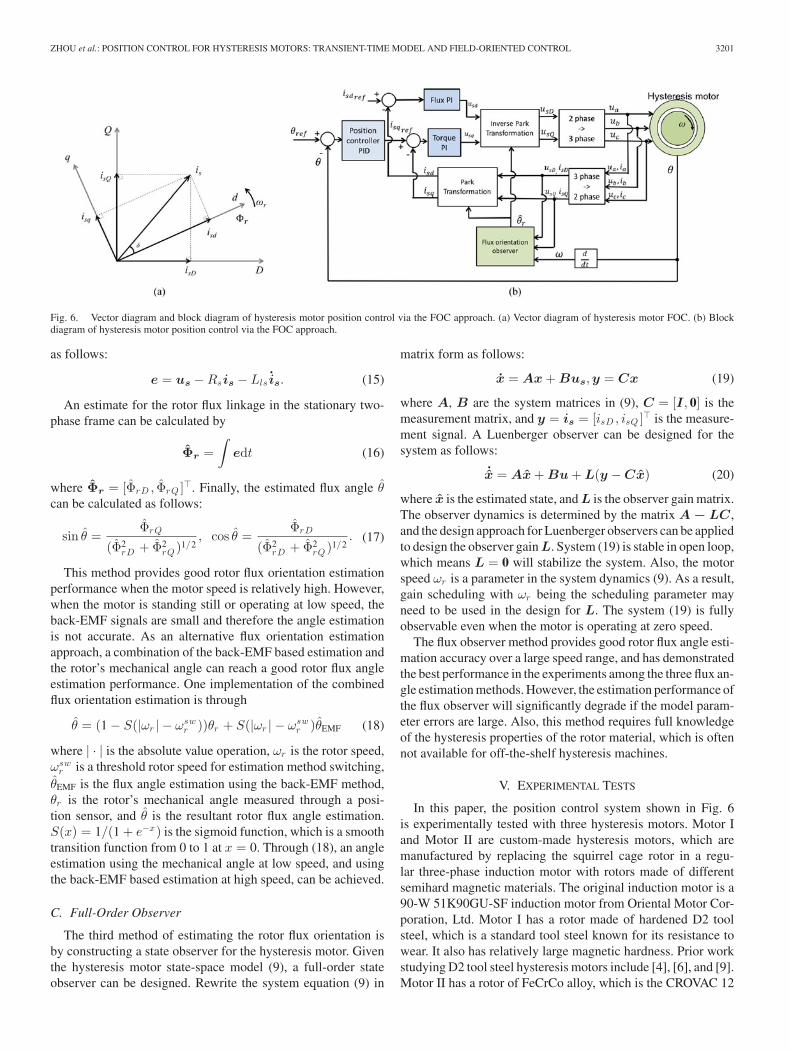
IV. FOC FOR HYSTERESIS MOTORS
The FOC for hysteresis motors is of the same kind as that ofthe other motor types. Fig. 6(a) shows a vector diagram of thevariable relationships. In Fig. 6(a), D–Q is the stationary two-phase frame, and d–q is the rotor-flux-oriented frame, wherethe d-axis is aligned with the rotor flux linkage, and the q-axisis perpendicular to the d-axis. Vector is represents the statorphase currents, and Φr is the rotor flux vector. Fig. 6(b) showsa block diagram of the position control for the hysteresis motorvia FOC. In Fig. 6(b), the motor’s angular position and the motorterminal currents and voltages are measured and used to recon-struct the flux orientation through a flux orientation estimator.With the estimated rotor flux angle θ, the measured currents aretransformed into the rotor-flux-oriented d–q frame and are thenused for current control. The reference of d-axis current is setto be a constant. The measured motor angular position is fedback through a position controller, and the control effort sig-nal is set to be the reference signal for q-axis current. The twocurrent control effort signals usd and usq are then transformedback to the stationary three-phase frame and energize the statorwindings.
The most challenging element in the FOC for hysteresis mo-tors is the rotor flux orientation estimator. The flux angle estima-tion accuracy directly influences the motor control performance.There are three approaches to obtain an estimate of the rotor fluxangle that are proposed in this paper, as introduced ahead.
A. Approximate with Motor Mechanical Angle
The simplest method to obtain an estimate for the flux angleis to directly use the measured rotor angular position, as θ = θr ,where θr is the rotor’s mechanical angle. This method assumesthat the magnetization is fixed on the rotor surface, which re-sembles the case of a permanent magnet motor. Overexciting themotor by a large d-axis current at the starting up of the motoras introduced in [24] will help improve the performance of thisflux angle estimation method, as the magnetization of the rotorcan be fixed along the d-axis on the rotor.
B. Estimate Flux via Back-Electromotive Force Measurements
The second method uses the back-electromotive force (EMF)in the stator coils to estimate the rotor flux orientation. When themagnetized rotor is rotating, the change of the rotor field willinduce a voltage in the stator winding, which is the back-EMF.The back-EMF in the stationary D–Q frame can be calculated
ZHOU et al.: POSITION CONTROL FOR HYSTERESIS MOTORS: TRANSIENT-TIME MODEL AND FIELD-ORIENTED CONTROL 3201
Fig. 6. Vector diagram and block diagram of hysteresis motor position control via the FOC approach. (a) Vector diagram of hysteresis motor FOC. (b) Blockdiagram of hysteresis motor position control via the FOC approach.
as follows:
e = us − Rsis − Lls is. (15)
An estimate for the rotor flux linkage in the stationary two-phase frame can be calculated by
Φr =∫
edt (16)
where Φr = [ΦrD , ΦrQ ]�. Finally, the estimated flux angle θcan be calculated as follows:
sin θ =ΦrQ
(Φ2rD + Φ2
rQ )1/2, cos θ =
ΦrD
(Φ2rD + Φ2
rQ )1/2. (17)
This method provides good rotor flux orientation estimationperformance when the motor speed is relatively high. However,when the motor is standing still or operating at low speed, theback-EMF signals are small and therefore the angle estimationis not accurate. As an alternative flux orientation estimationapproach, a combination of the back-EMF based estimation andthe rotor’s mechanical angle can reach a good rotor flux angleestimation performance. One implementation of the combinedflux orientation estimation is through
θ = (1 − S(|ωr | − ωswr ))θr + S(|ωr | − ωsw
r )θEMF (18)
where | · | is the absolute value operation, ωr is the rotor speed,ωsw
r is a threshold rotor speed for estimation method switching,θEMF is the flux angle estimation using the back-EMF method,θr is the rotor’s mechanical angle measured through a posi-tion sensor, and θ is the resultant rotor flux angle estimation.S(x) = 1/(1 + e−x) is the sigmoid function, which is a smoothtransition function from 0 to 1 at x = 0. Through (18), an angleestimation using the mechanical angle at low speed, and usingthe back-EMF based estimation at high speed, can be achieved.
C. Full-Order Observer
The third method of estimating the rotor flux orientation isby constructing a state observer for the hysteresis motor. Giventhe hysteresis motor state-space model (9), a full-order stateobserver can be designed. Rewrite the system equation (9) in
matrix form as follows:
x = Ax + Bus,y = Cx (19)
where A, B are the system matrices in (9), C = [I, 0] is themeasurement matrix, and y = is = [isD , isQ ]� is the measure-ment signal. A Luenberger observer can be designed for thesystem as follows:
˙x = Ax + Bu + L(y − Cx) (20)
where x is the estimated state, and L is the observer gain matrix.The observer dynamics is determined by the matrix A − LC,and the design approach for Luenberger observers can be appliedto design the observer gain L. System (19) is stable in open loop,which means L = 0 will stabilize the system. Also, the motorspeed ωr is a parameter in the system dynamics (9). As a result,gain scheduling with ωr being the scheduling parameter mayneed to be used in the design for L. The system (19) is fullyobservable even when the motor is operating at zero speed.
The flux observer method provides good rotor flux angle esti-mation accuracy over a large speed range, and has demonstratedthe best performance in the experiments among the three flux an-gle estimation methods. However, the estimation performance ofthe flux observer will significantly degrade if the model param-eter errors are large. Also, this method requires full knowledgeof the hysteresis properties of the rotor material, which is oftennot available for off-the-shelf hysteresis machines.
V. EXPERIMENTAL TESTS
In this paper, the position control system shown in Fig. 6is experimentally tested with three hysteresis motors. Motor Iand Motor II are custom-made hysteresis motors, which aremanufactured by replacing the squirrel cage rotor in a regu-lar three-phase induction motor with rotors made of differentsemihard magnetic materials. The original induction motor is a90-W 51K90GU-SF induction motor from Oriental Motor Cor-poration, Ltd. Motor I has a rotor made of hardened D2 toolsteel, which is a standard tool steel known for its resistance towear. It also has relatively large magnetic hardness. Prior workstudying D2 tool steel hysteresis motors include [4], [6], and [9].Motor II has a rotor of FeCrCo alloy, which is the CROVAC 12

3202 IEEE TRANSACTIONS ON INDUSTRY APPLICATIONS, VOL. 54, NO. 4, JULY/AUGUST 2018
Fig. 7. Photograph of a custom-made hysteresis motor with a 90-W inductionmotor stator connected to a BLDC load machine.
Fig. 8. Custom-made rotors for hysteresis motors. Left: D2 hysteresis rotorfor Motor I. Middle: FeCrCo alloy hysteresis rotor for Motor II. Right: Theoriginal squirrel cage rotor for the induction motor.
TABLE IPARAMETERS OF MOTOR I AND MOTOR II
Parameter Value
Motor power 90 WNumber of pole pairs 2Rated voltage 200–220 VRated RMS current 0.8 ARotor diameter 47.5 mmAir gap 0.4 mmNumber of turns per phase 8 × 80
material from Vacuumschmeltze GmbH. Motor I and Motor IIshare the same stator construction and rotor geometry, and theonly difference is in the rotor material. Fig. 7 shows a photo-graph of the induction motor stator with hysteresis rotor beingtested, and Fig. 8 shows the custom-made rotors for Motors Iand II and the original rotor for the induction motor. The pa-rameters of Motors I and II are shown in Table I. The thirdhysteresis motor being tested, Motor III is a commercial 250-W-type GLLHNNB-3529 hysteresis motor from Elinco, Inc.,Fig. 9 shows a photograph of the Motor III, and its parametersare shown in Table II.
In the experiments, the hysteresis motors are driven by apulse-width modulation (PWM) three-phase inverter manufac-
Fig. 9. Photograph of 250-W hysteresis synchronous motor from Elinco, Inc.
TABLE IIPARAMETERS OF MOTOR III
Parameter Value
Motor power 250 WNumber of pole pairs 2Rated voltage 163–236 VRated RMS current 2.6 A
tured by Linz Center of Mechatronics GmbH. The inverter oper-ates with a dc bus voltage of 200 V. The three-phase currents ofthe motors are measured through shunt resistors of the inverter,and are fed back for current control. A slotless, brushless dc(BLDC) motor BMS60 from Aerotech, Inc., is used as a loadmachine for the hysteresis motors, as is shown in Figs. 7 and9. The BLDC motor is driven by a current mode linear three-phase power amplifier using PA12 from Apex, Inc., where thecurrent controllers are implemented by analog circuits. The cur-rent control for the BLDC motor has a bandwidth of 2 kHz. Asine–cosine optical encoder on the load machine is being used tomeasure the rotor’s angular position, which can be interpolatedto a resolution of 105 pulse per revolution. The signal of thisencoder is also used for controlling the position of the hysteresismotor, and a stiff coupling is used to ensure stability. The con-trollers for the hysteresis motors are implemented in LabVIEWand are downloaded to a National Instruments PXI controllerwith field programmable gate array (FPGA) for execution. Thehysteresis motor current controller, PWM signal generation, en-coder interpolation, and the commutation for the BLDC motorare implemented in the FPGA with a process frequency of 40kHz, and the position controller and the flux orientation es-timator are implemented in the real-time control loop with asampling rate of 10 kHz. The hysteresis motor’s current controlhas a bandwidth of 600 Hz.
A. Hysteresis Measurement of Rotor Materials
This section presents the measurement and parameterizationof hysteresis properties of the rotor materials for Motor I andMotor II: the D2 tool steel and the FeCrCo alloy. Table III showsthe chemical, physical, and magnetic properties of the two rotormaterials.

ZHOU et al.: POSITION CONTROL FOR HYSTERESIS MOTORS: TRANSIENT-TIME MODEL AND FIELD-ORIENTED CONTROL 3203
TABLE IIIROTOR MATERIAL PROPERTIES
Material name D2 steel FeCrCo alloy
Material C: 1.5%; Co: 12%chemical Co: 1%; Cr: 28%composition Cr: 12 % Mo: 1%Conductivity 8.3 × 10⁶ S/m 1.4 × 10⁶ S/mRemanence 0.85–0.90 T 0.85–0.95 TCoercitivity 1.2–2.3 kA/m 16–32 kA/m
Fig. 10. Measured hysteresis properties of the D2 tool steel and the FeCrCoalloy under different sinusoidal B-field excitation amplitudes at 10 Hz. (a) D2tool steel. (b) FeCrCo alloy.
The B–H curves of the two rotor materials at different exci-tation amplitudes are measured and are shown in Fig. 10. Thework in [25] introduces the hysteresis measurement apparatus.It can be seen from Fig. 10 that the FeCrCo alloy has a largermagnetic coercivity than the D2 steel, while the saturation ofFeCrCo alloy is lower than that of the D2 steel. Since the hys-teresis torque generation of a hysteresis motor is proportional tothe hysteresis loop area [1], the FeCrCo alloy hysteresis motorcan potentially generate larger hysteresis torque than the D2steel hysteresis motor; however, it requires a larger H-field tofully utilize the hysteresis torque capability of the material.
There are two parameters in the elliptical hysteresis model:the permeability μ and the lag angle δ. Fig. 11 shows the hystere-sis parameters of D2 steel and the FeCrCo alloy under differentB-field amplitude. These parameters are stored in lookup ta-bles and are used to construct the model for hysteresis motors
Fig. 11. Measured μr and δ of the hysteresis motor rotor materials at 10 Hzunder different excitation amplitude. (a) D2 tool steel. (b) FeCrCo alloy.
through (1)–(4). With the two hysteresis parameters being func-tions of the excitation amplitude, the magnetic saturation effectcan be modeled.
B. Open-Loop Tests
The three hysteresis motors are first tested in open loop,i.e., the position control loop for the motors is not closed. Un-der this test condition, the stator windings are energized withsymmetric sinusoidal three-phase currents, and the motors aretested in no load condition.
Fig. 12 presents the speed startup curved of the three motors.In this test, the stator current zero-to-peak amplitude is 1 A forMotors I and II, and is 2.5 A for Motor III. It can be observed thatthe speed data of Motor II and Motor III demonstrates a largerspeed oscillation amplitude than that of the Motor I, whichis referred as a hunting behavior for hysteresis motors [26].Fig. 12 also shows that the Motor I has a shorter settling timethan Motors II and III. This is due to the D2 steel that has a largerconductivity than the FeCrCo alloy and the rotor material forMotor III, and thus the Motor I demonstrates a larger dampingthan the Motors II and III.
The motors’ starting torques are estimated though measuringthe slope of the speed during starting up. The drag torques to themotors, including air drag and the bearing friction, are identifiedthrough the deceleration of the motor after being disconnectedfrom the power sources, and are considered in the calculationof the motor starting torques. Fig. 13 shows the torque slip fre-quency relationship of the three hysteresis motors. Fig. 13(a)and (b) also presents the modeled torque calculated using the

3204 IEEE TRANSACTIONS ON INDUSTRY APPLICATIONS, VOL. 54, NO. 4, JULY/AUGUST 2018
Fig. 12. Startup speed of hysteresis motors at different reference frequencies. All speed data converge to synchronous. Peak current amplitude for Motors I andII: 1 A; peak current amplitude for Motor III: 2.5 A. (a) Motor I: D2 tool steel motor. (b) Motor II: FeCrCo alloy motor. (c) Motor III: Commercial hysteresismotor.
Fig. 13. Torque slip frequency curve of hysteresis motors. Solid line: Modeled torque. Marked lines: Measured torque. Peak current amplitude for Motor I andII: 1 A; peak current amplitude for Motor III: 2.5 A. (a) Motor I: D2 tool steel motor. (b) Motor II: FeCrCo alloy motor. (c) Motor III: Commercial hysteresismotor.
Fig. 14. Torque–current relationships of hysteresis motors at 20-Hz driving frequency. (a) Motor I: D2 tool steel motor. (b) Motor II: FeCrCo alloy motor.(c) Motor III: Commercial hysteresis motor.
Fig. 15. Measured plant Bode plots for three hysteresis motors. Input: q-axiscurrent amplitude; output: measured position.
Fig. 16. Measured closed-loop Bode plots for three hysteresis motors. Input:reference position; output: measured position. The −3 dB in magnitude plot isshown as the dashed line.

ZHOU et al.: POSITION CONTROL FOR HYSTERESIS MOTORS: TRANSIENT-TIME MODEL AND FIELD-ORIENTED CONTROL 3205
Fig. 17. Closed-loop position step response of three hysteresis motors under different load torque. The d-axis current for Motors I and II: 0.4 A. The d-axiscurrent for Motor III: 0.6 A. (a) Motor I: D2 tool steel motor. (b) Motor II: FeCrCo alloy motor. (c) Motor III: Commercial hysteresis motor.
Fig. 18. Position signal of hysteresis motors under step change of disturbance torque in the positive direction. The d-axis current for Motors I and II: 0.4 A. Thed-axis current for Motor III: 0.6 A. (a) Motor I: D2 tool steel motor. (b) Motor II: FeCrCo alloy motor. (c) Motor III: Commercial hysteresis motor.
time-average hysteresis motor equivalent circuit model shownin Fig. 3, with the motor geometric parameters and hysteresis pa-rameters of the specific rotor material being used. In Fig. 13(a)and (b), the modeled and measured torque data agree well athigh slip frequency, but have a relatively large difference atlow slip frequency. This is because the model assumes the hys-teresis lag angle is equal to its maximum whenever the motoris running asynchronously, i.e., the slip frequency is nonzero.However when the motor slip frequency is small, the lag anglecan demonstrate values smaller than the maximum lag angle,as discussed in [12]. Also, as is shown in Fig. 13(a) and (b),the torque of Motor I increases almost linearly with the slipfrequency, whereas the starting torque of Motor II saturates to acertain value when slip frequency is high. This indicates that thedominant torque generation mechanism of Motor I is throughthe eddy current effects, whereas the dominant torque genera-tion mechanism of Motor II is through the hysteresis effect.
Fig. 13(c) does not show the modeled torque for Motor IIIsince we lack the knowledge about the rotor hysteresis materialproperty for Motor III. Comparing Fig. 13(b) and (c), it canbe seen that the measured torque slip frequency relationship ofMotor III resembles that of Motor II, with both motor’s torquesaturate to a constant value as the slip frequency increases. Thisindicates that the torque generation of Motors II and III is mainlythrough the hysteresis effect.
Fig. 14 shows the measured torque–current relationships ofthe three hysteresis motors under blocked-rotor condition with adriving frequency of 20 Hz. It can be seen that the motor torqueis roughly quadratic with respect to the current.
C. Position Closed-Loop Control
The position closed-loop control scheme shown in Fig. 6 istested with the three hysteresis motors. The motors are firsttested under no load condition. For Motors I and Motor II, thefull-order state observer method given in (19) and (20) is usedfor the rotor flux orientation estimation. For Motor III, rotorflux orientation is estimated through the combination of themechanical angle and back-EMF method, which is shown in(18). This is because the full hysteresis motor model is availablefor Motors I and II, and is not available for Motor III dueto the lack of knowledge about the rotor material hysteresisproperties.
Fig. 15 shows the measured plant frequency responses of theposition control for the three hysteresis motors. In this mea-surement, the input signal is the q-axis current in the rotor-flux-oriented frame, and the output signal is the measured rotorangular position. It can be observed in Fig. 15 that all threemeasured Bode plots demonstrate −40 dB/dec slope at highfrequency, which follows the torque-to-position relationship ina motor. The Bode plots in Fig. 15 presents zero slope at lowfrequency due to the bearing friction, as is discussed in [27].This measurement indicates that the q-axis current is roughlyproportional to the torque of the motor. It also demonstrates thatthe proposed flux orientation estimation approach is successfulfor motors with known and unknown rotor hysteresis properties.
Fig. 16 shows the measured closed-loop Bode plots for the po-sition control systems for the hysteresis motors. Fig. 16 demon-strates that the bandwidth of the position control for the threehysteresis motors are above 130 Hz.

3206 IEEE TRANSACTIONS ON INDUSTRY APPLICATIONS, VOL. 54, NO. 4, JULY/AUGUST 2018
The hysteresis motors are also tested with load. Fig. 17 showsthe measured closed-loop position step responses of the threehysteresis motors under different constant load torques, andFig. 18 shows the hysteresis motor’s position signal under astep change of the load torque. In this experiment, the loadtorque is applied by the BLDC load motor, which is undercurrent control model. The magnitude of the load torque iscalculated through multiplying the load machine’s current andits torque constant. It can be seen through Fig. 17 that MotorI demonstrates larger position ripple than the Motors II and IIIwhen under a constant torque larger than 0.05 N·m. This isbecause Motor I uses ac current to compensate the large torque,and it demonstrates torque ripple under this condition due tothe high-order harmonics of the motor winding. In contrast,Motors II and III are able to compensate the load torque withdc currents in their windings. This experiment shows that thehysteresis motor’s position control are successful under differentload conditions, and also demonstrates that the position controlfor the three hysteresis motors are robust with respect to loadchanges.
VI. CONCLUSIONS AND FUTURE WORK
This paper studies the position control for hysteresis motorsby means of FOC. A transient-time hysteresis motor model isbeing developed, and three methods for estimating the rotor fluxorientation are proposed. Three hysteresis motors, including twocustom-made hysteresis motor with D2 steel rotor and Cobaltalloy rotor and one commercial hysteresis motor, are testedand have achieved successful position control. Suggested futurework includes the following.
1) Expand the hysteresis motor model to include the rotor’smagnetic remanence into the modeling to capture the his-tory state of the rotor magnetization.
2) Explore the thrust force and/or position control for linearhysteresis motors.
3) Study sensorless FOC for hysteresis motors.
APPENDIX
TRANSIENT-TIME HYSTERESIS MOTOR DYNAMICS
The transient-time dynamics of a hysteresis motor, whichare shown in Fig. 4, are briefly introduced in this section. Thismodel is being used to derive the hysteresis motor state-spacemodel (9). In an elementary model of the hysteresis motormodel, the stator flux Φs = [ΦsD ,ΦsQ ]�, hysteresis part ro-tor flux ΦHr = [ΦH rD ,ΦH rQ ]�, and eddy current part rotorflux ΦEr = [ΦErD ,ΦErQ ]� are defined as follows:
Φs = Llsis + Lm im (21)
ΦHr = Lm im + LlH r iHr (22)
ΦEr = Lm im + LlH r iEr. (23)
The stator-side voltage balance equation is given by
us =ddt
Φs + Rsis. (24)
The rotor-side voltage balance include two parts. The hys-teresis part voltage balance relation is in the stationary frame, as
uHr = 02×1 =ddt
ΦHr + RH r iHr. (25)
The eddy current part voltage balance relationship is in therotor-fixed frame, which is similar to that of an induction motor[23]. The equation is given by
uEr = 02×1 =ddt
ΦrEr + REr i
rEr (26)
where irEr = [irErd , i
rErq ]
� is the vector of the eddy current partof rotor current in the rotor-fixed d–q frame. These equationsare consistent with the equivalent circuit model of the hystere-sis motor shown in Fig. 4, where the eddy current effect andhysteresis effect are in different coordinate frames.
The transform equation from the rotor-fixed d–q frame to thestationary D–Q frame can be done through
Z = TZr (27)
where Z is a dummy variable, which can represent flux orcurrent, and the transformation matrix T is defined as follows:
T =[
cos (ωr t) − sin (ωr t)sin (ωr t) cos (ωr t)
](28)
where ωr is the rotor speed, and t is the time. Substituting (27)and (28) into (26), and writing the equation in matrix form yield
ddt
[ΦErD
ΦErQ
]=
[cos (ωr t) − sin (ωr t)sin (ωr t) cos (ωr t)
](ddt
[ΦErd
ΦErq
])
+ ωr
[− sin (ωr t) − cos (ωr t)cos (ωr t) − sin (ωr t)
][ΦErd
ΦErq
]
= −[
REr 00 REr
][iErD
iErQ
]− ωr
[−ΦErQ
ΦErD
].
(29)
Equations (21)–(25) and (29) fully describe the transient dy-namics of a hysteresis motor with eddy current effect being con-sidered. Equations (24), (25), and (29) provides six independentequations considering the vector variables, and there are six in-dependent variables. One can derive a state-space model for thehysteresis motor by selecting a set of state variables, and elimi-nating all other variables. Many different state variable selectioncan be made, and the model represents the same dynamics. Byselecting a set of state variables as x = [is
�,ΦHr�,ΦEr
�]�,the state-space model (9) can be derived.
ACKNOWLEDGMENT
The authors would like to thank ASML for supporting thispaper. They would also like to thank D. Andessner at the LinzCenter of Mechatronics, GmbH for his help with the hysteresisproperty measurements, and Prof. J. Kirtley at MIT for thevaluable discussion.
REFERENCES
[1] B. R. Teare, “Theory of hysteresis-motor torque,” Elect. Eng., vol. 59,no. 12, pp. 907–912, 1940.

ZHOU et al.: POSITION CONTROL FOR HYSTERESIS MOTORS: TRANSIENT-TIME MODEL AND FIELD-ORIENTED CONTROL 3207
[2] H. C. Roters, “The hysteresis motor-advances whick permit economicalfractional horsepower ratings,” Trans. Amer. Inst. Elect. Eng., vol. 66,no. 1, pp. 1419–1430, 1947.
[3] R. Nasiri-Zarandi, M. Mirsalim, and A. Tenconi, “A novel hybrid hystere-sis motor with combined radial and axial flux rotors,” IEEE Trans. Ind.Electron., vol. 63, no. 3, pp. 1684–1693, Mar. 2016.
[4] M. Noh, W. Gruber, and D. L. Trumper, “Hysteresis bearingless slicemotors with homopolar flux-biasing,” IEEE/ASME Trans. Mechatronics,vol. 22, no. 5, pp. 2308–2318, Oct. 2017.
[5] M. Copeland and G. Slemon, “An analysis of the hysteresis motori-analysis of the idealized machine,” IEEE Trans. Power App. Syst.,vol. PAS-82, no. 65, pp. 34–42, Apr. 1963.
[6] M. Imani Nejad, “Self-bearing motor design & control,” Ph.D. disser-tation, Dept. Mech. Eng., Mass. Inst. Technol., Cambridge, MA, USA,2013.
[7] A. Darabi, H. Tahanian, S. Amani, and M. Sedghi, “An experimentalcomparison of disc-type hysteresis motors with slotless magnetic statorcore,” IEEE Trans. Ind. Electron., vol. 64, no. 6, pp. 4642–4652, Jun.2017.
[8] K. Rajagopal, “Design of a compact hysteresis motor used in a gyroscope,”IEEE Trans. Magn., vol. 39, no. 5, pp. 3013–3015, Sep. 2003.
[9] L. Zhou, M. I. Nejad, and D. L. Trumper, “One-axis hysteresis motordriven magnetically suspended reaction sphere,” Mechatronics, vol. 42,pp. 69–80, 2017.
[10] M. Zare and A. Halvaei Niasar, “A novel sensorless vector control ofhigh-speed hysteresis motor drive,” J. Power Electron. Power Syst., vol. 2,no. 3, pp. 1–7, 2013.
[11] L. Zhou, W. Gruber, and D. L. Trumper, “Position control for hysteresismotors: A field-oriented control approach,” in Proc. IEEE Int. Elect. Mach.Drives Conf., 2017, pp. 1–8.
[12] D. O’Kelly, “Eddy-current and hysteresis effects in rotating machines,” inProc. Inst. Elect. Eng., vol. 116, no. 3, pp. 391–394, 1969.
[13] M. A. Rahman, “Analytical models for polyphase hysteresis motor,”IEEE Trans. Power App. Syst., vol. PAS-92, no. 1, pp. 237–242, Jan.1973.
[14] D. O’Kelly, “Theory and performance of solid-rotor induction and hys-teresis machines,” in Proc. Inst. Elect. Eng., vol. 123, no. 5., pp. 421–428,1976.
[15] S. Miyairi and T. Kataoka, “A basic equivalent circuit of the hysteresismotor,” Elect. Eng. Jpn., vol. 85, pp. 41–50, 1965.
[16] S. Miyairi and T. Kataoka, “Analysis of hysteresis motors consider-ing eddy current effect,” Elect. Eng. Jpn., vol. 86, no. 6, pp. 67–73,1966.
[17] T. Kataoka, “Unified analysis of solid rotor induction and hysteresis mo-tors,” Elect. Eng. Jpn., vol. 95, no. 3, pp. 60–67, 1975.
[18] S. Mirimani, A. Vahedi, M. R. Ghazanchaei, and A. Baktash, “Electro-magnetic analysis of hysteresis synchronous motor based on complexpermeability concept,” Iranian J. Elect. Electron. Eng., vol. 9, no. 2,pp. 88–93, 2013.
[19] R. Nasiri-Zarandi and M. Mirsalim, “Finite-element analysis of an axialflux hysteresis motor based on a complex permeability concept consider-ing the saturation of the hysteresis loop,” IEEE Trans. Ind. Appl., vol. 52,no. 2, pp. 1390–1397, Mar./Apr. 2016.
[20] S. Rabbi, M. P. Halloran, T. LeDrew, A. Matchem, and M. A. Rahman,“Modeling and v/f control of a hysteresis interior permanent-magnet mo-tor,” IEEE Trans. Ind. Appl., vol. 52, no. 2, pp. 1891–1901, Mar./Apr.2016.
[21] H.-K. Kim, H.-K. Jung, and S.-K. Hong, “Finite element analysis ofhysteresis motor using the vector magnetization-dependent model,” IEEETrans. Magn., vol. 34, no. 5, pp. 3495–3498, Sep. 1998.
[22] T. A. Lipo, Vector Control and Dynamics of AC Drives, vol. 41. London,U.K.: Oxford Univ. Press, 1996.
[23] R. Marino, P. Tomei, and C. M. Verrelli, Induction Motor Control Design.New York, NY, USA: Springer, 2010.
[24] T. Kataoka, T. Ishikawa, and T. Takahashi, “Analysis of a hysteresis motorwith overexcitation,” IEEE Trans. Magn., vol. MAG-18, no. 6, pp. 1731–1733, Nov. 1982.
[25] D. Andessner, R. Kobler, J. Passenbrunner, and W. Amrhein, “Measure-ment of the magnetic characteristics of soft magnetic materials with theuse of an iterative learning control algorithm,” in Proc. IEEE Veh. PowerProp. Conf., 2011, pp. 1–6.
[26] C. K. Truong, “Analysis of hunting in synchronous hysteresis motor,”Ph.D. dissertation, Dept. Elect. Eng. Comput. Sci., Mass. Inst. Technol.,Cambridge, MA, USA, 2004.
[27] J. Y. Yoon and D. L. Trumper, “Friction modeling, identification, and com-pensation based on friction hysteresis and Dahl resonance,” Mechatronics,vol. 24, no. 6, pp. 734–741, 2014.
Lei Zhou (S’15) received the B.S. degree in mechan-ical engineering from the Department of PrecisionInstruments, Tsinghua University, Beijing, China, in2012, and the S.M. degree in mechanical engineer-ing from the Department of Mechanical Engineering,Massachusetts Institute of Technology (MIT), Cam-bridge, MA, USA, in 2014. She is currently work-ing toward the Ph.D. degree in mechanical engineer-ing with the Department of Mechanical Engineering,MIT.
Her research interests include electromagneticsensors and actuators design, precision engineering, control, and estimationfor mechatronic systems.
Wolfgang Gruber (M’92–07) received the Dipl.Ing.(M.S.) degree in mechatronics and the Dr. Techn.(Ph.D.) degree in technical sciences from JohannesKepler University, Linz, Austria, in 2004 and 2009,respectively.
Since 2004, he has been a Scientific and ResearchAssistant with the Institute of Electrical Drives andPower Electronics, Johannes Kepler University, anda Senior Researcher with the Linz Center of Mecha-tronics GmbH, Linz, where he has been involved inteaching and various industrial research projects, and
since 2012, he has been an Assistant Professor. His research focuses on newtopologies for bearingless slice motors, their design, setup, and control.
David L. Trumper received the B.S., M.S., andPh.D. degrees in electrical engineering and computerscience from the Massachusetts Institute of Technol-ogy (MIT), Cambridge, MA, USA, in 1980, 1984,and 1990, respectively.
Following the bachelor’s degree, he worked fortwo years at the Hewlett-Packard Company. After fin-ishing the master’s degree, he worked for two yearsin the Waters Chromatography Division of Millipore.Upon completing the Ph.D. degree, for three years, hewas an Assistant Professor in the Department of Elec-
trical Engineering, University of North Carolina at Charlotte, working withinthe Precision Engineering Group. He joined the Department of Mechanical En-gineering, MIT, in August 1993, and is a Professor. His research focuses on thedesign of precision mechatronic systems, with a focus on the design of novelmechanisms, actuators, sensors, and control systems. He has conducted researchin topics including precision motion control, high-performance manufacturingequipment, novel measurement instruments, biomedical and bioinstrumentationdevices, and high-precision magnetic suspensions and bearings.
Prof. Trumper is a member of the American Society of Mechanical Engi-neers (ASME) and American Society for Precision Engineering (ASPE) (past-President).