position sensors fault tolerant control system in bldc … · on a single chip micro-controller....
TRANSCRIPT
Position Sensors Fault Tolerant Control System inBLDC MotorsA. Tashakori and M. Ektesabi
Abstract—Developing of fault tolerant control systems(FTCS’s) for permanent magnet Brushless DC (BLDC) motordrives to diagnose and handle various faults have been of theresearch concentrations in the last decade. In this paper a novelfault diagnosis algorithm for position sensors (Hall Effect sensors)failure of the BLDC motor is presented. Fault detection andidentification of Hall Effect sensors are based on sensors signalsand Discrete Fourier Transform (DFT) analysis of the BLDCmotor line voltages in the proposed fault diagnosis system. BLDCmotor behaviour is analysed under various Hall Effect sensorfaults through a validated simulation model. An expert systemis developed to diagnose Hall Effect sensors faults in the BLDCmotor by analysing the simulation results under different faultconditions. Correct performance of the proposed fault diagnosissystem is proven through experimental data analysis. A simpletechnique is discussed to generate the commutation signal ofthe faulty position sensor and maintain operation of the BLDCmotor in post-fault condition. The proposed fault tolerant controlsystem is simple, does not need excessive computations and canbe executed with the main control program of the BLDC motoron a single chip micro-controller.
Index Terms—BLDC motor, Hall Effect sensor failure, Faulttolerant control systems.
I. INTRODUCTION
BLDC motors have been popular in various industrialapplications in the last four decades. The BLDC motor is
a DC motor type that has no brushes; therefore commutationis done electronically according to the permanent magnetrotor position. BLDC motors have higher efficiency, fasterdynamic response (permanent magnet rotor), operate in higherspeed ranges and need less maintenance in comparison tothe conventional brushed DC motors; however they are morecostly (high price of permanent magnet materials) and havemore complex control techniques.
Correct commutation and control of BLDC motors dependon the exact position detection of rotor. Sensors such as opticalencoders, for high resolution applications, and Hall Effectsensors, for low resolution applications, are normally usedto detect position of the permanent magnet rotor [1]. Rotorposition detection techniques in sensorless control drives ofthe BLDC motor are mainly based on back-EMF sensing,back-EMF integration, free-wheeling diode conduction of theunexcited phase, flux linkage of motor, and third-harmonicanalysis of back-EMF [2].
Manuscript is received on October 01, 2013; revised on February 14, 2014.A. Tashakori is a PhD candidate at the Faculty of Science, Engineering
and Technology, Swinburne University of Technology, Melbourne, VIC 3101Australia, e-mail: [email protected].
M. Ektesabi is a senior lecturer at the Faculty of Science, Engineeringand Technology, Swinburne University of Technology, Melbourne, VIC 3101Australia.
Reduction of the BLDC motor manufacturing cost, the mo-tor maintenance and possibility of the motor malfunctions dueto failure or unbalanced positioning of sensors are advantagesof sensorless control techniques; however difficulties of back-EMF sensing at low speeds and transient time, complexity ofrotor detection algorithms and discontinuous response due tohigh commutation rates are the main drawbacks of sensorlesstechniques [3]. A novel FTCS for position sensors failure ofthe BLDC motor has been proposed by authors to increasereliability of the motor drives that using sensors for rotorposition detection [1]. This paper is an extended researchwork of the reported paper by authors that effectiveness of theproposed position sensor fault diagnosis system is validated byexperimental results.
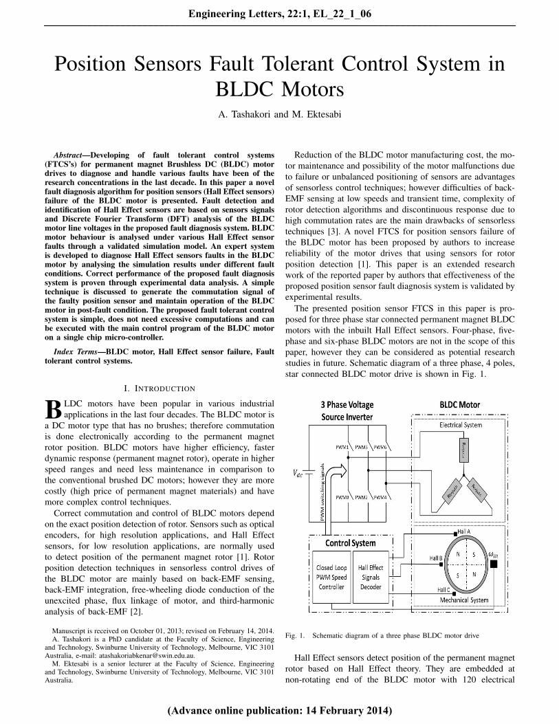
The presented position sensor FTCS in this paper is pro-posed for three phase star connected permanent magnet BLDCmotors with the inbuilt Hall Effect sensors. Four-phase, five-phase and six-phase BLDC motors are not in the scope of thispaper, however they can be considered as potential researchstudies in future. Schematic diagram of a three phase, 4 poles,star connected BLDC motor drive is shown in Fig. 1.
Fig. 1. Schematic diagram of a three phase BLDC motor drive
Hall Effect sensors detect position of the permanent magnetrotor based on Hall Effect theory. They are embedded atnon-rotating end of the BLDC motor with 120 electrical
Engineering Letters, 22:1, EL_22_1_06
(Advance online publication: 14 February 2014)
______________________________________________________________________________________

degree phase difference to detect the rotor position. Hall Effectsensor’s output is high (logic ‘1’) or low (logic ‘0’) as the rotormagnetic poles N or S passes near the sensor. Therefore outputof each sensor is high for 180 electrical degree and is low forthe next 180 electrical degree with respect to the rotor positionduring one full electrical rotation of the BLDC motor. Correctvoltage space vectors for switching of the three phase VoltageSource Inverter (VSI) drive of the BLDC motor are chosen bydecoding Hall Effect signals. Ideal phase currents, back-EMFand commutation (Hall Effect) signals are shown in Fig.2.
Fig. 2. Ideal waveforms of a three phase BLDC motor
Since the voltage space vectors are chosen by decodingof the Hall Effect signals to drive the VSI; any failure ofHall Effect sensor effects directly on the applied voltagesto the BLDC motor and degrades the motor performance.Implementing FTCS’s increase reliability of the electric motordrives in post-fault detection. Fault tolerant control systemsmainly are responsible to detect and identify the fault, isolatethe faulty section and take the appropriate remedial actionto keep the system working with the maximum possibleefficiency in the post-fault condition [4].
Signal analysis, model based and knowledge based methodsare the main techniques for fault diagnosis in the BLDC motordrives [5]. In the signal analysis based methods, fault is de-tected and identified through comparison of the BLDC motorsignals with the ideal situation. Therefore there is no needfor an accurate dynamic model of the motor. Signal analysisfault diagnosis methods are generally slower than other twomethods. Fault diagnosis in model based methods is quite fastand can be used for online fault detection; however the exactmathematical model of the BLDC motor is needed. Modelbased observers are popularly used in fault diagnosis systems;however fault detection residuals are influenced not only bysystem faults but also by disturbances and model uncertainties
[6]. Since uncertainties, disturbances or noise in system areunknown and cannot be modelled mathematically; thereforethere is always a difference between the mathematical modelresults and actual system performance that can generates falsefault detections in model based systems [7]. In expert systems,fuzzy or neural network controllers are developed based onthe knowledge of system [5]. The knowledge is collectedand analysed either through an experienced engineer with athorough understanding of the system, or via comprehensivestudy of the system dynamics through a validated simulationmodel [4]. This paper presents a knowledge based faultdiagnosis system based on signal analysis methods for HallEffect sensor breakdown of the BLDC motor.
Flaws in the Hall Effect sensor’s core due to corrosion,cracks, residual magnetic fields and core breakage; effect oftemperature variations on the magnetic properties of the ferritecore; effect of mechanical shocks on orientation of the inducedmagnetic field in the sensor; and changes in the bias currentof the sensor are main faults that may result in failure ofHall Effect sensors in the BLDC motors [8]. Unbalancedpositioning of Hall Effect sensors inside the BLDC motorincreases the low frequency harmonics in torque ripples anddegrades the overall drive performance of the motor [9],however it does not in the position sensor failure and is notin the scope of this paper.
Few research works are reported on FTCS for Hall Effectsensor failure in the BLDC motors. Major possible sensorfaults in the propulsion system of an interior-permanent-magnet-motor (IPMM)-based electric vehicle are discussedand remedial strategies are proposed [10]. Fault in positionsensors are detected through difference between the calculatedrotor angle and the actual rotor angle by a sensorless algorithmbased on extended EMF in rotating reference frame. Shiftto the sensorless control mode of permanent-magnet-motoris proposed as a remedial strategy to rectify the fault. Com-plexities of permanent magnet synchronous motor’s sensorlesscontrol schemes and transition algorithms to sensorless modeare the main drawbacks of the proposed method. Behaviour ofthe BLDC motor under position sensors faults in lunar roverwheel application is analysed through simulation model [11].Effects of Hall Effect sensor faults on switching signals of VSIand phase current waveforms are presented. However there isnot any discussion on the simulation results, the fault diagnosistechnique and remedial strategies in the mentioned paper.
An intelligent fault tolerant control system for Hall Effectsensor failure in the BLDC motors is presented in this paper.BLDC motor behaviour is analysed under various positionsensor fault conditions on the next section. Hall Effect sensorfault diagnosis algorithm for the BLDC motor and a novel andsimple remedial strategy to rectify the fault are presented anddiscussed on the following sections. Finally effectiveness ofthe proposed fault diagnosis algorithm is investigated throughexperiment.
II. BLDC MOTOR BEHAVIOUR ANALYSIS UNDER HALLEFFECT SENSOR FAULTS
To find an algorithm to detect and identify the faultysensor, first it is necessary to study behaviour of the BLDC
Engineering Letters, 22:1, EL_22_1_06
(Advance online publication: 14 February 2014)
______________________________________________________________________________________
motor under various position sensor faults through a validatedsimulation model. Therefore the BLDC motor drive using aclosed loop digital Pulse Width Modulation (PWM) speedcontroller is modelled in Simulink. A low voltage three phasepermanent magnet BLDC motor is used as a practical testrig to validate simulation model of the motor. Low voltagedevelopment board of microchip using PIC18F4231 micro-controller is programmed to control the BLDC motor. Thecontrol board has an in-built over current protection circuitand the inverter section consists of three half-bridge gatedrivers using MOSFETs. High frequency PWM control signalis applied to all the switches of the inverter. Experimental testrig of the BLDC motor is shown in Fig. 3.
Fig. 3. Experimental test rig of the BLDC motor
The experimental BLDC motor specifications, given inTable I, have been used in the motor simulation model. Thethree phase VSI drive of the BLDC motor is simulated usingMOSFET switches same as the experimental motor drive.Duty cycle of PWM signal is adjusted by a ProportionalIntegral (PI) controller based on speed error of the motor. Anembedded code is written in Simulink model to generate thehigh frequency duty cycle controlled PWM signal [1].
TABLE ISPECIFICATIONS OF THE EXPERIMENTAL BLDC MOTOR
Description Value Unit
DC voltage 24 V
Rated speed 3000 RPM
Rated Torque 0.28 N.m
Phase resistance 2.015 ohm
Phase inductance 4.60 mH
Inertia 4.43e-6 kg.m2
Torque constant 0.069 N.m/A
Poles 8 -
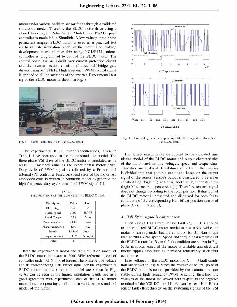
Both the experimental motor and the simulation model ofthe BLDC motor are tested at 2000 RPM reference speed ofcontroller under 0.1 N.m load torque. The phase A line voltageand its corresponding Hall Effect signal for the experimentalBLDC motor and its simulation model are shown in Fig.4. As can be seen in the figure, simulation results are in agood agreement with experimental data of the BLDC motorunder the same operating condition that validates the simulatedmodel of the motor.
Fig. 4. Line voltage and corresponding Hall Effect signal of phase A ofthe BLDC motor
Hall Effect sensor faults are applied to the validated sim-ulation model of the BLDC motor and output characteristicsof the motor such as line voltages, speed and torque char-acteristics are analysed. Breakdown of a Hall Effect sensoris divided into two possible conditions based on the outputsignal of the sensor. Sensor’s output is considered to be eitherconstant high (logic ‘1’), sensor is short circuit, or constant low(logic ‘0’), sensor is open circuit [1]. Therefore sensor’s signaldoes not change according to the rotor position. Behaviour ofthe BLDC motor is presented and discussed for both faultyconditions of the corresponding Hall Effect position sensor ofphase A (Ha = 0 and Ha = 1).
A. Hall Effect signal is constant zero
Open circuit Hall Effect sensor fault Ha = 0 is appliedto the validated BLDC motor model at t = 0.5 s, while themotor is running under healthy condition for 0.1 N.m torqueload at 2000 RPM speed. Speed and torque characteristics ofthe BLDC motor for Ha = 0 fault condition are shown in Fig.5. As is shown speed of the motor is unstable and electricaltorque ripples amplitude is increased remarkably after faultoccurrence.
Line voltages of the BLDC motor for Ha = 0 fault condi-tion are shown in Fig. 6. Since the voltage of neutral point ofthe BLDC motor is neither provided by the manufacturer norstable during high frequency PWM switching; therefore linevoltages of the motor are sensed with respect to the negativeterminal of the VSI DC link [1]. As can be seen Hall Effectsensor fault effect directly on the switching signals of the VSI
Engineering Letters, 22:1, EL_22_1_06
(Advance online publication: 14 February 2014)
______________________________________________________________________________________

Fig. 5. Speed and torque characteristics of the BLDC motor for Ha = 0
and change pattern of the applied line voltage of the BLDCmotor.
Fig. 6. Line voltages of the BLDC motor for Ha = 0
Various Hall Effect sensor faults are applied to the BLDCmotor simulation model and effect of position sensor faults onthe switching signals of VSI are summarized in Table II. EachHall Effect sensor fault cause two switching signals of the VSIto be constant zero that can be interpreted as open circuit faultsof two VSI switches at the same time. For instance underHa = 0 fault condition, corresponding switching signals ofPWM1 and PWM4 are constant zero (those switches areopen circuit). Any VSI switching signals variations directlyeffect on the applied voltages to the BLDC motor, increasesthe torque ripples and degrade the motor performance.
B. Hall Effect signal is constant one
Short circuit Hall Effect sensor fault Ha = 1 is appliedto the validated BLDC motor model at t = 0.5 s, while the
TABLE IISENSORS FAULT EFFECT ON THE VSI SWITCHING SIGNALS
Fault type Effected switching Switches statussignals of the VSI
Ha = 0 PWM1 , PWM4 Open
Ha = 1 PWM5 , PWM0 Open
Hb = 0 PWM3 , PWM0 Open
Hb = 1 PWM1 , PWM2 Open
Hc = 0 PWM5 , PWM2 Open
Hc = 1 PWM3 , PWM4 Open
motor is running under healthy condition for 0.1 N.m torqueload at 2000 RPM speed. Speed and torque characteristics ofthe BLDC motor for Ha = 1 fault condition are similar toHa = 0 fault condition. Torque ripples amplitude is increasedand the BLDC motor is not stable after fault occurrence.
Although speed and torque responses of the BLDC motorfor Ha = 1 are similar to the ones for Ha = 0 fault condition;however affected switching signals of the VSI is different.Switching signals PWM0 and PWM5 are constant zero forHa = 1 fault condition. Therefore applied voltages to theBLDC motor are totally different for Ha = 1 fault conditioncompare to the Ha = 0 fault. Line voltages of the BLDCmotor for Ha = 1 fault condition are shown in Fig. 7.
Fig. 7. Line voltages of the BLDC motor for Ha = 1
III. FAULT DIAGNOSIS
Hall Effect signals (commutation signals) of BLDC motorare either high or low according to the electrical degreeposition of permanent magnet rotor. Correct voltage spacevectors are chosen according to the electrical position of rotorby decoding the commutation signals. Hall Effect signals andconducting switches of the VSI according to the permanentmagnet rotor position are summarized in Table III.
There is no position of permanent magnet rotor that all threehall signals being one or zero at a same time. Addition ofcommutation signals are either one or two at any electricalangle position of the rotor. Therefore any failure of Hall
Engineering Letters, 22:1, EL_22_1_06
(Advance online publication: 14 February 2014)
______________________________________________________________________________________
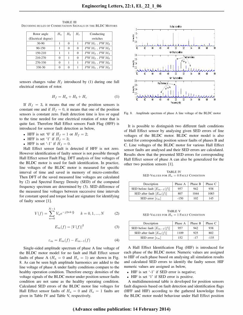
TABLE IIIDECODING RULES OF COMMUTATION SIGNALS IN THE BLDC MOTORS
Rotor angle Ha Hb Hc Conducting(Electrical degree) switches
30-90 1 0 1 PWM1 , PWM2
90-150 1 0 0 PWM1 , PWM4
150-210 1 1 0 PWM3 , PWM4
210-270 0 1 0 PWM3 , PWM0
270-330 0 1 1 PWM5 , PWM0
330-30 0 0 1 PWM5 , PWM2
sensors changes value Hf introduced by (1) during one fullelectrical rotation of rotor.
Hf = Ha +Hb +Hc (1)
If Hf = 3, it means that one of the position sensors isconstant one and if Hf = 0, it means that one of the positionsensors is constant zero. Fault detection time is less or equalto the time needed for one electrical rotation of rotor that isquite fast. Therefore Hall Effect sensors Fault Flag (HFF) isintroduced for sensor fault detection as below,
• HFF is set ‘0’ if Hf = 1 or Hf = 2;• HFF is set ‘1’ if Hf = 3;• HFF is set ‘-1’ if Hf = 0.Hall Effect sensor fault is detected if HFF is not zero.
However identification of faulty sensor is not possible throughHall Effect sensor Fault Flag. DFT analysis of line voltages ofthe BLDC motor is used for fault identification. In practice,line voltages of the BLDC motor is measured for specificinterval of time and saved in memory of micro-controller.Then DFT of the saved measured line voltages are calculatedby (2) and Spectral Energy Density (SED) of the computedfrequency spectrum are determined by (3). SED difference ofthe measured line voltages between successive time intervalsfor constant speed and torque load are signature for identifyingof faulty sensor [1].
V (f) =N−1∑n=0
Vne−j2πk n
N k = 0, 1, ..., N (2)
Em(f) = |V (f)|2 (3)
εm = Em(f)− Em−1(f) (4)
Single-sided amplitude spectrum of phase A line voltage ofthe BLDC motor model for no fault and Hall Effect sensorfaults of phase A (Ha = 0 and Ha = 1) are shown in Fig.8. As can be seen high amplitude harmonics are added to theline voltage of phase A under faulty conditions compare to thehealthy operation condition. Therefore energy densities of thevoltage signals of the BLDC motor under position sensor faultscondition are not same as the healthy operating condition.Calculated SED errors of the BLDC motor line voltages forHall Effect sensor faults of Ha = 0 and Ha = 1 faults aregiven in Table IV and Table V, respectively.
Fig. 8. Amplitude spectrum of phase A line voltage of the BLDC motor
It is possible to distinguish two different fault conditionsof Hall Effect sensor by analysing given SED errors of linevoltages of the BLDC motor. BLDC motor model is alsotested for corresponding position sensor faults of phases B andC. Line voltages of the BLDC motor for various Hall Effectsensor faults are analysed and their SED errors are calculated.Results show that the presented SED errors for correspondingHall Effect sensor of phase A can also be generalized for theother two position sensors [1].
TABLE IVSED VALUES FOR Ha = 0 FAULT CONDITION
Description Phase A Phase B Phase C
SED before fault [Em−1(f)] 957 942 938
SED after fault [Em(f)] 807 1044 1083
SED error [εm] -150 102 145
TABLE VSED VALUES FOR Ha = 1 FAULT CONDITION
Description Phase A Phase B Phase C
SED before fault [Em−1(f)] 957 942 938
SED after fault [Em(f)] 1109 925 802
SED error [εm] 152 -17 -135
A Hall Effect Identification Flag (HIF) is introduced foreach phase of the BLDC motor. Numeric values are assignedto HIF of each phase based on analysing all simulation resultsand calculated SED errors to identify the faulty sensor. HIFnumeric values are assigned as below,
• HIF is set ‘-1’ if SED error is negative;• HIF is set ‘1’ if SED error is positive.A multidimensional table is developed for position sensors
fault diagnosis based on fault detection and identification flags(HFF and HIF) according to the gathered knowledge fromthe BLDC motor model behaviour under Hall Effect position
Engineering Letters, 22:1, EL_22_1_06
(Advance online publication: 14 February 2014)
______________________________________________________________________________________

sensor faults. In addition to the simplicity of fault diagnosismethod, there is also no need to know exact pattern of theBLDC motor line voltages for different speed and torque loadsin advance. Multidimensional knowledge based table for HallEffect sensor fault diagnosis of the BLDC motor is shownin Table VI [1]. Therefore fault occurrence and fault typeare detected as soon as HFF is not zero and faulty sensoris detected based on HIF values of each phase according tothe Table VI.
TABLE VIPROPOSED KNOWLEDGE BASED TABLE FOR POSITION SENSOR FAULTS
DIAGNOSIS
Fault type HIF HIF HIF HFFphase A phase B phase C
No fault X X X 0
HA = 0 -1 1 1 -1
HA = 1 1 -1 -1 1
HB = 0 1 -1 1 -1
HB = 1 -1 1 -1 1
HC = 0 1 1 -1 -1
HC = 1 -1 -1 1 1
IV. EXPERIMENTAL RESULT
The proposed fault diagnosis algorithm of the BLDC motoris investigated through experimental test rig. Low voltage (LV)development board of microchip using PIC18F2431 micro-controller has been modified as shown in Fig. 9 to test theHall Effect sensor faults of the BLDC motor. Both shortcircuit and open circuit faults of Hall Effect sensors have beenimplemented to the experimental BLDC motor and the resultsare analysed.
Fig. 9. Modified LV development board of microchip
Open circuit fault of Hall sensor of phase A (Ha = 0)is applied to the experimental test motor when the motorwas running at 2000 RPM under 0.1 N.m torque load. Speedoscillation and high acoustic noise of the BLDC motor are thefirst observations after fault occurrence. Line voltages of theexperimental BLDC motor under Ha = 0 fault condition areshown in Fig. 10. As can be seen pattern of the BLDC motorline voltages are distorted compared to the healthy operatingcondition. However same as the presented simulation results,the most variations are belong to the phases A and B.
Fig. 10. Line voltages of the experimental BLDC motor during Ha = 0fault condition
Open circuit fault of Hall sensor of phase A (Ha = 1)is applied to the experimental test motor when the motorwas running at 2000 RPM under 0.1 N.m torque load. Linevoltages of the experimental BLDC motor under Ha = 1 faultcondition are shown in Fig. 11. As can be seen pattern of theline voltages are totally different compared to the Ha = 0fault condition.
Fig. 11. Line voltages of the experimental BLDC motor during Ha = 1fault condition
As is discussed and presented in Table II, each Hall Effectsensor fault results in loosing specific switching signals of theVSI. Six LED lights are implemented on the control board toshow the status of the switching signals. If the switching signalis zero, then the corresponding LED light is turned off and
Engineering Letters, 22:1, EL_22_1_06
(Advance online publication: 14 February 2014)
______________________________________________________________________________________

vice versa. Status of the LED lights for open circuit and shortcircuit faults of the Hall Effect sensor of phase A are shownin Fig. 12. As can be seen switching signals PWM1 andPWM4 for open circuit fault condition and switching signalsPWM0 and PWM5 for short circuit fault condition are zero.Therefore effects of Hall Effect sensor faults on switchingsignals of the VSI that are presented in Table II are validatedthrough experiment.
Fig. 12. Status of switching LED lights on the control board under positionsensor faults of phase A: (a) Open circuit fault (b) Short circuit fault
Single-sided amplitude spectrum of phase A line voltagesof the experimental BLDC motor under no fault, Hall Effectsensor open circuit fault (Ha = 0) and Hall Effect sensorshort circuit fault (Ha = 1) conditions are plotted in Fig. 13.As can be seen same as the case in simulation results, highamplitude harmonics are added to the line voltage of phaseA of the experimental BLDC motor under Hall Effect sensorfault conditions. Therefore spectral energy densities of the linevoltages are not same for different position sensor faults in theBLDC motor drive.
Fig. 13. Amplitude spectrum of phase A line voltage of the BLDC motor
Spectral energy density errors of the experimental BLDCmotor line voltages under Ha = 0 and Ha = 1 fault conditions
are calculated and given in Tables VII and VIII. As can be seenthe assigned numeric values to the Hall Effect identificationflag based on practical SED errors is as same as the simulationones presented in Tables IV and V. The experimental SEDerrors are not as large values as the simulation SED errors dueto the inbuilt over current protection circuit of the controllerboard.
TABLE VIISED VALUES FOR EXPERIMENTAL Ha = 0 FAULT CONDITION
Description Phase A Phase B Phase C
SED before fault [Em−1(f)] 314.9870 322.1711 322.3580
SED after fault [Em(f)] 301.1294 329.6414 369.2658
SED error [εm] -13.8576 7.4703 46.9078
TABLE VIIISED VALUES FOR EXPERIMENTAL Ha = 1 FAULT CONDITION
Description Phase A Phase B Phase C
SED before fault [Em−1(f)] 314.9870 322.1711 322.3580
SED after fault [Em(f)] 330.2032 319.5225 310.2840
SED error [εm] 15.2162 -2.6486 -12.074
The low voltage experimental BLDC motor is also testedunder open circuit and short circuit faults of the other HallEffect sensors, corresponding sensors of phase B and C, andtheir experimental results are analysed. Calculated experimen-tal SED errors of the line voltages prove the fault diagnosisalgorithm and validate the knowledge based fault identificationtable, Table VI, developed through the simulation model.
V. REMEDIAL STRATEGY
The Faulty Hall Effect sensor must be isolated and its signalshould be disconnected from the BLDC motor controller. Asimple technique is proposed to generate the Hall Effect signalof the faulty sensor by micro-controller. In this technique,corresponding commutation signal of the faulty sensor isgenerated by implementing 120 electrical degree delays toone of the other two available Hall Effect sensors. A simpleequation has been introduced to calculate the time that isneeded for the BLDC motor rotor to pass one electricaldegree [3]. If the BLDC motor speed does not change duringcommutation intervals (it is assumed that the controller keepsthe motor speed constant), the time of one electrical degreerotation of the BLDC motor can be calculated by (5), whereP is the pole numbers and ωref is the reference speed ofthe motor in RPM. Effectiveness of the proposed techniqueto calculate the correct time delays and generate the correctcommutation signals in the BLDC motors is proved throughsimulation and experiment [3].
t =1
P2 (6 ∗ ωref )
(5)
An embedded code is written and implemented in Simulinkmodel of the BLDC motor to test performance of the proposedFTCS. Open circuit fault Ha = 0 is applied to the simulationmodel at t = 0.5 s while the motor is running at 2000 RPM
Engineering Letters, 22:1, EL_22_1_06
(Advance online publication: 14 February 2014)
______________________________________________________________________________________

under 0.1 N.m torque load. Speed characteristics of the BLDCmotor with the implemented fault tolerant control system isshown in Fig. 14.
Fig. 14. Speed response of the fault tolerant controlled BLDC motor drive
Fault is detected, identified through calculating HFF andHIF of each phase. Fault diagnosis time in simulation modelis about 0.113 second which is quite fast and acceptablefor motor drives. Faulty sensor signal are generated by thecontroller that maintains the proper performance of the BLDCmotor in the post-fault condition. Simulation results showeffectiveness of the proposed remedial strategy for Hall Effectsensors breakdown in the BLDC motors.
VI. CONCLUSION
In this paper, a fault tolerant control system for Hall Effectposition sensors failure in the BLDC motor drives is presented.Behaviour of the BLDC motor is analysed under variousposition sensor faults conditions through a validated simulationmodel. It is shown that any position sensor faults effectdirectly on the applied line voltages of the BLDC motor.Fault occurrence is detected through Hall Effect sensor signalsanalysis. A knowledge based table is developed to identifythe faulty sensor based on DFT analysis of the BLDC motorline voltages. Since faulty sensor is identified through spectraldensity errors of the line voltages of the motor; the exactpre-knowledge of line voltages pattern under various workingcondition is not needed. This advantage of the proposedFTCS makes it useful for application with frequent changeof speed and load torque such as electric vehicles. A simpletechnique is proposed to generate the signal of faulty sensorby implementing the time delays between Hall Effect sensorsignals in post-fault condition. Effectiveness of the proposedfault diagnosis algorithm and the proposed knowledge basedtable for Hall Effect sensors breakdown are investigated anddiscussed through experiments. Correctness of the proposedfault diagnosis algorithm is proved by the experimental results.
REFERENCES
[1] A. Tashakori and M. Ektesabi, “A simple fault tolerant control system forhall effect sensors failure of bldc motor,” in Proceeding of the 8th IEEEConference on Industrial Electronics and Applications (ICIEA 2013),(Melbourne, VIC), pp. 1011–1016, 2013.
[2] T.-H. Kim and M. Ehsani, “Sensorless control of the bldc motors fromnear-zero to high speeds,” IEEE Transactions on Power Electronics,vol. 19, no. 6, pp. 1635–1645, 2004.
[3] A. Tashakori and M. Ektesabi, “Stability analysis of sensorless bldcmotor drive using digital pwm technique for electric vehicles,” inProceeding of 38th Annual Conference on IEEE Industrial ElectronicsSociety, IECON 2012, pp. 4898–4903, October 2012.
[4] A. Tashakori and M. Ektesabi, “Fault diagnosis of in-wheel bldc motordrive for electric vehicle application,” in In proceeding of the 2013 IEEEIntelligent Vehicles Symposium, (Gold Coast, Australia), pp. 925–930,June 23-26 2013.
[5] X.-Q. Liu, H.-Y. Zhang, J. Liu, and J. Yang, “Fault detection anddiagnosis of permanent-magnet dc motor based on parameter estimationand neural network,” IEEE Transactions on Industrial Electronics,vol. 47, no. 5, pp. 1021–1030, 2000.
[6] Z. Wang, R. Schittenhelm, M. Borsdorf, and S. Rinderknecht, “Ap-plication of augmented observer for fault diagnosis in rotor systems,”Engineering Letters, vol. 21, no. 1, pp. 10–17, 2013.
[7] S. Mondal, G. Chakraborty, and K. Bhattacharyya, “Unknown input highgain observer for fault detection and isolation of uncertain systems,”Engineering Letters, vol. 17, no. 2, pp. 121–127, 2009.
[8] E. Balaban, A. Saxena, P. Bansal, K. Goebel, and S. Curran, “Modeling,detection, and disambiguation of sensor faults for aerospace applica-tions,” IEEE Sensors Journal, vol. 9, no. 12, pp. 1907–1917, 2009.
[9] N. B. Samoylenko, Q. C. Han, and J. Jatskevich, “Dynamic performanceof brushless dc motors with unbalanced hall sensors,” IEEE Transactionson Energy Conversion, vol. 23, no. 3, pp. 752–763, 2008.
[10] Y.-S. Jeong, S.-K. Sul, S. Schulz, and N. Patel, “Fault detection and fault-tolerant control of interior permanent-magnet motor drive system forelectric vehicle,” IEEE Transactions on Industry Applications, vol. 41,no. 1, pp. 46–51, 2005.
[11] L. Wang, J. Liu, and X. Wu, “Fault analysis on driving motors oflunar rover wheels,” in Proceeding of the International Conference onElectrical Machines and Systems, ICEMS 2011, (Beijing, China), Aug2011.
Engineering Letters, 22:1, EL_22_1_06
(Advance online publication: 14 February 2014)
______________________________________________________________________________________