possibilities of analysis of condition and …kones.eu/ep/2016/vol23/no4/209-216_00_j_o_kones... ·...
TRANSCRIPT
Journal of KONES Powertrain and Transport, Vol. 23, No. 4 2016
POSSIBILITIES OF ANALYSIS OF CONDITION AND REPAIR OF COMMON-RAIL SYSTEM INJECTORS
Wojciech Karpiuk, Mateusz Bor, Rafał Smolec
Poznan University of Technology Piotrowo 3, 61-138, Poznan, Poland
tel.: +48 61 6475993, fax: + 48 61 6652204 e-mail: [email protected]
Abstract
A wide use of common-rail injection systems in vehicles made it necessary to develop effective methods of diagnosing and repair of their subassemblies. The paper presents problems connected with diagnosing of malfunctions and regeneration of common-rail system injectors with the use of testing tables. Due to precise workmanship and strong forces, the systems are particularly exposed to damage most often caused by the application of fuels of inadequate quality. Early detection of damage symptoms may contribute to considerable decrease of costs of repair without entailing any failures of other components of the system. The authors discuss the most common methods of evaluation of the condition allowing a quick and explicit identification, whether a given injector has been damaged or not. Further deliberations lead to the determination of possible regeneration of individual generation systems of various manufacturers. The authors also present basic activities of the regeneration process and tests made with the use of testing tables. The work presents results of tests performed on a new injector with the use of testing equipment of various manufacturers. Discussion on obtained results leads to conclusions that, due to little recurrence and insufficient accuracy of measurements, possibilities of clear evaluation of technical condition of injectors is greatly limited.
Keywords: common-rail, diagnostics, testing tables, injectors
1. Introduction
Common-rail (CR) injection systems have been commonly used in diesel engines for 20 years. The first unit to use common rail type direct injection was Fiat UniJet engine of the capacity of 1.9 dm3. Undoubtedly, the greatest advantages of the system included its ability to achieve high pressure in the accumulator regardless of the crankshaft position and its speed. Further development, which was directly connected with the implementation of more and more stringent exhaust gas emission standards, led to an increase in the precision of fuel dosage and introduced a division of injection into several subdoses (currently up to 10) during one cycle of the engine operation. The diagram (Fig. 1) presents the engine subassemblies used for the engine to comply with the requirements set by the European standards relating to exhaust emissions. Elements introduced for the compliance with the Euro 4 standard are marked blue and equipment installed in the systems complying with the Euro 5 standard is marked orange.
Diesel engines can achieve a low level of exhaust emissions owing to the use of aftertreatment systems and the optimization of the combustion processes. The latter was possible mainly owing to the increase of the precision of injection by: – the increase of pressure in the system, from 135 MPa to 2 500 MPa (Bosch HADI),– minimization of the inertia of the moving elements by a decrease in their number and size,– use of piezoelectric control components,– division of a fuel dose into parts.
Manufacturers of injection systems for passenger vehicles estimate their life at the level of300,000-400,000 km. Components that are most exposed to wear as a result of cooperation include precision pairs of the high-pressure pump (piston-cylinder and cam-pusher) and injectors (valve
ISSN: 1231-4005 e-ISSN: 2354-0133 DOI: 10.5604/12314005.1217208

W. Karpiuk, M. Bor, R. Smolec
Fig. 1. Components of the common rail injection system [7]
ball-socket and needle-body). This is natural wear resulting from exertion of high forces between the cooperating elements as well as other destructive phenomena such as cavitation found within the area of the nozzles [6].
However, unfitness for use often occurs before the end of the service life assumed by the manufacturer of the system. The most frequent cause of damage to the injection equipment is inadequate quality of the fuel understood as: – presence of solid contaminants, – inappropriate viscosity and density of the fuel, – presence of undesired chemical compounds (e.g. sulphur contributing to corrosion).
In common-rail systems fuel is also a cooling and a greasing medium. A change of the viscosity prevents formation of a greasing film that sufficiently separates the cooperating surfaces. The presence of contamination is caused, to a great extent, by the use of low quality fuel filters and failure to adhere to their changing intervals. Fig. 2 shows examples of damage to the injectors as a result of the use of fuel of inadequate quality.
Fig. 2. Examples of damage to CRI Bosch injector components – damage caused by a foreign object (1), seizure of
the needle (2), corrosion within the pusher area (3) [7] Defects of the accumulator system subassemblies are also caused by the use of bad design
solutions particularly visible in the first generations of injection pumps manufactured by Delphi, Siemens and Bosch (Fig. 3). Examples of typical damage connected with the pump structure include [5]:
210
Possibilities of Analysis of Condition and Repair of Common-Rail System Injectors
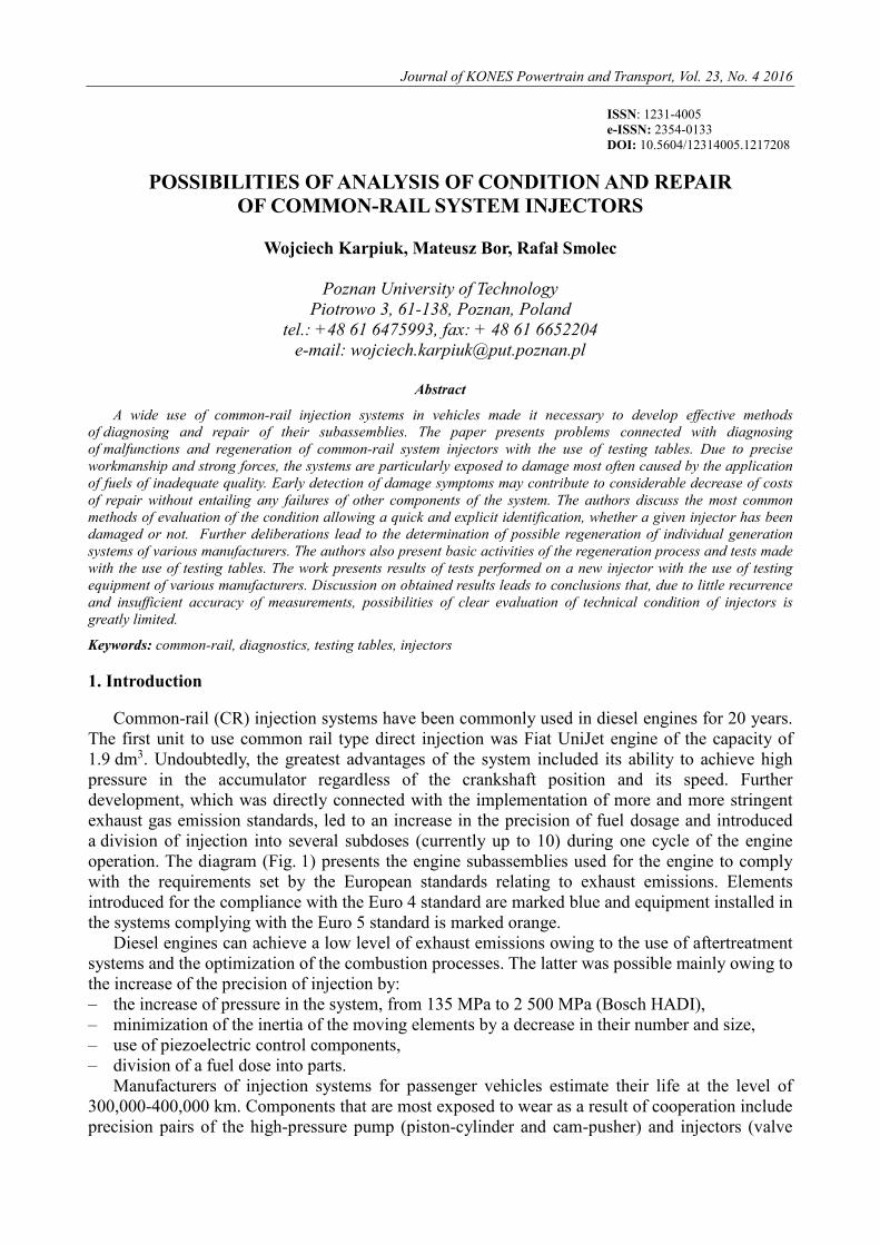
– in the case of Bosch CP1 pump (Fig. 3a) – wear connected with the pump design. Because of the revolution of the pump shaft, the pusher (1) is positioned under an angle to the cam (2), which leads to an additional force component perpendicular to the piston axis. The force is transferred entirely by the pusher and, in particular, its elements, i.e. the plate (3) and the basket (4). If fuel of inadequate quality is used or, if for some reasons less fuel is supplied (e.g. seized fuel supply valve) inside the pump, the friction coefficient increases on the surface of contact between the pusher and the cam. This leads to a situation, in which the pusher is additionally loaded by the increased friction force component
– in the case of Delphi DFP1 pump (Fig. 3b) – damage to the roll (1) cooperating with the track (2) and the piston (3). In normal conditions of operation, rolling friction occurs between the components. As a result of the use of fuel of inadequate quality or a start-up following a long period of standstill, the roll may slide. This results in loss of the material in the form of particles (φ <2µm), which cause further damage to the system. Most often chips, owing to their small diameters, get into the injectors and damage the needle-body pair. Thus, during the repair of the injectors and the pump, one should absolutely replace all ducts of the fuel system and clean the fuel tank. The system is also worn as a result of an abrupt cam lift, which leads to the occurrence of strong cyclical impact stresses,
– in the case of Continental pumps (Fig. 3c) – seizure of blades (1) of the pressing pump. The structure of the pressing pump is similar to that of the Delphi pump solution, however, due to the low weight of the blades and tight fitting in the disc, blades often tend to seize, which is favoured by the contamination in the fuel. In case of surface contamination, centrifugal force causing the radial pushing of the blade is insufficient. Decrease in the capacity of the pressure pump leads to insufficient greasing of the pumping sections, which, as a result of temperature increase, may cause the same to seize.
Fig. 3. Occurrence of damage in Bosch (a), Delphi (b) and Continental injection pump components (c)
The workshop practice shows that an injector is a component of common-rail systems that is
most often exposed to damage. Due to costly replacement of the equipment subassemblies, methods have been developed for diagnosis and regeneration of the system parts. In numerous cases, it is possible to limit the costs of repair up to 40% of the price of a new element to preserve correct parameters of operation. Presently, there are two CR system manufacturers (Bosch and Delphi) offering complete regeneration of the injectors. 2. Diagnosing and repair of injectors
Common use of common rail type systems in passenger vehicles contributed to the development of numerous diagnosing methods. They include, among others [3]: – measurement of electrical signals, – overflow test, – examination of fuel spray diffusion, – determination of parameters with the use of testing tables.
211
W. Karpiuk, M. Bor, R. Smolec
2.1. Evaluation of the technical condition
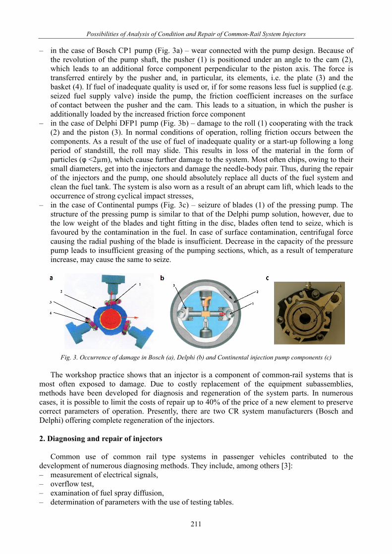
Any damage to electrical circuits of an injector can be found by measuring the coil resistance and inductance (Fig. 4). Therefore, a universal meter is connected to an electrical connection of the injector and the injector parameters are determined. An operable electromagnetic injector is characterized by its coil resistance of 0.33 Ω and inductance of 200-300 μH [3]. The resistance between the connection and the body should be infinitely high, which proves absence of any short-circuit in the electrical system. For injectors with a piezoelectric adjuster, the capacity of the piezoelectric stack is determined with its value of approx. 3 μF.
The course of signals controlling the injector operation and change of pressure of the fuel pressure sensor in the accumulator are determined with the use of an oscilloscope. The oscilloscope is connected with the use of current clamps to cables. During operation of the engine, the oscilloscope screen displays recorded courses of signals evaluating the current and voltage values at a given point as well as the course of their characteristics. In case of a considerable change of the curves, damage to the injector may be identified.
Fig. 4. Measurement of inductance and resistance of the injector coil with the use of a mustimeter [3]
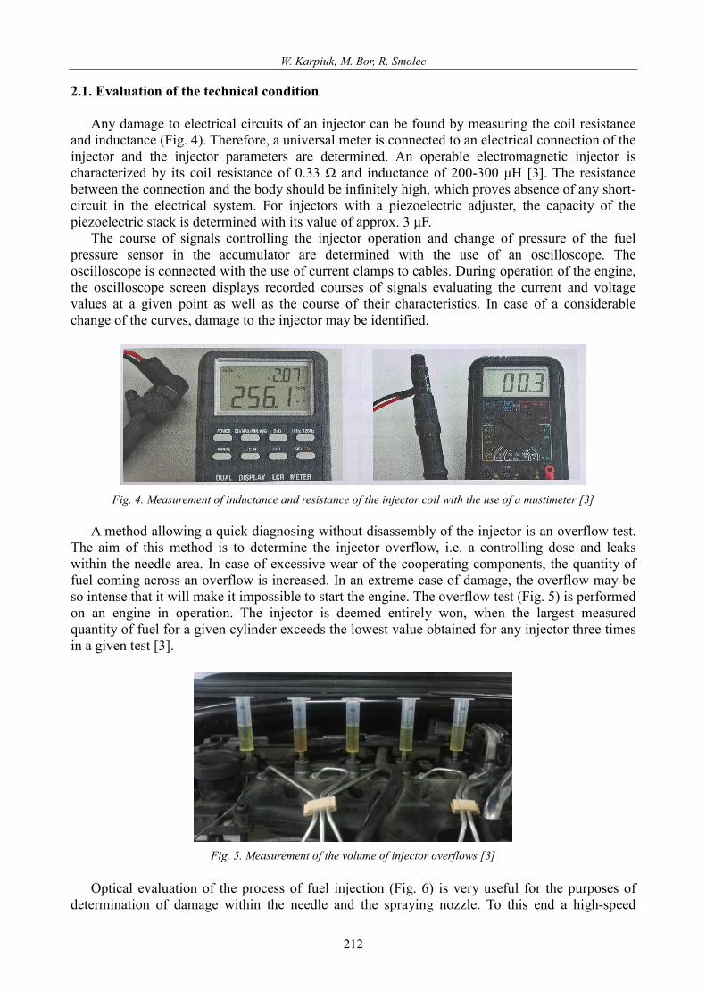
A method allowing a quick diagnosing without disassembly of the injector is an overflow test.
The aim of this method is to determine the injector overflow, i.e. a controlling dose and leaks within the needle area. In case of excessive wear of the cooperating components, the quantity of fuel coming across an overflow is increased. In an extreme case of damage, the overflow may be so intense that it will make it impossible to start the engine. The overflow test (Fig. 5) is performed on an engine in operation. The injector is deemed entirely won, when the largest measured quantity of fuel for a given cylinder exceeds the lowest value obtained for any injector three times in a given test [3].
Fig. 5. Measurement of the volume of injector overflows [3]
Optical evaluation of the process of fuel injection (Fig. 6) is very useful for the purposes of
determination of damage within the needle and the spraying nozzle. To this end a high-speed
212

Possibilities of Analysis of Condition and Repair of Common-Rail System Injectors
camera is used, which makes it possible to observe the propagation of the spray for a given injection. The resulting fuel sprays should be characterized by similar parameters (range, spray cone opening angle, surface). In case of damage within the spraying nozzle or the needle, one can observe a decrease in the stream range or change of its shape. A change of propagation of one of the sprays provides information as to the damage in the injector nozzle area [4].
Fig. 6. Propagation of the fuel spray for an 8-hole injector [4]
2.2. Regeneration
Presently, repair technology provides for a complete three-stage regeneration of injectors: – Bosch electromagnetic 1st and 2nd generation injectors, – Delphi electromagnetic 1st and 2nd generation injectors – except for the controlling coil, which
is unavailable. Part regeneration involving the replacement of the spraying nozzle and a possible adjustment
applies to the following injectors: – Continental piezoelectric injectors, – Denso electromagnetic injectors.
Additionally, by the end of 2016, technology of repair for he Bosch piezoelectric injectors will have been introduced.
Testing tables are tools used for diagnostics and repair of injectors. The table frame has a pump set in it, driven by an inverter and equipped with an electronic operation control system. The pump supplies the tested injectors, for which, through a user interface, it is possible to smoothly control the pressure in the supply rail, the injection frequency and the injection time. Injectors are placed in measuring cylinders, into which fuel is injected and, then, dosed. Most of the testing tables can be used for testing the injector electrical elements as well as for the overflow tests. During verification of the condition, the following tests are performed as standard: – leak test – (fuel is pumped under the system maximum pressure, the injector is closed, the
overflow dose is also evaluated), – VL – full load simulation, – EM – emission test simulating operation of the engine under medium load, – LL – idle speed dose measurement, – VE – pilot injection.
Complete regeneration of an injector involves: – preliminary test on a testing table, – disassembly, ultrasound cleaning, evaluation of wear, replacement of faulty elements and
mechanical alignment, – a test verifying the correctness of regeneration and assignment of an individual code.
In the case of Bosch injectors, IMA codes are the codes aimed at correcting doses following preliminary mechanical alignment of the injector. The codes are assigned based on the results of the validation tests. Delphi injectors cannot be adjusted mechanically and the dose is corrected throughout the entire range with the C2i or C3i codes assigned [6].
213

W. Karpiuk, M. Bor, R. Smolec
3. Injector test with the use of testing tables
The aim of the test was to prepare a comparative analysis on the basis of obtained parameters determined for the same injector (Tab. 1). The table shows the result of the measurement of the characteristic points of work. The third line of the table shows the range of values allowed by the manufacturer. Bold numbers in the table indicates exceed the acceptable range of value. The tests of the capacity of an injector for characteristic point of operation were performed with the use of four testing tables of three different manufacturers: – Bosch EPS 205, – Bosch EPS 708, – Pump and Injector Testing Station – 3 Autoelektronika, – Stardex.
The object of the tests included one factory new Bosch injector with its basic parameters presented in Tab. 2.
Tab. 1. Results of injector tests
Device Measurement No. Leak test VL EM LL VE1 VE2 Unit – mm3/h
Acceptable range of values – 0-80 69.9-81.9/
/18-70 11.6-20.8 2.5-8.5 0.3-3.5 0.3-3.5
EPS 205 1 14.73 64.95/40.33 15.1 5.16 1.68 1.28 2 25.19 65.97/44.11 15.08 5.3 1.88 1.44
EPS 708
1 15.2 74.7/45 15.3 4.7 1.8 1.4 2 12 74.8/35.8 16.7 5.4 1.9 1.8 3 25 74.9/48.7 15.3 4.7 1.7 1.4 4 20.5 73.8/37.3 16.5 5.4 1.8 1.7
STARDEX 1 - 69/31 11.6 4.9 1.9 0.5
STPiW-3
1 31.4 67.8/42.2 – 5.3 2.7 2.5 2 22.5 65.3/36.5 – 5.9 2.6 2.8 3 15.6 67.8/31.1 – 5 2.2 1.9 4 11.4 64.5/26.3 – 5.7 2.4 2.6 5 30.5 67.6/41.3 – 5.3 2.7 2.3 6 21.8 65.2/34.2 – 5.9 2.6 2.07.2016
Tab. 2. Selected parameters of the tested injector
manufacturer Bosch number according to the manufacturer’s catalogue 445110 131 condition new adjuster type electromagnetic common rail injection system generation 2nd maximum operating pressure 160 MPa
It can be concluded from the analysis of the results that only one device qualified the tested
injector as operative. For the remaining tables a deviation in the value of the dose under full load was observed, which was insufficient. Additionally, for 4 measurements with the use of the station manufactured by Autoelektronika, a slightly higher pilot dose was observed. It should be noted that the tested injector was factory new and its parameters should fall within the manufacturer’s tolerance values for each performed test. Particular attention is brought to the fact that for two testers of one-manufacturer results differing by more than 10% were obtained.
214

Possibilities of Analysis of Condition and Repair of Common-Rail System Injectors
The injector manufacturer determined the range of tolerance values in points of operation; however, Bosch does not make the full characteristics of its injectors available. Therefore, it is impossible to determine, at this stage, whether the error results from the methodology of measurement or from inappropriately specified range of desired values.
Results of measurements also raise doubts as to the proper course of the regeneration process. The injector is mechanically calibrated based on the values determined in tests. For each grade of adjustment (in case of the Bosch injectors – 3 grades) appropriate washers are selected for the adjustment of the tension of the valve needle and the valve ball stroke. In case of imprecise determination of the capacity, it is impossible to select appropriate washers. It is also impossible to determine the individual code precisely for the characteristics of a given injection: flow values, response time and capacity.
It should be noticed that the test stands differ with methodology of measurement of the fuel spray dosed by the injector. The following methods have been applied: – a flap flow meter (Bosch EPS), – mass metering of the testing medium (STPiW-3).
Flap flow meters constitute a system enclosed in a measuring cylinder. There is a flap set on the rotating axis, which deflects under the influence of kinetic force of fuel in proportion to the volume of the flowing medium. The rotating axis has a potentiometric system, which, as of the moment of rotation, changes the resistance of the electrical system of the flow meter and makes it possible to determine the fuel flow. The measurement accuracy with the use of this method is approx. 2%. It is worth emphasizing that, for first models of tasting tables, the system was very sensitive to contamination and the flaps tended to get stuck and cause false results of the measurements.
The mass metering is based on the determination of the weight of the medium after completion of a given cycle. The medium found in the measuring cylinder is weighed and its volume is determined on the basis of the value of its weight and density. Individual tests are performed in a strictly determined time, to which a determined volume of the medium is referred. The measurement uncertainty results from little tolerance of the mass sensors, which is about 0.1% as well as from thermal expansion, which is negligibly small for the attained temperature values.
The use of fuel mass metering has beneficial influence on the credibility of the obtained results. The fact that higher values were obtained in the emission test for the STPiW-3 testing table can also be explained by the applied measurement system. The Flap flow meters for low values are characterized by non-linear features and high measurement uncertainty. Therefore, the values are lowered for small flows of VE doses [7]. 4. Conclusions
Injectors used in modern accumulator systems comprise precise mechatronic equipment. Owing to the application of high pressure of fuel generated by a CR pump a multiple fuel dose division is possible in order to ensure better spraying and evaporation of the fuel, which, consequently, contributes to the reduction of fuel consumption and a reduction of exhaust emissions and noise. From the ecological and economical points of view, it is relevant to develop reliable methods for diagnosing and repair of common rail system type subassemblies. This, in turn, allows a secondary use of operable elements and a considerable reduction of costs of repairs, which often constitute a large part of the vehicle value.
The analysis of regeneration technology and diagnostics with the use of testing tables showed that, due to insufficient reliability of the parameters, it could not be considered as a method guaranteeing restoration of the injector factory parameters. The experience of workshops specializing in regenerating common rail systems confirms this assumption, because, in many cases, an injector regenerated in accordance with the manufacturer technology, passes a test, but shows symptoms of damage when used in a vehicle engine.
215

W. Karpiuk, M. Bor, R. Smolec
Therefore, it is very important to improve the diagnostics technology particularly in relation to the process of regeneration. As part of its research work, “Autoelektronika” suggested two methods: increasing the number of measurement points and the measurement of a delay between the coil impulse and the injection. The methods are simple and cheap and, at the same time, provide an opportunity to obtain reliable injector flow parameters particularly in combination with the method of mass metering of the fuel quantity [1, 2].
Acknowledgment
This article was financially supported within the project “New generation of common rail pumps” – Lider/015/273/L-5/13/NCBR/2014, implemented within the LIDER Programme, financed by the National Centre for Research and Development, Poland.
References
[1] Busz, W., Walaszyk, A., Optymalizacja procesu testowania wtryskiwaczy paliwa Common Rail, Combustion Engines, 3/2015, pp. 978-981, Bielsko-Biała 2013.
[2] Busz, W., Walaszyk, A., Zastosowanie metody optycznej do analizy opóźnienia pomiędzy wysterowaniem cewki wtryskiwacza, a początkiem wtrysku paliwa, Combustion Engines, 3/2013, pp. 1038-1041, Kraków 2013.
[3] Gunther, H., Układy wtryskowe Common Rail w praktyce warsztatowej, WKŁ, pp. 49-84, Warszawa 2010.
[4] Idzior, M., Borowczyk, T., Karpiuk, W., Stobnicki, T., Możliwości badania stanu technicznego nowoczesnych wtryskiwaczy silników o zapłonie samoczynnym, Logistyka, 3/2011, pp. 933-942, Poznań 2011.
[5] Karpiuk, W., Borowczyk, T., Bieliński, M., Problemy eksploatacyjne układów wtryskowych typu commonrail, Logistyka, 6/2014, pp. 1-8, Poznan 2014.
[6] Konieczny, Ł., Adamczyk, B., Adamczyk, G., Dianostyka i regeneracja wtryskiwaczy CR, Zeszyty naukowe politechniki śląskiej, pp. 65-73, Gliwice 2015.
[7] Materiały szkoleniowe firmy Autoelektronika Kędzia.
216