post contract-award building information modelling (bim - cpic
TRANSCRIPT
Supporting the HMG Construction Strategy
CPIx on Line
Post Contract-Award Building Information Modelling (BIM) Execution Plan (BEP)
Project Name:
Project Address:
Project Number:
Date:
Document No: Date: March 2013 Revision: R1 Status: Published

22/03/2013 2 Generic Document © (company Name)
Document Control Sheet
Rev. Status Page Nos. Amendment Date By
R1 Published Document Final 22 March 2013 MR, DC
Authored by:
Mervyn Richards MR1 Consulting Ltd
David Churcher Hitherwood Consulting Ltd
Paul Shillcock Operam
David Throssell Skanska Ltd
2013 © CPIc Incorporating Avanti, BS1192:2007, PAS1192-2:2013 and the Construction Project Information Xchange Protocol (CPIx)

22/03/2013 3 Generic Document © (company Name)
Publishing and liability
Copyright
All rights reserved. No part of this publication may be reproduced, stored in a retrieval system, or transmitted in any form or by any means, electronic, mechanical, photocopying, recording or otherwise, without prior written permission of the author/publishers.
© 2013
Royal Institute of British Architects
Royal Institution of Chartered Surveyors
UK Contractors Group
Institution of Civil Engineers
Chartered Institution of Building Services Engineers
Chartered Institute of Architectural Technologists
Chartered Institute of Building
Published by the Construction Project Information Committee

22/03/2013 4 Generic Document © (company Name)
The Post Contract-Award Building
Information Modelling Execution Plan (BEP)
Preface
The BEP shall list the agreed targets for responsibility, timely delivery, exchange, reuse and final handover to the clients. It will also list all of agreed elements as outlined in the Employers Information Requirements, the Brief, the BS1192:2007, PAS1192-2:2013, the CPIx Protocol and the contract documents.
This BEP is structured in accordance with PAS1192-2:2013.
Project Delivery Manager
This document is owned and maintained by the current Project Delivery Manager listed below.
Project Delivery Manager - Name Company Responsible
Project Team Representatives and Role
Company Name
Representative and Authorised Responsible Agent
Role
Document Authority
This project plan has been agreed by the representatives of the project team as listed above with the
authority of their parent companies to accept this document as the Agreed BIM Execution Plan.

22/03/2013 5 Generic Document © (company Name)
Contents
1 PROJECT INFORMATION ................................................................................................................ 7
2 INFORMATION REQUIRED BY THE EIR ......................................................................................... 8
2.1 PLANNING OF WORK AND DATA SEGREGATION ................................................................................... 8 2.2 CO-ORDINATION AND CLASH DETECTION .......................................................................................... 8 2.3 COLLABORATION PROCESS ............................................................................................................. 8 2.4 HEALTH AND SAFETY/CDM MANAGEMENT ........................................................................................ 8 2.5 COMPLIANCE PLAN ........................................................................................................................ 8
3 MANAGEMENT ................................................................................................................................. 9
3.1 ROLES, RESPONSIBILITIES AND AUTHORITIES .................................................................................... 9 3.2 MAJOR PROJECT MILESTONES....................................................................................................... 10 3.3 PROJECT INFORMATION MODEL DELIVERY STRATEGY ....................................................................... 10 3.4 SURVEY STRATEGY ...................................................................................................................... 11 3.5 EXISTING LEGACY DATA USE ......................................................................................................... 11 3.6 APPROVAL OF INFORMATION ......................................................................................................... 11 3.7 PIM AUTHORIZATION PROCESS ..................................................................................................... 11
4 PLANNING AND DOCUMENTATION ............................................................................................. 12
4.1 REVISED PROJECT IMPLEMENTATION PLAN .................................................................................... 12 4.2 AGREED PROJECT PROCESSES FOR COLLABORATION AND INFORMATION MODELLING .......................... 12 4.3 AGREED MATRIX OF RESPONSIBILITIES ACROSS THE SUPPLY CHAIN ................................................... 14 4.4 TASK INFORMATION DELIVERY PLAN (TIDP) .................................................................................... 17 4.5 MASTER INFORMATION DELIVERY PLAN (MIDP) .............................................................................. 17
5 STANDARD METHOD AND PROCEDURE .................................................................................... 18
5.1 VOLUME STRATEGY ..................................................................................................................... 18 5.2 PIM ORIGIN AND ORIENTATION ...................................................................................................... 18 5.3 FILE NAMING CONVENTION ............................................................................................................ 18 5.4 LAYER NAMING CONVENTION ......................................................................................................... 23 5.5 AGREED CONSTRUCTION TOLERANCES FOR ALL DISCIPLINES ............................................................ 23 5.6 DRAWING SHEET TEMPLATES ........................................................................................................ 23 5.7 ANNOTATIONS, DIMENSIONS, ABBREVIATIONS AND SYMBOLS ............................................................ 24 5.8 ATTRIBUTE DATA ......................................................................................................................... 24
6 IT SOLUTIONS ................................................................................................................................ 25
6.1 SOFTWARE VERSIONS .................................................................................................................. 25 6.2 EXCHANGE FORMATS ................................................................................................................... 25 6.3 PROCESS AND DATA MANAGEMENT SYSTEMS .................................................................................. 25
List of Tables
TABLE 1 – PROJECT INFORMATION................................................................................................................. 7 TABLE 2 – ROLES AND RESPONSIBILITIES ....................................................................................................... 9 TABLE 3 – ROLE AUTHORITIES ....................................................................................................................... 9 TABLE 4 – MAJOR PROJECT MILESTONES ..................................................................................................... 10 TABLE 5 – STRATEGY FOR INFORMATION DELIVERY ....................................................................................... 10 TABLE 6 – SURVEY STRATEGY..................................................................................................................... 11 TABLE 7 – SCHEDULE OF INFORMATION APPROVAL RESPONSIBILITIES .............................................................. 11 TABLE 8 – SUPPLIER RESOURCE SUMMARY .................................................................................................. 12 TABLE 9 – PROCESSES FOR COLLABORATION AND INFORMATION MODELLING ................................................... 12 TABLE 10 – CLASH RENDITION VIEWER ......................................................................................................... 13 TABLE 11 – AUTHORISATIONS FOR SECURITY, EXTRANET AND DOCUMENT DISTRIBUTION ................................... 13 TABLE 12 – RESPONSIBILITY MATRIX FOR INFORMATION PRODUCTION ............................................................. 14 TABLE 13 – TEMPLATE FOR TASK INFORMATION DELIVERY PLANS .................................................................... 17 TABLE 14 – RECORD OF INFORMATION MODEL ORIGIN AND ORIENTATION ......................................................... 18 TABLE 15 – TEMPLATE FOR FILE NAMING ...................................................................................................... 18 TABLE 16 – PROJECT CODE(S) .................................................................................................................... 18 TABLE 17 – ORIGINATOR CODES ................................................................................................................. 19

22/03/2013 6 Generic Document © (company Name)
TABLE 18 – TEMPLATE FOR DEFINING PROJECT VOLUMES .............................................................................. 19 TABLE 19 – LEVEL OR LOCATION CODES ....................................................................................................... 20 TABLE 20 – AGREED FILE TYPES FOR DRAWINGS AND MODELS (SEE BS1192:2007, PAS1192-2)..................... 20 TABLE 21 – AGREED FILE TYPES FOR DOCUMENTS (SEE BS1192:2007, PAS1192-2) ..................................... 20 TABLE 22 – DISCIPLINE CODES (SEE BS1192-5) .......................................................................................... 21 TABLE 23 – EXTENDED DISCIPLINE CODES FOR THIS PROJECT ........................................................................ 21 TABLE 24 – METADATA STATUS CODES FROM PAS1192-2 ............................................................................ 22 TABLE 25 – LAYER NAMING CONVENTION...................................................................................................... 23 TABLE 26 – AGREED TOLERANCES FOR CONSTRUCTION ELEMENTS ACCORDING TO PROJECT DISCIPLINE............. 23 TABLE 27 – LIST OF DRAWING SHEET TEMPLATES .......................................................................................... 23 TABLE 28 – DRAWING SHEET SCALES .......................................................................................................... 24 TABLE 29 – AGREED UNITS OF MEASUREMENT .............................................................................................. 24 TABLE 30 – AGREED SOFTWARE VERSIONS .................................................................................................. 25 TABLE 31 – AGREED EXCHANGE FORMATS FOR MODELS AND DRAWINGS ......................................................... 25

22/03/2013 7 Generic Document © (company Name)
1 Project Information Table 1 – Project information
Project Name
Project Address
Project Number (Clients Project Number or reference)
Contract Form
Project Design Start Date
Project Construction Start Date
Project Completion and Handover Date
Project Description (EIR) May be an additional document, please reference.
Project Brief and CDM requirements
Project Deliverable as defined in the EIR and COBie project templates (see also the CPIx Protocol)
May be an additional document, please reference.

22/03/2013 8 Generic Document © (company Name)
2 Information required by the EIR PAS1192-2:2013 Clause 5.3 defines the minimum contents of the Employers Information Requirements. The following subsections of the BEP respond to the parts of the EIR specifically requesting bidders‟ proposals.
2.1 Planning of work and data segregation Required in response to the EIR by PAS1192-2 Clause 5.3 a) 3).
The planning of work and data segregation aspects of the project are described in later parts of the BEP, in particular Section 3 Management, Section 4 Planning and documentation and Section 5 Standard method and procedure.
2.2 Co-ordination and clash detection Required in response to the EIR by PAS1192-2 Clause 5.3 a) 4).
This section of the BEP contains the bidders‟ proposals for managing the co-ordination process. The requirements for co-ordination are stated in PAS1192-2 Clause 9.4.
2.3 Collaboration process Required in response to the EIR by PAS1192-2 Clause 5.3 a) 5).
This is described in Section 4.2.
2.4 Health and safety/CDM management Required in response to the EIR by PAS1192-2 Clause 5.3 a) 6).
This section of the BEP contains the bidders‟ proposals for using BIM and the Common Data Environment to support the management of health and safety and CDM requirements.
2.5 Compliance plan Required in response to the EIR by PAS1192-2 Clause 5.3 a) 10).
This section of the BEP contains the bidders‟ proposals for managing the co-ordination process. See Section 2.2, above.

22/03/2013 9 Generic Document © (company Name)
3 Management This section of the BEP covers the requirements of PAS1192-2 Clause 7.2.1 a).
3.1 Roles, responsibilities and authorities At the start of a project it is important to identify the roles and responsibilities of the design teams. Table 2 is used to record the names and contact details of the individuals fulfilling the necessary project roles
Table 2 – Roles and responsibilities
* Note – specify these roles for each task team involved in the project
The standard authorities of the different roles related to production and management of information are given in Table 3.
Table 3 – Role authorities
Role Authority
Project Information Manager Enforce the Project BIM Standard and ensure delivery of the Information requirement in the EIR.
Lead Designer Enforce spatial coordination
Task Team Manager Enforce documentation standards
Interface Manager Negotiate space allocation
Task Team Information Manager Reject non compliant models, drawings & documents
CAD Coordinator Enforce CAD related Project BIM Standards
Role
Company
Name
Email and Telephone number
Lead Designer
Company...........
Project Delivery Manager Company ………
Construction Manager
Company............
Project Information Manager
Company……….
Company……….
Task Team Manager * Company……….
Company……….
Task Team Information Manager * Company……….
Company……….
Task Team Interface Manager * Company……….
Company……….
Task Team BIM Authors *
Company……….
Company……….
Company……….

22/03/2013 10 Generic Document © (company Name)
3.2 Major project milestones Table 4 – Major project milestones
Start Date Design Completion
Detail Design Completion + Fabrication
Construction As Constructed Models, Documents and Data
Handover.
Only the Major milestones are listed. A more detail and co-ordinated MIDP and Project Plan must be developed and agreed with the stakeholders.
3.3 Project information model delivery strategy The major goals and objectives for the BIM implementation must be considered and stated as a project strategy document, append to this document, under the headings listed in Table 5.
Table 5 – Strategy for information delivery
Brief Concept Definition Design Build & Commission
Handover & Closeout
In use
22/03/2013 11 Generic Document © (company Name)
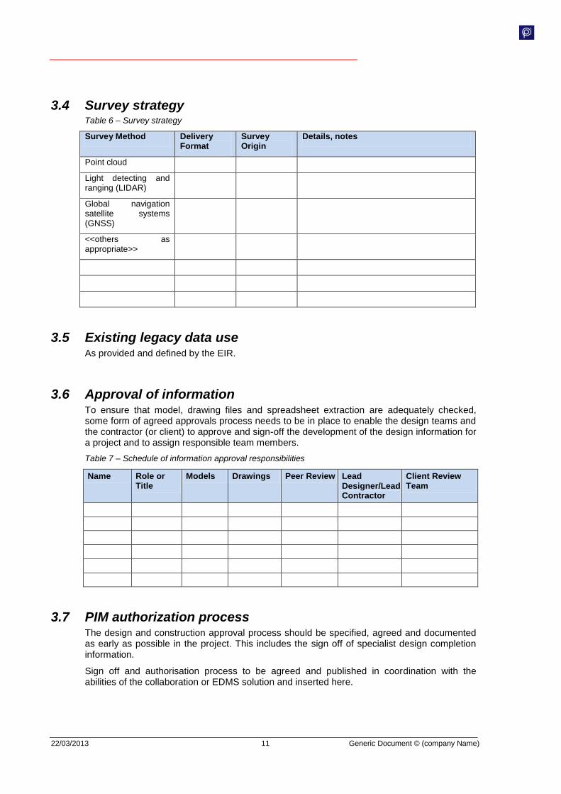
3.4 Survey strategy Table 6 – Survey strategy
Survey Method Delivery Format
Survey Origin
Details, notes
Point cloud
Light detecting and ranging (LIDAR)
Global navigation satellite systems (GNSS)
<<others as appropriate>>
3.5 Existing legacy data use As provided and defined by the EIR.
3.6 Approval of information To ensure that model, drawing files and spreadsheet extraction are adequately checked, some form of agreed approvals process needs to be in place to enable the design teams and the contractor (or client) to approve and sign-off the development of the design information for a project and to assign responsible team members.
Table 7 – Schedule of information approval responsibilities
Name Role or Title
Models Drawings Peer Review Lead Designer/Lead Contractor
Client Review Team
3.7 PIM authorization process The design and construction approval process should be specified, agreed and documented as early as possible in the project. This includes the sign off of specialist design completion information.
Sign off and authorisation process to be agreed and published in coordination with the abilities of the collaboration or EDMS solution and inserted here.

22/03/2013 12 Generic Document © (company Name)
4 Planning and documentation This section of the BEP covers the requirements of PAS1192-2 Clause 7.2.1 b).
4.1 Revised Project Implementation Plan The revised PIP confirms the capability of the supply chain.
The PIP consists of the following completed CPIx documentation:
Supply chain capability summary form, which summarises the contents of …
Supplier building information management assessment form(s)
Supplier IT assessment form(s)
Supplier resource assessment form(s)
These are available as separate templates on the CPIx website.
The supplier resource for the project can also be summarised as per the example in Table 8.
Table 8 – Supplier resource summary
Supplier Discipline Resource numbers
Levels of competence
Years of Experience
Names of individuals
<<name 1>> Qualified Architect
2 RIBA, CAD/BIM, Specification Author
Architectural Technologist (CIAT)
3 CIAT, CAD/BIM Trained
Architectural Technician
5 Certificate of CAD or Model Competence
<<name 2>> Qualified Structural Engineer
3 MIStructE,
Etc
4.2 Agreed project processes for collaboration and information modelling Table 9 – Processes for collaboration and information modelling
Company Solution Network Database File based Comments
22/03/2013 13 Generic Document © (company Name)
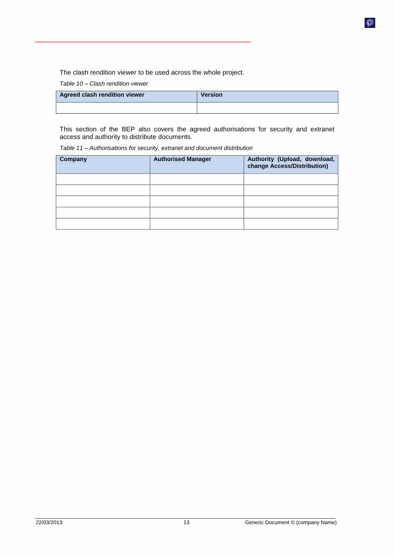
The clash rendition viewer to be used across the whole project.
Table 10 – Clash rendition viewer
Agreed clash rendition viewer Version
This section of the BEP also covers the agreed authorisations for security and extranet access and authority to distribute documents.
Table 11 – Authorisations for security, extranet and document distribution
Company Authorised Manager Authority (Upload, download, change Access/Distribution)
22/03/2013 14 Generic Document © (company Name)
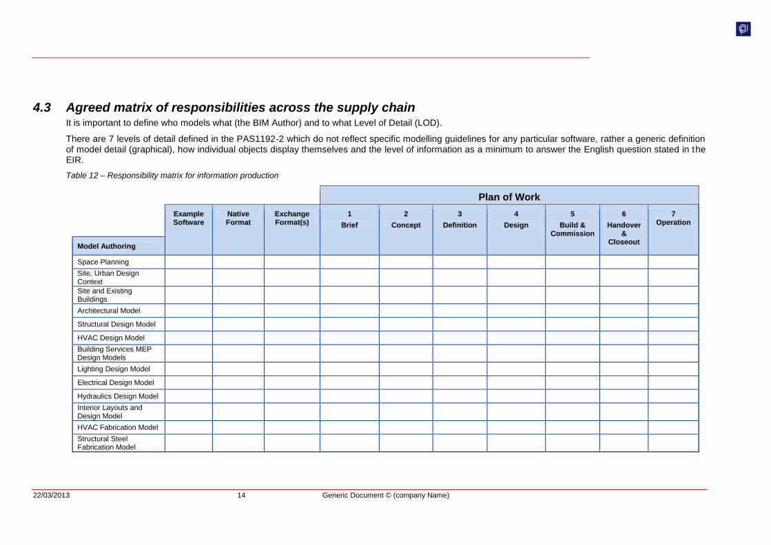
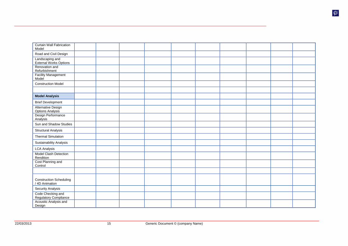
4.3 Agreed matrix of responsibilities across the supply chain It is important to define who models what (the BIM Author) and to what Level of Detail (LOD).
There are 7 levels of detail defined in the PAS1192-2 which do not reflect specific modelling guidelines for any particular software, rather a generic definition of model detail (graphical), how individual objects display themselves and the level of information as a minimum to answer the English question stated in the EIR.
Table 12 – Responsibility matrix for information production
Plan of Work
Example Software
Native Format
Exchange Format(s)
1
Brief
2
Concept
3
Definition
4
Design
5
Build & Commission
6
Handover &
Closeout
7 Operation
Model Authoring
Space Planning
Site, Urban Design Context
Site and Existing Buildings
Architectural Model
Structural Design Model
HVAC Design Model
Building Services MEP Design Models
Lighting Design Model
Electrical Design Model
Hydraulics Design Model
Interior Layouts and Design Model
HVAC Fabrication Model
Structural Steel Fabrication Model
22/03/2013 15 Generic Document © (company Name)
Curtain Wall Fabrication Model
Road and Civil Design
Landscaping and External Works Options
Renovation and Refurbishment
Facility Management Model
Construction Model
Model Analysis
Brief Development
Alternative Design Options Analysis
Design Performance Analysis
Sun and Shadow Studies
Structural Analysis
Thermal Simulation
Sustainability Analysis
LCA Analysis
Model Clash Detection Rendition
Cost Planning and Control
Construction Scheduling / 4D Animation
Security Analysis
Code Checking and Regulatory Compliance
Acoustic Analysis and Design

22/03/2013 16 Generic Document © (company Name)
Disabled Access and Egress
Fire Protection
FM, Operation and Maintenance
Automated/Linked Specifications
Heritage Documentation and Assessment
Solar Envelopes
Overshading
Daylight Analysis
Solar Analysis
Photovoltaic Collectors

22/03/2013 17 Generic Document © (company Name)
4.4 Task information delivery plan (TIDP) A task information delivery plan (TIDP) for each task within the project shall be prepared using the template below so that the format is consistent with the format required for the master information delivery plan. When completed by all team members the TIDPs should be published in this document appendix and on the project extranet.
Table 13 – Template for task information delivery plans
File identifier Model / drawing title
Delivery dates
Project Originator Volume Level File type
Discipline Number Milestone 1
Milestone 2
Milestone 3
Milestone 4
Etc.
4.5 Master information delivery plan (MIDP) The master information delivery plan (MIDP) shall be developed from the separate TIDPs produced for each task within the project. This more detailed, co-ordinated MIDP must be developed and agreed with the stakeholders. When completed the MIDP should be published in this document appendix and on the project extranet as a project plan.

22/03/2013 18 Generic Document © (company Name)
5 Standard method and procedure This section of the BEP covers the requirements of PAS1192-2 Clause 7.2.1 c).
5.1 Volume strategy See Section 5.3 (file naming convention), sub-section Volume for the definitions and abbreviations of volumes to be used on the project.
5.2 PIM origin and orientation The origin and orientation of the project are based on the project location and its reference to other global or local grids, for example Ordnance Survey. Some projects have their own grid system: Crossrail, for instance, uses the London Grid specified for that project, as did the Olympics programme.
See the CPIc Production Information 2003 publication for specific requirements.
Table 14 – Record of information model origin and orientation
Point Grid intersection notation
Easting (m) Northing (m)
Elevation or site Datum
Site local grid origin
Grid origin
Bottom Left Intersection
Grid Intersection Bottom Right
Grid Intersection Top Left
5.3 File naming convention Table 15 – Template for file naming
Project Originator Volume Level or Location
File Type
Discipline Number
See the ‟Guide to BS1192:2007‟ for additional explanation.
Project The „project‟ is an alphanumeric code that is used by the project team to identify the project.
It should not be confused with the Project Contract number which may be different for each company working on the project.
Table 16 – Project code(s)
Code Project
Where an organisation needs to use their own internal project numbers, then they can be indicated in the drawing title block using a separate „project number‟ box.

22/03/2013 19 Generic Document © (company Name)
Originator Table 17 – Originator codes
Code (Abbreviate to
either 2 or three digits) Originator Company name
Volume
Each individual team will provide a copy of their volume strategy in the form of a drawing of each floor layout, section or site with volumes clearly marked named and inserted below. For volumes relating to infrastructure refer to PAS1192-2:2013.
Example:
When planning complex projects and determining the number of model files required, it is
commonplace and good practice for the project to be divided into volumes defined by
coordinates within an overall project model that will be held as separate model files. This
enables multiple users to work on the project efficiently. Volumes should be allocated using
cut lines to indicate their limits. Volume boundaries could be structural joints or grid lines; for
road projects they could be chainage distances; or they could be defined by use e.g. a
vertical distribution shaft.
Each team will provide a copy of their volume strategy in the form of a drawing of each floor
layout with volumes clearly marked and inserted below.
Table 18 – Template for defining project volumes
Discipline/Originator:
Code Volume (Abbreviate to 2 No. alphanumeric characters)

22/03/2013 20 Generic Document © (company Name)
Level or Location
The „level‟ code is a 2 or 3 character alphanumeric code that represents the level or storey of the building. For infrastructure (linear) the level is replaced by location defined as a chainage and offset.
Table 19 – Level or location codes
Code Level Code Location
File type Table 20 – Agreed file types for drawings and models (see BS1192:2007, PAS1192-2)
Code File Type
Table 11 – Agreed file types for documents (see BS1192:2007, PAS1192-2)
Code File Type

22/03/2013 21 Generic Document © (company Name)
Discipline
A list of discipline or role codes as recommended in BS1192 Part 5 are shown in the Table below.
Table 22 – Discipline codes (see BS1192-5)
Code Discipline
A Architect
B Building Surveyor
C Civil Engineer
D Drainage, Highways Engineer
E Electrical Engineer
F Facilities Manager
G Geographical Information System Engineers and Land Surveyor
H Heating and Ventilation Designer
I Interior Designer
K Client
L Landscape Architect
M Mechanical Engineer
P Public Health Engineer
Q Quantity Surveyor
S Structural Engineer
T Town and Country Planner
W Contractor
X Sub-Contractor
Y Specialist Designer
Z General (non-disciplinary)
The „discipline‟ code is a single character indicating the discipline. On larger projects it may be useful to extend the discipline code to 2 characters and listed here.
Table 23 – Extended discipline codes for this project
Code Discipline
Number The „number‟ is a 5-character code. The number may be viewed in a number of ways:
1. Each design disciplines starts at 00001 and then allocates additional numbers to suit their own needs.
2. The first two or three characters of the number could be used to signify an „element code‟ that further classifies the file. One classification code system should be chosen and consistently used by all project teams.

22/03/2013 22 Generic Document © (company Name)
Metadata
Extend the standard Metadata status codes as required for the project, add to but do not change the codes in the PAS1192-2.
Table 24 – Metadata status codes from PAS1192-2
Status Description
Work in Progress
S0 Initial status or WIP Master document index of file identifiers uploaded into the extranet.
Shared (Non-Contractual)
S1 Suitable for Co-ordination The file is available to be „shared‟ and used by other disciplines as a background for their information.
S2 Suitable for Information
S3 Suitable for Internal Review & Comment
S4 Suitable for Construction Approval
S5 Suitable for Manufacture
S6 Suitable for PIM Authorization (Information Exchanges 1-3)
S7 Suitable for AIM Authorization (Information Exchange 6)
D1 Suitable for Costing
D2 Suitable for Tender
D3 Suitable for Contractor Design
D4 Suitable for Manufacture/Procurement
AM As Maintained
Published Documentation (Contractual)
A Suitable for Construction
B
Partially signed-off: For Construction with minor comments from the Client. All minor comments should be indicated by the insertion of a cloud and a statement of “in abeyance” until the comment is resolved, then resubmitted for full authorization.
AB As-Built Handover documentation, PDF, native models, COBie etc.

22/03/2013 23 Generic Document © (company Name)
5.4 Layer naming convention Each discipline should provide the Design Manager and the CAD manager with a full list of all layer names to be used on the project. This list should be published to all members of the project team for information.
Table 25 – Layer naming convention
Field Discipline Classification Presentation Description
Name A - G23 - M2 _ Stairs
Example Architect Stairs (Uniclass) Model graphics (2D)
Some software solutions suggest that layer names are not necessary but it has been found that the convention shall be used when sharing or exchanging information.
5.5 Agreed construction tolerances for all disciplines Table 26 – Agreed tolerances for construction elements according to project discipline
Discipline Element Tolerance
5.6 Drawing sheet templates Table 27 – List of drawing sheet templates
Sheet Size Sheet File name
A0
A1
All drawing template must be rendered and presented at one of a number of approved scales, which are typically defined by the „CAD Manager‟. Scales other than those approved should not be used. The templates shall also be in the standard format for sharing and interoperability.

22/03/2013 24 Generic Document © (company Name)
Table 28 – Drawing sheet scales
Drawing Sheet Scales
All drawings must be rendered and presented at one of a number of approved scales, which are typically defined by the „CAD Manager‟. Scales other than those approved should not be used.
Scale Description of detail
1:1000 1:1000 Scale Detail shows shape and layout
1:500
1:200
1:100 1:100 Scale Detail shows shape, layout and construction elements
1:50 1:50 Scale Detail shows how the construction elements meet at junctions
1:20
1:10
1:5 1:5 Scale detail show shape, dimensions and assembly of the separate
construction elements
1:2 1:2 Scale detail show shape, dimensions and assembly of the separate
construction elements
1:1 All model files must be modelled at 1:1 Scale
5.7 Annotations, dimensions, abbreviations and symbols Each discipline should provide the Design Manager and the CAD manager with a full list to be used on the project. This list should be published to all members of the project team to ensure consistency of the document graphical presentation and shall be consistent throughout the project. Also see BS8541 Parts 1, 2, 3 and 4.
Dimensions should be derived automatically from the underlying CAD coordinates by using the 'associative dimensioning' function of CAD systems. Dimensions should not be entered as 'text' as they are purely graphic characters having no relationship with the underlying CAD coordinates and will cause the relative positions of elements in a drawing to be compromised.
The project team should agree common units of measurement. These should include distance (e.g. metre and millimetre) and angles (e.g. degrees/radians measured clockwise or counter clockwise).
Table 29 – Agreed units of measurement
Type of information
Millimetres Metres Degrees
Radians Clockwise Counter
Survey
Roads
Models
Drawings
5.8 Attribute data Attribute data for the project as defined in the EIR and appropriate COBie templates.

22/03/2013 25 Generic Document © (company Name)
6 IT solutions This section of the BEP covers the requirements of PAS1192-2 Clause 7.2.1 d).
6.1 Software versions The CAD software and versions that will be used by the design teams shall be agreed before starting the project.
Table 30 – Agreed software versions
Company Database CAD software
Version Format Comments
6.2 Exchange formats The agreed formats for model and drawing file exchange are
Table 31 – Agreed exchange formats for models and drawings
DWG DGN DWF PDF IFC Other
Models
Drawings
Final drawing format
Schedules or spreadsheets
6.3 Process and data management systems The process and data management systems shall be described under section 4.2 Agreed project processes for collaboration and information modelling.