post-test examination of a pool boiler receiver
TRANSCRIPT
\
I L
DOE/NASA/33408-6 NASA TM 105635
Post-test Examination of a Pool Boiler Receiver
Robert L. Dreshfield, Thomas J. Moore, and Paul A. Bartolotta National Aeronautics and Space Administration Lewis Research Center
April 1992
Prepared for
U.S. DEPARTMENT OF ENERGY Conservation and Renewable Energy Office of Solar Heat Technologies
l

DISCLAIMER
This report was prepared as an account of work sponsored by an agency of the United States Government. Neither the United States Government nor any agency thereof, nor any of their employees, makes any warranty, express or implied, or assumes any legal liability or responsibility for the accuracy, completeness, or usefulness of any information, apparatus, product, or process disclosed, or represents that its use would not infringe privately owned rights. Reference herein to any specific commercial product, process, or service by trade name, trademark, manufacturer, or otherwise, does not necessarily constitute or imply its endorsement, recommendation, or favoring by the United States Government or any agency thereof. The views and opinions of authors expressed herein do not necessarily state or reflect those of the United States Government or any agency thereof.
Printed in the United States of America
Available from National Technical Information Service U.S. Department of Commerce 5285 Port Royal Road Springfield, VA 22161
NTIS price codes 1 Printed copy: Microfiche copy: A03
1Codes are used for pricing all publications. The code is determined by the number of pages in the publication. Information pertaining to the pricing codes can be found in the current issues of the following publications, which are generally available in most libraries: Energy Research Abstracts (ERA): Government Reports Announcements and Index (GRA and I); Scientific and Technical Abstract Reports (STAR): and publication, NTIS-PR-360 available from NTIS at the above address.
Post-test Examination of a Pool Boiler Receiver
Robert L. Dreshfield, Thomas J. Moore, and Paul A. Bartolotta National Aeronautics and Space Administration Lewis Research Center
April 1992
Work performed by U.S. DEPARTMENT OF ENERGY Conservation and Renewable Energy Office of Solar Heat Technologies Washington, D.C. 20545 Under Interagency Agreement DE-AT04-85AL-33408
DOE/NASA/33408-6 NASA TM 105635
Post-test Examination of a Pool Boiler Receiver
Robert L. Dreshfield, Thomas J. Moore, and Paul A. Bartolotta National Aeronautics and Space Administration Lewis Research Center
April 1992
Work performed by U.S. DEPARTMENT OF ENERGY Conservation and Renewable Energy Office of Solar Heat Technologies Washington, D.C. 20545 Under Interagency Agreement DE-AT04-85AL-33408
DOE/NASA/33408-6 NASA TM 105635

- - - ---- ------ - - ---- -----

POST-TEST EXAMINATION OF A SUB SCALE POOL BOILER TEST APPARATUS
R. Dreshfield, T. Moore, P. Bartolotta National Aeronautics and Space Administration
Lewis Research Center Cleveland, Ohio 44135
SUMMARY
A subscale pool boiler test apparatus to evaluate boiling stability developed a leak after being operated with boiling NaK for 791.4 hr at temperatures from 700 to 750°C. The boiler was constructed using Inconel 625 with a type 304L stainless steel wick for the boiler and type 316 stainless steel for the condenser. The boiler assembly was metallurgically evaluated to determine the cause of the leak and to assess the effects of the NaK on the materials. It was found that the leak was caused by insufficient (about 30 percent) joint penetration in a butt joint. There was no general corrosion of the construction materials, but the room temperature ductility of the Inconel 625 was only about 6.5 percent. A crack in the heat affected zone of the Inconel 625 near the Inconel 625 to type 316 stainless steel butt joint was probably caused by excessive heat input. The crack was observed to have a zone depleted of iron at the crack surface and porosity below that zone. The mechanism of the iron depletion was not conclusively determined.
INTRODUCTION
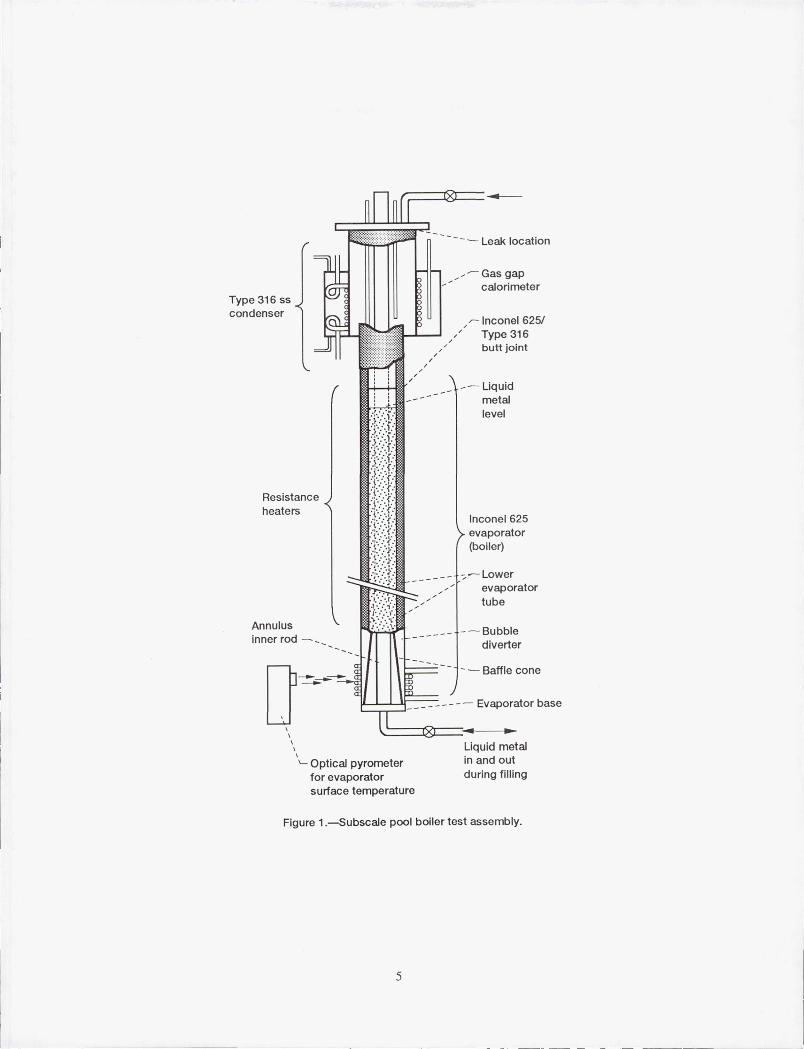
Sandia National Laboratories is evaluating Stirling engines for terrestrial solar applications under the Department of Energy's Solar Thermal Technology Program. The NASA Lewis Research Center is providing management of the Advanced Stirling Conversion System project for the DOE (ref. 1). As part of the project a subscale pool boiler test apparatus was used to evaluate boiling stability of a reflux boiler receiver. The test apparatus was designed and tested by Thermocore, Inc. for Stirling Technology Company under NASA Contract DEN3-377 to provide experimental data on boiling stability for the design of a refluxing pool boiler receiver. The sub scale boiler was operated with eutectic NaK for 791.4 hr at temperatures from 700 to 750°C including 82 cold starts and 60 warm starts (ref. 2). The operation was discontinued when gas was observed in the condenser of the device. After the test apparatus was shut down and the insulation removed, two small leaks were detected by Thermocore personnel in the vicinity of the weld between the condenser and flange at the top of the condenser. The general configuration of the test apparatus and the location of the leaks are shown in figure 1.
The materials used to build the sub scale boiler were type 316 stainless steel for the condenser and Inconel 625 with a type 304L stainless steel wick for the boiler. For most of the life of the test, the heated zone was between 14 and 19 cm above the bottom of the pool boiler. In the early part of the test, the heated zone was between 5 and 10 cm above the bottom of the pool boiler. The overall length of the boiler section was approximately 55 cm.
After the leaks were detected, the subscale pool boiler test apparatus was sent to NASA Lewis for analysis. The boiler was subsequently submitted to the Materials and Structures Divisions for evaluation. This report summarizes that evaluation.
TOP FLANGE/CONDENSER WELD FAILURE
The type 316 stainless steel condenser was cut from the pool boiler just below the flange so that the failure region could be examined. The large stain on the underside of the flange, shown in figure 2, pinpoints the location of the main leak. The weld between the cylindrical condenser and the flange is shown in the
POST-TEST EXAMINATION OF A SUB SCALE POOL BOILER TEST APPARATUS
R. Dreshfield, T. Moore, P. Bartolotta National Aeronautics and Space Administration
Lewis Research Center Cleveland, Ohio 44135
SUMMARY
A subscale pool boiler test apparatus to evaluate boiling stability developed a leak after being operated with boiling NaK for 791.4 hr at temperatures from 700 to 750°C. The boiler was constructed using Inconel 625 with a type 304L stainless steel wick for the boiler and type 316 stainless steel for the condenser. The boiler assembly was metallurgically evaluated to determine the cause of the leak and to assess the effects of the NaK on the materials. It was found that the leak was caused by insufficient (about 30 percent) joint penetration in a butt joint. There was no general corrosion of the construction materials, but the room temperature ductility of the Inconel 625 was only about 6.5 percent. A crack in the heat affected zone of the Inconel 625 near the Inconel 625 to type 316 stainless steel butt joint was probably caused by excessive heat input. The crack was observed to have a zone depleted of iron at the crack surface and porosity below that zone. The mechanism of the iron depletion was not conclusively determined.
INTRODUCTION
Sandia National Laboratories is evaluating Stirling engines for terrestrial solar applications under the Department of Energy's Solar Thermal Technology Program. The NASA Lewis Research Center is providing management of the Advanced Stirling Conversion System project for the DOE (ref. 1). As part of the project a subscale pool boiler test apparatus was used to evaluate boiling stability of a reflux boiler receiver. The test apparatus was designed and tested by Thermocore, Inc. for Stirling Technology Company under NASA Contract DEN3-377 to provide experimental data on boiling stability for the design of a refluxing pool boiler receiver. The sub scale boiler was operated with eutectic NaK for 791.4 hr at temperatures from 700 to 750°C including 82 cold starts and 60 warm starts (ref. 2). The operation was discontinued when gas was observed in the condenser of the device. After the test apparatus was shut down and the insulation removed, two small leaks were detected by Thermocore personnel in the vicinity of the weld between the condenser and flange at the top of the condenser. The general configuration of the test apparatus and the location of the leaks are shown in figure 1.
The materials used to build the sub scale boiler were type 316 stainless steel for the condenser and Inconel 625 with a type 304L stainless steel wick for the boiler. For most of the life of the test, the heated zone was between 14 and 19 cm above the bottom of the pool boiler. In the early part of the test, the heated zone was between 5 and 10 cm above the bottom of the pool boiler. The overall length of the boiler section was approximately 55 cm.
After the leaks were detected, the subscale pool boiler test apparatus was sent to NASA Lewis for analysis. The boiler was subsequently submitted to the Materials and Structures Divisions for evaluation. This report summarizes that evaluation.
TOP FLANGE/CONDENSER WELD FAILURE
The type 316 stainless steel condenser was cut from the pool boiler just below the flange so that the failure region could be examined. The large stain on the underside of the flange, shown in figure 2, pinpoints the location of the main leak. The weld between the cylindrical condenser and the flange is shown in the

longitudinal section in figure 3. Regions of joint separation at the main leak and on the opposite side are indicated. A close up view of the 15 mm long main leak region in figure 4 shows that the leak was located in the weld metal. Cross section A-A from figure 4 is shown in figure 5(a). The joint penetration was only 28 percent. If the penetration had been 100 percent, the weld would have been more than three times as strong and probably would not have failed. A region where a crack in the weld had not extended completely through the wall is shown in figure 5(b). Here, the joint penetration was 38 percent. It is evident that the weld joint failure was a result of inadequate joint penetration (which could have been detected by radiography). The small cross section of the weld simply could not support the deadweight of the structure and the weld failed by creep rupture during the experiment. There was no evidence that corrosion was a factor in this weld joint failure.
DISSIMILAR METAL WELD JOINT
The butt joint, between type 316 stainless steel and Inconel 625 tubing, (fig. 1) was included in this investigation for general information purposes. Both tubes were 76.5 mm diameter with a 1.4 mm wall thickness. A type 304L stainless steel sintered wick was present at the inner surface of the Inconel 625 tubing, just below the weld joint. Unanticipated cracking was discovered in the heat affected zone of the Inconel 625 material at the weld root (fig. 6). This internal cracking was parallel to the weld and did not follow the wick pattern. The photomicrograph in figure 7(a) shows that the cracking proceeded from the inner surface more than halfway through the wall of the Inconel 625 tube. As shown in figure 7(b), both the main crack and a secondary crack were intergranular in nature. As also can be observed in figure 7(b), a thin band of material is present along the walls of the main crack. This band was examined further in a scanning electron microscope. The back-scatter image in figure 8 shows the thin band with porosity under the band. The porosity probably resulted from the Kirkendall effect. Standardless x-ray energy dispersive spectra analysis revealed that the material within the band matched the Inconel 625 base metal spectra except for the absence of Fe. The nominal analysis for Fe in Inconel 625 is 2.5 wt %. No oxygen was detected «5 wt %) within the band which discounts the presence of oxides. This iron depleted region suggests that the NaK may have corroded the Inconel 625 adjacent to the crack (this may be crevice corrosion). However it is also plausible that the Inconel 625 was oxidized when the crack initially formed and the NaK subsequently reduced the oxide layer, preferentially dissolving the iron in the oxide.
Further examination of figure 7(a) shows that the weld width is about 4-1/2 times the thickness of the tubing. In other locations, the weld was as much as 6 times as wide as the tubing. The width of the weld and the concave face are evidence that excessive heat input was used. Thus, overheating during welding rather than a corrosion effect is the most likely cause of the cracking and the cracks probably were present before the boiler was operated. It is likely that radiographic examination would have shown this defect.
OTHER WELD JOINTS
A small microcrack (not shown) was found during metallographic examination of the flange/end plate weld in type 316 stainless steel material. But this flaw did not affect serviceability. The location of the flange/ end plate weld is shown in figure 3.
Metallographic examination of the automatic longitudinal welds in both the Inconel 625 and the type 316 stainless steel tubing revealed that these welds were sound.
2

SUBSCALE BOILER
The subscale boiler section was initially sectioned longitudinally. The interior surface is shown in figure 9. The interior surfaces generally appeared to show little effect of exposure to the NaK. There was a slight discolored region toward the top of the boiler which was a rust color.
The boiler section was cut into 4 sections as shown in figure 10. Sections Band D were about 15 cm long and tensile test samples were prepared from these sections. The tensile test specimens were wire electric discharge machined such that the test section was "dog bone" shaped. The gage length was 25 mm long and 8 mm wide. The grip was about 38 mm long and was flattened for testing. The overall specimen length was about 14 cm. In addition metallographic examination was performed on material taken from sections A, B and D.
Samples of the rust colored deposits were examined by both scanning electron microscopy and x-ray diffraction. Only Fe, Cr, and Ni were detected, the crystal structure being face-centered cubic. That analysis indicates the material is the matrix of the type 304L stainless steel wick material. The colored material is assumed to be too thin to detect by the analytical methods applied.
Metallographic examination of samples from the three different elevations showed no correlation of the microstructure with the elevation of the sample. Representative photomicrographs are shown in figure 11. There is no evidence of NaK attack on either the wick or the substrate. A light etching zone can be seen below the type 304L wick. This is believed to be a nickel rich zone resulting from the wick fabrication process.
The results of room temperature tensile testing of the samples taken from locations Band D are shown in the following table. There are two strength values shown in the form nnnlnnn. The first value is that obtained by using a thickness measured after scraping off loose wick material. The second set of strength values shown are estimates of the Inconel 625 strength after compensating for the type 304L stainless steel wick layer thickness and the thin nickel rich layer under the wick, assuming the steel wick and nickel rich layer carry no load. The latter value was obtained using measurements of the remaining wick with a low power microscope. The actual strength of the Inconel 625 boiler tube is bounded by these values.
RESULTS OF TENSILE TESTS
Sample UTS, 0.2 percent YS, Elongation, MPa MPa percent
B-6 786/910 455/531 6.5
B-7 807/910 -- 6.1
D-4 821/986 -- 7.6
D-6 800/986 462/545 6.0
Typical 825-965 415-620 30-55 Inconel625
The differences among the strength and ductility values for the material tested are believed to be insignificant. The actual strength values compare well with those expected for Inconel 625. The elongation values, however are significantly below those expected for as received Inconel 625. The low elongation value may be either a
3
--- -------
result of the elevated temperature exposure as noted in the literature (ref. 3) or the presence of the wick and the nickel rich layer between the wick and the matrix.
SUMMARY AND CONCLUDING REMARKS
A subscale pool boiler which had been operated about 790 hr between 700 and 750°C with eutectic NaK was examined at NASA Lewis. The following significant observations were made:
1. The leaks observed by Thermocore personnel in the type 316 stainless steel condenser appear to be the result of a welding technique which produced welds with only 28 to 38 percent penetration. It is believed that full penetration welds in the condenser would have survived the test conditions as no corrosion effects were noted in the failed region of the condenser.
2. The Inconel 625 did not appear to be significantly attacked by the NaK exposure, but the room temperanlre ductility of the alloy was significantly reduced (at least four-fold) from normal values for the alloy. It is not known if the reduction in ductility resulted from the thermal exposure, as has been previously observed by others for the alloy, or by the alloy depletion zone associated with the type 304L stainless steel wick. The room temperature strength of the Inconel 625 appeared to be within normal bounds for the alloy.
3. Cracking was observed in the Inconel 625 weld heat affected zone of the weld joining the type 316 stainless steel condenser to the boiler. It is believed that excessive heat input during welding caused the crack which initiated at the internal surface of the pipe.
4. The heat affected zone crack in the Inconel 625 showed evidence of corrosion in that an iron depletion zone and porosity were observed below the surface of the crack. It is not known if the iron in the Inconel 625 was directly attacked by the NaK in the crack, or if the crack had been oxidized when it formed and the iron dissolved when the oxide was subsequently reduced by the NaK. If Inconel 625 is to be considered for NaK service in the future, it is recommended that additional compatibility studies be performed.
5. The room temperature elongation of the Inconel 625 was only 6 to 7 percent after the tests were performed. Typical values for as received material are in excess of 30 percent. While the cause of the ductility degradation was not determined in this investigation, its occurrence suggests that alternative alloys be considered for future hardware in this service.
6. Nondestructive examination of welds by radiographic methods are recommended for future hardware.
REFERENCES
1. Shaltens, R.K.; and Schreiber, J.G.: Status of the Advanced Stirling Conversion System Project for 25 kW Dish Application. Proceedings of the 26th Annual IECEC-Intersociety Energy Conversion and Engineering Conference, D.L. Black, ed., Vol. 5, American Nuclear Society, LaGrange Park, IL, 1991, pp. 388-394.
2. Anderson, W.G., et al.: Alkali Metal Pool Boiling Experiments for a Solar Powered Advanced Stirling Conversion System. To be published in Proceedings of 1992 ASMEfJSES/KSES International Solar Energy Conference, Maui, HI, Apr. 4-8, 1992.
3. Kimball, O.F.; Pieren, W.R.; and Roberts, D.I.: Effects of Elevated-Temperature Aging on the Mechanical Properties and Ductility of Ni-Cr-Mo-Cb Alloy 625. Gulf-GA-AI2683, Gulf General Atomics Company, San Diego, CA., Oct. 1, 1973.
4
-- - - ----- ----------- -
.~-------. . -
r;::::.==:®=== --
Type 316 ss condenser
Resistance heaters
Annulus inner rod ~ _
/
/ /
/
- - - Leak location
/~ Gas gap calorimeter
, --- Inconel 6251 // Type 316
/ / / butt joint
- - Liquid metal level
Inconel 625 evaporator (boiler)
-;.- Lower evaporator tube
-- Bubble diverter
- - - Baffle cone
D~--t=~;::j::-:-::-:-::-:-:-:-=- ---- Evaporator base
\ \ \ \ \
'- Optical pyrometer for evaporator surface temperature
Liquid metal in and out during filling
Figure 1.-Subscale pool boiler test assembly.
5

C-91-04486
Figure 2.-Cross sect ion of 12.7 cm 0.0. condenser showing underside of the flange and a stain at the main leak location. All components are made of Type 316 stainless steel.
C-91-04889
Figure 3.-Cross section at the top of the condenser showing the main leak region and joint separation at the weld between the condenser cylinder and the flange. The material used for all components was Type 316 stainless steel.
6
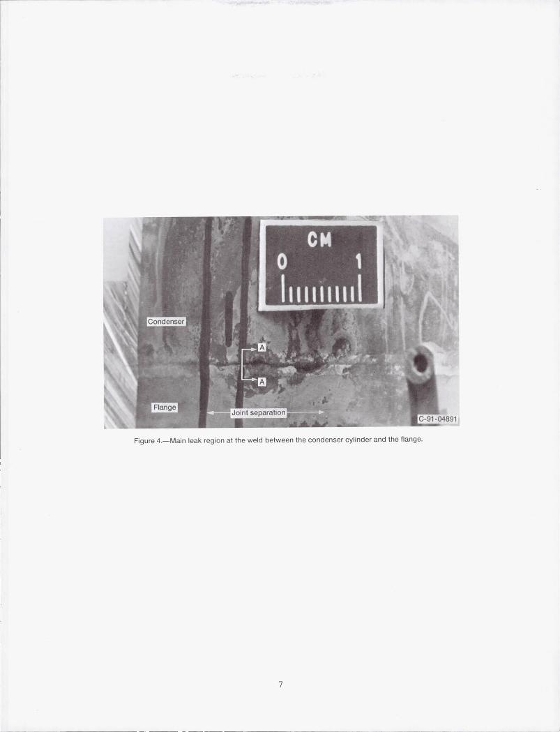
Figure 4.-Main leak region at the weld between the condenser cylinder and the flange.
7
-------- - - -- - - - - - -
Figure 4.-Main leak region at the weld between the condenser cylinder and the flange.
7
-------- - - -- - - - - - -
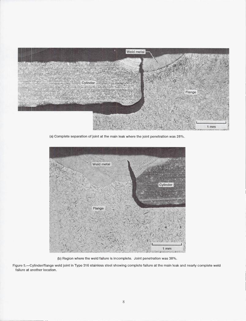
(a) Complete separation of joint at the main leak where the joint penetration was 28%.
(b) Region where the weld failure is incomplete. Joint penetration was 38%.
Figure 5.- Cylinder/flange weld joint in Type 316 stainless steel showing complete failure at the main leak and nearty complete weld failu re at another location.
8

Figure 6.-Weld root (interior) surface of dissimilar metal weld joint between Type 316 stainless steel and Inconel 625 tubing. Cracks are present in the heat affected zone of the Inconel 625 material.
9
Figure 6.-Weld root (interior) surface of dissimilar metal weld joint between Type 316 stainless steel and Inconel 625 tubing. Cracks are present in the heat affected zone of the Inconel 625 material.
9

(a) Cross section of weld joint showing very wide weld and crack in the Inconel 625 heat affected zone.
(b) Main and secondary intergranular cracks in the Inconel 625 base metal.
Figure 7.-Dissimilar metal weld between Type 316 stainless steel and Inconel 625 tubing showing intergranular cracks at the inner surface of the Inconel 625 base metal heat affected zone. 10% chromic acid etch.
10

Top
- ----.~-~
Figure 8.-Backscattered electron image at crack in Inconel 625 base metal. An iron-depleted band is present at the walls of the crack with a porous zone under the band.
Figure 9.-Longitudinal section of boiler showing slight discoloration near top.
II
Bottom
C-91-04503
Top
- ----.~-~
Figure 8.-Backscattered electron image at crack in Inconel 625 base metal. An iron-depleted band is present at the walls of the crack with a porous zone under the band.
Figure 9.-Longitudinal section of boiler showing slight discoloration near top.
II
Bottom
C-91-04503

Calorimeter end (top)
76 mmdiam
1--1- - 51 em ·11 1 0 : C I B : A I
~'5em~ L2~~ Figure 10.-Sub-scale boiler cut-up plan.
Fi ll end (bottom)
(a) Transverse section at top of region A. (b) Transverse section at top of region A showing detail.
......... "" ... .:: ... r--"'!IP.II~IIII , . \. -". ... I ~. ,'"
400~
(c) Transverse section at top of region D. (d) Transverse section at bottom of region B.
Figure 11 .-..'>electec1 photomicrographs of Inconel 625 boiler interface.
12


REPORT DOCUMENTATION PAGE Form Approved
OMB No. 0704-0188 Public reporting burden for this collection of information is estimated to average 1 hour per response, including the time for reviewing instructions, searching existing data sources, gathering and maintaining the data needed, and completing and reviewing the collection of information. Send comments regarding this burden estimate or any other aspect of this collection of information, including suggestions for reducing this burden, to Washington Headquarters Services, Directorate for information Operations and Reports, 1215 Jefferson Davis Highway, SuHe 1204. Arlington, VA 22202-4302, and to the Office of Management and Budget. Paperwork Reduction Project (0704-0188) , Washington, DC 20503.
1. AGENCY USE ONLY (Leave blank) 12. REPORT DATE 1
3.
REPORT TYPE AND DATES COVERED
April 1992 Technical Memorandum 4. TITLE AND SUBTITLE 5. FUNDING NUMBERS
Post-test Examination of a Pool Boiler Receiver
WU-590-13-11 6. AUTHOR(S) DE- AlO4-85-AL33408
Robert L. Dreshfield, Thomas J. Moore, and Paul A. Bartolotta
7. PERFORMING ORGANIZATION NAME(S) AND ADDRESS(ES) 8. PERFORMING ORGANIZATION REPORT NUMBER
National Aeronautics and Space Administration Lewis Research Center E-6978 Cleveland, Ohio 44135-3191
9. SPONSORING/MONITORING AGENCY NAMES(S) AND ADDRESS(ES) 10. SPONSORING/MONITORING AGENCY REPORT NUMBER
National Aeronautics and Space Administration NASA TM-105635
Washington, D.C. 20546-0001 DOE/NASN33408-{)
11. SUPPLEMENTARY NOTES
Responsible person, Robert L. Dreshfield, (216) 433-3267.
128. DISTRIBUTION/AVAILABILITY STATEMENT 12b. DISTRIBUTION CODE
Unclassified - Unlimited Subject Category 26 DOE UC-336
13. ABSTRACT (Maximum 200 words)
A subscale pool boiler test apparatus to evaluate boiling stability developed a leak after being operated with boiling NaK for 791.4 hr at temperatures fro m 700 to 750 °C. The boiler was constructed using Inconel 625 with a type 304L stainless steel wick for the boiler and type 316 stainless steel for the condenser. The boiler assembly was metallurgically evaluated to determine the cause of the leak and to assess the effects of the NaK on the materials. It was found that the leak was caused by insufficient (about 30 percent) joint penetration in a butt joint. There was no general corrosion of the construction materials, but the room temperature ductility of the Inconel 625 was only about 6.5 percent. A crack in the heat affected zone of the Inconel 625 near the Inconel 625 to type 316 stainless steel butt joint was probably caused by excessive heat input. The crack was observed to have a zone depleted of iron at the crack surface and porosity below that zone. The mechanism of the iron depletion was not conclusively determined.
14. SUBJECT TERMS 15. NUMBER OF PAGES
Liquid metals; NaK; Boiler; Inconel 625; Stainless steel; Welding 14
16. PRICE CODE
AD3 17. SECURITY CLASSIFICATION 18. SECURITY CLASSIFICATION 19. SECURITY CLASSIFICA nON 20. LIMITATION OF ABSTRACT
OF REPORT OF THIS PAGE OF ABSTRACT
Unclassified Unclassified Unclassified
NSN 7540-01-280-5500 Standard Form 298 (Rev. 2-89) Prescribed by ANSI Std . Z39-1 B 29B-102

1- ---. --- ----- -- "--l 1- ---. --- ----- -- "--l
National Aeronautics and Space Administration
Lewis Research Center Cleveland, Ohio 44135
Ott\cla. au •• n ... P .... 1ty for Privet. U .. 1300
NI\SI\
FOURTH CLASS MAIL
AbDRESS CORRECTION REQUESTED
111111
Pos.age and Fees Pa,d Na.,ana. Aeronauhcs and Space Admlnlstralton NASA 451
National Aeronautics and Space Administration
Lewis Research Center Cleveland, Ohio 44135
Ott\cla. au •• n ... P .... 1ty for Privet. U .. 1300
NI\SI\
FOURTH CLASS MAIL
AbDRESS CORRECTION REQUESTED
111111
Pos.age and Fees Pa,d Na.,ana. Aeronauhcs and Space Admlnlstralton NASA 451