post treatment system and re-pressurization (loop
TRANSCRIPT
Post Treatment
System
and
Re-Pressurization
(Loop Distribution)
System Operator
Manual
Better Water LLC
Post Treatment System Operation
Post Treatment System Operator Manual
Man Post Treat Operator Rev Mar 2013

Man Post Treat Operator Rev Mar 2013
Our Company…………………………………………… 01 Important Operator Warnings and Cautions…………..... 03 Introduction to the Post treatment System……………… 05 Description…………………..……………………….…. 07 Start Up & Operating Procedures……..………………… 09 Daily Shut Down procedures……………………….…... 13 Post treatment System Monitoring Procedures…...….…. 15 Post Treatment System Adjusting Procedures………..… 17 VFD Operation And Adjustment……………………….. 21 3ft/sec Flow Rates………………………………………. 22 Resistivity Monitor……………………………………… 23 Conductivity Monitor…………………………………… 29 Disinfecting Filters and Dilutions………………………. 31 Post Treatment System Disinfect……………………..… 33 Disinfect and Rinse Operation………………………….. 35 Post Treatment System Troubleshooting..…………...…. 37 System Maintenance……………………………………. 39 Sleeve cleaning & Lamp Replacement…………………. 41 Quality Assurance Checklist……………………………. 43 Summary………............................................................... 45 Warranty……………………………………………....... 47 Appendix 1 Technical Service bulletins……..………… 49 Appendix 2 Post Treatment Test Verification.………… 51
Post Treatment System Operation Table of Contents
Post Treatment System Operator Manual
Man Post Treat Operator Rev Mar 2013

Better WaterBetter WaterBetter WaterBetter Water llc llc llc llc
This Page Left Blank Intentionally
Better Water LLC 698 Swan Drive, Smyrna, TN 37167
Ph. (615) 355-6063, Fax (615) 355-6065
WWW.BETTERWATER.COM
Man Post Treat Operator Rev Mar 2013

Our Company
User Assistance
Information
Contact Us
Better Water LLC 698 Swan Drive Smyrna, TN 37167 Phone 615-355-6063 Fax 615-355-6065
www.betterwater.com
Better Water is a leading integrated manufacturer of water
treatment machines, components and equipment for the
industrial, commercial and institutional markets.
Located in Smyrna, Tennessee,
Better Water continues its history
of manufacturing and worldwide
distribution of equipment
specifically designed for the renal
dialysis market.
Founded in 1971, Better Water
has built a reputation for solving
our customers' toughest problems
with high-quality products and
unmatched service.
Support is available regarding all BW LLC Systems
24 hours-7 Days.
Normal business hours are Monday through Friday (excluding
holidays) 8:00 am to 3:30 pm Central Time call:
615-355-6063 Emergency Assistance is available after normal business hours
(including holidays)
BEFORE calling for emergency assistance:
• Check the Operator’s Trouble-shooting guide
• Check the electrical power connections, fuses and/or
circuit breakers
• Check all valves to ensure each is in the correct position.
If this fails to correct the problem and an emergency
hemodialysis treatment situation exists, call:
615-355-6063 Your call will be automatically forwarded to the on-call cell phone
directory. Please copy all the numbers and select the most
appropriate number for your emergency.
Post Treatment System Operation
Post Treatment System Operator Manual
Man Post Treat Operator Rev Mar 2013
Page 1 of 53

Better WaterBetter WaterBetter WaterBetter Water llc llc llc llc
This Page Left Blank Intentionally
Better Water LLC 698 Swan Drive, Smyrna, TN 37167
Ph. (615) 355-6063, Fax (615) 355-6065
WWW.BETTERWATER.COM
Man Post Treat Operator Rev Mar 2013
Page 2 of 53

Warnings
Better Water llc 698 Swan Drive Smyrna, TN 37167 Phone 615-355-6063 Fax 615-355-6065 www.betterwater.com
Important Operator Warnings
1. It is unsafe to operate or service this device without first
reading and understanding the entire Operator's
Manual. Keep this manual and other associated
documentation for future reference.
2. Misuse, improper operation, and/or improper monitoring
of this system could result in serious injury, death, or
other serious reactions to patients undergoing
hemodialysis treatment.
3. Misuse, improper use or handling of disinfectants and
chemical cleaning solutions could result in serious injury
or even death. You must comply with the information
contained in the Material Safety Data Sheet (MSDS) for
the chemical being used.
4. To avoid electrical shock hazard, do not operate this
device when the covers or panels are removed.
Electromagnetic Interference
This device can create and radiate radio frequency energy and may cause harmful interference if not installed according to the manufacturer’s instructions.
Man Post Treat Operator Rev Mar 2013
Page 3 of 53

Cautions
Better Water llc. 698 Swan Drive Smyrna, TN 37167 Phone 615-355-6063 Fax 615-355-6065
www.betterwater.com
User Cautions
1. When used as a medical device, federal law restricts this
device to sale by or on the authority of a physician. Per
CFR 801.109 (b)(1).
2. Improper operation of this device could result in a low
or no-flow alarm on the dialysis machines.
3. Misuse or improper operation of this device will void any
warranty.
4. Where water is mentioned, unless otherwise noted, it
must be AAMI standard quality water.
5. Electrical and plumbing connections must adhere to
local statutes and any facility codes. Connect this device
to a proper ground connection in accordance with the
National Electrical Code. Do not remove the ground wire
or ground plug. Do not use an extension cord with this
equipment.
6. Do not remove any Caution, Warning or any other
descriptive labels from the device.
7. Do not operate this device in an explosive environment
or in the presence of flammable materials. Do not use
this device to store, mix or transfer flammable liquids.
8. Movement or vibrations during shipment may cause
connections to loosen.
9. Do not operate this unit in an environment where
temperatures may be below 50o F or above 90o F.
10. This device should not be used for purposes outside the device’s stated applications, specifications or limitations.
Man Post Treat Operator Rev Mar 2013
Page 4 of 53
Introduction
Better Water LLC 698 Swan Drive Smyrna, TN 37167 Phone 615-355-6063 Fax 615-355-6065
www.betterwater.com
Your Better Water LLC, Post-Treatment System was designed and built for your water treatment system, and it is of the utmost quality. With proper operation, maintenance and care, this device should give you years of reliable service. Before you start using this device, you must read and understand this manual in its entirety. This manual of Operator's Instructions describes in considerable detail all of the steps and procedures required to safely operate this device. It is unsafe to operate this device without a basic understanding of water treatment and a thorough understanding of the contents of this manual. Your Post-Treatment System was designed and built to your specifications and consideration for the information that has been provided to us on the current product water requirements at your site of operation. Your Post-Treatment System was designed and built to filter product water from the RO or DI product water. This device is not intended for any other application. Once the device has been delivered to you, "it is the responsibility of the Medical Director to ensure that the [device] is operated, monitored, and maintained in such a manner so as to satisfy all applicable standards for which the water may be used". (Quoted from HHS Publication FDA 89-4234). Please keep this manual readily available for each of
your operators to use.
Post Treatment System Operation
Post Treatment System Operator Manual
Man Post Treat Operator Rev Mar 2013
Page 5 of 53
Better WaterBetter WaterBetter WaterBetter Water llc llc llc llc
This Page Left Blank Intentionally
Better Water LLC 698 Swan Drive, Smyrna, TN 37167
Ph. (615) 355-6063, Fax (615) 355-6065
WWW.BETTERWATER.COM
Man Post Treat Operator Rev Mar 2013
Page 6 of 53

Description
Better Water LLC 698 Swan Drive Smyrna, TN 37167 Phone 615-355-6063 Fax 615-355-6065
www.betterwater.com
DESCRIPTION Your Post-Treatment System has up to four Pyrogen Filters that are enclosed in special vessels to process RO Product water or DI water and provide an extremely high recovery rate. This Post-Treatment System is not intended for any other application. The Ultra-filtration process is similar to a Reverse Osmosis Machine. Your Post-Treatment System works from system water pressure boosted with on-board boost pump(s), Units with spiral wound membranes will have a small amount of waste or reject water going to drain. Filter cartridges will not. The output (product) water from the Post-Treatment System is affected by other components in the water treatment system; namely, pressure, temperature and flow-rate. The Pyrogen filters in the Post-Treatment System are of the highest quality known. Pyrogen filters are a consumable product. The life of the filter is directly related to the monitoring and routine care programs you maintain in your facility. A Post-Treatment System, in conjunction with good disinfecting programs, is the most effective means of controlling bacteria and endotoxins in the post treatment and distribution segments of a water purification system. Pyrogen filters can reject bacteria and endotoxins, whereas, submicron filters and ultraviolet irradiators are effective for bacteria alone.
Post Treatment System Operation
Post Treatment System Operator Manual
Man Post Treat Operator Rev Mar 2013
Page 7 of 53

Better WaterBetter WaterBetter WaterBetter Water llc llc llc llc
This Page Left Blank Intentionally
Better Water LLC 698 Swan Drive, Smyrna, TN 37167
Ph. (615) 355-6063, Fax (615) 355-6065
WWW.BETTERWATER.COM
Man Post Treat Operator Rev Mar 2013
Page 8 of 53

Start up & operating
procedures Initial start up
Better Water LLC 698 Swan Drive Smyrna, TN 37167 Phone 615-355-6063 Fax 615-355-6065
www.betterwater.com
START-UP & OPERATING
PROCEDURES 1. Initial/First Time Start-up Procedure:
a) Check to assure that the pump rotation is correct and the voltage is properly balanced. b) Assure the reservoir is full. c) Assure that the loop feed valve is closed and that all water sent to loop will go to drain. d) Open the pump INLET valves. e) Open all by-pass valves (DI by-pass, Post DI by-pass, UF by-pass). f) Close all other valves. g) Place mode switch in MANUAL mode. h) In Manual mode, rotate PUMP SELECTOR switch to #1 or #2 and press PUMP START button. NOTE: Verify pump rotation direction of each pump. i) Pump should start and water should flow through the system and to drain. j) Slowly open DI INLET and OUTLET valves.
Post Treatment System Operation
Post Treatment System Operator Manual
Man Post Treat Operator Rev Mar 2013
Page 9 of 53

Start up & operating procedures
Con’t
Better Water LLC 698 Swan Drive Smyrna, TN 37167 Phone 615-355-6063 Fax 615-355-6065
www.betterwater.com
START-UP & OPERATING
PROCEDURES 1. Initial/First Time Start-up Procedure:
j) Slowly close DI by-pass valve. k) Slowly open post DI 5 micron filter INLET and OUTLET valves. l) Slowly close post DI 5 micron by-pass valve. m) Slowly open Ultra-filter INLET and OUTLET valves. (if applicable) n) Slowly close Ultra-filter by-pass valve. o) Slowly open Ultra-filter reject valve. p) With spiral wound 4x40 membranes, set Ultra-filter reject flow to approximately 5 to 10% of Product flow. There is no reject flow for cartridge based systems. q) At this point the unit should be running through all equipment on the Post Treatment system to drain. r) Let run in this condition for 1 hour in manual mode. s) After 1 hour, rotate PUMP SELECTOR switch to #2 or #1 and press PUMP START button. t) Let run in this condition for 1 hour in manual mode.
u) After the Post-Treatment system has run for at least 2 hours to drain, open appropriate valves and send the water to the loop and return to reservoir. v) Place Post treat system into the AUTO mode and the pump selection switch to the OFF position. Push to restart the Pumps.
Man Post Treat Operator Rev Mar 2013
Page 10 of 53

Start up & operating procedures Con’t
Better Water LLC 698 Swan Drive Smyrna, TN 37167 Phone 615-355-6063 Fax 615-355-6065
www.betterwater.com
2. Daily Start-up Procedure:
a) Insure the Reverse Osmosis Machine has been placed into the Operate Mode, and ensure storage tank is full (not applicable for direct feed systems). b) Open the Post-Treatment System Reject Shut-Off Valve. For 4x40 Pyrogen filter only. No Reject shut off valve is installed with cartridge filters. 3. Auto Mode: (FOR DUAL PUMP UNITS ONLY!)
a) Verify the mode switch is in the AUTO position and press the flashing PUMP START button. The pump scheduled for that day will start. b) The PUMP SELECTOR switch is inactive during AUTO mode but still placed in the OFF position. c) Dual Pumps automatically switch every six hours Pump #1 - 12:00am to 6:00am; Pump #2 – 6:00am to 12:00pm; Pump #1- 12:00pm to 6:00pm; Pump #2 - 6:00pm to 12:00am. (4 cycles per day) d) If there is a problem with either pump while it is running, it will automatically switch to the other pump. If there is still a problem, the pumps will shut down . 4. Manual Mode: (ONLY MODE USED BY SINGLE
PUMP UNITS!)
a) Turn mode switch to MANUAL position. b) Rotate the PUMP SELECTOR switch to the desired pump and press the PUMP START button.
Man Post Treat Operator Rev Mar 2013
Page 11 of 53

Start up & operating procedures Con’t
Auto Reboot
Better Water LLC 698 Swan Drive Smyrna, TN 37167 Phone 615-355-6063 Fax 615-355-6065
www.betterwater.com
5. Auto Reboot:
a) The Auto Reboot will work with either AUTO or MANUAL mode. b) Rotate AUTO REBOOT switch to the “ON” position. i) If Post-Treatment system is NOT running, but in either AUTO or MANUAL mode, the unit will attempt a reboot within 1 minute of turning AUTO REBOOT “ON”. c) In the event of either a power failure, pump and/or flow problem causing the unit to shut down, the Auto-Reboot will attempt to restart unit every hour.
Man Post Treat Operator Rev Mar 2013
Page 12 of 53

Daily shutdown procedures
Better Water LLC 698 Swan Drive Smyrna, TN 37167 Phone 615-355-6063 Fax 615-355-6065
www.betterwater.com
DAILY SHUTDOWN
PROCEDURES With the Reverse Osmosis Machine being placed into a "Flush" or stand-by mode at the end of the hemodialysis day, there is no replacement water being added to your storage tank. 1. Daily Shut-down Procedure:
a) Insure there are no requirements for purified water. b) Close the Post-Treatment system Reject Shut-Off Valve until the flow ceases and the Reject Flow Meter indicates zero flow rate. (This applies to 4x40 spiral wound Ultra-filter Post Treatment Systems only). c) If the Reject flow is not shut off, the Re-pressurization pumps will shut down when the storage tank reaches 20 gallons. This to prevent the pumps from running dry, preventing damage to the pumps.
Post Treatment System Operation
Post Treatment System Operator Manual
Man Post Treat Operator Rev Mar 2013
Page 13 of 53

Better WaterBetter WaterBetter WaterBetter Water llc llc llc llc
This Page Left Blank Intentionally
Better Water LLC 698 Swan Drive, Smyrna, TN 37167
Ph. (615) 355-6063, Fax (615) 355-6065
WWW.BETTERWATER.COM
Man Post Treat Operator Rev Mar 2013
Page 14 of 53
Post Treatment System Monitoring Procedures
Better Water LLC 698 Swan Drive Smyrna, TN 37167 Phone 615-355-6063 Fax 615-355-6065
www.betterwater.com
POST-TREATMENT SYSTEM
MONITORING PROCEDURES 1. Your Post-Treatment System must be monitored on a daily schedule. 2. The Post-Treatment System must be monitored by a Qualified technician using a quality assurance
checklist. An example checklist is provided in the back of this manual. 3. The Post-Treatment System should be checked when there is NO demand for purified water. 4. Monitoring Requirements:
a) Feed (inlet) Pressure b) Product Pressure Refer to Example QA checksheet.
Post Treatment System Operation
Post Treatment System Operator Manual
Man Post Treat Operator Rev Mar 2013
Page 15 of 53

Post Treatment System Monitoring Procedures Con’t
Better Water LLC 698 Swan Drive Smyrna, TN 37167 Phone 615-355-6063 Fax 615-355-6065
www.betterwater.com
4. Monitoring Requirements:
(con’t)
e) Bacteria/Endotoxins (Check at least monthly; more often if necessary) must meet established standards. f) Check Date & Time on Control Module inside control box. If incorrect, see Post-Treatment System Adjusting Procedures. This should be a quarterly check.
Man Post Treat Operator Rev Mar 2013
Page 16 of 53

Post Treatment System Adjusting Procedures
Better Water LLC 698 Swan Drive Smyrna, TN 37167 Phone 615-355-6063 Fax 615-355-6065
www.betterwater.com
POST-TREATMENT SYSTEM
ADJUSTING PROCEDURES 1. On occasion, your Post-Treatment System may require minor adjustments. The adjustments should be made by a qualified technician that is thoroughly familiar with the entire water treatment system. 2. No adjustment to the Post-Treatment System should be made before the upstream equipment and/or systems have been thoroughly checked to insure an upstream component has not caused the out-of-limit readings on the Post-Treatment System. 3. No adjustment to the Post-Treatment System should be made before a thorough quality assurance check of the Post-Treatment System has been completed. 4. Adjustments should be made when there is NO demand for purified water.
NOTE: AAMI states the flow velocity minimum for a Direct Feed Loops is 1.5 ft/s. However, for indirect feed (storage tank fed) systems the recommended flow velocity minimum is 3 ft/s. (See next page for GPM required for 3ft/sec.
Post Treatment System Operation
Post Treatment System Operator Manual
Man Post Treat Operator Rev Mar 2013
Page 17 of 53

Post Treatment System Adjusting Procedures Con’t
Better Water LLC 698 Swan Drive Smyrna, TN 37167 Phone 615-355-6063 Fax 615-355-6065
www.betterwater.com
5. Adjustments:
a) Reject Flow Rate (on 4x40 spiral wound membranes only): i) Locate the Reject Flow Rate adjusting knob on the Post- Treatment System. ii) Slowly turn the knob clockwise or counterclockwise as required to increase or decrease the flow rate to the specified rate found on your Quality Assurance Checklist. b) Setting Date and Time on Control Module i) Relay Controls (1) ‘ESC’ button – escapes current menu screen without saving. (2) ‘OK’ button – saves or confirms changes. (3) or button – scrolls left or right to select item (4) or button – scrolls up or down to select menu item or change digit or code.
Man Post Treat Operator Rev Mar 2013
Page 18 of 53

Post Treatment System Adjusting Procedures Con’t
Better Water LLC 698 Swan Drive Smyrna, TN 37167 Phone 615-355-6063 Fax 615-355-6065
www.betterwater.com
ii) Set Date & Time (1) Press ‘ESC’ until menu shown is displayed: Stop Set Param Set… Prg Name (2) Use or key and scroll down until ‘Set…’ is selected, then press ‘OK’. Go to set clock. (3) Select day of week (Mo-Su) with or key. (4) Scroll right until the first digit of the hours is flashing. Use the or key to set the first digit of the 4 digit time setting. Scroll right to move to the next digit and repeat for each digit until all 4 digits have been set. NOTE: The time is to be set in 24hr format: Midnight = 00:00 Noon = 12:00 1:00am = 01:00 1:00pm = 13:00 2:00am = 02:00 2:00pm = 14:00 3:00am = 03:00 3:00pm = 15:00 4:00am = 04:00 4:00pm = 16:00 5:00am = 05:00 5:00pm = 17:00 6:00am = 06:00 6:00pm = 18:00 7:00am = 07:00 7:00pm = 19:00 8:00am = 08:00 8:00pm = 20:00 9:00am = 09:00 9:00pm = 21:00 10:00am = 10:00 10:00pm = 22:00 11:00am = 11:00 11:00pm = 23:00 (5) Scroll right until the 3rd digit of the year (YYYY) is flashing (the first 2 digits (20) can not be changed). Using the or key, set the 3rd digit. Scroll right and set the 4th digit in the same manner. (6) Scroll right to the first digit (01-12) of the month (MM) and select the 1st digit. Using the or key, set the 1st
digit. Scroll right and set the 2nd digit .
Man Post Treat Operator Rev Mar 2013
Page 19 of 53

Post Treatment System Adjusting Procedures Con’t
Better Water LLC 698 Swan Drive Smyrna, TN 37167 Phone 615-355-6063 Fax 615-355-6065
www.betterwater.com
(7) Scroll right to the first digit (01-31) of the day (DD) and select the 1st digit. Using the or key, set the 1st
digit. Scroll right and set the 2nd digit in the same manner. NOTE: Date format is YY/MM/DD (8) Press ‘OK’ to save changes and exit to menu screen. (9) Press ‘ESC’ to got to main date/time screen.
(10) Go back to set… Scroll down to S/W time… This sets the module to Day Light Savings time. (11) Select S/W time then push OK. Push OK again. Select US2 using the or key then push OK. The display will read > ON OFF S/W Time ON→US2 (12) Push ESC 3 times to return to Time/Date screen.
Man Post Treat Operator Rev Mar 2013
Page 20 of 53

VFD Operation & Adjustment
Better Water LLC 698 Swan Drive Smyrna, TN 37167 Phone 615-355-6063 Fax 615-355-6065
www.betterwater.com
TOSHIBA VFD OPERATION Beginning July 2010 an optional VFD for the Post Treatment Rack and Wall Mount Ultra Filter assemblies is offered by Better Water LLC. The VFD was added for energy savings as well as maintaining proper flow velocities through the RO water loop.
AAMI states the flow velocity minimum for a Direct Feed Loops is 1.5 ft/s. However, for indirect feed (storage tank fed) systems the recommended flow velocity minimum is 3 ft/s. (See next page for GPM required for 3ft/sec.
VFD Control Panel Operation.
The VFD is pre-programmed with operational parameters set by Better Water and locked out to the end user. If trouble shooting VFD issues call Better Water for technical assistance. Located on the VFD front panel are 2 arrow keys, an UP arrow key and a DOWN arrow key. Also located on the Front panel is a display, a RUN and a STOP button (which are inactive during operation) along with the MODE and ENT (ENTER) buttons.
The VFD set point and loop Product flow is set by using the UP or DOWN arrow keys (TOSHIBA model only). To properly set the correct set point for loop flow, push either the UP arrow key or the DOWN arrow key to set desired flow. When desired set point is reached, push the ENT (enter) button. FC will appear in the display. Push either the UP arrow key or DOWN arrow key and verify the set point. Push ENT (enter) button again to complete the operation.
Post Treatment System Operation
Post Treatment System Operator Manual
Man Post Treat Operator Rev Mar 2013
Page 21 of 53

3ft/sec Flow Rates
Better Water LLC 698 Swan Drive Smyrna, TN 37167 Phone 615-355-6063 Fax 615-355-6065
www.betterwater.com
Flow Rate Specs For 3ft Per Second Flow Velocity Loop Pipe Inner Diameter 3/4" Teflon id = 0.60in. 3/4" sch 80 pvc id = 0.74in 1" Teflon id = 0.88in 1" sch 80 id = 0.96in 1 1/2" sch 80 id = 1.48 in 3/4" (25mm) polypropylene id = 0.80in 1" (32mm) polypropylene id = 1.03in 1 1/2" (50mm) polypropylene id = 1.61 in Flow rates @ 3ft/sec 3/4" Teflon = 2.64 gpm @3ft/sec (Nominal) 3/4" sch 80 pvc = 4.02 gpm @3ft/sec (Nominal) 1" Teflon = 5.69 gpm @3ft/sec (Nominal) 1" sch 80 = 6.77 gpm @3ft/sec (Nominal) 1 1/2" sch 80 = 16.1 gpm @3ft/sec (Nominal) 3/4" (25mm) polypropylene = 4.70 gpm @3ft/sec (Nominal) 1" (32mm) polypropylene = 7.79 gpm @3ft/sec (Nominal) 1 1/2" (50mm) polypropylene = 19.0 gpm @ 3ft/sec (Nominal) *All 3ft/sec flow rates at the loop return flow meter are calculated for the loop inner diameter only. The above flow rates should be set with all dialysis machines running. If bicarb or acid makeup water is required both should have the proper flow controls to maintain flow velocity.
Post Treatment System Operation
Post Treatment System Operator Manual
Man Post Treat Operator Rev Mar 2013
Page 22 of 53

Resistivity Monitor
Better Water LLC 698 Swan Drive Smyrna, TN 37167 Phone 615-355-6063 Fax 615-355-6065
www.betterwater.com
Resistivity Monitor For Post Treatment Rack It is recommended the Post Treatment Rack Resistivity Monitor be tested on a quarterly basis (every 3 months) to ensure proper operation in the event the operator has to go onto emergency D.I. Beginning January 2012 the Post Treatment Rack will have divert to drain (DTD) 3 way ball valve built onto the rack. The Resistivity Monitor however will be wall mounted in close proximity to the DTD valve. How To Test The DTD.
1. Plug Resistivity Monitor into a 115 VAC outlet. If testing with RO water the DTD will alarm and the valve will be diverting to drain.
2. Open the Resistivity Monitor control box. Locate the SET/MEASURE/CHECK switch located on Resistivity Monitor. It will be set to MEASURE ( center position). SEE FIG. 1.
3. Push the switch to the right to the CHECK position ( right position). SEE FIG. 2. After 90 seconds the DTD valve will go back to the loop outlet position and the drain will shut off.
4. Push the switch to the far left to the SET position FIG 3 then look at the display FIG 4. NOTE: The DTD valve will open back to drain and the Alarm will resound. It should read 1.2. If adjustment is required below the SET/MEASURE/CHECK to the lower left there are 2 pot screws labeled SET and CHECK. Adjust the SET screw until 1.2 is set in the display. Next check the Resistivity Alarm Box on the patient floor for Poor Quality light and audible piezo alarm.
Post Treatment System Operation
Post Treatment System Operator Manual
Man Post Treat Operator Rev Mar 2013
Page 23 of 53
Resistivity monitor Con’t
Better Water LLC 698 Swan Drive Smyrna, TN 37167 Phone 615-355-6063 Fax 615-355-6065
www.betterwater.com
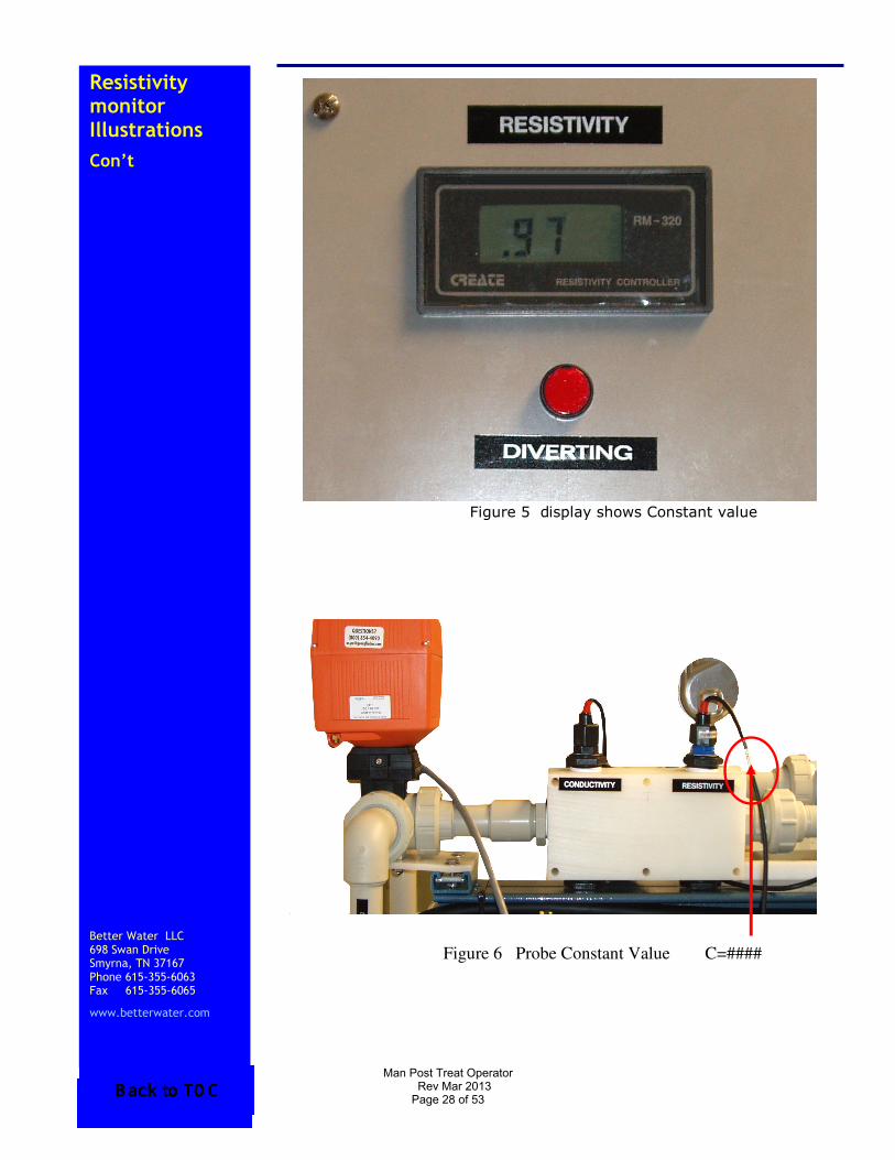
5. Push the switch back to the far right to CHECK again and verify the CONSTANT CHECK value FIG 5. Located on the probe wire next to the probe assembly there is CONSTANT value recorded for the probe FIG 6. An example would be C= 0.970. Look at the display it should read whatever CONSTANT value is recorded on the probe. If the CONSTANT has changed adjust the CHECK set screw until the value matches the probe value.
6. When the CONSTANT value check is completed let the DTD valve go back to the loop outlet position leaving the switch in the CHECK position FIG 2. Verify the DTD valve has gone back to the loop outlet position by looking at the loop return flow meter and for water flow from the loop is returning back to the storage tank. Go to the patient floor and check the Resistivity Alarm Box for a Good Quality light and no piezo alarm. Unplug the Resistivity Monitor. Test is complete.
Man Post Treat Operator Rev Mar 2013
Page 24 of 53

Resistivity Monitor Con’t
Better Water LLC 698 Swan Drive Smyrna, TN 37167 Phone 615-355-6063 Fax 615-355-6065
www.betterwater.com
Testing The Dtd Valve With D. I.
1. Have D.I. tanks online to perform this test. Plug the Resistivity Monitor into a 115 VAC outlet. If poor water quality exist the DTD valve will divert to drain and a alarm will be audible. Located on the bottom Resistivity Monitor is a toggle switch labeled AUTO and TEST. Make sure the toggle switch is set to AUTO.
2. When the water comes to good quality and the rinse up period completes then the DTD valve the will be in the loop outlet position. Verify the DTD valve has gone back to the loop outlet position by looking at the loop return flow meter and water flow from the loop is returning back to the storage tank.
3. Located on the bottom Resistivity Monitor the toggle switch should be set to AUTO. When the water Resistivity is greater the 2 MΩ/cm set the toggle switch to TEST. The DTD valve will go to drain and the alarm will be audible. Go to the patient floor and verify the Resistivity Alarm Box is in Poor Quality and there is a audible piezo alarm audible to the staff.
4. Set the toggle switch back to AUTO. If the Resistivity is still above 2 MΩ/cm the DTD valve will stop diverting to drain after 90 seconds. This is a delayed rinse up period. This time cannot be altered by the end user.
5. The Post Treatment Rack is now ready for D.I. use.
Man Post Treat Operator Rev Mar 2013
Page 25 of 53

Resistivity monitor Illustrations
Better Water LLC 698 Swan Drive Smyrna, TN 37167 Phone 615-355-6063 Fax 615-355-6065
www.betterwater.com
Figure 1 Set to Measure
Figure 2 Set to Check
Man Post Treat Operator Rev Mar 2013
Page 26 of 53

Resistivity monitor Illustrations
Con’t
Better Water LLC 698 Swan Drive Smyrna, TN 37167 Phone 615-355-6063 Fax 615-355-6065
www.betterwater.com
Figure 3 Set to SET
Figure 4 Display shows 1.2
Man Post Treat Operator Rev Mar 2013
Page 27 of 53
Resistivity monitor Illustrations
Con’t
Better Water LLC 698 Swan Drive Smyrna, TN 37167 Phone 615-355-6063 Fax 615-355-6065
www.betterwater.com
Figure 5 display shows Constant value
Figure 6 Probe Constant Value C=####
Man Post Treat Operator Rev Mar 2013
Page 28 of 53

Conductivity Monitor
Better Water LLC 698 Swan Drive Smyrna, TN 37167 Phone 615-355-6063 Fax 615-355-6065
www.betterwater.com
Post Treatment Final Water Quality Conductivity Monitor The Post Treatment Final Water Quality Conductivity Monitor is for monitoring water quality going out to the loop. The Monitor is factory calibrated with a matched probe from the manufacturer. If a replacement is required the old probe cannot be used with a new Monitor. When ordering a Monitor a probe will with the Monitor. Part Number for the Monitor is EQMOBO01305. If the Monitor is replaced follow the set up procedure below. SETUP AND ADJUSTMENTS
1. Upon completion of installation the Monitor has to be setup.
2. Push the SET button. C=1.000 will be in the display. The button scrolls the button changes the number.
3. Look at the probe that comes with Monitor it will tag taped close to the probe. Example: It will read C=0.977. The Monitor says C=1.000 so it has to be changed to our example C=0.977. Push the button to remove the 1. Next push the button to scroll to the next number and change 0 to a 9 with the button. Repeat the same for changing the next two numbers. When finished push SET button to go to the next setting.
Post Treatment System Operation
Post Treatment System Operator Manual
Man Post Treat Operator Rev Mar 2013
Page 29 of 53

Conductivity monitor Con’t
Better Water LLC 698 Swan Drive Smyrna, TN 37167 Phone 615-355-6063 Fax 615-355-6065
www.betterwater.com
4. The next setting is the Alarm Set Point. The display will read 1999 µS/cm. Set this to 1050. Using button to change the number and the button to scroll to the next number. When the set point has been set then push the SET button twice to exit.
5. The display will the conductivity of the water in µS/cm as the default. If ppm is preferred push the button once and display will read in ppm.
The alarm set point is actually 105.0 µS/cm or 50.0ppm not 1050 µS/cm or 500ppm. If a lower set point is desired go to the set point display to change it. Do not change the C=####. Example if the new set point needs to set at 25.0ppm you need to convert ppm to µS/cm. So multiply 25.0 ppm X 2.1 = 52.5 µS/cm. So in the set point display that would be 525 µS/cm = 52.5 µS/cm = 25.0ppm. To convert µS/cm to ppm divide by 2.1. If you want to convert ppm to µS/cm mulitiply by 2.1. The alarm set point will always be in µS/cm not ppm. The Alarm Set-Point of the Final Water quality Monitor should be set to 4x the R.O. Product Water conductivity. On Better Water R.O.s, the conductivity is displayed PPM(TDS). The Final Water Quality Monitor displays in µS/cm2. To convert PPM to µS/cm2: PPM x 2.1 = µS/cm2.
Man Post Treat Operator Rev Mar 2013
Page 30 of 53
Disinfecting
Filters
& Dilutions
Better Water LLC 698 Swan Drive Smyrna, TN 37167 Phone 615-355-6063 Fax 615-355-6065
www.betterwater.com
DISINFECTING THE DISTRIBUTION
SYSTEM AND SPIRAL WOUND
FILTERS/ Absolute Pyrogen Filters
The use of household bleach (5.25%) is common for use in disinfecting water treatment systems and Bicarb delivery systems for hemodialysis. Bleach is a cost effective disinfectant and generally produces satisfactory results. Varying concentrations of Sodium Hypochlorite (bleach) are used among dialysis facilities for disinfection. DILUTIONS:
1. 5.25% household bleach is 50,000 ppm Sodium Hypochlorite
2. 6% household bleach is 60,000 ppm Sodium Hypochlorite
3. 1:1000 Dilution: 5.25%=50 ppm and 6% = 60 ppm. 4. 1:500 Dilution: 5.25%=100 ppm and 6% = 120 ppm. 5. 1:100 Dilution: 5.25%=500 ppm and 6% = 600 ppm. 6. 1:50 Dilution: 5.25%=1000 ppm and 6% = 1200
ppm. 1: 50 Dilution Tank Gallons X 2.56= ounces of bleach 5.25% Tank Gallons X 1.92= ounces of bleach 6%
Post Treatment System Operation
Post Treatment System Operator Manual
Man Post Treat Operator Rev Mar 2013
Page 31 of 53

Disinfecting
Filters
& Dilutions Con’t
Better Water LLC 698 Swan Drive Smyrna, TN 37167 Phone 615-355-6063 Fax 615-355-6065
www.betterwater.com
1:100 Dilution Tank Gallons X 1.28= ounces of bleach 5.25% Tank Gallons X 0.96= ounces of bleach 6% 1:500 Dilution Tank Gallons X 0.64= ounces of bleach 5.25% Tank Gallons X 0.48= ounces of bleach 6% 1:1000 Dilution Tank Gallons X 0.128= ounces of bleach 5.25% Tank Gallons X 0.096= ounces of bleach 6% To convert ounces to milliliters: Fluid Ounces X 29.6= Milliliters Example: 128 oz X 29.6= 3788.8 or 3790 milliliters
Note about Bleach:
Better Water recommends using IRON FREE bleach. Care should be taken to select iron free bleach as many discount or generic bleaches will have high iron content. Iron will be harmful to the equipment and shorten the lifespan. DO NOT use “splash less” bleach. The content of “splash less” bleach will damage the equipment.
Man Post Treat Operator Rev Mar 2013
Page 32 of 53

Post treat system
disinfect
Better Water LLC 698 Swan Drive Smyrna, TN 37167 Phone 615-355-6063 Fax 615-355-6065
www.betterwater.com
POST-TREATMENT SYSTEM
DISINFECTING The Post-Treatment System is disinfected as a component of the Distribution segment of the water treatment system. There are no unique disinfecting requirements for the Post-Treatment System when utilized in this mode of operation. The disinfecting schedule is determined by the Medical Director and the results of bacteria and endotoxins test. Recommended disinfecting solutions for loop/Post-Treatment system: 1. The manual over ride on the divert-to-drain MUST be engaged before disinfecting the water loop 2. A 500 ppm solution of sodium hypochlorite. To make this solution, add 1000 cc’s of 5.25% sodium hypochlorite (household bleach) to 230 gallons of R.O. water in the storage tank. Make sure to the water is flowing through the trapped overflow. * Recommended dwell time: 30-60 minutes. NOTE: The spiral wound ultra-filters are rated at 5000 ppm hour days with proper disinfection. This means that when disinfecting with a 500 ppm Sodium Hypochlorite solution, the ultra-filters would be rated at 240 hours dwell time. As you can see, the ultra-filters have a high tolerance to oxidizers, however, Better Water recommends replacing the 4x40 ultra-filters every 3 years under normal operating conditions. The cartridge based filters should be replaced every 6 months.
Post Treatment System Operation
Post Treatment System Operator Manual
Man Post Treat Operator Rev Mar 2013
Page 33 of 53

Post treat system
disinfect
con’t
Better Water LLC 698 Swan Drive Smyrna, TN 37167 Phone 615-355-6063 Fax 615-355-6065
www.betterwater.com
Post-Treat
System
Disinfect con’t
Better Water LLC 698 Swan Drive Smyrna, TN 37167 Phone 615-355-6063 Fax 615-355-6065
www.betterwater.com
3. A 1% Renalin / Minncare solution (1 quart per 25 gallons of R.O. water) may also be used. The recommended dwell time is 2-4 hours. NOTE: When calculating dosage of disinfectants, one must consider water volumes in the loop piping, cartridge filter housing, 4x40 filter housings, etc. A common practice is to make a larger solution than needed to disinfect and discharge the solution to drain through the loop return-to-drain valve until the proper residual has been obtained, then close the loop return dump valve and let the solution return to the storage tank.
Beginning January 2010 an optional UV light was offered for the Post Treatment systems. When disinfecting the UV light needs to be off or unplugged. Failure to turn off the UV light during disinfection will cause the UV lamp intensity sensor to fail along with damaging the quartz sleeve. When disinfection is completed turn UV light back on.
Man Post Treat Operator Rev Mar 2013
Page 34 of 53

Disinfect and Rinse Operation
Better Water LLC 698 Swan Drive Smyrna, TN 37167 Phone 615-355-6063 Fax 615-355-6065
www.betterwater.com
Disinfect/Rinse Operation: Beginning January 2012 for Disinfecting and Rinsing the Post Treatment Rack the operator will use the OPER/DISINFECT key switch on the front control panel. In this mode the UV and Conductivity Monitor will turn off. The pumps will auto cycle every five minutes so the operator does not have manually cycle the Repressurization pumps during the disinfect and rinsing associated with disinfection. The storage tank now has an inductor for drawing the disinfectant into the storage tank without the operator having to open the lid to pour the disinfectant in. The PRV for the Spray Ball has also been relocated lower so the operator doesn’t have to climb to the top tank for adjustments.
1. Turn the AUTO/MANUAL selector switch to OFF. Make sure the PUMP #1/PUMP #2 selector switch is OFF.
2. Turn the OPER/DISINFECT switch to DISINFECT. PUMP #1 will start first then 5 minutes later PUMP #2 will start and alternate from that point. Check the UV is off and the Conductivity Monitor is off.
3. Prepare the amount of disinfectant to be used. See dilutions. Connect the draw tubing to the quick disconnect of the Inductor but DO NOT place in the disinfectant.
Post Treatment System Operation
Post Treatment System Operator Manual
Man Post Treat Operator Rev Mar 2013
Page 35 of 53
Disinfect and Rinse Operation Con’t
Better Water LLC 698 Swan Drive Smyrna, TN 37167 Phone 615-355-6063 Fax 615-355-6065
www.betterwater.com
4. Now close the Inductor bypass valve to ¾ to fully
closed position. Look at the Loop Return Flow Meter for air bubble if air bubbles are present. If no air bubbles is present close the Inductor Bypass Valve. Then adjust the Spray Ball PRV to 10 to 5 PSI. Bubble should become present. Next slightly crack open the Inductor Bypass Valve but not to much to eliminate the air bubbles. You want to see a steady flow of air bubbles going the Return Flow Meter.
5. Now place draw tubing into disinfectant and verify draw. When disinfectant draw is complete disconnect the draw tube from the Inductor. Next crack the Inductor Ball Valve to ½ to 1/4 open. Next reset the Ball Spray PRV to 20 to 25 PSI.
6. Proceed with disinfection rinsing. 7. When disinfection and rinsing is complete turn the
OPER/DISINFECT key switch back to OPER. Select AUTO on the AUTO/MANUAL selector switch. The Repressurization pump will restart, the UV will come on, and the Conductivity Monitor will power back up.
8. When AUTO is selected the pumps will cycle every 6 hours. The time cycles for each pup is as follows:
12:00am to 6:00am PUMP #1 6:00am to 12:00pm PUMP #2 12:00pm to 6:00pm PUMP #1 6:00pm to 12:00am PUMP #2
Man Post Treat Operator Rev Mar 2013
Page 36 of 53
Post treat system
Trouble shooting
Better Water LLC 698 Swan Drive Smyrna, TN 37167 Phone 615-355-6063 Fax 615-355-6065
www.betterwater.com
POST-TREATMENT SYSTEM
TROUBLE-SHOOTING GUIDE
TROUBLE SHOOTING GUIDE WITH USER
CORRECTIVE ACTION:
PROBLEM: The recovery rate is <90%: CORRECTIVE ACTION:
1. Adjust the Waste (reject) Control Valve to establish a recovery rate of 90-95%. If this does not correct the problem, call for technical support. PROBLEM: The product (permeate) flow has decreased by 10% or greater. CORRECTIVE ACTION:
1. Check the pump outlet pressure from the re-pressurization pump, if the pump pressure has decreased below design specification, consult pump trouble- shooting guide. 2. Check the temperature gauge (post Blending Valve). If <70F, adjust the Blending Valve to increase the temperature to >70F. 3. Disinfect.
Post Treatment System Operation
Post Treatment System Operator Manual
Man Post Treat Operator Rev Mar 2013
Page 37 of 53
Post treat system
Trouble shooting
Con’t
Better Water LLC 698 Swan Drive Smyrna, TN 37167 Phone 615-355-6063 Fax 615-355-6065
www.betterwater.com
PROBLEM: The product (permeate) water is contaminated with microbiological contaminants (bacteria and/or endotoxins).
CORRECTIVE ACTION:
1. Disinfect. 2. If disinfection does not correct the problem, call for technical assistance; the ultra-filter(s) must be replaced. PROBLEM: The pressure drop is >15 psi per ultra-filter (three ultra-filters should not exceed a total of 30 psi pressure drop). CORRECTIVE ACTION:
1. Disinfect. 2. Remove and replace the ultra-filters.
Man Post Treat Operator Rev Mar 2013
Page 38 of 53

SYSTEM
MAINTENANCE
MAINTENANCE
SCHEDULE
Better Water llc . 698 Swan Drive Smyrna, TN 37167 Phone 615-355-6063 Fax 615-355-6065
www.betterwater.com
Maintenance Task Frequency (More Often If Needed)
Notes
Check the Post Treatment For Leaks
Daily Visual Inspection
Monitor the Post Treatment For Unusual Sounds
Daily Visual/Auditory
Clean External Surfaces
Weekly Use Soft Damp Towel
or Sponge. (DO NOT USE BLEACH)
Record Operational Values (i.e. Flows, Pressures, Temperature, etc
Daily or more often as required by facility
Record on Daily (Shift) Checklist
Change Pyrogen Absolute Filter
Every 6 months Call Better Water for P/N
Change 4x40 spiral wound Pyrogen Filters
Every 3 years Call Better Water for P/N
UV Lamp Every 12 Months Call Better Water for P/N
UV quartz sleeve Every 12 Months Call Better Water for P/N
Post-treatment System Maintenance
Post Treatment System Operator Manual
Man Post Treat Operator Rev Mar 2013
Page 39 of 53

Better WaterBetter WaterBetter WaterBetter Water llc llc llc llc
This Page Left Blank Intentionally
Better Water LLC 698 Swan Drive, Smyrna, TN 37167
Ph. (615) 355-6063, Fax (615) 355-6065
WWW.BETTERWATER.COM
Man Post Treat Operator Rev Mar 2013
Page 40 of 53
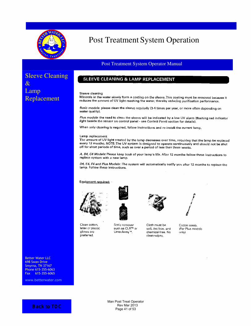
Sleeve Cleaning & Lamp Replacement
Better Water LLC 698 Swan Drive Smyrna, TN 37167 Phone 615-355-6063 Fax 615-355-6065
www.betterwater.com
Post Treatment System Operation
Post Treatment System Operator Manual
Man Post Treat Operator Rev Mar 2013
Page 41 of 53

Better WaterBetter WaterBetter WaterBetter Water llc llc llc llc
This Page Left Blank Intentionally
Better Water LLC 698 Swan Drive, Smyrna, TN 37167
Ph. (615) 355-6063, Fax (615) 355-6065
WWW.BETTERWATER.COM
Man Post Treat Operator Rev Mar 2013
Page 42 of 53

Example of A WATER TREATMENT SYSTEM QUALITY ASSURANCE CHECKLIST
ITEM(S TO BE CHECKED) MON
TUE
WED
THU
FRI
SAT
SUN
DATE
STORAGE TANK:
WATER LEVEL ABOVE 2nd FLOAT
.2 VENT FILTER
LAST CHANGED
NEXT CHANGE DUE
PSI POST-REPRESS. PUMP
D.I. TANKS
PSI PRE-D.I
PSI POST-D.I.
D.I. TANK(S) ∆P (<15)
POST-D.I. 5 MICRON
PSI PRE-5 MICRON FILTER (IF USED)
PSI POST-5 MICRON FILTER (IF USED)
POST-D.I. 5 MICRON ∆P (<15)
U.V. LIGHT (IF USED)
PSI PRE-U.V.
PSI POST-U.V.
LIGHT ON ?
CARTRIDGE BASED PYROGEN FILTER
(IF USED)
PSI PRE-20 INCH FILTER (IF USED)
PSI POST-20 INCH FILTER (IF USED)
.03 ABSOLUTE FILTER ∆P (<15)
4x40 SPIRAL WOUND ULTRA FILTER
(POST-TREAT)
PSI PRE 4 X 40 (IF USED)
PSI POST 4 X 40 (IF USED)
PRODUCT FLOW IN GPM
REJECT FLOW IN GPM
LOOP RETURN FLOW IN GPM (IF USED)
LOOP RETURN PRESSURE
(PRESS. BY-PASS)
4x40 SPIRAL WOUND ULTRA FILTER
(REUSE)
PSI PRE 4 X 40 (IF USED)
PSI POST 4 X 40 (IF USED)
PRODUCT FLOW IN GPM
REJECT FLOW IN GPM
LOOP RETURN FLOW IN GPM (IF USED)
LOOP RETURN PRESSURE(PRESS. BY-PASS)
TECHNICIAN’S INITIALS
Man Post Treat Operator Rev Mar 2013
Page 43 of 53

Better WaterBetter WaterBetter WaterBetter Water llc llc llc llc
This Page Left Blank Intentionally
Better Water LLC 698 Swan Drive, Smyrna, TN 37167
Ph. (615) 355-6063, Fax (615) 355-6065
WWW.BETTERWATER.COM
Man Post Treat Operator Rev Mar 2013
Page 44 of 53
Summary
Better Water LLC 698 Swan Drive Smyrna, TN 37167 Phone 615-355-6063 Fax 615-355-6065
www.betterwater.com
SUMMARY Daily Start-up Procedure:
Open the Reject Flow Shut-Off Valve. Daily Monitoring Requirements are found on your
Quality Assurance Checklist.
1. Pressure Drop. 2. Permeate Pressure. 3. Permeate Flow-rate. 4. Reject Flow-rate. 5. Recovery Rate. Post-Treatment System Disinfection Procedures:
The Post-Treatment System is included in the Distribution Segment disinfection program; therefore, there are no special or extra procedures required. Daily Shut-down Procedures:
1. Insure there are no requirements for purified water. 2. Close the Reject Flow Shut-Off Valve until the Reject Flow ceases and reads "0" on the Reject Flow Meter.
Post Treatment System Operation
Post Treatment System Operator Manual
Man Post Treat Operator Rev Mar 2013
Page 45 of 53

Better WaterBetter WaterBetter WaterBetter Water llc llc llc llc
This Page Left Blank Intentionally
Better Water LLC 698 Swan Drive, Smyrna, TN 37167
Ph. (615) 355-6063, Fax (615) 355-6065
WWW.BETTERWATER.COM
Man Post Treat Operator Rev Mar 2013
Page 46 of 53

Limited Warranty
Better Water LLC 698 Swan Drive Smyrna, TN 37167 Phone 615-355-6063 Fax 615-355-6065
LIMITED WARRANTY TERMS and CONDITIONS a. This limited warranty is given only to the original buyer and covers the equipment delivered with this limited warranty. b. The buyer shall be barred from any recovery on this limited warranty or otherwise for damages due in whole or in part to… … unreasonable use … improper operation … use beyond normal fashion … failure to follow instructions … failure to maintain the product in good condition and repair … or the like. c. If the buyer discovers or should have discovered a defect in which it is reasonable to conclude that damage, either personal, property, or economic, may result, the buyer's continued use of the product shall constitute any assumption of risk by the buyer and a bar to any recovery for breach of this limited warranty or otherwise. d. No oral or written representation, information, or advice given by Better Water LLC or any of its representatives shall create a warranty or in any way increase the scope of this express limited warranty and shall not form a part of the basis for bargain.
WHAT IS WARRANTED AND FOR HOW LONG? a. All equipment, excluding ion exchange and filtration media and cartridges, are warranted to be free from factory defects in materials, and workmanship under normal use for a period of one (1) year from the date of shipment. b. It is a condition precedent to recovery on this limited warranty that the buyer strictly comply with all operating and maintenance guidelines established by Better Water LLC and that the serial number (if applicable) is intact and legible on the equipment. c. It is a condition precedent to recovery on this limited warranty for damage to the external finish of the equipment that the buyer notifies Better Water LLC at the time of the installation that the finish is damaged.
WHAT IS REMEDY FOR BREACH OF THIS LIMITED WARRANTY or NEGLIGENCE BY BETTER WATER LLC a. Buyer's sole and exclusive remedy for any breach of this limited warranty or negligence by Better Water LLC shall be repair or replacement of the defective part, at the option of Better Water LLC, provided such defective part is returned to Better Water LLC for inspection. b. Better Water LLC shall not be obligated to supply an exact replacement of the defective part and reserves the right to substitute new and improved parts.
Post Treatment System Operation
Post Treatment System Operator Manual
Man Post Treat Operator Rev Mar 2013
Page 47 of 53

Limited
Warranty Con’t
Better Water LLC 698 Swan Drive Smyrna, TN 37167 Phone 615-355-6063
Limited
Warranty Con’t
Better Water LLC 698 Swan Drive Smyrna, TN 37167 Phone 615-355-6063 Fax 615-355-6065
www.betterwater.com
c. Better Water LLC shall provide at no cost to buyer, labor to remove and/or replace defective parts covered by this limited warranty for a period of ninety (90) days from the date of installation by Better Water LLC of the equipment. d. After such ninety (90) day period, buyer shall be responsible for any labor or service charge for the removal and/or replacement of any defective parts. e. Buyer shall be responsible for all travel expenses and freight charges at all times. f. Better Water LLC shall have no obligation to repair or replace any defective part if buyer fails to follow the procedure set forth in “HOW TO OBTAIN A REPLACEMENT PART UNDER LIMITED WARRANTY”. IN NO EVENT SHALL THIS LIMITED WARRANTY BE CONSTRUED TO COVER, NOR SHALL BETTER WATER LLC BE LIABLE TO BUYER AS ANY OTHER PERSON FOR, ANY CONSEQUENTIAL, INCEDENTAL, ECONOMIC, DIRECT, INDIRECT, GENERAL OR SPECIAL DAMAGES, WHICH ARE HEREBY EXPRESSLY DISCLAIMED. HOW TO OBTAIN A REPLACEMENT PART UNDER LIMITED WARRANTY a. Buyer should contact the Customer Service or Technical Support Departments and request a Return Goods Authorization. b. Described part(s) will be sent with a purchase order. c. The returned part(s) will be returned to the factory for limited warranty consideration. If part(s) are not covered under the limited warranty, part(s) will be considered billable against the purchase order supplied. WHAT IS NOT COVERED BY THIS LIMITED WARRANTY: By way of example and not limitation, this limited warranty does not cover:
• Damage to or replacement of any ion exchange resin of filter media • Labor or service charges for the removal and/or replacement of any
defective parts after the ninety (90) day period from the date of installation or sale by Better Water LLC
• Freight charges and travel expenses • Damage from inadequate or defective wiring, improper voltage,
improper connections or electrical service, inadequate or defective plumbing, water supply, or water pressure, or in violation of applicable building, plumbing or electrical codes, laws, ordinances or regulations.
• Damage from improper installation or operation, including but not limited to, abuse, accident, neglect, improper maintenance, freezing and fires, or abnormal use.
• Damage caused by contaminants in Buyer’s water supply, including hardness, chlorine, chloramines, sulfur, bacterial iron, tannin, algae, oil, organic matter or other unusual substances, if special equipment has not been installed by Better Water LLC to remove such contaminants
• Damage to or caused by filters/membranes or other replacement parts not purchased from Better Water LLC or damage caused by modification, alteration, repair or service of the equipment or any of its parts by anyone other than Better Water LLC or its expressly authorized representatives.
Man Post Treat Operator Rev Mar 2013
Page 48 of 53
Better WaterBetter WaterBetter WaterBetter Water llc llc llc llc
Appendix 1
Post Treatment Technical
Service Bulletins
Better Water LLC 698 Swan Drive, Smyrna, TN 37167
Ph. (615) 355-6063, Fax (615) 355-6065
WWW.BETTERWATER.COM
Man Post Treat Operator Rev Mar 2013
Page 49 of 53

Better WaterBetter WaterBetter WaterBetter Water llc llc llc llc
This Page Left Blank Intentionally
Better Water LLC 698 Swan Drive, Smyrna, TN 37167
Ph. (615) 355-6063, Fax (615) 355-6065
WWW.BETTERWATER.COM
Man Post Treat Operator Rev Mar 2013
Page 50 of 53

Relocation of Wire on Replacement VFDs TSB 2012010
Created/Last Revised Date 11/09/2012
Last Reviewed Date 11/09/2012
Page 1 of 1
OVERVIEW: The manufacturer discontinued the model of the VFD used in Better Water LLC’s 3046 ROs and Post-treatment devices in October of 2012. The replacement model is functionally the same with the exception of the use of one of the terminal posts and the location of grounding posts, both requiring the relocation of wires if the old model VFD is replaced with the new model. Better Water LLC’s part number of EQMOBO01350 which is the “3 Phase-In / 3 Phase-Out / 5 Horsepower VFD“ will remain the same. The difference between these two models is mostly cosmetic. See the pictures below of the old and new models.
TERMINAL POST & GROUND WIRE RELOCATION: 1. Turn off the power, and unplug the device from the electrical outlet before opening the control box. 2. On the old model VFD, take note of the location of the wire (from the pressure transducer) on the terminal
post labeled VIA and where the three ground wires are located. 3. Replace the old model VFD with the new model VFD, reconnecting the wires with the following exceptions.
4. On the new model VFD, relocate the wire (from the pressure transducer) to the terminal post labeled VIC. 5. Relocate the three ground wires to the three grounding posts on the bottom of the new model VFD.
TECHNICAL SERVICE BULLETIN
Old Model VFD White/Cream color with hinged cover
Front View
New Model VFD Black color, no hinged cover
Front View
Old Model VFD Wire located on terminal post VIA
New Model VFD Wire located on terminal post VIC
Old Model VFD Three ground wires
New Model VFD Three grounding posts
Man Post Treat Operator Rev Mar 2013
Page 51 of 53

Better WaterBetter WaterBetter WaterBetter Water llc llc llc llc
This Page Left Blank Intentionally
Better Water LLC 698 Swan Drive, Smyrna, TN 37167
Ph. (615) 355-6063, Fax (615) 355-6065
WWW.BETTERWATER.COM
Man Post Treat Operator Rev Mar 2013
Page 52 of 53

Better WaterBetter WaterBetter WaterBetter Water llc llc llc llc
Appendix 2
Post Treatment TEST
VERIFICATION
AND RESULTS
Better Water LLC 698 Swan Drive, Smyrna, TN 37167
Ph. (615) 355-6063, Fax (615) 355-6065
Man Post Treat Operator Rev Mar 2013
Page 53 of 53