potential bone replacement materials prepared by two … · prior to infiltration, ... figure 2...
TRANSCRIPT

Potential Bone Replacement Materials Prepared by Two Methods
Steve Lee1, Michael Porter1, Scott Wasko2, Grace Lau3, Po-Yu Chen4, Ekaterina E. Novitskaya1, Antoni P. Tomsia3, Adah Almutairi2, Marc A. Meyers1,5 and Joanna McKittrick1,5
1 University of California, San Diego, Materials Science and Engineering Program, 9500 Gilman Dr., La Jolla, CA 92093 USA 2 University of California, San Diego, Skaggs School of Pharmacy, 9500 Gilman Dr., La Jolla, CA 92093 USA 3Lawrence Berkeley National Laboratory, 1 Cyclotron Rd., Berkeley, CA 94720 USA 4 National Tsing Hua University, Department of Materials Science and Engineering, Hsinchu 30013, Taiwan, R.O.C. 5University of California, San Diego, Dept. of Mechanical and Aerospace Engineering, 9500 Gilman Dr., La Jolla, CA 92093 USA ABSTRACT
Natural and synthetic hydroxyapatite (HA) scaffolds for potential load-bearing bone
implants were fabricated by two methods. The natural scaffolds were formed by heating bovine cancellous bone at 1325°C, which removed the organic and sintered the HA. The synthetic scaffolds were prepared by freeze-casting HA powders, using different solid loadings (20–35 vol.%) and cooling rates (1–10°C/min). Both types of scaffolds were infiltrated with polymethylmethacrylate (PMMA). The porosity, pore size, and compressive mechanical properties of the natural and synthetic scaffolds were investigated and compared to that of natural cortical and cancellous bone. Prior to infiltration, the sintered cancellous scaffolds exhibited pore sizes of 100 – 300 µm, a strength of 0.4 – 9.7 MPa, and a Young’s modulus of 0.1 – 1.2 GPa. The freeze-casted scaffolds had pore sizes of 10 – 50 µm, strengths of 0.7 – 95.1 MPa, and Young’s moduli of 0.1 –19.2 GPa. When infiltrated with PMMA, the cancellous bone-PMMA composite showed a strength of 55 MPa and a Young’s modulus of 4.5 GPa. Preliminary data for the synthetic HA-PMMA composite showed a strength of 42 MPa and a modulus of 0.8 GPa.
INTRODUCTION
Understanding the structure and mechanical properties of natural bone is vital for developing new bioinspired bone implants. Bone has a complex hierarchical structure from the nano- to macro-scale. Composed of two main types of osseous tissue, cortical and cancellous, bone is a composite material consisting of ~ 67 wt% carbonated apatite minerals, also known as hydroxyapatite (HA), embedded within an organic matrix of type I collagen [1]. Figure 1 illustrates the structural hierarchy of cortical and cancellous bone. Cortical bone is a dense (~ 2.0 g/cm3) collection of cylindrical lamellar sheets composed of aligned, mineralized collagen fibers (osteons) surrounding vascular channels (Haversian canals) necessary for blood flow. Cancellous bone, on the other hand, is a highly porous open cell, foam-like material with high surface area and low density (0.2 – 0.5 g/cm3) composed of lamellar sheets of mineralized collagen fibers. Unlike cortical bone, cancellous bone contains flat lamellae rather than cylindrical osteons [2].

The porosity and pore size of cancellous bone is much greater than that of cortical bone: cancellous bone has 75 – 85 % porosity with 300-600 µm diameter pores and cortical bone has 5 – 10 % porosity with 10 – 50 µm diameter pores. In its natural hydrated state, cortical bone has a compressive strength (σ) of 110 – 150 MPa, and Young’s modulus (E) of 18 – 22 GPa [3], while cancellous bone has a compressive strength and Young’s modulus of 2 – 6 MPa and 0.1 – 0.3 GPa, respectively [4].
Figure 1. Structural hierarchy of cortical and cancellous bone.
Bone is a uniquely complex composite relying on the interplay of each hierarchical level to achieve its strength, toughness and low density. When synthesizing bioinspired materials for use as a bone implant/substitute, these and several other important factors must be taken into consideration:
Biocompatibility Biodegradability/resorbability Osteoconductivity Osteoinductivity Interconnected porosity Proper stiffness and strength
All biomaterials must be biocompatible to avoid a chronic immune response by the host. In some cases biodegradability or bioresorbability is desirable so that natural tissues eventually grow into and replace the implant, restoring full function back to the host. The materials for bone implants should be osteoconductive, such that mesenchymal stem cells and osteoblasts are attracted to the implant. The surface should also be osteoinductive, allowing for the formation of new osteoblasts and adequate bone ingrowth. Beyond biocompatibility, the mechanical stresses experienced by bone can greatly affect osteogenesis - the natural synthesis of new bone tissue by osteoblasts. A stiffness mismatch between the implant and bone, where the implant has a much higher stiffness, may cause a reduction in bone mass surrounding the implant over time. This phenomenon, known as stress shielding, is a result of the growth and remodeling of bone in response to external loading.
Porosity is closely related to the mechanical properties of bone implant materials. Implant porosity has a direct effect on osteogenesis and integration with natural bone [5,6]. The pores

must be interconnected with an interconnection size of at least 50 µm which is needed to promote bone ingrowth [7]. Hulbert et al. determined that a minimum pore size of at least 100 µm was required for significant ingrowth of bone into an implant [8]. More recent studies by Chang et al., however, have shown that ingrowth is possible with pore sizes down to 50 µm [9].
Scaffolds with high porosity and desirable mechanical properties for bone implants have been developed by many research groups with varying success [10-15]. One new method developed to produce highly oriented, microstructures with varying porosity is freeze-casting. Freeze-casting is a physical process in which an aqueous slurry, typically composed of a solid phase (i.e. ceramic powder) and a fugitive liquid carrier (e.g. water), is directionally frozen in a mold, then sublimated to remove the frozen liquid phase and sintered to densify the porous ceramics [16]. Several research groups have developed varying techniques for freeze-casting biocompatible ceramics, such as HA, for potential tissue engineering applications [17-29].
Freeze casting is an elegant process for developing bone scaffolds. Physical and mechanical properties are easily controlled by simple modification to slurry formulations or cooling rates. During solidification, particle trapping is required to produce desired microstructures. Particle trapping depends on two main parameters: the free energy of the system and velocity of the freezing front. First, the free energy of the system (Δσ0) must be negative
∆휎 = 휎 − 휎 + 휎 < 0, (1)
where 휎 , 휎 and 휎 are the surface energies between particle and solid, particle and liquid, and solid and liquid, respectively [30]. Second, the velocity of the freezing front (ν) must be greater than the critical velocity (νcr) determined by a balance of the attractive force (퐹 ) and repulsive force (퐹 ) acting on the particle
Fh =
6phnr 2
d (2)
FR = 2p rDs o
ao
dæ
èçö
ø÷ (3)
ncr =
Ds oao
3hr (4)
where η is the dynamic viscosity of the liquid, r is the radius of the particle, a0 is distance between the molecules in the liquid layer, and d is the thickness of the liquid layer between the particle and the solid-liquid interface [30]. If the velocity of the freezing front is lower than νcr, particles will be rejected and pushed above the solidification plane; if the velocity is faster, particle trapping will occur. Figure 2 shows a graphical representation a particle near the liquid-solid interface during freeze-casting [30].

Figure 2. Schematic of particle–freezing-front interactions. A particle of radius r separated from the solid–liquid interface by a liquid film of thickness d experiences an attractive force Fη and a repulsive force FR. Balancing the forces, a critical freezing-front velocity v can be calculated, above which the particle will be engulfed and trapped, and below which the particles will be rejected and pushed ahead by the solid–liquid interface [30].
Particle trapping culminates in a lamellar structure characteristic of freeze-casted systems
based on water as a fugitive liquid. Solidification theory of eutectic systems is helpful when trying to predict the morphology of freeze-casted systems. The interlamellar spacing (λ) of directionally solidified eutectic systems is shown to be inversely proportional to the thermal gradient (Figure 3) [31].
Figure 3. Illustration showing ice growth during freeze-casting. Through control of the thermal gradient, the interlamellar spacing (λ) can be modified. A = constant.
From the equation in Figure 3, it can be concluded that as the thermal gradient increases, which increases the velocity of the freezing front, the interlamellar spacing decreases. This notion was demonstrated by freeze-casting experiments done by Deville et al. [32] where the interlamellar spacing was empirically found to be
휆~푣 (5)
where λ is the interlamellar spacing, v is the freezing front velocity, and the constant n depends on the ceramic particle size [30].
Previous studies have shown the need for porosity to promote bone ingrowth into implants. However, highly porous structures lack strength, a property required for load-bearing applications. To further enhance the strength and toughness of ceramic scaffolds, a polymer phase may be infiltrated into the porous scaffolds to create hybrid inorganic/organic composites. To date, few groups have developed such hybrid composites [33-39], with the most notable

being aluminum oxide-polymethylmethacrylate (Al2O3-PMMA) composites developed by Launey et al. [33] and Munch et al. [34]. The Al2O3-PMMA composites were fabricated using an in situ polymerization technique requiring the use of monomers, polymerization initiators, pressure and heat [33,35]. In this method, air must be evacuated prior to monomer infiltration and subsequent polymerization. Then, a monomer-initiator mixture is infiltrated into the scaffold under a gas environment, before subsequent polymerization proceeds. These hybrid composites display architectural hierarchy on multiple length scales, high porosity in the initial Al2O3 scaffolds, strong ceramic-polymer interfacial bonding, and exceptional compressive strength and toughness, much higher than would be expected from a simple mixture of the individual constituents [33,34].
In this work, two HA scaffolds with interconnected porosity and high compressive strengths were considered for potential bone replacements. For the first time, natural HA scaffolds formed by sintering cancellous bovine femur bone were compared to synthetic HA scaffolds fabricated by freeze-casting. The scaffolds were then infiltrated with PMMA and showed enhanced compressive mechanical properties.
MATERIALS AND METHODS
Natural hydroxyapatite scaffolds
The bovine femur bone (~18 months old) used for this experiment was sourced from a local
supermarket. Sample preparation began with removal of the soft tissues including muscle and connective tissue. The cancellous bone was then removed from the proximal end of the femur and cut into 9×9×30 mm3 slabs using a band saw. A dental water pick was then used to clean away any remaining bone marrow. The sintering process was as follows: the samples were heated at a rate of 3°C/min up to a temperature of 1325°C, held for 3 hours, and cooled back to room temperature at a rate of 3°C/min. The organic was mostly removed at 600˚C, and further heating sintered the hydroxyapatite into rigid, porous scaffolds.
Synthetic hydroxyapatite scaffolds by freeze casting
The freeze casted HA scaffolds were developed using a method similar to that outlined by Deville et al. [19]. Ceramic slurries were prepared by mixing water with ammonium polymethacrylate anionic dispersant (Darvan 811), an organic binder (1 wt%, polyvinyl alcohol), polyethylene glycol (PEG 300, Sigma-Aldrich, St. Louis, MO) and HA powder (Hydroxyapatite#30, Trans-Tech, Adamstown, MD) in various amounts ranging from 20 to 35 vol.%. The slurry was then ball-milled with alumina balls for approximately 24 hours and subsequently degassed with constant stirring inside a vacuum chamber. The size of the HA powders ranged from 2-5 µm with an average diameter of 2.4 µm. Figure 4 shows a schematic diagram of the freeze-casting apparatus. After degassing, the slurry was poured into a PTFE mold and placed atop the cold finger. Freezing rates of 1, 5, and 10°C/min were controlled by liquid nitrogen, a ring heater, a thermocouple, and a PID controller. The frozen samples were then transferred to a freeze dryer (Freeze Dryer 8, Labconco, Kansas City, MO) operating at -100°C and 1.3 kPa. The green bodies were sintered in an air furnace (1216BL, CM Furnaces Inc., Bloomfield, NJ) at 1350°C for 3 hours with heating and cooling rates of 2°C/min. Deville determined that this firing schedule was shown to maximize strength [19]. The fired bodies were

confirmed to be hydroxyapatite after analysis by x-ray diffraction (Figure 5) (Miniflex II, Rigaku, The Woodlands, TX).
Figure 4. Schematic diagram of the freeze-casting apparatus.
Figure 5. X-ray diffraction patterns of the natural scaffold and synthetic scaffold. Peaks were analyzed using PDF# 00-009-0432.
Polymer Infiltration The natural HA scaffolds were infiltrated with polymethylmethacrylate (PMMA) using an
acrylic embedding kit (Electron Microscopy Sciences, Hatfield, PA). Methyl methacrylate monomer and a catalyst were mixed in a 12:1 ratio by weight prior to setting the cancellous scaffold in polymer. The mold containing the scaffold and polymer were placed under vacuum until bubbling stopped. The mold was then set in an oven at 30°C until polymerization was complete.
The synthetic freeze-casted scaffolds were placed in an oven dried vial and 20 mg 2,2’-azobisisobutyronitrile (AIBN) (Aldrich, St. Louis, MO) was added. The vial was then flushed with argon and injected with 2 ml methyl methacrylate (MMA) (Aldrich). After injection, the sample was placed under vacuum and held until bubbling stopped. This step was used to ensure that the MMA infiltrated into the pores of the ceramic scaffold. The vial was then flushed with argon again, and placed in a 50˚C oil bath for 18 hours. No stir-bar was used during the polymerization out of concerns of damaging the ceramic.
30 31 32 33 34 35 36 37 38 39 400
1000
2000
3000
4000
5000
6000
2*theta
Inte
nsity
(cou
nts)
Natural scaffoldSynthetic scaffoldrefy vs refx
Compression Testing Compression testing of all samples was carried out on an Instron machine (Instron 3342,
Instron, Norwood, MA) with a 500N load cell at a crosshead velocity of 10-3 mm/sec. Compression samples were cut to dimensions of 5×5×7mm3.
Structural Characterization
Structural characterization was carried out by scanning electron microscopy (SEM). Samples were set onto an aluminum sample holder and sputter coated with iridium. SEM images were taken on a Phillips/FEI XL30 environmental scanning electron microscope (ESEM) (FEI Co., Hillsboro, OR). RESULTS AND DISCUSSION
Porous Hydroxyapatite Scaffolds
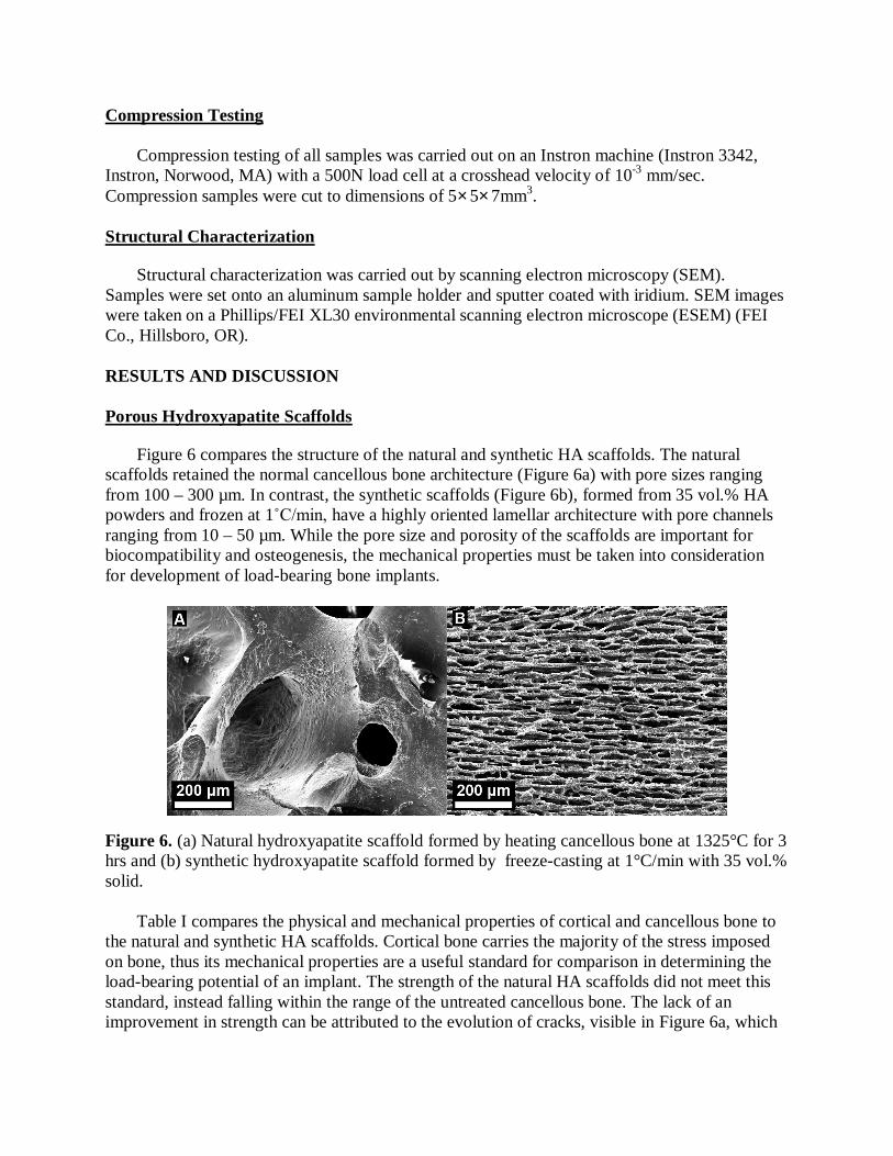
Figure 6 compares the structure of the natural and synthetic HA scaffolds. The natural scaffolds retained the normal cancellous bone architecture (Figure 6a) with pore sizes ranging from 100 – 300 µm. In contrast, the synthetic scaffolds (Figure 6b), formed from 35 vol.% HA powders and frozen at 1˚C/min, have a highly oriented lamellar architecture with pore channels ranging from 10 – 50 µm. While the pore size and porosity of the scaffolds are important for biocompatibility and osteogenesis, the mechanical properties must be taken into consideration for development of load-bearing bone implants.
Figure 6. (a) Natural hydroxyapatite scaffold formed by heating cancellous bone at 1325°C for 3 hrs and (b) synthetic hydroxyapatite scaffold formed by freeze-casting at 1°C/min with 35 vol.% solid.
Table I compares the physical and mechanical properties of cortical and cancellous bone to the natural and synthetic HA scaffolds. Cortical bone carries the majority of the stress imposed on bone, thus its mechanical properties are a useful standard for comparison in determining the load-bearing potential of an implant. The strength of the natural HA scaffolds did not meet this standard, instead falling within the range of the untreated cancellous bone. The lack of an improvement in strength can be attributed to the evolution of cracks, visible in Figure 6a, which

may have developed during the heating process. The Young’s modulus, however, showed an improvement, exhibiting stiffnesses of 0.1 – 1.2 GPa versus stiffnesses of 0.1 – 0.3 GPa for untreated cancellous bone. This is due to the creation of a contiguous, hard mineral network formed during sintering. The synthetic HA scaffolds were up to an order of magnitude stronger and stiffer than the natural ones, albeit with pores up to an order of magnitude smaller, a necessary tradeoff for increased strength. A comparison of the properties in Table I shows that the synthetic scaffolds have properties similar to those of natural cortical bone. Tailoring the porosity, density, strength, and stiffness of the freeze-casted scaffolds to match natural bone can be accomplished by altering the initial slurry properties and freezing-rates during the freeze-casting process. These effects are shown in Figure 7. As seen in Figure 7a, increasing the volume fraction of HA, increased both the strength and stiffness of the freeze-casted scaffolds. Likewise, Figure 7b shows an increase in strength and stiffness as the freezing rate was increased. Still, the porosity of the scaffolds showed a general decrease from 70% to 50% and the density of the scaffolds showed a general increase from 0.9 g/cm3 to 1.7 g/cm3 as the compressive mechanical properties were improved by increasing the HA volume fraction. At different freezing rates, however, the porosity and density of scaffolds with equal HA volume fractions did not seem to change significantly (± 5%) as the compressive mechanical properties were improved.
Table I. Physical and mechanical properties of hydrated cortical [3] and cancellous bone [4], and natural (heated bovine cancellous bone) and synthetic (freeze-casted) hydroxyapatite (HA). ( = bulk density, = compressive strength, E = Young’s modulus).
Vol. % mineral
Porosity (%)
Pore size (µm)
ρ (g/cm3)
σ (MPa)
E (GPa)
Cortical bone 30-40 5 – 10 10 – 50 2.0 110 – 150 18 – 22
Cancellous bone 30-40 75 – 85 300 – 600 0.2 – 0.5 2 – 6 0.1 – 0.3 Natural HA scaffolds 100 50–90 100–600 0.3–1.3 0.4–9.7 0.1–1.2
Synthetic HA scaffolds 100 50–70 10–50 0.9–1.7 0.7–95.1 0.1–19.2
Figure 7. Compressive strength and Young’s modulus of freeze-casted hydroxyapatite scaffolds: (a) constant freezing rate (5°C/min) with varying solid slurry loadings and (b) constant solid loading (30 vol.%) with varying freezing rates.
0
10
20
0
20
40
60
80
100
HA (20 vol %) HA (30 vol %) HA (35 vol %)
Mod
ulus
(GPa
)
Stre
ngth
(MPa
)
(a)
Strength (MPa) Modulus (GPa)
0
10
20
0
20
40
60
80
100
HA (1 C/min) HA (5 C/min) HA (10 C/min)
Mod
ulus
(GPa
)
Stre
ngth
(MPa
)
(b)
Strength (MPa) Modulus (GPa)

Other than porosity and compressive mechanical properties, pore geometry and surface roughness of the porous scaffolds are important to consider for potential bone implant materials. Fu et al. reported that cellular, as opposed to lamellar, pore architectures were much better at supporting the proliferation of pre-osteoblastic cells in vitro [22]. However, in a parallel study, Fu et al. determined that lamellar architectures yield higher compressive strength than cellular structures of similar overall porosity [24]. This suggests that, although the cellular-type architecture of the sintered cancellous scaffolds (Figure 6a) may be better suited for cell proliferation and potential bone ingrowth, the lamellar-type freeze-casted scaffolds (Figure 6b) are better suited for potential load-bearing applications requiring higher compressive strength and stiffness. In addition, the lamellar-type freeze-casted scaffolds have much higher surface roughness than the sintered cancellous bone scaffolds. High surface roughness is desirable from a mechanical perspective because the rough surfaces of adjacent lamellae may help reduce fracture from shearing, thereby increasing the ultimate strength. Furthermore, interlamellar ceramic bridges that are known to occur in freeze-casted scaffolds (Figure 6b) may add toughness to the scaffolds by reducing local effects of shear stresses.
Polymer infiltrated scaffolds
Table II compares the physical and compressive mechanical properties of the natural HA
scaffolds, PMMA, and the natural HA-PMMA composites The natural HA-PMMA composite exhibited a strength and Young’s modulus of 55 MPa and 4.5 GPa, respectively - much stronger than natural cancellous bone. The strength of the natural HA-PMMA composite, however, is noticeably lower than that of pure PMMA, possibly due to the lack of interfacial bonding. Figure 8 illustrates this lack of bonding where there are visibly smooth channels that have been vacated by the sintered cancellous bone.
Figure 8. SEM image PMMA infiltrated natural hydroxyapatite scaffold. Circled in red is a smooth channel formerly occupied by part of the natural scaffold.
Figure 9 shows images of freeze-casted HA scaffolds infiltrated with PMMA before and after compression testing. Based on preliminary results, the synthetic HA-PMMA composites, having an initial slurry concentration of 20 vol.% HA frozen at 1°C/min exhibited a strength ( of 42 MPa and a Young’s modulus (E) of 0.8 GPa. Compared to the original porous scaffolds (20 vol.% HA, frozen at 1°C/min) before PMMA infiltration (=3.2, E = 0.4 GPa), the infiltrated synthetic HA-PMMA composites showed an order of magnitude increase in strength and more

than a 2-fold increase in modulus. Regardless, the small voids seen in Figure 9a suggest that the PMMA did not fully infiltrate the freeze-casted scaffolds. And, as seen in Figure 9b, there is significant delamination of the synthetic HA-PMMA composite. The inorganic HA phase of the synthetic composites experienced brittle failure, apparent by the crumbling of HA ceramic within the buckling PMMA layers (Figure 9b). This indicates a lack of interfacial bonding between the HA and PMMA layers. Table II. Physical and compressive mechanical properties of natural HA scaffolds, pure PMMA, and natural HA-PMMA composites. ( = bulk density, = compressive strength, E = Young’s modulus).
(g/cm3)
(MPa) E
(GPa) Natural HA scaffold 0.8 4.5 0.6
PMMA 1.2 101 2 Natural HA scaffold + PMMA 1.5 55 4.5
Figure 9. (a) Synthetic freeze-casted hydroxyapatite (HA) scaffold infiltrated with PMMA. (b) Fracture surface of the synthetic HA-PMMA composite after compressive failure. The light bands are the inorganic HA phase and the dark bands are the organic PMMA.
Although the synthetic HA-PMMA composite showed improved mechanical properties, it was still weaker than the natural HA-PMMA composite. This can most likely be attributed to the continuous polymer phase that is able to form in the natural scaffold as opposed to the laminated structure found in the synthetic scaffolds. Improving the interfacial bonding at the polymer-HA boundary is a necessary step to designing a higher performance scaffold. To promote bonding between the layers, various chemical grafting techniques are currently being explored that may result in similar HA-PMMA composites with improved mechanical properties. Munch et al. has shown that the strength and toughness of Al2O3-PMMA hybrid composites were significantly improved by chemically grafting a methacrylate group on the ceramic surfaces before polymer infiltration [33]. Applying a similar concept, the HA-PMMA composites discussed here may exhibit improved strength and toughness with the introduction of chemically grafted interfacial surfaces and possessing the added advantage of resorbability and bioactivity that Al2O3 lacks [40].

CONCLUSIONS Two different types of hydroxyapatite scaffolds, natural (heated bovine femur cancellous
bone) and synthetic (freeze-casted hydroxyapatite (HA) powders) were fabricated and subsequently infiltrated with a polymer phase (PMMA). The porous synthetic scaffolds with lamellar microstructures exhibited compressive mechanical properties superior to the natural scaffolds with highly porous cellular microstructures. A decrease in porosity and pore size was determined to be a necessary tradeoff for increased compressive strength and stiffness. In each case, the natural and synthetic scaffolds exhibited a notable increase in strength and modulus upon infiltration with PMMA. Nonetheless, both the natural and synthetic HA-PMMA composites lacked interfacial bonding between the inorganic HA and the organic PMMA phases. Work is in progress to enhance the interfacial bonding through surface modification and chemical grafting of the inorganic HA phase.
Adequate porosity is desirable in bone implants to promote osteogenesis and bone ingrowth. Therefore, filling the pores of a bone implant with a polymeric phase may seem counter-productive. However, HA-polymer composites may be useful for total bone replacement applications, where bone ingrowth is not possible or large portions of bone must be replaced to bear the entire load of previously diseased or injured tissue over long periods of time. Furthermore, polymer infiltration with biodegradable polymers, such as PLA, may give an implant high strength and toughness initially, while over time a biodegradable polymer may dissolve, allowing for natural bone ingrowth. In this way, bone implants may be created that have both acceptable mechanical properties initially required for load-bearing applications and the physical surface properties required for osteogenesis. Preliminary results have shown that synthetic HA-polymer composites have good potential for applications as load-bearing bone implants/replacements.
ACKNOWLEDGMENTS We thank Ryan Anderson (CalIT2, UCSD) for the help in scanning electron microscopy. This work is supported by the National Science Foundation, Ceramics Program Grant 1006931. REFERENCES
1. S. Weiner, H.D. Wagner, Annu Rev Mater Sci 28, 271-298 (1998). 2. T.M. Keaveny, E.F. Morgan, G.L. Niebur, O.C. Yeh, Annu Rev Biomed Eng 3, 307-333
(2001). 3. E. Novitskaya, P.-Y. Chen, S. Lee, A. Castro-Ceseña, G. Hirata, V. Lubarda, J. McKittrick,
Acta Biomater 7(8), 3170-3177 (2011). 4. P.-Y. Chen, J. McKittrick, J Mech Behav Biomed Mater 4(7), 961-973 (2011). 5. Y. Kuboki, H. Takita, D. Kobayashi, E. Tsuruga, M. Inoue, M. Murata, et al., J Biomed
Mater Res 39(2), 190-199 (1998). 6. Y.S. Chang, H.O. Gu, M. Kobayashi, M. Oka, J Arthroplasty 13(7), 816-825 (1998). 7. J.X. Lu, F.K. Anselme, P. Hardouin, A. Gallur, M. Descamps, B. Thierry, J Mater Sci 10(2),
111-120 (1999). 8. S.F. Hulbert, F.A. Young, R.S. Mathews, J.J. Klawitter, C.D. Talbert, F.H. Stelling, J
Biomed Mater Res 4(3), 433-456 (1970).

9. B.S. Chang, C.K. Lee, K.S. Hong, H.J. Youn, H.S. Ryu, S.S. Chung, K.W. Park, Biomaterials 21(12), 1291-1298 (2000).
10. J.R. Woodard, A. J. Hilldore, S.K. Lan, C.J. Park, A.W. Morgan, J.C. Eurell, S.G. Clark, M.B. Wheeler, R.D. Jamison, A.J.W. Johnson, Biomater 28(1), 45-54 (2007).
11. S.S. Liao, F.Z. Cui, Q.L. Feng, J Biomed Mater Res B 69B(2), 158-165 (2004). 12. Z. Xiong, Y. Yan, S Wang, R. Zhang, C. Zhang, Scripta Mater 46(11), 771-776 (2002). 13. C.Y. Lin, N. Kikuchi, S.J. Hollister, J Biomech 37(5), 623-636 (2004). 14. J.M. Taboas, R.D. Maddox, P.H. Krebsbach, S.J. Hollister, Biomater 24(1), 181-194 (2003). 15. H.R.R. Ramay, M. Zhang, Biomater 25(21), 5171-5180 (2004). 16. S. Deville, Adv Eng Mater 10(3), 155-169 (2008). 17. M. Azami, F. Moztarzadeh, M. Tahriri, J Porous Mater 17, 313-320 (2010). 18. S. Blindow, M. Pulkin, D. Koch, Adv Eng Mater 11(11), 875-884 (2009). 19. S. Deville, E. Saiz, A.P. Tomsia, Biomaterials 27(32), 5480-5489 (2006). 20. Q. Fu, M.N. Mohamed, F. Dogan, B.S. Bal, Biomed Mater 3(2), (2008). 21. Q. Fu, M.N. Rahaman, B.S. Bal, R.F. Brown, J Mater Sci-Mater M 32(2), 86-95 (2009). 22. E.J. Lee, Y.H. Koh, B.H. Yoon, H.E. Kim, H.W. Kim, Mater Lett 61(11-12), 2270-2273
(2007). 23. T. Moritz, H.-J. Richter, J Am Ceram Soc, 89(8), 2394-2398 (2009). 24. Y. Suetsugu, Y. Hotta, M. Iwasashi, M. Sakane, M. Kikuchi, T. Ikoma, T. Higaki, N. Ochiai,
J. Tanaka, Key Eng Mater 330-332, 1003-1006 (2007). 25. T.Y. Yang, J.M. Lee, S.Y. Yoon, H.C. Park, J Mater Sci-Mater M 21(5), 1495-1502 (2010). 26. B.H. Yoon, C.S. Park, H.E. Kim, Y.H. Koh, Mater Lett 62(10-11), 1700-1703 (2008). 27. Y. Zhang, K. Zuo, Y.-P. Zeng, Ceramics International 35, 2151-2154 (2009). 28. K.H. Zuo, Y.P. Zeng, D.L. Jiang, Mater Sci Eng C-Mater Bio 30(2), 283-287 (2010). 29. K.H. Zuo, Y.A. Zhang, Y.P. Zeng, D.L. Jiang, Ceram Int 37(1), 407-410 (2011). 30. Wegst, U.G.K., Schecter, M., Donius, A.E., and Hunger, P.M. Philoso T R Soc A 368, 2099-
2121 (2010). 31. M.C. Flemings, Solidification Processing, 1st ed. (McGraw-Hill, New York, 1974) p. 100. 32. S. Deville, E. Saiz, A.P. Tomsia, Acta Mater 55(6), 1965-1974 (2007). 33. M.E. Launey, E. Munch, D.H. Alsem, H.B. Barth, E. Saiz, A.P. Tomsia, R.O. Ritchie, Acta
Mater 57(10), 2919-2932 (2009). 34. E. Munch, M.E. Launey, D.H. Alsem, E. Saiz, A.P. Tomsia, R.O. Ritchie, Science
322(5907), 1516-1520 (2008). 35. F.J. Martinez-Vazquez, F.H. Perera, P. Mirand, A. Pajares, F. Guiberteau, Acta Biomater
6(11), 4361-4368 (2010). 36. X. Miao, W.-K. Lim, X. Huang, Y. Chen, Materials Letters 59, 4000-4005 (2005).M.
Peroglio, L. Germillard, C. Gauthier, L. Chazeau, S. Verrier, M. Alini, J. Chevalier, Acta Biomater 6(11), 4369-4379 (2010).
37. M. Peroglio, L. Germillard, C. Gauthier, L. Chazeau, S. Verrier, M. Alini, J. Chevalier, Acta Biomater 6(11), 4369-4379 (2010).
38. S. Sharifi, Y. Shafieyan, H. Mirzadeh, S. Bagheri-Khoulenjani, S.M. Rabiee, M. Imani, M. Atai, M.A. Shokrgozar, A. Hatampoor, J Biomed Mater Res A 98A(2), 257-267 (2011).
39. G. Pezzotti, S.M.F. Asmus, L.P. Ferroni, S. Miki, J Mater Sci-Mater M 13(8), 783-787 (2002).
40. L.L. Hench, J Am Ceram Soc 74(7), 1487-1510 (1991).