potential services performance of lubricating oils. laboratory evaluation
TRANSCRIPT
Potential Service Performance of Lubricating Oils Laboratory Evaluation
GEORGE W. WATERS' AND ELDER C. LARSON Wood River Research Laboratories, Shell Oil Co., Inc., Wood River, Ill.
The corrosion and stability apparatus and method of test are introduced as means for the preliminary evaluation of the quality of lubricants. The distinctive feature of the test is the use of a felt wiping action on the bearing surface to simulate the action of the journal in the engine. Appli- cation of the test to twenty oils upon which
T IS universally agreed that the ultimate criterion of I the quality of a lubricant is efficient performance in the engine for n-hich i t is designed. This fact will remain per- manent, since the development of bench methods, n-hich seek optimum control of variables and elimination of extraneous factors, inevitably leads to departures from the actual engine. I t is scarcely possible that accurate reproduction of an engine in its entire scope will ever be realized in a noncombustion type of laboratory apparatus.
The existence of many laboratory apparatus and methods of test, several of comparatively recent origin, testifies to the need for means of evaluating oils which can cope economically
York, N. Y. 1 Present address, Shell Oil Company, Ino.. 50 West 50th St., New
extensive engine data have been reported establishes it as capable of predicting the oxidation stability and potential corro- sivity of lubricants with accuracy sufficient to warrant the use of the test as a useful and reliable tool, in both research and control, to eliminate much of the more costly and time-consuming engine testing.
and practically with the great bulk of testing required either in the development of improved lubricants or in the control of oils in production. Such service is far too formidable for even small-scale test engines. When laboratory tests are available in such numbers, the presentation of a new a p paratus perhaps requires justification. It is generally true that each test was developed specifically to evaluate a par- ticular feature which the originators deemed important and worthy of emphasis. The tests, existent prior to the d e velopment of the present apparatus, represented a wealth of knowledge and experience from which could be selected the outstanding feature of individual cases, for incorporation into the new corrosion and stability apparatus. For example, severe conditions of aging lead to the simultaneous occurrence
REPCTIDN VESSEL FLOWMETER SCRUBBERS FOR VENTING GAS
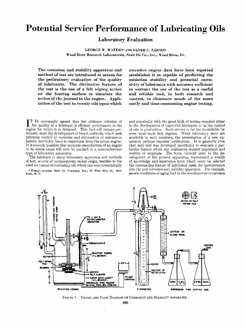
FIGURE 1. DETAIL AND FLOW DIAQRAM OF CORROSION AND STABILITY APPARATUS 550
A N A L X T I C A L E U I T I O N
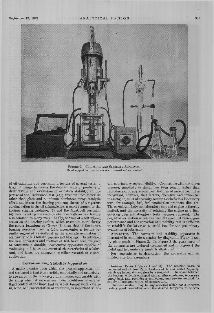
FIGURE 2. CORROSION AND STABILITY APPARATUS Metal support for reaction chamber removed and rotor raised
of oil oxidation and corrosion, a feature of several tests; a hrge oil charge facilitates the determination of products of deterioration and evaluation of oxidation stahility, an ob- jective of the Underwood test ( 2 1 ) ; freedom from materials other than glass and aluminum eliminates stray catalytic effects and lessens the cleaning problem; the use of a vigorous stirring action in the oil acknowledges a merit common to the Indiana stirring oxidation (a and the MacCoull corrosion (6) tests; venting the reaction chamber with air is a feature also common to many tests; finally, the use of a felt wiping sotion on the bearing surface, which resembles more closely the earlier technique of Clower (3) than that of the thrust bearing corrosion machine (IO), incorporates a feature re- cently suggested as essential in the accurate evaluation of corrosivity of oils toward copper-lead bearings. In addition, the new apparatus and method of test have been designed to constitute a durable, inexpensive apparatus capable of evaluating in 5 hours the essential characteristics of a lubri- cant, and hence are amenable to either research or control application.
Corrosion and Stability Apparatus A major premise upon which the present apparatus and
test are based is that it is possible, empirielally and artificially, to age an oil in the laboratory in a manner comparable with the aging which it experiences under conditions of service. Rigid control of the important variables, temperature, cataly- sis, time, and concentration of reactants, is important to oh-
tain satisfactory reproducibility. Compatible with the above premise, simplicity in design has been sought rather than reproduction of any mechaniral features of an engine. It is recognized, however, that factors, operative and influential in an engine, must of necessity remain extrinsic to a laboratory tat-for example, fuel, fuel combustion products, dirt, etc. The correlation between laboratory test and engine is thereby limited, and the necessity of retaining the engine as a final criterion over all laboratory tests becomes apparent. The degree of correlation which has been obtained between engine performance and the corrosion and stability test is sufficient to establish the latter as a useful tool for the preliminary evaluation of lubricants.
APPARATUS. The corrosion and stahility apparatus is illustrated in complete assembly by diagram in Figure 1 and by photograph in Figure 2. In Figure 3 the glass parts of the apparatus are pictured dismantled and in Figure 4 the metal and felt units are similarly illustrated.
For convenience in description, the apparatus can he divided into four assemblies.
Reaclim Vessel (Figures 1 and 3). The reaction vessel is fashioned out of two Pyrex beakers of 1- and 2-liter capacity, which are joined at their rims by a ring seal. The space between the beakers, which is equipped with a reflux condenser, serves e8 a vapor bath and provides a convenient and precise method for s~pp ly of beat and control of temperature.
The heat medium may be any material which has a constant boiling point coincident with the desired temperature of test.

552 I N D U S T R I A L A N D E N G I N E E R I N G C H E M I S T R Y Vol. 15, No. 9
- FIG
in conjunction with the design of the felt wiping pad, ensures an even snd continual flow of lubricant over the bearing surface. The hearing inserts, of course, can be ?f any available metal or alloy. copper, alum- num, lead, copper-lead, cadkum-nickel, and lead-flashed copper-lead have been employed.
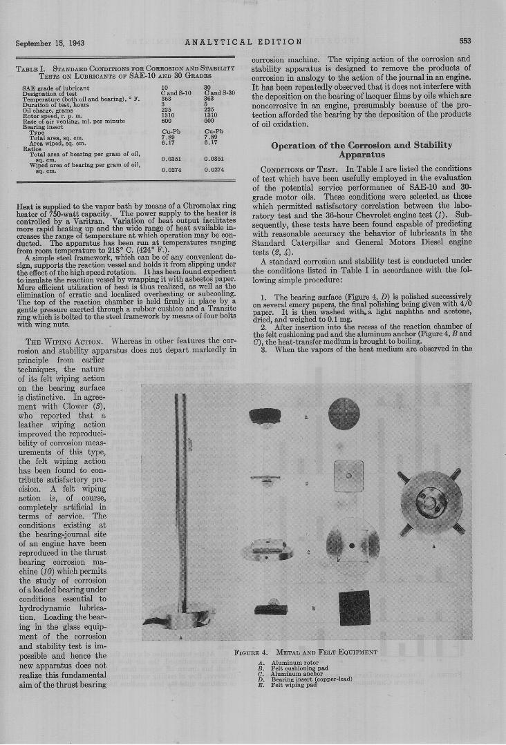
The wiping and stirring actio- are IO- vided by an aluminum-felt unit whict i s called the "rotor" (Figure 4, A). The aluminum portion of the rotor consists of a shaft which is chucked into a conven- tional, bench-type drill press. At the lower extremity of the shaft is an aluminum disk, extending np into the bottom of which is a cyhndrical recess Elaced coaxially with the disk and shaft. xtending down from the "ceiling" of the recess are alummum spikes which embed themselves in the felt wiping pad (Figure 4, E) and prevent its slipping during rotation. The felt wiping pad is fashioned out of B cylindrical pad of felt of diameter such that a snug fit is ensured with the recess in the rotor-and of sufficient thickness (0.9-1.25 em., 0.375- 0.5 inch) to extend about 0.3 om. 10.126
. .. . purified by drying and redistillation, is most frequently used. However, wide ranges of temperature have been covered in appli- cation of the apparatus by use of the following mzterials: water (212" F.), chlorobenzene (270" F.), bramobenzene (313" F.), pseudooumene (337" F.), aniline (363' F.), and naphthalene (424" F.). In the bottom of the inner beaker there is a square recess, slightly larger than 2.8 X 2.8 cm. (1.125 X 1.125 inches) End about 0.6 em. (0.25 inch) in depth. The reaction chrtmber is covered by an essentially flat glass lid, and a seal is effected by a flat ground-glass contaot between the lip of the reaction cham- ber and the cover. Through the center of the cover prtsses the shaft of the aluminum rotor. Also from the center of the cover extends a lead to a water aspirator which serves to prevent fumes of deteriorating oil from being dispersed into the laboratory. Displaced to one side of the central opening through the cover there is a female ground-glass joint which accommodates a com- bined thermocouple well and an air inlet to the reaction chamber. Through this opening, samples of oil can he taken, if desired, with only momentary interruption of operation. The over-all volume of the reaction chamber is approximately 850 to 900 ml.
Wiping and Stirring Assembly (Figures 1 and 4). Into the square recess in the bottom of the reaction chamber fits the aluminum bearing insert holder, called the "anchor" (Figure 4, 0, which consists of an duminum disk. from the bottom of which extends a square protrusion and into the toD of which is sunk a
ture prevents rotation of the anchor duhng operation and holds the bearing insert stationary during a run. The recess in the top of the anchor accommodates the square bearing inserts, 2.8 x 2.8 cm. (1.120 X 1.120 inches). and of thickness 0.25 em. (0.1 inch), sufficient for the surface'of the hearing to extend about
axially through the anchor. A bole bore$ Derrrendicularlv
:eneral, the nature of the felt used is not ritical a limiting factor being that i t shall tot dis)intewate during the course of a run. 'Jormallv. SAE F3 erav backcbeck felt (95 o 100 per cent wGol)" is used; SAE F1 vhite hackcheck (100 per cent wool) has been ound satisfactory.
On the face of the pad, which wipes the tearing insert during operation, is cut a pat- ern which is represented in the diagram ,f Ficure 1. and shown hv nhotoeranh in pigur; 4, E.' Briefly, this Ca thn , which is ut most conveniently with a ramr blade, onsists of two perpendicular, triangularly irismatic trouehs which extend alone diam- ters of the susace. In addition to rhe two
allows a complete change of ahosphkrc approximateiy once each minute.
For simplicity and con- venience the corrosion and stability apparatus employs a conven- tional, bench-type drill press. Power is furnished by means of a '/a-hp. motor. Speed of revolution of the rotor is determined by the Characteristics of the motor and reduction pulleys provided a8 standard features of the equipment. For standard testing, a speed of 1310 r. p. m. is used. However, variation has been in- vestigated a t 660 and 2410 r. p. m. Constancy of rotation is readily maintained within satisfactory limits (* 1 per cent at 1310 r. p. m.) and is checked periodically by means of a tachometer.
Moounting Accessories (Figure 2).
September IS, 1943 A N A L Y T I C A
TABLE I. STANDARD CONDITIONS FOR CORROSION AND STAFXLITY TESTS ON LUBRICANTS OF SAE-10 AND 30 GUDES
SAE grade of lubricant Deaignatian of test Temperature (both oiland bearing), e F. Duration of test, hours Oil charge. rams Rotor e p & , r. P. m. Rate of air venting. ml. per minute Bearing insert
T Y P ~ Total *rea w. Om. A C ~ = wiped, 89. cm.
Total are& of bearkg per gram of oil.
Wiped mea of bearing per gram of oil,
Ratios
89. cm.
$9. om.
10 C and 9-10 363 3 225 1310 600
Cu-Pb 7.89 6.17
0.0351
0.0274
ao C snd 9-30 363 5 225 1310 600
Cu-Pb 7.s9 8.17
0.0351
0.0214
Ikat issupplied to the vapor bath tiy means ofn (:liromolau rinn heater oi 750-watt capacity. The power supply to the heater i i controlled bv a Varitran. Variation oi heat O U l D U t fwilitates rn& ranid lkatina UD and the wide range of heaE available in-
~~
A sim~le ste&framework. whioh &n he df any convenient de-
.__ ~
More efficient utilization of hcat is &uskaliqed, BS well is:the elimination of erratic and localiaed overheating or snbcoohng.
L E D I T I O N ss:
corrosion machine. The wiping action of the corrosion anc . ,.1., I . .. J...-.J I^ I *I.- -"-A.."*" ~
3
I scaaiuzy apparazus 1s ueugueu re iu~ve uiti ~ ' L V U U G Y D vf corrosion in analogy to the action of the journal in an engine. It has been repeatedly observed that it does not interfere with the deposition on the bearing of lacquer films by oils which are noncorrosive in an engine, presumably because of the pro- tection afforded the bearing by the deposition of the products of oil oxidation.
Operation of the Corrosion and Stability Apparatus
CONDITIONS OF TEST. In Table I are listed the conditions of test which have been usefully employed in the evaluation of the potential service performance of SAE-IO and 30- grade motor oils. These conditions were selected as those which permitted satisfactory correlation between the labo- ratory test and the 36-hour Chevrolet engine test (1). Suh- sequently, these tests have been found capable of predicting with reasonable accuracy the behavior of lubricants in the Standard Caterpillar and General Motors Diesel engine tests (2,4).
A standard corrosion and stability test is conducted under the conditions listed in Table I in accordance with the fol- lowing simple procedure:
1. The bearing surface (Figure 4, D ) is olished successively on several emery papers, the final polishing geing given with 410 paper. It is then washed w i t h a light naphtha and acetone, dried. m d weiehed to 0.1 me. ~~~ ~~D~~~~~ ~~ ~
with wing nuts. 2. After insertion into t i e recess of the reaction chamber of
principle from earlier techniques, the nature of its felt wiping action on the bearing surface is distinctive. In agree- ment with Glower @), who reported that a leather wiping action improved the reproduci- bility of corrosion meas- urements of this type, the felt wiping action has been found to con- tribute satisfactory pre- cision. A felt wiping action is, of course, completely artificial in terms of service. The conditions existing at the bearing-journal site of an engine have been reproduced in the thrust bearing corrosion ma- chine (IO) which permits the study of corrosion of a loaded bearing under conditions essential to hydrodynamic lubrica- tion. Loading the bear- ing in the glass equip- ment of the corrosion and stability test is im- possible and hence the new apparatus does not realize this fundamental aim of the thrust bearing
,. ,
P
A
FIGURE 4. METAL AND FELT EQUIPMENT
554 I N D U S T R I A L A N D E N G I N E E R I N G C H E M I S T R Y Vol. 15, No. 9
TABLE 11. CORRELATION OF C AND 5-30 w m THE 36-Hon~ CHEVROLET ENGINE TEST (On the basis of the four SAE correlation oils of 30-viscosity grade)
SAE Correlation SAE Correlation SAE Correlation Oil B-1 Oil B-2 Oil B-3
SAE Correlation Oil B-4 Property
Bearing weight loss, mg. per sq. om.
Increase in neutral- ization No mg. of KOH per ;ram
C a?d S-30 0 . 8 * 0.16 (19%) 4 . 8 * 0 . 4 (8.3%) 1.20 * 0 . 0 4 ( 3 . 3 % ) Engine test 2 . 3 5 . 3 1 . 6 Rating C and S-30 1 4 2 Rating,' engine 2 4 1
Increase in viscosity at looo F., 8. C. seconds
C and S-30 68 * 12 (18%) 160 * 14 (8.8%) 24 * 2 (8 .4%) Engine test 490 373 91 Rating, C and S-30 2 3 1 Rating, engine 3 2 1
Naphtha-insolubles, % by weight
C and S-30 0 .oo-0.01 Engine test 1 .72 Rating C and S-30 - Rating: engine 3
0.01-0.02 0 .78
0.00-0.01 0.45
1.17 f 0.01 (0.9%) 2 .81
4 - 2
- 1 4
Chloroform-solubles, % by weight
C and S-30 < 0.01 1.38
3 -
< 0.01 0 .48
0.00-0.01 0 .12
1.16 A 0 . 0 1 (0 .9%) 2 .57
4 Engine t i i t Rating C and 9-30 Rating: engine
- 2
- 1 4
Increase in Conradson carbon residue, '% by weight
C and 9-30 0 .17 2 .16
1 2
0.92 * 0 . 8 (8.7%) 0 .34 * 0 .04 (12%) 2 .25 1 .29
3 2 3 1
1.02 * 0 . 0 3 2 .56 (2 .9%)
4
- . _... Engine test Rating, C and S-30 Rating, engine 4
reflux condenser, 225 grams of the test oil are introduced into the reaction chamber. 4. The oil is judged to be sufficiently heated for introduction
of the bearing when vapors are again observed in the reflux con- denser. The weighed bearing is then fitted into position. In the case of opaque oils, a Nessler tube is conveniently employed as a spyglass, facilitating visual observation when the closed end is held down against the anchor.
After the bearing has been put into place, the apparatus is com letely assembled. The rotor in which a fresh felt wiping pad has gee, placed is rested on the bearing (Figure 4, A and E ) , and the cover (Figure 3, B) , rubber cushioning ring, and Transite clamping ring are assembled and clamped into position with the four wing nuts (Figure 2). The shaft of the rotor is chucked into the drill-press spindle and the rotor is gently lowered until it rests on the bearing. At this point the motor is started to test the apparatus; if everything is in order, operation will proceed smoothly. Occasionally the wiping pad will become displaced from its recess in the rotor; this can be detected when the stirring mechanism is started and can be immediately rectified. The combined thermocouple well and air inlet is set into place, and, to avoid freezing, its ground-glass joint is lubricated with the oil under test. The stirrer should not be set into motion with the rotor raised, since the fins may not clear the thermocouple well and breakage will result.
A few minutes, about 10 to 15, are allowed after assembling the apparatus for the oil to come back to temperature after cooling during exposure to atmosphere during the introduction of the bearing. Again this can be judged by appearance of reflux in the condenser. Temperature readings are taken on a Leed? & Northrup indicating potentiometer, the thermocouple havlng been set in place. To obtain representative temperature meas- urements, stirring should be in operation, since the thermocouple well may not be sufficiently immersed in the oil otherwise. When reflux is again well up in the condenser, the air flow is started and adjusted to the desired rate by means of the calibrated mano- metric flowmeter, the stirring started, and zero time recorded. The equilibrium temperature is usually attained in from 3 to 5 minutes. Finally, the suction is supplied to the exit from.the reaction chamber (by water aspirator) to prevent dlspersing into the laboratory the fumes of deteriorating oil.,
Normally very little attention is required by the corrosion and stability apparatus during the course of the run. Routine checks are made periodically of the temperature, air flow, and water flow through the condenser and any necessary adjustments
5.
6.
7.
36-UWR CUEVROLET E N G l E TEST C 4HD 5 - 3 0 TEST
Y)
(n
L
B 5
i 1
I . . made.
8. At the termination of a run, the supply of heat to the vapor bath is discontinued, the air flow is stopped, and the suction which has drawn off vapors from the reaction vessel is cut off. However, flow of cooling water through the condenser is allowed to continue until the heat medium has cooled well below boiling.
1 ' 1 8'2 8.3 8-4 1 ' 1 8.2 8.3 8.4
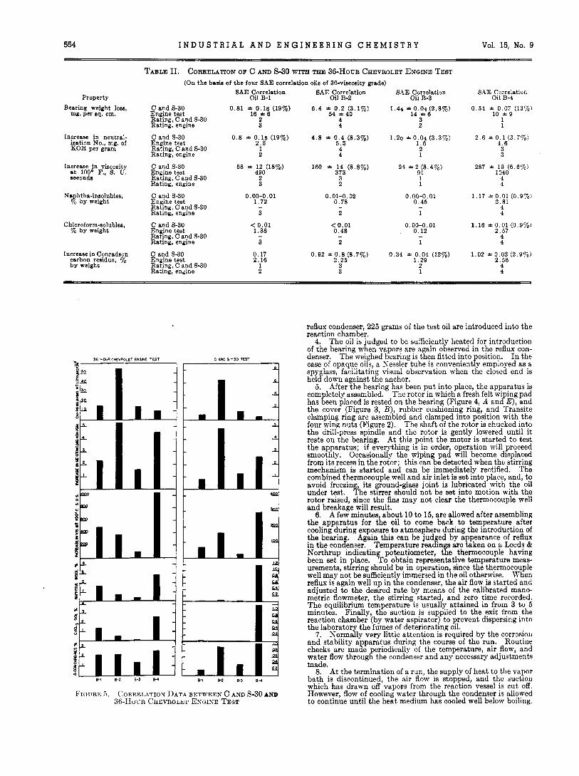
FIGURE 5 . CORRELATION DATA BETWEEN C AND S-30 AND 36-HOK:R CHEVROLET EXGINE TEST
September 15, 1943 A N A L Y T I C A L E D I T I O N 555
TABLE 111. CORRELATION OF c AND s-10 WITH THE 36-HOUR CHEVROLET ENGINE TEST (On the basis of the four SAE correlation oils of 10-viscosity grade)
SAE Correlation SAE Correlation Property Oil B-11 Oil B-12
Bearing weight loss, C and S-10 0 .79 f 0.02 (2.5%) 1 . 7 * 0 . 2 (12%) mg. per sq . cm. Engine test 12 * 3 50 f 2 8
Rating, C and S-10 2 4 Rating, engine 3 4
Increase in neutral- C and S-10 0 . 9 * 0 . 1 (11%) 2 . 8 * 0 . 2 (7.1%) ization No., mg. of Engine test 1.8 6 . 4 KOH per gram Ratina, C and S-10 1 4
Rating, engine 1 4
Increase in viscosity C and S-10 24 f 3 (12%) a t 100" F., S. U. Engine test 316 ,3 8 e c o n d s Rating, C and S-10 1
Rating, engine 4
38 * 5 (13%) 198.1
3
Naphtha-insulubles. C and S-10 0.04 * (< 0.005) 0.32 f 0.02 (6.3%) % by weight Engine test 2 .42 1.16,
Rating, C and S-10 1 3 (2) Rating, engine 4 2 (2)"
Chloroform-solublea, C and 9-10 0.015 * 0.005 0 .27 f 0.01 (3.7%) % hy weight Engine test 1 .68 0,49,
Rating, C and 9-10 1 3 (2) Rating, engine 3 2
Increase in Conradson C and S-10 0 12 f 0.02 (17%) , 0.376 f 0 . 0 0 5 ( 1 . 3 % ) carbon residue, yo Engine test 2 .26 1 .89 by weight Rating, C and 9-10 1 3
Rating, engine 4 3
Figures in parenthesea represent relative ratings i f oil B-11 is eliminated from consideration.
SAE Correlation Oil B-13
0 .8 f 0 . 2 (25%) 8 * 3
2 2
1.25 * 0.05 (4 .0%) 1.95
2 2
28 f 2 ( 7 . 1 % ) 47.1
3 1
0.22 f 0 . 0 2 (9.1%)
2 (1) 1 (1)"
0 . 1 q
0 .12 * 0.04 (33%) 0.95
1 1
SAE Correlation Oil B-14
0.24 f 0.05 (21%) 2 f l
1 1
1 . 7 *00 .3(18%) 4 . 5
3 3
23 f 6 (26%) 162.3
1 A L
0.62 f 0.02 (3 .2%) 1 .95
4 (3)' 3 (3)a
0 .58 *0 .04 (6 .9%)
4 (3)a
0 . 4 f 0 . 1 (23%) 1 .67
4 2
4' $?a
The apparatus is disassembled immediately, arid the oil is si- phoned from the reaction vessel. These manipulations are made immediately a t the completion of a run, since it is considered im- portant to keep a t a minimum the "overexposure" of the bearing to the hot deteriorated oil.
9. After removal from the apparatus, the bearing insert is washed in solvents as it was prior to its initial weighing. Adher- ing particles of sludge are removed by gentle swabbing with cot- ton, but no abrasion severe enough to cause erosion of metal is employed. When clean, the surface of the bearing is examined visually for evidence of erosion or uneven wiping. Erosion is indicated by deep concentric scratches in the surface, whereas uneven wiping results in polished areas unevenly distributed on the "high" areas of the surface. When dry, the bearing is re- weighed to evaluate the extent of corrosion which has occurred during the run.
The aged oil is subjected to analysis for properties which are regarded conventionally as measures of extent of deteriora- tion-. g., neutralization number, saponification number-in- crease in viscosity, and naphtha-insolubles.
CLEANING THE APPARATUS. The apparatus is thoroughly cleaned after each run. While still warm, the reaction vessel is first swabbed out with dry cotton. Kerosene is then introduced and the walls of the vessel are briskly rubbed with cotton. Successive washes then follow with naphtha and acetone until the solvents remain uncolored. The cover, rotor, and anchor are likewise washed with kerosene, naph- tha, and acetone. Both felt cushioning pad and felt wiping pad are discarded after each run.
Occasionally i t is necessary to employ more drastic clean- ing procedures. The metal parts can be abraded with steel wool, care being taken to rinse off all metal particles after such treatment. Steel woo1 is never used on the re- action vessel; rather a prolonged exposure to bichromate- sulfuric acid cleaning solution is employed. This can be effectively accomplished by filling the vessel with the acid and bringing the vapor bath to reflux.
10.
Experimental Results I n their development the standard corrosion and stability
tests were correlated with the 36-hour Chevrolet engine test, since considerable data (7') are available from the recent cor- relation program carried out among several laboratories on this engine test under the supervision of the subcommittees
36-HOUR CMVROLET ENGINZ TEST c w 9-00 TEST
- I L Y p' 1 t
i 4 P p c
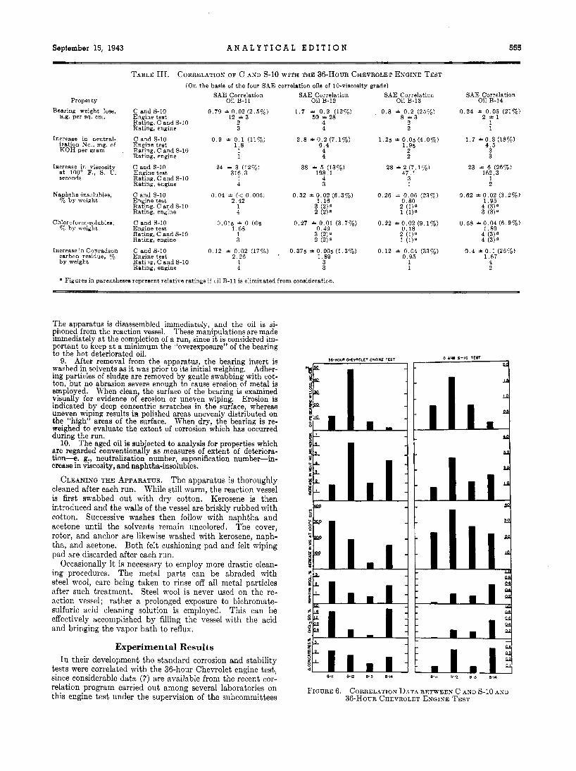
FIGURE 6. CORREL.4TION DATA BETWEEN c AND s-10 AXD 3 6 - H o c ~ CHEVROLET ENGINE TEST
556 I N D U S T R I A L A N D E N G I N E E R I N G C H E M I S T R Y Vol. 15, No. 9
TABLE IV. CORROSIVITY-ZONE SCHEDULE FOR JUDGING POTEN- TIAL CORROSIVITY OF LUBRICANTS FROM RESULTS OF CORROSION
AND STABILITY TESTS Weight Loss of Cu-Pb Bear-
ing Insert in C and S Test Zone Desoription SAE-10 oils SAE-30 oils
Mg. per aq. em.
osive > 1.6
of Sub-Division B of the Lubricants Division of the Society of Automotive Engineers.
ROLET EKGIXE TEST. I n Table I1 and Figure 5 are presented the correlation data for corrosion and stability on 30-grade oils and the 36-hour Chevrolet engine test.
The precision of C and S-30 is strikingly good for this type of test, as concerns both potential corrosivity and oil deterioration. Average error for these data expressed as average deviation from the mean is *8.2 per cent.
Oils B-1 and B-3 are re- versed by the laboratory test from their relative ratings in the engine in respect t o corrosivity, increase in neutralization num- ber, and increase in carbon residue, and B-1 and B-2 are reversed as concerns increase in viscosity. The reversal of B-1 and B-3 in corrosivity is not considered serious, since one third of the participating engine laboratories either rated these oils in the same order as did the C and S-30 or rated them as equal. Fur- ther, the averages for all engine laboratories on the corrosivity of these two oils separated them by only 14 per cent of the lower figure (16 mg. per sq. cm. for B-1, 14 mg. per sq. em. for B-3) which is well within the precision of the engine test. The reversal of B-1 and B-2, in respect to increase in viscosity, occurs again with two oils on which the least differentiation was
CoRREL-4TION OF C AND S-30 WITH THE 3 6 - H o u ~ CHEV-
Some reversals will be observed.
made by the engine. The C and S-30 found
most difficult the repro- duction of engine perform- ance as regards formation of sludge and insoluble bodies in these oils. It is logical that the interfering factors attributable to the fuel, fuel combustion prod- ucts, dust, and dirt, in- fluential in the engine but absent in the laboratory test, will concentrate their effect in regard to this particular manifestation of deterioration. Neverthe- less, it is evident that C and 5-30 distinguishes B-4 as the worst oil in regard t o naphtha-insolubles, chloroform-solubles, and in- crease in carbon residue.
Xeither the corrosion and stability nor the engine test rates the corrosivity of the oils in the same order as in development of neutrali- zation number. Thus, further evidence is pro- vided of the inadequacy of neutralization number as a criterion of the de- velopment of corrosivity.
CORRELATION OF C AND S-10 WITH THE 36- HOUR CHEVROLET Ex- GINE TEST. I n Table I11 and Figure 6 are pre- sented the correlation data for corrosion and
stability on 10-grade oils and the 36-hour Chevrolet engine test.
A relatively high order of precision is maintained in C and S-10; average error for these data is *13.4 per cent. Ample margin is provided to differentiate readily between oils of reason- ably different uality.
The C and 3-10 rated oils B-11 and B-13 of equal corrosivity within the precision of the test, whereas the engine test rated B-11 more corrosive than B-13. However, as can be judged from the precision figures for the engine tests (included in Table 111) the ranges in corrosivity covered by both oils are sufficient to permit a reversal.
Correlation between laboratory and engine tests on viscosity increase is poor; however, development of naphtha-insolubles, chloroform-solubles, and increase in carbon residue agree satis- factorily with the one exception of oil B-11.
As in the case of the 30-grade oils, here again there is no correla- tion between development of neutralization number and corrosiv- ity.
Tables I1 and I11 indicate that extent of corrosivity and oil deterioration in the corrosion and stability tests falls short of that in the engine test. Standard conditions have been selected deliberately to maintain deterioration in the labo- ratory test less severe than that in the engine, since the con- verse might be expected to imperil the validity of the test. Furthermore, it can be judged impossible to find a single set of conditions which would deteriorate all oils to the same extent as does the engine, since the ratio between deteriora- tion in the corrosion and stability apparatus and the engine is not constant for different oils. For example, increase in severity of conditions in the laboratory test sufficient to increase the neutralization number change for oil B-1 to its value in the engine (from 0.8 to 2.3) would be expected to Cause the deterioration of oils B-2 and B-3 to exceed that
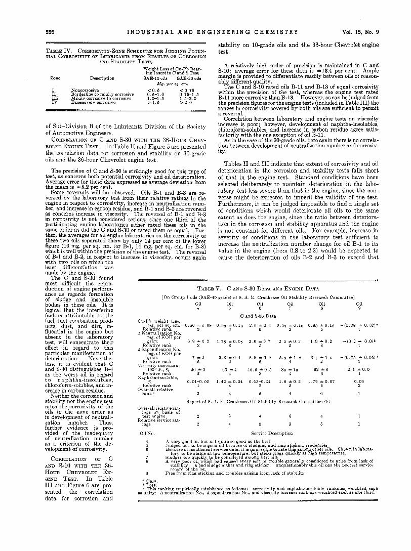
TABLE v. c AND S-30 DATA AND ENGINE DATA [On Group I oils (SAE-40 grade) of S. A . E. Crankcase Oil Stability Research Committee]
Oil Oil Oil Oil Oil Oil 4 5 6 7 8 9
C and S-30 Data Cu-Pb weight loss,
mg. per sq. cm.
A Neutralization No., mg. of KOH per gram
A Saponification No., mg. of KOH per gram
Relative rank Viscosity increase a t
100' F., yo Relative rank
Naphtha-insoluble, 70
Relative rank
Relative rank
Relative rank
0.50 1-0 .08 3
0 . 9 * 0 . 2 2
7 t 2 5
20 A 3 2
0.01-0.02 1
0.6s * 0 . 1 8 3
1 . 7 5 t0.05 3
3 . 3 t 0 . 4 2
63 * 4 4
1.42 t 0 . 0 4 4
2.0 t 0 . 3 6
2 . 8 t 0 . 7 5
6.8 1 0 . 9 5
40.5 * 0 . 5 3
0.03-0.04 2
0.34 " 0 . 1 0 2
2 . 5 f 0 . 2 5
5 , 3 ' 1 . 7 4
80 10 4
1.6 f 0 . 2 5
0.93 1 0.10 5
1.9 1 0 . 2 3
3 . 5 1 1.0 2
92 f 6 6
1.79 t O . 0 7 5
Over-all relative rank C 2 3 5 4 6
Report of S. A. E. Crankcase Oil Stability Research Committee (8)
- (0.08 1 0.02)O 1
- (0 .2 1 0 .0 )b 1
- ( 0 . 7 5 1 0 . 0 5 ) b 1
2 . 1 * o . o 1
0.04 2
I
1
1
Oil No. Service Description
A very good oil but not quite so good as the best Judged not to be a good oil because of sludging and ring sticking tendencies Because of insufficient service data, i t is impossible to rate this among other oils. Shown in labora-
Sludges too quickly to be considered among best oils A very poor oil which had caused every sort of trouble generally conside,red to arise from lack,of
unquestionably this oil has the poorest service
Free from ring sticking and troubles arising from lack of stability
? 6
7 8
9
tory to be stable a t low temperature, but sticks rings quickly a t high temperature.
stability: record of ,the lqt.
a bad sludge maker and ring sticker;
0 Gain. b Loss. C This ranking empirically established a8 follows:
as unity; A neutralization No., A saponification No., and viscosity increase rankings weighted each as one third. corrosivity and naphtha-insoluble rankings weighted each

September 15, 1943 A N A L Y T I C A L E D I T I O N 557
extent, of oil deterioration asmeasured by the proper- ties of the final oil sample.
-Oil 13- -- Oil la------ - ~ Oil Is---- d more satisfactory ex- pedient would be to meas- ure deterioration as a
Cu-Pb weight loss, mg. function of time. This js per s q . em. 0 .32 - 0 . 0 0 0 .64 17 28 - 0 . 0 5 0 38 2.36 1 0 . 0 2 4 . 3 conveniently ncliieved in
A Weutralization No., mg. corrosion and stability
I\ Saponification No., mg. 19 1 3 28 charge at intervals during Relative Fank 2 0 1 1 3 3 a run. The importance
2 . 4 + o . o 4 . 6 53 t 6 280 of time as a variable in- 1 1 3 3 fluential among the factors Relative ;ank 2
Relative rank 3 3 2 1 1 2 affecting oil deteriorat’ion and bearing corrosion is discussed in a companion
Over-all relbtive ratings communication (12). Relative service ratings 3(close to Xo. 15) l(much the best) 2(close to No. 13) DEFISITION OF PER-
ROSIVITY. From the data of Tables I1 and I11 a
14 An oil which has shown very ood oxidation stability characteristics. under both severe and scale for rating the po- and engine deposits relatively small. tential corrosivity of
lubricants of these tn-o viscosity grades has been drawi up. It is, of coiurse, recognized that no sharp line of de- markation between non- corrosive anti corrosive oils
attained in the engine. Of course, ai1 interfering factor in Judgment is b m d , rather. on “zones” of this concern is t,he practice of adding make-up oil during the c,orrosivity in accordance with the schedule outlined in engine test, a feature which is influential in determining the
TABLE VI. c A N D s Darn A S D EZTGIR’E DATA [On group 111 oils (SAE-20 grade) of the S. .1. E. Crankcase Oil Stahility Research Committee]
C and S Data Test used C and S-10 C and S-30 C and S-10 C and 5-30 C aud S-10 C and 5-30
1 Relative rank 1 2 1 3 3
0 . 2 5 10.05 0 i .j 0 A 0 . 6 1 1 . 4 Relative rank 2 3?0 1 1 3 3 tests by ssnipling the oil
o f K O H p e r g r a m 2 . 0 t 0 . 2
of KOH per gram 3 . 4 1 0 .0
1 0 0 O F % 46 1 .2
3 0 - - 0 . 6 * 0 . 2 ) a 3 . 7
Yiscosity increase a t
Saphtha-insoluble, 70 1 . 3 + 0 . 1 1 . 7 0.02-0.04 0.02 0 .01 0 . 0 6
Over-all relative rank b 2 2 1 1 3 3
;7
Report of S. A. E. Crankcase Oil Stability Research Committee (9)
on basis of test engines 3 1 2
Oil No. Service Description ~ I lSSIBLE LIM~TS O F COR-
13 An oil generally rated oi low stability; in sludge forming and ring sticking, its behavior is not good.
long-time mild conditions stati l i ty has been satisfactory in both gasoline and Diesel equipment
An oil of medium stability; has worked out successfully in a wide field of application, but fails under severe operating conditions.
15
4 Loss. b This ranking empirically established as follows: corrosivity and naphtha-insoluble rankings weighted each as
unity: A neutralization No., A saponification No., and viscosity increase rankings weighted each as one third.
can be macle.
Table 11’. EVALUATIOX IN CORROSIOX AIiD ST.4BILITT APPARATUS
OF LUBR~CANTS CIRCUL.4TED BY s. h. E. CR.4NKCASE OIL STABIL~TY COMMITTEE (8, 9). TTit,h the conditions of test $elected upon the basis of the results obtained on the B oils :is described above, mrious correlation oils selected by the
studied in the corrosion and stability apparatus, since they Oil 16 Oil I i Oil 18 provided further opportunity to ascertain the accuracy with
which the laboratory test predicts engine service. Oils of ME-40 grade (Kos. 4 through 9) and of SAE-60 grade (Sos. 16 through IS) were subjected to conditions of test selected
0,6 o , 3 0 A o , 0 5 o , l t o , b (Nos. 13 through 1 3 were tested under the conditions of Relative rank 3 2 1 both C and S-10 and C and S-30. It was elected to examine
KOH per pram 11.4 = 0 . 3 j - i . l 0 . 6 A 0.1 these oils under both the niilder and more severe conditions, since no set of conditions has been established for 20-viscosity Relative rank 3 2
Relative rank 3 2 1 grade oils, because of the lack of engine data of the desired Naphtha-insolubles, 70 0.03-0 04 0.02-0 03 0 .04 scope as provided in the B oils of the S. A. E. committee.
I n Table V are presented the results, both from the engine Relative rank 1
Over-all relative rank5 3
and C and S-30 studies on the SAE-40 grade oils. I n each Over-all relative rating on basis 8 2 1 case the relath-e ratings as est’ablished by the corrosion and
stability test agree either equally well or more closely with Relative service ratings 2 3 1 the service ratings than do the over-all ratings based upon Oil No. the performance of t’he oils iu t,he test engines. Oils 5, 7 , and
16 8, TYhich are described as sludging oils in service, tended to de- velopexcessive amounts ofnapi,tha-jnsoluhles in tile laboratory
17 test. In regard to corrosivlty, if the scale (leveloped for SAE-30 grade Oils lie employed, distribution of the six oils among the various zones of corrosiveness is as follows:
TABLE VII. C AND S-30 DATA .OD ENGISE DATA :On group IT‘ oils (SAE-60 grade) of s. A. E. Crankcase o i l Stability Research
Committee] S, ;1, E, Crankcase oil Stability ~~~~~~~1~ ~ ~ ~ ~ ~ ~ ~ i t t ~ ~ have been
C and S-30 Data
Cu-Pb weight loss. mg. per sq. cm. 0 . 7 2 1 0 . 1 7 0 35 -0.11 0.13 10.03
KOH per gram
Relative rank 3 7 1 for SAE-30 grade oils (C and S-30); oils of SAE-20 grade A Neutralization No., nig. of
LSaponification KO., mg. of
Viscosity increase a t 100’ F., % 43 * 7 9 3 * 0 . 5 0-1 1
1 1
1 , Report of S. A. E. Crankcase Oil Stahilitr Rrsraich Committee (9)
of test engines
Service Descriprivn
~n oil of niediuiti srahility characteristics, reasonably satis- factory under a f a i rk wide rmge of operating conditions but not entirelv suitable for all tvpes of operation
.in oil of low stability characteristics: capable of reasonably satisfactmy perfornlance under relatively easy service con- ditions: distinctly unsatisfactory in high performance engines in moderately severe service
d u d e , and ring &king; possesses high stability ratin; over widest possible service range
18 oil of high stability. superior from standpoint of
(I This ranking empiricalls established as follows: corrosivity and na. h- Zone I Oils 4, 5 , 7 , 9 Noncorrosive Zone I1 Oil 8 Borderline to mildly
Zone I11 Oil 6 Mildly corrosive to
tha-insoluble rankings weighted each as unity; A neutralization Jo., Asa onification No., and viscosity increase rankings weighted each as one thirdl corrosive
corrosive

558 I N D U S T R I A L A N D E N G I N E E R I N G C H E M I S T R Y Vol. 15, No. 9
. . . . . . . . : : ;
s .- . m . . . . . . . . . . . 3
E .s , . . . . . . . . . . . ' C ' a . . . . . % m * .* m
Two of the four oils which fall in the non- corrosive zone I (oils 5 and 7) nevertheless display considerable tendencies to develop acids as judged by neutralization number. Their failure to become corrosive may be attributed to deposition of protective films on the bearing surface : this iq compatible with their develop- ment of high naphtha-insolubles.
Table VI lists the data on the SAE-20 grade oils. The laboratory test rated the three oils in the same order under both the milder and more severe conditions. It is felt, since in the S. A. E. committee's report (9) it is emphasized that these oils are moderate-duty lubricants and not designed for heavy-duty service, that the milder conditions of test are more appropriate. This is substantiated by the fact that under the more severe conditions, oil 15 is oxidized more severely in the laboratory test than in the engine. The practice, however, of testing SAE-20 grade lubricants under the conditions of C and 8-10 is by no means generally em- ployed. For heavy-duty, all-purpose oils, it is preferred to apply the more severe conditions of test, since there is thus provided a factor of safety compatible with the service the lubri- cant may be called upon to render.
Consideration of the order of rating by the corrosion and stability tests reveals that oil 14 is definitely superior to oils 13 and 15, which is consistent with both the test engine and service ratings. In regard to these latter two oils, i t may be judged that No. 13 would be unsatisfactory from sludging trouble and No. 15 affords insufficient protection against cori-o- sion of copper-lead bearings. The relatively great deterioration of oil 15 exhibited by high neutralization number, saponification number, and viscosity increase is due probably in part a t least to catalysis by metal removed from the copper-lead bearing. Severe oil oxidation is fre- quently observed accompanying high xeight loss with this type of bearing. I n the absence of this factor of catalysis, the differentiation ob- tained in the corrosion and stability tests be- tween oils 1.3 and 15 with respect to stability would probably not be so marked. Corrosivity ratings, in accordance with the zone schedules of Table IV for the 20-grade oils, are:
Zone I Oils 14, 13 Noncorroaive Zone IV Oil 15 Excessively corrosive
It may be judged that oil 13 fails to b e come corrosive through the protection afforded to the bearing surface by the deposition of products of oil Oxidation (naphtha-insolubles),
I n Table VI1 are presented the results ob- tained upon the oils of ME-60 viscosity grade. I t will be seen that the corrosion and stability test and the test engines rate these three oils in the same order, whereas both show a re- versal with respect to the service ratings of oils 16 and 17. This reversal may be due to the selection of insufficiently severe conditions for the laboratcry test properly to evaluate lubri- cants of this high viscosity grade. It appears likely, however, that greater difference in quality exists between oil 18 and either of oils 16 and

September 15. 1943 A N A L Y T I C A L E D I T I O N 559
17 than exists between oils 16 and 17 themselves, and this is clearly disclosed by the corrosion and stability test. All three SAE-60 grade oils rate as noncorrosive (zone I on the schedule for 30-grade oils). Nevertheless, there is sufficient variation among the corrosivities of the three lubricants for definite individual differentiation well outside the preci- sion of the laboratory test.
HEAVY-DUTY ALL-PURPOSE LUBRICANTS. An application in which the corrosion and stability apparatus has been use- fully employed is the preliminary examination of lubricants prior to protracted approval tests in heavy-duty type engines. From the experience gained thus far, it has been judged that the corrosion and stability characteristics of oils can be predicted with reasonable accuracy on the basis of the zone schedules drawn up in Table IV and analysis of aged oils.
Table VI11 presents data on several heavy-duty, all- purpose lubricants of both SAE-10 and 30 grades which have been evaluated in the corrosion and stability test and an engine test. Excellent agreement will be observed between the corrosivity predicted from the corrosion and stability test and that observed in the engine. In some cases oxidation is more severe in the laboratory test than in the engine, as judged by the properties of the final oil sample. That this is probably caused by the practice of adding make-up oil during the engine test is indicated by the properties of the sample of oil B removed from the engine a t the 384th hour of the 500- hour test. At this point, the properties of the used oil indicate greater deterioration than was obtained in the laboratory test. It is possible, in general, to obtain a useful and reasonably accurate idea of the stability characteristics of an oil from the analysis of the oil aged in the corrosion and stability tests. These used oil properties are furthermore helpful in accounting for the corrosiveness of an oil and in dkclosing inherent weaknesses of lubricants, such as sus- ceptibility to catalysis by metals, etc.
METAL CATALYSIS. I n the standard corrosion and stabil- ity tests, as defined by the conditions of Table I, the only real source of catalysis by metals of the deterioration of the oil is the copper-lead bearing insert, since aluminum is generally recognized to be relatively inactive. This con- stitutes definitely a departure from conditions of an engine in which exposure to metals, principally iron, is outstanding. However, the conditions selected as standard were chosen empirically in order to obtain favorable comparison between corrosion and stability tests and engine performance. On the oils discussed in this paper, this was achieved without inclu- sion of extraneous metal catalysts. However, ample pro- vision has been made in the design of the apparatus for the inclusion of catalysts, and the importance of this factor is fully recognized by the authors. It is visualized that ex- tension in the scope of the apparatus, as well as improve- ment in accuracy and hence usefulness of the test, may be effected through the addition of catalysts.
The utility of the corrosion and stability tests has been established through the experience gained in the examination of such lubricants as are described in Table VIII. Despite the failure to correlate exactly with the engine behavior of the oils upon which extensive engine data are available, the extent of correspondence has been sufficient to inspire con- fidence in the laboratory test. By submitting lubricants, the engine performances of which have not been evaluated, to a corrosion and stability test appropriate to yiscositg grade, it is possible to determine whether the more expensive and time-consuming engine test can profitably be run.
Summary and Conclusions This comniunication describes the corrosion and stability
apparatus and presents results obtained with it in its applica-
tion as a tool useful in predicting the potential service per- formance of lubricants. Correlation of the results of the test with behavior of oils in various types of engines is con- sidered to be generally satisfactory, since no laboratory test of this type can take into account all the factors operative in the engine. The corrosion and stability apparatus is simple, inexpensive, and durable; the conditions of test are such that convenient application is possible for either research or control purposes. I n design, the apparatus is broadly flexible and, therefore, as variations are made in engines and their conditions of operation, i t should be possible to modify the test to compensate for them.
The corrosion and stability apparatus has been extensively employed in these laboratories in the study of the factors affecting bearing corrosion. The effects of variation of the important physical factors, such as time, temperature, catalysis. concentration of reactants, and type of bearing alloy, have been followed in the corrosion and stability ap- paratus. Discussion of this work is presented in a companion communication ( l a ) ,
Acknowledgment The authors wish to acknowledge valuable assistance in
the direction of this work from K. R. Edlund, helpful sug- gestions and cooperation in establishing engine correlations from L. W. Griffith, and major contributions in the design and fabrication of the corrosion and stability apparatus from J. T. Rankin.
It is also desired to express appreciation to the Society of Automotive Engineers for permission to use unpublished data on the oils used in the correlation program of the S. A. E. Crankcase Oil Stability Research Committee.
Literature Cited A. S. T. M., Standards on Petroleum Products and Lubricants,
Appendix IV, p. 28, 1942. Caterpillar Tractor Co., Research Department, Dieeel Lubri-
cants Test Manual. Clower, Report to Technical Committee B of A. S. T. M. Com-
mittee D-2, Atlantic City, June-July, 1938. General Motors Corp., Detroit Diesel Engine Division, Teat
Procedure for BOO-Hour Lubricating Oil Test, September, 1940.
Lamb, Loane, and Gaynor, IND. ENG. CHEM., ANAL. ED., 13,317 (1941).
MacCoull, Ryder, and Scholp, S. A . 1. Jourml, 50, 338 (1942). Mougey and Moller,Zbid., 50,417 (1942). S. A. E. Crankcase Oil Stability Committee, Report of Program
and Analysis Subcommittee, Chicago, January 28, 1939; S. A. E. Crankcase Oil Stability Committee, minutes, Detroit Meeting, January 11, 1939.
S. A. E. Crankcase Oil Stability Committee, minutes, Detroit Meeting, January 14, 1942.
Talky, Larsen, and Webb, Papers Presented before the Petrol- eum Division. AMERICAN CHEMICAL SOCIETY. I). 173 (Atlantic City, September, 1941).
(11) Underwood, S. A. E. Journal, 43, 385 (1938). (12) Waters and Burnham, Papers Presented before the Petroleum
Division, ERIC AN CHEMICAL SOCIETY, p. 27 (Detroit, April, 1943).
PREaExrEo before the Division of Petroleum Chemistry a t the 105th Meet- ing of the .k\fERICAN CHEVIC4L S O C I E T Y , Detroit, Mich.