power analyser umg 96 rm-el doc. no. 1.040.135.0.hi 10/2019 power analyser umg 96 rm-el user manual...
TRANSCRIPT
Doc
. no.
1.0
40.1
35.0
.hi
10/2
019
Power Analyser
UMG 96 RM-ELUser manual and technical data
Janitza electronics GmbHVor dem Polstück 6D-35633 LahnauSupport tel. +49 6441 9642-22Fax +49 6441 9642-30E-mail: [email protected]
ww
w.ja
nit
za.c
om
Power Analyser
Art
. Nr.
33.0
3.21
0
2
UMG 96RM-EL
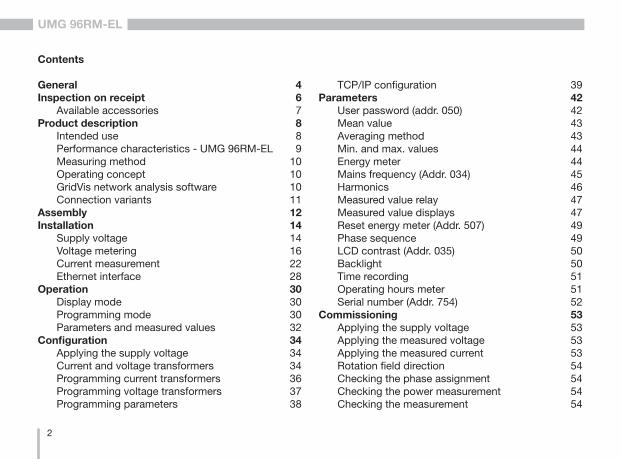
Contents
General 4Inspection on receipt 6
Available accessories 7Product description 8
Intended use 8Performance characteristics - UMG 96RM-EL 9Measuring method 10Operating concept 10GridVis network analysis software 10Connection variants 11
Assembly 12Installation 14
Supply voltage 14Voltage metering 16Current measurement 22Ethernet interface 28
Operation 30Display mode 30Programming mode 30Parameters and measured values 32
Configuration 34Applying the supply voltage 34Current and voltage transformers 34Programming current transformers 36Programming voltage transformers 37Programming parameters 38
TCP/IP configuration 39Parameters 42
User password (addr. 050) 42Mean value 43Averaging method 43Min. and max. values 44Energy meter 44Mains frequency (Addr. 034) 45Harmonics 46Measured value relay 47Measured value displays 47Reset energy meter (Addr. 507) 49Phase sequence 49LCD contrast (Addr. 035) 50Backlight 50Time recording 51Operating hours meter 51Serial number (Addr. 754) 52
Commissioning 53Applying the supply voltage 53Applying the measured voltage 53Applying the measured current 53Rotation field direction 54Checking the phase assignment 54Checking the power measurement 54Checking the measurement 54
3
UMG 96RM-EL
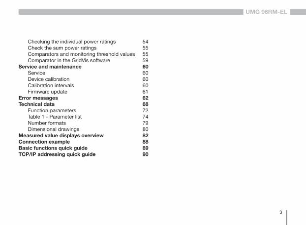
Checking the individual power ratings 54Check the sum power ratings 55Comparators and monitoring threshold values 55Comparator in the GridVis software 59
Service and maintenance 60Service 60Device calibration 60Calibration intervals 60Firmware update 61
Error messages 62Technical data 68
Function parameters 72Table 1 - Parameter list 74Number formats 79Dimensional drawings 80
Measured value displays overview 82Connection example 88Basic functions quick guide 89TCP/IP addressing quick guide 90

4
UMG 96RM-EL
Comments on the operating manual
We welcome your comments. In the event that anything in this operating manual seems unclear, please let us know and send us an EMAIL to: [email protected]
Meaning of the symbols
The following pictograms are used in the operating ma-nual at hand:
General
Copyright
This operating manual is subject to the legal require-ments for copyright protection and may not be, either in whole or in part, photocopied, reprinted, or reprodu-ced by mechanical or electronic means, or in any other manner be duplicated or redistributed without the legally binding, written agreement of
Janitza electronics GmbH, Vor dem Polstück 1,D 35633 Lahnau, Germany.
Trademarks
All trademarks and their resulting rights belong to the re-spective holders of these rights.
Disclaimer
Janitza electronics GmbH takes no responsibility for er-rors or defects within this operating manual and takes no responsibility for keeping the contents of this operating manual up to date.
c Dangerous voltage! Danger to life or risk of serious injury. Dis-connect system and device from power supply before beginning work.
m Caution!Please fo l low the documentat ion. This symbol warns of possible dangers that can arise during installation, commis-sioning and use.
C Note!
5
UMG 96RM-EL
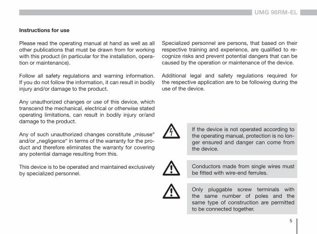
Instructions for use
Please read the operating manual at hand as well as all other publications that must be drawn from for working with this product (in particular for the installation, opera-tion or maintenance).
Follow all safety regulations and warning information. If you do not follow the information, it can result in bodily injury and/or damage to the product.
Any unauthorized changes or use of this device, which transcend the mechanical, electrical or otherwise stated operating limitations, can result in bodily injury or/and damage to the product.
Any of such unauthorized changes constitute „misuse“ and/or „negligence“ in terms of the warranty for the pro-duct and therefore eliminates the warranty for covering any potential damage resulting from this.
This device is to be operated and maintained exclusively by specialized personnel.
c If the device is not operated according to the operating manual, protection is no lon-ger ensured and danger can come from the device.
m Conductors made from single wires must be fitted with wire-end ferrules.
m Only pluggable screw terminals with the same number of poles and the same type of construction are permitted to be connected together.
Specialized personnel are persons, that based on their respective training and experience, are qualified to re-cognize risks and prevent potential dangers that can be caused by the operation or maintenance of the device.
Additional legal and safety regulations required for the respective application are to be following during the use of the device.
6
UMG 96RM-EL
Inspection on receipt
The prerequisites of faultless, safe operation of this de-vice are proper transport and proper storage, set-up and assembly, as well as careful operation and maintenance. If it can be assumed that risk-free operation is no longer possible, the unit must be immediately put out of opera-tion and secured against being put back into operation again.The packing and unpacking must be carried out with the customary care without the use of force and only using suitable tools. The devices should be visually che-cked for flawless mechanical condition. It can be assumed that risk-free operation is no longer possible if the device, for example,
• has visible damage • no longer works despite the mains power supply
being intact• has been exposed to long-term adverse conditions
(e.g. storage outside the permissible climate limits wi-thout being adapted to the room climate, condensa-tion etc.) or rough handling during transportation (e.g. fall from a height, even if there is no visible external damage etc.)
• Please check the delivered items for completeness before you start installing the device.
C All screw-type terminals included in delivery are attached to the device.
Concerning these operating instructions
These operating instructions are a part of the product.• Read the operating instructions before using the de-
vice.• Keep the operating instructions throughout the enti-
re service life of the product and have them readily available for reference.
• Pass the operating instructions on to each subse-quent owner or user of the product.
7
UMG 96RM-EL
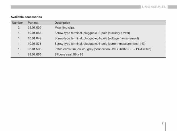
Number Part no. Description
2 29.01.036 Mounting clips
1 10.01.855 Screw-type terminal, pluggable, 2-pole (auxiliary power)
1 10.01.849 Screw-type terminal, pluggable, 4-pole (voltage measurement)
1 10.01.871 Screw-type terminal, pluggable, 6-pole (current measurement I1-I3)
1 08.01.505 Patch cable 2m, coiled, grey (connection UMG 96RM-EL — PC/Switch)
1 29.01.065 Silicone seal, 96 x 96
Available accessories

8
UMG 96RM-EL
Product description
Intended useThe UMG 96RM-EL is provided for the measurement and calculation of electrical parameters such as voltage, current, power, energy, harmonics, etc. for building installations, to distributors, circuit breakers and busbar trunking systems. The UMG 96RM-EL is suitable for installation in permanent, weatherproof switchboards. Conducting switchboards must be earthed. It can be mounted in any position.
Measurement voltages and measurement currents must originate from the same grid.The measurement results can be displayed and can be read and processed over the Ethernet interface.
The voltage measurement inputs are designed for measuring in low voltage grids in which nominal voltages up to 300V phase can occur in countercurrent with ground and overvoltages of overvoltage category III.
The UMG 96RM-EL current measurement inputs are connected via external ../1A or ../5A current transformers.
Measurements in medium and high voltage systems generally use current and voltage transformers.
The UMG 96RM-EL can be used in residential and industrial areas.
Device characteristics• Installation depth: 45 mm• Supply voltage:
Option 230V: 90V - 277V (50/60Hz) or DC 90V - 250V; 300V CATIII Option 24V: 24 - 90V AC / DC; 150V CATIII
• Frequency range: 45-65 Hz
Device functions• 3 voltage measurements, 300 V• 3 current measurements
(via current transformer) • Ethernet interface
9
UMG 96RM-EL
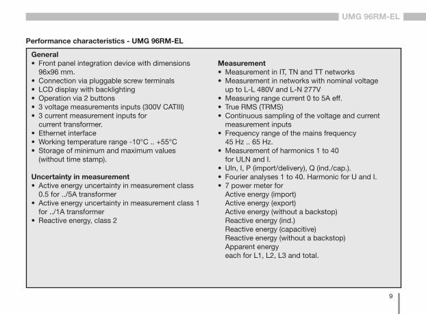
Performance characteristics - UMG 96RM-EL
General• Front panel integration device with dimensions 96x96 mm.• Connection via pluggable screw terminals• LCD display with backlighting• Operation via 2 buttons• 3 voltage measurements inputs (300V CATIII)• 3 current measurement inputs for current transformer.• Ethernet interface• Working temperature range -10°C .. +55°C• Storage of minimum and maximum values (without time stamp).
Uncertainty in measurement• Active energy uncertainty in measurement class 0.5 for ../5A transformer• Active energy uncertainty in measurement class 1 for ../1A transformer• Reactive energy, class 2
Measurement• Measurement in IT, TN and TT networks• Measurement in networks with nominal voltage up to L-L 480V and L-N 277V• Measuring range current 0 to 5A eff.• True RMS (TRMS)• Continuous sampling of the voltage and current measurement inputs• Frequency range of the mains frequency 45 Hz .. 65 Hz.• Measurement of harmonics 1 to 40 for ULN and I.• Uln, I, P (import/delivery), Q (ind./cap.).• Fourier analyses 1 to 40. Harmonic for U and I.• 7 power meter for Active energy (import) Active energy (export) Active energy (without a backstop) Reactive energy (ind.) Reactive energy (capacitive) Reactive energy (without a backstop) Apparent energy each for L1, L2, L3 and total.
10
UMG 96RM-EL
Measuring method
The UMG 96RM-EL measures uninterrupted and calculates all root mean squares over a 10/12-period interval (200ms). The UMG 96RM-EL measures the true root mean square (TRMS) of the voltages and currents applied to the measuring inputs.
Operating concept
There are several ways to program the UMG 96RM-EL and retrieve measured values.
• Directly on the device using two buttons.• Via the programming software of the GridVis.
These operating instructions only describe the operation of the UMG 96RM-EL using the 2 buttons.The programming software of the GridVis has its own “online help”.
GridVis network analysis software
The UMG 96RM-EL can be programmed and read with the GridVis network analysis software (Download: www.janitza.com). For this a PC must be connected to the UMG 96RM-EL via Ethernet.
Characteristics of GridVis
• Programming the UMG 96RM-EL• Graphic representation of measured values
11
UMG 96RM-EL
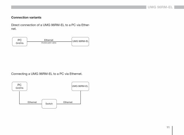
Connection variants
Direct connection of a UMG 96RM-EL to a PC via Ether-net.
Connecting a UMG 96RM-EL to a PC via Ethernet.
(gedrehtes Patchkabel)UMG 96RM-EL
(gedrehtes Patchkabel)
UMG 96RM-EL
Switch
(Twisted patch cable)
12
UMG 96RM-EL
Assembly
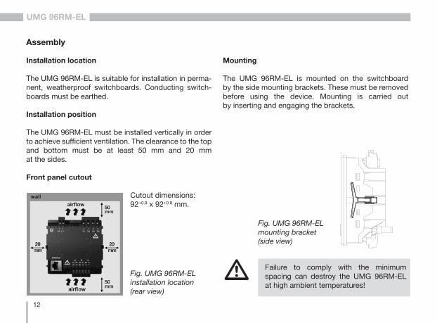
Installation location
The UMG 96RM-EL is suitable for installation in perma-nent, weatherproof switchboards. Conducting switch-boards must be earthed.
Installation position
The UMG 96RM-EL must be installed vertically in order to achieve sufficient ventilation. The clearance to the top and bottom must be at least 50 mm and 20 mm at the sides.
Front panel cutout
Cutout dimensions: 92+0.8 x 92+0.8 mm.
m Failure to comply with the minimum spacing can destroy the UMG 96RM-EL at high ambient temperatures!
Fig. UMG 96RM-EL installation location (rear view)
Mounting
The UMG 96RM-EL is mounted on the switchboard by the side mounting brackets. These must be removed before using the device. Mounting is carried out by inserting and engaging the brackets.
Fig. UMG 96RM-EL mounting bracket (side view)

13
UMG 96RM-EL
14
UMG 96RM-EL
Installation
Supply voltage
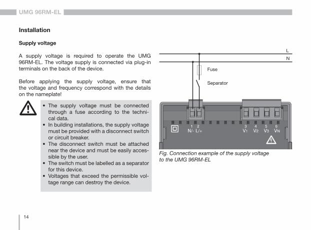
A supply voltage is required to operate the UMG 96RM-EL. The voltage supply is connected via plug-in terminals on the back of the device.
Before applying the supply voltage, ensure that the voltage and frequency correspond with the details on the nameplate!
Fig. Connection example of the supply voltage to the UMG 96RM-EL
Separator
Fuse
N
L
m • The supply voltage must be connected through a fuse according to the techni-cal data.
• In building installations, the supply voltage must be provided with a disconnect switch or circuit breaker.
• The disconnect switch must be attached near the device and must be easily acces-sible by the user.
• The switch must be labelled as a separator for this device.
• Voltages that exceed the permissible vol-tage range can destroy the device.

15
UMG 96RM-EL
16
UMG 96RM-EL
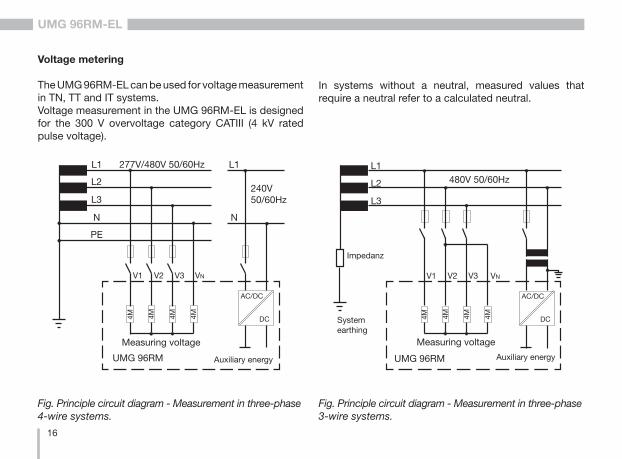
Voltage metering
The UMG 96RM-EL can be used for voltage measurement in TN, TT and IT systems.Voltage measurement in the UMG 96RM-EL is designed for the 300 V overvoltage category CATIII (4 kV rated pulse voltage).
Fig. Principle circuit diagram - Measurement in three-phase 4-wire systems.
Fig. Principle circuit diagram - Measurement in three-phase 3-wire systems.
In systems without a neutral, measured values that require a neutral refer to a calculated neutral.
480V 50/60Hz
DC
AC/DC
L2
L3
Auxiliary energy
Measuring voltage
4M 4M 4M 4M
V1 V3V2
System earthing
Impedanz
L1
VN
UMG 96RM
DC
AC/DC
PE
277V/480V 50/60Hz
L2
L3
N
L1
Auxiliary energy
Measuring voltage
4M 4M 4M 4M
V1 V3V2 VN
UMG 96RM
N
L1
240V 50/60Hz
17
UMG 96RM-EL
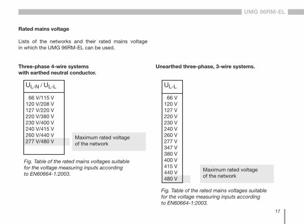
Rated mains voltage
Lists of the networks and their rated mains voltage in which the UMG 96RM-EL can be used.
Three-phase 4-wire systems with earthed neutral conductor.
Maximum rated voltage of the network
UL-N / UL-L
66 V/115 V120 V/208 V127 V/220 V220 V/380 V230 V/400 V240 V/415 V260 V/440 V277 V/480 V
Fig. Table of the rated mains voltages suitable for the voltage measuring inputs according to EN60664-1:2003.
Unearthed three-phase, 3-wire systems.
Fig. Table of the rated mains voltages suitable for the voltage measuring inputs according to EN60664-1:2003.
Maximum rated voltage of the network
UL-L
66 V 120 V 127 V 220 V 230 V 240 V 260 V 277 V 347 V380 V400 V415 V440 V480 V
18
UMG 96RM-EL
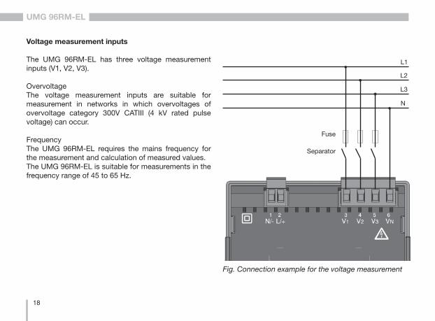
Voltage measurement inputs
The UMG 96RM-EL has three voltage measurement inputs (V1, V2, V3). OvervoltageThe voltage measurement inputs are suitable for measurement in networks in which overvoltages of overvoltage category 300V CATIII (4 kV rated pulse voltage) can occur.
FrequencyThe UMG 96RM-EL requires the mains frequency for the measurement and calculation of measured values. The UMG 96RM-EL is suitable for measurements in the frequency range of 45 to 65 Hz.
Fig. Connection example for the voltage measurement
Separator
Fuse
L2
L3
N
L1
19
UMG 96RM-EL
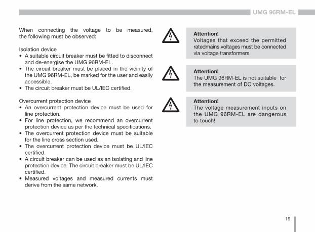
c Attention!Voltages that exceed the permitted ratedmains voltages must be connected via voltage transformers.
c Attention!The UMG 96RM-EL is not suitable for the measurement of DC voltages.
c Attention!The voltage measurement inputs on the UMG 96RM-EL are dangerous to touch!
When connecting the voltage to be measured, the following must be observed:
Isolation device• A suitable circuit breaker must be fitted to disconnect
and de-energise the UMG 96RM-EL.• The circuit breaker must be placed in the vicinity of
the UMG 96RM-EL, be marked for the user and easily accessible.
• The circuit breaker must be UL/IEC certified.
Overcurrent protection device• An overcurrent protection device must be used for
line protection.• For line protection, we recommend an overcurrent
protection device as per the technical specifications.• The overcurrent protection device must be suitable
for the line cross section used.• The overcurrent protection device must be UL/IEC
certified.• A circuit breaker can be used as an isolating and line
protection device. The circuit breaker must be UL/IEC certified.
• Measured voltages and measured currents must derive from the same network.
20
UMG 96RM-EL
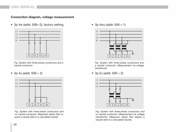
Connection diagram, voltage measurement
L1
L2
L3N
V1 V2 V3 VN
• 3p 4w (addr. 509= 0), factory setting
L1
L2
L3N
V1 V2 V3 VN
• 3p 4wu (addr. 509 = 1)
• 3p 4u (addr. 509 = 2)
L1
L2
L3
V1 V2 V3 VN
L1
L2
L3
V1 V2 V3 VN
• 3p 2u (addr. 509 = 5)
Fig. System with three-phase conductors and a neutral conductor.
Fig. System with three-phase conductors and a neutral conductor. Measurement via voltage transformer.
Fig. System with three-phase conductors and no neutral conductor. Measured values that re-quire a neutral refer to a calculated neutral.
Fig. System with three-phase conductors and no neutral conductor. Measurement via voltage transformer. Measured values that require a neutral refer to a calculated neutral.
21
UMG 96RM-EL
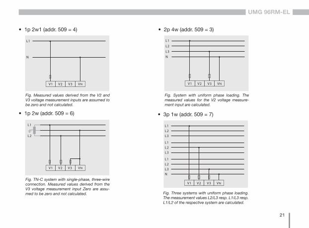
• 1p 2w (addr. 509 = 6)
L1
L2
V1 V2 V3 VN
L1
L2
L3N
V1 V2 V3 VN
• 2p 4w (addr. 509 = 3)
L1
N
V1 V2 V3 VN
• 1p 2w1 (addr. 509 = 4)
Fig. TN-C system with single-phase, three-wire connection. Measured values derived from the V3 voltage measurement input Zero are assu-med to be zero and not calculated.
Fig. Measured values derived from the V2 and V3 voltage measurement inputs are assumed to be zero and not calculated.
Fig. System with uniform phase loading. The measured values for the V2 voltage measure-ment input are calculated.
L1L2L3
L1L2L3
L1L2L3
V1 V2 V3 VN
N
• 3p 1w (addr. 509 = 7)
Fig. Three systems with uniform phase loading. The measurement values L2/L3 resp. L1/L3 resp.L1/L2 of the respective system are calculated.
22
UMG 96RM-EL
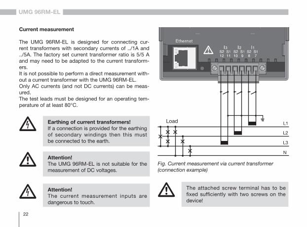
Current measurement
The UMG 96RM-EL is designed for connecting cur-rent transformers with secondary currents of ../1A and ../5A. The factory set current transformer ratio is 5/5 A and may need to be adapted to the current transform-ers. It is not possible to perform a direct measurement with-out a current transformer with the UMG 96RM-EL. Only AC currents (and not DC currents) can be meas-ured.The test leads must be designed for an operating tem-perature of at least 80°C.
c Attention!The current measurement inputs are dangerous to touch.
m Attention! The UMG 96RM-EL is not suitable for the measurement of DC voltages.
c Earthing of current transformers!If a connection is provided for the earthing of secondary windings then this must be connected to the earth.
L2
L3
N
L1
Fig. Current measurement via current transformer (connection example)
Load
m The attached screw terminal has to be fixed sufficiently with two screws on the device!
23
UMG 96RM-EL
Direction of the current
The current direction can be individually corrected on the device or via the serial interfaces for each phase.
In the case of incorrect connection, the current trans-former does not need to be subsequently reconnected.
c Current transformer connections!The secondary connection of the current transformer must be short-circuited on this before the current feed to the UMG 96RM-EL is disconnected!If a test switch, which automatically short-circuits the secondary wires of the current transformer, is available then it is sufficient to set this to the „Test“ position insofar as the short-circuiting device has been che-cked beforehand.
c Open-circuit current transformers!High voltage spikes that are dangerous to touch can occur on current transformers that are driven with open-circuit secondary windings!With “safe open-circuit current transform-ers” the winding insulation is rated such that the current transformer can be driven open. However, even these current trans-formers are dangerous to touch when they are driven open-circuit.
c Earthing of current transformers!If a connection is provided for the earthing of secondary windings then this must be connected to the earth.
24
UMG 96RM-EL
Connection diagram, current measurement
L1
L2
L3N
I1 I2 I3
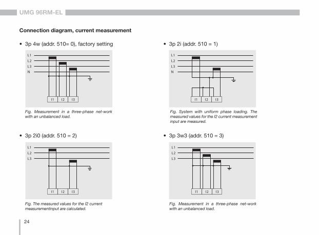
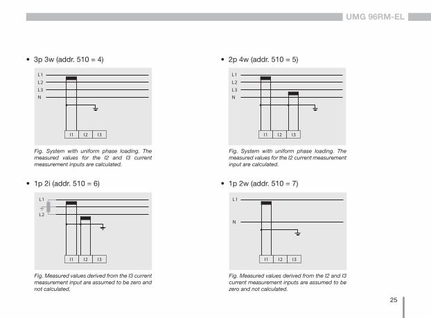
• 3p 4w (addr. 510= 0), factory setting • 3p 2i (addr. 510 = 1)
L1
L2
L3N
I1 I2 I3
L1
L2
L3
I1 I2 I3
• 3p 2i0 (addr. 510 = 2)
L1
L2
L3
I1 I2 I3
• 3p 3w3 (addr. 510 = 3)
Fig. Measurement in a three-phase net-work with an unbalanced load.
Fig. The measured values for the I2 current measurementinput are calculated.
Fig. System with uniform phase loading. The measured values for the I2 current measurement input are measured.
Fig. Measurement in a three-phase net-work with an unbalanced load.
25
UMG 96RM-EL
• 1p 2i (addr. 510 = 6)
I1 I2 I3
L1
L2
L1
L2
L3N
I1 I2 I3
• 3p 3w (addr. 510 = 4)
• 1p 2w (addr. 510 = 7)
L1
N
I1 I2 I3
L1
L2
L3N
I1 I2 I3
• 2p 4w (addr. 510 = 5)
Fig. Measured values derived from the I3 current measurement input are assumed to be zero and not calculated.
Fig. Measured values derived from the I2 and I3 current measurement inputs are assumed to be zero and not calculated.
Fig. System with uniform phase loading. The measured values for the I2 current measurement input are calculated.
Fig. System with uniform phase loading. The measured values for the I2 and I3 current measurement inputs are calculated.
26
UMG 96RM-EL
Connection diagram, current measurement
L1L2L3
I1 I2 I3
L1L2L3
L1L2L3
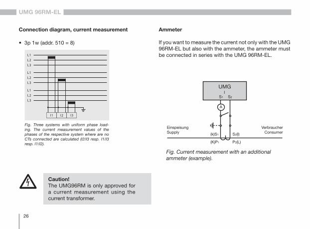
• 3p 1w (addr. 510 = 8)
Fig. Three systems with uniform phase load-ing. The current measurement values of the phases of the respective system where are no CTs connected are calculated (I2/I3 resp. I1/I3 resp. I1/I2).
Ammeter
If you want to measure the current not only with the UMG 96RM-EL but also with the ammeter, the ammeter must be connected in series with the UMG 96RM-EL.
Fig. Current measurement with an additional ammeter (example).
UMG
S2
IS1
EinspeisungSupply
VerbraucherConsumer
A
(k)S1 S2(l)
P2(L)(K)P1
c Caution! The UMG96RM is only approved for a current measurement using the current transformer.

27
UMG 96RM-EL
Total current measurement
If the current measurement takes place via two current transformers, the total transformer ratio of the current transformer must be programmed in the UMG 96RM-EL.
Example: The current measurement takes place via two current transformers. Both current transformers have a transformer ratio of 1000/5 A. The total measurement is performed with a 5+5/5 A total current transformer.
The UMG 96RM-EL must then be set as follows:Primary current: 1000 A + 1000 A = 2000 ASecondary current: 5 A
Fig. Current measurement via a total current transformer (example).
UMG
S2
IS1
P1 P2
Einspeisung 1Supply 1
Einspeisung 2Supply 2
1P1
1P2
(K)
(L)(k)(l)
1S2
1S1
1S1 1S2 2S1 2S2
2S1
2S2
(k)(l)
(K)(L)
2P1
2P2
Verbraucher AConsumer A
Verbraucher BConsumer B
28
UMG 96RM-EL
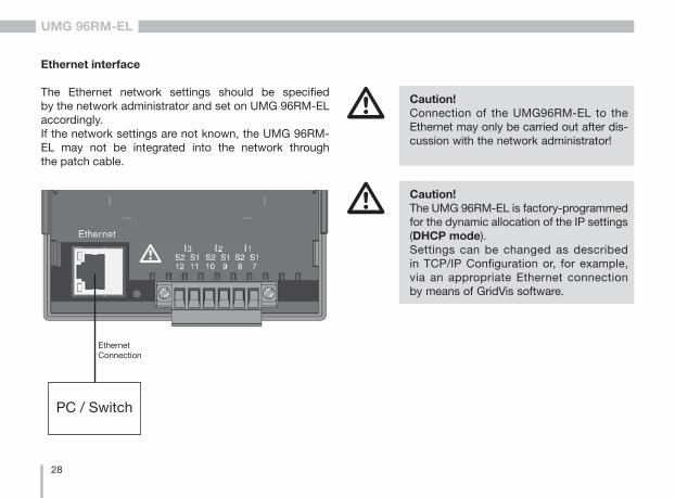
Ethernet interface
The Ethernet network settings should be specified by the network administrator and set on UMG 96RM-EL accordingly. If the network settings are not known, the UMG 96RM-EL may not be integrated into the network through the patch cable.
m Caution! Connection of the UMG96RM-EL to the Ethernet may only be carried out after dis-cussion with the network administrator!
PC / Switch
EthernetConnection
m Caution! The UMG 96RM-EL is factory-programmed for the dynamic allocation of the IP settings (DHCP mode).Settings can be changed as described in TCP/IP Configuration or, for example, via an appropriate Ethernet connection by means of GridVis software.

29
UMG 96RM-EL
30
UMG 96RM-EL
Operation
The UMG 96RM-EL is operated via buttons 1 and 2 with the following functions:• briefly pressing button 1 and 2:
next step (+1)• pressing and holding button 1 and 2:
previous step (-1)Measured values and programming data are displayed on an LCD display.
There are display and programming modes. You can avoid an unintentional change of programming data by entering a password.
Display mode
In display mode, you can scroll through the programmed measured values by pressing buttons 1 and 2. When the device is delivered, all measured value indications of profile 1 can be retrieved. For each measured value, up to three measured values are indicated. The measured value rotation can display selected measured value indi-cations one after the other with a selectable changing time.
Programming mode
You can view and change the necessary settings of the UMG 96RM-EL in programming mode. Press but-ton 1 and 2 simultaneously for about 1 second to switch to programming mode after entering the password. If no password is programmed, you get directly to the pro-gramming mode menu. Programming mode is marked by the text „PRG“ on the display.
Press button 2 to switch between the following menus:
- Current transformer, - Voltage transformer, - Parameter list,- TCP/IP device address,- Subnet mask,- Gateway address,- Dynamic TCP/IP addressing (in/out).
If no button was pressed for about 60 seconds when you are in programming mode, or button 1 and 2 are pressed simultaneously for about 1 second, the UMG 96RM-EL will switch back to display mode.
31
UMG 96RM-EL
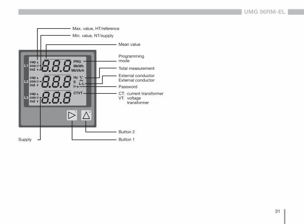
Button 1
Button 2
Supply
Mean value
CT: current transformerVT: voltage transformer
Password
External conductorExternal conductor
Total measurement
Programming mode
Min. value, NT/supply
Max. value, HT/reference
32
UMG 96RM-EL
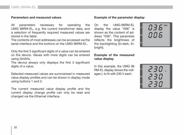
Parameters and measured values
All parameters necessary for operating the UMG 96RM-EL, e.g. the current transformer data, and a selection of frequently required measured values are stored in the table.The contents of most addresses can be accessed via the serial interface and the buttons on the UMG 96RM-EL.
Only the first 3 significant digits of a value can be entered on the device. Values with more digits can be entered using GridVis.The device always only displays the first 3 significant digits of a value.
Selected measured values are summarised in measured value display profiles and can be shown in display mode using buttons 1 and 2.
The current measured value display profile and the current display change profile can only be read and changed via the Ethernet interface.
Example of the parameter display
On the UMG 96RM-EL display the value “006” is shown as the content of ad-dress “036”. This parameter reflects the brightness of the backlighting (0=dark, 9= bright).
Example of the measured value display
In this example, the UMG 96 RM-EL display shows the volt-ages L to N with 230 V each.
33
UMG 96RM-EL
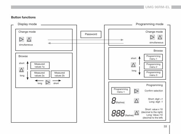
Button functions
Password
Display mode
simultaneous
Change mode
Browse
long
short Measured values 1a
Measured values 2a
Measured values 2b
long short
Programming mode
simultaneous
Change mode
Browse
long
shortProgramming
menu 1
Programmingmenu 2
Programmingmenu 3
ProgrammingProgramming
menu 1 Confirm selection
(flashes)
Short: digit +1Long: digit -1
(flashes)
Short: value x 10(decimal to the right)
Long: Value /10(decimal to the left)
34
UMG 96RM-EL
Configuration
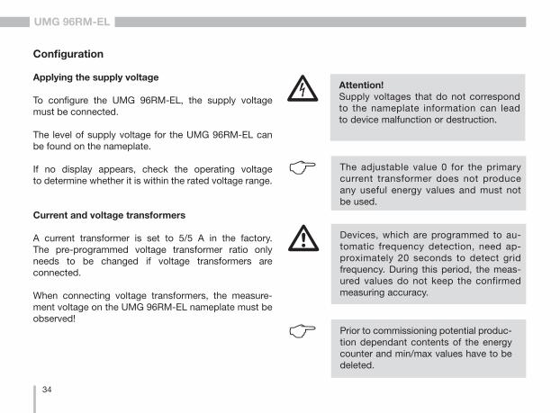
Applying the supply voltage
To configure the UMG 96RM-EL, the supply voltage must be connected.
The level of supply voltage for the UMG 96RM-EL can be found on the nameplate.
If no display appears, check the operating voltage to determine whether it is within the rated voltage range.
Current and voltage transformers
A current transformer is set to 5/5 A in the factory. The pre-programmed voltage transformer ratio only needs to be changed if voltage transformers are connected.
When connecting voltage transformers, the measure-ment voltage on the UMG 96RM-EL nameplate must be observed!
c Attention!Supply voltages that do not correspond to the nameplate information can lead to device malfunction or destruction.
C The adjustable value 0 for the primary current transformer does not produce any useful energy values and must not be used.
m Devices, which are programmed to au-tomatic frequency detection, need ap-proximately 20 seconds to detect grid frequency. During this period, the meas-ured values do not keep the confirmed measuring accuracy.
C Prior to commissioning potential produc-tion dependant contents of the energy counter and min/max values have to be deleted.
35
UMG 96RM-EL
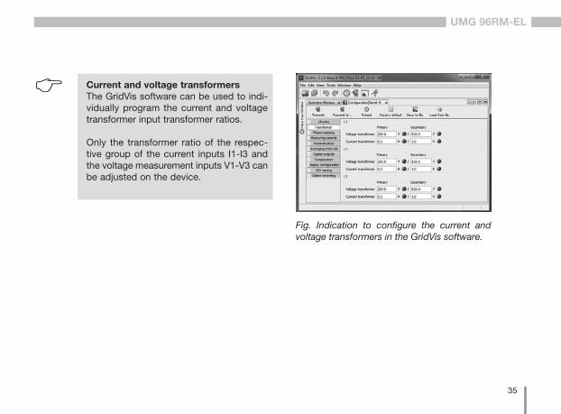
C Current and voltage transformersThe GridVis software can be used to indi-vidually program the current and voltage transformer input transformer ratios.
Only the transformer ratio of the respec-tive group of the current inputs I1-I3 and the voltage measurement inputs V1-V3 can be adjusted on the device.
Fig. Indication to configure the current and voltage transformers in the GridVis software.
36
UMG 96RM-EL
Programming current transformers
Switching to programming mode• Simultaneously press buttons 1 and 2 in order
to switch to programming mode. If a user password was programmed, the password request will appear with “000”. The first digit of the user password flashes and can be changed with button 2. The next digit is selected by pressing button 2 and will begin flashing. If the correct combination was entered or if no user password was programmed, the device will enter pro-gramming mode.
• The symbols for the programming mode (PRG) and for the current transformer (CT) appear.
• Confirm the selection with button 1. • The first digit of the input area for the primary current
starts flashing.
Current transformer primary current input• Change the flashing digit with button 2. • Select the next digit to be changed with button 1.
The selected digit to be changed starts flashing. If the entire number is flashing, the decimal point can be moved with button 2.
Current transformer secondary current input
• Only 1 A or 5 A can be set as the secondary current. • Select the secondary current with button 1.• Change the flashing digit with button 2.
Leaving programming mode• Simultaneously press buttons 1 and 2 to exit the pro-
gramming mode.
37
UMG 96RM-EL
Current transformer symbol
Units display
Current transformer, primary
Programming mode
Current transformer, secondary
Units display
Voltage transformer, primary
Programming mode
Voltage transformer, secondary
Voltage transformer, symbol
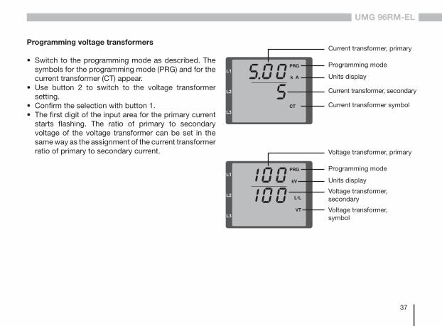
Programming voltage transformers
• Switch to the programming mode as described. The symbols for the programming mode (PRG) and for the current transformer (CT) appear.
• Use button 2 to switch to the voltage transformer setting.
• Confirm the selection with button 1. • The first digit of the input area for the primary current
starts flashing. The ratio of primary to secondary voltage of the voltage transformer can be set in the same way as the assignment of the current transformer ratio of primary to secondary current.
38
UMG 96RM-EL
(Seitenbezug)
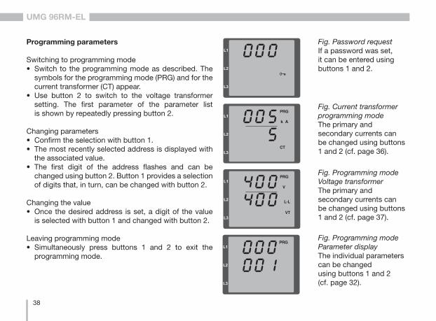
Fig. Password requestIf a password was set, it can be entered using buttons 1 and 2.
Fig. Current transformer programming modeThe primary and secondary currents can be changed using buttons 1 and 2 (cf. page 36).
Fig. Programming modeVoltage transformerThe primary and secondary currents can be changed using buttons 1 and 2 (cf. page 37).
Programming parameters
Switching to programming mode• Switch to the programming mode as described. The
symbols for the programming mode (PRG) and for the current transformer (CT) appear.
• Use button 2 to switch to the voltage transformer setting. The first parameter of the parameter list is shown by repeatedly pressing button 2.
Changing parameters• Confirm the selection with button 1.• The most recently selected address is displayed with
the associated value.• The first digit of the address flashes and can be
changed using button 2. Button 1 provides a selection of digits that, in turn, can be changed with button 2.
Changing the value• Once the desired address is set, a digit of the value
is selected with button 1 and changed with button 2.
Leaving programming mode• Simultaneously press buttons 1 and 2 to exit the
programming mode.
Fig. Programming modeParameter displayThe individual parameters can be changed using buttons 1 and 2 (cf. page 32).
39
UMG 96RM-EL
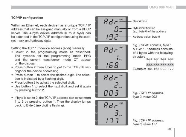
TCP/IP configuration
Within an Ethernet, each device has a unique TCP / IP address that can be assigned manually or from a DHCP server. The 4-byte device address (0 to 3 byte) can be extended in the TCP / IP configuration using the sub-net mask and gateway data.
Setting the TCP / IP device address (addr) manually• Select in the programming mode as described.
The symbols for the programming mode PRG and the current transformer mode CT appear on the display.
• Press button 2 three times to get to the TCP / IP set-tings for the device addressing.
• Press button 1 to select the desired digit. The selec-tion is indicated by a flashing digit.
• Press button 2 to adjust the selected digit.• Use button 1 to select the next digit and set it again
by pressing button 2.
• If byte is set to 0, the TCP / IP address can be set from 1 to 3 by pressing button 1. Then the display jumps back to Byte 0 (no digit is flashing).
Description
Byte identification (e.g. byte 0) of the address
Address value, byte 0
Fig. TCP/IP address, byte 1A TCP / IP address consists of 4 bytes with the following structure:
xxx.xxx.xxx.xxx
Byte 1Byte 0 Byte 2 Byte 3
Fig. TCP / IP address, byte 2, value 003
Fig. TCP / IP address, byte 3, value 177
192.168.003.177Example:
40
UMG 96RM-EL
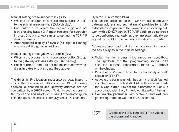
Manual setting of the subnet mask (SUb)• When in the programming mode, press button 2 to get
to the subnet mask settings (SUb display).• Use button 1 to select the desired digit and set
it by pressing button 2. Repeat this step for each digit in bytes 0 to 3 in a way similar to setting the TCP / IP device address.
• After repeated display of byte 0 (no digit is flashing) one can set the gateway address.
Manual setting of the gateway address (GAt)• When in the programming mode, press button 2 to get
to the gateway address settings (GAt display).• Press buttons 1 and 2 to set the desired gateway ad-
dress in bytes 0 to 3 as described above.
The dynamic IP allocation must also be deactivated to ensure that the manual settings of the TCP / IP device address, subnet mask and gateway address are not overwritten by a DHCP server. To do so set the parame-ter „dyn IP“ to a value of 0 or 3 (see „IP mode configura-tion“ table) as described under „Dynamic IP allocation“.
Dynamic IP allocation (dyn)The dynamic allocation of the TCP / IP settings (device/gateway address and subnet mask) provides for a fully automated integration of the device into an existing net-work with a DHCP server. TCP / IP settings do not need to be configured manually as they are automatically as-signed by the DHCP server when the device is started.
Addresses are read out in the programming mode the same way as in the manual settings.
• Switch to the programming mode as described. The symbols for the programming mode PRG and the current transformer mode CT appear on the display.
• Press button 2 several times to display the dynamic IP allocation (dYn IP).
• Activate the parameter with button 1 (1st digit flashes) and then select the last digit (digit flashes) with but-ton 1. Use button 2 to set the parameter to 2 or 5 in accordance with the „IP mode configuration“ table).
• Confirm the parameter with button 1 and exit pro-gramming mode or wait for ca. 60 seconds.
C Changes will only take effect after you exit the programming mode.
41
UMG 96RM-EL
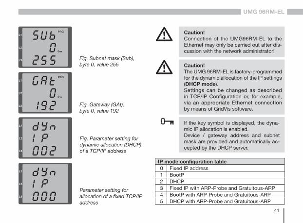
If the key symbol is displayed, the dyna-mic IP allocation is enabled. Device / gateway address and subnet mask are provided and automatically ac-cepted by the DHCP server.
Fig. Gateway (GAt), byte 0, value 192
Fig. Subnet mask (Sub), byte 0, value 255
m Caution! Connection of the UMG96RM-EL to the Ethernet may only be carried out after dis-cussion with the network administrator!
m Caution! The UMG 96RM-EL is factory-programmed for the dynamic allocation of the IP settings (DHCP mode).Settings can be changed as described in TCP/IP Configuration or, for example, via an appropriate Ethernet connection by means of GridVis software.
Fig. Parameter setting for dynamic allocation (DHCP) of a TCP/IP address
Parameter setting for allocation of a fixed TCP/IP address
IP mode configuration table0 Fixed IP address1 BootP2 DHCP3 Fixed IP with ARP-Probe and Gratuitous-ARP4 BootP with ARP-Probe and Gratuitous-ARP5 DHCP with ARP-Probe and Gratuitous-ARP

42
UMG 96RM-EL
Parameters
User password (addr. 050)
A user password can be programmed in order to impede any accidental change to programming data. A switch to the next programming menu can only be made after entering the correct user password. No user password is specified in the factory. In this case, the password menu is skipped and the current transformer menu is reached directly.
If a user password was programmed, the password menu will appear with the display “000”. The first digit of the user password flashes and can be changed with button 2. The next digit is selected by pressing button 1 and will begin flashing.The programming menu for the current transformer can only be accessed after entering the correct number combination.
Forgotten password
If you have forgotten the password, the password can only be cleared by using the GridVis PC software.To do this, connect the UMG 96RM-EL to the PC via a suitable interface. More information can be found in the help section of GridVis.
43
UMG 96RM-EL
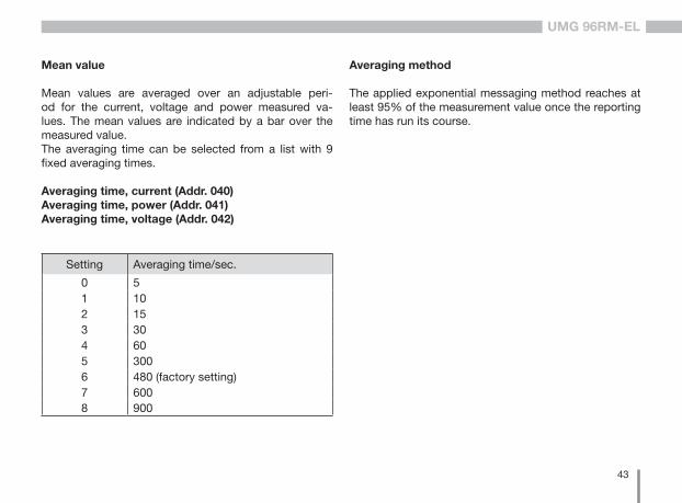
Averaging method
The applied exponential messaging method reaches at least 95% of the measurement value once the reporting time has run its course.
Mean value
Mean values are averaged over an adjustable peri-od for the current, voltage and power measured va-lues. The mean values are indicated by a bar over the measured value.The averaging time can be selected from a list with 9 fixed averaging times.
Averaging time, current (Addr. 040)Averaging time, power (Addr. 041)Averaging time, voltage (Addr. 042)
Setting Averaging time/sec.
0 51 102 153 304 605 3006 480 (factory setting)7 6008 900
44
UMG 96RM-EL
Min. and max. values
All measured values are measured and calculated dur-ing all 10/12 periods. Minimum and maximum values are determined for most measured values. The min. value is the smallest measured value deter-mined since the last deletion. The max. value is the high-est measured value determined since the last deletion. All minimum and maximum values are compared with the corresponding measured values and overwritten when exceeded or fallen short of.The minimum and maximum values are saved every 5 minutes in an EEPROM without date and time. Thus, the minimum and maximum values of the past 5 minutes may be lost due to an operating voltage failure.
Delete min. and max. values (Addr.506)
If "001" is set for address 506, all minimum and maxi-mum values can be deleted simultaneously. One exception is the maximum value of the mean cur-rent. Press and hold button 2 to delete the maximum value of the mean current in the display menu.
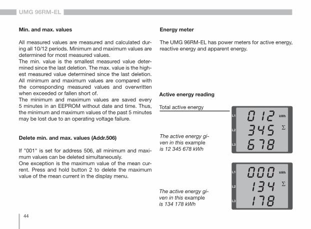
Energy meter
The UMG 96RM-EL has power meters for active energy, reactive energy and apparent energy.
Active energy reading
Total active energy
The active energy gi-ven in this example is 12 345 678 kWh
The active energy gi-ven in this example is 134 178 kWh
45
UMG 96RM-EL
Mains frequency (Addr. 034)
For automatic ascertainment of the mains frequency, an L1-N voltage larger than 10Veff must be applied to the voltage measurement input V1.
The sampling frequency is computed for the current and voltage inputs based on the mains frequency.
If the test voltage is missing, neither the network nor the sampling frequency can be computed. An acknowl-edgeable error message "500" will be displayed. Voltage, current and all resulting values are calculated and displayed based on the most recent frequen-cy measurement and/or possible power couplings. The measured values that have been determined can no longer guarantee the declared precision.
When another measurement of frequency can be car-ried out, the error message will automatically disappear in about 5 seconds after the voltage returns.
The error is not displayed when a fixed frequency is set.
Setting range: 0, 45 .. 650 = automatic frequency determination.The mains frequency is determined based on the measurement voltage.45..65 = fixed frequencyThe mains frequency is pre-selected as a fixed value.

46
UMG 96RM-EL
Harmonics
Harmonics are the integer multiple of a mains frequency. The voltage mains frequency for the UMG 96RM-EL must be in the range between 45 and 65 Hz. The calculated voltage and current harmonics refer to this mains frequency. Harmonics up to 40x the mains frequency are recorded.
The harmonics for currents are given in amperes and the harmonics for voltages are given in volts.
Fig. Display of the 15th harmonic of the current in the L3 phase (example).
Number of the harmonic
Phase L3
Current harmonic
Value
C Harmonics are not displayed in the factory default setting.
Total Harmonic Distortion (THD)
THD is the ratio of the root mean square value of harmonics to the root mean square value of the mains frequency.
Phase L3
Voltage
Value
Fig. Display of the total harmonic distortion of the voltage from the L3 phase (example).
Total Harmonic Distortion of the current (THDI):
Total Harmonic Distortion of the voltage (THDU):
47
UMG 96RM-EL
Measured value relay
All measured values are calculated every nine periods and can be recalled once per second on the measured value displays. Two methods are available for retrieving the measured value displays:
• The automatically changing display of selected measured values, referred to here as measured value relaying.
• Selection of a measured value display using buttons 1 and 2 from a preselected display profile.
Both methods are simultaneously available. Measured value relaying is active if at least one measured value display is programmed with a changeover time greater than 0 seconds. If a button is pressed, the measured value displays of the selected display profile can be browsed. If no button is pressed for about 60 seconds, the device switches to the measured value relay and the measured values from the selected display change profile of the programmed measured value displays are shown one after the other.
Changeover time (addr. 039)
Adjustment range: 0 .. 60 secondsIf 0 seconds are set, no changeover takes place between the measured value displays selected for the measured value relay.The changeover time applies for all display change profiles.
Display change profile (addr. 038)
Adjustment range: 0 .. 30 - Display changeover profile 1, by default.1 - Display changeover profile 2, by default.2 - Display changeover profile 3, by default.3 - Customised display changeover profile.
Measured value displays
After return of the power supply, the UMG 96RM-EL shows the first measured value panel from the current display profile. In order to keep the selection of meas-ured values to be displayed arranged in a clear manner, only one part of the available measured values is pre-programmed for recall in the measured value display by default. A different display profile can be selected if other measured values are required to be shown on the UMG 96RM-EL display.
48
UMG 96RM-EL
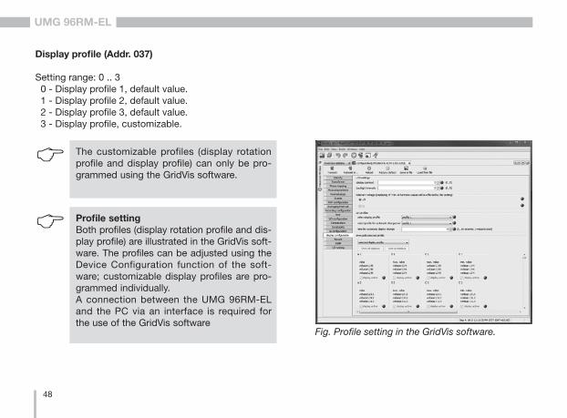
Display profile (Addr. 037)
Setting range: 0 .. 3 0 - Display profile 1, default value. 1 - Display profile 2, default value. 2 - Display profile 3, default value. 3 - Display profile, customizable.
C The customizable profiles (display rotation profile and display profile) can only be pro-grammed using the GridVis software.
C Profile settingBoth profiles (display rotation profile and dis-play profile) are illustrated in the GridVis soft-ware. The profiles can be adjusted using the Device Configuration function of the soft-ware; customizable display profiles are pro-grammed individually.A connection between the UMG 96RM-EL and the PC via an interface is required for the use of the GridVis software
Fig. Profile setting in the GridVis software.
49
UMG 96RM-EL
Reset energy meter (Addr. 507)
The real, apparent and reactive energy meters can only be reset simultaneously.
Set "001" for address 507 to reset the energy meter.
If you reset the energy meter, the data will be lost. To avoid data loss, you should read and save the measured values before de-letion using the GridVis software.
C
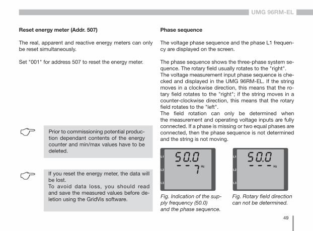
Phase sequence
The voltage phase sequence and the phase L1 frequen-cy are displayed on the screen. The phase sequence shows the three-phase system se-quence. The rotary field usually rotates to the "right".The voltage measurement input phase sequence is che-cked and displayed in the UMG 96RM-EL. If the string moves in a clockwise direction, this means that the ro-tary field rotates to the "right"; if the string moves in a counter-clockwise direction, this means that the rotary field rotates to the "left".The field rotation can only be determined when the measurement and operating voltage inputs are fully connected. If a phase is missing or two equal phases are connected, then the phase sequence is not determined and the string is not moving.
Fig. Indication of the sup-ply frequency (50.0) and the phase sequence.
Fig. Rotary field direction can not be determined.
C Prior to commissioning potential produc-tion dependant contents of the energy counter and min/max values have to be deleted.
50
UMG 96RM-EL
LCD contrast (Addr. 035)
The preferred view for the LCD display is from "below". The LCD display contrast can be adapted by the user. The contrast can be set stepwise in the range from 0 to 9.
0 = very bright 9 = very dark
Factory default setting: 5
Backlight
The LCD backlight allows the display to be read easily even in poor light. The brightness can be controlled by the user in stages from 0 to 9.
The UMG 96RM has two different types of backlight:
- the operation backlight- the standby backlight
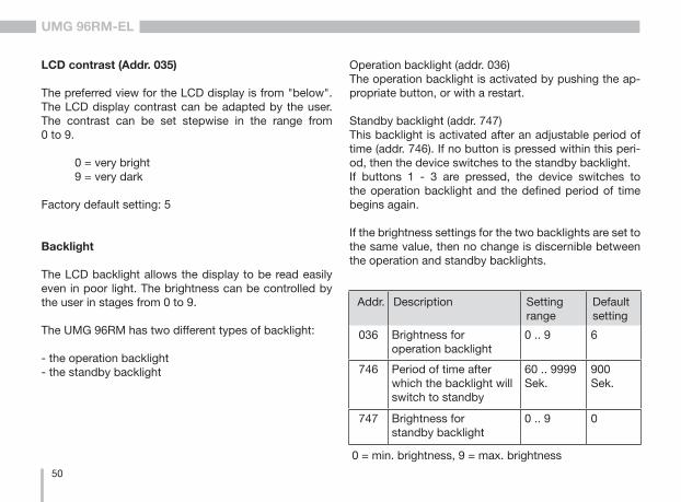
Operation backlight (addr. 036)The operation backlight is activated by pushing the ap-propriate button, or with a restart.
Standby backlight (addr. 747)This backlight is activated after an adjustable period of time (addr. 746). If no button is pressed within this peri-od, then the device switches to the standby backlight.If buttons 1 - 3 are pressed, the device switches to the operation backlight and the defined period of time begins again.
If the brightness settings for the two backlights are set to the same value, then no change is discernible between the operation and standby backlights.
Addr. Description Setting range
Default setting
036 Brightness foroperation backlight
0 .. 9 6
746 Period of time after which the backlight will switch to standby
60 .. 9999 Sek.
900 Sek.
747 Brightness forstandby backlight
0 .. 9 0
0 = min. brightness, 9 = max. brightness
51
UMG 96RM-EL
Time recording
The UMG 96RM-EL records the operating hours and the overall runtime of each comparator,
• where the operating period is measured and displayed in hours with a resolution of 0.1 h
• and the overall runtime of the comparators is displa-yed in seconds (when reaching 999999s is displayed in hours).
The periods are marked by the digits 1 to 6 for the measured value display enquiry:
keine = operating hours meter1 = Overall runtime, comparator 1A2 = Overall runtime, comparator 2A3 = Overall runtime, comparator 1B4 = Overall runtime, comparator 2B5 = Overall runtime, comparator 1C6 = Overall runtime, comparator 2C
In the measured value display, a maximum of 99999.9 h (= 11.4 years) can be displayed.
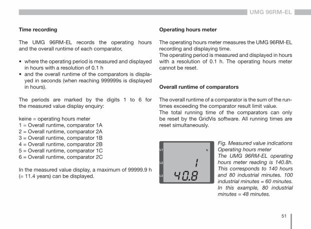
Fig. Measured value indications Operating hours meterThe UMG 96RM-EL operating hours meter reading is 140.8h. This corresponds to 140 hours and 80 industrial minutes. 100 industrial minutes = 60 minutes. In this example, 80 industrial minutes = 48 minutes.
Operating hours meter
The operating hours meter measures the UMG 96RM-EL recording and displaying time. The operating period is measured and displayed in hours with a resolution of 0.1 h. The operating hours meter cannot be reset.
Overall runtime of comparators
The overall runtime of a comparator is the sum of the run-times exceeding the comparator result limit value. The total running time of the comparators can only be reset by the GridVis software. All running times are reset simultaneously.
52
UMG 96RM-EL
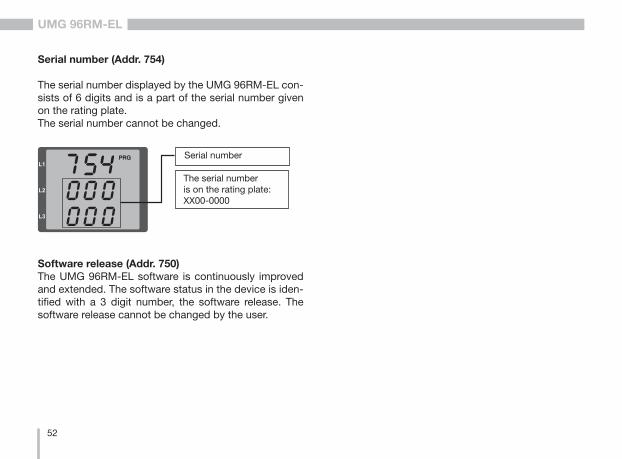
Serial number (Addr. 754)
The serial number displayed by the UMG 96RM-EL con-sists of 6 digits and is a part of the serial number given on the rating plate.The serial number cannot be changed.
Software release (Addr. 750)The UMG 96RM-EL software is continuously improved and extended. The software status in the device is iden-tified with a 3 digit number, the software release. The software release cannot be changed by the user.
Serial number
The serial number is on the rating plate: XX00-0000
53
UMG 96RM-EL
Commissioning
Applying the supply voltage
• The level of supply voltage for the UMG 96RM-EL can be found on the nameplate.
• After applying the supply voltage, the UMG 96RM-EL switches to the first measured value display.
• If no display appears, the supply voltage must be checked to determine whether it is in the rated voltage range.
Applying the measured voltage
• Voltage measurements in networks with rated voltages above 300V AC to ground must be connected to a voltage transformer.
• After the measured voltages are connected, the measured values for the L-N and L-L voltages displayed by the UMG 96RM-EL must match those at the voltage measurement input. m Attention!
Supply voltages that do not correspond to the nameplate information can lead to device malfunction or destruction.
m Attention! The UMG 96RM-EL is not suitable for the measurement of DC voltages.
Applying the measured current
The UMG 96RM-EL is designed for connecting ../1 A and ../5 A current transformers.Only AC currents and not DC currents can be measured via the current measurement inputs.Short circuit all current transformer outputs except for one. Compare the currents displayed on the UMG 96RM-EL with the applied current.The current displayed by the UMG 96RM-EL must match the input current, taking the current transformer ratio into consideration.In the short circuit current measurement inputs, the UMG 96RM-EL must show approx. zero amperes.
The factory-set current transformer ratio is 5/5 A and may need to be adapted to the current transformer used.
m Attention! Voltages and currents outside the permis-sible metering range can result in personal injury and damage to the device.
54
UMG 96RM-EL
Rotation field direction
Check the direction of the voltage rotation field on the measured value display of the UMG 96RM-EL. Usually there is a "clockwise" spinning rotation field.
Checking the phase assignment
The assignment of the phase conductor to the current transformer is correct if a current transformer is short circuited at the secondary terminals and the current shown by the UMG 96RM-EL in the corresponding phase sinks to 0A.
Checking the power measurement
Short circuit all current transformer outputs except for one and check the displayed power.The UMG 96RM-EL must only show one rating in the phase with the non-short-circuited current transformer input. If this does not apply, check the measured voltage connection and the measured current connection.
If the magnitude of the real power is correct but the sign of the real power is negative, this can be due to two causes:• The connections S1 (k) and S2 (I) on the current
transformer are inverted.• Active energy is being returned to the network.
Checking the measurement
If all voltage and current measurement inputs are correctly connected, the individual and sum power ratings are accurately calculated and displayed.
Checking the individual power ratings
If the current transformer is assigned to the wrong phase conductor, the associated power rating will be incorrectly measured and displayed. The assignment of the phase conductor to the current transformer on the UMG 96RM-EL is correct if there is no voltage between the phase conductor and the associated current transformer (primary).In order to ensure that a phase conductor on the voltage measurement input is assigned to the correct current transformer, the respective current transformer can be short-circuited at the secondary terminals. The apparent power shown by the UMG 96RM-EL must then be zero in this phase.If the apparent power is correctly displayed but the real power is shown with a "-" sign, the current transformer terminals are inverted or power is being fed to the power company.
55
UMG 96RM-EL
Check the sum power ratings
If all voltages, currents and power ratings for the respective phase conductor are correctly displayed, the sum power ratings measured by the UMG 96RM-EL must also be correct. For confirmation, the sum power ratings measured by the UMG 96RM-EL should be compared with the energy of the active and reactive power meters at the power feed.
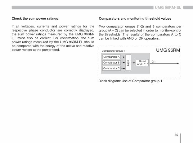
Comparators and monitoring threshold values
Two comparator groups (1-2) and 3 comparators per group (A – C) can be selected in order to monitor/control the thresholds. The results of the comparators A to C can be linked with AND or OR operators.
0/1
Comparator group 1
Comparator A
Comparator B
Comparator C
Logi
c ResultAddr. 616
UMG 96RM
Block diagram: Use of Comparator group 1
56
UMG 96RM-EL
Example: Current monitoring in the neutral line
If the current in the neutral line is greater than 100 A for 60 seconds, the result of the comparator group 1 should be latched for at least 2 minutes. The following must be programmed:
1. Comparator group 1Select comparator group 1 for the limit value monitoring. Since only one limit value is monitored, select comparator A and program it as follows:
The address of the measured value to be monitored by comparator A: Address 110 = 866 (address of the current in the neutral line)
The measured values for the B and C comparators are set to 0. Address 116 = 0 (the comparator is inactive) Address 122 = 0 (the comparator is inactive)
The limit value to be observed. Address 108 = 100 (100 A)
For a minimum exposure time of 2 minutes, the result of the comparator group 1 should be latched if the limit value is exceeded. Address 111 = 120 seconds
For the lead time of 60 seconds, any exceeding should be minimised. Address 112 = 60 seconds
The operator for comparison between the measured value and the limit value. Address 113 = 0 (corresponds >=)
2. Linking comparatorsThe B and C comparators have not been set and are equal to zero.The result of comparator A is issued as a comparator result through the OR link of comparators A, B and C. Address 107 = 0 (OR link)
ResultThe result of the comparator group 1 is latched for at least 2 minutes if the current in the neutral line is greater than 100 A for more than 60 seconds.
57
UMG 96RM-EL
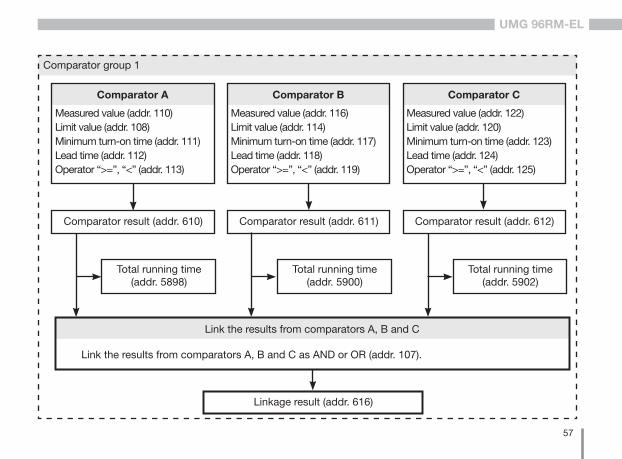
Measured value (addr. 110)Limit value (addr. 108)Minimum turn-on time (addr. 111)Lead time (addr. 112)Operator “>=”, “<” (addr. 113)
Comparator A
Measured value (addr. 116)Limit value (addr. 114)Minimum turn-on time (addr. 117)Lead time (addr. 118)Operator “>=”, “<” (addr. 119)
Comparator B
Measured value (addr. 122)Limit value (addr. 120)Minimum turn-on time (addr. 123)Lead time (addr. 124)Operator “>=”, “<” (addr. 125)
Comparator C
Comparator result (addr. 610) Comparator result (addr. 611) Comparator result (addr. 612)
Total running time(addr. 5898)
Total running time(addr. 5900)
Total running time(addr. 5902)
Link the results from comparators A, B and C
Link the results from comparators A, B and C as AND or OR (addr. 107).
Comparator group 1
Linkage result (addr. 616)
58
UMG 96RM-EL
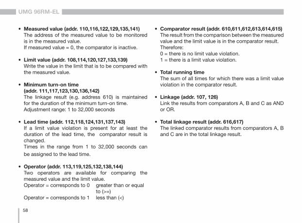
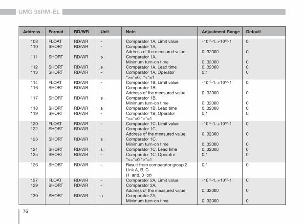
• Measured value (addr. 110,116,122,129,135,141)The address of the measured value to be monitored is in the measured value. If measured value = 0, the comparator is inactive.
• Limit value (addr. 108,114,120,127,133,139)Write the value in the limit that is to be compared with the measured value.
• Minimum turn-on time (addr. 111,117,123,130,136,142)The linkage result (e.g. address 610) is maintained for the duration of the minimum turn-on time. Adjustment range: 1 to 32,000 seconds
• Lead time (addr. 112,118,124,131,137,143)If a limit value violation is present for at least the duration of the lead time, the comparator result is changed. Times in the range from 1 to 32,000 seconds can be assigned to the lead time.
• Operator (addr. 113,119,125,132,138,144)Two operators are available for comparing the measured value and the limit value.Operator = corresponds to 0 greater than or equal to (>=)Operator = corresponds to 1 less than (<)
• Comparator result (addr. 610,611,612,613,614,615)The result from the comparison between the measured value and the limit value is in the comparator result. Therefore:0 = there is no limit value violation.1 = there is a limit value violation.
• Total running time The sum of all times for which there was a limit value violation in the comparator result.
• Linkage (addr. 107, 126)Link the results from comparators A, B and C as AND or OR.
• Total linkage result (addr. 616,617)The linked comparator results from comparators A, B and C are in the total linkage result.
59
UMG 96RM-EL
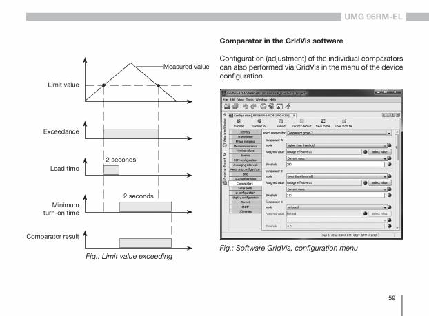
Comparator in the GridVis software
Configuration (adjustment) of the individual comparators can also performed via GridVis in the menu of the device configuration.
Fig.: Software GridVis, configuration menuFig.: Limit value exceeding
Measured value
Limit value
Exceedance
Lead time
Minimumturn-on time
Comparator result
2 seconds
2 seconds
60
UMG 96RM-EL
Service and maintenance
The device is subjected to several different safety tests before leaving the factory and is labelled with a seal. If a device is opened then the safety checks must be repea-ted. Warranty claims will only be accepted if the device is unopened.
Repair and calibration
Repair work and calibration can be carried out by the ma-nufacturer only.
Front film
The front film can be cleaned with a soft cloth and stan-dard household cleaning agent. Do not use acids and products containing acid for cleaning.
Disposal
The UMG 96RM-EL can be reused or recycled as elec-tronic scrap in accordance with the legal provisions. The permanently installed lithium battery must be dis-posed of separately.
Service
Should questions arise, which are not described in this manual, please contact the manufacturer directly.
We will need the following information from you to an-swer any questions:
- Device name (see rating plate),- Serial number (see rating plate),- Software release (see measured value display),- Measuring-circuit voltage and power supply voltage,- Precise description of the error.
Device calibration
The devices are calibrated by the manufacturer at the factory - it is not necessary to recalibrate the de-vice providing that the environmental conditions are complied with.
Calibration intervals
It is recommended to have a new calibration carried out by the manufacturer or an accredited laboratory every 5 years approximately.
61
UMG 96RM-EL
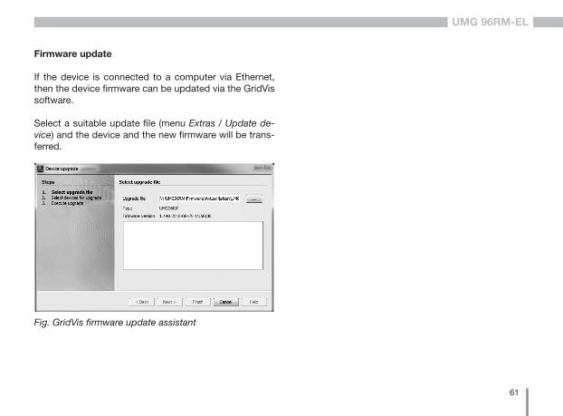
Firmware update
If the device is connected to a computer via Ethernet, then the device firmware can be updated via the GridVis software.
Select a suitable update file (menu Extras / Update de-vice) and the device and the new firmware will be trans-ferred.
Fig. GridVis firmware update assistant
62
UMG 96RM-EL
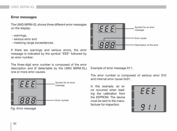
Fig. Error message
Error messages
The UMG 96RM-EL shows three different error messages on the display:
- warnings, - serious error and - metering range exceedances.
If there are warnings and serious errors, the error message is indicated by the symbol "EEE" followed by an error number.
The three-digit error number is composed of the error description and (if detectable by the UMG 96RM-EL) one or more error causes.
Symbol for an error message
Error number
Symbol for an error message
Description of the error
Error cause
Example of error message 911:
The error number is composed of serious error 910 and internal error cause 0x01.
In this example, an er-ror occurred when read-ing the calibration from the EEPROM. The device must be sent to the manu-facturer for inspection.
63
UMG 96RM-EL
Errors Error descriptionEEE810
A failure has been detected in the configu-ration. The configuration will be reset and restored to default values (factory setting) when that failure was displayed. Device has to be re-configured where required.
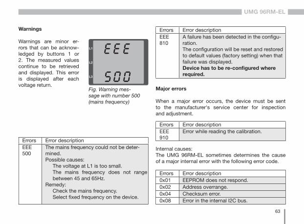
Errors Error descriptionEEE500
The mains frequency could not be deter-mined. Possible causes:
The voltage at L1 is too small.The mains frequency does not range between 45 and 65Hz.
Remedy:Check the mains frequency.Select fixed frequency on the device.
Fig. Warning mes-sage with number 500 (mains frequency)
Warnings
Warnings are minor er-rors that can be acknow-ledged by buttons 1 or 2. The measured values continue to be retrieved and displayed. This error is displayed after each voltage return.
Major errors
When a major error occurs, the device must be sent to the manufacturer's service center for inspection and adjustment.
Errors Error descriptionEEE910
Error while reading the calibration.
Errors Error description0x01 EEPROM does not respond.0x02 Address overrange.0x04 Checksum error.0x08 Error in the internal I2C bus.
Internal causes: The UMG 96RM-EL sometimes determines the cause of a major internal error with the following error code.
64
UMG 96RM-EL
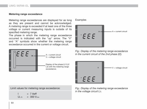
Metering range exceedance
Metering range exceedances are displayed for as long as they are present and cannot be acknowledged. A metering range is exceeded if at least one of the three voltage or current measuring inputs is outside of its specified metering range.The phase in which the metering range exceedance occurred is indicated with the "up" arrow. The "V" and "A" symbols show whether the metering range exceedance occurred in the current or voltage circuit.
I = 7 AeffUL-N = 300 Vrms
Limit values for metering range exceedance:
A = current circuitV = voltage circuit
Display of the phase (L1/L2/L3) with the metering range exceedance.
Examples
A = current circuit
Fig.: Display of the metering range exceedance in the current circuit of the 2nd phase (I2).
V = voltage circuit
Fig.: Display of the metering range exceedance in the voltage circuit L3.
65
UMG 96RM-EL
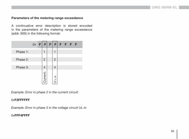
Parameters of the metering range exceedance
A continuative error description is stored encoded in the parameters of the metering range exceedance (addr. 600) in the following format:
Example: Error in phase 2 in the current circuit:
0xF2FFFFFF
Example: Error in phase 3 in the voltage circuit UL-N:
0xFFF4FFFF
F F F F F F F F
Phase 1:
Phase 2:
Phase 3:
1
2
4
Cur
rent
:
1
2
4
U L
-N
0x
66
UMG 96RM-EL
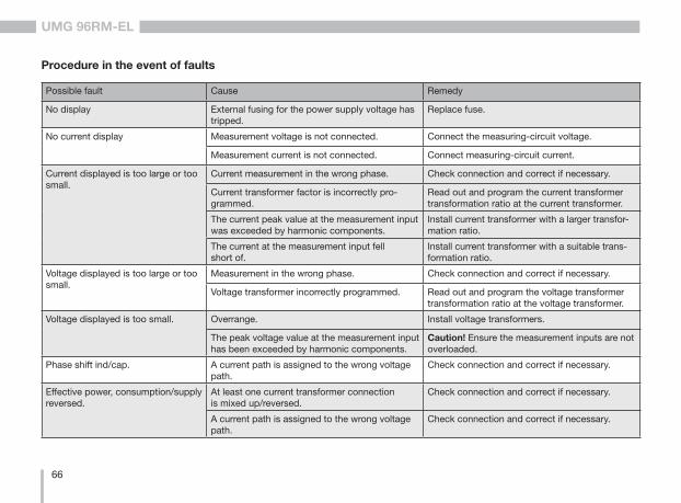
Procedure in the event of faults
Possible fault Cause Remedy
No display External fusing for the power supply voltage has tripped.
Replace fuse.
No current display Measurement voltage is not connected. Connect the measuring-circuit voltage.
Measurement current is not connected. Connect measuring-circuit current.
Current displayed is too large or too small.
Current measurement in the wrong phase. Check connection and correct if necessary.
Current transformer factor is incorrectly pro-grammed.
Read out and program the current transformer transformation ratio at the current transformer.
The current peak value at the measurement input was exceeded by harmonic components.
Install current transformer with a larger transfor-mation ratio.
The current at the measurement input fell short of.
Install current transformer with a suitable trans-formation ratio.
Voltage displayed is too large or too small.
Measurement in the wrong phase. Check connection and correct if necessary.
Voltage transformer incorrectly programmed. Read out and program the voltage transformer transformation ratio at the voltage transformer.
Voltage displayed is too small. Overrange. Install voltage transformers.
The peak voltage value at the measurement input has been exceeded by harmonic components.
Caution! Ensure the measurement inputs are not overloaded.
Phase shift ind/cap. A current path is assigned to the wrong voltage path.
Check connection and correct if necessary.
Effective power, consumption/supply reversed.
At least one current transformer connection is mixed up/reversed.
Check connection and correct if necessary.
A current path is assigned to the wrong voltage path.
Check connection and correct if necessary.
67
UMG 96RM-EL
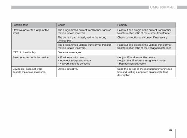
Possible fault Cause Remedy
Effective power too large or too small.
The programmed current transformer transfor-mation ratio is incorrect.
Read out and program the current transformer transformation ratio at the current transformer
The current path is assigned to the wrong voltage path.
Check connection and correct if necessary.
The programmed voltage transformer transfor-mation ratio is incorrect.
Read out and program the voltage transformer transformation ratio at the voltage transformer.
"EEE" in the display See error messages.
No connection with the device. - IP address is incorrect.- Incorrect addressing mode- Network cable is defective
- Adjust IP address at the device.- Adjust the IP address assignment mode- Replace network cable
Device still does not work despite the above measures.
Device defective. Send the device to the manufacturer for inspec-tion and testing along with an accurate fault description.
68
UMG 96RM-EL
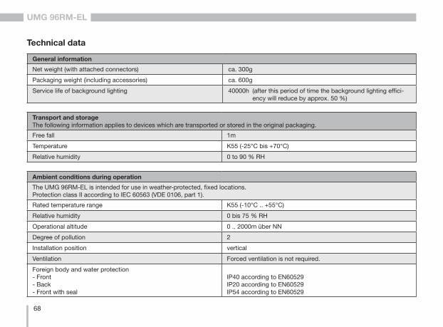
Technical data
General information
Net weight (with attached connectors) ca. 300g
Packaging weight (including accessories) ca. 600g
Service life of background lighting 40000h (after this period of time the background lighting effici-ency will reduce by approx. 50 %)
Transport and storageThe following information applies to devices which are transported or stored in the original packaging.
Free fall 1m
Temperature K55 (-25°C bis +70°C)
Relative humidity 0 to 90 % RH
Ambient conditions during operation
The UMG 96RM-EL is intended for use in weather-protected, fixed locations.Protection class II according to IEC 60563 (VDE 0106, part 1).
Rated temperature range K55 (-10°C .. +55°C)
Relative humidity 0 bis 75 % RH
Operational altitude 0 .. 2000m über NN
Degree of pollution 2
Installation position vertical
Ventilation Forced ventilation is not required.
Foreign body and water protection- Front- Back- Front with seal
IP40 according to EN60529IP20 according to EN60529IP54 according to EN60529
69
UMG 96RM-EL
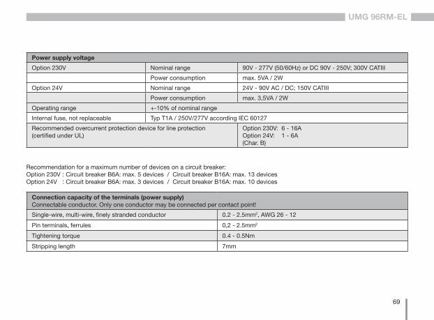
Connection capacity of the terminals (power supply)Connectable conductor. Only one conductor may be connected per contact point!
Single-wire, multi-wire, finely stranded conductor 0.2 - 2.5mm2, AWG 26 - 12
Pin terminals, ferrules 0,2 - 2.5mm2
Tightening torque 0.4 - 0.5Nm
Stripping length 7mm
Power supply voltage
Option 230V Nominal range 90V - 277V (50/60Hz) or DC 90V - 250V; 300V CATIII
Power consumption max. 5VA / 2W
Option 24V Nominal range 24V - 90V AC / DC; 150V CATIII
Power consumption max. 3,5VA / 2W
Operating range +-10% of nominal range
Internal fuse, not replaceable Typ T1A / 250V/277V according IEC 60127
Recommended overcurrent protection device for line protection (certified under UL)
Option 230V: 6 - 16AOption 24V: 1 - 6A(Char. B)
Recommendation for a maximum number of devices on a circuit breaker:Option 230V : Circuit breaker B6A: max. 5 devices / Circuit breaker B16A: max. 13 devices Option 24V : Circuit breaker B6A: max. 3 devices / Circuit breaker B16A: max. 10 devices

70
UMG 96RM-EL
Voltage metering
Three-phase, 4-wire systems with nominal voltages up to 277V/480V (+-10%)
Three-phase, 3-wire systems, unearthed, with nominal voltages up to
IT 480V (+-10%)
Overvoltage category 300V CAT III
Rated surge voltage 4kV
Metering range L-N 01) .. 300 Vrms(max. overvoltage 520 Vrms )
Metering range L-L 01) .. 520Vrms(max. overvoltage 900Vrms )
Resolution 0.01V
Crest factor 2.45 (relative to the metering range)
Impedance 3MΩ/phase
Power consumption approx. 0.1 VA
Sampling rate 21.33kHz (50Hz), 25.6 kHz (60Hz) per measuring channel
Mains frequency- Resolution
45Hz .. 65Hz0.01Hz
1) The UMG 96RM-EL can only detect measurements when a voltage L1-N greater than 20V eff (4-wire measurement) at voltage input V1 or a voltage L1-L2 greater than 34V eff (3-wire measurement) is applied.
71
UMG 96RM-EL
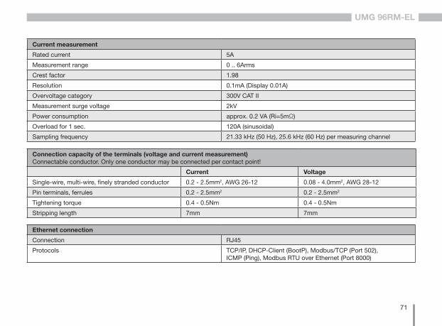
Ethernet connection
Connection RJ45
Protocols TCP/IP, DHCP-Client (BootP), Modbus/TCP (Port 502),ICMP (Ping), Modbus RTU over Ethernet (Port 8000)
Connection capacity of the terminals (voltage and current measurement)Connectable conductor. Only one conductor may be connected per contact point!
Current Voltage
Single-wire, multi-wire, finely stranded conductor 0.2 - 2.5mm2, AWG 26-12 0.08 - 4.0mm2, AWG 28-12
Pin terminals, ferrules 0.2 - 2.5mm2 0.2 - 2.5mm2
Tightening torque 0.4 - 0.5Nm 0.4 - 0.5Nm
Stripping length 7mm 7mm
Current measurement
Rated current 5A
Measurement range 0 .. 6Arms
Crest factor 1.98
Resolution 0.1mA (Display 0.01A)
Overvoltage category 300V CAT II
Measurement surge voltage 2kV
Power consumption approx. 0.2 VA (Ri=5mΩ)
Overload for 1 sec. 120A (sinusoidal)
Sampling frequency 21.33 kHz (50 Hz), 25.6 kHz (60 Hz) per measuring channel
72
UMG 96RM-EL
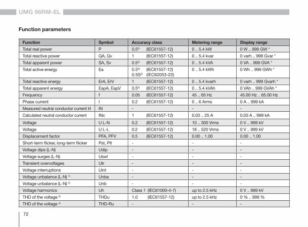
Function parameters
Function Symbol Accuracy class Metering range Display range
Total real power P 0.55) (IEC61557-12) 0 .. 5.4 kW 0 W .. 999 GW *
Total reactive power QA, Qv 1 (IEC61557-12) 0 .. 5.4 kvar 0 varh .. 999 Gvar *
Total apparent power SA, Sv 0.55) (IEC61557-12) 0 .. 5.4 kVA 0 VA .. 999 GVA *
Total active energy Ea 0.55) (IEC61557-12)0.5S5) (IEC62053-22)
0 .. 5.4 kWh 0 Wh .. 999 GWh *
Total reactive energy ErA, ErV 1 (IEC61557-12) 0 .. 5.4 kvarh 0 varh .. 999 Gvarh *
Total apparent energy EapA, EapV 0.55) (IEC61557-12) 0 .. 5.4 kVAh 0 VAh .. 999 GVAh *
Frequency f 0.05 (IEC61557-12) 45 .. 65 Hz 45.00 Hz .. 65.00 Hz
Phase current I 0.2 (IEC61557-12) 0 .. 6 Arms 0 A .. 999 kA
Measured neutral conductor current I4 IN - - -
Calculated neutral conductor current INc 1 (IEC61557-12) 0.03 .. 25 A 0.03 A .. 999 kA
Voltage U L-N 0.2 (IEC61557-12) 10 .. 300 Vrms 0 V .. 999 kV
Voltage U L-L 0.2 (IEC61557-12) 18 .. 520 Vrms 0 V .. 999 kV
Displacement factor PFA, PFV 0.5 (IEC61557-12) 0.00 .. 1.00 0.00 .. 1.00
Short-term flicker, long-term flicker Pst, Plt - - -
Voltage dips (L-N) Udip - - -
Voltage surges (L-N) Uswl - - -
Transient overvoltages Utr - - -
Voltage interruptions Uint - - -
Voltage unbalance (L-N) 1) Unba - - -
Voltage unbalance (L-N) 2) Unb - - -
Voltage harmonics Uh Class 1 (IEC61000-4-7) up to 2.5 kHz 0 V .. 999 kV
THD of the voltage 3) THDu 1.0 (IEC61557-12) up to 2.5 kHz 0 % .. 999 %
THD of the voltage 4) THD-Ru - - -
73
UMG 96RM-EL
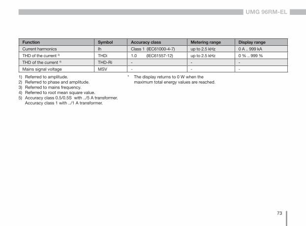
Function Symbol Accuracy class Metering range Display range
Current harmonics Ih Class 1 (IEC61000-4-7) up to 2.5 kHz 0 A .. 999 kA
THD of the current 3) THDi 1.0 (IEC61557-12) up to 2.5 kHz 0 % .. 999 %
THD of the current 4) THD-Ri - - -
Mains signal voltage MSV - - -
* The display returns to 0 W when the maximum total energy values are reached.
1) Referred to amplitude.2) Referred to phase and amplitude.3) Referred to mains frequency.4) Referred to root mean square value.5) Accuracy class 0.5/0.5S with ../5 A transformer. Accuracy class 1 with ../1 A transformer.
74
UMG 96RM-EL
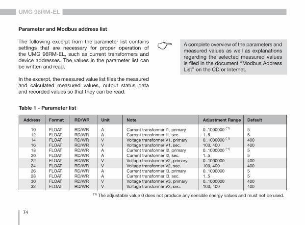
Table 1 - Parameter list
10 FLOAT RD/WR A Current transformer I1, primary 0..1000000 (*1) 5 12 FLOAT RD/WR A Current transformer I1, sec. 1..5 5 14 FLOAT RD/WR V Voltage transformer V1, primary 0..1000000 (*1) 400 16 FLOAT RD/WR V Voltage transformer V1, sec. 100, 400 400 18 FLOAT RD/WR A Current transformer I2, primary 0..1000000 (*1) 5 20 FLOAT RD/WR A Current transformer I2, sec. 1..5 5 22 FLOAT RD/WR V Voltage transformer V2, primary 0..1000000 400 24 FLOAT RD/WR V Voltage transformer V2, sec. 100, 400 400 26 FLOAT RD/WR A Current transformer I3, primary 0..1000000 5 28 FLOAT RD/WR A Current transformer I3, sec. 1..5 5 30 FLOAT RD/WR V Voltage transformer V3, primary 0..1000000 400 32 FLOAT RD/WR V Voltage transformer V3, sec. 100, 400 400
Address Format RD/WR Unit Note Adjustment Range Default
Parameter and Modbus address list
The following excerpt from the parameter list contains settings that are necessary for proper operation of the UMG 96RM-EL, such as current transformers and device addresses. The values in the parameter list can be written and read.
In the excerpt, the measured value list files the measured and calculated measured values, output status data and recorded values so that they can be read.
C A complete overview of the parameters and measured values as well as explanations regarding the selected measured values is filed in the document “Modbus Address List” on the CD or Internet.
(*1) The adjustable value 0 does not produce any sensible energy values and must not be used.
75
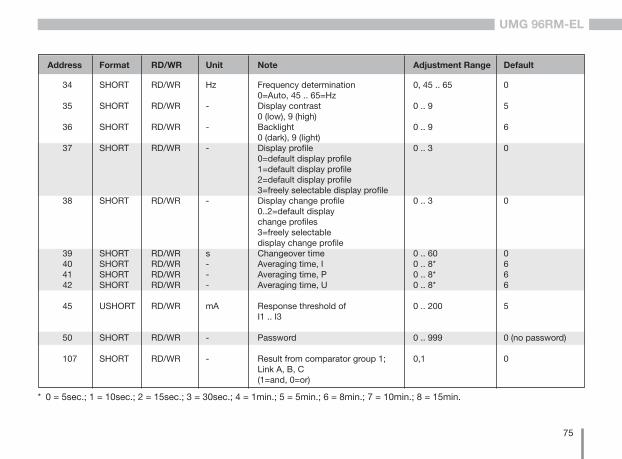
UMG 96RM-EL
34 SHORT RD/WR Hz Frequency determination 0, 45 .. 65 0 0=Auto, 45 .. 65=Hz 35 SHORT RD/WR - Display contrast 0 .. 9 5 0 (low), 9 (high) 36 SHORT RD/WR - Backlight 0 .. 9 6 0 (dark), 9 (light) 37 SHORT RD/WR - Display profile 0 .. 3 0 0=default display profile 1=default display profile 2=default display profile 3=freely selectable display profile 38 SHORT RD/WR - Display change profile 0 .. 3 0 0..2=default display change profiles 3=freely selectable display change profile 39 SHORT RD/WR s Changeover time 0 .. 60 0 40 SHORT RD/WR - Averaging time, I 0 .. 8* 6 41 SHORT RD/WR - Averaging time, P 0 .. 8* 6 42 SHORT RD/WR - Averaging time, U 0 .. 8* 6
45 USHORT RD/WR mA Response threshold of 0 .. 200 5 I1 .. I3
50 SHORT RD/WR - Password 0 .. 999 0 (no password)
107 SHORT RD/WR - Result from comparator group 1; 0,1 0 Link A, B, C (1=and, 0=or)
Address Format RD/WR Unit Note Adjustment Range Default
* 0 = 5sec.; 1 = 10sec.; 2 = 15sec.; 3 = 30sec.; 4 = 1min.; 5 = 5min.; 6 = 8min.; 7 = 10min.; 8 = 15min.
76
UMG 96RM-EL
Address Format RD/WR Unit Note Adjustment Range Default
108 FLOAT RD/WR - Comparator 1A, Limit value -1012-1..+1012-1 0 110 SHORT RD/WR - Comparator 1A, Address of the measured value 0..32000 0 111 SHORT RD/WR s Comparator 1A, Minimum turn-on time 0..32000 0 112 SHORT RD/WR s Comparator 1A, Lead time 0..32000 0 113 SHORT RD/WR - Comparator 1A, Operator 0,1 0 “>=”=0, “<”=1 114 FLOAT RD/WR - Comparator 1B, Limit value -1012-1..+1012-1 0 116 SHORT RD/WR - Comparator 1B, Address of the measured value 0..32000 0 117 SHORT RD/WR s Comparator 1B, Minimum turn-on time 0..32000 0 118 SHORT RD/WR s Comparator 1B, Lead time 0..32000 0 119 SHORT RD/WR - Comparator 1B, Operator 0,1 0 “>=”=0 “<”=1 120 FLOAT RD/WR - Comparator 1C, Limit value -1012-1..+1012-1 0 122 SHORT RD/WR - Comparator 1C, Address of the measured value 0..32000 0 123 SHORT RD/WR s Comparator 1C, Minimum turn-on time 0..32000 0 124 SHORT RD/WR s Comparator 1C, Lead time 0..32000 0 125 SHORT RD/WR - Comparator 1C, Operator 0,1 0 “>=”=0 “<”=1 126 SHORT RD/WR - Result from comparator group 2; 0,1 0 Link A, B, C (1=and, 0=or) 127 FLOAT RD/WR - Comparator 2A, Limit value -1012-1..+1012-1 0 129 SHORT RD/WR - Comparator 2A, Address of the measured value 0..32000 0 130 SHORT RD/WR s Comparator 2A, Minimum turn-on time 0..32000 0
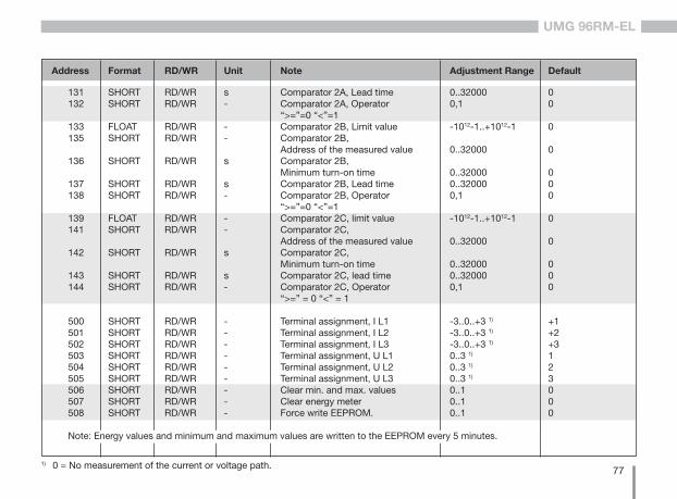
77
UMG 96RM-EL
Address Format RD/WR Unit Note Adjustment Range Default
1) 0 = No measurement of the current or voltage path.
131 SHORT RD/WR s Comparator 2A, Lead time 0..32000 0 132 SHORT RD/WR - Comparator 2A, Operator 0,1 0 “>=”=0 “<”=1 133 FLOAT RD/WR - Comparator 2B, Limit value -1012-1..+1012-1 0 135 SHORT RD/WR - Comparator 2B, Address of the measured value 0..32000 0 136 SHORT RD/WR s Comparator 2B, Minimum turn-on time 0..32000 0 137 SHORT RD/WR s Comparator 2B, Lead time 0..32000 0 138 SHORT RD/WR - Comparator 2B, Operator 0,1 0 “>=”=0 “<”=1 139 FLOAT RD/WR - Comparator 2C, limit value -1012-1..+1012-1 0 141 SHORT RD/WR - Comparator 2C, Address of the measured value 0..32000 0 142 SHORT RD/WR s Comparator 2C, Minimum turn-on time 0..32000 0 143 SHORT RD/WR s Comparator 2C, lead time 0..32000 0 144 SHORT RD/WR - Comparator 2C, Operator 0,1 0 “>=” = 0 “<” = 1
500 SHORT RD/WR - Terminal assignment, I L1 -3..0..+3 1) +1 501 SHORT RD/WR - Terminal assignment, I L2 -3..0..+3 1) +2 502 SHORT RD/WR - Terminal assignment, I L3 -3..0..+3 1) +3 503 SHORT RD/WR - Terminal assignment, U L1 0..3 1) 1 504 SHORT RD/WR - Terminal assignment, U L2 0..3 1) 2 505 SHORT RD/WR - Terminal assignment, U L3 0..3 1) 3 506 SHORT RD/WR - Clear min. and max. values 0..1 0 507 SHORT RD/WR - Clear energy meter 0..1 0 508 SHORT RD/WR - Force write EEPROM. 0..1 0
Note: Energy values and minimum and maximum values are written to the EEPROM every 5 minutes.
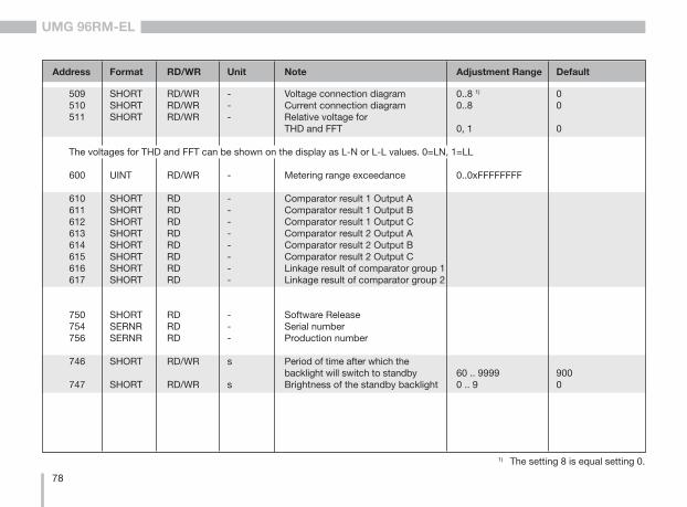
78
UMG 96RM-EL
Address Format RD/WR Unit Note Adjustment Range Default
509 SHORT RD/WR - Voltage connection diagram 0..8 1) 0 510 SHORT RD/WR - Current connection diagram 0..8 0 511 SHORT RD/WR - Relative voltage for THD and FFT 0, 1 0
The voltages for THD and FFT can be shown on the display as L-N or L-L values. 0=LN, 1=LL
600 UINT RD/WR - Metering range exceedance 0..0xFFFFFFFF
610 SHORT RD - Comparator result 1 Output A 611 SHORT RD - Comparator result 1 Output B 612 SHORT RD - Comparator result 1 Output C 613 SHORT RD - Comparator result 2 Output A 614 SHORT RD - Comparator result 2 Output B 615 SHORT RD - Comparator result 2 Output C 616 SHORT RD - Linkage result of comparator group 1 617 SHORT RD - Linkage result of comparator group 2
750 SHORT RD - Software Release 754 SERNR RD - Serial number 756 SERNR RD - Production number
746 SHORT RD/WR s Period of time after which the backlight will switch to standby 60 .. 9999 900 747 SHORT RD/WR s Brightness of the standby backlight 0 .. 9 0
1) The setting 8 is equal setting 0.

79
UMG 96RM-EL
Type Size Minimum Maximum
short 16 bit -215 215 -1
ushort 16 bit 0 216 -1
int 32 bit -231 231 -1
uint 32 bit 0 232 -1
float 32 bit IEEE 754 IEEE 754
Number formats
C Notes on saving measurement values and configuration data:
• The following measurement values are saved at least every 5 minutes:• Comparator timer• S0 meter readings• Minimum / maximum / mean values• Energy values
• Configuration data is saved immediately!
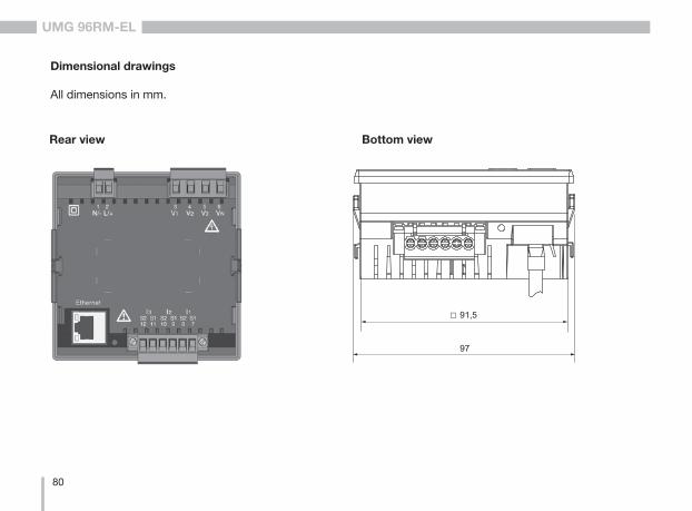
80
UMG 96RM-EL
Dimensional drawings
All dimensions in mm.
Rear view Bottom view
97
91,5
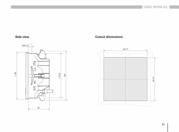
81
UMG 96RM-EL
Side view
92+0
,8
92+0,8
Cutout dimensions
96
max. 6
42
91
,5
104
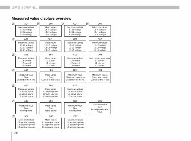
82
UMG 96RM-EL
Measured value displays overview
Measured valuesL1-N voltage L2-N voltageL3-N voltage
A01
Measured values L1-L2 voltage L2-L3 voltage L3-L1 voltage
A02
Measured values L1 current L2 current L3 current
A03
Measured value Sum
Current in the N line
A04
Mean valuesL1-N voltage L2-N voltageL3-N voltage
B01
Mean values L1-L2 voltage L2-L3 voltage L3-L1 voltage
B02
Mean values L1 currentL2 currentL3 current
B03
Mean value Sum
Current in the N line
B04
Maximum valuesL1-N voltageL2-N voltageL3-N voltage
C01
Maximum valuesL1-L2 voltageL2-L3 voltageL3-L1 voltage
C02
Maximum valuesL1 currentL2 currentL3 current
C03
Maximum value Measured value sum Current in the N line
C04
Minimum valuesL1-N voltageL2-N voltageL3-N voltage
D01
Minimum valuesL1-L2 voltageL2-L3 voltageL3-L1 voltage
D02
Max. values (mean value)
L1 currentL2 currentL3 current
D03
Maximum valuesSum mean value
Current in the N line
D04
Measured values L1 active powerL2 active powerL3 active power
A05
Measured value Sum
Active power
A06
Mean valueL1 active powerL2 active powerL3 active power
B05
Mean value Sum
Active power
B06
Maximum values L1 active powerL2 active powerL3 active power
C05
Maximum value Sum
Active power
C06
Maximum valueSum
Active power mean value
D06
Measured valuesL1 apparent powerL2 apparent powerL3 apparent power
A07
Mean valuesL1 apparent powerL2 apparent powerL3 apparent power
B07
Maximum valuesL1 apparent powerL2 apparent powerL3 apparent power
C07
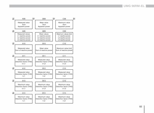
83
UMG 96RM-EL
Measured valueDistortion factor (THD)
I L1
A12
Measured valueDistortion factor (THD)
I L2
B12
Measured valueDistortion factor (THD)
I L3
C12
Maximum valueDistortion factor (THD)
U L1
A13
Maximum valueDistortion factor (THD)
I L1
A14
Maximum valueDistortion factor (THD)
U L2
B13
Maximum valueDistortion factor (THD)
I L2
B14
Maximum valueDistortion factor (THD)
U L3
C13
Maximum valueDistortion factor (THD)
I L3
C14
Measured value Sum
Apparent power
A08
Measured values L1 reactive power L2 reactive power L3 reactive power
A09
Measured valueSum of reactive power
A10
Measured valueDistortion factor (THD)
U L1
A11
Mean value Sum
Apparent power
B08
Mean valuesL1 reactive powerL2 reactive powerL3 reactive power
B09
Mean valueSum of reactive power
B10
Measured valueDistortion factor (THD)
U L2
B11
Maximum value Sum
Apparent power
C08
Maximum values (ind) L1 reactive powerL2 reactive powerL3 reactive power
C09
Maximum value (ind)Sum of reactive power
C10
Measured valueDistortion factor (THD)
U L3
C11
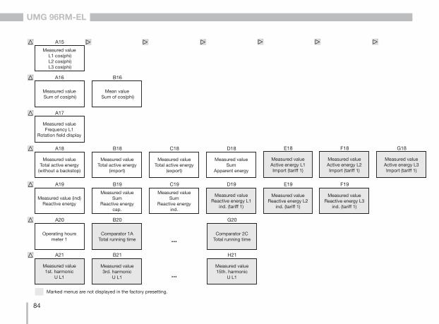
84
UMG 96RM-EL
Measured value L1 cos(phi) L2 cos(phi) L3 cos(phi)
A15
Measured value Sum of cos(phi)
A16
Measured value Frequency L1
Rotation field display
A17
Measured value Total active energy
(without a backstop)
A18
Mean value Sum of cos(phi)
B16
Measured valueTotal active energy
(import)
B18
Measured valueTotal active energy
(export)
C18
Measured valueSum
Apparent energy
D18
Measured value1st. harmonic
U L1
A21
Measured value3rd. harmonic
U L1
B21
...Measured value15th. harmonic
U L1
H21
Measured value (ind)Reactive energy
A19
Operating hoursmeter 1
A20
Measured value Sum
Reactive energycap.
B19
Comparator 1ATotal running time
B20
Measured valueSum
Reactive energyind.
C19
...Comparator 2C
Total running time
G20
Marked menus are not displayed in the factory presetting.
Measured valueActive energy L1 Import (tariff 1)
E18
Measured valueActive energy L2 Import (tariff 1)
F18
Measured valueActive energy L3 Import (tariff 1)
G18
Measured valueReactive energy L1
ind. (tariff 1)
D19
Measured valueReactive energy L2
ind. (tariff 1)
E19
Measured valueReactive energy L3
ind. (tariff 1)
F19
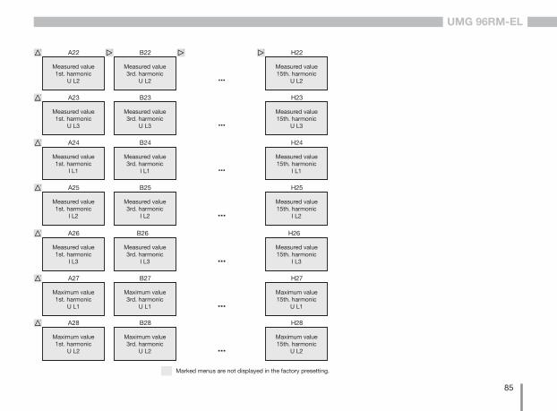
85
UMG 96RM-EL
Measured value1st. harmonic
I L3
A26
Maximum value1st. harmonic
U L1
A27
Maximum value1st. harmonic
U L2
A28
Measured value3rd. harmonic
I L3
B26
Maximum value3rd. harmonic
U L1
B27
Maximum value3rd. harmonic
U L2
B28
...
...
...
Measured value15th. harmonic
I L3
H26
Maximum value15th. harmonic
U L1
H27
Maximum value15th. harmonic
U L2
H28
Marked menus are not displayed in the factory presetting.
Measured value1st. harmonic
U L2
A22
Measured value1st. harmonic
U L3
A23
Measured value1st. harmonic
I L1
A24
Measured value3rd. harmonic
U L2
B22
Measured value3rd. harmonic
U L3
B23
Measured value3rd. harmonic
I L1
B24
...
...
...
Measured value15th. harmonic
U L2
H22
Measured value15th. harmonic
I L1
H24
Measured value15th. harmonic
U L3
H23
Measured value1st. harmonic
I L2
A25
Measured value3rd. harmonic
I L2
B25
...Measured value15th. harmonic
I L2
H25
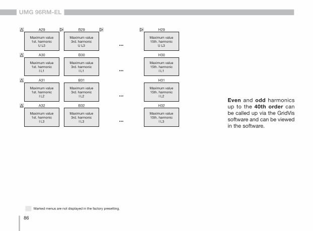
86
UMG 96RM-EL
Maximum value1st. harmonic
U L3
A29
Maximum value1st. harmonic
I L1
A30
Maximum value3rd. harmonic
U L3
B29
Maximum value3rd. harmonic
I L1
B30
...
...Maximum value15th. harmonic
I L1
H30
Maximum value15th. harmonic
U L3
H29
Maximum value1st. harmonic
I L2
A31
Maximum value1st. harmonic
I L3
A32
Maximum value3rd. harmonic
I L2
B31
Maximum value3rd. harmonic
I L3
B32
...
...Maximum value15th. harmonic
I L3
H32
Maximum value15th. harmonic
I L2
H31
Marked menus are not displayed in the factory presetting.
Even and odd harmonics up to the 40th order can be called up via the GridVis software and can be viewed in the software.
87
UMG 96RM-EL
This equipment has been tested and found to comply with the limits for a Class B digital device, pursuant to part 15 of the FCC Rules. These limits are designed to provide reasonable protection against harmful interference in a residential installation. This equip-ment generates, uses and can radiate radio frequency energy and, if not installed and used in accordance with the instructions, may cause harmful interference to radio communications. However, there is no guarantee that interference will not occur in a particular installation. If this equipment does cause harmful interference to radio or television reception, which can be determined by turning the equipment off and on, the user is encouraged to try to correct the interference by one or more of the following measures: —Reorient or relocate the receiving antenna. —Increase the separation between the equipment and receiver. —Connect the equipment into an outlet on a circuit different from that to which the receiver is connected. —Consult the dealer or an experienced radio/TV technician for help.
Code of Federal Regulations, Title 47, Part 15, Subpart B - Unintentional Radiators
FCC Compliance Statement
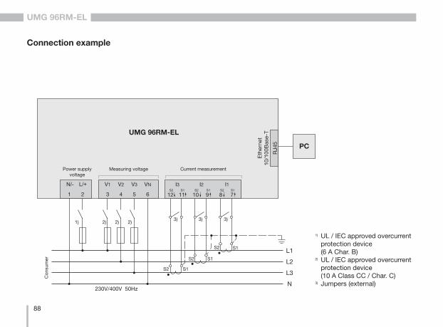
88
UMG 96RM-EL
UMG 96RM-EL
Versorgungs-spannung
Eth
erne
t10
/100
Bas
e-T
PC
Spannungsmessung
RJ4
5
Strommessung
V1 V2 V3 VN
3 4 5 61 2
N/- L/+
S2 S1
S2
S2
S1
S1 L1
L2
L3
Verb
rauc
her
230V/400V 50HzN
S2 S1 S2 S1 S2 S1
Connection example
1) UL / IEC approved overcurrent protection device (6 A Char. B)2) UL / IEC approved overcurrent protection device (10 A Class CC / Char. C)3) Jumpers (external)
2)1) 2) 2)3) 3)3)
Power supply voltage
Measuring voltage Current measurement
Con
sum
er
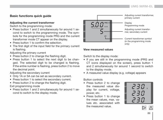
89
UMG 96RM-EL
Basic functions quick guide
Adjusting the current transformerSwitch to the programming mode:• Press button 1 and 2 simultaneously for around 1 se-
cond to switch to the programming mode. The sym-bols for the programming mode PRG and the current transformer mode CT appear on the display.
• Press button 1 to confirm the selection. • The first digit of the input field for the primary current
is flashing.Adjusting the primary current• Press button 2 to change the flashing digit. • Press button 1 to select the next digit to be chan-
ged. The selected digit to be changed is flashing. If the entire number is flashing, press button 2 to move the decimal point.
Adjusting the secondary current• Only 1A or 5A can be set as secondary current. • Press button 1 to select the secondary current.• Press button 2 to change the flashing digit. Exit programming mode• Press button 1 and 2 simultaneously for around 1 se-
cond to switch to the display mode.
View measured values
Switch to the display mode:• If you are still in the programming mode (PRG and
CT icons displayed on the screen), press button 1 and 2 simultaneously for around 1 second to switch to the display mode.
• A measured value display (e.g. voltage) appears
Current transformer symbol(in the programming mode only)
Adjusting current transformer, primary current
DisplayProgramming mode
Adjusting current transfor-mer, secondary current
Button controls• Press button 2 to change
the measured value dis-play for current, voltage, power, etc.
• Press button 1 to change the mean values, max. va-lues etc. associated with the measured value.
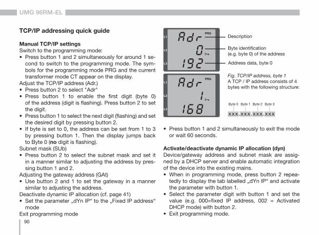
90
UMG 96RM-EL
TCP/IP addressing quick guide
Manual TCP/IP settingsSwitch to the programming mode:• Press button 1 and 2 simultaneously for around 1 se-
cond to switch to the programming mode. The sym-bols for the programming mode PRG and the current transformer mode CT appear on the display.
Adjust the TCP/IP address (Adr.)• Press button 2 to select "Adr"• Press button 1 to enable the first digit (byte 0)
of the address (digit is flashing). Press button 2 to set the digit.
• Press button 1 to select the next digit (flashing) and set the desired digit by pressing button 2.
• If byte is set to 0, the address can be set from 1 to 3 by pressing button 1. Then the display jumps back to Byte 0 (no digit is flashing).
Subnet mask (SUb)• Press button 2 to select the subnet mask and set it
in a manner similar to adjusting the address by pres-sing button 1 and 2.
Adjusting the gateway address (GAt)• Use button 2 and 1 to set the gateway in a manner
similar to adjusting the address. Deactivate dynamic IP allocation (cf. page 41)• Set the parameter „dYn IP“ to the „Fixed IP address“
modeExit programming mode
Description
Byte identification (e.g. byte 0) of the address
Address data, byte 0
Fig. TCP/IP address, byte 1A TCP / IP address consists of 4 bytes with the following structure:
xxx.xxx.xxx.xxx
Byte 1Byte 0 Byte 2 Byte 3
• Press button 1 and 2 simultaneously to exit the mode or wait 60 seconds.
Activate/deactivate dynamic IP allocation (dyn)Device/gateway address and subnet mask are assig-ned by a DHCP server and enable automatic integration of the device into the existing mains.• When in programming mode, press button 2 repea-
tedly to display the tab labelled „dYn IP“ and activate the parameter with button 1.
• Select the parameter digit with button 1 and set the value (e.g. 000=fixed IP address, 002 = Activated DHCP mode) with button 2.
• Exit programming mode.