power assisted system (power steering) ps
TRANSCRIPT

POWER ASSISTED SYSTEM (POWER STEERING)
PS
Page1. General Description ....................................................................................22. Steering Wheel..........................................................................................233. Universal Joint...........................................................................................244. Tilt Steering Column..................................................................................265. Steering Gearbox [LHD MODEL] ..............................................................296. Steering Gearbox [RHD MODEL] .............................................................487. Pipe Assembly [LHD MODEL] ..................................................................668. Pipe Assembly [RHD MODEL]..................................................................749. Oil Pump ...................................................................................................82
10. Reservoir Tank..........................................................................................8811. Power Steering Fluid.................................................................................8912. General Diagnostic Table..........................................................................90

POWER ASSISTED SYSTEM (POWER STEERING)GENERAL DESCRIPTION
1. General DescriptionA: SPECIFICATIONS
Item Designation
Whole system
Minimum turning diameter m (ft) 10.6 (34.8)
Steering angle (Inside-Outside) 36° 25′ — 32° 00′Steering wheel diameter mm (in) 385 (15.16)
Maximum rotation 3.0
Gearbox
Type Rack and pinion, Integral
Backlash 0 (Automatically adjustable)
Valve (Power steering system) Rotary valve
Pump (Power steering system)
Type Vane pump
Oil tank Installed on body
Output cm3 (cu in)/rev. 7.2 (0.439)
Relief pressure kPa (kg/cm2, psi)7,360 — 8,050
(75 — 82, 1,067 — 1,166)
Hydraulic fluid control Dropping in response to increased engine revolutions
Hydraulic fluid 2 (US qt, Imp qt)/min1,000 rpm: 7 (7.4, 6.2)3,000 rpm: 5 (5.3, 4.4)
Range of revolution rpm 595 — 8,925
Revolving direction Clockwise (Viewed from pulley side)
Working fluid(Power steering sys-tem)
Name ATF DEXRON III or equivalent
Capacity2 (US qt, Imp qt)
Oil tank 0.3 (0.3, 0.3)
Total 0.7 (0.7, 0.6)
PS-2

POWER ASSISTED SYSTEM (POWER STEERING)GENERAL DESCRIPTION
CAUTION:This table lists various clearances that must be correctly adjusted to ensure the normal vehicle driving without interfering noise, or any other faults.
Model LHD RHD
Steering wheel Free play mm (in) 17 (0.67)
Turning angleInner tire & wheel 32°25′±1°30′Outer tire & wheel 32°00′±1°30′
Steering shaftClearance between steering wheel and column cover
mm (in) 3.0 (0.118)
Steering gear-box(Power steer-ing system)
Sliding resistance N (kgf, lb) 400 (41, 90) or less
Rack shaft play in radial direction
Right-turn steering mm (in) 0.19 (0.0075) or less
Horizontal movement: 0.19 (0.0075) or lessVertical movement: 0.3 (0.012) or less
Left-turn steering mm (in)
Horizontal movement: 0.15 (0.0059) or lessVertical movement: 0.3 (0.012) or less
0.19 (0.0075) or less
Input shaft play
In radial direction mm (in) 0.18 (0.0071) or less
In axial direction mm (in) 0.5 (0.020) or less
Turning resistance N (kgf, lb)
Maximum allowable value:Less than 10.5 N (1.1 kgf, 2.4 lb)Difference between right and left
sliding resistance: Less than 20 %
Oil pump(Power steer-ing system)
Pulley shaftRadial play mm (in) 0.4 (0.016) or less
Axial play mm (in) 0.9 (0.035) or less
PulleyDitch deflection mm (in) 1.0 (0.039) or less
Resistance to rotation N (kgf, lb) 9.22 (0.94, 2.07) or less
Regular pressure kPa (kg/cm2, psi) 981 (10, 142) or less
Steering wheel effort (Power steer-ing system)
At standstill with engine idling on a con-crete road
N (kgf, lb) 31.4 (3.2, 7.1) or less
At standstill with engine stalled on a concrete road
N (kgf, lb) 294.2 (30, 66.2) or less
Recommended power steering fluid Manufacturer
ATF DEXRON III or equivalent
B.P.
CALTEX
CASTROL
MOBIL
SHELL
TEXACO
PS-3
POWER ASSISTED SYSTEM (POWER STEERING)GENERAL DESCRIPTION
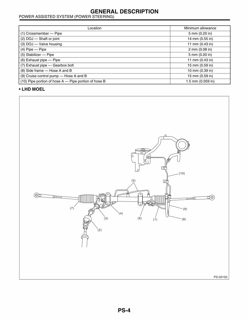
• LHD MOEL
Location Minimum allowance
(1) Crossmember — Pipe 5 mm (0.20 in)
(2) DOJ — Shaft or joint 14 mm (0.55 in)
(3) DOJ — Valve housing 11 mm (0.43 in)
(4) Pipe — Pipe 2 mm (0.08 in)
(5) Stabilizer — Pipe 5 mm (0.20 in)
(6) Exhaust pipe — Pipe 11 mm (0.43 in)
(7) Exhaust pipe — Gearbox bolt 15 mm (0.59 in)
(8) Side frame — Hose A and B 10 mm (0.39 in)
(9) Cruise control pump — Hose A and B 15 mm (0.59 in)
(10) Pipe portion of hose A — Pipe portion of hose B 1.5 mm (0.059 in)
PS-00193
(1) (8)
(5)
(7)
(4)
(6)(3)
(2)
(10)
(9)
PS-4

POWER ASSISTED SYSTEM (POWER STEERING)GENERAL DESCRIPTION
• RHD MODEL
PS-00183
(1)
(9)
(8)
(5)
(7)(4)
(3)
(2)
(6)
PS-5

POWER ASSISTED SYSTEM (POWER STEERING)GENERAL DESCRIPTION
B: COMPONENT1. STEERING WHEEL AND COLUMN
(1) Bushing (5) Steering wheel Tightening torque: N·m (kgf-m, ft-lb)(2) Steering shaft (6) Airbag module T1: 1.2 (0.12, 0.9)(3) Steering roll connector (7) Lower steering wheel cover T2: 25 (2.5, 18.1)(4) Column cover T3: 45 (4.6, 33.2)
PS-00002
T3
(5)
(6)
(2)
(4)
(7)
T2
T1
(3)
(1)
PS-6

POWER ASSISTED SYSTEM (POWER STEERING)GENERAL DESCRIPTION
2. POWER ASSISTED SYSTEM• LHD MODEL
PS-00184
T1
T11
T13T10 T5
T15
T4
T14
T4
T14
T15
T10
T13
(58)(18)
(19)
(19)
(19) T5
T9
T9
T8
T8T1
T4
T4
T2
T2
T3
T6
T7
T9T9
T2
T12
(10)
(9)
(4)
(4)
(4)
(2)
(1)
(3)(6)
(5)
(58)
(57)
(8)
(12)
(15)
(13)
(14)
(16)
(B)
(6)(2)
(57)(16)
(4)
(4)
(9)
(8)
(10)
(5)(4)
(58)
T2
T5
T4
T2
T3
T7
T6
T9
T11
(14)
(13)
(4)
(12)
(3)
T12(1)(A)
(11)(11)
PS-7

POWER ASSISTED SYSTEM (POWER STEERING)GENERAL DESCRIPTION
(A) NON-TURBO MODEL (24) Oil seal (50) Steering body
(B) TURBO MODEL (25) Ball bearing (51) Oil seal
(26) Seal ring (52) Piston ring
(1) Eye bolt (27) Pinion and valve ASSY (53) Rack
(2) Pipe C (28) Oil seal (54) Rack bushing
(3) Gasket (29) Back-up washer (55) Rack stopper
(4) Clip (30) Ball bearing (56) Circlip
(5) Pipe D (31) Snap ring (57) Suction hose
(6) Clamp E (32) Lock nut (58) Hose
(7) O-ring (33) Adjusting screw
(8) Cap (34) Spring Tightening torque: N·m (kgf-m, ft-lb)(9) Reservoir tank (35) Sleeve T1: 6 (0.6, 4.3)
(10) Reservoir tank bracket (36) Adapter T2: 7.4 (0.75, 5.4)(11) Pulley (37) Clamp T3: 8 (0.8, 5.8)(12) Oil pump (38) Cotter pin T4: 13 (1.3, 9.4)(13) Bracket (39) Castle nut T5: 15 (1.5, 10.8)(14) Belt tension nut (40) Dust cover T6: 15.7 (1.6, 11.6)(15) Bush (41) Clip T7: 22 (2.2, 15.9)(16) Belt cover (42) Tie-rod end T8: 24 (2.4, 17.4)(17) Pipe E (43) Clip T9: 25 (2.5, 18.1)(18) Pipe F (44) Boot T10: 27 (2.75, 19.9)(19) Clamp plate (45) Band T11: 37.3 (3.8, 27.5)(20) Universal joint (46) Tie-rod T12: 39 (4.0, 28.9)(21) Dust seal (47) Lock washer T13: 59 (6.0, 43.4)(22) Valve housing (48) Pipe B T14: 78 (8.0, 57.9)(23) Gasket (49) Pipe A T15: 83 (8.5, 61.5)
PS-8

POWER ASSISTED SYSTEM (POWER STEERING)GENERAL DESCRIPTION
• RHD MODEL
PS-00185
T13
T10
T16
T3
T2 T1
T1
T1
T7
T5
T3
T4
T6
T8
T14
T15
T16
T10
T13
(53)
(52)
(7)
(6)(2)
(15) (16)
(52)
(16)
(4)
(4)
(9)
(8)
(10)
(5)(4)
(40)(41)
(42)
(43)
(44)(47)
(28)
(27)
(29)
(30)
(31)
(32)
(33)(34)
(35)
(48) (50)
(49) (51)
(46)
(39)(38)
(37)(36)
(35)
(34)
(33)
(32)
(31)(30)(29)
(28)
(27)
(26)
(26)
(25)
(53)
T9
T11
T9
T8
T14
(17)
(18)
(19)
(20)
(21)
(22)
(23)(24)(45)
(7)
(6)
(4)(4)
(4)
(4)
(5)
(9)
(8)
(14)
T4T1
T3
T3
T3
T1
(13)
T2
T7
T5
T9
T11
(14)
(13)
(10)
(2)
(3)
(12)(4)
(12)
T12(1)
(3)
T12(1)(A) (B)
(11)(11)
PS-9
POWER ASSISTED SYSTEM (POWER STEERING)GENERAL DESCRIPTION
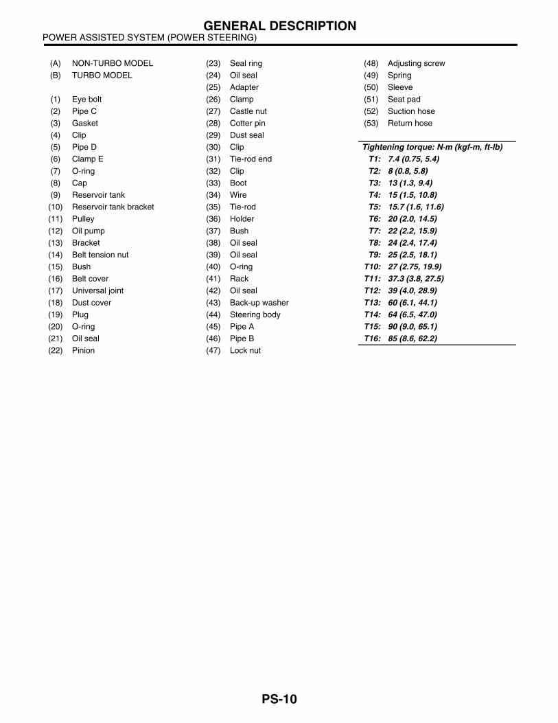
(A) NON-TURBO MODEL (23) Seal ring (48) Adjusting screw
(B) TURBO MODEL (24) Oil seal (49) Spring
(25) Adapter (50) Sleeve
(1) Eye bolt (26) Clamp (51) Seat pad
(2) Pipe C (27) Castle nut (52) Suction hose
(3) Gasket (28) Cotter pin (53) Return hose
(4) Clip (29) Dust seal
(5) Pipe D (30) Clip Tightening torque: N·m (kgf-m, ft-lb)(6) Clamp E (31) Tie-rod end T1: 7.4 (0.75, 5.4)(7) O-ring (32) Clip T2: 8 (0.8, 5.8)(8) Cap (33) Boot T3: 13 (1.3, 9.4)(9) Reservoir tank (34) Wire T4: 15 (1.5, 10.8)
(10) Reservoir tank bracket (35) Tie-rod T5: 15.7 (1.6, 11.6)(11) Pulley (36) Holder T6: 20 (2.0, 14.5)(12) Oil pump (37) Bush T7: 22 (2.2, 15.9)(13) Bracket (38) Oil seal T8: 24 (2.4, 17.4)(14) Belt tension nut (39) Oil seal T9: 25 (2.5, 18.1)(15) Bush (40) O-ring T10: 27 (2.75, 19.9)(16) Belt cover (41) Rack T11: 37.3 (3.8, 27.5)(17) Universal joint (42) Oil seal T12: 39 (4.0, 28.9)(18) Dust cover (43) Back-up washer T13: 60 (6.1, 44.1)(19) Plug (44) Steering body T14: 64 (6.5, 47.0)(20) O-ring (45) Pipe A T15: 90 (9.0, 65.1)(21) Oil seal (46) Pipe B T16: 85 (8.6, 62.2)(22) Pinion (47) Lock nut
PS-10
POWER ASSISTED SYSTEM (POWER STEERING)GENERAL DESCRIPTION
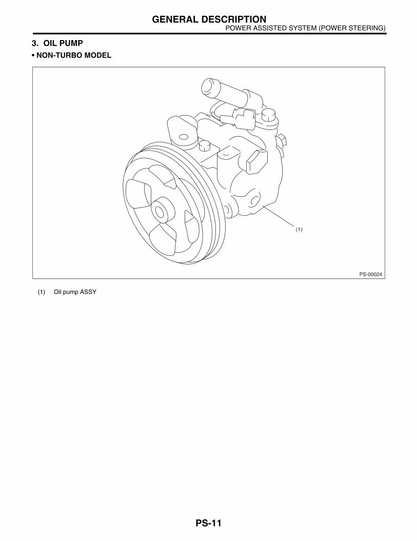
3. OIL PUMP• NON-TURBO MODEL
(1) Oil pump ASSY
PS-00024
(1)
PS-11

POWER ASSISTED SYSTEM (POWER STEERING)GENERAL DESCRIPTION
• TURBO MODEL
(1) Oil pump ASSY
PS-00005
(1)
PS-12

POWER ASSISTED SYSTEM (POWER STEERING)GENERAL DESCRIPTION
C: CAUTION• Wear working clothing, including a cap, protec-tive goggles, and protective shoes during opera-tion.• Before removal, installation or disassembly, besure to clarify the failure. Avoid unnecessary re-moval, installation, disassembly and replacement.• Be careful not to burn your hands, because eachpart on the vehicle is hot after running.• Use SUBARU genuine power steering fluid,grease etc. or the equivalent. Do not mix steeringfluid, grease etc. with that of another grade or fromother manufacturers.• Be sure to tighten fasteners including bolts andnuts to the specified torque.• Place shop jacks or safety stands at the specifiedpoints.• Before securing a part on a vise, place cushion-ing material such as wood blocks, aluminum plate,or shop cloth between the part and the vise.
PS-13

POWER ASSISTED SYSTEM (POWER STEERING)GENERAL DESCRIPTION
D: PREPARATION TOOL1. SPECIAL TOOLS
ILLUSTRATION TOOL NUMBER DESCRIPTION REMARKS
925700000 WRENCH • Used for removing and installing tie-rod.• Apply this tool to rack.
925711000 PRESSURE GAUGE
Used for measuring oil pump pressure.
926200000 STAND Used when inspecting characteristic of gearbox assembly and disassembling it.
34099AC010 ADAPTER HOSE A Used with PRESSURE GAUGE (925711000).
ST-925700000
ST-925711000
ST-926200000
ST34099AC010
PS-14

POWER ASSISTED SYSTEM (POWER STEERING)GENERAL DESCRIPTION
34099AC020 ADAPTER HOSE B Used with PRESSURE GAUGE (925711000).
926230000 SPANNER For the lock nut when adjusting backlash of gear-box.
34099PA100 SPANNER Measurement of rotating resistance of gear-box assembly.
34199AE040 OIL CHARGE GUIDE
Used for charging power steering fluid.
ILLUSTRATION TOOL NUMBER DESCRIPTION REMARKS
ST34099AC020
ST926230000
ST34099PA100
ST34199AE040
PS-15

POWER ASSISTED SYSTEM (POWER STEERING)GENERAL DESCRIPTION
926420000 PLUG When oil leaks from pinion side of gearbox assembly, remove pipe B from valve housing, attach this tool and check oil leaking points.
926370000 INSTALLER A • Used for installing valve assembly into valve housing assembly.• Used with STAND BASE (34099FA100).• For LHD model.
34099FA100 STAND BASE • Used for assembling power steering gearbox.• For LHD model.
926390001 COVER & REMOVER ASSY
• Used for assembling rack assembly.• For LHD model.
ILLUSTRATION TOOL NUMBER DESCRIPTION REMARKS
ST-926420000
ST-926370000
ST34099FA100
ST-926390001
PS-16

POWER ASSISTED SYSTEM (POWER STEERING)GENERAL DESCRIPTION
926400000 GUIDE • Right side of rack when installing rack bush.• Used with GUIDE (927660000).• For LHD model.
927660000 GUIDE • Right side of rack when installing rack bush.• Used with GUIDE (926400000).• For LHD model.
927620000 INSTALLER B • Used for installing oil seal of valve housing.• Used with INSTALLER A (926360000).
926360000 INSTALLER A • Used as a guide to install oil seal.• Used with INSTALLER B (927620000).
ILLUSTRATION TOOL NUMBER DESCRIPTION REMARKS
ST-926400000
ST-927660000
ST-927620000
ST-926360000
PS-17

POWER ASSISTED SYSTEM (POWER STEERING)GENERAL DESCRIPTION
34099FA110 INSTALLER Used for installing oil seal.
34099FA120 INSTALLER AND REMOVER SEAL
• Used for installing valve housing oil seal.• Used with INSTALLER SEAL. (34099FA130)• Used for installing valve housing ball bearing.• Used for removing oil seal and ball bearing from valve housing.
34099FA130 INSTALLER SEAL • Used for installing valve housing oil seal.• Used with INSTALLER AND REMOVER SEAL (34099FA120).
926250000 GUIDE • Used for installing holder ASSY into rack housing.• For RHD model.
ILLUSTRATION TOOL NUMBER DESCRIPTION REMARKS
ST34099FA110
ST34099FA120
ST34099FA130
ST-926250000
PS-18

POWER ASSISTED SYSTEM (POWER STEERING)GENERAL DESCRIPTION
927490000 INSTALLER A, B, C • Used for installing oil seal into rack assembly.• For RHD model.
927580000 REMOVER • Used for removing back-up ring and oil seal.• For RHD model.
34199AE000 GUIDE • Used for installing rack and seal into housing assembly.• For RHD model.
34099FA030 INSTALLER & REMOVER
• Used for removing and installing rack oil seal (outer & inner).• For RHD model.
ILLUSTRATION TOOL NUMBER DESCRIPTION REMARKS
ST-927490000
ST-927580000
ST34199AE000
ST34099FA030
PS-19

POWER ASSISTED SYSTEM (POWER STEERING)GENERAL DESCRIPTION
34199AE010 INSTALLER • Used for installing rack oil seal (outer).• For RHD model.
34099FA060 PUNCH HOLDER • Used for caulking.• For RHD model.
34099FA070 BASE • Used for supporting housing assembly.• For RHD model.
34099FA080 PUNCH • Used for removing caulking.• For RHD model.
ILLUSTRATION TOOL NUMBER DESCRIPTION REMARKS
ST34199AE010
ST34099FA060
ST34099FA070
ST34099FA080
PS-20
POWER ASSISTED SYSTEM (POWER STEERING)GENERAL DESCRIPTION
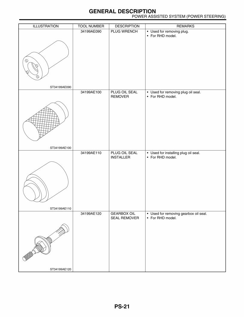
34199AE090 PLUG WRENCH • Used for removing plug.• For RHD model.
34199AE100 PLUG OIL SEAL REMOVER
• Used for removing plug oil seal.• For RHD model.
34199AE110 PLUG OIL SEAL INSTALLER
• Used for installing plug oil seal.• For RHD model.
34199AE120 GEARBOX OIL SEAL REMOVER
• Used for removing gearbox oil seal.• For RHD model.
ILLUSTRATION TOOL NUMBER DESCRIPTION REMARKS
ST34199AE090
ST34199AE100
ST34199AE110
ST34199AE120
PS-21

POWER ASSISTED SYSTEM (POWER STEERING)GENERAL DESCRIPTION
2. GENERAL PURPOSE TOOLS
34199AE130 GEARBOX OIL SEAL INSTALLER
• Used for installing gearbox oil seal.• For RHD model.
TOOL NAME REMARKS
Spring scale Used for measuring tightening torque.
Snap ring pliers Used for removing and installing snap ring.
Dial gauge Used for measuring steering gearbox.
ILLUSTRATION TOOL NUMBER DESCRIPTION REMARKS
ST34199AE130
PS-22

POWER ASSISTED SYSTEM (POWER STEERING)STEERING WHEEL
2. Steering WheelA: REMOVAL1) Disconnect the ground cable from battery.2) Set the tires to straight-ahead position.3) Remove the airbag module.<Ref. to AB-15, RE-MOVAL, Driver's Airbag Module.>
WARNING:Always refer to “AirBag System” before per-forming airbag module service. <Ref. to AB-3,CAUTION, General Description.>4) Make matching marks on the steering wheel andsteering shaft.
5) Remove the steering wheel nut, and then drawout the steering wheel from shaft using steeringpuller.
B: INSTALLATIONWARNING:Always refer to “AirBag System” before per-forming airbag module service. <Ref. to AB-3,CAUTION, General Description.>1) Align the center of roll connector. <Ref. to AB-20, ADJUSTMENT, Roll Connector.>2) Install in the reverse order of removal.
NOTE:Align matching marks on the steering wheel andsteering shaft.
Tightening torque:45 N·m (4.6 kgf-m, 33.2 ft-lb)
Column cover-to-steering wheel clearance:2 — 4 mm (0.08 — 0.16 in)
CAUTION:Insert the roll connector guide pin into guide hole on lower end of surface of steering wheel to prevent damage.
C: INSPECTION1) Check the steering wheel for deformation. If thedeformation is excessive, replace steering wheel.
2) Check the splines on steering wheel for damage.If the damage is excessive, replace steering wheel.
(1) Matching mark
PS-00030
PS-23

POWER ASSISTED SYSTEM (POWER STEERING)UNIVERSAL JOINT
3. Universal JointA: REMOVAL1) Remove the steering wheel. <Ref. to PS-23, RE-MOVAL, Steering Wheel.>2) Make matching mark on the universal joint.3) Remove the universal joint bolts, and then re-move the universal joint.
B: INSTALLATION1) Align the cutout at serrated section of the columnshaft and yoke, and then insert the universal jointinto column shaft.
2) Align the matching marks, and then insert theuniversal joint to serrated section of gear box as-sembly.
3) Tighten the bolt.
Tightening torque:24 N·m (2.4 kgf-m, 17.4 ft-lb)
CAUTION:Excessively large tightening torque of the uni-versal joint bolts may lead to heavy steering wheel operation.
Standard clearance between gearbox to DOJ:Over 14 mm (0.55 in)
4) Align the center of roll connector. <Ref. to AB-20, ADJUSTMENT, Roll Connector.>5) Install the steering wheel and airbag module.<Ref. to PS-23, INSTALLATION, Steering Wheel.>
WARNING:Always refer to “AirBag System” before per-forming airbag module service. <Ref. to AB-3,CAUTION, General Description.>
(1) Cutout
(2) Yoke
(3) Column shaft
(4) Column shaft side
(5) Gearbox side
PS-00031
PS-00032
PS-24

POWER ASSISTED SYSTEM (POWER STEERING)UNIVERSAL JOINT
C: INSPECTIONCheck for wear, damage, or any other faults. If nec-essary, replace.
Service limit:Universal joint play; 0 mm (0 in)Maximum swing torque; 0.3 N (0.03 kgf, 0.07 lb)
Measurement of folding torque of universal joint isas shown in the figures.
Service limit:Maximum load; 3.8 N (0.39 kgf, 0.86 lb) or less
Service limit:Maximum load; 3.8 N (0.39 kgf, 0.86 lb) or less
Service limit:Maximum load; 7.3 N (0.74 kgf, 1.64 lb) or less
Service limit:Maximum load; 7.3 N (0.74 kgf, 1.64 lb) or less
(1) Swing torque
(2) Play
(1) Yoke (gearbox side)
(1) Yoke (gearbox side)
PS-00033
(1)
(2)
PS-00034
PS-00035
(1) Yoke (Steering column side)
(1) Yoke (Steering column side)
PS-00036
PS-00037
PS-25

POWER ASSISTED SYSTEM (POWER STEERING)TILT STEERING COLUMN
4. Tilt Steering ColumnA: REMOVAL
1) Set the vehicle on a lift.2) Disconnect the ground cable from battery.3) Remove the airbag module. <Ref. to AB-15, RE-MOVAL, Driver's Airbag Module.>
WARNING:Always refer to “AirBag System” before per-forming airbag module service. <Ref. to AB-3,CAUTION, General Description.>4) Remove the steering wheel. <Ref. to PS-23, RE-MOVAL, Steering Wheel.>
5) Remove the universal joint. <Ref. to PS-24, RE-MOVAL, Universal Joint.> 6) Remove the trim panel under instrument panel.7) Remove the steering column lower cover.8) Remove all connectors from steering column.
(1) Tilt steering column Tightening torque: N·m (kgf-m, ft-lb)(2) Universal joint T1: 24 (2.4, 17.4)
T2: 25 (2.5, 18.1)
PS-00038
PS-26

POWER ASSISTED SYSTEM (POWER STEERING)TILT STEERING COLUMN
9) Remove the two bolts under instrument panelsecuring steering column.
10) Pull out the steering shaft assembly from holeon toe board.
CAUTION:• Be sure to remove the universal joint beforeremoving steering shaft assembly installingbolts when removing steering shaft assemblyor when lowering it for servicing of other parts.• Do not loosen the tilt lever when the steeringcolumn is not secured to the vehicle.
B: INSTALLATION1) Set the grommet to toe board.
2) Insert the end of steering shaft into toe boardgrommet.3) With the tilt lever secured, tighten the steeringshaft mounting bolts under instrument panel.
Tightening torque:25 N·m (2.5 kgf-m, 18.1 ft-lb)
4) Connect all connectors under instrument panel.5) Connect the airbag system connector at harnessspool.
NOTE:Make sure to apply double lock.6) Install the lower column cover with tilt lever heldin the lowered position.7) Install the universal joint. <Ref. to PS-24, IN-STALLATION, Universal Joint.>8) Align center of roll connector. <Ref. to AB-20,ADJUSTMENT, Roll Connector.>
9) Install the steering wheel. <Ref. to PS-23, IN-STALLATION, Steering Wheel.>
CAUTION:Insert the roll connector guide pin into guide hole on lower end of surface of steering wheel to prevent damage. 10) Install the airbag module to steering wheel.
WARNING:Always refer to “AirBag System” before per-forming the service operation. <Ref. to AB-3,CAUTION, General Description.>
C: DISASSEMBLYRemove the two screws securing upper steeringcolumn covers, and two screws securing combina-tion switch, and then remove the related parts.
D: ASSEMBLY1) Insert the combination switch to upper columnshaft, and then install the upper column cover.Then route the ignition key harness and combina-tion switch harness between column cover mount-ing bosses.
Tightening torque:1.2 N·m (0.12 kgf-m, 0.9 ft-lb)
CAUTION:Do not overtorque the screw.
PS-00040
PS-00041
PS-27

POWER ASSISTED SYSTEM (POWER STEERING)TILT STEERING COLUMN
E: INSPECTION1. BASIC INSPECTIONMeasure overall length of the steering column. Ifnot as specified, replace.
Standard value:Overall length L815.6±±±±1.5 mm (32.11±±±±0.059 in)
2. AIRBAG MODEL INSPECTION
WARNING:For airbag model inspection procedures, referto “AirBag System”. <Ref. to AB-3, CAUTION,General Description.>
PS-00042
L
PS-28

POWER ASSISTED SYSTEM (POWER STEERING)STEERING GEARBOX [LHD MODEL]
5. Steering Gearbox [LHD MOD-EL]
A: REMOVAL1) Set the vehicle on a lift.2) Disconnect the ground cable from battery.3) Loosen the front wheel nut.4) Lift-up the vehicle, and then remove the frontwheels.5) Remove the under cover.6) Remove the sub frame. <Ref. to FS-25, RE-MOVAL, Sub Frame.>7) Remove the front exhaust pipe assembly. (Non-turbo model)<Ref. to EX(SOHC)-7, REMOVAL, Front ExhaustPipe.>
WARNING:Be careful, the exhaust pipe is hot.8) Using a puller, remove the tie-rod end fromknuckle arm after pulling off cotter pin and remov-ing castle nut.
9) Remove the jack-up plate and front stabilizer.
10) Remove the one pipe joint at center of gearbox,and connect vinyl hose to pipe and joint. Dischargefluid by turning the steering wheel fully clockwiseand counterclockwise. Discharge fluid similarlyfrom the other pipe.
11) Remove the universal joint. <Ref. to PS-24,REMOVAL, Universal Joint.> 12) Disconnect the lower pipe C from gear box first,and upper pipe D second.
13) Remove the clamp bolts securing gearbox tocrossmember, and then remove the gearbox.
(1) Castle nut
(2) Tie-rod end
(3) Knuckle arm
(1) Jack-up plate
PS-00043
PS-00044
(1) Pipe A
(2) Pipe B
(1) Pipe C
(2) Pipe D
(1) Clamp
PS-00026
PS-00027
PS-00028
PS-29

POWER ASSISTED SYSTEM (POWER STEERING)STEERING GEARBOX [LHD MODEL]
B: INSTALLATION1) Insert the gearbox into crossmember, beingcareful not to damage the gearbox boot.2) Tighten the gearbox to crossmember bracket viaclamp with bolt to specified torque.
Tightening torque:59 N·m (6.0 kgf-m, 43.4 ft-lb)
3) Connect the pipe D first to gear box, and pipe Csecond.
Tightening torque:T: 15 N·m (1.5 kgf-m, 10.8 ft-lb)
4) Install the universal joint. <Ref. to PS-24, IN-STALLATION, Universal Joint.>5) Connect the tie-rod end and knuckle arm, andtighten with castle nut.
Castle nut tightening torque:27 N·m (2.75 kgf-m, 19.9 ft-lb)
CAUTION:When connecting, do not hit the cap at bottom of tie-rod end with hammer.
6) After tightening the castle nut to specifiedtorque, tighten it further within 60° until cotter pinhole is aligned with the slot in nut, and then bendthe cotter pin to lock.
7) Install the front stabilizer to vehicle. <Ref. to FS-23, INSTALLATION, Front Stabilizer.>8) Install the front exhaust pipe assembly.9) Install the sub frame. <Ref. to FS-25, INSTAL-LATION, Sub Frame.>10) Install the under cover. <Ref. to EI-22, INSTAL-LATION, Front Under Cover.>11) Align the center of roll connector. <Ref. to AB-20, ADJUSTMENT, Roll Connector.>12) Install the steering wheel. <Ref. to PS-23, IN-STALLATION, Steering Wheel.>13) Install the tires.14) Tighten the wheel nuts to specified torque.
Tightening torque:90 N·m (9.1 kgf-m, 65.8 ft-lb)
15) Connect the battery ground cable to battery.16) Pour fluid into the oil tank, and bleed air. <Ref.to PS-89, Power Steering Fluid.>17) Check for fluid leaks.18) Install the jack-up plate.19) Lower the vehicle.20) Check the fluid level in oil tank.21) After adjusting the toe-in and steering angle,tighten the lock nut on tie-rod end.
Tightening torque:83 N·m (8.5 kgf-m, 61.5 ft-lb)
(1) Clamp
(1) Pipe C
(2) Pipe D
PS-00028
PS-00027
(A) Cotter pin
(B) Castle nut
(C) Tie-rod end
DS-00042
PS-30

POWER ASSISTED SYSTEM (POWER STEERING)STEERING GEARBOX [LHD MODEL]
NOTE:When adjusting the toe-in, hold boot as shown toprevent it from being rotated or twisted. If twisted,straighten it.
C: DISASSEMBLY1. RACK HOUSING ASSEMBLY1) Disconnect the four pipes from gearbox.
NOTE:Remove the pipes E and F as a single unit beingfixed at clamp plate.2) Secure the gearbox removed from vehicle invice using ST.ST 926200000 STAND
CAUTION:Secure the gearbox in a vise using ST as shown. Do not attempt to secure it without this ST.
3) Remove the tie-rod end and lock nut from gear-box.
4) Remove the small clip from boot using pliers,and then move the boot to tie-rod end side.
5) Using a flat tip screwdriver, remove the bandfrom boot.
6) Extend the rack approx. 40 mm (1.57 in) out. Un-lock the lock washer on both side of tie-rod end us-ing a flat tip screwdriver.
CAUTION:Be careful not to scratch the rack surface as oil leaks may result.
PS-00051
PS-00029
(1) Clip
(1) Band
(1) Lock washer
(2) Approx. 40 mm (1.57 in)
PS-00048
PS-00082
PS-00091
(2)(1)
PS-31

POWER ASSISTED SYSTEM (POWER STEERING)STEERING GEARBOX [LHD MODEL]
7) Using the ST, loosen the lock nut.ST 926230000 SPANNER
8) Tighten the adjusting screw until it no longertightens.
9) Using a wrench [32 mm (1.26 in) width acrossflats] or adjustable wrench, remove the tie-rod.
10) Loosen the adjusting screw, and then removethe spring and sleeve.11) Remove the two bolts securing valve assem-bly.
12) Carefully draw out the input shaft, and then re-move the valve assembly.
13) Using a sharp pointed pliers, rotate the rackstopper in direction of the arrow until end of the cir-clip comes out of stopper. Rotate the circlip in op-posite direction and pull it out.
14) Pull the rack assembly from cylinder side, anddraw out the rack bushing and rack stopper togeth-er with the rack assembly.
CAUTION:Be careful not to contact the rack to inner wall of cylinder when drawing out. Any scratch on the cylinder inner wall will cause oil leakage.
PS-00089
PS-00109
PS-00110
PS-00116
(1) Rack stopper
(1) Rack bushing
(2) Rack assembly
(3) Rack stopper
PS-00117
PS-00121
PS-00271
(1)
(2)
(3)
PS-32
POWER ASSISTED SYSTEM (POWER STEERING)STEERING GEARBOX [LHD MODEL]
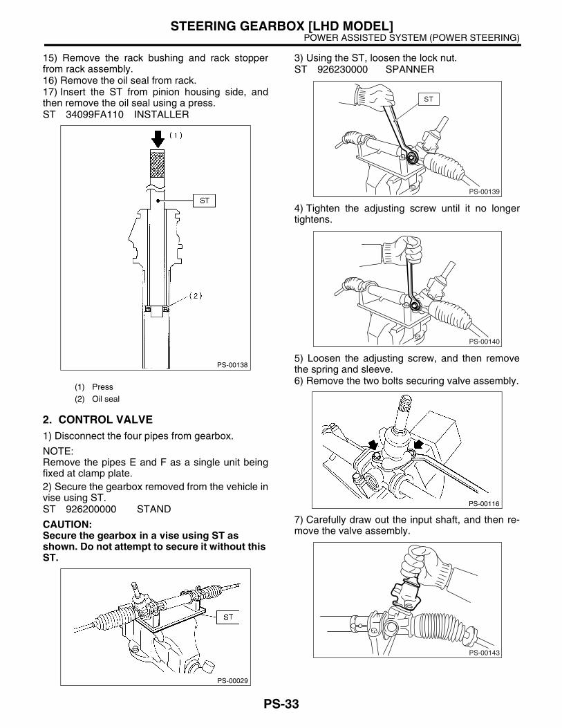
15) Remove the rack bushing and rack stopperfrom rack assembly.16) Remove the oil seal from rack.17) Insert the ST from pinion housing side, andthen remove the oil seal using a press.ST 34099FA110 INSTALLER
2. CONTROL VALVE1) Disconnect the four pipes from gearbox.
NOTE:Remove the pipes E and F as a single unit beingfixed at clamp plate.2) Secure the gearbox removed from the vehicle invise using ST.ST 926200000 STAND
CAUTION:Secure the gearbox in a vise using ST as shown. Do not attempt to secure it without this ST.
3) Using the ST, loosen the lock nut.ST 926230000 SPANNER
4) Tighten the adjusting screw until it no longertightens.
5) Loosen the adjusting screw, and then removethe spring and sleeve.6) Remove the two bolts securing valve assembly.
7) Carefully draw out the input shaft, and then re-move the valve assembly.
(1) Press
(2) Oil seal
PS-00138
PS-00029
PS-00139
ST
PS-00140
PS-00116
PS-00143
PS-33

POWER ASSISTED SYSTEM (POWER STEERING)STEERING GEARBOX [LHD MODEL]
8) Slide the dust cover out.
9) Using a press remove the pinion and valve as-sembly from valve housing.
10) Using the ST and press, remove the dust seal,oil seal and special bearing from valve housing.ST 34099FA120 INSTALLER & REMOVER
SEAL
CAUTION:• Do not apply force to the end surface of valvehousing.• Do not reuse the oil seal after removal.
11) Remove the snap ring using snap ring pliers.
CAUTION:Be careful not to scratch the pinion and valve assembly.
12) Press out the bearing together with the back upwasher using pipe of I.D. 38.5 to 39.5 mm (1.516 to1.555 in) and press.
13) Remove the oil seal.
(1) Dust cover
(1) Valve assembly
(2) Valve housing
(3) Cloth
(1) Oil seal
(2) Special bearing
PS-00144
PS-00149
PS-00150
(1) Bearing
(2) Backing washer
(3) Oil seal
(4) Pipe
PS-00154
PS-00157
PS-34

POWER ASSISTED SYSTEM (POWER STEERING)STEERING GEARBOX [LHD MODEL]
D: ASSEMBLY1. RACK HOUSING ASSEMBLY
CAUTION:Use only SUBARU genuine grease for the gear-box.
Specified grease for gearbox:VALIANT GREASE M2 (Part No. 003608001)
1) Apply power steering fluid to a new oil seal.2) Install the oil seal in correct position as shown inthe figure. Push the oil seal using a press until por-tion A of ST contacts face of B.ST 34099FA110 INSTALLER
CAUTION:Be careful not to damage or scratch the cylin-der inner wall.
3) Fix the rack housing in vise using ST.ST 926200000 STAND
CAUTION:• When fixing the rack housing in vise, be sureto use this special tool. Do not fix rack housingin vise using pad such as aluminum plates, etc.• When using the old rack housing, be sure toclean and remove rust before assembling.Check pinion housing bushing carefully.
4) Fit the ST over toothed portion of rack assembly,and check for binding or unsmooth insertion. If anydeformation is noted on flats at the end of rack,shape by using file, and wash with cleaning fluid.ST 926390001 COVER & REMOVER
5) Apply genuine grease to the teeth of thoroughlywashed rack assembly, and then fit the ST over thetoothed portion.
CAUTION:• Be careful not to block the air passage withgrease. Remove excessive grease.• After fitting cover, check the air passage holefor clogging. If clogged, open by removinggrease from the hole.6) Before inserting the rack assembly, apply a coatof specified power steering fluid to the surfaces ofST and rack piston.7) Insert the rack assembly into rack housing fromcylinder side, and then remove the ST after it haspassed completely through oil seal.8) Fit the ST1 and ST2 over the end of rack, andthen install a new rack bushing.ST1 926400000 GUIDEST2 927660000 GUIDE
(1) Press
(2) Oil seal
PS-00158
(1) Rack assembly
PS-00161
PS-35

POWER ASSISTED SYSTEM (POWER STEERING)STEERING GEARBOX [LHD MODEL]
CAUTION:• If burrs or nicks are found on this guide andrack shaft portion, remove by filing.• Dip the rack bushing in specified powersteering fluid before installing, and pay atten-tion not to damage O-ring and oil seal.
9) Insert the rack stopper into the cylinder tube untilinternal groove (on cylinder side) is aligned with ex-ternal groove (on rack stopper). Turn the rack stop-per with ST so that the rack stopper hole is seenthrough cylinder slits.10) Insert the rack stopper into the rack housing,and then wrap a new circlip using a sharp pointedpliers to secure the rack stopper in position.
CAUTION:Be careful not to scratch the rack while winding circlip.
NOTE:Rotate the wrench another 90 to 180° after end ofcirclip has been wrapped in.
11) Apply genuine grease to dust cover, and theninstall the dust cover to valve assembly.
12) Apply genuine grease to the pinion gear andbearing of valve assembly.
13) Install a new gasket on valve assembly. Insertthe valve assembly into place while facing rackteeth toward pinion.
14) Tighten the bolts alternately to secure valve as-sembly.
Tightening torque:25 N·m (2.5 kgf-m, 18.1 ft-lb)
CAUTION:Be sure to alternately tighten the bolts.15) Temporarily install the rack, and then operate itfrom lock to lock two or three times to make it fit in.Remove the grease blocking air vent hole.
(1) Rack bushing assembly
PS-00162
PS-00163
(1) Dust cover
PS-00164
(1)
PS-00165
PS-00117
PS-36

POWER ASSISTED SYSTEM (POWER STEERING)STEERING GEARBOX [LHD MODEL]
CAUTION:If operating the rack from lock to lock without installing tie-rod, it may damage the oil seal. Al-ways install the tie-rods LH and RH.16) Apply a coat of grease to the sliding surface ofsleeve and seating surface of spring, and then in-sert sleeve into steering body.Charge the adjusting screw with grease, and theninsert the spring into adjusting screw and install onsteering body.
17) Tighten the adjusting screw to specified torque.
Tightening torque:First step; 7.4 N·m (0.75 kgf-m, 5.4 ft-lb)Second step; Back off 25°.°.°.°.
18) Remove the tie-rod.19) Verify that play is within specified value. <Ref.to PS-44, SERVICE LIMIT, INSPECTION, SteeringGearbox [LHD MODEL].>20) Loosen the adjusting screw, and then apply liq-uid gasket to at least 1/3 of the entire perimeter ofadjusting screw thread.
Liquid gasket:THREE BOND 1141
21) Tighten the adjusting screw to specified torque.
Tightening torque:First step; 7.4 N·m (0.75 kgf-m, 5.4 ft-lb)Second step; Back off 25°°°°.
22) Install the lock nut. While holding the adjustingscrew with a wrench, tighten lock nut using ST.ST 926230000 SPANNER
Tightening torque (Lock nut):39 N·m (4.0 kgf-m, 28.9 ft-lb)
NOTE:Hold the adjusting screw with a wrench to prevent itfrom turning while tightening lock nut.23) Extend the rack approx. 40 mm (1.57 in) be-yond side of steering body.24) Install the tie-rod and a new lock washer intorack.
Tightening torque:78 N·m (8.0 kgf-m, 57.9 ft-lb)
25) Bend the lock washer.
(1) Sleeve
(2) Spring
(3) Adjusting screw
(1) Apply liquid gasket to at least 1/3 of entire perimeter.
PS-00167
(2)
(1)
(3)
PS-00092
(1) Tie-rod
(2) Approx. 40 mm (1.57 in)
PS-00091
(2)(1)
PS-37

POWER ASSISTED SYSTEM (POWER STEERING)STEERING GEARBOX [LHD MODEL]
CAUTION:Be careful not to scratch the rack when bending lock washer.
26) Apply a coat of grease to the tie-rod groove,and then install the boot to housing.
NOTE:Make sure that the boot is installed without unusualinflation or deflation.
27) Install a new boot band. Using band clamp pli-ers, caulk the boot band until caulking part clear-ance is 2 mm (0.079 in) or less.
28) Fix the boot end with clip (small).
29) After installing, check the boot end is posi-tioned into groove on tie-rod.
(1) Lock washer
PS-00093
PS-00194
(1) Boot band
(2) 2 mm (0.079 in) or less
(1) Clip
PS-00195
(1)
(2)
PS-00096
PS-38

POWER ASSISTED SYSTEM (POWER STEERING)STEERING GEARBOX [LHD MODEL]
30) If the tie-rod end was removed, screw in thelock nut and tie-rod end to screwed portion of tie-rod, and then tighten the lock nut temporarily in aposition as shown in the figure.
Installed tie-rod length: L31.2 mm (1.23 in)
31) Inspect the gearbox as follows:“A” Holding the tie-rod end, repeat lock to lock twoor three times as quickly as possible.“B” Holding the tie-rod end, turn it slowly at a radiusone or two times as large as possible.After all, make sure that the boot is installed inspecified position without deflation.
32) Remove the gearbox from ST.ST 926200000 STAND33) Install the four pipes on gearbox.
(1) Connect the pipe A and B to four pipe jointsof gearbox.
Tightening torque:13 N·m (1.3 kgf-m, 9.4 ft-lb)(2) Connect the pipe E and F to gearbox.
Tightening torque:Pipe E: 15 N·m (1.5 kgf-m, 10.8 ft-lb)Pipe F: 25 N·m (2.5 kgf-m, 18.1 ft-lb)
2. CONTROL VALVE ASSEMBLY
Specified steering grease:VALIANT GREASE M2 (Part No. 003608001)
1) Clean all parts and tools before reassembling.2) Apply a coat of specified power steering fluid tothe inner wall of valve housing.
3) Attach the ST2 to ST1.ST1 34099FA120 INSTALLER & REMOVER
SEALST2 34099FA130 INSTALLER SEAL4) To avoid scratching the oil seal, apply a coat ofgrease to the contact surface of installer and oilseal.5) Verify the oil seal direction.Attach the oil seal to installer and position in valvehousing before pressing into place.6) Press the oil seal into place using a press.
PS-00097
PS-00098
(1) Apply fluid.
PS-00169(1)
PS-00170
PS-39

POWER ASSISTED SYSTEM (POWER STEERING)STEERING GEARBOX [LHD MODEL]
7) Attach the bearing to ST, and then position invalue housing. Using the ST and press, install thespecial bearing in valve housing.ST 34099FA120 INSTALLER & REMOVER
SEAL
8) Put vinyl tape around the pinion shaft splines toprotect oil seal from damage.9) Fit the pinion and valve assembly into valvehousing.10) Secure the valve assembly to ST1 and ST2.ST1 926370000 INSTALLER AST2 34099FA100 STAND BASE11) Apply specified power steering fluid to oil sealand ST3.
12) Install the ST3 to pinion, and then insert the oilseal. Press the oil seal using a press until ST4 con-tacts face end of valve housing.ST3 926360000 INSTALLER AST4 927620000 INSTALLER B
13) Remove the ST3, and then fit the backingwasher.14) Force-fit the ball bearing using ST3.ST1 926370000 INSTALLER AST2 34099FA100 STAND BASEST3 927640000 INSTALLER B
NOTE:Be careful not to tilt the ball bearing during installa-tion.
(1) Special bearing
(2) Oil seal
PS-00171
(1) Oil seal
(1) Ball bearing
(2) Backing washer
PS-00172
PS-00173
PS-40

POWER ASSISTED SYSTEM (POWER STEERING)STEERING GEARBOX [LHD MODEL]
15) Install the snap ring using snap ring pliers.
NOTE:Rotate the snap ring to check for proper installa-tion.16) Apply the specified grease to dust cover.17) Install the dust cover on valve assembly.
18) Apply genuine grease to the pinion gear andbearing of valve assembly.
19) Install a new gasket on valve assembly. Insertthe valve assembly into place while facing rackteeth toward pinion.
20) Tighten the bolts alternately to secure valve as-sembly.
Tightening torque:25 N·m (2.5 kgf-m, 18.1 ft-lb)
CAUTION:Be sure to alternately tighten the bolts.
21) Apply a coat of grease to the sliding surface ofsleeve and seating surface of spring, and then in-sert sleeve into steering body.Charge the adjusting screw with grease, and theninsert the spring into adjusting screw and install onsteering body.
22) Tighten the adjusting screw to specified torque.
Tightening torque:First step; 7.4 N·m (0.75 kgf-m, 5.4 ft-lb)Second step; Back off 25°.°.°.°.
23) Verify that play is within specified value. <Ref.to PS-44, SERVICE LIMIT, INSPECTION, SteeringGearbox [LHD MODEL].>24) Loosen the adjusting screw, and then apply liq-uid gasket to at least 1/3 of the entire perimeter ofadjusting screw thread.
Liquid gasket:THREE BOND 1141
25) Tighten the adjusting screw to specified torque.
Tightening torque:First step; 7.4 N·m (0.75 kgf-m, 5.4 ft-lb)Second step; Back off 25°°°°.
(1) Dust cover
PS-00164
(1)
PS-00165
PS-00143
(1) Sleeve
(2) Spring
(3) Adjusting screw
(1) Apply liquid gasket to at least 1/3 of entire perimeter.
PS-00167
(2)
(1)
(3)
PS-00092
PS-41

POWER ASSISTED SYSTEM (POWER STEERING)STEERING GEARBOX [LHD MODEL]
26) Install the lock nut. While holding the adjustingscrew with a wrench, tighten lock nut using ST.ST 926230000 SPANNER
Tightening torque (Lock nut):39 N·m (4.0 kgf-m, 28.9 ft-lb)
NOTE:Hold the adjusting screw with a wrench to prevent itfrom turning while tightening lock nut.27) Remove the gearbox from ST.28) Install the four pipes on gearbox.
(1) Connect the pipe A and B to the gearbox.
Tightening torque:13 N·m (1.3 kgf-m, 9.4 ft-lb)(2) Connect the pipe E and F to gearbox.
Tightening torque:Pipe E: 15 N·m (1.5 kgf-m, 10.8 ft-lb)Pipe F: 25 N·m (2.5 kgf-m, 18.1 ft-lb)
PS-42

POWER ASSISTED SYSTEM (POWER STEERING)STEERING GEARBOX [LHD MODEL]
E: INSPECTION1. BASIC INSPECTION1) Clean all disassembled parts, and check for wear, damage, or any other faults, then repair or replace asnecessary.2) When disassembling, check the inside of gearbox for water. If any water is found, carefully check the bootfor damage, input shaft dust seal, adjusting screw and boot clips for poor sealing. If faulty, replace with newparts.
No. Parts Inspection Corrective action
1 Input shaft(1) Bend of input shaft(2) Damage on serration
If the bend or damage is excessive, replace the entire gearbox.
2 Dust seal(1) Crack or damage(2) Wear
If the outer wall slips, the lip is worn out or damage is found, replace it with a new one.
3 Rack and pinion Poor mating of rack with pinion
(1) Adjust the backlash properly. By measuring the turning torque of gearbox and sliding resistance of rack, check if rack and pinion engage uni-formly and smoothly with each other. (Refer to “Service limit”.)(2) Keeping the rack pulled out all the way so that all teeth emerge, check teeth for damage. Even if abnormality is found in either (1) or (2), replace the entire gearbox.
4 Gearbox unit
(1) Bend of rack shaft(2) Bend of cylinder portion(3) Crack or damage on cast iron portion
Replace the gearbox with a new one.
(4) Wear or damage on rack bushIf the free play of rack shaft in radial direction is out of the specified range, replace the gearbox with a new one. (Refer to “Service limit”.)
(5) Wear on input shaft bearingIf the free plays of input shaft in radial and axial directions are out of the specified ranges, replace the gearbox with a new one. (Refer to “Service limit”.)
5 Boot Crack, damage or deterioration Replace.
6 Tie-rod(1) Looseness of ball joint(2) Bend of tie-rod
Replace.
7 Tie-rod endDamage or deterioration on dust seal
Replace.
8Adjusting screw spring
Deterioration Replace.
9 Boot clip Deterioration Replace.
10 Sleeve Damage Replace.
11 Pipes(1) Damage to flared surface(2) Damage to flare nut(3) Damage to pipe
Replace.
PS-43

POWER ASSISTED SYSTEM (POWER STEERING)STEERING GEARBOX [LHD MODEL]
2. SERVICE LIMITMake a measurement as follows. If it exceeds thespecified service limit, adjust or replace.
NOTE:When making a measurement, vise the gearbox byusing ST. Never vise the gearbox by inserting alu-minum plates, etc. between vise and gearbox.ST 926200000 STAND
Sliding resistance of rack shaft:
Service limit400 N (41 kgf, 90 lb) or less
3. RACK SHAFT PLAY IN RADIAL DIREC-TION
Right-turn steering:
Service limit0.19 mm (0.0075 in) or less
On conditionL: 5 mm (0.20 in)P: 122.6 N (12.5 kgf, 27.6 lb)
Left-turn steering:
Service limitDirection
0.3 mm (0.012 in) or lessDirection
0.15 mm (0.0059 in) or less
PS-00099
PS-00100
PS-00101
PS-00102
PS-44

POWER ASSISTED SYSTEM (POWER STEERING)STEERING GEARBOX [LHD MODEL]
4. INPUT SHAFT PLAY
In radial direction:
Service limit0.18 mm (0.0071 in) or less
On conditionP: 98 N (10 kgf, 22 lb)
In axial direction:
Service limit0.5 mm (0.020 in) or less
On conditionP: 20 — 49 N (2 — 5 kgf, 4 — 11 lb)
5. TURNING RESISTANCE OF GEARBOXUsing the ST, measure the gearbox turning resis-tance.ST 34099PA100 SPANNER
Service limitMaximum allowable resistance
10.5 N (1.1 kgf, 2.4 lb) or lessDifference between right and left turning re-sistance: Less than 20 %
PS-00103
PS-00104
PS-00105
PS-45

POWER ASSISTED SYSTEM (POWER STEERING)STEERING GEARBOX [LHD MODEL]
6. OIL LEAKING
1) Even if the location of the leak can be easilyfound by observing the leaking condition, it is nec-essary to thoroughly remove the fluid from the sus-pected portion and turn the steering wheel fromlock to lock about thirty to forty times with enginerunning, then make comparison of the suspectedportion between immediately after and severalhours after this operation.2) Inspect leakage from “a”The oil seal is damaged. Replace the valve assem-bly with a new one.3) Inspect leakage from “b”The torsion bar O-ring is damaged. Replace thevalve assembly with a new one.4) Inspect leakage from “c”The oil seal is damaged. Replace the valve assem-bly or oil seal with a new one.5) Inspect leakage from “d”The pipe is damaged. Replace the faulty pipe or O-ring.6) Inspect leakage from “g”The hose is damaged. Replace the hose with anew one.7) If leak is other than a, b, c, d, or g, and if oil isleaking from the gearbox, move the right and leftboots toward tie-rod end side, respectively, with thegearbox mounted to the vehicle, and remove fluidfrom the surrounding portions. Then, turn the steer-ing wheel from lock to lock thirty to forty times withthe engine running, then make comparison of theleaked portion immediately after and several hoursafter this operation.
(1) Leakage from “e”
The cylinder seal is damaged. Replace the rackbush with a new one.(2) Leakage from “f”There are two possible causes. Take the follow-ing step first. Remove the pipe assembly B fromthe valve housing, and close the circuit with ST.
ST 926420000 PLUGTurn the steering wheel from lock to lock thirty toforty times with the engine running, then makecomparison of the leaked portion between im-mediately after and several hours after this op-eration.
• If leakage from “f” is noted again: The oil seal of pinion and valve assembly is dam-aged. Replace the pinion and valve assembly witha new one. Or replace the oil seal and parts that aredamaged during disassembly with new ones.• If oil stops leaking from “f”: The oil seal of rack housing is damaged. Replacethe oil seal and the parts that are damaged duringdisassembly with new ones.
(1) Power cylinder (3) Rack piston (5) Input shaft
(2) Cylinder (4) Rack axle (6) Valve housing
PS-00272
(4) (3) (2)
(5)
(6)c
d
d
a
b
(1)
de
d
f
gdg
PS-46
POWER ASSISTED SYSTEM (POWER STEERING)STEERING GEARBOX [LHD MODEL]
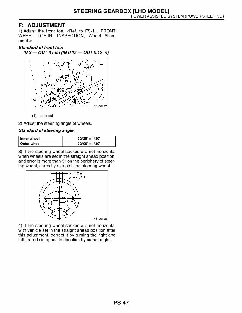
F: ADJUSTMENT1) Adjust the front toe. <Ref. to FS-11, FRONTWHEEL TOE-IN, INSPECTION, Wheel Align-ment.>
Standard of front toe:IN 3 — OUT 3 mm (IN 0.12 — OUT 0.12 in)
2) Adjust the steering angle of wheels.
Standard of steering angle:
3) If the steering wheel spokes are not horizontalwhen wheels are set in the straight ahead position,and error is more than 5° on the periphery of steer-ing wheel, correctly re-install the steering wheel.
4) If the steering wheel spokes are not horizontalwith vehicle set in the straight ahead position afterthis adjustment, correct it by turning the right andleft tie-rods in opposite direction by same angle.
(1) Lock nut
Inner wheel 32°25’ ± 1°30’Outer wheel 32°00’ ± 1°30’
PS-00107
PS-00108
PS-47

POWER ASSISTED SYSTEM (POWER STEERING)STEERING GEARBOX [RHD MODEL]
6. Steering Gearbox [RHD MOD-EL]
A: REMOVAL1) Set the vehicle on a lift.2) Disconnect the ground cable from battery.3) Loosen the front wheel nut.4) Lift-up the vehicle, and then remove the frontwheels.5) Remove the under cover.6) Remove the sub frame.7) Remove the front exhaust pipe assembly. (Non-turbo model) <Ref. to EX(SOHC)-7, REMOVAL,Front Exhaust Pipe.>
WARNING:Be careful, the exhaust pipe is hot.8) Using a puller, remove the tie-rod end fromknuckle arm after pulling off cotter pin and remov-ing castle nut.
9) Remove the jack-up plate and front stabilizer.
10) Remove the one pipe joint at center of gearbox,and connect vinyl hose to pipe and joint. Dischargefluid by turning the steering wheel fully clockwise
and counterclockwise. Discharge fluid similarlyfrom the other pipe.
11) Remove the universal joint. <Ref. to PS-24,REMOVAL, Universal Joint.> 12) Disconnect the lower pipe C from gear box first,and upper pipe D second.
13) Remove the clamp bolts securing gearbox tocrossmember, and then remove the gearbox.
(1) Castle nut
(2) Tie-rod end
(3) Knuckle arm
(1) Jack-up plate
PS-00043
PS-00044
(1) Pipe A
(2) Pipe B
(1) Pipe C
(2) Pipe D
(1) Clamp
PS-00045
PS-00046
PS-00047
PS-48

POWER ASSISTED SYSTEM (POWER STEERING)STEERING GEARBOX [RHD MODEL]
B: INSTALLATION1) Insert the gearbox into crossmember, beingcareful not to damage the gearbox boot.2) Tighten the gearbox to crossmember bracket viaclamp with bolt to specified torque.
Tightening torque:60 N·m (6.1 kgf-m, 44.1 ft-lb)
3) Connect the pipe D first to gear box, and pipe Csecond.
Tightening torque:T: 15 N·m (1.5 kgf-m, 10.8 ft-lb)
4) Install the universal joint. <Ref. to PS-24, IN-STALLATION, Universal Joint.>
5) Connect the tie-rod end and knuckle arm, andtighten with castle nut. Fit the cotter pin into nut,and then bend the pin to lock.
Castle nut tightening torque:27 N·m (2.75 kgf-m, 19.9 ft-lb)
CAUTION:• Tighten to the specified tightening torque,and tighten further within 60°°°° until cotter pinhole is aligned with slot in the nut.• When connecting, do not hit the cap at bot-tom of tie-rod end with hammer.
6) Install the front stabilizer to vehicle.7) Install the front exhaust pipe assembly. 8) Install the sub frame. 9) Install the under cover. 10) Align the center of roll connector. <Ref. to AB-20, ADJUSTMENT, Roll Connector.>11) Install the steering wheel. <Ref. to PS-23, IN-STALLATION, Steering Wheel.>12) Install the tires.13) Tighten the wheel nuts to specified torque.
Tightening torque:90 N·m (9.1 kgf-m, 65.8 ft-lb)
14) Connect the battery ground cable to battery.15) Pour fluid into the oil tank, and bleed air. <Ref.to PS-89, Power Steering Fluid.>16) Check for fluid leaks.17) Install the jack-up plate.18) Lower the vehicle.19) Check the fluid level in oil tank.20) After adjusting the toe-in and steering angle,tighten the lock nut on tie-rod end.
Tightening torque:83 N·m (8.5 kgf-m, 61.5 ft-lb)
(1) Clamp
(1) Pipe C
(2) Pipe D
PS-00047
PS-00049
(A) Cotter pin
(B) Castle nut
(C) Tie-rod
DS-00042
PS-49

POWER ASSISTED SYSTEM (POWER STEERING)STEERING GEARBOX [RHD MODEL]
NOTE:When adjusting the toe-in, hold boot as shown toprevent it from being rotated or twisted. If twisted,straighten it.
C: DISASSEMBLY1) Secure the gearbox removed from vehicle invise using the ST.ST 926200000 STAND
CAUTION:Secure the gearbox assembly in a vise using the ST as shown. Do not attempt to secure it without this ST.
2) Remove the tie-rod end and lock nut from gear-box.3) Remove the clip on outside of boot using pliers,and then slide the boot to tie-rod end side.
4) Using flat tip screwdriver, remove the band fromboot.
NOTE:Check the boot for crack, damage or deterioration.Replace the boot with a new one if necessary.
5) Using the ST, loosen lock nut.ST 926230000 SPANNER
6) Tighten the adjusting screw until it no longertightens.
(1) Clamp
(1) Clip
PS-00051
PS-00052
PS-00053
(1) Band
(1) Lock nut
(1) Adjusting screw
PS-00054
PS-00056
PS-00057
PS-50

POWER ASSISTED SYSTEM (POWER STEERING)STEERING GEARBOX [RHD MODEL]
7) Using a wrench (32 mm width across flats) or ad-justable wrench with cinching boot, remove the tie-rod.
8) Loosen the adjusting screw, and then removethe spring and sleeve.9) Disconnect the pipes A and B from steering bodyand control valve housing.
10) Clean the dirt of input shaft. Remove the dustcover taking care not to scratch the housing or in-put shaft and allow foreign matter to enter gear boxinterior.
11) Align the ST pin to plug hole to install. Rotatethe ST counterclockwise to remove plug.ST 34199AE090 PLUG WRENCH
12) Remove the valve assembly taking care not toscratch seal ring and valve housing inner surface.
(1) Tie-rod
(1) Pipe A
(2) Pipe B
(1) Dust cover
PS-00058
PS-00059
PS-00060
(1) Plug
(1) Valve ASSY
(2) Seal ring
PS-00061
PS-00062
PS-51

POWER ASSISTED SYSTEM (POWER STEERING)STEERING GEARBOX [RHD MODEL]
13) Remove the holder using a wrench (32mmwidth across flats) or adjustable wrench.
14) Install the ST on valve side of rack and pressouter side oil seal out taking care not to contactrack with steering body inner surface.ST 34099FA030 INSTALLER & REMOVER
NOTE:Block the pipe connection of steering body to pre-vent fluid from flowing out.
15) Insert the ST from valve side and press back-up ring and oil seal out.ST 927580000 REMOVER
16) Using the ST1 and ST2, repair the cylinder'sclinched sections.ST1 34099FA080 PUNCHST2 34099FA070 BASE
(1) Rack piston
(2) Outer side oil seal
PS-00063
PS-00064
(1) Cylinder
PS-00065
PS-00066
PS-52

POWER ASSISTED SYSTEM (POWER STEERING)STEERING GEARBOX [RHD MODEL]
17) If the cylinder edge is deformed in a convexshape, repair using an oil stone.
18) Remove the oil seal using ST and press fromplug. ST 34199AE100 PLUG OIL SEAL REMOVER
NOTE:Do not apply force on the plug edge surface.
19) Set the ST on drawing dimension.ST 34199AE120 GEARBOX OIL SEAL RE-
MOVER
20) Set the stopper to gear box, and then insert thetip of ST to gear box.
21) By fixing the 2-surface width, press in by rotat-ing the rod and attach to oil seal.
(1) Oil seal
(2) O-ring
(1) 70 mm (2.76 in)
PS-00067
PS-00068
PS-00069
(1) Stopper
(2) Oil seal
(1) Rod
(2) 2-surface width
PS-00070
PS-00071
PS-53

POWER ASSISTED SYSTEM (POWER STEERING)STEERING GEARBOX [RHD MODEL]
22) While fixing the 2-surface width, pull out the oilseal by rotating nut.
CAUTION:Take care not to scratch the gear box inner sur-face.
D: ASSEMBLY1) Apply a coat of grease to inside and outside ofnew oil seal.
Specified steering grease:VALIANT GREASE M2 (Part No. 003608001)
2) Verify the oil seal direction and installation posi-tion. Using the ST and press, press fit the oil seal togear box.ST 34199AE130 GEARBOX OIL SEAL IN-
STALLER
3) Attach the steering body to ST as shown in thefigure. Apply a coat of grease to needle bearing.ST 926200000 STAND
CAUTION:Ensure the needle bearing is free from defects. If it is faulty, replace the steering body with a new one.
(1) 2-surface width
(2) Nut
PS-00072
(1) Oil seal
(1) Steering body
PS-00073
PS-00074
PS-54

POWER ASSISTED SYSTEM (POWER STEERING)STEERING GEARBOX [RHD MODEL]
4) Using the ST·B and ST·C, attach the oil seal toST·A.ST 927490000 INSTALLER; A, B, C
NOTE:Face the oil seal in direction shown in the figure.
5) Insert the ST·A with oil seal assembled, throughgear side of rack. Remove the oil seal from ST·Anear piston, and then remove the ST·A from rack.
6) Install the back-up ring from gear side of rack.
7) Install the ST on rack and equally apply a thincoat of grease to the rack and ST, then install the oilseal.ST 926250000 GUIDE
CAUTION:Be careful not to scratch the oil seal lips with piston's inner ring section.
8) Apply a coat of grease to the grooves in rack,sliding surface of sleeve and sealing surface of pis-ton. Install the ST on end of steering body cylinder.Then insert the rack into steering body from cylin-der side.ST 34199AE000 GUIDE (Oil seal)
CAUTION:Do not allow grease to block the air vent hole on rack.
(A) Oil seal
(A) Oil seal
(B) Rack
(C) Piston
(1) Oil seal
(2) Back-up ring
(3) Rack
PS-00075
ST AST BST C
(A)
PS-00076
ST A(A)
(B)
(C)
PS-00077PS-00077
(1) Rack piston inner ring
(2) Outer side oil seal
(3) Rack
(1) Cylinder side of steering body
(2) Air vent hole
(3) Oil seal
(4) Rack
PS-00078
PS-00079
PS-55

POWER ASSISTED SYSTEM (POWER STEERING)STEERING GEARBOX [RHD MODEL]
9) Using the press, slowly press the inner side oilseal until distance between ST and end of rack is65 mm (2.56 in).ST 34199AE000 GUIDE (Oil seal)
CAUTION:Ensure the ST's inner wall is free of scratches. Otherwise, it may damage the oil seal during in-stallation.
10) Pass the ST2 and pipe through rack and pressouter side oil seal until ST1 is in contact with ST2using press.ST1 34199AE000 GUIDE (Oil seal)ST2 34199AE010 INSTALLER (Oil seal)
11) Install a new holder to cylinder side of steeringbody.
Tightening torque:64 N·m (6.5 kgf-m, 47.0 ft-lb)
12) Using a press, press the ST until its groove isaligned with end of holder.ST 34099FA030 INSTALLER & REMOVER
(1) Rack piston
(2) Inner side oil seal
(3) Back-up ring
(1) Pipe
(2) Outer side oil seal
PS-00080
PS-00081
(1) Installer guide
(2) Holder
(3) Rack piston
(4) Oil seal
(5) Back-up ring
PS-00063
PS-00083
PS-56

POWER ASSISTED SYSTEM (POWER STEERING)STEERING GEARBOX [RHD MODEL]
13) Using the ST, clinch steering body cylinder at apoint less than 3 mm (0.12 in) from holder.
CAUTION:Be careful not to deform the holder.ST 34099FA060 PUNCH HOLDER
14) Roll the vinyl tape on serration part of valve as-sembly, and then apply grease on the tape surface.
15) Apply a coat of grease on the gear teeth ofvalve assembly, and then attach the valve assem-bly taking care not to scratch oil seal and seal ring.
16) Apply grease on the oil seal circumference, andthen press into the plug using ST and a press. Re-place the plug circumference O-rings with newones.ST 34199AE110 PLUG OIL SEAL INSTALLER
CAUTION:Pay attention to the oil seal direction, and at-taching position.
(A) Holder
(B) 3 mm (0.1 in)
(1) Vinyl tape
PS-00084
(A)
(B)
ST
ST
PS-00085
(1) Seal ring
(2) Oil seal
(1) Plug
(2) O-ring
(3) Oil seal
PS-00086
PS-00087
PS-57

POWER ASSISTED SYSTEM (POWER STEERING)STEERING GEARBOX [RHD MODEL]
17) Using the ST, install plug. ST 34199AE090 PLUG WRENCH
Tightening torque:64 N·m (6.5 kgf-m, 47.0 ft-lb)
18) Install the dust cover. Remove the vinyl tape.
19) Temporarily install the rack, and then operate itfrom lock to lock two or three times to make it fit in.Remove the grease blocking air vent hole.
CAUTION:If operating the rack from lock to lock without installing tie-rod, it may damage the oil seal. Al-ways install the tie-rods LH and RH.
20) Apply a coat of grease to the sliding surface ofseat pad, sleeve and seating surface of spring, andthen insert sleeve into steering body.Charge the adjusting screw with grease, and theninsert the spring into adjusting screw and install onsteering body.
21) Tighten the adjusting screw to specified torque.
Tightening torque:7.4 N·m (0.75 kgf-m, 5.4 ft-lb)
NOTE:Tighten to the specified tightening torque, and thenloosen by 25°.22) Remove the tie-rod.23) Verify that play is within specified value. <Ref.to PS-62, SERVICE LIMIT, INSPECTION, SteeringGearbox [RHD MODEL].>24) Loosen the adjusting screw, and then apply liq-uid gasket to at least 1/3 of the entire perimeter ofadjusting screw thread.
Liquid gasket:THREE BOND 1141
(1) Plug
(1) Dust cover
PS-00088
PS-00060
(1) Seat pad
(2) Sleeve
(3) Spring
(4) Adjusting screw
(5) Lock nut
(1) Apply liquid gasket to at least 1/3 of entire perimeter.
PS-00090
PS-00092
PS-58

POWER ASSISTED SYSTEM (POWER STEERING)STEERING GEARBOX [RHD MODEL]
25) Tighten the adjusting screw.
Tightening torque:7.4 N·m (0.75 kgf-m, 5.4 ft-lb)
NOTE:Tighten to the specified tightening torque, and thenloosen by 25°.26) Install the lock nut. While holding the adjustingscrew with a wrench, tighten lock nut using ST.ST 926230000 SPANNER
Tightening torque (Lock nut):39 N·m (4.0 kgf-m, 28.9 ft-lb)
NOTE:Hold the adjusting screw with a wrench to prevent itfrom turning while tightening lock nut.27) Install the tie-rod into rack.
Tightening torque:90 N·m (9.0 kgf-m, 65.1 ft-lb)
NOTE:Check the mating face of rack and tie-rod forforiegn material, dirt, dust and etc.If required, clean the mating face.28) Apply a coat of grease to the tie-rod groove,and then install the boot to housing.
NOTE:Make sure that the boot is installed without unusualinflation or deflation.
29) Caulk the boot so the space inside boot bandcaulking portion becomes 2 mm (0.08 in) or less.
NOTE:Use a new boot band.
30) Fix the boot end with clip (small).
31) After installing, check the boot end is posi-tioned into groove on tie-rod.
PS-00094
(A) Boot band
(B) Less than 2mm (0.08 in)
(1) Clip
PS-00095
(A)
(B)
PS-00096
PS-59

POWER ASSISTED SYSTEM (POWER STEERING)STEERING GEARBOX [RHD MODEL]
32) If the tie-rod end was removed, screw in thelock nut and tie-rod end to screwed portion of tie-rod, and then tighten the lock nut temporarily in aposition as shown in the figure.
Installed tie-rod length: L31.2 mm (1.23 in)
33) Inspect the gearbox as follows:“A” Holding the tie-rod end, repeat lock to lock twoor three times as quickly as possible.“B” Holding the tie-rod end, turn it slowly at a radiusone or two times as large as possible.After all, make sure that the boot is installed inspecified position without deflation.
34) Remove the gearbox from ST.ST 926200000 STAND
PS-00097
PS-00098
PS-60

POWER ASSISTED SYSTEM (POWER STEERING)STEERING GEARBOX [RHD MODEL]
E: INSPECTION1. BASIC INSPECTION1) Clean all disassembled parts, and check for wear, damage, or any other faults, then repair or replace asnecessary.2) When disassembling, check the inside of gearbox for water. If any water is found, carefully check the bootfor damage, input shaft dust seal, adjusting screw and boot clips for poor sealing. If faulty, replace with newparts.
No. Parts Inspection Corrective action
1 Input shaft(1) Bend of input shaft(2) Damage on serration
If the bend or damage is excessive, replace the entire gearbox.
2 Dust seal(1) Crack or damage(2) Wear
If the outer wall slips, lip is worn out or damage is found, replace it with a new one.
3 Rack and pinion Poor mating of rack with pinion
(1) Adjust the backlash properly. By measuring the turning torque of gearbox and sliding resistance of rack, check if rack and pinion engage uni-formly and smoothly with each other. (Refer to “Service limit”.)(2) Keeping the rack pulled out all the way so that all teeth emerge, check teeth for damage. Even if abnormality is found in either (1) or (2), replace the entire gearbox.
4 Gearbox unit
(1) Bend of rack shaft(2) Bend of cylinder portion(3) Crack or damage on cast iron portion
Replace the gearbox with a new one.
(4) Wear or damage on rack bushIf the free play of rack shaft in radial direction is out of the specified range, replace the gearbox with a new one. (Refer to “Service limit”.)
(5) Wear on input shaft bearingIf the free plays of input shaft in radial and axial directions are out of the specified ranges, replace the gearbox with a new one. (Refer to “Service limit”.)
5 Boot Crack, damage or deterioration Replace with a new one.
6 Tie-rod(1) Looseness of ball joint(2) Bend of tie-rod
Replace with a new one.
7 Tie-rod endDamage or deterioration on dust seal
Replace with a new one.
8Adjusting screw spring
Deterioration Replace with a new one.
9 Boot clip Deterioration Replace with a new one.
10 Sleeve Damage Replace with a new one.
11 Pipes(1) Damage to flared surface(2) Damage to flare nut(3) Damage to pipe
Replace with a new one.
PS-61

POWER ASSISTED SYSTEM (POWER STEERING)STEERING GEARBOX [RHD MODEL]
2. SERVICE LIMITMake a measurement as follows. If it exceeds thespecified service limit, adjust or replace.
NOTE:When making a measurement, vise gearbox by us-ing ST. Never vise the gearbox by inserting alumi-num plates, etc. between vise and gearbox.ST 926200000 STAND
Sliding resistance of rack shaft:
Service limit400 N (41 kgf, 90 lb) or less
3. RACK SHAFT PLAY IN RADIAL DIREC-TION
Left-turn steering:
Service limit0.19 mm (0.0075 in) or less
On conditionL: 5 mm (0.20 in)P: 98 N (10 kgf, 22 lb)
Right-turn steering:
Service limitDirection
0.3 mm (0.012 in) or lessDirection
0.19 mm (0.0075 in) or less
PS-00099
PS-00100
PS-00101
PS-00102
PS-62

POWER ASSISTED SYSTEM (POWER STEERING)STEERING GEARBOX [RHD MODEL]
4. INPUT SHAFT PLAY
In radial direction:
Service limit0.18 mm (0.0071 in) or less
On conditionP: 98 N (10 kgf, 22 lb)
In axial direction:
Service limit0.5 mm (0.020 in) or less
On conditionP: 20 — 49 N (2 — 5 kgf, 4 — 11 lb)
5. TURNING RESISTANCE OF GEARBOXUsing the ST, measure gearbox turning resistance.ST 34099PA100 SPANNER
Service limitMaximum allowable resistance
10.5 N (1.1 kgf, 2.4 lb) or less
Difference between right and left turning resis-tance:
Less than 20%
PS-00103
PS-00104
PS-00105
PS-63
POWER ASSISTED SYSTEM (POWER STEERING)STEERING GEARBOX [RHD MODEL]
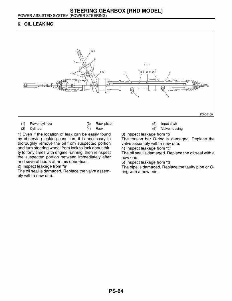
6. OIL LEAKING
1) Even if the location of leak can be easily foundby observing leaking condition, it is necessary tothoroughly remove the oil from suspected portionand turn steering wheel from lock to lock about thir-ty to forty times with engine running, then reinspectthe suspected portion between immediately afterand several hours after this operation.2) Inspect leakage from “a”The oil seal is damaged. Replace the valve assem-bly with a new one.
3) Inspect leakage from “b”The torsion bar O-ring is damaged. Replace thevalve assembly with a new one.4) Inspect leakage from “c”The oil seal is damaged. Replace the oil seal with anew one.5) Inspect leakage from “d”The pipe is damaged. Replace the faulty pipe or O-ring with a new one.
(1) Power cylinder (3) Rack piston (5) Input shaft
(2) Cylinder (4) Rack (6) Valve housing
PS-00106
ab
d c c
d d
PS-64
POWER ASSISTED SYSTEM (POWER STEERING)STEERING GEARBOX [RHD MODEL]
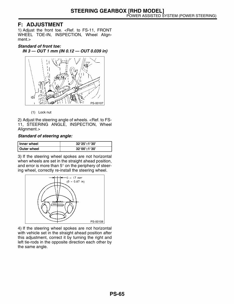
F: ADJUSTMENT1) Adjust the front toe. <Ref. to FS-11, FRONTWHEEL TOE-IN, INSPECTION, Wheel Align-ment.>
Standard of front toe:IN 3 — OUT 1 mm (IN 0.12 — OUT 0.039 in)
2) Adjust the steering angle of wheels. <Ref. to FS-11, STEERING ANGLE, INSPECTION, WheelAlignment.>
Standard of steering angle:
3) If the steering wheel spokes are not horizontalwhen wheels are set in the straight ahead position,and error is more than 5° on the periphery of steer-ing wheel, correctly re-install the steering wheel.
4) If the steering wheel spokes are not horizontalwith vehicle set in the straight ahead position afterthis adjustment, correct it by turning the right andleft tie-rods in the opposite direction each other bythe same angle.
(1) Lock nut
Inner wheel 32°25’±1°30’Outer wheel 32°00’±1°30’
PS-00107
PS-00108
PS-65