power aware cdc verification of dynamic frequency and voltage scaling … · · 2017-12-29power...
TRANSCRIPT
Power Aware CDC Verification of Dynamic Frequency and Voltage
Scaling (DVFS) Artifacts
Mark Handover, Mentor Graphics CorporationJonathan Lovett, Mentor Graphics Corporation
Kurt Takara, Mentor Graphics Corporation
© Accellera Systems Initiative 1
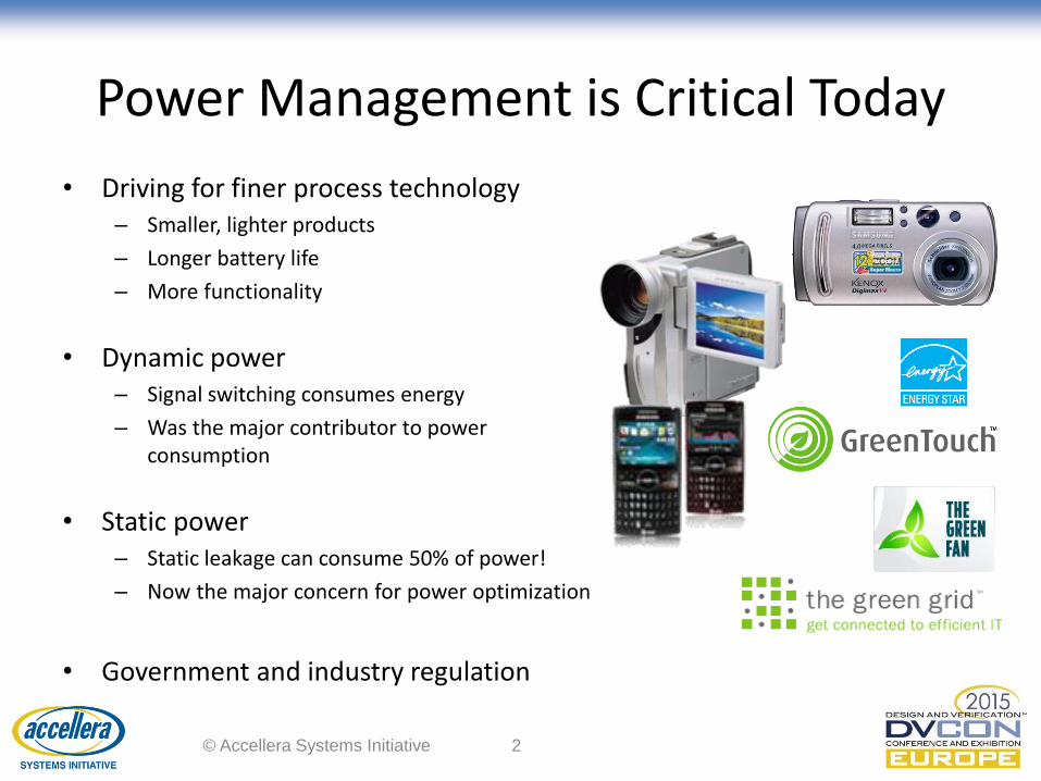
Power Management is Critical Today
• Driving for finer process technology– Smaller, lighter products
– Longer battery life
– More functionality
• Dynamic power– Signal switching consumes energy
– Was the major contributor to power consumption
• Static power– Static leakage can consume 50% of power!
– Now the major concern for power optimization
• Government and industry regulation
© Accellera Systems Initiative 2
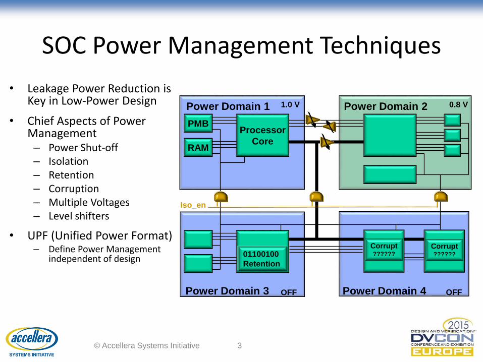
SOC Power Management Techniques
• Leakage Power Reduction is Key in Low-Power Design
• Chief Aspects of Power Management– Power Shut-off– Isolation– Retention– Corruption– Multiple Voltages – Level shifters
• UPF (Unified Power Format)– Define Power Management
independent of design
PMBProcessor
CoreRAM
Power Domain 1 Power Domain 2
Power Domain 3 Power Domain 4
Iso_en
01100100
Retention
Corrupt??????
1.0 V 0.8 V
OFF OFF
© Accellera Systems Initiative 3
Corrupt??????

IEEE 1801 Unified Power Format (UPF)
© Accellera Systems Initiative 4
IP Provider:• Creates IP source
• Creates low power
implementation
constraints
IP Licensee/User:• Configures IP for context
• Validates configuration
• Freezes “Golden Source”
• Implements configuration
• Verifies implementation
against “Golden Source”
RTL
Constraint
UPF
+Configuration
UPF
+
Implementation
UPF
+
Implementation
UPF
Implementation
UPF
Sim
ula
tio
n, L
ogi
cal E
qu
ival
ence
Ch
ecki
ng,
…
Netlist
Synthesis
Netlist
P&R
Soft IP Golden Source
IP Creation1 IP Configuration2 IP Implementation3
RTLConstraint
UPF
RTLConstraint
Configuration
UPF
© 2013 ARM Ltd

Tx Rx
Pwr_ctrl
top
in1
clk1
in2
clk2
out1
Iso_en
clk1
CDC Paths without UPF
• Power control logic unconnected in RTL
• CDC analysis on RTL will not verify power control logic
– RTL functional paths only
© Accellera Systems Initiative 5
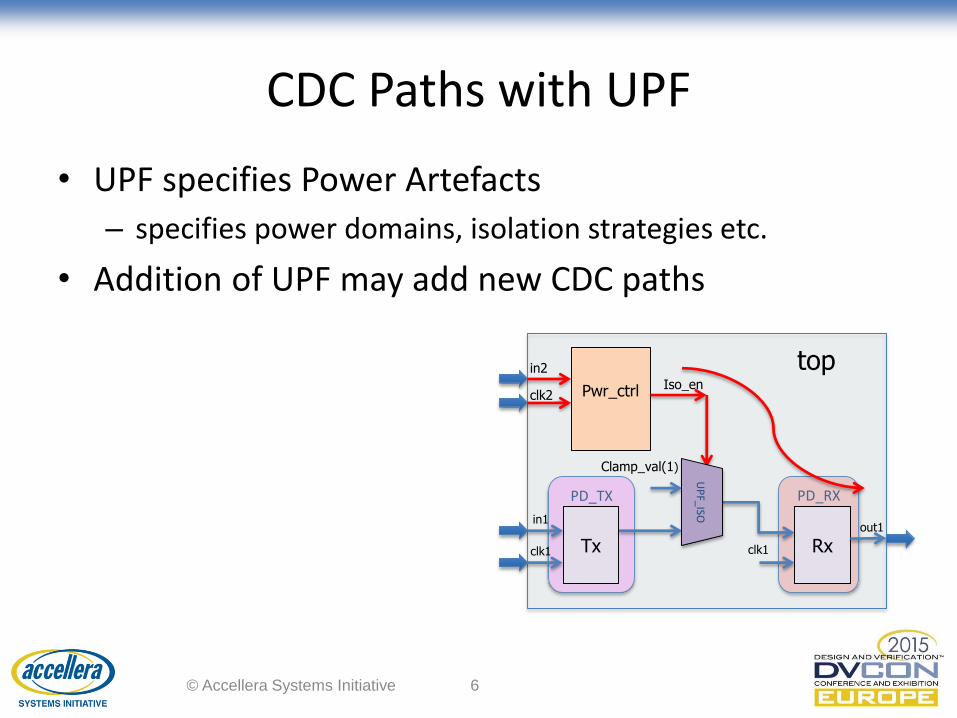
CDC Paths with UPF
• UPF specifies Power Artefacts
– specifies power domains, isolation strategies etc.
• Addition of UPF may add new CDC paths
© Accellera Systems Initiative 6
PD_RXPD_TX
Tx Rx
Pwr_ctrl
top
in1
clk1
in2
clk2
out1
Iso_en
Clamp_val(1)
UP
F_ISO
clk1

• Frequency and Voltage interdependence
– Max operating frequency dependent on voltage
– Reducing frequency allows voltage & power reduction
• Small voltage reductions = large power savings
– Energy consumption proportional to supply voltage
Processor E α V2 *
Dynamic Frequency and Voltage Scaling
* Burd, T. D. and Brodersen, R. W. Energy efficient CMOS microprocessor design. HICSS 1995.
© Accellera Systems Initiative 7

Voltage Domain Crossing (VDC)
• DVFS domains create asynchronous clock groups
• Identify crossings between synchronous paths on different voltage domains
PD_RXPD_TX
Tx Rx
clk1
GND1VDD1 GND2VDD2
© Accellera Systems Initiative 8
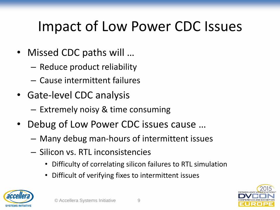
Impact of Low Power CDC Issues
• Missed CDC paths will …
– Reduce product reliability
– Cause intermittent failures
• Gate-level CDC analysis
– Extremely noisy & time consuming
• Debug of Low Power CDC issues cause …
– Many debug man-hours of intermittent issues
– Silicon vs. RTL inconsistencies• Difficulty of correlating silicon failures to RTL simulation
• Difficult of verifying fixes to intermittent issues
© Accellera Systems Initiative 9
Low Power CDC Verification Challenges
© Accellera Systems Initiative 10

UPF Support Requirements for CDC Analysis
• Infer power cells in RTL
– Isolation
– Retention
– Level shifters
• Infer voltage supply network
– Power network
– Power switches
© Accellera Systems Initiative 11

Power Aware CDC Requirement
• Verify interaction between power network and RTL
– UPF specifies power domains, placement of isolation cells
set_design_top topcreate_power_domain TOPcreate_power_domain PD_TX -elements {Tx}create_power_domain PD_RX -elements {Rx}
create_supply_set PRIMARY1 create_supply_set PRIMARY2
associate_supply_set PRIMARY1 -handle PD_TX.primaryassociate_supply_set PRIMARY2 -handle PD_RX.primary
set_isolation PD_TX_ISO_OUT -domain PD_TX \-clamp_value 1 -applies_to outputs \-isolation_signal iso_en -isolation_sense low \-location parent Tx Rx
Pwr_ctrl
top
in1
clk1
in2
clk2
out1
Iso_en
clk1
© Accellera Systems Initiative 12

PD_RXPD_TX
Power Aware CDC Analysis
• Annotated design netlist contains power network
• CDC analysis on RTL + power network
Violations=========================================Isolation enable signal does not have proper synchronizer. (iso_en_no_sync)-----------------------------------------------------------------clk2 : start : Pwr_ctrl.out1
clk1 : end : Rx.out1(ID: iso_en_no_sync_40515)via : qspa_iso_1.out1_UPF_ISO.isolation_signalvia : qspa_iso_1.out1_UPF_ISO.isolation_output
Tx Rx
Pwr_ctrl
top
in1
clk1
in2
clk2
out1
Iso_en
Clamp_val(1)
UP
F_ISO
© Accellera Systems Initiative 13
clk1

Isolation Enable Missing Synchronizer
• Blocks B1 & B2 are in clock clk1
• iso_en comes from block B3 in clock domain clk2
• Violation for the new CDC path B3->B2
ISOclk1
clk2
clk1
B3
B2B1
iso_en
© Accellera Systems Initiative 14
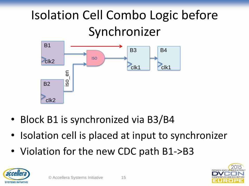
Isolation Cell Combo Logic before Synchronizer
• Block B1 is synchronized via B3/B4
• Isolation cell is placed at input to synchronizer
• Violation for the new CDC path B1->B3
ISOclk2
clk1
B1B3
iso_en
clk2
B2
clk1
B4
© Accellera Systems Initiative 15
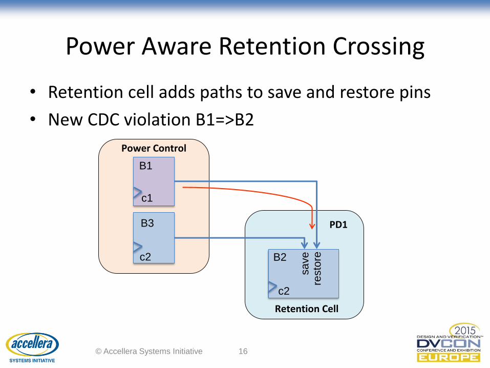
Power Aware Retention Crossing
• Retention cell adds paths to save and restore pins
• New CDC violation B1=>B2
Retention Cell
c2
save
resto
reB2
PD1
c1
B1
c2
Power Control
© Accellera Systems Initiative 16
B3
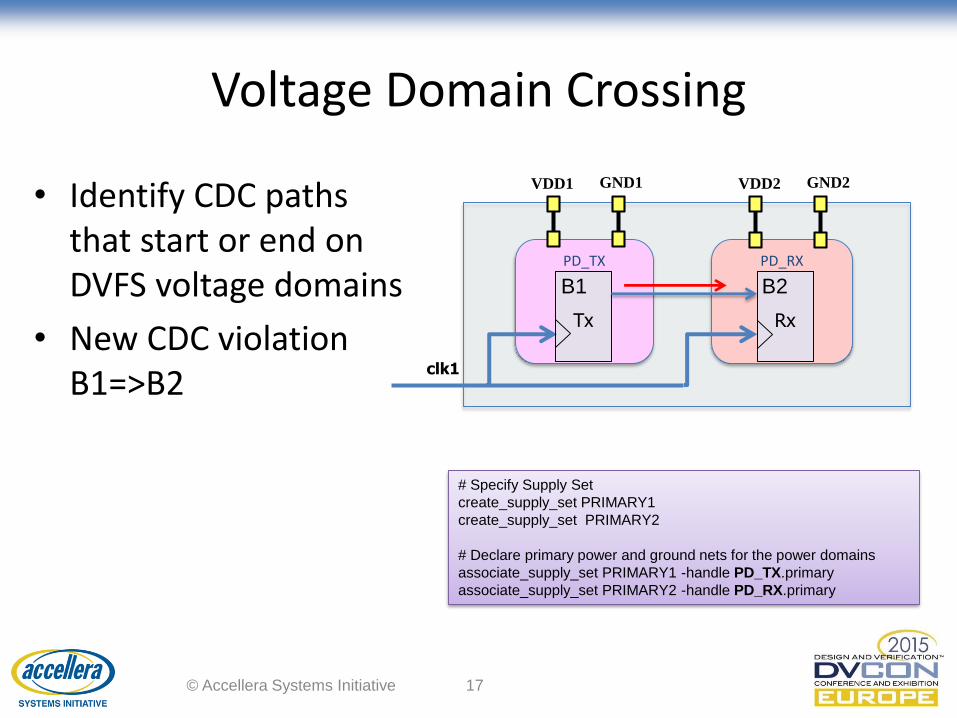
Voltage Domain Crossing
• Identify CDC paths that start or end on DVFS voltage domains
• New CDC violation B1=>B2
PD_RXPD_TX
Tx Rx
clk1
GND1VDD1 GND2VDD2
B1 B2
© Accellera Systems Initiative 17
# Specify Supply Set
create_supply_set PRIMARY1
create_supply_set PRIMARY2
# Declare primary power and ground nets for the power domains
associate_supply_set PRIMARY1 -handle PD_TX.primary
associate_supply_set PRIMARY2 -handle PD_RX.primary
Power Aware CDC with Questa CDC
© Accellera Systems Initiative 18
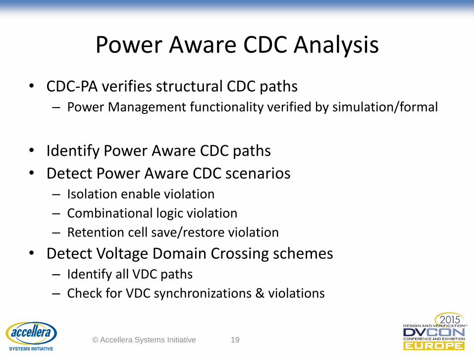
Power Aware CDC Analysis
• CDC-PA verifies structural CDC paths– Power Management functionality verified by simulation/formal
• Identify Power Aware CDC paths
• Detect Power Aware CDC scenarios– Isolation enable violation
– Combinational logic violation
– Retention cell save/restore violation
• Detect Voltage Domain Crossing schemes– Identify all VDC paths
– Check for VDC synchronizations & violations
© Accellera Systems Initiative 19

Power Aware CDC Flow
© Accellera Systems Initiative 20
HDL Logic
Design
HDL
Compilation
Power
AnnotationUPFCDC Analysis
Review &
Debug

Power Aware CDC Reporting & Debug
• Report new voltage domain clock groups
© Accellera Systems Initiative 21
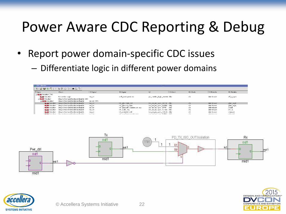
Power Aware CDC Reporting & Debug
• Report power domain-specific CDC issues
– Differentiate logic in different power domains
© Accellera Systems Initiative 22
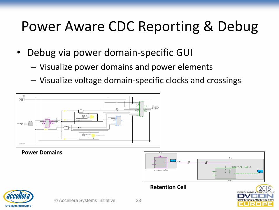
Power Aware CDC Reporting & Debug
• Debug via power domain-specific GUI
– Visualize power domains and power elements
– Visualize voltage domain-specific clocks and crossings
© Accellera Systems Initiative 23
Retention Cell
Power Domains
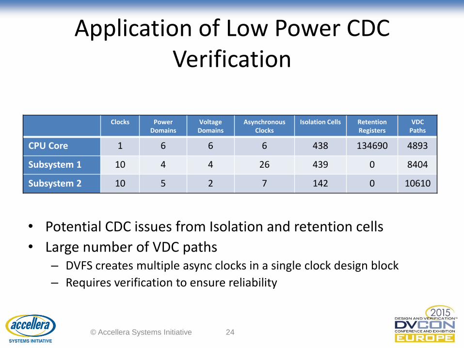
Application of Low Power CDC Verification
Clocks Power Domains
Voltage Domains
AsynchronousClocks
Isolation Cells Retention Registers
VDC Paths
CPU Core 1 6 6 6 438 134690 4893
Subsystem 1 10 4 4 26 439 0 8404
Subsystem 2 10 5 2 7 142 0 10610
© Accellera Systems Initiative 24
• Potential CDC issues from Isolation and retention cells
• Large number of VDC paths– DVFS creates multiple async clocks in a single clock design block
– Requires verification to ensure reliability
Conclusion
• Low Power issues are missed by traditional CDC methods
• Low Power design introduces
– New asynchronous clock domains
– New CDC & VDC paths
• Use Questa Power Aware CDC solution to
– Improve low power design reliability
– Avoid low power CDC failures in silicon
© Accellera Systems Initiative 25

Questions
© Accellera Systems Initiative 26