power flow regulation by use of upfc’s injection modelndizdar/bpt99.pdf · reactive shunt...
TRANSCRIPT

Power flow regulation by use of UPFC’s injection model
N. Dizdarevic, Student Member, IEEE S. Tesnjak, Member, IEEE G. Andersson, Fellow, IEEE Faculty of Electrical Engineering and Computing The Royal Institute of Technology
University of Zagreb, Unska 3, HR-10000 Zagreb, Croatia S-100 44 Stockholm, Sweden
Abstract - The main purpose of this paper is toinvestigate power flow regulating capabilities of anUPFC’s injection model by using all three UPFC’scontrol parameters simultaneously. The control systemof the model is developed and its contributions topower flow regulation are explored on a multi-machinetest system. The analysis is carried out from dynamicaspect utilising time-domain simulations. With theUPFC being embedded in the system, the analysis isconcentrated on a transmission system compensationissues. It is shown that the model can fulfil functions ofreactive shunt compensation, series compensation andphase shifting meeting multiple control objectives byapplying boosting transformer injected voltage andexciting transformer reactive current.
Keywords: FACTS-devices, Unified Power FlowController (UPFC), injection model, power flowregulation, series and shunt compensation, phase shifting
I. INTRODUCTION
The rapid development of power electronics has made itpossible to design power electronic equipment of highrating for high voltage systems. Many regulation problemsresulting from transmission system may be, at least partly,improved by use of the equipment well known as FACTS-controllers. The de-regulation (restructuring) of powernetworks will probably imply new loading conditions andnew power flow situations. This is an additional reason toface the FACTS. In order to deal with the power flowregulation problem, the solutions with FACTS-devicesmust provide mathematical and computer models of thecontrollers. This is considered to be rather new impetus inthe field [1-3].
Within this paper, which is on the trace of our previousworks [4-6], the impact of the Unified Power FlowController (UPFC) on power flow regulation is analysedwithin dynamic approach. Formulation of the problemfrom a transmission system compensation viewpoint is
Paper BPT99-367-12 accepted for presentation at theIEEE Power Tech ’99 Conference, Budapest, Hungary,Aug 29 Sept 2, 1999
well-established [7] and it is used here in a quitestraightforward manner. The UPFC in its general form canprovide simultaneous, real-time control of all basic powersystem parameters (transmission voltage, impedance andphase angle) and dynamic compensation of ac system.Thereby, it can fulfil functions of reactive shuntcompensation, series compensation and phase shiftingmeeting multiple control objectives by applying boostingtransformer injected voltage and exciting transformerreactive current. Besides the power flow regulation, it isuseful in oscillations damping, and in supporting voltagemagnitudes, helping the voltage unstable situations solved.
II. SYSTEM MODELLING
The benefits of the UPFC and its injection model withseveral types of control strategies contributing totransmission system compensation problem are exploredby analysing a simple 6-machine, 20(22)-bus test systemwith 400 kV nominal voltage (Fig. 1). The system is basedon a one often used in CIGRE reports. It is comprised ofsix generators located in two areas, which are modelled byusing two-axis E’ model [8]. The transient effects areaccounted for, while the subtransient ones are neglected.The generators are equipped with excitation systemincluding overexcitation limiter (OEL) and speed governor- turbine system and are connected via interties. The loadsare located in both of the two main areas and are of theZIP type (constant current in active power and constantimpedance in reactive one). The UPFC, in the middle ofone of the interties carrying a fraction of the total powertransmission, is aimed to control the power flow on theintertie in the steady state. The task is considered to betypical in attempt of removing a constraint that limits thepossible power transfer between the areas.
Fig. 1. Multi-machine test system

III. THE UPFC’s INJECTION MODEL
The UPFC (Fig. 2) can provide simultaneous control ofall basic power system parameters (transmission voltage,impedance and phase angle) and dynamic compensation ofac system. The controller can fulfil functions of reactiveshunt compensation, series compensation and phaseshifting meeting multiple control objectives by applyingboosting transformer injected voltage and excitingtransformer reactive current (Figs. 3, 4). The UPFC’sinjection model [9, 10] is used enabling three parametersto be simultaneously controlled (Fig. 5), namely the shuntreactive power, Qconv1, and the magnitude, r, and angle, γ,of the injected series voltage. The control system [4, 5, 6]is of decoupled single-input single-output type. Theselection of input/output signals depends on thepredetermined control mode, which could be changedduring the simulation. At external level, following locallymeasured variables of the UPFC are controlled: the shuntside bus voltage magnitude, Vi, (by changing Qconv1), theseries side bus voltage magnitude, Vj, reactive power flowinto series side bus, Qj, reactive power requirement of theseries side converter 2, Qconv2, or compensating voltagemagnitude, Vcomp, (by changing r) and active power flowinto the series side bus, Pj, active power requirement of theseries side converter 2, Pconv2, bus voltage angle difference,Θij, or compensating voltage angle, ϕcomp, (by changing γ).
Fig. 2. The UPFC device circuit arrangement
Fig. 3. The UPFC electric circuit arrangement
Fig. 4. The UPFC vector diagram
Fig. 5. The UPFC injection model with control
In the model, the shunt side could be controlled only involtage mode Vi↔Qconv1 emphasising that Qconv1represents reactive power loading of the shunt converter 1.The series side could be controlled through the r⇔γ pair inseveral different modes: bus voltage and active power flowVj⇔Pj, reactive and active power flow Qj⇔Pj, seriescompensation Qconv2⇔Pconv2(=0), phase shifting of PhaseAngle Regulator (PAR) type Vj(=Vi)⇔Θij, and phaseshifting of Quadrature Boosting Transformer (QBT) typeVcomp⇔ϕ comp(=π/2). The variables are chosen satisfyinggeneral V↔Q and Θ↔P decoupling. The internal levelcontrol provides fast response converter regulation. A. Transmission voltage support
Bus voltage magnitudes could be supported at bothsides of the UPFC. At the series side, voltage Vj issupported through r-loop with appropriate adjustment ofangle γ. At the shunt side, Vi-feedback enables supportthrough Qconv1-loop. If losses are neglected, the activepower requirement is equal for both converters
( )( )
P P V I
rb VV rb V
conv conv S ij
S i j ij S i
1 2
2
= = =
= − + +
Re
sin sin .
*
θ γ γ(1)
Thereby, the nominal rating Sconv1n of the shunt converter 1is given as a maximum active power demanded by injectedseries voltage source max Pconv1(r,γ)
( )S P rconv n conv1 1= max , .γ (2)Since this MVA capacity is not always fully utilised, thereusually remains some capacity available for producingreactive power and thereby for controlling the voltage Vi.Thus, during the simulation it is necessary to check formaximum available reactive capacity max Qconv1 max ( , ) .Q S P rconv conv n conv1 1
21
2= − γ (3)It is possible to allow a short-term overload capability, butmostly reactive power Qconv1 is in the range− ≤ ≤ +max max .Q Q Qconv conv conv1 1 1 (4)The impact of the Qconv1 comes through the reactive powerQSi of the injection model (Fig. 5)Q rb V QSi S i conv= − +2
1cos .γ (5)By setting appropriate Vi-feedback control in an SVGmanner, the Qconv1 could keep Vi at a referent valuewhenever there is enough remaining reactive capacity inshunt converter.
B. Series compensation
Series compensation mode of the UPFC could beattained by setting angle γ in a position that givesγ π ϕ= −/ 2 , (6)where the angles are defined as in Fig. 4. In that case, thevectors VS and Vcomp are co-linear, and perpendicular to the
current Iij . Therefore, the following relation holds
( )V Vi j ijsin sinγ γ= +Θ , (7)
which makes Pconv2 from (1) equal to zero. It comes outthat for γ regulation keeping Pconv2 at zero enablescharacteristic (V⇔I) perpendicular form of the vectordiagram. The current Iij is generally defined as
( ) ( )[ ]I V V jx P jQ Vij i j S conv conv S= − = +' */ /2 2 , (8)
but this expression is not very convenient due to divisionby r (VS = r Vi ) which could take zero value. To be used inthe series compensation mode only, the following relationis applied instead
( )( )[ ]
I P Q Q V
arc tg Q Q Pij i i conv i
i i conv i
= + −
= + − −
12
1 12
1 1 1
/ ;
/ .ϕ Θ(9)
Equation (9) enables VS magnitude consideration, sinceV V jx IS comp S ij= + . (10)
Multiplying (10) by Iij*, it results with
V I V I jx IS ij comp ij S ij* *
= + 2 . (11)Using proportionality factor kc
( )k V x Ic comp S ij= / , (12)due to zeroed Pconv2, equation (11) becomes jQ jk x I jx Iconv c S ij S ij2
2 2= + , (13)which could be written more conveniently as( )1 02
2+ − =k x I Qc S ij conv . (14)Using (14) in the r-loop, it is enabled to adjust voltagemagnitude Vcomp by setting kc at appropriate value. If kc isset to zero, then VS=xSIij , and Θi=Θj, making reactancebetween buses i and j totally compensated. Having kc<0(kc>0), the total reactance between buses i and j is made tobe inductive ( capacitive) with respect to current Iij.
C. Phase shifting
Phase shifting mode of the UPFC could be achievedoperating it either as a phase angle regulator (PAR) or aquadrature boosting transformer (QBT).
In PAR operation, the bus voltage magnitudes Vi and Vjshould be set equal. It is done in the r-loop by settingV Vi j− = 0 . (15)Then, the bus voltage angle difference Θij = Θi - Θj is set atpredetermined value ΘijREF through γ-loop. By changingreferent value ΘijREF the PAR phase shifting is carried out.
In QBT operation, the voltage Vcomp should be set
perpendicular to the bus voltage Vi , so as the angle γ is setat the position defined byϕ ϕ ϕ π πcomp
REFcomp comp
REF or− = =0 2 3 2; / / . (16)
Following relations concerning Vcomp should be satisfied
( )[ ]( ) ( )
V V V VV
arc V V V
for for
comp i j i j ij
comp j ij i comp
ij comp comp ij comp comp
= + −
= −
≤ ⇒ = > ⇒ = −
2 2 2
0 0 2
cos ;
cos cos / ;
; .
'
' '
Θ
Θ
Θ Θ
ϕ
ϕ ϕ ϕ π ϕ
(17)

D. Damping of electromechanical oscillations
Besides the regulators, the model allowsimplementation of strategy for damping ofelectromechanical oscillations. The strategy is of take-overtype and based on a transient energy function (TEF) [10],using time derivatives of local variables from both sides ofthe UPFC. The shunt part of transient energy functionblock uses information from dVi/dt, whereas the series partfrom dΘij/dt. The control laws for both parts are given in[4-6] with detailed results.
IV. NUMERICAL RESULTS
Determination of operating region in terms ofcharacteristic voltages and power flows could be initiatedby simple two-parameter rotational change of additionalvoltage vector SV . Starting from a point defined byr=rmax=0.15 pu and γ=0°, the change comprises rotation ofthe vector from γ=0° to γ=360°, keeping its magnitudeconstant. Having one period completed, the magnitude isdecreased and the change in the angle γ is started all overagain. Eventually, the magnitude is decreased to minimum(r=0 pu). Dependence of shunt and series side bus voltagemagnitudes, Vi and Vj , with respect to changes in (r, γ)pair is depicted in Fig. 6 (the third parameter, Qconv1 , andthereby Vi , is not controlled in this case). It is shown thatthe voltage magnitudes have opposite changes, i.e. sinceneither of the buses is voltage controlled, one of themcould have magnitude increased if the other one isdecreased and vice versa. Similar effect could be found intransformer operation in a network with low level of short-circuit capacity. The distortion becomes more pronouncedwhenever larger values are given to parameter r. The samecase of the (r, γ) change is also shown in Fig. 7, but in Vj =f (Pj2) domain showing voltage Vj dependence on activepower flow Pj2 at the series side of UPFC. As it could beseen, it would be necessary to have the operating regionvoltage limited due to low magnitude value. In addition,the latter diagram shows the range of active power flow Pj2that could be achieved within the change.
Once having the operating region defined, it isnecessary to adjust parameters of the PI regulator beforeencountering regulation problem. An example (Figs. 8-10)is provided with Vj⇔Pj2 mode of regulation. Starting fromthe UPFC’s operating point 0 (r=rmax, γ=0°), by choosingappropriate values of the parameters, it is made possible tomove operating point through all four quadrants(0→1→2→3→4→1). The point is always kept insideallowed boundaries defined by rmax . The path is obtainedby applying step-change in one variable while keeping theother one constant (the values of Vj are 0.91 pu and 0.95pu, and of Pj2 are –1.75 pu and –2.75 pu). It ends at point1. Besides depicting it in two dimensions (Fig. 8), the samecase could be shown in three dimensions (Figs. 9-10), withdependence of (r, γ) pair respectively to (Vj, Pj2) domain.Thereby, the γ-dependence has a spiral form, whereas the
r-dependence has a conical one. The operating point isfound at the surface of the bodies.
Fig. 6. Vi = f (r, γ) and Vj = f (r, γ) during rotational change
Fig. 7. Vj = f (Pj2 ) dependence during rotational change
Fig. 8. Vj = f (Pj2) dependence during step-changes
Fig. 9. γ = f (Pj2, Vj) dependence during step-changes
Fig. 10. r = f (Pj2, Vj) dependence during step-changes
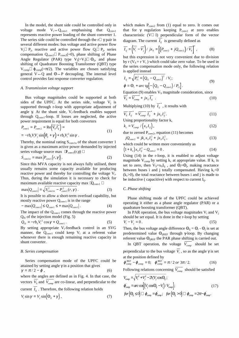
Simultaneous control of all three UPFC’s parameters,(r, γ, Qconv1), enables its operation in several differentmodes of regulation.
In the power flow mode with the shunt-side voltagesupported, it is possible to control reactive, Qj2, and active,Pj2, power flow at the series-side with the voltagemagnitude Vi at the shunt-side simultaneously controlled(Figs. 11-12). After initial steady-state period, defined withr=0 pu, γ=0°, and Vi being uncontrolled, a sequence ofsteps is implemented to show that the power flow (Qj2, Pj2)could be changed in steps and in the same time the voltagemagnitude Vi kept constant at initial value. Thus, the firststep is defined to bring the point to (Qj2, Pj2, Vi) =(-0.5 pu,-3.5 pu, 0.9516 pu) through (r, γ, Qconv1) feedback. Havingthis point achieved, the step back follows to bring the pointat the initial state (-1.01 pu, -2.93 pu, 0.9516 pu). Step 2forces the point to move in different direction (-1.5 pu, -2.5 pu, 0.9516 pu). The ending step brings the point toinitial value. The time responses meet general controlcriteria showing that the control system parameters areappropriately tuned. Moreover, it is shown that in additionto the UPFC’s conventional power flow regulation (Qj2,Pj2), it is also possible to control bus voltage magnitude VIwhenever there is enough remaining reactive capacity ofthe shunt converter.
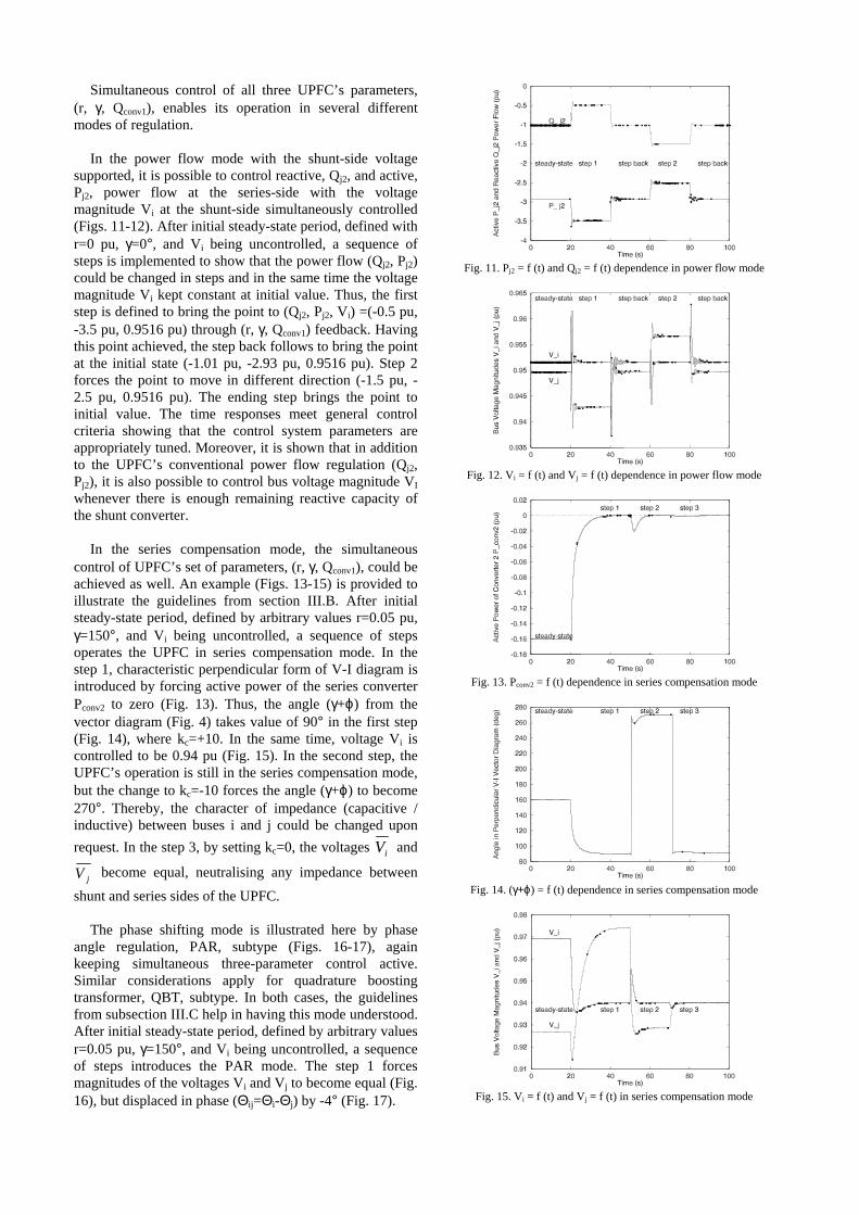
In the series compensation mode, the simultaneouscontrol of UPFC’s set of parameters, (r, γ, Qconv1), could beachieved as well. An example (Figs. 13-15) is provided toillustrate the guidelines from section III.B. After initialsteady-state period, defined by arbitrary values r=0.05 pu,γ=150°, and Vi being uncontrolled, a sequence of stepsoperates the UPFC in series compensation mode. In thestep 1, characteristic perpendicular form of V-I diagram isintroduced by forcing active power of the series converterPconv2 to zero (Fig. 13). Thus, the angle (γ+ϕ) from thevector diagram (Fig. 4) takes value of 90° in the first step(Fig. 14), where kc=+10. In the same time, voltage Vi iscontrolled to be 0.94 pu (Fig. 15). In the second step, theUPFC’s operation is still in the series compensation mode,but the change to kc=-10 forces the angle (γ+ϕ) to become270°. Thereby, the character of impedance (capacitive /inductive) between buses i and j could be changed uponrequest. In the step 3, by setting kc=0, the voltages iV and
jV become equal, neutralising any impedance betweenshunt and series sides of the UPFC.
The phase shifting mode is illustrated here by phaseangle regulation, PAR, subtype (Figs. 16-17), againkeeping simultaneous three-parameter control active.Similar considerations apply for quadrature boostingtransformer, QBT, subtype. In both cases, the guidelinesfrom subsection III.C help in having this mode understood.After initial steady-state period, defined by arbitrary valuesr=0.05 pu, γ=150°, and Vi being uncontrolled, a sequenceof steps introduces the PAR mode. The step 1 forcesmagnitudes of the voltages Vi and Vj to become equal (Fig.16), but displaced in phase (Θij=Θi-Θj) by -4° (Fig. 17).
Fig. 11. Pj2 = f (t) and Qj2 = f (t) dependence in power flow mode
Fig. 12. Vi = f (t) and Vj = f (t) dependence in power flow mode
Fig. 13. Pconv2 = f (t) dependence in series compensation mode
Fig. 14. (γ+ϕ) = f (t) dependence in series compensation mode
Fig. 15. Vi = f (t) and Vj = f (t) in series compensation mode

Fig. 16. Vi = f (t) and Vj = f (t) in phase angle regulation mode
Fig. 17. Θij = f (t) in phase angle regulation mode
In the same time, the voltage magnitude Vi is controlledto be 0.94 pu. In the second step, the PAR mode ispreserved, but with the phase displacement value of +4°.In the step 3, by setting ΘijREF to zero, and still keeping thevoltage magnitudes equalised (Vi additionally controlled to0.94 pu), the voltages iV and jV become equal.
V. CONCLUSIONS
Possible benefits of the UPFC’s injection model areinvestigated within power flow regulation problem. Theanalysis is carried out on a multi-machine test system andconcentrated on a transmission system compensationproblem. By using appropriate control system of the modelit is made possible to control simultaneously threetransmission system variables depending on the regulationmode (power flow, series compensation, and phaseshifting). By describing these fundamental characteristicsit is shown that the UPFC could be useful transmissionsystem controller, and furthermore represented by theinjection model with proposed control system.
VI. ACKNOWLEDGEMENTS
The authors wish to gratefully acknowledge thefinancial support provided by the Croatian Ministry ofScience and Technology and the Swedish Institute astimely impetus during this project.
VII. REFERENCES
[1] CIGRÉ TF 38.01.06, “Load flow control in high voltage powersystems using FACTS controllers,” January 1996
[2] CIGRÉ TF 38.01.07, “Analysis and control of power systemoscillations,” December 1996
[3] IEEE, “FACTS Application,” 96TP116-0, 1996
[4] N. Dizdarevic, S. Arnborg, and G. Andersson, “Possible alleviationof voltage stability problem by use of Unified Power FlowController,” Proceedings of the 32nd Universities Power EngineeringConference, Manchester, UK, September 1997, pp. 975-978
[5] N. Dizdarevic, S. Tesnjak, and G. Andersson, “On RegulatingCapabilities of Unified Power Flow Controller During VoltageEmergency Situations,” Proceedings of the 30th North AmericanPower Symposium, Cleveland, OH, USA, October 1998, pp. 275-282
[6] N. Dizdarevic, S. Tesnjak, G. Andersson, “Utilising ParametricSensitivity of Unified Power Flow Controller During VoltageUnstable Situations,” Proceedings of the IEEE PES Winter Meeting1999, New York, USA, February 1999, pp. 634-639
[7] P. Kundur, Power system stability and control, EPRI McGraw-Hill,ISBN 0-07-035958-X, 1994
[8] P.M. Anderson and A.A. Fouad, Power system control and stability,IEEE Press, ISBN 0-7803-1029-2, 1994
[9] M. Noroozian, L. Ängquist, M. Ghandhari, and G. Andersson, “Useof UPFC for optimal power flow control”, IEEE Trans. PowerDelivery, vol. 17, no. 4, October 1997, pp. 1629-1634
[10] M. Noroozian, L. Ängquist, Å. Petterson, M. Chamia, M.Ghandhari, and G. Andersson, “Improving power systems dynamicsby series-connected FACTS devices,” IEEE Trans. Power Delivery,vol. 12, no. 4, October 1997, pp. 1636-1642
VIII. BIOGRAPHIES
Nijaz Dizdarevic received his B.S. and M.S. degrees fromthe Faculty of Electrical Engineering and Computing,University of Zagreb, Croatia, in 1990 and 1994,respectively. In 1991 he joined the Department of ElectricPower Systems at the same Faculty. His researchexperience also included the Royal Institute of Technologyin Stockholm, Sweden, during 1996 and 1997. He iscurrently a Ph.D. student in the area of FACTSapplications in the systems prone to voltage instability.
Sejid Tesnjak received his B.S., M.S., and Ph.D. degreesfrom the Faculty of Electrical Engineering and Computing,University of Zagreb, Croatia, in 1972, 1977, and 1984,respectively. Since 1972 he has been with the Departmentof Electric Power Systems at the same Faculty wherecurrently is a Professor in the field of electric powersystem dynamics.
Göran Andersson (M’86, SM’91, F’97) received hisCiv.Ing. and Ph.D. degrees from Lund Institute ofTechnology, Sweden in 1975 and 1980, respectively. He isa Professor at the Department of Electric PowerEngineering, Royal Institute of Technology, Stockholm,Sweden. He is a Member of the Royal Swedish Academyof Engineering Sciences and the Royal Swedish Academyof Sciences.