power leaderâ„¢ ethernet gateway user's - ge digital energy
TRANSCRIPT

gPOWER LEADER™Ethernet Gateway
GEH–6505A
User’s Guide

GEH–6505
WARNINGS, CAUTIONS, AND NOTESAS USED IN THIS PUBLICATION
WARNINGS Warning notices are used in this publication to emphasize that hazardous voltages, cur-rents, or other conditions that could cause personal injury exist in this equipment ormay be associated with its use.
Warning notices are also used for situations in which inattention or lack of equipmentknowledge could cause either personal injury or damage to equipment.
CAUTIONS Caution notices are used for situations in which equipment might be damaged if careis not taken.
NOTES Notes call attention to information that is especially significant to understanding andoperating the equipment.
This document is based on information available at the time of its publication. Whileefforts have been made to ensure accuracy, the information contained herein does notcover all details or variations in hardware and software, nor does it provide for everypossible contingency in connection with installation, operation, and maintenance.Features may be described herein that are not present in all hardware and softwaresystems. GE Electrical Distribution & Control assumes no obligation of notice toholders of this document with respect to changes subsequently made.
GE Electrical Distribution & Control makes no representation or warranty, expressed,implied, or statutory, with respect to, and assumes no responsibility for the accuracy,completeness, sufficiency, or usefulness of the information contained herein. Nowarrantees of merchantability or fitness for purpose shall apply.
REFERENCES POWER LEADER™ is a registered trademark of GE Company.
Modbus RTU is a registered trademark of AEG Schneider Automation.
For details of the Modbus RTU protocol, refer to PI-MBUS-300 Rev. E fromModicon/AEG Schneider Automation.
For details of RS485 communications, refer to the EIA-485 standard.
©Copyright 1996 GE CompanyAll Rights Reserved

POWER LEADER™ Ethernet Gateway
Table of Contents
i
Chapter 1 – Introduction ...........................................................................................11–1 Overview .................................................................................................................................. 11–2 Physical Description ............................................................................................................... 21-3 Operational Description.......................................................................................................... 3
Message Format ................................................................................................................. 3Gateway/Host Interface.................................................................................................... 3
1–4 Specifications .......................................................................................................................... 41–5 Environmental Requirements................................................................................................ 41–6 Terminology............................................................................................................................ 4
Chapter 2 – Installation .............................................................................................52–1 Mounting................................................................................................................................. 52–2 Control Power Connections................................................................................................... 52–3 Ethernet Connection.............................................................................................................. 52–4 Modbus Connection ............................................................................................................... 62–5 Diagnostic Connection........................................................................................................... 62–6 Wiring Rules for Modbus Networks....................................................................................... 62–7 Modbus Equivalent Addresses ............................................................................................... 7
Chapter 3 – Configuration .........................................................................................83–1 Configuration Procedure ....................................................................................................... 83–2 Ethernet Gateway IP Address................................................................................................. 93–3 Baud Rate Specification ......................................................................................................... 93–4 Message Monitoring ............................................................................................................. 103–5 Ethernet Driver ..................................................................................................................... 103–6 Gateway Diagnostics ............................................................................................................. 11
Display Socket, IP Address and Subnet Mask................................................................ 11RS485 Loop-back Test ..................................................................................................... 11Ethernet Test ................................................................................................................... 11Exit Diagnostics Program ............................................................................................... 11Network Test – FACTORY USE ONLY .......................................................................... 12
3–7 Advanced Options – Technical Support Personnel ONLY ............................................... 12Updating the Gateway Software ..................................................................................... 12
Chapter 4 – Operation .............................................................................................13
Chapter 5 – Diagnostic Messages and Errors .......................................................145–1 Monitor Mode....................................................................................................................... 145–2 Processing Error Messages ................................................................................................... 14
Chapter 6 – Troubleshooting Guide .......................................................................15
RS485 Port Configuration Worksheets..................................................................16

POWER LEADER™ Ethernet Gateway
Table of Contents
ii
List of FiguresFigure 1. POWER LEADER Ethernet Gateway. ............................................................................................ 1Figure 2. Typical use of Ethernet Gateway. ................................................................................................... 2Figure 3. Front view of Ethernet Gateway, showing dimensions. ................................................................ 2Figure 4. Rear view of the Ethernet Gateway, showing Ethernet, RS485 and RS232 ports........................ 2Figure 5. Ethernet headers on Modbus messages. ........................................................................................ 3Figure 6. Mounting hole patter for Ethernet Gateway. ................................................................................ 5Figure 7. Connecting control power to the Ethernet Gateway..................................................................... 5Figure 8. Making the Ethernet connection to the Gateway. ........................................................................ 5Figure 9. Connecting an RS485 network to the Ethernet Gateway.............................................................. 6Figure 10. Termination of the RS485 network at the last Modbus device. ................................................. 6Figure 11. Connecting a dumb terminal to the RS232 port......................................................................... 6Figure 12. Terminal communications settings. ............................................................................................ 8Figure 13. Ethernet Gateway configuration menu........................................................................................ 8Figure 14. Gateway diagnostics menu.......................................................................................................... 11
List of Tables1. Examples of Modbus RTU compatible devices. ....................................................................................... 12. POWER LEADER Ethernet Gateway specifications. ................................................................................ 43. POWER LEADER Ethernet Gateway environmental requirements........................................................ 44. POWER LEADER commnet devices supported by the Modbus Concentrator...................................... 75. RS485 Port Settings.................................................................................................................................... 106. Diagnostic messages key............................................................................................................................ 147. Error message key. ..................................................................................................................................... 14

POWER LEADER™ Ethernet Gateway
Chapter 1 – Introduction
1
Chapter 1 – Introduction1–1 Overview
The GE POWER LEADER™ Ethernet Gateway(catalog number PLENETG01), shown in Figure 1,is a microprocessor-based device that connects oneto four RS485-based Modbus Remote Terminal Unit(RTU) networks to an industry-standard, high-speed Ethernet network. Up to 31 Modbus RTUdevices can be connected to each of the ModbusRTU networks.
Figure 1. POWER LEADER Ethernet Gateway.
The Ethernet Gateway works with GE’s PowerManagement Control System (PMCS), acomprehensive power management softwareplatform that acts as the ‘host’ to RS485 networksattached to the Ethernet Gateway. A special part ofthe PMCS called the Dynamic Data Exchange(DDE) server is a database that records theaddresses and configurations of all attacheddevices. The Ethernet Gateway serves as a pass-through device, interpreting the addressinginformation and routing queries from the host tothe Modbus RTU networks and passing answers tothose queries from the attached devices back to thehost.
The Ethernet Gateway strictly conforms to theModbus RTU protocol, providing the capability totie the supported Modbus RTU devices into anEthernet network. Table 1 contains a partial list ofdevices that are compatible with the EthernetGateway and conform to the Modbus RTUstandard.
Device DescriptionEPM 3710 Full-function, three-phase electronic
meter with optional pulse initiation,waveform capture, data logging, andprotective relay outputs.
EPM 3720 Full-function, three-phase electronicmeter with optional pulse initiation,waveform capture, data logging,protective relay outputs, and harmonicdistortion measurements.
Multilin 269 PlusMotor ManagementRelay
Protection for medium-voltageindustrial motors and associatedmechanical systems.
Multilin 565 FeederManagement Relay
Complete time-overcurrent phase andground protection by monitoring feederphase current and ground current.
Fanuc 90/30 PLC Programmable logic controller (PLC)for applications from simple relayreplacement to midrange processcontrol.
Fanuc 90/70 PLC Programmable logic controller withmultiple processors and programmingcapabilities for large, high-speedapplications.
ModbusConcentrator
Maps addresses of up to 32 attachedPOWER LEADER communicationsnetwork (commnet) devices toequivalent Modbus addresses for usewith the Ethernet Gateway.
Table 1. Examples of Modbus RTU compatible devices.
NOTE: PMCS is certified for use with powermanagement components manufactured 5/13/96or later. If your system interfaces to: 1) any tripunits, meters, or relays manufactured prior to5/13/96, or 2) any Spectra RMS™ Circuit Breakerswith MicroVersaTrip PM™ Trip Units, pleasecontact the POWER LEADER Customer SupportCenter at 1-800-843-3742.
As mentioned in Table 1, the Modbus Concentratorallows integration of POWER LEADER commnetdevices with Modbus RTU-compatible networks foruse with the Ethernet Gateway. See Section 3–5 formore details on the integration of commnet devicesinto Modbus networks.
Figure 2 illustrates a typical Modbus RTU networkconnected to a high-speed Ethernet through anEthernet Gateway.

POWER LEADER™ Ethernet Gateway
Chapter 1 – Introduction
2
EthernetGateway
HostPMCS
Ethernet
PL C90/30
Multi l in56 5
ModbusConcentrator
PL C90/70
Multi l in269+
E P M3710
E P M3720
OtherP C
OtherP C
POWE RLEADER
Meter
MVT - PMTrip Unit
Spect raE C M
PL E PM
RS485 Modbus RTURS485 Modbus RTU
commnet devi ces
Figure 2. Typical use of Ethernet Gateway.
1–2 Physical Description
Figure 3 is an outline drawing showing thedimensions of the Ethernet Gateway. Figure 4 is arear view of the Gateway showing its control power,Ethernet, RS485 and RS232 connections.
The following ports and connections are providedon the Gateway:
• A pair of Ethernet ports provides input and outputconnections to the either a 10BaseT or a 10Base2Ethernet network.
• Four RS485 ports support up to four Modbus RTUnetworks, labeled Network 1 to Network 4, with as
many as 31 Modbus devices each and up to 247Modbus addresses each. RS485 ports are DB-9 (9-pinD shell) connectors with the following pinassignments:
Data - Pin 1
Data + Pin 2
Ground Pin 5
• One RS232 port (also DB-9 style) allows connectionof a dumb terminal for configuration andtroubleshooting of the Ethernet Gateway.
• A standard PC-style power connector for AC controlpower input.
0.32 in.8.0 mm
Poweron/offswitch
Power HDD Reset
StatusLEDs
6.7 in.170.0 mm
7.32 in.196.0 mm
7.5 in.166.0 mm
Length:15.5 in.
393.0 mm
Figure 3. Front view with dimensions.
Control powerconnection
FourRS485ports
10Base2 and10BaseTEthernet ports
Com 1RS232 port fordumb terminal
1
2
3
4
Com 2RS232 portnot used
keyboard portnot used
Figure 4. Rear view showing ports.

POWER LEADER™ Ethernet Gateway
Chapter 1 – Introduction
3
1-3 Operational Description
The Ethernet Gateway transparently passes messagebetween the host and devices attached to theGateway. Figure 5 illustrates the stripping or addingof Ethernet headers to the Modbus messages. Thissection describes the nature of these messages andhow the Gateway routes them. The followinginformation is not necessary for configuration and use ofthe Ethernet Gateway, but is provided for users who may bedeveloping custom applications and need suchinformation.
Message Format
Messages sent from the software to RS485 devicesvia the Ethernet Gateway have a 15-byte headerinserted in front of the message. The header tellsthe Gateway where to send the message, how longthe message is, and if parity errors wereencountered. This header has the following format:
SS DD EE NN CCSS Sequence of ten AA hex bytes indicating the start
of a message
DD Destination device port number – the GatewayRS485 port to which the message should berouted (0 - 3)
EE Error status byte (0 = no parity errors, 1 = parityerrors encountered)
NN Number of bytes in the Modbus message
CC A one byte checksum calculated by adding thefirst 14 bytes in the header
The header is stripped off the message by theGateway and the remainder of the message is sentwithout changes to the destination device (orinterpreted by the Gateway if a configurationmessage).
Messages from the RS485 devices to the host areprocessed by adding the 15-byte header onto thestart of the message. For messages from devices tothe host, the byte in the DD position contains theRS485 port from which the message came.
Cyclic redundancy check (CRC) handling is doneby the host on the Ethernet and the RS485 deviceon the Modbus. The Gateway does not check theCRC when receiving messages from the host orfrom RS485 devices.
Ethernetheader
information
ModbusmessageHost
PMC S
Modbusmessage
Ethernetheader
information
Modbusmessage
Modbusmessage
Modbus messages from host to device - Ethernet Gateway str ips off header
Modbus messages f rom device to host - Ether net Gateway adds header
Message tr aveli ng on Ethernet Message tr avel ing on RS485
EthernetGateway
EthernetGateway
RS485device
RS485device
Figure 5. Ethernet headers on Modbus messages.
Gateway/Host Interface
The Gateway uses TCP/IP (Transmission ControlProtocol/Internet Protocol) to interface with thehost on the Ethernet.
The Gateway initially opens a socket and waits for ahost device to attempt to connect with the socket.
Once a connection is established, data messagesmay be transmitted to the Gateway (and ultimatelythe RS485 devices) and messages from RS485devices passed to the host.

POWER LEADER™ Ethernet Gateway
Chapter 1 – Introduction
4
1–4 Specifications
The specifications of the Ethernet Gateway arelisted in Table 2.
Parameter Value
Control power 90–132 Vac or 180–264 Vac,47–63 Hz; autorangingPower supply =150 VA min(contact your GE salesrepresentative for additionalvoltage options.)
Modbus communications Four RS485 ports, 1200 baud,2400 baud, 4800 baud, 9600baud and 19.2 Kbaud.
Ethernet communications One PCL-843 16-bit Ethernetcard; supports 10BaseT or10Base2 transport mediums.
StandardsUL ListedCSA Certified
508 & 840C22.2 No. 14
Table 2. POWER LEADER Ethernet Gateway specifications.
1–5 Environmental Requirements
The environmental requirements of the EthernetGateway are listed in Table 3.
Parameter Value
Operating temperature 0° C to +50° C
Storage temperature –20° C to +80° C
Relative humidity 10% to 95% noncondensing
Vibration response andendurance
IEC 255–21–1Severity Class 1
Fast transient surge ANSI C37.90.1
Radiated EMI withstand ANSI C37.90.2
Electrostatic discharge IEC 801–2Severity Class 4
Table 3. POWER LEADER Ethernet Gateway environmentalrequirements.
1–6 Terminology
Following are definitions of some of the terms usedin this document.
POWER LEADER – The GE family of comprehensivepower management devices and system software usedto minimize downtime and overall power cost.
PMCS – Power Management Control System software.
SCADA (supervisory control and data acquisition) – A groupof systems including power management and controlsystems.
DCS (distributed control system) – A group of systemsincluding building automation and statusmonitoring systems.
Ethernet – An open, industry-standard, high-perform-ance network communications protocol that operateson 10BaseT or 10Base2 transport mediums andyields communications rates up to 10 megabits persecond.
Modbus RTU (Remote Terminal Unit) – An open, industry-standard, high-performance network communica-tions protocol developed by Modicon/AEGSchneider Automation.
Modbus-compatible device – Any device equipped with aModbus RTU communications port.
Modbus master – A host computer running PMCSsoftware.
RS485/EIA485 – A physical standard for multi-drop,high-speed, noise-tolerant communications over atwisted pair network; often used with the ModbusRTU protocol.
Commnet – A GE proprietary communications networkstandard.
Commnet-compatible device – Any meter, relay, trip unit, orother device equipped with a commnet commu-nications port.
Commnet segment – A group of one to four commnet-compatible devices (including at most one waveform-capturing meter) with all communication ports wiredto a single Concentrator commnet port.

POWER LEADER™ Ethernet Gateway
Chapter 2 – Installation
5
Chapter 2 – Installation2–1 Mounting
The Ethernet Gateway may be mounted on ahorizontal surface or on a wall, preferably inside anenclosure or switchgear lineup. The Gateway shouldbe mounted so that it is spaced from enclosure wallsor from other components in the enclosure. Aminimum of two inches clearance should beallowed along the long sides of the Gateway, and atleast six inches clearance on the ends to allow forventilation and cable access. To wall mount theEthernet Gateway, attach the brackets to the chassisusing six of the provided screws through the sixholes on the inner edges of the mounting brackets.Then use the remaining four screws to secure thechassis to the wall through the holes in the outeredges of the brackets. Be sure that the chassis ismounted securely. The hole pattern for themounting flanges of the Ethernet Gateway is shownin Figure 6.
8 - R5 4 - R2.5
12 i n. 1 in.
7 -
1/8"
190.
6 m
m
305. 0 mm 23.0 mm
Figure 6. Mounting hole pattern for Ethernet Gateway.
2–2 Control Power Connections
Connect the control power cable included with theEthernet Gateway to the standard PC-style poweroutlet on the rear of the enclosure, as shown inFigure 7. See Section 1–4 for appropriate controlpower voltage ranges.
The ON switch for the Ethernet Gateway is locatedon the front panel. Make sure the Gateway ismounted in a location where the power switch isnot likely to be accidentally hit or switched off.
Figure 7. Connecting control power to the Ethernet Gateway.
2–3 Ethernet Connection
10BaseT and 10Base2 connections are provided onthe back of the Ethernet Gateway to connect theGateway to the Ethernet network, as shown inFigure 8. The Gateway is equipped with a PCL-84316-bit Ethernet card.
Figure 8. Making the Ethernet connection to the Gateway.
POWER LEADER™ Ethernet Gateway
Chapter 2 – Installation
6
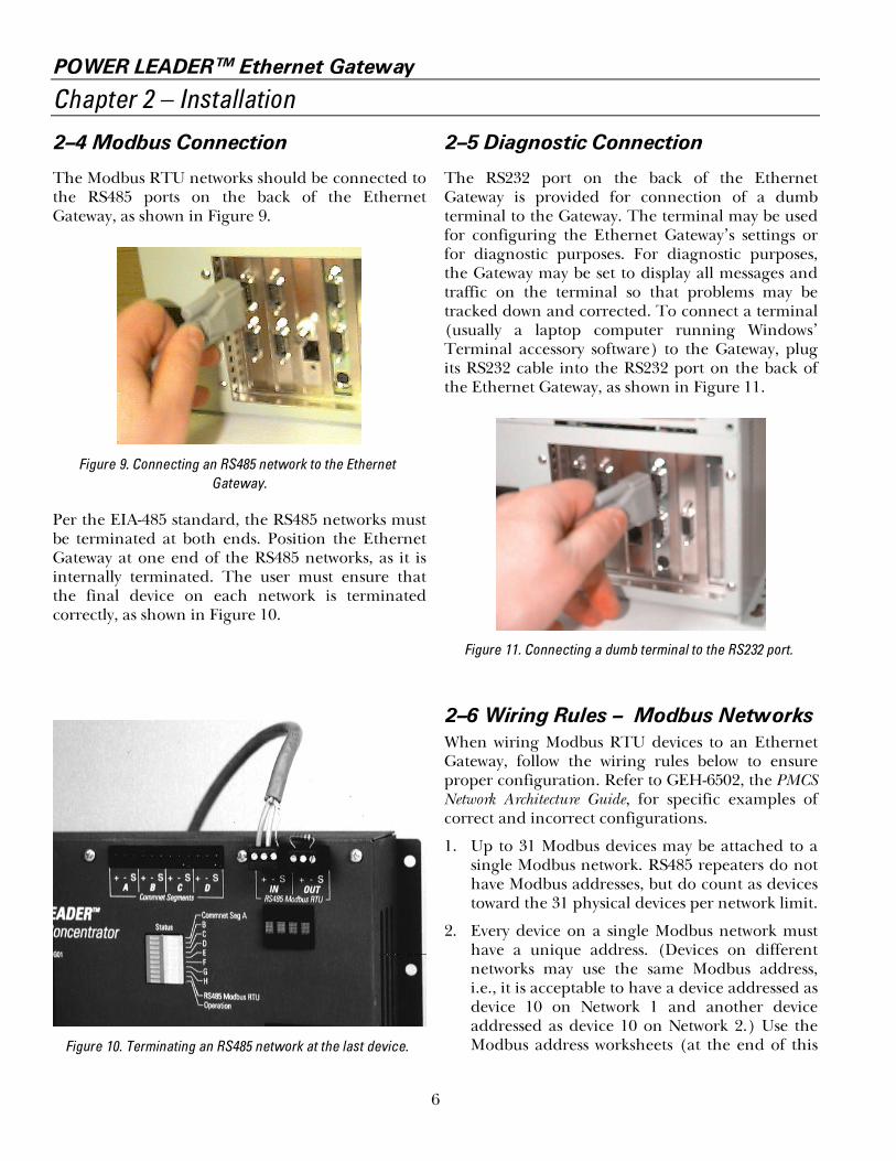
2–4 Modbus Connection
The Modbus RTU networks should be connected tothe RS485 ports on the back of the EthernetGateway, as shown in Figure 9.
Figure 9. Connecting an RS485 network to the EthernetGateway.
Per the EIA-485 standard, the RS485 networks mustbe terminated at both ends. Position the EthernetGateway at one end of the RS485 networks, as it isinternally terminated. The user must ensure thatthe final device on each network is terminatedcorrectly, as shown in Figure 10.
Figure 10. Terminating an RS485 network at the last device.
2–5 Diagnostic Connection
The RS232 port on the back of the EthernetGateway is provided for connection of a dumbterminal to the Gateway. The terminal may be usedfor configuring the Ethernet Gateway’s settings orfor diagnostic purposes. For diagnostic purposes,the Gateway may be set to display all messages andtraffic on the terminal so that problems may betracked down and corrected. To connect a terminal(usually a laptop computer running Windows’Terminal accessory software) to the Gateway, plugits RS232 cable into the RS232 port on the back ofthe Ethernet Gateway, as shown in Figure 11.
Figure 11. Connecting a dumb terminal to the RS232 port.
2–6 Wiring Rules – Modbus NetworksWhen wiring Modbus RTU devices to an EthernetGateway, follow the wiring rules below to ensureproper configuration. Refer to GEH-6502, the PMCSNetwork Architecture Guide, for specific examples ofcorrect and incorrect configurations.
1. Up to 31 Modbus devices may be attached to asingle Modbus network. RS485 repeaters do nothave Modbus addresses, but do count as devicestoward the 31 physical devices per network limit.
2. Every device on a single Modbus network musthave a unique address. (Devices on differentnetworks may use the same Modbus address,i.e., it is acceptable to have a device addressed asdevice 10 on Network 1 and another deviceaddressed as device 10 on Network 2.) Use theModbus address worksheets (at the end of this

POWER LEADER™ Ethernet Gateway
Chapter 2 – Installation
7
manual) to record the devices attached to eachnetwork and verify that each device on eachnetwork has a unique address.
3. Modbus Concentrators may be used to addPOWER LEADER commnet devices to aModbus network. The Concentrator assigns aModbus-equivalent address to each commnetdevice attached to it. See Section 2-7 for adiscussion of commnet and Modbus-equivalentaddresses.
NOTE: While Modbus Concentrators are countedas regular Modbus devices, the commnet devicesattached to Modbus Concentrators do NOT counttoward the 31 device/network limit, but AREconsidered in the 247 address/network limit.
4. No connections between Modbus networks arepermitted, either directly or through repeaters.
5. Modbus networks are constrained to amaximum 4,000 feet of communication cablewithout repeaters.
6. RS485 repeaters may be used to extend thewiring length of a Modbus network or toprovide isolation between runs of cable in aModbus network. Refer to GEH-6502 forappropriate wiring lengths with repeaters.
2–7 Modbus Equivalent Addresses
A maximum of 31 Modbus devices can besupported on a single RS485 network of theEthernet Gateway. However, the Modbus RTUprotocol permits up to 247 individual addresses tobe recognized. These additional 216 addresses maybe utilized by commnet devices attached to a specialModbus device, the Modbus Concentrator.
Commnet is a communications protocol utilized bymany of the devices from GE’s POWER LEADERfamily of power management devices. The ModbusConcentrator is a Modbus RTU device that permitscommnet devices to be assigned Modbus-equivalentaddresses. Each Modbus Concentrator keeps trackof up to 32 commnet devices and directs trafficbetween the Modbus network and the commnet
devices. To the Modbus network, the commnetdevices appear as valid Modbus addresses.
To provide seamless integration of commnet-compatible devices into the Modbus RTU network,the Concentrator directly maps commnet addressesto equivalent Modbus addresses. The valid range ofcommnet addresses recognized by the concentratoris 300–514. These addresses are one-to-one mappedto the equivalent Modbus address range of 33–247.
For a more detailed discussion of commnet devicesand the function of the Modbus Concentrator, seeGEH-6491, the Modbus Concentrator Users Guide.
Table 4 lists commnet devices supported by theModbus Concentrator (and the Ethernet Gateway).
Device Description
POWER LEADER EPM Full-function, three-phase electronicmeter with optional pulse initiation;simple retrofit to existingelectromechanical installations. SeeGEH–6302 for a full description.
POWER LEADER Meter Full-function three-phase meter withoptional protective relaying andwaveform capture. See GEH–5892.
POWER LEADER MDPOvercurrent Relay
Three-phase and ground protectionagainst overloads and rapiddetection of short circuits.See GEK–100682.
Spectra ECM™ Advanced motor protection in full-voltage-nonreversing (FVNR) andfull-voltage-reversing (FVR)combination starter applications.See GEH–6435.
MicroVersaTrip PM™ tripunit in Spectra RMS™molded-case circuitbreakers
Overcurrent protection and optionalfull-function metering and protectiverelaying. See GEH–5934.
MicroVersaTrip PM™ tripunit in AKR, PowerBreak® and PowerBreak® II insulated-casecircuit breakers.
Overcurrent protection and optionalfull-function metering and protectiverelaying. See GEH–6273.
Table 4. POWER LEADER commnet devices supported by theModbus Concentrator.

POWER LEADER™ Ethernet Gateway
Chapter 3 – Configuration
8
Chapter 3 – Configuration
The Ethernet Gateway needs to be properlyconfigured to communicate with your RS485networks. Two items are critical to properperformance of your Gateway: the Gateway’sEthernet address and the RS485 portcommunication settings. The Gateway’s Ethernetaddress should be set so that the host software willknow how to address messages to the Gateway. Youmust configure the Ethernet Gateway with theappropriate baud rate and communications settingsfor each RS485 port to match attached RS485network. After initial setup, you should only need tomake changes to the Gateway’s settings after addingdevices or making system changes.
Follow the instructions in Section 3-1 to perform theinitial configuration. After the network isoperational, you may make configuration changesthrough the dumb terminal. These procedures aredescribed in the following sections.
In all cases, be sure to save any configurationchanges to the Gateway’s hard drive (option 12) forsafe retrieval in the event of a power loss.
3–1 Configuration Procedure
Configuration of the Gateway requires a dumbterminal with RS232 port set to 19.2 Kbps, 8 databits, no parity, and 1 stop bit. The easiest way to dothis is to use a portable computer with an RS232port, and run the Terminal accessory program fromWindows.
Use a null modem cable to attach the laptop to theRS232 port of the Gateway, power up the laptopand launch the Terminal program (located in theAccessories program group in the Windowsprogram manager). Click on the Settings menu,then choose Communications. Set yourcommunications options to look like figure 12.
When you have set your communications options,close the options window and power up the Gateway(the ON switch is located on the front panel).
When the Gateway finishes powering up, thefollowing message is transmitted to the terminal:
Figure 12. Terminal communications settings.
You are now ready to configure the Gateway, asoutlined below:
1. Type SET (must be typed in capital letters)then press <ENTER> to bring up theconfiguration menu. If you make an errortyping in this string, wait ten seconds and tryagain.
2. The terminal displays the configurationmenu:
Figure 13. Ethernet Gateway configuration menu.

POWER LEADER™ Ethernet Gateway
Chapter 3 – Configuration
9
Enter the setting number you want to change,then press <ENTER>.
NOTE: The lower portion of the Configuration Menu islabeled Advanced Options. These options are for useONLY by GE technical support personnel. Do NOT selectany of these options. IF YOU ACCIDENTALLY SELECTANY ADVANCED OPTION FROM THECONFIGURATION MENU, PRESS <ESC> TO EXIT,THEN PRESS <ENTER> TO RETURN TO THECONFIGURATION MENU.
3. At the prompt, enter the new setting, thenpress <ENTER>. If you enter an invalid value,the following message will be displayed:
Pressing <ENTER> returns you to theconfiguration menu.
NOTE: Pressing <ESC> while entering a new value for asetting discards the changes and redisplays theconfiguration menu.
4. Configure parameters as desired, by repeatingsteps 2 and 3.
5. When you are finished making changes, selectoption 12, .The configuration file on drive A is modifiedwith the new parameters and the terminaldisplays the following message:
If an error has been made, select option 13, The
currently displayed settings are discarded andthe following message is displayed on theterminal:
Correct the error by repeating steps 1–3.
6. When you have saved the configuration andexited, the Ethernet Gateway is ready foroperation. Turn off the unit until the rest ofthe network is ready for operation.
3–2 Ethernet Gateway IP Address
Ethernet Gateway’s IP address must be properly setfor it to receive messages sent by the host software.Consult your LAN personnel or systemadministrator for assistance in selecting the correctIP address. Follow Section 3–7 to modify the IPaddress.
WARNING: Setting the Ethernet Gateway to an incorrector conflicting IP address can cause SERIOUS networkproblems. ALWAYS consult your LAN personnel or systemadministrator before making any changes to the IPaddress.
3–3 Baud Rate Specification
You must configure the baud rate andcommunications settings on each RS485 port tomatch the baud rate on the attached RS485network. The Gateway supports RS485 speeds of1200 baud, 2400 baud, 4800 baud, 9600 baud and19.2 Kbaud. Default settings are 19.2 Kbaud, 8 databits, no parity, 1 stop bit.
Each network’s baud rate depends on the devicesattached to it – see GEH-6502, the PMCS NetworkArchitecture Guide, for more details on this.
To configure the baud rate and communicationssettings for any of the four RS485 ports, followSection 3-1, referencing the special instructionsgiven below regarding the communications options.
Table 5 lists the valid entries for options 1 through8 of the Configuration menu, relating to the baudrate and communications settings of RS485 ports.

POWER LEADER™ Ethernet Gateway
Chapter 3 – Configuration
10
Option Number: Valid Entries at Prompt:
1 = RS485 Port 13 = RS485 Port 25 = RS485 Port 37 = RS485 Port 4
0 = 1200 baud 4 = 19200 baud1 = 2400 baud 5 = 38400 baud2 = 4800 baud 6 = 57600 baud3 = 9600 baud
2 = RS485 Port 14 = RS485 Port 26 = RS485 Port 38 = RS485 Port 4
Data Bits: 0 = 7 data bits1 = 8 data bits
Stop Bits: 0 = 1 stop bit1 = 2 stop bits
Parity: 0 = None1 = Even2 = Odd
Table 5. RS485 Port Settings .
1. Follow the procedure outlined in Section 3-1to configure the Gateway.
2. At the Configuration menu, select the optionnumber, then press <ENTER>. At the prompt,enter the new setting, then press <ENTER>. Foroptions 1, 3, 5, and 7, enter the new settingfrom the options in Table 5, then press<ENTER>. For options 2, 4, 6, and 8, enter eachnew parameter as prompted, using the correctentries from Table 5. If you enter an invalidvalue, the following message display:
Press <ENTER> to return to the Configurationmenu.
NOTE: Pressing <ESC> while entering a new value for asetting discards the changes and redisplays theConfiguration menu.
3. Follow steps 5 and 6 of Section 3-1 to save anychanges and exit configuration mode.
3–4 Message Monitoring
For diagnostic purposes, you may want to monitormessage traffic across the RS485 ports. This can bedone on a terminal connected to the RS232 port.You may monitor messages on any single RS485port or on all four ports simultaneously.
Selecting menu item 14 allows you to select whetheror not messages are sent to the RS232 port inmonitor mode and which RS485 ports are to bemonitored. The following prompt appears:
Enter your selection from the above choices.
3–5 Ethernet Driver
Menu item 10 permits the Ethernet driver to beselected. Most systems utilize DIX Ethernet; ahandful use IEEE Ethernet. The Gateway defaultsto the DIX Ethernet driver. If your network does notfunction under DIX Ethernet and you haveeliminated all other potential sources of trouble,change the driver setting to IEEE Ethernet and retrycommunications. If this does not resolve theproblem, contact Customer Service.

POWER LEADER™ Ethernet Gateway
Chapter 3 – Configuration
11
3–6 Gateway Diagnostics
Selecting menu item 11 exits the Gateway softwareand runs the Gateway diagnostics program. TheGateway Diagnostics menu shown in Figure 14 isdisplayed on the terminal.
Figure 14. Gateway Diagnostics menu.
Display Socket, IP Address and SubnetMask
Select menu item 1 to display the IP address andsubnet mask for the Gateway.
RS485 Loop-back Test
Select menu item 2 to perform a loop-back test onan RS485 port. The loop-back test is useful foridentifying the RS485 ports and for testingcommunications on an RS485 port. To completethis test, you will need a short RS485 cable, availableat an electronics retailer.
The RS485 port being tested is connected toanother RS485 port and a test message istransmitted from the port being tested. Thefollowing prompt appears:
Enter the port to be tested: 1, 2, 3, or 4. Thefollowing message displays:
(where X is the port being tested).
If the loop-back is successful, the following messagewill be displayed:
(where Y is the loop-back port).
If the loop-back is unsuccessful, the followingmessage displays:
Default settings on the RS485 ports for the loop-back tests are 115.2 Kbps, 8-N-1.
Ethernet Test
Select menu item 3 to test the Gateway’s internalEthernet connections. This performs a self-test ofthe Gateway’s Ethernet card to ensure that it isfunctioning correctly. The following messagedisplays:
If the test passes, the following message displays:
If the test fails, the following message displays:
In either case, pressing <ENTER> returns you to thediagnostics menu.
Exit Diagnostics Program
Select menu item 4 to exit the Gateway diagnosticsoftware and reload the Gateway software.

POWER LEADER™ Ethernet Gateway
Chapter 3 – Configuration
12
Network Test – FACTORY USE ONLY
NOTE: A client program may be requested from GE torun on the host when performing the network test. Theclient attempts to establish a connection to a server (theGateway) with the specified IP address, subnet mask andport number.
Menu item 5 is for factory testing of the network.End users should NOT select this option. This testattempts to communicate with a host across theEthernet. To complete this test, you will need anRS232 null modem cable, available at an electronicsretailer. Before performing this test, the host PCmust be running the client software mentionedabove, and must be connected to the EthernetGateway via the null modem cable.
When you select menu item 4, the followingmessage is displayed:
If the network test passes, the following message isdisplayed:
If the network test fails, the following message isdisplayed:
In either case, pressing <ENTER> returns you to thediagnostics menu.
3–7 Advanced Options – TechnicalSupport Personnel ONLY
Ordinarily these options will have been configuredby the system integrator or direct from the factory;you should NOT alter any of the settings from theadvanced options area of the Configuration menu.
WARNING: ALTERING ANY OF THESE SETTINGSMAY RENDER THE ETHERNET GATEWAYINOPERABLE. IF YOU ACCIDENTALLY SELECT ANYOPTION FROM THE ADVANCED SETTINGS, PRESS<ESC> TO EXIT, THEN PRESS <ENTER> TO RETURNTO THE CONFIGURATION MENU.
Select menu item 15 to modify the Gateway socketidentifier. The format is: ####.
Select menu item 16 to modify the Gateway InternetProtocol (IP) address. Enter the IP address in dotnotation, e.g., 123.145.51.126.
Select menu item 17 to modify the Gateway subnetmask. Enter the subnetwork mask in dot notation,e.g., 255.255.255.0.
Select menu item 18 to modify the FTP PC/TCPkernal serial number. The number has thefollowing format: 1234-5678-9012.
Select menu item 19 to modify the FTP PC/TCPkernal authentication key. The number has the fol-lowing format: 1234-5678-9012.
Select menu item 21 to modify the Gateway Router.This item has the following format: 0.0.0.0, 0.0.0.0,0.0.0.0 Note that the Router numbers may havemultiple digits in each placeholder, and each set offour numbers represents one router; for example,205.109.43.11, 0.0.0.0, 0.0.0.0 is configured for onerouter. The Gateway may be configured with amaximum of three routers.
Updating the Gateway Software
Option 20 of the Configuration menu allows updat-ing of the Ethernet Gateway’s operating softwareand is for use ONLY by factory service personnel.

POWER LEADER™ Ethernet Gateway
Chapter 4 – Operation
13
Chapter 4 – Operation
The Ethernet Gateway, once properly configured,requires no user intervention for operation.
During normal operation, the Ethernet Gatewaypasses messages to and from the attached Modbusdevices and translates these messages between theEthernet and Modbus RTU protocols.
Should power to the Ethernet Gateway be inter-rupted, communications between the host and theRS485 networks will resume automatically andimmediately when power is restored.
Likewise, if the Ethernet connection or any of theRS485 connections are broken, communicationswill be immediately resumed when the connectionsare restored.
Any errors encountered by the Ethernet Gatewaywill result in a message being sent back to the host,where it will be interpreted and displayed for correc-tive action by the operator.
All processing error messages are sent to the RS232port. Processing error messages are listed in Section5-1 of this manual.

POWER LEADER™ Ethernet Gateway
Chapter 5 – Errors and Diagnostic Messages
14
Chapter 5 – Diagnostic Messages and Errors
5–1 Monitor Mode
The Ethernet Gateway can be set to send diagnosticmessages to the RS232 port to be displayed on aterminal (see Chapter 3). These diagnosticmessages can be very useful in tracking down errorsin configuration or device addressing.
Diagnostic messages sent to the RS232 port in moni-tor mode have the following format:
Table 6 explains what each field means:
Field Meaning
The relative time of the message in timerticks. This rolls over every1,000,000,000 timer ticks.
Indicates the direction of the message:E-n (n = 1,2,3 or 4) indicates a message
sent from the Ethernet Gateway toRS485 port number 1,2,3 or 4
n-E indicates a message sent fromRS485 port number 1,2,3 or 4 to theEthernet Gateway
Header byte added to regular Modbusmessage. Printed as two hex digits.
Binary data of regular Modbus message.Printed as two hex digits.
Table 6. Diagnostic messages key.
5–2 Processing Error Messages
Table 7 gives error messages that may be generatedby the Gateway and displayed at the PMCS host.
Message Meaning
Error - Buffer Overflow One or more buffers haveoverflowed.
Error - Writing to FlashROM
An attempt to write to flash ROM(drive A) has failed.
Error - Reading FlashROM
An attempt to read the flash ROM(drive A) has failed.
Table 7. Error message key.
POWER LEADER™ Ethernet Gateway
Chapter 6 – Troubleshooting Guide
15
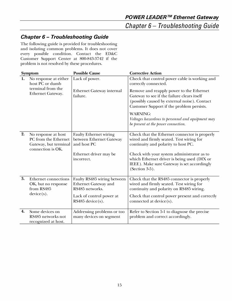
Chapter 6 – Troubleshooting GuideThe following guide is provided for troubleshootingand isolating common problems. It does not coverevery possible condition. Contact the ED&CCustomer Support Center at 800-843-3742 if theproblem is not resolved by these procedures.
Symptom Possible Cause Corrective Action1. No response at either
host PC or dumbterminal from theEthernet Gateway.
Lack of power.
Ethernet Gateway internalfailure.
Check that control power cable is working andcorrectly connected.
Remove and reapply power to the EthernetGateway to see if the failure clears itself(possibly caused by external noise). ContactCustomer Support if the problem persists.
WARNING:Voltages hazardous to personnel and equipment maybe present at the power connection.
2. No response at hostPC from the EthernetGateway, but terminalconnection is OK.
Faulty Ethernet wiringbetween Ethernet Gatewayand host PC
Ethernet driver may beincorrect.
Check that the Ethernet connector is properlywired and firmly seated. Test wiring forcontinuity and polarity to host PC.
Check with your system administrator as towhich Ethernet driver is being used (DIX orIEEE). Make sure Gateway is set accordingly(Section 3-5).
3. Ethernet connectionsOK, but no responsefrom RS485device(s).
Faulty RS485 wiring betweenEthernet Gateway andRS485 networks.
Lack of control power atRS485 device(s).
Check that the RS485 connector is properlywired and firmly seated. Test wiring forcontinuity and polarity on RS485 wiring.
Check that control power present and correctlyconnected at device(s).
4. Some devices onRS485 networks notrecognized at host.
Addressing problems or toomany devices on segment
Refer to Section 5-1 to diagnose the preciseproblem and correct accordingly.

POWER LEADER™ Ethernet Gateway
Configuration Worksheets
16
RS485 Port Configuration WorksheetsUse the following worksheets to record the devicesattached to the Ethernet Gateway for reference andtroubleshooting. Record the Ethernet Gateway’sEthernet address on the first page only, then fill inthe information on the Modbus devices attached to
each network: device type and physical location,and the Modbus address assigned to it.
Ethernet Gateway Address:
RS485 Port 1 Worksheet
Baud Rate for RS485 Port 1
ModbusNetwork
DeviceNumber Device Type & Physical Location / Notes
ModbusAddress
1 11 21 31 41 51 61 71 81 91 101 111 121 131 141 151 161 171 181 191 201 211 221 231 241 251 261 271 281 291 301 31

POWER LEADER™ Ethernet Gateway
Configuration Worksheets
17
RS485 Port 2 Worksheet
Baud Rate for RS485 Port 2
ModbusNetwork
DeviceNumber Device Type & Physical Location / Notes
ModbusAddress
2 12 22 32 42 52 62 72 82 92 102 112 122 132 142 152 162 172 182 192 202 212 222 232 242 252 262 272 282 292 302 31

POWER LEADER™ Ethernet Gateway
Configuration Worksheets
18
RS485 Port 3 Worksheet
Baud Rate for RS485 Port 3
ModbusNetwork
DeviceNumber Device Type & Physical Location / Notes
ModbusAddress
3 13 23 33 43 53 63 73 83 93 103 113 123 133 143 153 163 173 183 193 203 213 223 233 243 253 263 273 283 293 303 31

POWER LEADER™ Ethernet Gateway
Configuration Worksheets
19
RS485 Port 4 Worksheet
Baud Rate for RS485 Port 4
ModbusNetwork
DeviceNumber Device Type & Physical Location / Notes
ModbusAddress
4 14 24 34 44 54 64 74 84 94 104 114 124 134 144 154 164 174 184 194 204 214 224 234 244 254 264 274 284 294 304 31

gGE Electrical Distribution & Control
General Electric Company41 Woodford Ave., Plainville, CT 06062
GEH-6505A 0996 © 1996 General Electric Company