power logic sensors safety connectivity
TRANSCRIPT
Essential ComponentsGet the right components, at the right price, right where you need them.
Power
Logic
Operator
Interface
ConnectivitySafetySensors

100-C.....................................1-29100-CR ..................................1-49100-D.....................................1-36100-G.....................................1-41100-K .....................................1-27100S-C ..................................1-30100S-D ..................................1-37103T/107T.............................1-45140A.........................................1-5140-CMN.................................1-8140F .......................................2-52140M-C/-D/-F.........................1-8140M-I/-J/-L ...........................1-9140M-H/-J/-L/-N .................1-11140M-RC ..............................1-48140UE ....................................1-17141A.......................................1-511485 .......................................4-141489 .......................................2-491492 .......................................4-111492-FB ................................2-511492-J......................................4-31492-L .....................................4-61492-PDE..............................4-101492-RCD .............................2-411492-SP ................................2-43150-C.....................................1-76150-F .....................................1-78156-B .....................................1-431606-XL.................................2-591609-U/-P/-S........................2-621732 .......................................4-331752 .......................................5-271760 .......................................2-271761 .......................................2-291762 .......................................2-311763 .......................................2-301764 .......................................2-341766 .......................................2-331769 .......................................2-261783 .......................................4-291790D ....................................4-31190E/191E ............................1-45190S/191S ............................1-46193-EC ..................................1-68193-ED/-EE...........................1-64193-K .....................................1-61193-T1 ...................................1-62
Bulletin Number Page Bulletin Number Page Bulletin Number Page194E ....................................1-105194E-Y ................................1-107194L .......................................1-9920A.........................................1-9220B.........................................1-9422A.........................................1-8222B.........................................1-8622C ........................................1-9022D.........................................1-8822F .........................................1-842706-P...................................3-452711C ....................................3-44280 .........................................4-12280A/281A ............................1-74280D/281D............................1-74283A/283D............................1-74284A/284D............................1-7442BT ......................................6-1342CA ......................................6-1042CM .....................................6-1242EF .........................................6-742G ........................................6-1442JS .........................................6-944B.........................................6-1345BPD ...................................6-1545CLR....................................6-1645CPD ...................................6-1645PVA ....................................6-1745AST ....................................6-1748MS...................................6-17A440E .........................................5-9440F .......................................5-20440G ........................................5-7440J .......................................5-10440K.........................................5-6440L .......................................5-14440N-S ....................................5-5440N-Z ....................................5-3440P.......................................5-11440R ......................................5-22442L .......................................5-20445L .......................................5-164983-D...................................2-5454RF ......................................6-4055RF ......................................6-4156RF ......................................6-4257RF ......................................6-43700-CF/-CRF........................2-18
700-FE ...................................2-13700-FS...................................2-14700-HA ....................................2-6700-HC ....................................2-8700-HK ....................................2-9700-HL ..................................2-10700-HP ..................................2-12700-K .....................................2-17700-SH ..................................2-21800F .........................................3-7800FC ....................................3-28800FD ....................................3-11800FP ....................................3-18809S.......................................1-73813S.......................................1-73814S.......................................1-73817S.......................................1-73825-P .....................................1-71836E.......................................6-34837E.......................................6-36839E.......................................6-38855B ......................................3-38855BL ....................................3-39855BM ...................................3-39855BS ....................................3-39855E/-D ...................................3-4855F .......................................3-36855H ......................................3-37855P.......................................3-30855PB ....................................3-30855PC....................................3-30855PD....................................3-31855PS ....................................3-31855T .......................................3-32855W .....................................3-40855X ....................................3-38A871A.......................................4-42871TM ...................................6-25871P.......................................6-26872C ......................................6-23873P.......................................6-32875C ......................................6-30889D ......................................4-36889N ......................................4-39889P.......................................4-40889R ......................................4-38898D/898P............................4-41900-TC ..................................2-22
Bulletin Index

Motor Protection Circuit Breakers . . . . . . . . . . . . . . . . .1-2Motor Circuit Protectors . . . . . . . . . . . . . . . . . . . . . . . . . .1-4Molded Case Circuit Breakers . . . . . . . . . . . . . . . . . . . .1-17Contactors . . . . . . . . . . . . . . . . . . . . . . . . . . . . . . . . . . . . . . .1-24Solid State Contactors . . . . . . . . . . . . . . . . . . . . . . . . . . .1-43Starters . . . . . . . . . . . . . . . . . . . . . . . . . . . . . . . . . . . . . . . . . .1-45Starter Components . . . . . . . . . . . . . . . . . . . . . . . . . . . . .1-47Mounting System . . . . . . . . . . . . . . . . . . . . . . . . . . . . . . .1-50Motor Protection . . . . . . . . . . . . . . . . . . . . . . . . . . . . . . . .1-58ArmorStart™/Distributed Motor Controllers . . . . .1-74Soft Starters . . . . . . . . . . . . . . . . . . . . . . . . . . . . . . . . . . . . .1-75Drives . . . . . . . . . . . . . . . . . . . . . . . . . . . . . . . . . . . . . . . . . . . .1-80Control and Load Switches . . . . . . . . . . . . . . . . . . . . . .1-98
Relays and Timers . . . . . . . . . . . . . . . . . . . . . . . . . . . . . . . . .2-2Solid State Devices . . . . . . . . . . . . . . . . . . . . . . . . . . . . . .2-20Temperature Controllers . . . . . . . . . . . . . . . . . . . . . . . . .2-22Programmable Controllers . . . . . . . . . . . . . . . . . . . . . .2-23Circuit Protection . . . . . . . . . . . . . . . . . . . . . . . . . . . . . . . .2-38Surge and Filter Protection . . . . . . . . . . . . . . . . . . . . . .2-53Power Supplies . . . . . . . . . . . . . . . . . . . . . . . . . . . . . . . . . .2-57
Control and Indicating Units . . . . . . . . . . . . . . . . . . . . . .3-2Graphic Terminals and Message Displays . . . . . . .3-42
Terminal Blocks . . . . . . . . . . . . . . . . . . . . . . . . . . . . . . . . . . .4-2Wiring Systems . . . . . . . . . . . . . . . . . . . . . . . . . . . . . . . . . .4-11ArmorConnect™ Power Media . . . . . . . . . . . . . . . . . .4-12DeviceNetTM Media . . . . . . . . . . . . . . . . . . . . . . . . . . . . .4-14Ethernet Media . . . . . . . . . . . . . . . . . . . . . . . . . . . . . . . . . .4-26Distributed I/O . . . . . . . . . . . . . . . . . . . . . . . . . . . . . . . . . .4-30Connection Systems . . . . . . . . . . . . . . . . . . . . . . . . . . . .4-35
Safety Interlock and Guard Locking Switches . . . .5-2E-stops and Trip Devices . . . . . . . . . . . . . . . . . . . . . . . . . .5-8Presence Sensing . . . . . . . . . . . . . . . . . . . . . . . . . . . . . . . .5-12Safety Relays and Controllers . . . . . . . . . . . . . . . . . . . .5-21Safety Enabled Actuators . . . . . . . . . . . . . . . . . . . . . . . .5-28
Phototelectric Sensors . . . . . . . . . . . . . . . . . . . . . . . . . . . .6-2Inductive Proximity Sensors . . . . . . . . . . . . . . . . . . . . .6-22Capacitive Proximity Sensors . . . . . . . . . . . . . . . . . . . .6-29Ultrasonic Sensors . . . . . . . . . . . . . . . . . . . . . . . . . . . . . . .6-31Condition Sensing Switches . . . . . . . . . . . . . . . . . . . . .6-33Industrial RFID Products . . . . . . . . . . . . . . . . . . . . . . . . .6-40
Table of Contents
LOGIC 2-1
OPERATOR INTERFACE 3-1
CONNECTIVITY 4-1
SAFETY 5-1
SENSORS 6-1
POWER 1-1

Essential Components
Catalogue numbers in bold aretypically the highest availableproducts.
Within these pages, you will find an extensive selection
of your essential Allen-Bradley® component products.
Look through this catalogue, call your local Rockwell
Automation representative, or visit us online.
There are many options to help you choose the products
that are fundamental to your success and give you the
greatest value.
With Allen-Bradley components, you will find the
highest quality at a fair price, an intuitive product
selection, quick turnaround time, and fast delivery.
Furthermore, you will get components that perform
to your specifications, with the services and support
you demand. Rockwell Automation offers quality
Allen-Bradley industrial components that have been
used by customers like you for more than 100 years.
This catalogue only highlights our most essential
components; for a complete product selection,
visit our online catalogue at www.ab.com/catalogs.
Get the right components, at the right price, right where you need them.

Broad Selection of Quality Products
• Optimise machine performance with the right product
• Compliant with international standards
• Extensive selection for single-source convenience
and supply chain efficiencies
• Quality components designed for your
critical applications
Flexible, Hassle-Free Ordering
• Call your local Rockwell Automation representative
• Product Selection Toolbox allows you to select and configure the products
you need with confidence
• Visit www.rockwellautomation.com/distributor to find your local Allen-Bradley® Distributor(s)
Advanced Services & Support
• Responsive, knowledgeable network of local distributors and product representatives, available
globally in more than 80 countries
• Local technical specialists to make installation and integration easy
• Post-sale support to keep operation and maintenance optimal
Save Time & Reduce Costs
• Increase quality, productivity, and flexibility while reducing costs
• Competitive prices and local service and support keep your project within budget and on schedule

Services & SupportEssential Components, Essential ServicesOptimise the performance and utilisation of your automation
assets to meet your production and business goals.
Assessment Services
A service assessment will identify the personnel and equipment issues that
hinder your production performance and help you develop a maintenance
strategy that will maximise your overall equipment effectiveness and return
on net assets.
Condition Monitoring
Condition Monitoring products and services will reduce your costs
by monitoring and analyzing the condition of your mechanical assets
to optimise scheduled downtime, labour, and materials.
Asset Management Services
You can maximise the return on your automation assets with MRO process and
spare parts management. Proactively managing your repair process and spare
parts inventory can reduce unplanned downtime, minimise carrying costs, and
extend your equipment life.
Training Services
You can significantly improve the productivity and efficiency of your plant floor
staff through a performance-based training program utilizing our three core
training offerings — instructor-led training, self-paced training, and competency
testing. A performance-based training approach will improve retention of the
knowledge and skills required to maintain both legacy automation systems and
today’s advanced automation technologies.
Essential Components

On-Site Support Services
With our OnSite Support Services, Rockwell Automation will send Field Service
Professionals to assist your maintenance staff with preventive and
reactive tasks. Field support engineers are available on a full-time, scheduled,
or as-needed basis to meet your specific needs and maintenance strategy.
Repair Services
A reliable repair vendor is a critical component of your maintenance strategy.
Rockwell Automation provides comprehensive repair services, including
remanufacturing service, for a wide variety of Rockwell Automation products,
repair services for non-Rockwell Automation products, exchange services for
over 12,000 Allen-Bradley catalogue products, and renewal parts for many
legacy Allen-Bradley products. Repairs by Rockwell Automation resulted in 80%
fewer reworks compared with those performed by a third-party vendor.
Phone Support Services
With Rockwell Automation Phone Support Services, you will have real-time,
direct access to automation specialists. Multiple service levels provide the
flexibility to choose the support features that best meet your needs based on
your application, products used, hours of operation, and staffing.

The Rockwell Automation Product Selection
Toolbox (PST) offers a complete suite of user tools
for product selection and configuration across
product lines from project conception through to
final design. From push buttons to drives to
motor control centres and fully networked
control systems, you’ll find the product
information and configuration assistance
you need to help you and your customers
succeed with Rockwell Automation.
• Lets you quickly develop Logix/NetLinx control system configurations with BOM and reports
• Integration with configurator allows configuration of PowerFlex drives and ArmorStart motor controllers
• Motion control drive/motor combinations and accessories can be added through links to Motion Analyzer and Motion Selector
• New Ethernet capabilities include Stratix switches and physical media with enhanced graphical views
• IAB output can be easily exported to ProposalWorks to take advantage of extended proposal generation features, and supplementary data
• Intuitive software application designed specifically for configuring
Motor Control Centers
• User friendly interface helps reduce error and enables customers
to get their MCCs quickly
Integrated Architecture BuilderAutomation System Con gurator
Product Selection & System Design ToolsIntegrated Architecture Builder
CenterONE
Essential Components

MCS StarDesign MCS Bus Systems
Design DIN Mountable SystemsRailBuilder
eCADWorksCAD Drawings Source
Create Proposals and SubmittalsProposalWorks
CONTINUED ON NEXT PAGE
• Helps you configure Motor Control System starters for rated motor
voltages from 230…690V
• Program provides the correct catalogue number, wiring diagram, and layout
drawing for starters of your choice
• Provides assistance in selecting and dimensioning all of required busbar
rack components
• Assists the user in selecting correct motor for application, proper drive,
and gearbox (if required)
• Effective optimization capabilities allow user to get the most out of the
selected motor and drive combination
• Simplifies the design of custom terminal block rails
• Allows you to select and place terminal blocks on mounting rail along
with specifying labeling of terminal blocks, locating jumper bars between
blocks, and automatically selecting end barriers, and partition plates
• Allows you to select product 3D CAD drawings in AutoCAD
• Provides you with access to thousands of drawings for a wide range of
Allen-Bradley products as well as assistance configuring catalogue numbers
• Provides access to information on a broad range of Allen-Bradley
products and services
• Easy product selection interface to make it a snap to determine the
exact catalogue number for the item you need
• Access to current list pricing, and a comprehensive supplemental
product information list
• Contains features such as product selection wizards, agreement pricing,
a spare parts generator, and the ability to separate part numbers to see
what Rockwell Automation components compromise? (comprise) them
• All of these features and more can help you select the correct product
based on your requirements and give your customers the information
they need fast
MCS Star
MotionAnalyzer
Rail Builder
ProposalWorks
eCADWorks

Essential Components
How to
get
access?
HOW TO ACCESS PRODUCTSELECTION TOOLBOX?�Gain instant access online at www.ab.com/pst , or
�order your personal Product Selection Toolbox DVD, which contains
the complete set of tools, from your local Rockwell Automation
representative today.
CrossWorksCompetitive Cross Reference Program
• Assists in crossing competitive part numbers to
Rockwell Automation equivalents
• Gives users the ability to submit crosses directly to PST and
they will provide a cross or users can go to ab.com/e-tools and look up
existing cross references in the database
CrossWorks
CurrentProgram Updater
• Allows users to have the most up to date applications, product, price,
and supplementary information
• All programs are scheduled for update every three weeks
Current

Visit our website: www.ab.com/catalogsRockwell Automation 1-1
Power
TABLE OF CONTENTS
Motor Protection Circuit BreakersMotor Circuit Protectors 1-2
Molded Case Circuit Breakers 1-17
Contactors 1-24
Solid State Contactors 1-43
Starters 1-45
Starter Componentswith Spring Clamp Terminals 1-47
Mounting System 1-50
Motor Protection 1-58
ArmorStart™Distributed Motor Controllers 1-74
Soft Starters 1-75
Drives 1-80
Control and Load Switches 1-98

Bulletin 140F, 140A, 140M, 140-CMNMotor Protection Circuit Breakers
1-2 Visit our website: www.ab.com/catalogs Rockwell Automation
PO
WE
R
Product Line Overview
Motor Protection Circuit Breakers
Bulletin140F, MCS
Fuse Holder140A, ManualMotor Starter 140M-C2 140M-D8 140M-F8
Rated Current, max. Ie 32 A 16 A 25 A 25 A 45 A
Current Rating 1…16 A 0.1…16 A 0.1…25 A 1.6…25 A 6.3…45 A
Short Circuit Protection Depends onfuse � � � �
Overload Protection — � � � �
Trip Class — 10 10 10 10
Standards Compliance:
CSA 22.2, No. 14 � � � � �
UL 508 Manual, SelfProtected (Type E) � � � � �
UL 508 (Group Install.) � � � � �
UL 508 (OverloadProtection) � � � � �
IEC 60947-2 � � � � �
IEC 60947-4 � � � � �
CE � � � � �
Accessories
Ext. Rotary Operator — — � � �
Flex Cable Operator — — — — —
Auxiliary Contacts � � � � �
Trip Indication Contacts Trip indicationlight � � � �
Product Selection See page 2-52 See page 1-5 See page 1-8

Bulletin 140F, 140A, 140M, 140-CMNMotor Protection Circuit Breakers
1-3Visit our website: www.ab.com/catalogsRockwell Automation
PO
WE
R
Product Line Overview
Motor Protection Circuit Breakers
Bulletin 140-CMN 140M-I 140M-J 140M-L
Rated Current, max. Ie 90 A 205 A 250 A 630 A
Current Rating 16…90 A 40…205 A 20…250 A 40…630 A
Short Circuit Protection � � � �
Overload Protection � � � �
Trip Class 10 5…20 10…30 10…30
Standards Compliance:
CSA 22.2, No. 14 � � � �
UL 508 Manual, SelfProtected (Type E) — — — —
UL 508 (Group Install.) � — — —
UL 508 (OverloadProtection) � � � �
UL 489 — � � �
IEC 60947-2 � � � �
IEC 60947-4 � � � �
CE � � � �
Accessories
Ext. Rotary Operator � � � �
Flex Cable Operator — � � �
Auxiliary Contacts � � � �
Trip Indication Contacts � � � �
Product Selection See page 1-8 See page 1-9

Bulletin 140MMotor Circuit Protectors
1-4 Visit our website: www.ab.com/catalogs Rockwell Automation
PO
WE
R
Product Line Overview
� Current range 0.16…1200 A� UL Listed/Recognized for motor loads− Short-circuit protection (magnetic trip only)− Overload protection must be provided separately
� Visible trip indication� High current limiting� High switching capacity
C-Frame D-Frame F-Frame H-Frame J-Frame L-Frame N-Frame
Max. Current Ie 2.5 A 25 A 45 A 100 A 250 A 600 A 1200 A
Current Rating 0.16…2.5 A 2.5…25 A 25…45 A 3…100 A 70…250 A 125…600 A 640…1200 A
Short CircuitProtection � � � � � � �
Standards Compliance:
CSA 22.2,No. 14 � � �
CSA 22.2,No. 5 — — — � � � �
UL 508(GroupInstall.)
� � �
UL489(Recognized) — — — � � � �
IEC 60947-2 � � � � � � �
CE � � � � � � �
Accessories
Ext. RotaryOperator � � � � � � �
Flex CableOperator — — — � � � �
AuxiliaryContacts � � � � � � �
Trip IndicationContacts � � � � � � �
ProductSelection See page 1-10 See page 1-11
Motor Circuit Breakers

Bulletin 140AMotor Protection Circuit Breakers
1-5Visit our website: www.ab.com/catalogsRockwell Automation
PO
WE
R
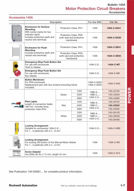
Accessories 140A
3-Pole Manual Motor Starters
Manual Motor Starters 140A
Product Selection
See Publication 140-SG001… for complete product information.
Description Term. No.For Use
With Cat. No.N.O. N.C.
Auxiliary Contact for FlushMounting1-poleNo additional space required
13-14 1 0
140A
140A-C-AEA10
33-34 1 0 140A-C-AEA210
11-12 0 1 140A-C-AEA01
31-32 0 1 140A-C-AEA201
Auxiliary Contact for Left-sideMounting2-poleAdds 9 mm to the width of theManual Motor StarterUse compact bus bars with54 mm spacing
13-1423-24 2 0
140A
140A-C-ASA20
13-1421-22 1 1 140A-C-ASA11
11-1221-22 0 2 140A-C-ASA02
� Current Range 0.1…16 A� Motor Protection� For Economical Motor Starters� Usable as Main Switch� Temperature Compensated� Standards and Approvals: IEC, cULus
RatedOperationalCurrent (Ie)
Motor CurrentAdjustment
Range
Switching of 3-Phase AC MotorsAC-2, AC-3 (50 Hz)
Cat. No.
[kW] � Icu = Ics [kA]
[A] [A] 400/415V 525V 400V 525V
0.16 0.1…0.16 0.02 0.02 65 50 140A-C2A-A16
0.25 0.16…0.25 0.06 0.06 65 50 140A-C2A-A25
0.4 0.25…0.4 0.09 0.09 65 50 140A-C2A-A40
0.63 0.4…0.63 0.12/0.18 0.18 65 50 140A-C2A-A63
1 0.63…1.0 0.25 0.37 65 50 140A-C2A-B10
1.6 1.0…1.6 0.37/0.55 0.75 65 50 140A-C2A-B16
2.5 1.6…2.5 0.75 1.1 50 4.5 140A-C2A-B25
4 2.5…4.0 1.1/1.5 2.2 10 3 140A-C2A-B40
6.3 4.0…6.3 2.2 3.0 10 3 140A-C2A-B63
10 6.3…10 3.0/4.0 6.3 8 3 140A-C2A-C10
16 10…16 5.5/7.5 10 6 3 140A-C2A-C16
� Power ratings: Preferred values according to IEC 60072-1

Bulletin 140AMotor Protection Circuit Breakers
1-6 Visit our website: www.ab.com/catalogs Rockwell Automation
PO
WE
R
Accessories 140A
Accessories
See Publication 140-SG001… for complete product information.
Description For Use With Cat. No.
Undervoltage Trip Release For right-side mountingAdds 18 mm to the width of theManual Motor Starter
24V 50 Hz
140A
140A-C-UXK
110V 50 / 60 Hz 140A-C-UXKD
110V 50 Hz / 120V 60 Hz 140A-C-UXD
220…230V 50 Hz 140A-C-UXF
400V 50 Hz / 460V 60 Hz 140A-C-UXN
415V 50 Hz / 480V 60 Hz 140A-C-UXB
525V 50 Hz / 600V 60 Hz 140A-C-UXVC
Shunt Trip ReleaseFor right-side mountingAdds 18 mm to the width of theManual Motor Starter
24V 50 Hz
140A
140A-C-SXK
110V 50 / 60 Hz 140A-C-SXKD
110V 50 Hz / 120V 60 Hz 140A-C-SXD
220…230V 50 Hz 140A-C-SXF
400V 50 Hz / 460V 60 Hz 140A-C-SXN
415V 50 Hz / 480V 60 Hz 140A-C-SXB
525V 50 Hz / 600V 60 Hz 140A-C-SXVC
Compact Bus Bars45 mm spacing for manual motorstarters with flush-mounted auxiliarycontact blocks
2 x 3 Terminal links
140A
140A-C-W452
3 x 3 Terminal links 140A-C-W453
4 x 3 Terminal links 140A-C-W454
5 x 3 Terminal links 140A-C-W455
Compact Bus Bars54 mm spacing for manual motorstarters with side-mounted auxiliarycontact blocks
2 x 3 Terminal links
140A
140A-C-W542
3 x 3 Terminal links 140A-C-W543
4 x 3 Terminal links 140A-C-W544
5 x 3 Terminal links 140A-C-W545
Bus Bar Feeder TerminalSupply of compact busbarsIncreases wiring capacity
140A-C-W 140A-C-WT
Blank Space CoverFor covering unused terminal links 140A-C-W 140A-C-WS
Bulletin 140AMotor Protection Circuit Breakers
1-7Visit our website: www.ab.com/catalogsRockwell Automation
PO
WE
R
Accessories 140A
See Publication 140-SG001… for complete product information.
Accessories
Description For Use With Cat. No.
Enclosures for SurfaceMountingWith centre marks for twoindicator lightsIncludes protective earth andneutral wire terminals
Protection Class: IP41 140A 140A-C-EA41
Protection Class: IP55(with seal and protective
membrane)140A 140A-C-EA55
Enclosures for FlushMountingIncludes protective earth andneutral wire terminals
Protection Class: IP41 140A 140A-C-EE41
Protection Class: IP55(with seal and protective
membrane)140A 140A-C-EE55
Emergency-Stop Push Button SetFor use with enclosuresTwist to release
140A-C-E… 140A-C-MT
Emergency-Stop Push Button SetFor use with enclosuresKey release
140A-C-E… 140A-C-MK
Button MembraneFor IP55 enclosuresReplacement part with four screws (mounting frameincluded)
140A-C-EA55140A-C-EE55 140A-C-N55
Pilot LightsLength of connection leads180 mm, includes lamp,protection class IP54.
Green
120V 198E-A…,198E-C…,
140A-C-E…
140-LG120
240V 140-LG240
400V 140-LG400
Red
120V 198E-A…,198E-C…,
140A-C-E…
140-LR120
240V 140-LR240
400V 140-LR400
White
120V 198E-A…,198E-C…,
140A-C-E…
140-LW120
240V 140-LW240
400V 140-LW400
Locking ArrangementSuitable for enclosures 140A-C-E…For 1…3 padlocks with ø 4…8 mm
140A-C-E… 140A-C-M3E
Locking ArrangementFor locking ON-button of the Manual Motor StarterFor 1…3 padlocks with ø 4…6 mm
140A 140A-C-M3
Screw AdapterHut (DIN) rail 35 x 7.5 mm, length 44 mm 140A 140A-C-N12

Bulletin 140MMotor Protection Circuit Breakers
1-8 Visit our website: www.ab.com/catalogs Rockwell Automation
PO
WE
R
Motor Protection Circuit Breakers 140M, 140-CMN
Product Selection
� Short Circuit Protection — Standard Magnetic Trip (13 x Ie max.)� Overload Protection — Trip Class 10� Ambient Temperature Compensation� Phase-loss Protection� ATEX for C- and D-Frame� Standards and Approvals: IEC, cULus
RatedOperationalCurrent (Ie)
MotorCurrent
AdjustmentRange
Switching of 3-Phase AC MotorsAC-2, AC-3 (50 Hz)
Cat. No.
[kW] Icu [kA]
[A] [A] 400V 525V 400V 525V
C-Frame
0.16 0.10…0.16 0.02 0.02 100 100 � 140M-C2E-A16
0.25 0.16…0.25 0.06 0.06 100 100 � 140M-C2E-A25
0.4 0.25…0.40 0.09 0.09 100 100 � 140M-C2E-A40
0.63 0.40…0.63 0.18 0.18 100 100 � 140M-C2E-A63
1 0.63…1.0 0.25 0.37 100 47 � 140M-C2E-B10
1.6 1.0…1.6 0.55 0.75 100 47 � 140M-C2E-B16
2.5 1.6…2.5 0.75 1.1 100 30 � 140M-C2E-B25
4 2.5…4.0 1.5 2.2 100 25 � 140M-C2E-B40
6.3 4.0…6.3 2.2 3 100 30 � 140M-C2E-B63
10 6.3…10 4 6.3 100 30 � 140M-C2E-C10
16 10…16 7.5 10 50 30 � 140M-C2E-C16
20 14.5…20 10 11 15 10 � 140M-C2E-C20
25 18…25 11 15 15 5 � 140M-C2E-C25
D-Frame
2.5 1.6…2.5 0.75 1.1 100 30 140M-D8E-B25
4 2.5…4.0 1.5 2.2 100 30 140M-D8E-B40
6.3 4.0…6.3 2.2 3 100 30 140M-D8E-B63
10 6.3…10 4 6.3 100 30 140M-D8E-C10
16 10…16 7.5 10 100 30 140M-D8E-C16
20 14.5…20 10 11 65 30 140M-D8E-C20
25 18…25 11 15 65 30 140M-D8E-C25
F-Frame
10 6.3…10 4 .6.3 65 30 140M-F8E-C10
16 10…16 7.5 10 65 30 140M-F8E-C16
20 14.5…20 10 11 65 30 140M-F8E-C20
25 18…25 11 15 65 30 140M-F8E-C25
32 23…32 15 20 65 30 140M-F8E-C32
45 32…45 22 30 65 18 140M-F8E-C45
CMN-Frame
25 16…25 13 15 65 42 140-CMN-2500
40 25…40 22 25 65 42 140-CMN-4000
63 40…63 32 40 65 18 140-CMN-6300
90 63…90 45 55 50 10 140-CMN-9000
� May be ordered in package quantities of 20. Add letter M to the end of the cat. no. (Example: 140M-C2E-A16M).

Bulletin 140MMotor Protection Circuit Breakers
1-9Visit our website: www.ab.com/catalogsRockwell Automation
PO
WE
R
Motor Protection Circuit Breakers 140M-I, -J, -L
Product Selection
Cat. No. 140M-I Cat. No. 140M-J Cat. No. 140M-L
� Short Circuit Protection — Standard Magnetic Trip (Fixed at 12...15 x Ie)� Overload Protection — Trip Class: 140M-I, 5…20 / 140M-J, -L, 10…30 (Adjustable)� UL/CSA, IEC, CE
Rated OperationalCurrent (Ie)
Motor CurrentAdjustment Range Ultimate Interrupting Current [kA] (Icm)
Cat. No.[A] [A] 400V 525V
I-Frame
80 40…80 70 30 � 140M-I8E-C80E
100 80…100 70 30 � 140M-I8E-D10E
160 100…160 70 30 � 140M-I8E-D16E
205 160…205 70 30 � 140M-I8E-D20E
J-Frame
50 20…50 25 18 140M-J2E-C50
100 40…100 25 18 140M-J2E-D10
160 64…160 25 18 140M-J2E-D16
250 100…250 25 18 140M-J2E-D25
50 20…50 70 25 140M-J8E-C50
100 40…100 70 25 140M-J8E-D10
160 64…160 70 25 140M-J8E-D16
250 100…250 70 25 140M-J8E-D25
L-Frame
250 100…250 40 18 140M-L2E-D25
400 160…400 40 18 140M-L2E-D40
630 250…630 40 18 140M-L2E-D63
250 100…250 70 25 140M-L8E-D25
400 160…400 70 25 140M-L8E-D40
630 250…630 70 25 140M-L8E-D63
� IEC approvals and CE marking onlyAccessories for 140M-I, -J, -L see page 1-22, catalogue A116 or on-line catalogue at www.ab.com/catalogs

Bulletin 140MMotor Circuit Protectors
1-10 Visit our website: www.ab.com/catalogs Rockwell Automation
PO
WE
R
Product Selection
Circuit Breakers 140M, Short-Circuit Protection for Starters
� Short Circuit Protection — Standard Magnetic Trip (Ii=13 x Ie max.)� Instantaneous Trip Circuit Breakers (ICB) ‡� For Trip Class 10 Motor Applications �� Standards and Approvals: IEC, cULus, UL 508
Rated OperationalCurrent (Ie)
Switching of 3-Phase AC MotorsAC-2, AC-3 (50 Hz)
Cat. No.
[kW] Icu [kA]
[A] 400V 525V 400V 525V
C-Frame
0.16 0.02 0.02 100 100 � 140M-C2N-A16
0.25 0.06 0.06 100 100 � 140M-C2N-A25
0.4 0.09 0.09 100 100 � 140M-C2N-A40
0.63 0.18 0.18 100 100 � 140M-C2N-A63
1 0.25 0.37 100 100 � 140M-C2N-B10
1.6 0.55 0.75 100 47 � 140M-C2N-B16
2.5 0.75 1.1 100 47 � 140M-C2N-B25
D-Frame
2.5 0.75 1.1 100 30 � 140M-D8N-B25
4 1.5 2.2 100 30 � 140M-D8N-B40
6.3 2.2 3 100 30 � 140M-D8N-B63
10 4 6.3 100 30 � 140M-D8N-C10
16 7.5 10 100 30 � 140M-D8N-C16
25 11 15 65 30 � 140M-D8N-C25
F-Frame
25 11 15 65 30 140M-F8N-C25
32 15 20 65 30 140M-F8N-C32
45 22 30 65 18 140M-F8N-C45
� May be ordered in package quantities of 20. Add letter M to the end of the cat. no. (Example: 140M-C2N-A16M).� For Heavy Duty (exceeding Trip Class 10) starting applications, please please consult your local sales office.‡ Instantaneous Trip Circuit Breakers (ICB) according to IEC-60947-2, Ed. 4, Annex 0Accessories see page 1-12

Bulletin 140MMotor Circuit Protectors
1-11Visit our website: www.ab.com/catalogsRockwell Automation
PO
WE
R
Product Selection
Cat. No. 140M-H Cat. No. 140M-J Cat. No. 140M-L
� Short Circuit Protection — Magnetic Trip (Adjustable at 3...10 x Ie)� Overload Protection — None (Magnetic Trip Only)� Standards and Approvals: IEC, cULus, UL 489
Motor Circuit Protectors (MCP)
Rated OperationalCurrent (Ie)
Magnetic Trip CurrentRange
Switching of 3-Phase AC MotorsAC-2, AC-3 (50 Hz)
Cat. No.
[kW] � Icu [kA]
[A] [A] 400V 525V 400V 525V
H-Frame
3 9…33 0.75 1.1 65 25 140M-H8P-B30
7 21…77 2.2 3 65 25 140M-H8P-B70
15 45…165 5.5 7.5 65 25 140M-H8P-C15
30 90…330 11 15 65 25 140M-H8P-C30
50 150…550 22 22 65 25 140M-H8P-C50
70 210…770 30 37 65 25 140M-H8P-C70
100 300…1100 45 55 65 25 140M-H8P-D10
100 500…1500 55 75 65 25 140M-H8R-D10
J-Frame
100 500…1000 37 45 65 25 140M-J8P-D10
125 625…1250 45 55 65 25 140M-J8P-D12
150 750…1500 55 75 65 25 140M-J8P-D15
175 875…1750 55 90 65 25 140M-J8P-D17
200 1000…2000 75 90 65 25 140M-J8P-D20
225 1125…2250 90 110 65 25 140M-J8P-D22
250 1250…2500 90 132 65 25 140M-J8P-D25
L-Frame
225 1125…2250 90 110 65 25 140M-L8P-D22
250 1250…2500 90 132 65 25 140M-L8P-D25
300 1500…3000 110 160 65 25 140M-L8P-D30
350 1750…3500 132 160 65 25 140M-L8P-D35
400 2000…4000 160 200 65 25 140M-L8P-D40
450 2250…4500 160 200 65 25 140M-L8P-D45
500 2500…5000 200 250 65 25 140M-L8P-D50
600 3000…6000 250 315 65 25 140M-L8P-D60
N-Frame
800 1600…6400 250 355 65 35 140M-N8P-D80
1200 2400…9600 400 500 65 35 140M-N8P-E12
� The kW ratings shown are for reference only.Accessories for 140M-H, -J, -L, N see page 1-22

Bulletin 140MMotor Protection Circuit Breakers
1-12 Visit our website: www.ab.com/catalogs Rockwell Automation
PO
WE
R
Accessories 140M, 140-CMN
Accessories
DescriptionTerm.No. For Use With Cat. No.N.O. N.C.
Front-Mounted AuxiliaryContact1-pole or 2-poleNo additional spacerequired-One only per MPCB
13-14 1 0 140M-C, D, F � 140M-C-AFA10
11-12 0 1 140M-C, D, F 140M-C-AFA01
13-141 1 140M-C, D, F � 140M-C-AFA11
21-22
13-142 0 140M-C, D, F 140M-C-AFA20
23-24
11-120 2 140M-C, D, F 140M-C-AFA02
21-22
Right Side-MountedAuxiliary Contact2-poleAdds 9 mm to the width ofthe device-Two per MPCB
33-342 0 140M-C, D, F 140M-C-ASA20
43-44
31-320 2 140M-C, D, F 140M-C-ASA02
41-42
33-341 1 140M-C, D, F � 140M-C-ASA11
41-42
Front-Mounted TripContact2-poleIndicates tripping of deviceNo additional spacerequired
13-142 0 140M-C, D, F 140M-C-AFAR10A10
27-28
11-121 1 140M-C, D, F 140M-C-AFAR10A01
27-28
Right-Side Mounted TripContact2-poleIndicates tripping of MotorProtection Circuit BreakerAdds 9 mm to the width ofthe circuit breaker-One only per MPCB-A right-side mountedauxiliary contact may betandem mounted on top ofthis Trip Contact
57-582 0 140M-C, D, F 140M-C-ASAR10M10
67-68
57-581 1 140M-C, D, F 140M-C-ASAR10M01
65-66
55-561 1 140M-C, D, F 140M-C-ASAR01M10
67-68
55-560 2 140M-C, D, F 140M-C-ASAR01M01
65-66
77-781 1 140M-C, D, F 140M-C-ASAM11
65-66
Front-Mounted AuxiliaryContactInternal2-pole-One per MPCB
13-142 0 140-CMN 140-CA20
23-24
11-120 2 140-CMN 140-CA02
21-22
13-141 1 140-CMN 140-CA11
21-22
Front-Mounted Trip-Indicating AuxiliaryContactInternal2-pole-One per MPCB
37-382 0 140-CMN 140-CT10-10
43-44
35-360 2 140-CMN 140-CT01-01
41-42
35-361 1 140-CMN 140-CT01-10
43-44
37-381 1 140-CMN 140-CT10-01
41-42
� May be ordered in package quantities of 10. Add letter M to the end of the cat. no. (Example: 140M-C-AFA10M).

Bulletin 140MMotor Protection Circuit Breakers
1-13Visit our website: www.ab.com/catalogsRockwell Automation
PO
WE
R
Accessories 140M, 140-CM
Accessories
Description Trip Rating For Use With Cat. No.
Undervoltage TripLeft-side mountedAdds 18 mm to the width of thecircuit breakerAutomatically trips MPCB/MCPwhen voltage falls below 35…70%
24V, 50 Hz
140M-C, D, F
140M-C-UXK
110V, 50 Hz 140M-C-UXC
220…230V, 50 Hz 140M-C-UXF
380…400V, 50 Hz 140M-C-UXN
480V, 60 Hz/415V, 50 Hz 140M-C-UXB
575V, 60 Hz/500V, 50 Hz 140M-C-UXM
Undervoltage TripLeft-side mountedTwo early make contacts integratedAdds 18 mm to the width of thecircuit breakerAutomatically trips MPCB/MCPwhen voltage falls below 35…70%
24V, 50 Hz
140M-C, D, F
140M-C-UCK
110V, 50 Hz 140M-C-UCC
220…230V, 50 Hz 140M-C-UCF
380…400V, 50 Hz 140M-C-UCN
480V, 60 Hz/415V, 50 Hz 140M-C-UCB
575V, 60 Hz/500V, 50 Hz 140M-C-UCM
Shunt TripLeft-side mountedAdds 18 mm to the width of thecircuit breakerTrips motor protector when voltageis removed
24V, 50 Hz
140M-C, D, F
140M-C-SNK
110V, 50 Hz 140M-C-SNC
220…230V, 50 Hz 140M-C-SNF
380…400V, 50 Hz 140M-C-SNN
480V, 60 Hz/415V, 50 Hz 140M-C-SNB
575V, 60 Hz/500V, 50 Hz 140M-C-SNM
Undervoltage Trip UnitInternal, front-mountedIntegrated short-circuit trip indicationAutomatically trips MPCB whenvoltage falls below 35…70%
24V, 50/60 Hz
140-CMN
140-CUV-KJ
110V, 50 Hz/120V, 60 Hz 140-CUV-D
220V, 50 Hz/240V, 60 Hz 140-CUV-A
Shunt Trip UnitInternal, front-mountedIntegrated short-circuit trip indicationProvides remote tripping of theMPCB
24V, 50/60 Hz
140-CMN
140-CRT-KJ
110V, 50 Hz/120V, 60 Hz 140-CRT-D
220V, 50 Hz/240V, 60 Hz 140-CRT-A
Communication ModuleDeviceNet Starter Auxiliary DSA I/O for Distributed Starters, see page 1-35

Bulletin 140MMotor Protection Circuit Breakers
1-14 Visit our website: www.ab.com/catalogs Rockwell Automation
PO
WE
R
Accessories 140M, 140-CM
Accessories
Description For Use With Cat. No.
Lockable Twist KnobFor one padlock 4…6 mm (1/4 in.) dia.shackleCan be locked in OFF position
Black 140M-C, D, F 140M-C-KN
Red/Yellow 140M-C/-D 140M-C-KRY
Red/Yellow 140M-F 140M-F-KRY
Padlockable Operating KnobAccepts 8 mm (5/16 in.) dia. padlock — up tothree padlocksPermits padlocking in the off position
Black
140-CMN
140-KN
Red/Yellow 140-KRY
Door Coupling HandleFor three padlocks 4…8 mm (5/16 in.) dia.IP66 Protection/Type 1, 4, 4X, 12Interlock override capabilityCan be modified for locking in ON positionShips with coupling — order extension shaft
and legend plate separatelyMounting depth (front of DIN Rail to front ofenclosure door):140M-C: 105.5 mm ± 5 mm (4.15 in. ± 3/16in.)140M-D: 114.5 mm ± 5 mm (4.5 in. ± 3/16 in.)140M-F: 137.1 mm ± 5 mm (5.4 in. ± 3/16 in.)140-CMN: 169 mm +/- 5 mm (6.7 in. +/- 3/16in.)
Black
140M-C, D, F 140M-C-DN66
140-CMN 140-CDN66
Red/Yellow
140M-C, D, F 140M-C-DRY66
140-CMN 140-CDRY66
Extension ShaftCut to required length for mounting depth (front of DIN Rail tofront of enclosure door):140M-C: 117…338 mm (4.6.…13.3 in.)140M-D: 126…347 mm (5.0.…13.7 in.)140M-F: 149…369 mm (5.9.…14.5 in.)140-CMN: 180…403 mm (7.1.…15.9 in.)
140M-C-DN66,
140M-C-DRY66,
140-CDN66,140-CDRY66
140M-C-DS
140M-C: 117...488 mm (4,6...19,2 in.)140M-D: 126...497 mm (5,0...19,6 in.)140M-F: 149...519 mm (5,4...20,4 in.)140-CMN: 180...553 mm (7,1...21,8 in.)
140M-C-DSL
Legend PlateMarking: "Hauptschalter" and "Main Switch"Marking: "Not-Aus" and "Emergency Off"
140-CDN66 140M-C-DFCN
140-CDRY66 140M-C-DFCRY
Locking TagPadlock attachment to the lockable handlesUp to three padlocks 4…8 mm (5/16 in.) dia. shackle
140M-C-KN140M-C-KRY140M-F-KRY
140M-C-M3
Anti-Tamper ShieldProvides protection against inadvertent adjustment of thecurrent settingPackage quantity = 10 �
140M-C, D, F 140M-C-CA
� Sold only in multiples of 10. Order (quantity of) 10 to receive one package of 10 pieces.

Bulletin 140MMotor Protection Circuit Breakers
1-15Visit our website: www.ab.com/catalogsRockwell Automation
PO
WE
R
Accessories
Accessories 140M
Description For Use With Cat. No.
ECO Connecting Module — 12 AFor DOL and reversing startersEco-starters mount on single DIN Rail (140M onDIN Rail)Electrical and mechanical interconnection of140M MPCB and 100-K contactors
140M-C to 100-K � 140M-C-PEK12
ECO Connecting Modules — 25 AEco-starters mount on single DIN Rail (140M onDIN Rail)Electrical and mechanical interconnection of140M MPCB and 100-C (with AC coils or 24V DCelectronic coils) contactors
140M-C to 100-C09…C23 � 140M-C-PEC23
140M-D to 100-C09…C23 � 140M-D-PEC23
ECO Connecting Modules — 25 AEco-starters mount on single DIN Rail (100-C onDIN Rail)Electrical and mechanical interconnection of140M MPCB and 100-C (with AC or DC coils)
140M-C, 140M-Dto 100-C09…C23
‡� 140M-C-PEC23A
Connecting Modules — 25 and 45 AContactor and MPCB MUST BE mountedseparately on (2) DIN RailsElectrical interconnection between 140M MPCBand 100-C contactors (with AC coils)
140M-C to 100-C09…C23 140M-C-PNC23
140M-D to 100-C09…C23 140M-D-PNC23
140M-D to 100-C30…C37 140M-D-PNC37
140M-F to 100-C30…C37 140M-F-PNC37
140M-F to 100-C43 140M-F-PNC43
Flexible Connecting Module — 22 A (25 A)Flexible electrical interconnection. Allows variablespacing between 140M MPCB and 100-Ccontactor (with AC or DC coils: 105…145 mmDIN Rail spacing with AC coils, 105…125 mmwith DC coils)
140M-C, 140M-Dto 100-C09…C43 140M-D-PFC23DM
Spacing AdapterRequired for Self-Protected combination motorcontroller (Type E) applicationsof Bul. 140M-C, -D, and -F MPCBs
140M-C, -D 140M-C-TE1
140M-F 140M-F-TE
Screw AdapterFor screw arrangement of a Motor ProtectionCircuit BreakerPackage quantity = 10 §
140M-C, D, F 140M-C-N45
IP65 Non-Metallic EnclosureKnockouts for M20 and M25 fittingsSuitable for flexible cable withinternal ground wire or conduitwhen externally grounded aroundthe outside of the enclosure (no ULapproval)
BlackHandle 140M-C 198E-AYTG2
Red/YellowHandle 140M-C 198E-AYTJ2
� May be ordered in package quantities of 10. Add letter M to the end of the cat. no. (Example: 140M-C-PEK12M).�May be ordered in package quantities of 20. Add letter M to the end of the cat. no. (Example: 140M-C-PEC23M).
Bulletin 140MMotor Protection Circuit Breakers
1-16 Visit our website: www.ab.com/catalogs Rockwell Automation
PO
WE
R
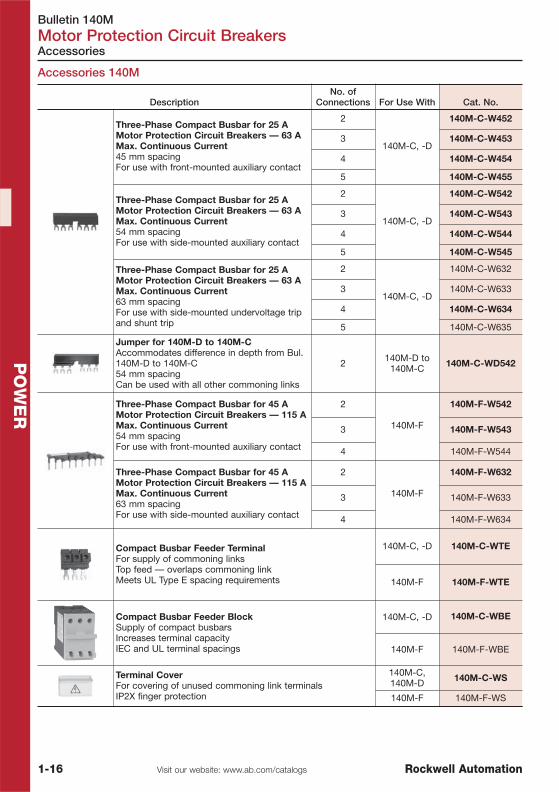
Accessories 140M
Accessories
DescriptionNo. of
Connections For Use With Cat. No.
Three-Phase Compact Busbar for 25 AMotor Protection Circuit Breakers — 63 AMax. Continuous Current45 mm spacingFor use with front-mounted auxiliary contact
2
140M-C, -D
140M-C-W452
3 140M-C-W453
4 140M-C-W454
5 140M-C-W455
Three-Phase Compact Busbar for 25 AMotor Protection Circuit Breakers — 63 AMax. Continuous Current54 mm spacingFor use with side-mounted auxiliary contact
2
140M-C, -D
140M-C-W542
3 140M-C-W543
4 140M-C-W544
5 140M-C-W545
Three-Phase Compact Busbar for 25 AMotor Protection Circuit Breakers — 63 AMax. Continuous Current63 mm spacingFor use with side-mounted undervoltage tripand shunt trip
2
140M-C, -D
140M-C-W632
3 140M-C-W633
4 140M-C-W634
5 140M-C-W635
Jumper for 140M-D to 140M-CAccommodates difference in depth from Bul.140M-D to 140M-C54 mm spacingCan be used with all other commoning links
2 140M-D to140M-C 140M-C-WD542
Three-Phase Compact Busbar for 45 AMotor Protection Circuit Breakers — 115 AMax. Continuous Current54 mm spacingFor use with front-mounted auxiliary contact
2
140M-F
140M-F-W542
3 140M-F-W543
4 140M-F-W544
Three-Phase Compact Busbar for 45 AMotor Protection Circuit Breakers — 115 AMax. Continuous Current63 mm spacingFor use with side-mounted auxiliary contact
2
140M-F
140M-F-W632
3 140M-F-W633
4 140M-F-W634
Compact Busbar Feeder TerminalFor supply of commoning linksTop feed — overlaps commoning linkMeets UL Type E spacing requirements
140M-C, -D 140M-C-WTE
140M-F 140M-F-WTE
Compact Busbar Feeder BlockSupply of compact busbarsIncreases terminal capacityIEC and UL terminal spacings
140M-C, -D 140M-C-WBE
140M-F 140M-F-WBE
Terminal CoverFor covering of unused commoning link terminalsIP2X finger protection
140M-C,140M-D 140M-C-WS
140M-F 140M-F-WS
Bulletin 140UEMolded Case Circuit Breakers
1-17Visit our website: www.ab.com/catalogsRockwell Automation
PO
WE
R
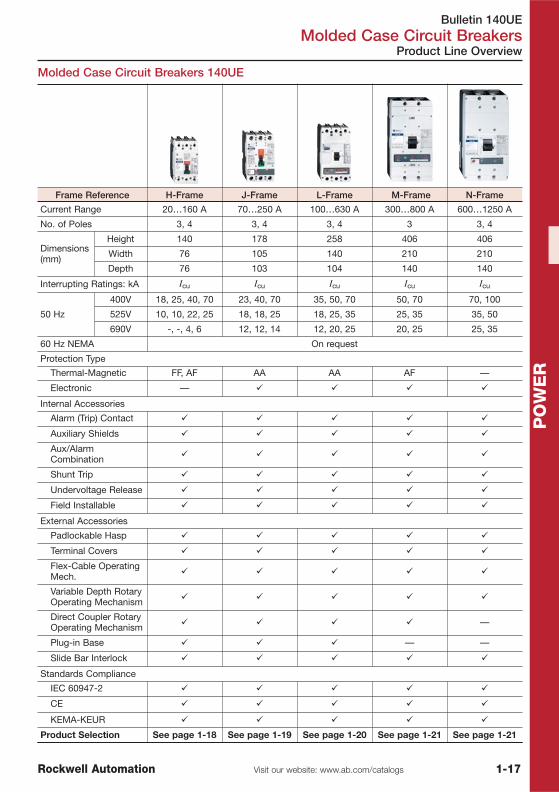
Molded Case Circuit Breakers 140UE
Product Line Overview
Frame Reference H-Frame J-Frame L-Frame M-Frame N-Frame
Current Range 20…160 A 70…250 A 100…630 A 300…800 A 600…1250 A
No. of Poles 3, 4 3, 4 3, 4 3 3, 4
Dimensions(mm)
Height 140 178 258 406 406
Width 76 105 140 210 210
Depth 76 103 104 140 140
Interrupting Ratings: kA Icu Icu Icu Icu Icu
50 Hz
400V 18, 25, 40, 70 23, 40, 70 35, 50, 70 50, 70 70, 100
525V 10, 10, 22, 25 18, 18, 25 18, 25, 35 25, 35 35, 50
690V -, -, 4, 6 12, 12, 14 12, 20, 25 20, 25 25, 35
60 Hz NEMA On request
Protection Type
Thermal-Magnetic FF, AF AA AA AF —
Electronic — � � � �
Internal Accessories
Alarm (Trip) Contact � � � � �
Auxiliary Shields � � � � �
Aux/AlarmCombination � � � � �
Shunt Trip � � � � �
Undervoltage Release � � � � �
Field Installable � � � � �
External Accessories
Padlockable Hasp � � � � �
Terminal Covers � � � � �
Flex-Cable OperatingMech. � � � � �
Variable Depth RotaryOperating Mechanism � � � � �
Direct Coupler RotaryOperating Mechanism � � � � —
Plug-in Base � � � — —
Slide Bar Interlock � � � � �
Standards Compliance
IEC 60947-2 � � � � �
CE � � � � �
KEMA-KEUR � � � � �
Product Selection See page 1-18 See page 1-19 See page 1-20 See page 1-21 See page 1-21

Bulletin 140UEMolded Case Circuit Breakers
1-18 Visit our website: www.ab.com/catalogs Rockwell Automation
PO
WE
R
Product Selection
Circuit Breakers 140UE — 160 A, H-Frame
� Thermal Magnetic Trip� 18, 25, 40, 70 kA Breaking Capacity @ 415V (50 Hz)� 3-pole, 4-poleApprovals� IEC 60947-2, CE, KEMA-KEUR
Note: Terminal box lugs and mounting hardware provided as standard
25 kA, Thermal-Magnetic, Adjustable Thermal-Fixed Magnetic
Isolation Disconnector — IEC 60947-3
See Publication 140UE-SG001… for 4-pole types and different breaking capacity.
RatedOperationalCurrent (In)
Thermal Trip(Ir = 0.8…1.0 x In)
Magnetic Trip(Im = 10 x In)
Breaking Capacity (50 Hz)Icu /Ics [kA] 3-Pole
[A] [A] [A] 400V 525V 690V � Cat. No.
20 16…20 500 25 13 10 5 — — 140UE-H2E3-C20
25 20…25 500 25 13 10 5 — — 140UE-H2E3-C25
32 25…32 500 25 13 10 5 — — 140UE-H2E3-C32
40 32…40 500 25 13 10 5 — — 140UE-H2E3-C40
50 40…50 500 25 13 10 5 — — 140UE-H2E3-C50
63 50…63 630 25 13 10 5 — — 140UE-H2E3-C63
80 63…80 800 25 13 10 5 — — 140UE-H2E3-C80
100 80…100 1000 25 13 10 5 — — 140UE-H2E3-D10
125 100…125 1250 25 13 10 5 — — 140UE-H2E3-D12
160 125…160 1600 25 13 10 5 — — 140UE-H2E3-D16
� For 690V applications refer to 140UE-H4E3 / 140UE-H7E3
RatedOperationalCurrent (In)
Thermal Trip(Ir = In), Fixed
Magnetic Trip(Im = 10 x In)
Breaking Capacity (50 Hz)Icu /Ics [kA] 3-Pole
[A] [A] [A] 400V 525V 690V Cat. No.160 — 1600 25 25 3 3 3 3 140UE-H2S3-D16

Bulletin 140UEMolded Case Circuit Breakers
1-19Visit our website: www.ab.com/catalogsRockwell Automation
PO
WE
R
Product Selection
Circuit Breakers 140UE — 250 A, J-Frame
� Thermal Magnetic Trip� Electronic Trip LS, LSI, LSG and LSIG� 25, 40, 70 kA Breaking Capacity @ 415V (50 Hz)� 3-pole, 4-poleApprovals� IEC 60947-2, CE, KEMA-KEUR
40 kA, Assembled Circuit Breakers, Thermal-Magnetic Trip Units
Isolation Disconnector — IEC 60947-3
See Publication 140UE-SG001… for 4-pole types, electronic trip units and different breakingcapacity.
RatedOperationalCurrent (In)
Thermal Trip(Ir = 0.8…1.0 x In)
Magnetic Trip(Im = 5…10 x In)
Breaking Capacity (50 Hz)Icu /Ics [kA] 3-Pole
[A] [A] [A] 400V 525V 690V Cat. No.
80 64…80 400…800 40 40 18 10 12 6 140UE-J4F3-C80
100 80…100 500…1000 40 40 18 10 12 6 140UE-J4F3-D10
125 100…125 625…1250 40 40 18 10 12 6 140UE-J4F3-D12
160 128…160 800…1600 40 40 18 10 12 6 140UE-J4F3-D16
200 160…200 1000…2000 40 40 18 10 12 6 140UE-J4F3-D20
250 200…250 1250…2500 40 40 18 10 12 6 140UE-J4F3-D25
RatedOperationalCurrent (In)
Thermal Trip(Ir = 0.8…1.0 x In)
Magnetic Trip(Im = 10 x In)
Breaking Capacity (50 Hz)Icu /Ics [kA] 3-Pole
[A] [A] [A] 400V 525V 690V Cat. No.250 — 2500 70 70 25 10 14 7 140UE-J7S3-D25

Bulletin 140UEMolded Case Circuit Breakers
1-20 Visit our website: www.ab.com/catalogs Rockwell Automation
PO
WE
R
Product Selection
Circuit Breakers 140UE — 630 A, L-Frame
Circuit breakers can be assembled from a circuit breaker frame and atrip unit, or purchased as assembled units.
� Thermal Magnetic Trip� Electronic Trip LS, LSI, LSG and LSIG� 35, 50, 70 kA Breaking Capacity @ 415V (50 Hz)� 3-pole, 4-poleApprovals� IEC 60947-2, CE, KEMA-KEUR
50 kA, Assembled Circuit Breakers, Thermal-Magnetic Trip Units
50 kA, Assembled Circuit Breakers, Electronic Trip Units
Isolation Disconnector — IEC 60947-3
See Publication 140UE-SG001… for 4-pole types and different breaking capacity.
RatedOperationalCurrent (In)
Thermal Trip(Ir = 0.8…1.0 x In)
Magnetic Trip(Im = 5…10 x In)
Breaking Capacity (50 Hz)Icu /Ics [kA] 3-Pole
[A] [A] [A] 400V 525V 690V Cat. No.
250 200…250 1250…2500 50 50 25 25 20 10 140UE-L5F3-D25
320 256…320 1600…3200 50 50 25 25 20 10 140UE-L5F3-D32
400 320…400 2000…4000 50 50 25 25 20 10 140UE-L5F3-D40
500 400…500 2500…5000 50 50 25 25 20 10 140UE-L5F3-D50
630 504…630 3150…6300 50 50 25 25 20 10 140UE-L5F3-D63
RatedOperationalCurrent (In)
Adjustment Range [A]
ProtectionType
Breaking Capacity (50 Hz)
3-PoleThermal TripIr = 0.4…1.0 x In
Magnetic TripIm = 2…10 x In
Icu /Ics [kA]
400V 525V 690V Cat. No.
630 250…630 1260…6300 LS 50 50 25 25 20 10 140UE-L5L3-D63
630 250…630 1260…6300 LSI 50 50 25 25 20 10 140UE-L5H3-D63
630 250…630 1260…6300 LSG � 50 50 25 25 20 10 140UE-L5G3-D63
630 250…630 1260…6300 LSIG � 50 50 25 25 20 10 140UE-L5I3-D63
� Ground Fault Functions: IG = 0.2…1.0 In
RatedOperationalCurrent (In)
Thermal Trip(Ir = In)
Magnetic Trip(Im = 10 x In)
Breaking Capacity (50 Hz)Icu /Ics [kA] 3-Pole
[A] [A] [A] 400V 525V 690V Cat. No.630 — 6300 70 70 32 32 25 13 140UE-L7S3-D63

Bulletin 140UEMolded Case Circuit Breakers
1-21Visit our website: www.ab.com/catalogsRockwell Automation
PO
WE
R
Product Selection
Circuit Breakers 140UE — 800 A, M-Frame
� Thermal Magnetic Trip� Electronic Trip LS, LSI, LSG and LSIG� 50, 70 kA Breaking Capacity @ 415V (50 Hz)� 3-poleApprovals� IEC 60947-2, CE, KEMA-KEUR
50 kA, Assembled Circuit Breakers, Electronic Trip Units
See Publication 140UE-SG001… for 4-pole types, thermal magnetic trip units and different breakingcapacity.
Circuit Breakers 140UE — 1250 A, N-Frame
� Electronic Trip LS, LSI, LSG and LSIG� 70 kA, 100 kA Breaking Capacity @ 415V (50 Hz)� 3-pole, 4-poleApprovals� IEC 60947-2, CE, KEMA-KEUR
70 kA, Assembled Circuit Breakers, Electronic Trip Units
Isolation Disconnector — IEC 60974-3
See Publication 140UE-SG001… for 4-pole types and different breaking capacity.
Note: Terminal box lugs and mounting hardware must be ordered separately.See page 1-23 or publication 140UE-SG001…
RatedOperationalCurrent (In)
Adjustment Range [A]
ProtectionType
Breaking Capacity (50 Hz)
3-PoleThermal TripIr = 0.4…1.0 x In
Magnetic TripIm = 2…10 x In
Icu /Ics [kA]
400V 525V 690V Cat. No.
800 A 400…800 800…6400
LS 50 50 25 25 20 10 140UE-M5L3-D80
LSI 50 50 25 25 20 10 140UE-M5H3-D80
LSG � 50 50 25 25 20 10 140UE-M5G3-D80
LSIG � 50 50 25 25 20 10 140UE-M5I3-D80
� Ground Fault Functions: IG = 0.2…1.0 In
RatedOperational
Current In [A]
Adjustment Range Ir [A]
ProtectionType
Breaking Capacity (50 Hz)3-PoleThermal Trip
Ir = 0.5…1.0 x In
Magnetic TripIm = 2…8 x In
Icu /Ics [kA]
400V 525V 690V Cat. No.
1250 600…1250 2400..10000
LS 70 50 35 18 25 13 140UE-N7L3-E12
LSI 70 50 35 18 25 13 140UE-N7H3-E12
LSG 70 50 35 18 25 13 140UE-N7G3-E12
LSIG 70 50 35 18 25 13 140UE-N7I3-E12
RatedOperational
Current In [A]Magnetic Trip
(10 x In)
Breaking Capacity (50 Hz)Icu /Ics [kA] 3-Pole
400V 525V 690V Cat. No.
1250 12500 70 50 35 18 25 13 140UE-N7S3-E12

Bulletin 140UEMolded Case Circuit Breakers
1-22 Visit our website: www.ab.com/catalogs Rockwell Automation
PO
WE
R
Accessories
Internal Accessories — Field Installed
Description Frame Size Cat. No.
Auxiliary Contact (AX)Electrically indicates "ON/OFF" status ofbreakers
1 C/O
H, J, L 140U-H-EA1
M 140U-M-EA1
N 140U-N-EA1
2 C/O
H, J, L 140U-H-EA2
M 140U-M-EA2
N 140U-N-EA2
Alarm Contact (AL)Electrically indicates when the breaker isin the "TRIPPED" state
1 C/O (E.M./L.B.)
H 140U-H-ER1
J, L 140U-J-ER1
M 140U-M-ER1
N 140U-N-ER1
Auxiliary/Alarm Contact (AX/AL)CombinationCombination of auxiliary contact andalarm contact
1 C/O (E.M./L.B.)
H 140U-H-EA1R1
J, L 140U-J-EA1R1
M 140U-M-EA1R1
N 140U-N-EA1R1
Shunt Trip (SNT)Provides remote tripping of the circuitbreakerUndervoltage trip not available whenshunt trip is used
24…60 V, 50/60/DC
H, J, L
140U-H-SNJ
110…240V, 50/60/DC 140U-H-SND
380…440V AC,220…250V DC 140U-H-SNN
380…600V, 50/60 Hz 140U-H-SNB
12…24V, 50/60/DC
M
140U-M-SNJ
110…240V AC,110…125V DC 140U-M-SND
380…440V AC,220…250V DC 140U-M-SNN
480…600V, 50/60 Hz 140U-M-SNB
12…24V, 50/60/DC
N
140U-N-SNJ
110…240V AC 140U-N-SND
380…440V AC,220…250V DC 140U-N-SNN
480…600V, 50/60 Hz 140U-N-SNB
Undervoltage Release (UVT)Automatically trips breaker when voltagefalls between preset value, 35…70%Shunt trip is not available whenundervoltage release is used
24V, 50/60Hz AC; 24VDC
H, J, L
140U-H-UJ
110…127V, 50/60 Hz 140U-H-UD
208…240V, 50/60 Hz 140U-H-UA
380…500V, 50/60 Hz 140U-H-UB
525…600V, 50/60 Hz 140U-H-UC
24V, 50/60 Hz
M
140U-M-UJ
110…127V, 50/60 Hz 140U-M-UD
208…240V, 50/60 Hz 140U-M-UA
380…500V, 50/60 Hz 140U-M-UB
24V, 50/60 Hz
N
140U-N-UJ
110…127V, 50/60 Hz 140U-N-UD
208…240V, 50/60 Hz 140U-N-UA
380…500V, 50/60 Hz 140U-N-UB

Bulletin 140UEMolded Case Circuit Breakers
1-23Visit our website: www.ab.com/catalogsRockwell Automation
PO
WE
R
Accessories
External Accessories
Description Frame Size PQ Cat. No.
Terminal ShieldsIP20 Ingress Protection Rating
3-PoleMCCBs
H
1
140U-H-TS
I 140U-I-TS1
J 140U-J-TS
L 140U-L-TS
Phase BarriersProvides additional phase clearance whenspecial connections that extend past thecircuit breaker housing are required
3-PoleMCCBs
H
2
140U-H-PB
I 140U-I-PB
J 140U-J-PB
L 140U-L-PB
M 140U-M-PB
N 140U-N-PB
Rotary, Direct Couple OperatingMechanismRotary handle - IP42 UL Type 1 Breaker mounted
Black Handle
H
1
140U-H-RCB
I 140U-I-RCB
J 140U-J-RCB
L 140U-L-RCB
Red/YellowHandle
H
1
140U-H-RCR
J 140U-J-RCR
L 140U-L-RCR
Rotary, Variable-Depth OperatingMechanismRotary handle - IP66, UL Type 3/12/4/4X12 in. (30.48 cm) operating rodOperating rod 30.5 cm
Black Handle
H
1
140U-H-RVM12B
J 140U-J-RVM12B
L 140U-L-RVM12B
M 140U-M-RVM12B
N 140U-N-RM12B
Red/YellowHandle
H
1
140U-H-RVM12R
J 140U-J-RVM12R
L 140U-L-RVM12R
M 140U-M-RVM12R
Rotary, Variable-Depth OperatingMechanismRotary handle - IP66, UL Type 3/12/4/4X21 in. (53.34 cm) operating rodOperating rod 53 cm
Black Handle
H
1
140U-H-RVM21B
J 140U-J-RVM21B
L 140U-L-RVM21B
M 140U-M-RVM21B
Red/YellowHandle
H
1
140U-H-RVM21R
J 140U-J-RVM21R
L 140U-L-RVM21R
M 140U-M-RVM21R
End Cap KitProvides three-phase connections forterminal or bolt-on connectionsMetric hardware provided
3-PoleMCCBs
H 1 140U-H-ECM
I 1 140U-I-ECM
J 1 140U-J-ECM
L 1 140U-L-ECM
Replacement Mounting Hardware(4) M4 - 0.7 x 75 mm
3- or 4-PoleMCCBs
H 1 140U-H-MHM
I 1 140U-I-MHM
J 1 140U-J-MHM
L 1 140U-L-MHM
M, N 1 140U-M-MHM
PQ = Package Quantity
See Publication 140UE-SG001… for 4-pole types and different breaking capacity.

Bulletin 100-K, -C, -D, -G, 100S-C, -DContactors
1-24 Visit our website: www.ab.com/catalogs Rockwell Automation
PO
WE
R
Mini-Contactors 100-K, Contactors 100-C
Product Line Overview
Bulletin 100-K 100-C
Type MCS Mini Contactor Contactor
Rated Current,max. Ie
12 A 85 A
Current Rating 5…12 A 9…85 A
Rated Voltage UeIEC 690V 50/60 Hz, 440V DC 690V 50/60 Hz, 440V DC
Features
� MCS New Minicontactor Design� IP20 Finger Protection according to IEC
60947� Rated and Designed for 690V� Top mount pluggable 36 mm wide auxiliary
contact blocks 690V� Suppressor module top mount pluggable� Mechanical interlock top mount for AC and
DC contactors
� Panel mounting or mounting on 35 mmDIN rail
� Reversible coil terminals (line or load side)� AC or DC coil control� Common Accessories� Made of environmentally friendly materials
Contacts
3 power poles with internal N.O. or N.C.auxiliary contact, or 4 power poles.
Optional frontmounted 2 or 4 pole externalauxiliary contact block.
3 power poles with internal N.O. or N.C.auxiliary contact or 4 power poles.
Optional front or side mounted 1, 2 or 4 poleexternal auxiliary contact block.
Coil Voltages AC = 12…600V AC, 50/60HzDC = 12…250V DC
AC = 12…600V AC, 50/60HzDC = 9…250V DC
Optional OverloadRelays Bimetallic Electronic or bimetallic
OptionalAccessories All accessories All accessories
Conformity toStandards
IEC/EN 60947; IEC/EN 60999; UL 508; UL1059; CSA 22.2 No. 14; FN F 62-000 IEC/EN 60947; UL 508; CSA 22.2 No. 14
Approvals CE marked, cULus listed, CCC CE, UL, CSA, IEC, CCC
Product Selection See page 1-27 See page 1-29

Bulletin 100-K, -C, -D, -G, 100S-C, -DContactors
1-25Visit our website: www.ab.com/catalogsRockwell Automation
PO
WE
R
Product Line Overview
Contactors 100-D, 100-G
Bulletin 100-D 100-G
Type Contactor Contactor
Rated Current,max. Ie
860 A 1200 A
Current Rating 95…860 A 550…1200 A
Rated Voltage UeIEC 1000V 50/60 Hz, 440V DC 690V 50/60 Hz, 440V DC
Features
� Panel mounting only� Made of environmentally friendly materials� AC or DC coil control (Conventional or
Electronic)� Integrated PLC interface
� Panel mounting only� Made of environmentally friendly materials� AC or DC coil control
Contacts
3 power poles withexternal N.O. and N.C.side mounted auxiliarycontact. Optional side
mounted 2 pole externalauxiliary contacts blocks
3 power poles with up to4 external N.O. and N.C.auxiliary contact blocks.Forth main contact pole
Coil Voltages
Conventional Coils 100(S)-D95…D180AC: 24…550V 50 Hz
24…600V 60HzDC: 24…250V DC
Electronic Coils 100(S)-D95…D300AC: 24…500V 50/60 Hz
DC: 24…255V DC100(S)-D420
AC: 42…500V 50/60 HzDC: 48…255V DC
AC = 110…480V AC,50/60Hz
DC = 100…440V DC
Optional OverloadRelays Electronic —
OptionalAccessories All accessories All accessories
Conformity toStandards
IEC/EN 60947; UL 508;CSA 22.2 No. 14
IEC/EN 60947, CEI 17-2, 17-3; UTE NF C 63-110; BS 5424; VDE 0660-1; NEMA; ICS
Approvals CE, UL, CSA, IEC, CCC CE, UL, CSA, IEC
Product Selection See page 1-36 See page 1-41
Bulletin 100-K, -C, -D, -G, 100S-C, -DContactors
1-26 Visit our website: www.ab.com/catalogs Rockwell Automation
PO
WE
R
Product Line Overview
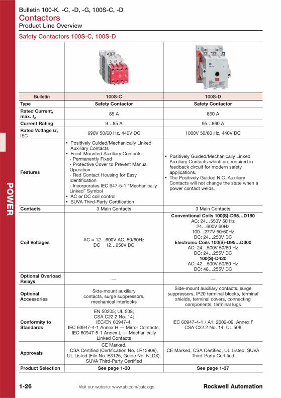
Safety Contactors 100S-C, 100S-D
Bulletin 100S-C 100S-D
Type Safety Contactor Safety Contactor
Rated Current,max. Ie
85 A 860 A
Current Rating 9…85 A 95…860 A
Rated Voltage UeIEC 690V 50/60 Hz, 440V DC 1000V 50/60 Hz, 440V DC
Features
� Positively Guided/Mechanically LinkedAuxiliary Contacts
� Front-Mounted Auxiliary Contacts:- Permanently Fixed- Protective Cover to Prevent ManualOperation- Red Contact Housing for EasyIdentification- Incorporates IEC 947-5-1 “MechanicallyLinked” Symbol
� AC or DC coil control� SUVA Third-Party Certification
� Positively Guided/Mechanically LinkedAuxiliary Contacts which are required infeedback circuit for modern safetyapplications.
� The Positively Guided N.C. AuxiliaryContacts will not change the state when apower contact welds.
Contacts 3 Main Contacts 3 Main Contacts
Coil Voltages AC = 12…600V AC, 50/60HzDC = 12…250V DC
Conventional Coils 100(S)-D95…D180AC: 24…550V 50 Hz
24…600V 60Hz100…277V 50/60HzDC: 24…250V DC
Electronic Coils 100(S)-D95…D300AC: 24…500V 50/60 Hz
DC: 24…255V DC100(S)-D420
AC: 42…500V 50/60 HzDC: 48…255V DC
Optional OverloadRelays — —
OptionalAccessories
Side-mount auxiliarycontacts, surge suppressors,
mechanical interlocks
Side-mount auxiliary contacts, surgesuppressors, IP20 terminal blocks, terminal
shields, terminal covers, connectingcomponents, terminal lugs
Conformity toStandards
EN 50205; UL 508;CSA C22.2 No. 14;IEC/EN 60947-4;
IEC 60947-4-1 Annex H — Mirror Contacts;IEC 60947-5-1 Annex L — Mechanically
Linked Contacts
IEC 60947-4-1 / A1: 2002-09, Annex FCSA C22.2 No. 14, UL 508
Approvals
CE Marked,CSA Certified (Certification No. LR13908),
UL Listed (File No. E3125, Guide No. NLDX),SUVA Third-Party Certified
CE Marked, CSA Certified, UL Listed, SUVAThird-Party Certified
Product Selection See page 1-30 See page 1-37

Bulletin 100-KContactors
1-27Visit our website: www.ab.com/catalogsRockwell Automation
PO
WE
R
⊗ Coil Voltage Codes for AC and DC Control
Mini Contactors with 3 Main Contacts
Product Selection
Mini-Contactors 100-K
Accessories for 100-K
Description For Use With Cat. No.N.O. N.C.
Front-Mounted Auxiliary ContactsAuxiliary contact blocks 2- and 4-pole versionsChoice of contact configurationsSnap on, no tools requiredElectronically-compatible bifurcatedcontacts for signals down to 15V/2mAMirror Contact performance per IEC60947-4-1
0 2
100-K05…K12⊗10
� 100-KFC02
1 1 � 100-KFC11
2 0 � 100-KFC20
0 4
100-K05…K12⊗10
� 100-KFC04
1 3 � 100-KFC13
3 1 � 100-KFC31
2 2 � 100-KFC22
4 0 � 100-KFC40
� May be ordered in package quantities of 10. Add letter M to the end of the cat. no. Example: 100-KFC02M.
Rated Operational CurrentIe [A]
Ratings for switchingAC motors — AC-2, AC-3 Auxiliary Contacts
Cat. No.
AC-3 (60°C) AC-1(40°C)
3Ø kW (50 Hz)
400V 525V 400V 525V N.O. N.C.
5 3.9 20 2.2 2.21 0 � 100-K05⊗⊗10
0 1 � 100-K05⊗01
9 6.3 20 4 41 0 � 100-K09⊗10
0 1 � 100-K09⊗01
12 9 20 5.5 5.51 0 � 100-K12⊗10
0 1 � 100-K12⊗01
� May be ordered in package quantities of 20. Add letter M to the end of the cat. no. Example: 100-K05KF10M.⊗ The Cat. No. as listed is incomplete. Select a standard Coil Voltage Code from the table below to complete theCat. No. Example: 230V, 50/60 Hz: Cat. No. 100-K05⊗10 becomes Cat. No. 100-K05KF10.
AC Control DC ControlCode Description Code Description
KJ 24V 50/60 Hz ZJ 24V DCKY 48V 50/60 Hz DJ 24V DC with integrated diodeD 110V 50 Hz ZD 110V DC
KF 230V 50/60 Hz ZA 220V DCKN 400V 50/60 HzVC 525V 50 Hz / 600V 60 Hz
For other voltages visit our website or consult your local sales office.
� Compact size, same dimensions for AC and DC� 690V rated� IP2X Finger Protection� Optional integrated surge suppressor� Compatible with 193-K bimetallic overload relay

Bulletin 100-KContactors
1-28 Visit our website: www.ab.com/catalogs Rockwell Automation
PO
WE
R
Accessories
Accessories for 100-K
Description For Use With PQ Cat. No.
Surge SuppressorPlug-in TypeLimits surge voltage on coil drop-off
RC Suppressor
24…48V AC 100/104-K,700-K � 100-KFSC50
110…280V AC 100/104-K,700-K � 100-KFSC280
380…480V AC 100/104-K,700-K � 100-KFSC480
MOV Suppressor
12…55V AC,12…77V DC
100/104-K,700-K � 100-KFSV55
56…136V AC,78…180V DC
100/104-K,700-K � 100-KFSV136
137…277V AC,181…250V DC
100/104-K,700-K � 100-KFSV277
Diode Suppressor
12…250V DC 100/104-K,700-K � 100-KFSD250
Mechanical InterlockFor interlocking of two adjacent contactorsNo added width to contactor assemblyFront mount Plug-In typeOptional auxiliary contact blocks and suppressormodules mount onto the interlock
100-K, 700-K(AC & DCControl)
100-KMCH
ECO Connecting Module — 12and 25 AFor DOL and reversing startersEco-starters mount on single DINRail (140M on DIN Rail)Electrical and mechanicalinterconnection of 140M MPCBand 100-K contactors
Connects:140M-C circuit
breakers with 100-Kcontactors
140M-C to100-K 1� 140M-C-PEK12
Power Wiring KitFor Reversing and Star/Deltacombinations.Star-point bridge not included.Min. interruption time 50 ms
— 100-K 1 100-KPR
Feeder Terminal for CompactBus BarsMax. current 34 A
Supply of compactbus bars 100-K 1 100-KWT
Three-Phase Compact Bus BarsMax. current 34 A
For 100-K, 5…12 Acontactors
45 mm spacing(3 connections)
100-K
1 100-KW453
For 100-K, 5…12 Acontactors
45 mm spacing(4 connections)
1 100-KW454
� May be ordered in package quantities of 10. Add letter M to the end of the cat. no. Example: 100-KFSC50M.PQ = Package Quantity

Bulletin 100-CContactors
1-29Visit our website: www.ab.com/catalogsRockwell Automation
PO
WE
R
⊗ Coil Voltage Codes for AC and DC Control
Contactors with 3 Main Contacts
Contactors 100-C
� Compact Sizes from 4…45 kW (9…85 A)� AC and DC Coil Control� Common Accessories for All Contactor Sizes� Front and Side Mounting of Auxiliary Contacts� Electronic and Pneumatic Timing Modules� Space-Saving Coil-Mounted Control Modules� Reversible Coil Terminations (Line or Load Side)� All Devices Can Be Attached to 35 mm DIN Mounting Rail� Environmentally Friendly Materials
Product Selection
Rated Operational CurrentIe [A]
Ratings for switchingAC Motors — (AC-2, AC-3, AC-4)
AuxiliaryContacts
Cat. No.
AC-3 (60°C) AC-1(40°C)
3Ø (50 Hz) [kW]
400V 525V 400V/415V 525V N.O. N.C.
9 7 32 4 41 0 � 100-C09⊗⊗10
0 1 � 100-C09⊗01
12 10 32 5.5 5.51 0 � 100-C12⊗10
0 1 � 100-C12⊗01
16 14 32 7.5 7.51 0 � 100-C16⊗10
0 1 � 100-C16⊗01
23 20 32 11 131 0 � 100-C23⊗10
0 1 � 100-C23⊗01
30 25 65 15 15 0 0 � 100-C30⊗00
37 30 65 18.5/20 20 0 0 � 100-C37⊗00
43 38 85 22 25 0 0 100-C43⊗00
60 55 100 32 37 0 0 100-C60⊗00
72 67 100 40 45 0 0 100-C72⊗00
85 80 100 45 55 0 0 100-C85⊗00
97 75 130 55 55 0 0 100-C97⊗00
� May be ordered in package quantities of 20. Add letter M to the end of the cat. no. Example: 100-C09KF10M).⊗ The cat. no. as listed is incomplete. Select a coil voltage code from the table below.
AC Control for 100-C DC Control for 100-C09…-C43 DC Control for 100-C60…-C85Code Description Code Description Code Description
KJ 24V 50/60 Hz ZJ 24V DCKY 48V 50/60 Hz DJ 24V DC with integrated diode DJ 24V DC with integrated diodeKD 110V 50/60 Hz EJ NEW — 24V DC electronic coilKF 230V 50/60 Hz ZD 110V DC DD 110V DC with integrated diodeKN 400V 50/60 Hz ZA 220V DC DA 220V DC with integrated diodeC 550V 50 Hz
For other voltages visit our website or consult your local sales office.

Bulletin 100S-CContactors
1-30 Visit our website: www.ab.com/catalogs Rockwell Automation
PO
WE
R
Safety Contactors 100S-C
Product Selection
� AC / DC control� 3 / 4 main contacts� Positively guided contacts according to IEC 947-5-1� Mechanically coupled Contactor and Auxiliary contact block� Protection against unintended actuation� Auxiliary contacts are electronically compatible according
to DIN 19240
Rated OperationalCurrent
Ie [A]
Ratings forSwitching AC
Motors — AC-2,AC-3, AC-4
Contact Configuration
StandardAuxiliaryContact
BifurcatedAuxiliaryContact
Main PolesAuxillaryContacts
AC-3 (60°C) AC-1(40°C)
3Ø kW (50 Hz) ♣
400V 525V 400V/415V 525V N.O. N.C. N.O. N.C. Cat. No. § Cat. No. §
Safety Contactors with 3 Main Contacts
9 7 32 4 43 0 1 4 100S-C09⊗14C 100S-C09⊗14BC
3 0 2 3 100S-C09⊗23C 100S-C09⊗23BC
12 10 32 5.5 5.53 0 1 4 100S-C12⊗14C 100S-C12⊗14BC
3 0 2 3 100S-C12⊗23C 100S-C12⊗23BC
16 14 32 7.5 7.53 0 1 4 100S-C16⊗14C 100S-C16⊗14BC
3 0 2 3 100S-C16⊗23C 100S-C16⊗23BC
23 20 32 11 13 3 0 2 3 100S-C23⊗23C 100S-C23⊗23BC
30 25 65 15 15 3 0 2 2 100S-C30⊗22C 100S-C30⊗22BC
37 30 65 18.5/20 20 3 0 2 2 100S-C37⊗22C 100S-C37⊗22BC
43 38 85 22 25 3 0 2 2 100S-C43⊗22C 100S-C43⊗22BC
60 55 100 32 37 3 0 2 2 ‡ 100S-C60⊗22C 100S-C60⊗22BC
72 67 100 40 45 3 0 2 2 ‡ 100S-C72⊗22C 100S-C72⊗22BC
85 80 100 45 55 3 0 2 2 ‡ 100S-C85⊗22C 100S-C85⊗22BC
97 75 130 55 55 3 0 2 2 ‡ 100S-C97⊗22C 100S-C97⊗22BC
Safety Contactors with 4 Main Contacts
23 20 32 11 13
4 0 0 4 100S-C23⊗404C 100S-C23⊗404BC
3 1 0 4 100S-C23⊗304C 100S-C23⊗304BC
4 0 2 2 100S-C23⊗422C 100S-C23⊗422BC
‡ Bifurcated front-mount auxiliary contacts on 100S-C60…C85 conform to mirror contact performance only.§ For other contact configurations, please consult your local sales office.♣ Three-phase ratings only apply to contactors with at least three N.O. power poles.⊗ The cat. no. as listed is incomplete. Select a coil voltage code from the table on page 1-29.

Bulletin 100-CContactors
1-31Visit our website: www.ab.com/catalogsRockwell Automation
PO
WE
R
Accessories
Auxiliary Contacts (For 100-C09…C85 contactors) �
Description For Use With
StandardAuxiliaryContact
BifurcatedAuxiliaryContact
N.O. N.C. Cat. No. � Cat. No. �
Auxiliary Contact Blocks forFront Mounting2- and 4-poleQuick and easy mountingwithout toolsElectronically-compatiblecontacts down to 17V, 5 mAMechanically linkedperformance between N.O. andN.C. poles and to the maincontactor poles (except for Ltypes)Models with equal functionwith several terminalnumbering choices1L = Late break N.C./earlymake N.O.Bifurcated versions forswitching low energy circuitsare also available ‡
0 2100-C all 100-FA02 100-FAB02
C30⊗00…C85⊗00 100-FB02 100-FBB02
1 1
100-C all 100-FA11 100-FAB11
C30⊗00…C85⊗00 100-FB11 100-FBB11
C09⊗10…C23⊗10 100-FC11 100-FCB11
2 0100-C all 100-FA20 100-FAB20
C30⊗00…C85⊗00 100-FB20 100-FBB20
1L 1LC30⊗00…C85⊗00 100-FAL11 —
C30⊗00…C85⊗00 100-FBL11 —
0 4 100-C all 100-FA04 100-FAB04
1 3 100-C all 100-FA13 100-FAB13
2 2
100-C all 100-FA22 100-FAB22
C30⊗00…C85⊗00 100-FB22 100-FBB22
C09⊗10…C23⊗10 100-FC22 100-FCB22
3 1100-C all 100-FA31 100-FAB31
C09⊗10…C23⊗10 100-FC31 100-FCB31
4 0 100-C all 100-FA40 100-FAB40
1+1L 1+1L 100-C all 100-FAL22 —
Auxiliary Contact Blocks forSide Mounting withSequence TerminalDesignations� 1- and 2-pole� Two-way numbering for right
or left mounting on thecontactor
� Quick and easy mountingwithout tools
� Electronic-compatiblecontacts down to 17V, 10mA
� Mirror contact performanceto the main contactor poles
� 1L = Late break N.C./earlymake N.O.
0 1 100-C � 100-SB01 —
1 0 100-C ‡ � 100-SB10 —
0 2 100-C ‡ � 100-SB02 —
1 1 100-C ‡ � 100-SB11 —
2 0 100-C ‡ � 100-SB20 —
1L 1L 100-C ‡ � 100-SBL11 —
� Max. number of auxiliary contacts that may be mounted:AC coil contactors — max. 4 N.O. contacts on the front of the contactor, 2 N.O. contacts on the side, 4 N.C. front or side, 6 total.DC coil contactors — max. 4 N.O. contacts on the front of the contactor or max 2 N.O. contacts on the side, 4 N.C. front or side, 4 total.
�May be ordered in package quantities of 10. Add letter M to the end of the cat. no. Example: 100-SB01M).‡ Double numbering — Left-side mounting only is recommended for cat. no. 100-C09…100-C23 due to double
numbering.

Bulletin 100-CContactors
1-32 Visit our website: www.ab.com/catalogs Rockwell Automation
PO
WE
R
Control Modules (For 100-C09…C85 contactors)
Accessories
Description For Use With Cat. No.
Pneumatic Timing ModulesPneumatic timing element contactsswitch after the delay time. Thecontacts on the main control relaycontinue to operate without delay.
On-Delay0.3…30 s Range
100-C withAC coils,
700-CF all100-FPTA30
1.8…180 s Range 100-FPTA180
Off-Delay0.3…30 s Range 100-C all,
700-CF all100-FPTB30
1.8…180 s Range 100-FPTB180
Electronic Timing Modules — On-DelayDelay of the contactor or control relaysolenoid. The contactor or control relay isenergized at the end of the delay time.
On-Delay0.1…3 s Range 100-C (all),
700-CF with110…240V, 50/60 Hz or110…250V
DC
100-ETA3
1…30 s Range 100-ETA30
10…180 s Range 100-ETA180
110…240V, 50/60 Hz110…250V DC
On-Delay
100-C with24…48V DCcoils, 700-CFwith DC coils
0.1…3 s Range 100-ETAZJ3
1…30 s Range 100-ETAZJ30
10…180 s Range 100-ETAZJ180
24…48V DC
Electronic Timing Modules — Off-DelayDelay of the contactor or control relaysolenoid. After interruption of the control signal,the contactor or control relay is de-energized at the end of the delay time.
Off-Delay
100-C, 700-CF with
110…240V50/60 Hz
coils
0.3…3 s Range 100-ETB3
1…30 s Range 100-ETB30
10…180 s Range 100-ETB180
110…240V,50/60 Hz
Off-Delay100-
C09…C37,700-CF with
24V 50/60 Hzcoils
0.3…3 s Range 100-ETBKJ3
1…30 s Range 100-ETBKJ30
10…180 s Range 100-ETBKJ180
24V, 50/60 Hz
Electronic Timing ModulesDelay of the contactor solenoid.Contactor K 3 (Y) is de-energized (off)and K 2 (D) is energized (on) after theend of the set Y end time. (Switchingdelay at 50 ms.)Continuous adjustment rangeHigh repeat accuracy
Transition Time YContactor
1…30 s Range
110…240V, 50/60 Hz
100-C with110…240V
AC, 50/60 Hzcoils
100-ETY30
Electronic Star-Delta Timing RelayOutput Y picks up when the supplyvoltage is applied and resets againafter time t. After a fixed changeovertime tu, output relay Δ picks up andremains energized until the supplyvoltage is interrupted.
� 22.5 mm width24…48V DC,
24…240V AC, 50/60 Hz100-K, 100-
C,100-D
700-FSY2DU23
� 22.5 mm width346…440V AC, 50/60 Hz
700-FSY2DA40
� 17.5 mm width24…48V DC
24…240V AC. 50/60 Hz
100-K, 100-C,
100-D700-FEY2QU23

Bulletin 100-CContactors
1-33Visit our website: www.ab.com/catalogsRockwell Automation
PO
WE
R
Accessories
Control Modules (For 100-C09…C85 contactors), continued
⊗ Voltage Suffix Code for Mechanical LatchThe cat. no. as listed is incomplete. Select a voltage suffix code from the table below to completethe cat. no. Example: 230V, 50/60 Hz: Cat. no. 100-FL11⊗ becomes cat. no. 100-FL11KF.
AC Control AC Control AC ControlCode Description Code Description Code Description
KJ 24V 50/60 Hz KD 110V 50/60 Hz KN 400V 50/60 HzKY 48V 50/60 Hz KF 230V 50/60 Hz
For other AC voltages visit our website or consult your local sales office.
Description Voltage Range For Use With Cat. No.
Mechanical InterlocksFor interlocking of two contactors.Common interlock for all Bul. 100-Ccontactor sizesInterlocking of different sizespossibleMechanical and electricalinterlocking possible in one moduleby means of integrated auxiliarycontacts9 mm dovetail connector included
Mechanical onlywithout auxiliary contacts
100-C (except100-C40, -
C90)
100-MCA00
Mechanical/ electricalwith 2 N.C. auxiliary
contacts100-MCA02
Mechanical LatchFollowing contactor latching, thecontactor coil is immediately de-energized (off) by the N.C. auxiliarycontact (65-66).Electrical or manual release1 N.O. + 1 N.C. auxiliary contactsSuitable for all Bul. 100-C contactorsizes, 9…85 A
Maximum commandduration 0.03…10 s
100-C with ACcoils (except
100-C90)100-FL11⊗
DC Interface (Electronic)Interface between the DC controlsignal (PLC) and the AC operatingmechanism of the contactor.Requires no additional surgesuppression on the relay coils
Input: 12V DCOutput: 110…240V AC
100-C with ACcoils
110…240V AC
100-JE12
Input: 18…30V DCOutput: 110…240V AC 100-JE
Input: 48V DCOutput: 110…240V AC 100-JE48
Surge SuppressorsFor limitation of coilswitching transients.Plug-in, coil mounted.Suitable for all 100-Ccontactor sizes, 5 A.RC, varistor, anddiode versions.
RC ModuleAC
operatingmechanism
24…48V AC, 50/60 Hz100-C with AC
coils
� 100-FSC48
110…280V AC, 50/60 Hz � 100-FSC280
380…480V AC, 50/60 Hz � 100-FSC480
VaristorModuleAC/DC
operatingmechanism
12…55V AC/ 12…77VDC
100-C
� 100-FSV55
56…136V AC/ 78…180VDC � 100-FSV136
137…277V AC/181…350V DC � 100-FSV277
278…575V AC � 100-FSV575
DiodeModule
DCoperating
mechanism
12…250V DC 100-C with DCcoils � 100-FSD250
� May be ordered in package quantities of 10. Add letter M to the end of the cat. no. Example: 100-FSC48M.

Bulletin 100-CContactors
1-34 Visit our website: www.ab.com/catalogs Rockwell Automation
PO
WE
R
Marking Systems
Reversing Starter Kits
Star-Delta Starter Kits
170-PW23
Accessories
Power wiring kits were designed to aid in the field assembly ofopen-transition star-delta and reversing starters that use Bulletin100-C contactors. These kits include line, load (and start-point)connections.
3-Phase Rating (50 Hz) Use with Cat. No. 100-...
Cat. No.
230V 380/415V 500V 690V Delta Star
[kW] 1M 2M 1S
5.5 8 8 8 C09 C09 C09
170-PW237.5 11 11 11 C12 C12 C09
10 14 15 14 C16 C16 C12
14 21 21 19 C23 C23 C12
18 28 28 28 C30 C30 C16170-PW37
19 35 35 32 C37 C37 C23
23 40 40 41 C43 C43 C30 170-PW43
33 58 60 56 C60 C60 C37170-PW72
39 69 67 70 C72 C72 C43
47 82 82 81 C85 C85 C60 170-PW85
Description PQ Cat. No.
Label Sheet105 self-adhesive paper labels each, 6 x 17 mm 10 100-FMS
Marking Tag Sheet160 perforated paper labels each, 6 x 17 mm, to be used with atransparent cover
10 100-FMP
Transparent CoverTo be used with marking tag sheets 100 100-FMC
PQ = Package Quantity
Description For Use With Cat. No.
Reversing Power Wiring KitsFor reversing connection with a solid-state orthermal overload relay
100-C09…C23 105-PW23
100-C30…C37 105-PW37
100-C43 105-PW43
100-C60…85 105-PW85

Bulletin 100-CContactors
1-35Visit our website: www.ab.com/catalogsRockwell Automation
PO
WE
R
Enclosures
Accessories
DeviceNet Starter Auxiliary DSA I/0 for Distributed Starters
No. of Inputs No. of Outputs Cat. No.
4 (120V AC) 2 Relay (250V rated) 100-DNY41R
4 (24V DC) 2 Relay (250V rated) 100-DNY42R
4 (24V DC) 2 Solid-State (24V DC) 100-DNY42S
� Includes complete connector plug set� Removable connectors� Slender 22.5 mm wide profile� Screw or DIN Rail mounting� Rotary node address switches� DeviceNet address settable via hardware or software — no
need to adjust rotary node address switches� DeviceLogix functionality
Inputs from: Outputs to:� Contactor Aux � Contactor Coil� Relay � Starter� Pushbutton � Relay� Proximity Switch � Signal Lamp� Limit Switch � Valve
Description For Use With Cat. No.
Plastic Enclosures for DOL StartersFor Bulletin 100-C09…C23 contactors with overloadrelays Bulletin 193-ED, -EE, or -T1Protection class IP66Prestampings for two pilot lights
Material: ABS V-0
With blue RESET push button 100-C09…C23 +193-ED, -EE,
-CT
198E-A0S1
With green START and raised redSTOP/RESET push buttons, STARTcontact kit included.
198E-A0S4
Material: PC V-0
With blue RESET push button 100-C09…C23 +193-ED, -EE,
-CT
198E-C0S1
With green START and raised redSTOP/RESET push buttons, STARTcontact kit included.
198E-C0S4
Pushbutton LatchFor maintained contact control, enclosures withSTART/STOP push buttons.
198E-A0S4,198E-C0S4 198E-PLA
Neutral Terminal 198E-A…,198E-C… 198E-PNT
START Contact KitIncluded in the enclosure, as spare part only.
198E-A0S4,198E-C0S4 198E-PCK
Pilot Lights, see 140A page 3-7

Bulletin 100-DContactors
1-36 Visit our website: www.ab.com/catalogs Rockwell Automation
PO
WE
R
Contactors with 3 Main Contacts
Contactors 100-D
Product Selection
� Conventional and Electronic Coils� 3 Main Contacts
100-D95 100-D420 100-D860
Rated Operational CurrentIe [A]
Ratings for Switching ACMotors — AC-2, AC-3, AC-4
AuxiliaryContacts
Cat. No.
AC-3 (60 °C) AC-1(40 °C)
3Ø kW (50 Hz)
400V 525V 400V 525V N.O. N.C.
3-Pole AC-Operated Contactors
95 95 160 53 76 1 1 100-D95⊗⊗11
110 110 160 61 80 1 1 100-D110⊗11
140 115 ‡ / 140 250 78 111 ‡ / 135 1 1 100-D140⊗11
180 140 ‡ / 180 250 101 135 ‡ / 176 1 1 100-D180⊗11
210 210 350 118 205 1 1 100-D210⊗11
250 250 350 140 250 1 1 100-D250⊗11
300 300 450 170 290 1 1 100-D300⊗11
420 420 540 238 420 1 1 100-D420⊗11
630 630 800 355 500 1 1 100-D630⊗11
860 753 1000 500 500 1 1 100-D860⊗11
3-Pole DC-Operated Contactors
95 95 160 53 762 1/1L � 100-D95⊗22L
1 1 100-D95⊗11
110 110 160 61 802 1/1L � 100-D110⊗22L
1 1 100-D110⊗11
140115 ‡
250 78111 ‡ 2 1/1L � 100-D140⊗22L
140 135 1 1 100-D140⊗11
180140 ‡
250 101135 ‡ 2 1/1L � 100-D180⊗22L
180 176 1 1 100-D180⊗11
210 210 350 118 205 1 1 100-D210⊗11
250 250 350 140 250 1 1 100-D250⊗11
300 300 450 170 290 1 1 100-D300⊗11
420 420 540 238 420 1 1 100-D420⊗11
630 630 800 355 500 1 1 100-D630⊗11
860 753 1000 500 500 1 1 100-D860⊗11
�Conventional Coil: The pickup winding must be interconnected with the N.C. late-breaking auxiliary contact.‡ With conventional coil⊗ The cat. no. as listed is incomplete. Select a coil voltage code from the table on page 1-38 to complete the
cat. no. Example: 230V, 50/60 Hz: Cat. no. 100-D95⊗11 becomes cat. no. 100-D95KF11.

Bulletin 100S-DContactors
1-37Visit our website: www.ab.com/catalogsRockwell Automation
PO
WE
R
Contactors with 3 Main Contacts
Safety Contactors 100S-D
Product Selection
� Conventional and Electronic Coils� 3 Main Contacts
Rated Operational CurrentIe [A]
Ratings for SwitchingAC Motors — AC-2,
AC-3, AC-4AuxiliaryContacts
StandardAuxiliaryContact
BifurcatedAuxiliaryContactAC-3 (60 °C) AC-1
(40 °C)
3Ø kW (50 Hz)
400V 525V 400V 525V N.O. N.C. � Cat. No. Cat. No.
3-Pole AC-Operated Contactors
95 95 160 53 76 2 2 100S-D95⊗22C 100S-D95⊗22BC
110 110 160 61 80 2 2 100S-D110⊗22C 100S-D110⊗22BC
140 115 ‡ / 140 250 78 111 ‡ / 135 2 2 100S-D140⊗22C 100S-D140⊗22BC
180 140 ‡ / 180 250 101 135 ‡ / 176 2 2 100S-D180⊗22C 100S-D180⊗22BC
210 210 350 118 205 2 2 100S-D210⊗22C 100S-D210⊗22BC
250 250 350 140 250 2 2 100S-D250⊗22C 100S-D250⊗22BC
300 300 450 170 290 2 2 100S-D300⊗22C 100S-D300⊗22BC
420 420 540 238 420 2 2 100S-D420⊗22C 100S-D420⊗22BC
630 630 800 355 500 2 2 100S-D630⊗22C 100S-D630⊗22BC
860 753 1000 500 500 2 2 100S-D860⊗22C 100S-D860⊗22BC
3-Pole DC-Operated Contactors
95 95 160 53 763 2/1L � 100S-D95⊗33LC —
2 2 100S-D95⊗22C 100S-D95⊗22BC
110 110 160 61 803 2/1L � 100S-D110⊗33LC —
2 2 100S-D110⊗22C 100S-D110⊗22BC
140115 ‡
250 78111 ‡ 3 2/1L � 100S-D140⊗33LC —
140 135 2 2 100S-D140⊗22C 100S-D140⊗22BC
180140 ‡
250 101135 ‡ 3 2/1L � 100S-D180⊗33LC —
180 176 2 2 100S-D180⊗22C 100S-D180⊗22BC
210 210 350 118 205 2 2 100S-D210⊗22C 100S-D210⊗22BC
250 250 350 140 250 2 2 100S-D250⊗22C 100S-D250⊗22BC
300 300 450 170 290 2 2 100S-D300⊗22C 100S-D300⊗22BC
420 420 540 238 420 2 2 100S-D420⊗22C 100S-D420⊗22BC
630 630 800 355 500 2 2 100S-D630⊗22C 100S-D630⊗22BC
860 753 1000 500 500 2 2 100S-D860⊗22C 100S-D860⊗22BC
� The N.C. contacts meet IEC 60947-4 Annex F requirements to mirror contact performance. The N.C. mirrorcontacts are wired in series or parallel and must be used as monitoring contacts with feedback to the safetycircuit.
�Conventional Coil: The pickup winding must be interconnected with the N.C. late-breaking auxiliary contact.‡ With conventional coil⊗ The cat. no. as listed is incomplete. Select a coil voltage code from the table on page 1-38 to complete the
cat. no. Example: 230V, 50/60 Hz: Cat. no. 100-D95⊗11 becomes cat. no. 100-D95KF11.

Bulletin 100-D, 100S-DContactors
1-38 Visit our website: www.ab.com/catalogs Rockwell Automation
PO
WE
R
⊗ Coil Voltage Codes for AC Control
Conventional Coil [V] 24 48 110 120 220-230 230 240 380-400 440 550
-D95…-D18050 Hz K Y D — A — — N — C
60 Hz J X — D — — A — N —
-D95…-D110 50/60 Hz — — KN — — KF — — — —
Electronic Coil w/ EI Interface � [V] 24 42-64 110-130 208-277 380-415 440-480 380-500
-D95…-D300 50/60 Hz EJ � EY ED EA — — EN
-D420 50/60 Hz — — ED EA — — EN
-D630…-D860 50/60 Hz — — ED EA EN EB —
⊗ Coil Voltage Codes for DC Control
Conventional Coil [V] 24 48 110 220-D95…-D180 ‡ DC ZJ ZY ZD ZA
Electronic Coil w/ EI Interface � [V] 24 48-72 110-130 200-255
-D95…-D300 DC EZJ EZY EZD EZA
-D420 DC — — EZD EZA
-D630…-D860 DC — — ED EA
� Signal voltage of the electronic interface (100-D…, 100S-D…): nominal Ue: 24V DC/Ie: 15 mAPickup voltage: 13.0V DC…30.2V DC Dropout Voltage: –3.0V DC…+5.0V DC.
�Not available with 100(S)-D300‡ For conventional DC coils, the pickup winding must be interconnected with the N.C. late-breaking auxiliary
contact(s).
Accessories for 100-D, 100S-D
Product Selection / Accessories
DescriptionFor Use
With
Auxiliary Contact
Standard Bifurcated
N.O. N.C. Cat. No. Cat. No.
Auxiliary ContactsSide-mountedwith IEC sequence terminal designationsStandard contacts 17V/10 mABifurcated contacts for signals down to5V/2 mA
1 1100-D left orright insidemounting
100-DS1-11 100-DS1-B11H
1 1100-D left orright outside
mounting100-DS2-11 100-DS2-B11H
1 1L 100-D left orright insidemounting
100-DS1-L11 100-DS1-BL11H
2 0 100-DS1-20 100-DS1-B20H
2 0100-D left orright outside
mounting100-DS2-20 100-DS2-B20H
Auxiliary ContactsElectronically compatible auxiliarycontactsIdeal for use when switching low-powercontrol circuitsWith IEC sequence terminal designationsContact ratings:AC-12, 250V, 0.1 AAC-15, DC-13, 3...125V, 1...100 mA
1 1100-D left orright insidemounting
100-DS1-B11 —

Bulletin 100S-DContactors
1-39Visit our website: www.ab.com/catalogsRockwell Automation
PO
WE
R
Accessories
Accessories for 100-D, 100S-D, Continued
Description For Use With Cat. No.
Interlock — Mechanical OnlyNo additional space required 100-D95…100-D420 100-DMA00
Interlock — Dual Electrical/MechanicalNo additional space requiredTwo N.C. auxiliary contacts
100-D95…100-D860 100-DMD02
Interlock — Dual Electrical/MechanicalProvides interlocking between Bul. 100-Cand Bul. 100-D contactorsTwo N.C. auxiliary contacts
100-C60…100-C85 between100-D95…100-D180 100-DMC02
Terminal LugsSet of twoProtection class IP2X per IEC 60529 andDIN 40 050
100-D95, 100-D110 100-DTB110
100-D140, 100-D180, 100-D95E…D180E, 193-EC_F, 193-
EE_F100-DTB180
100-D210...100-D420, 193-EC_G, 193-EF2C, 193-EE_G 100-DTB420
Control Circuit Terminal2 x 2.5 mm2
Connects to Cat. Nos. 100-D95...D180 100-DAT1
Connects to Cat. Nos. 100-D210...D420 100-DAT2
Phase BarriersSet of 4
100-D630…D860, 193-EC_H,193-EE_H 100-DPB860
Description Suppressor Rating For Use With Cat. No.
Suppressor Module for Bul. 100-DContactors• For limiting surge voltage when
coil circuits are interrupted• Supplied as standard on all
conventional DC coil contactorsand all electronic coil contactors(as part of the supply module ordelivered with separate suppressormodule)
RC Module (ACcontrol)for contactors withconventional coil21...48V, 50 Hz;24...55V, 60 Hz 100-
D95...100-D180
100-DFSC48
95...110V, 50 Hz;110...127V, 60 Hz 100-DFSC110
180...277V, 50 Hz;208...277V, 60 Hz 100-DFSC240
380...550V, 50 Hz;440...600V, 60 Hz 100-DFSC550
Varistor Modulefor contactors withconventional coil55V AC
100-D95...100-
D180100-DFSV55
56...136V AC 100-DFSV136137...277V AC 100-DFSV277278...600V AC 100-DFSV575
208...277V AC �100-
D95...100-D180
100-DFSV550
� For overvoltage category IV (IEC 947 for 100-D...-EI) e.g., lightning protection requirements.

Bulletin 100S-DContactors
1-40 Visit our website: www.ab.com/catalogs Rockwell Automation
PO
WE
R
Accessories
Accessories for 100-D, 100S-D, Continued
DescriptionOutput
Connection
For Use With
Cat. No.100-D
95…180100-D
210…420100-D
630…860
Reversing: Input ConnectionWye-Delta: Main-Deltaconnection
50 mm2 X � 100-D180-VL
120 mm2 X � 100-D420-VL
350 mm2 X � 100-D860-VL
50 mm2 X � 100-D180-VLTB
120 mm2 X � 100-D420-VLTB
Reversing: OutputConnectionWye-Delta: Delta-Wyeconnection
50 mm2 X � 100-D180-VT
120 mm2 X � 100-D420-VT
350 mm2 X � 100-D860-VT
50 mm2 X � 100-D180-VTTB
120 mm2 X � 100-D420-VTTB
Delta-Wye connection if100-D95…180 is used as aWye contactor
80 mm2 ⎯ X � 100-D420-VYTB
Wye-Delta: Neutral bridge
⎯ X 100-D180-VYU
⎯ X 100-D420-VYU
⎯ X 100-D860-VYU
Power Wiring Kits (for contactors using100-DL lug kits)
For 100-D95…100-D180Reversing 100-DPW180
Two-speed, or changeover 100-D180-VL
Wye-Delta/Star-Delta 100-DPY180
For 100-D210…100-D420Reversing 100-DPW420
Two-speed, or changeover 100-D420-VL
Wye-Delta/Star-Delta 100-DPY420
For 100-D630…100-D860Reversing 100-DPW860
Two-speed, or changeover 100-D860-VL
Terminal ShieldsSet of twoProtection class IP10 per IEC 60529 andDIN 40 050For direct-on-line, reversing, two-speed,and wye-delta/star-delta assemblies
100-D95, 100-D110 100-DTS110
100-D140, 100-D180, 100-D95-E…100-D180-E 100-DTS180
100-D210...100-D420 100-DTS420
Terminal CoversProtection class IP20 per IEC 60529 andDIN 40 050For direct-on-line, reversing, two-speed,and wye-delta/star-delta assemblies
100-D95…100-D180, 193-EC_F,193-EE_F 100-DTC180
100-D210...100-D420, 193-EC_G,193-EE_G 100-DTC420
100-D630…100-D860, 193-EC_H, 193-EE_H 100-DTC860
� For use with terminal lugs 100-DL… (UL/CSA), see publication A115-CA001…� For use with terminal blocks 100-DTB…

Bulletin 100-GContactors
1-41Visit our website: www.ab.com/catalogsRockwell Automation
PO
WE
R
⊗ Coil Voltage Codes for AC and DC Control
Contactors with 3 Main Contacts
Contactors 100-G
Product Selection
� 315...710 kW, 400V� 350…900 Hp, 460/575V� 3-Pole Contactors� 4th Add-On Neutral Switching Pole� AC and DC Control� Horizontal and Vertical Interlocking� Mechanical Latching� Meets IEC, CE, UL, and cUL Standards and Approvals
[V] 100-110 110-120 200-220 220-240 345-380 380-415 440-480
100-G550...100-G86050/60 Hz — KD — KF — KN KB
DC KD — KF — KN — —
[V] 110 110-115 220 220-230 240 380-400 480
100-G1000...100-G120050/60 Hz — KD — KF KA KN KU
DC ZD — ZA — — — —
For other voltages visit our website or consult your local sales office.
Rated Operational CurrentIe [A]
Ratings for switchingAC Motors — AC-2, AC-3 Auxiliary Contacts
Cat. No.
AC-3 (60 °C) AC-1(40°C)
3Ø kW (50 Hz)
400V 525V 400V 525V N.O. N.C.
550 540 760 315 400 2 2 100-G550⊗22
700 690 1000 400 500 2 2 100-G700⊗22
860 840 1100 500 630 2 2 100-G860⊗22
1000 980 1200 560 750 2� 2 � 100-G1000⊗12
1200 1170 1350 710 900 2� 2 100-G1200⊗12
� 1 N.O. contact used in control circuit�No UL/cUL

Bulletin 100-GContactors
1-42 Visit our website: www.ab.com/catalogs Rockwell Automation
PO
WE
R
⊗ Coil Voltage Codes for AC Control
Accessories
[V] 110…120 220…240 380…415 440…480100-G550... 100-G860 50/60Hz KD KF KN KB
For other voltages visit our website or consult your local sales office.
Description For Use With Cat. No.
Auxiliary Contact BlockFor mounting between T1 & T2 or between T2 &T3Adjustable; provides normal, delayed, oroverlapping contactsMax. two blocks/contactorAlternate terminal marking tags included2 N.O. and 2 N.C. contacts
100-G550…100-G860 100-EF22
Auxiliary Contact BlockFor side mounting on either side of the contactorMax. four blocks/contactorAlternate terminal marking tags included1 N.O. and 1 N.C. contact
100-G1000…100-G1200 100-EB11
1 N.C. and 1 N.O. late break 100-G1000, 100-G1200 100-EB11DC
Fourth Add-On Neutral Switching PoleLeft- or right-side mountableNote: no UL/cUL
100-G550 100-NP500-5
100-G700, 100-G860 100-NP500-6
100-G700, 100-G860 100-NP1000-6
100-G1000, 100-G1200 100-NP1000-7
Mechanical LatchMechanical life: 0.5 million operationsDirect and Impulse Control
100-G550 100-FLAM5⊗
100-G700, 100-G860 100-FLAM6⊗
Mechanical Interlock — Horizontal
100-G550 to 100-G550 100-MC00-5H
100-G550 to 100-G700or 100-G860 100-MC00-56H
100-G700 or 100-G860to 100-G700 or 100-
G860100-MC00-6H
100-G700 or 100-G860to 100-G1000 or 100-
G1200100-MC00-67H
100-G1000 or 100-G1200 to 100-G1000 or
100-G1200100-MC00-7H
Mechanical Interlock — Vertical
100-G550 to 100-G550 100-MC00-5V
100-G550 to 100-G700or 100-G860 100-MC00-56V
100-G700 or 100-G860to 100-G700 or 100-
G860100-MC00-6V
100-G700 or 100-G860to 100-G1000 or 100-
G1200100-MC00-67V
100-G1000 or 100-G1200 to 100-G1000 or
100-G1200100-MC00-7V
Accessories for 100-G

Bulletin 156-BSolid State Contactors
1-43Visit our website: www.ab.com/catalogsRockwell Automation
PO
WE
R
Product Selection
The Bulletin 156 Solid-State Contactors are ideal replacements for electro-mechanical contactorswhere fast and demanding switching of loads such as heaters, solenoids, transformers, and motors,is required.
� Compact modular design complete with heatsink� DIN Rail mountable� Simple installation� Available in single-phase, dual-phase, or three-phase version� Operational current rating 20…90 A� LED status indication� AC, DC, and analog control options� Zero-cross switching
Solid-State Power ContactorsSingle-Phase
Solid-State Contactors
Dual-Phase
Current Rating
Control Voltage
Housing Size
Operational Voltage
@ 25 °C @ 40 °C 24…230V AC 42…600V AC
[A] [A] [mm] Cat. No. Cat. No.
20 1724…275V AC, 24…48V DC
22.5
156-B20AA1 156-B20CA1
5…24V DC 156-B20AB1 156-B20CB1
30 2524…275V AC, 24…48V DC 156-B30AA1 156-B30CA1
5…24V DC 156-B30AB1 156-B30CB1
45 3824…275V AC, 24…48V DC
45
156-B45AA1 156-B45CA1
5…24V DC 156-B45AB1 156-B45CB1
50 4324…275V AC, 24…48V DC 156-B50AA1 156-B50CA1
5…24V DC 156-B50AB1 156-B50CB1
70 6024…275V AC, 24…48V DC
90 156-B70AA1 156-B70CA1
5…24V DC 156-B70AB1 156-B70CB1
75 6424…275V AC, 24…48V DC
45 �156-B75AA1 156-B75CA1
5…24V DC 156-B75AB1 156-B75CB1
90 7724…275V AC, 24…48V DC
90 �156-B90AA1 156-B90CA1
5…24V DC 156-B90AB1 156-B90CB1
� With fan. External fan supply 24V DC required.
Current Rating
Control Voltage
Housing Size
Operational Voltage
@ 25 °C @ 40 °C 24…230V AC 48…600V AC
[A] [A] [mm] Cat. No. Cat. No.
25 2024…275V AC, 24…48V DC
45156-B25AA2 156-B25CA2
5…24V DC 156-B25AB2 156-B25CB2
32 2524…275V AC, 24…48V DC
90156-B32AA2 156-B32CA2
5…24V DC 156-B32AB2 156-B32CB2

Bulletin 156-BSolid State Contactors
1-44 Visit our website: www.ab.com/catalogs Rockwell Automation
PO
WE
R
Three-Phase
Product Selection
Current Rating
Control Voltage
Housing Size
Operational Voltage
@ 25 °C @ 40 °C 24…230V AC 48…600V AC
[A] [A] [mm] Cat. No. Cat. No.
20 1624…275V AC, 24…190V DC
45156-B20AA3 156-B20CA3
5…24V DC 156-B20AB3 156-B20CB3
25 2024…275V AC, 24…190V DC
90 156-B25AA3 156-B25CA3
5…24V DC 156-B25AB3 156-B25CB3
32 2624…275V AC, 24…190V DC
45 �156-B32AA3 156-B32CA3
5…24V DC 156-B32AB3 156-B32CB3
� With fan. External fan supply 24V DC required.
Solid-State Specialty ContactorsSingle-Phase with Current Monitoring
Current Rating
SupplyVoltage
ControlVoltage
HousingSize
Alarm Type
Operational Voltage
@ 25 °C @ 40 °C 24…265V AC 42…660V AC
[A] [A] [mm] Cat. No. Cat. No.
30 27
24V DC 4…32V DC
45PNP, N.O. 156-B30ABP 156-B30CBP
NPN, N.O. 156-B30ABN 156-B30CBN
50 36 45PNP, N.O. 156-B50ABP 156-B50CBP
NPN, N.O. 156-B50ABN 156-B50CBN
Single-Phase, Single-Pole, Multi-function Analog
Current Rating
Control Input
Housing Size
Operational Voltage
@ 25 °C @ 40 °C 90…265V AC 200…550V AC 410…660V AC
[A] [A] [mm] Cat. No. Cat. No. Cat. No.
30 230…10V DC‡
45156-B30AV1 156-B30BV1 156-B30CV1
4…20 mA 156-B30AC1 156-B30BC1 156-B30CC1
50 400…10V DC‡
45156-B50AV1 156-B50BV1 156-B50CV1
4…20 mA 156-B50AC1 156-B50BC1 156-B50CC1
‡ Requires a 24V AC/DC supply to power the control circuitry of the solid-state contactor.

Bulletin 190SStarters
1-45Visit our website: www.ab.com/catalogsRockwell Automation
PO
WE
R
Starter Selection
Product Line Overview
Bulletin 190S / 191S� 190E� / 191E� 103T� / 107T�
Type Compact Starters Eco Starters 3-Component Starters
Current Range 0.1…45 A 0.1…25 A 0.1…100 A
Motor Range (Max. Kilowatt) 22 kW at 400V 11 kW at 400V 45 kW at 400V
Short Circuit Motor Protection � � �
Overload Protection: Trip Class 10, 15, 20, 30 10 10, 15, 20, 30
Mounting Options
Standard Busbar Mount — — �
Iso Busbar Mount — — �
Panel Mount � � �
Standards Compliance
UL 508 and CSA 22.2, No. 14,Self-Protected CombinationMotor Controller
� � �
IEC 60947-4, CE � � �
Major Components
140M Motor Protection CircuitBreaker � � �
100C Contactors � � �
193-E Overload Relays — — �
Accessories
Lockable Knobs � � �
Aux/Trip Contacts for CircuitBreaker � � �
Aux Contacts for Contactor � � �
UV/Shunt Trip for Circuit Breaker � � �
Product Selection See page 1-46 � For detailed information visit our website orconsult your local sales office.
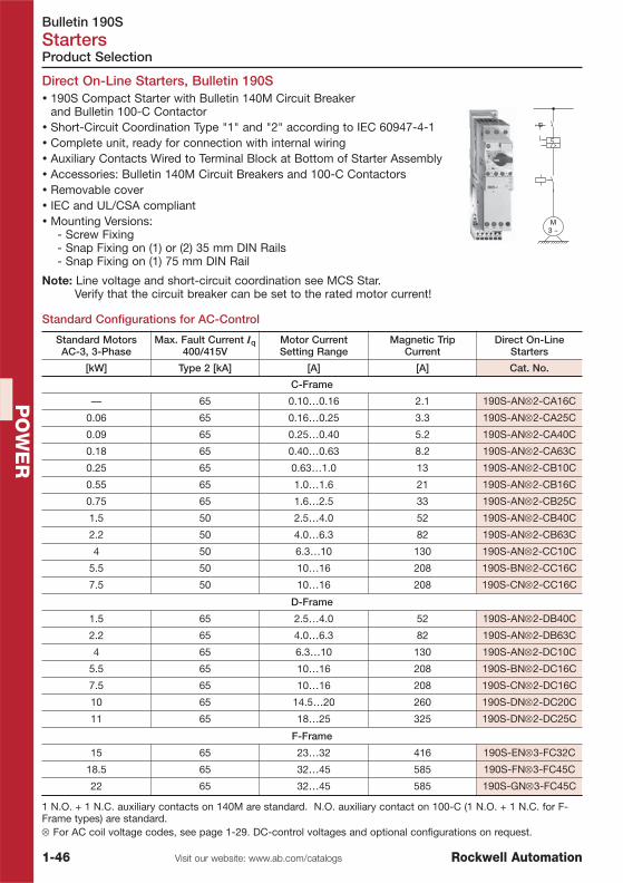
Bulletin 190SStarters
1-46 Visit our website: www.ab.com/catalogs Rockwell Automation
PO
WE
R
Product Selection
Standard Configurations for AC-Control
Direct On-Line Starters, Bulletin 190S
M3 ~
I >
� 190S Compact Starter with Bulletin 140M Circuit Breakerand Bulletin 100-C Contactor
� Short-Circuit Coordination Type "1" and "2" according to IEC 60947-4-1� Complete unit, ready for connection with internal wiring� Auxiliary Contacts Wired to Terminal Block at Bottom of Starter Assembly� Accessories: Bulletin 140M Circuit Breakers and 100-C Contactors� Removable cover� IEC and UL/CSA compliant� Mounting Versions:
- Screw Fixing- Snap Fixing on (1) or (2) 35 mm DIN Rails- Snap Fixing on (1) 75 mm DIN Rail
Note: Line voltage and short-circuit coordination see MCS Star. Verify that the circuit breaker can be set to the rated motor current!
Standard MotorsAC-3, 3-Phase
Max. Fault Current Iq400/415V
Motor CurrentSetting Range
Magnetic TripCurrent
Direct On-LineStarters
[kW] Type 2 [kA] [A] [A] Cat. No.
C-Frame
— 65 0.10…0.16 2.1 190S-AN⊗2-CA16C
0.06 65 0.16…0.25 3.3 190S-AN⊗2-CA25C
0.09 65 0.25…0.40 5.2 190S-AN⊗2-CA40C
0.18 65 0.40…0.63 8.2 190S-AN⊗2-CA63C
0.25 65 0.63…1.0 13 190S-AN⊗2-CB10C
0.55 65 1.0…1.6 21 190S-AN⊗2-CB16C
0.75 65 1.6…2.5 33 190S-AN⊗2-CB25C
1.5 50 2.5…4.0 52 190S-AN⊗2-CB40C
2.2 50 4.0…6.3 82 190S-AN⊗2-CB63C
4 50 6.3…10 130 190S-AN⊗2-CC10C
5.5 50 10…16 208 190S-BN⊗2-CC16C
7.5 50 10…16 208 190S-CN⊗2-CC16C
D-Frame
1.5 65 2.5…4.0 52 190S-AN⊗2-DB40C
2.2 65 4.0…6.3 82 190S-AN⊗2-DB63C
4 65 6.3…10 130 190S-AN⊗2-DC10C
5.5 65 10…16 208 190S-BN⊗2-DC16C
7.5 65 10…16 208 190S-CN⊗2-DC16C
10 65 14.5…20 260 190S-DN⊗2-DC20C
11 65 18…25 325 190S-DN⊗2-DC25C
F-Frame
15 65 23…32 416 190S-EN⊗3-FC32C
18.5 65 32…45 585 190S-FN⊗3-FC45C
22 65 32…45 585 190S-GN⊗3-FC45C
1 N.O. + 1 N.C. auxiliary contacts on 140M are standard. N.O. auxiliary contact on 100-C (1 N.O. + 1 N.C. for F-Frame types) are standard.⊗ For AC coil voltage codes, see page 1-29. DC-control voltages and optional configurations on request.

Bulletin 140M-RC, 100-CRStarter Components with Spring Clamp Terminals
1-47Visit our website: www.ab.com/catalogsRockwell Automation
PO
WE
R
Starter Components
Product Line Overview
Bulletin 140M-RC 100-CR
Spring Clamp Terminals � �
Max. Current Ie 16 A 16 A
Current Rating 0.1…16 A 9…16 A
Short Circuit Protection � —
Standard Magnetic Trip � —
Overload Protection � —
Trip Class 10 —
Standards Compliance:
CSA 22.2, No. 14 � �
UL 508 Manual, Self Protected (Type E) � �
UL 508 (Group Install.) � �
UL 508 (Overload Protection) � �
IEC 60947-2 � �
IEC 60947-4 � �
CE � �
Accessories
Ext. Rotary Operator � —
Auxiliary Contacts � �
Trip Indication Contacts � —
Product Selection See page 1-48 See page 1-49
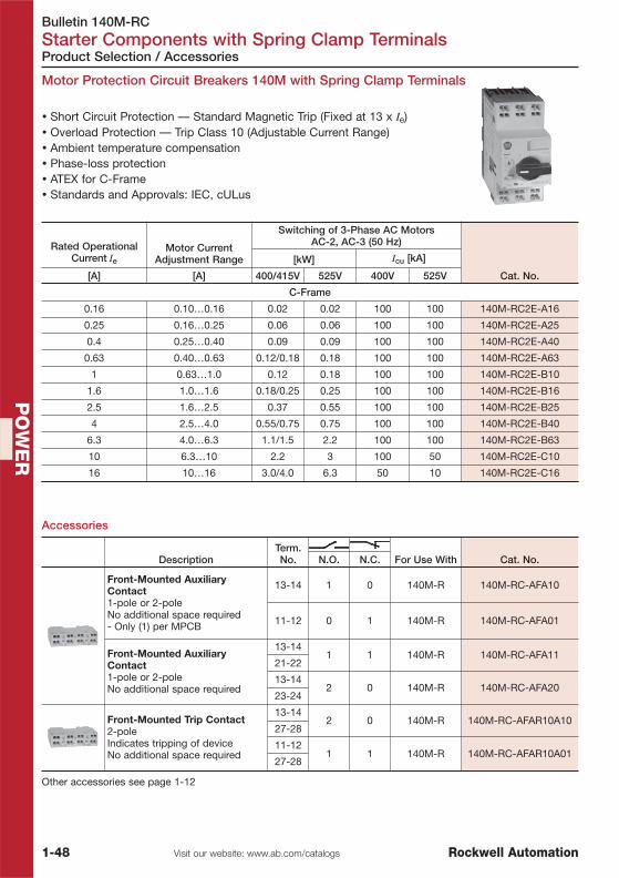
Bulletin 140M-RCStarter Components with Spring Clamp Terminals
1-48 Visit our website: www.ab.com/catalogs Rockwell Automation
PO
WE
R
Accessories
Motor Protection Circuit Breakers 140M with Spring Clamp Terminals
Product Selection / Accessories
� Short Circuit Protection — Standard Magnetic Trip (Fixed at 13 x Ie)� Overload Protection — Trip Class 10 (Adjustable Current Range)� Ambient temperature compensation� Phase-loss protection� ATEX for C-Frame� Standards and Approvals: IEC, cULus
DescriptionTerm.No. For Use With Cat. No.N.O. N.C.
Front-Mounted AuxiliaryContact1-pole or 2-poleNo additional space required- Only (1) per MPCB
13-14 1 0 140M-R 140M-RC-AFA10
11-12 0 1 140M-R 140M-RC-AFA01
Front-Mounted AuxiliaryContact1-pole or 2-poleNo additional space required
13-141 1 140M-R 140M-RC-AFA11
21-22
13-142 0 140M-R 140M-RC-AFA20
23-24
Front-Mounted Trip Contact2-poleIndicates tripping of deviceNo additional space required
13-142 0 140M-R 140M-RC-AFAR10A10
27-28
11-121 1 140M-R 140M-RC-AFAR10A01
27-28
Other accessories see page 1-12
Rated OperationalCurrent Ie
Motor CurrentAdjustment Range
Switching of 3-Phase AC MotorsAC-2, AC-3 (50 Hz)
Cat. No.
[kW] Icu [kA]
[A] [A] 400/415V 525V 400V 525V
C-Frame
0.16 0.10…0.16 0.02 0.02 100 100 140M-RC2E-A16
0.25 0.16…0.25 0.06 0.06 100 100 140M-RC2E-A25
0.4 0.25…0.40 0.09 0.09 100 100 140M-RC2E-A40
0.63 0.40…0.63 0.12/0.18 0.18 100 100 140M-RC2E-A63
1 0.63…1.0 0.12 0.18 100 100 140M-RC2E-B10
1.6 1.0…1.6 0.18/0.25 0.25 100 100 140M-RC2E-B16
2.5 1.6…2.5 0.37 0.55 100 100 140M-RC2E-B25
4 2.5…4.0 0.55/0.75 0.75 100 100 140M-RC2E-B40
6.3 4.0…6.3 1.1/1.5 2.2 100 100 140M-RC2E-B63
10 6.3…10 2.2 3 100 50 140M-RC2E-C10
16 10…16 3.0/4.0 6.3 50 10 140M-RC2E-C16

Bulletin 140M-RC, 100-CRStarter Components with Spring Clamp Terminals
1-49Visit our website: www.ab.com/catalogsRockwell Automation
PO
WE
R
Product Selection / Accessories
Contactors 100-C with Spring Clamp Terminals
� Compact Sizes from 4…7.5 kW (9…16 A)� AC and DC Coil Control� Common Accessories for All Contactor Sizes� Space-Saving Coil-Mounted Control Modules� Reversible Coil Terminations (Line or Load Side)
Contactors with 3 Main Contacts
Accessories
Rated Operational CurrentIe [A]
Ratings for SwitchingAC Motors — AC-2, AC-3, AC-4 Auxiliary Contacts
Cat. No.
AC-3 (60°C) AC-1(40°C)
3Ø kW (50 Hz)
400V 525V 400V 525V N.O. N.C.
9 7 25 4 41 0 100-CR09⊗10
0 1 100-CR09⊗01
12 10 25 5.5 5.51 0 100-CR12⊗10
0 1 100-CR12⊗01
16 14 25 7.5 7.51 0 100-CR16⊗10
0 1 100-CR16⊗01
⊗ The cat. no. as listed is incomplete. Select a coil voltage code from the table on page 1-29.
DescriptionFor Use
With Cat. No.N.O. N.C.
Auxiliary Contact Blocks for FrontMounting2- and 4-poleQuick and easy mounting withouttoolsElectronic-compatible contacts downto 17V, 5 mAMechanically linked performancebetween N.O. and N.C. poles and tothe main contactor poles (except forL types)Models with equal function withseveral terminal numbering choices1L = Late break N.C./early make N.O.Bifurcated version for switching downto 5V, 3 mA
0 2
100-CR,700-CRF
100-CRFA02
1 1 100-CRFA111 1 � 100-CRFB111 1 � 100-CRFC112 0 100-CRFA201L 1L � 100-CRFBL112 2
100-CR,700-CRF
100-CRFA222 2 � 100-CRFC222 2 � 100-CRFB223 1 100-CRFA314 0 100-CRFA40
1+1L 1+1L 100-CRFAL22
Surge SuppressorsFor limitation of coil switchingtransients.Plug-in, coil mountedSuitable for all 100-C contactor sizes,9…85 ARC, Varistor and Diode Versions
RC Module AC Operating Mechanism24…48V AC, 50/60 Hz
100-CR,700-CRF
100-CRFSC48110…280V AC, 50/60 Hz 100-CRFSC280380…480V AC, 50/60 Hz 100-CRFSC480
Varistor Module AC/DC Operating Mechanism12…55V AC/ 12…77V DC
100-CR,700-CRF
100-CRFSV5556…136V AC/ 78…180V DC 100-CRFSV136
137…277V AC/ 181…350V DC 100-CRFSV277278…575V AC 100-CRFSV575
Diode Module DC Operating Mechanism
12…250V DC 100-CR,700-CRF 100-CRFSD250
� Consider terminal numberingOther accessories see page 1-31
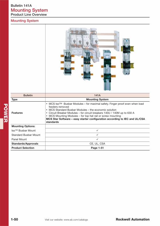
Bulletin 141AMounting System
1-50 Visit our website: www.ab.com/catalogs Rockwell Automation
PO
WE
R
Mounting System
Product Line Overview
Bulletin 141A
Type Mounting System
Features
� MCS IsoTM Busbar Modules – for maximal safety. Finger proof even when loadfeeders removed
� MCS Standard Busbar Modules – the economic solution� Circuit Breaker Modules – for circuit breakers 140U / 140M up to 630 A� MCS Mounting Modules – for top hat rail or screw mountingMCS Star Software – easy starter configuration according to IEC and UL/CSAstandards
Mounting Options:
Iso™ Busbar Mount �
Standard Busbar Mount �
Panel Mount �
Standards/Approvals CE, UL, CSA
Product Selection Page 1-51

Bulletin 141AMounting System
1-51Visit our website: www.ab.com/catalogsRockwell Automation
PO
WE
R
Product Selection
MCS Iso™ Busbar Modules
� System finger proof with load feeders removed� Test position with load circuit isolated� Consists of a device adapter plate carrying the load feeder
components and a busbar module plugging on the busbars� Preferably for use with control plug (please order separately)� Modules with suppy wires – lengths optimized for MCS 140M
motor protection circuit breakers� Modules without wire connections – attachable with connection
clips to form bigger platforms� For plugging on 12, 15, 20, 25, 30 mm x 5/10 mm thick busbars
Description
RatedThermal
Current Ith [A]Width[mm] Rail(s) PQ Cat. No.
MCS IsoTM Busbar Module 200 mmhigh� Universal top hat rail(s)
2545
2
� 141A-SS45RR25
54 � 141A-SS54RR25
4554 � 141A-SS54RR45
63 1 141A-SS63RR45
Withoutelectrical
connections
45
1
� 141A-SS45R
54 1 141A-SS54R
MCS IsoTM Busbar Module 260 mmhigh� Universal top hat rail(s)
2545
2 1
141A-SM45RS25
54 141A-SM54RS25
4554 141A-SM54RS45
63 141A-SM63RS45
Withoutelectrical
connections
45
1 1
141A-SM45S
54 141A-SM54S
63 141A-SM63S
Spacer Modules for MCS Iso™ Busbar ModulesFor spacing of load feeders by 9 mm e.g. for improved cooling. Includingconnection clips.
10 141A-AS9S
Micro Switch with wire connections1 N.C. ContactTo wire in serie with the contactor coils drops out whenunplugging the device adapter plate.
10 141A-AS
� May be ordered in package quantities of 10. Add letter M to the end of the cat. no. (Example: 141A-SS45RM).PQ = Package Quantity

Bulletin 141AMounting System
1-52 Visit our website: www.ab.com/catalogs Rockwell Automation
PO
WE
R
Product Selection
� Modules plug directly onto the busbar� Suitable for use with control plug� Modules with current ratings supply the load current by
means of wire or terminal connections� Modules can form bigger platforms using the
connection clips� For plugging on 12, 15, 20, 25, 30 mm x 5/10 mm thick busbars
DescriptionRated ThermalCurrent Ith [A]
Width[mm] Rail(s) PQ Cat. No.
MCS Standard Busbar Module200 mm high� Universal top hat rail(s)
1M = Metall rail
2545
2
� 141A-GS45RR25
54 � 141A-GS54RR25
4554 � 141A-GS54RR45
63 1 141A-GS63RR45
125(For 140-CMN)
90
1M 1
141A-GS90M125
180 141A-GS180M125
270 141A-GS270M125
125 125 180 1M 1 141A-GS180M125H
Without el.connections(i.e. for Rev.
Starters)
45
1
� 141A-GS45R
54 1 141A-GS54R
72 1 141A-GS72S
81 1 141A-GS81S
MCS Standard Busbar Module260 mm high� Universal top hat rail(s)
2545
2
1
141A-GM45RS25
54 141A-GM54RS25
4554 141A-GM54RS45
63 141A-GM63RS45
Without el.connections(i.e. for Rev.
Starters)
45
1
141A-GM45S
54 141A-GM54S
63 141A-GM63S
MCS Standard Busbar Module with Terminals200 mm high� Universal top hat rail(s)� For mounting various components
25 45
1
1
141A-FS45S25
63
54 141A-FS54S63
63 141A-FS63S63
72 141A-FS72S63
81 141A-FS81S63
MCS Standard Busbar Module with Terminals260 mm high� Universal top hat rail(s)� For mounting various components
25 45
2
141A-FM45SS25
63
54 141A-FM54SS63
63 141A-FM63SS63
72 141A-FM72SS63
81 141A-FM81SS63
Spacer ModuleFor spacing of load feeders by 9 mm e.g. for improved cooling. Includingconnection clips.
10 141A-AS9B
� May be ordered in package quantities of 10. Add letter M to the end of the cat. no. (Example: 141A-GS45RM).

Bulletin 141AMounting System
1-53Visit our website: www.ab.com/catalogsRockwell Automation
PO
WE
R
Product Selection
MCS Standard Busbar Modules >100 A
� Busbar modules >100 A are screw mountedonto the busbars
� Sliding nuts for matching the fixing positions of components� Versions with terminals on top or bottom� For mounting components with current ratings 100 A
(supply and load feeders)� For plugging on 12, 15, 20, 25, 30 mm x 5/10 mm thick busbars
Description
RatedThermal
Current Ith [A]Width[mm] Cat. No.
Standard Busbar Module with Terminals on Top222 mm tallWith box terminals on top for electrical connectionWire size 70 mm2 (2/0 AWG)Universal mounting capability with sliding pocketnuts (M4)
200 108 141A-FS108V200T
Standard Busbar Module with Terminals on Top320 mm tallWith box terminals on top for electrical connectionWire size 120 mm2 (250 MCM)Universal mounting capability with sliding pocketnuts (M4)
250 110 141A-FL110V250T
Standard Busbar Module with FlexibleConnectingWires for electrical connectionFor use with Bulletin 140U circuit breaker (H-Frame)For use with Bulletin 140M circuit breaker (H-Frame)Meets feeder circuit spacings per UL 508A
125 90 141A-CUH125T
125 90 141A-CUH125B
Standard Busbar Module with Rear ConnectingStudsfor electrical connectionFor use with Bulletin 140U circuit breakers (J-, K-or L-Frame)For use with Bulletin 140M circuit breakers (J-, K-or L-Frame)Meets feeder circuit spacings per UL 508A
250(J frame) 105 141A-CUJ250
630(K and Lframes)
140 141A-CUL600

Bulletin 141AMounting System
1-54 Visit our website: www.ab.com/catalogs Rockwell Automation
PO
WE
R
Product Selection
� Modules (carrying the load feeder components) for screwmounting or snapping onto top hat (DIN) rails.
� Control plug optionally (please order separately)� Three module lengths for 2- and 3-component starters.� Modules can form bigger platforms using the connection clips
(see accessories)� Modules with PE - terminal for termination of the motor leads
incl. PE (for mounting on top hat rails only).
Busbar Components
Modules with 2 Rails
MCS Mounting Modules
Description PQ Cat. No.
NH Fuse Switch DisconnectorConnection bottom or topSize 00 for plugging on 5, 10 mm thickand double-T busbars.Sizes 1 and 2 conversion kit 141A-NFAFR5 is required for plugging on 5 mmthick busbars.Size 3 only for plugging on 10 mm anddouble-T busbars.
Size 00200 x 106 mm 70 mm2 160 A 1 141A-NFD160
Size 1243 x 184 mm
M10120 mm2 250 A 1 141A-NFD250
Size 2288 x 210 mm
M10240 mm2 400 A 1 141A-NFD400
Size 3300 x 256 mm
M12240 mm2 630 A 1 141A-NFD630
Pilot SwitchFor NH-fuse switch disconnectorsSignaling ON/OFF position of lid250V AC / 5 A30V DC / 4 A
Size 00…3 1 141A-NFASNFD
Wedge Clamp TerminalFor NH-fuse switch disconnectorsConnection accessories
Size 221 x 15 mm
120…240 mm2 1 141A-NFVF2240
Size 325 x 20 mm
150…300 mm2 1 141A-NFVF3300
Cover for Cable LugsFor NH fuse switch disconnecorCan be clipped on bottom or top
Size 1 2 141A-NFAC1ASize 2 2 141A-NFAC2ASize 3 2 141A-NFAC3A
DescriptionWidth[mm] Cat. No.
MCS Mounting Module 228 mm high� Universal top hat rail(s)� Preferably for 2-component starters
45 141A-WS45RR
54 141A-WS54RR
MCS Mounting Module 228 mm high with PE-Terminal� Universal top hat rail(s)� Preferably for 2-component starters
45 141A-WS45RRP
54 141A-WS54RRP
MCS Mounting Module 283 mm high� Universal top hat rail(s)� Preferably for 3-component starters with overload relays 193-ED/EE
45 141A-WM45RR
54 141A-WM54RR
MCS Mounting Module 283 mm high with PE-Terminal� Universal top hat rail(s)� Preferably for 3-component starters with overload relays 193-ED/EE
45 141A-WM45RRP
54 141A-WM54RRP
MCS Mounting Module 333 mm high� Universal top hat rail(s)� Preferably for 3-component starters with overload relays 193-EC
45 141A-WL45RR
54 141A-WL54RR
MCS Mounting Module 333 mm high with PE-Terminal� Universal top hat rail(s)� Preferably for 3-component starters with overload relays 193-EC
45 141A-WL45RRP
54 141A-WL54RRP
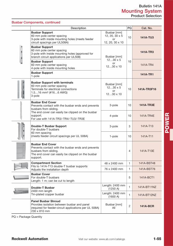
Bulletin 141AMounting System
1-55Visit our website: www.ab.com/catalogsRockwell Automation
PO
WE
R
Product Selection
Busbar Components, continued
Description PQ Cat. No.
Busbar Support60 mm pole center spacing3-pole with inside mounting holes (meets feedercircuit spacings per UL508A)
Busbar [mm]12, 20, 30 x 5
or12, 20, 30 x 10
10 141A-TU3
Busbar Support60 mm pole center spacing3-pole with inside mounting holes (approved forbranch circuit applications per UL508) Busbar [mm]
12…30 x 5or
12…30 x 10
10
141A-TR3
Busbar Support60 mm pole center spacing4-pole with inside mounting holes
141A-TR4
Busbar Support1-pole 141A-TR1
Busbar Support with terminals60 mm pole center spacingTerminals for electrical connections1.5…16 mm2 (#16…6 AWG)3-pole
Busbar [mm]12…30 x 5
or12…30 x 10
10 141A-TR3F16
Busbar End CoverPrevents contact with the busbar ends and preventsbusbars from sliding.The end cover can easily be clipped on the busbarsupport.For use with 141A-TR3/-TR4/-TU3/-TR3E
3-pole 10 141A-TR3E
4-pole 10 141A-TR4E
Double-T Busbar SupportFor double-T busbars60 mm spacing(meets feeder circuit spacings per UL 508A)
3-pole 3 141A-T13
1-pole 10 141A-T11
Busbar End CoverPrevents contact with the busbar ends and preventsbusbars from sliding.The end cover can easily be clipped on the busbarsupport.
4 141A-T13E
Compartment SectionFits to 141A-T13 double-T busbar supportsAdjusts the installation depth
48 x 2400 mm 1 141A-BST48
76 x 2400 mm 1 141A-BST76
Busbar CoverFor double-T busbarsLength: 1 m; can be cut to length
5 141A-BCT1
Double-T Busbar2400 mm length Tin-plated copper busbar
Length: 2400 mm(1250 A) 1 141A-BT11NZ
Length: 2400 mm(1600 A) 1 141A-BT12NZ
Panel Busbar ShroudProvides isolation between busbar and panel(required for feeder-circuit applications per UL 508A)230 x 810 mm
Busbar [mm]All 2 141A-BCR
PQ = Package Quantity

Bulletin 141AMounting System
1-56 Visit our website: www.ab.com/catalogs Rockwell Automation
PO
WE
R
Product Selection
Busbar Components, continued
Description Busbar [mm] PQ Cat. No.
Supply Module3-pole6…50 mm2 (10…1/0 AWG)54 mm wide(meets feeder circuit spacings per UL 508A) 12…30 x 5
or12…30 x 10
1
141A-VN370
Supply Module3-pole35…120 mm2 (2 AWG…250 MCM)81 mm wide(meets feeder circuit spacings per UL 508A)
141A-VN3120
Supply Module3-pole95…185 mm2 (3/0 AWG…350 MCM)135 mm wide
141A-VN3185
Supply Module3-polefor round conductors150…300 mm2 (300…600 MCM)135 mm wide
141A-VN3300R
Supply Module3-polefor flat conductors up to 32 x 20 mmequivalent to 300 mm2 (300…600 MCM) round conductor ampacity135 mm wide
141A-VN3300F
Supply Module3-Pole (set of 3 terminals)for round conductors120…300 mm2 (250…600 MCM)153 mm wide (3 single poles of 51 mm each)(meets feeder circuit spacings per UL 508A)Requires Cat. No. 141A-BK180, 141A-BK228 or 141A-BK250 terminal cover
1
141A-VU3300R
Supply Module3-Pole (set of 3 terminals)for flat conductors up to 32x20 mmequivalent to 300 mm2 (600 MCM)153 mm wide (3 single poles of 51 mm each)(meets feeder circuit spacings per UL 508A)Requires Cat. No. 141A-BK180, 141A-BK228 or 141A-BK250 terminal cover
141A-VU3300F
Single TerminalsSingle terminals for supplying busbars2.5…16 mm2 (#14…6 AWG)
12…30 x 5 25 141A-VS116
12…30 x 10 25 141A-VS216
Single TerminalsSingle terminals for supplying busbars4…35 mm2 (#12…2 AWG)
12…30 x 5 25 141A-VS135
12…30 x 10 25 141A-VS235
Single TerminalsSingle terminals for supplying busbars16…70 mm2 (#6…2/0 AWG)
12…30 x 5 25 141A-VS170
12…30 x 10 25 141A-VS270
Single TerminalsSingle terminals for supplying busbars16…120 mm2 ( #6…250 MCM)
12…30 x 10 25 141A-VS2120
Profile TerminalsFor double-T busbarsTo connect with flat busbars andflexible copper busbars
400…800 mm2For use up to:
1600 A
3 141A-VS54136F500…750 mm2 3 141A-VS55121F600…900 mm2 3 141A-VS56421F600…1200 mm2 1600 A / 2000 A � 3 141A-VS56436F800…1600 mm2 1600 A / 2500 A � 3 141A-VS58136F
1000…2000 mm2 1600 A / 2800 A � 3 141A-VS510136F
� >1600 A only for centre feeding

Bulletin 141AMounting System
1-57Visit our website: www.ab.com/catalogsRockwell Automation
PO
WE
R
Busbar Components, continued
Product Selection
Description Busbar [mm] PQ Cat. No.
Terminal CoverFinger protection when busbars supplied with singleterminals. Attaches directly to busbars.Height: 180 mm, Width: 54 mm
12…30 x 5or
12…30 x 101 141A-BK1
Terminal CoverFinger protection when bus bars are supplied byCat. No. 141A-VU3300_ supply moduleAttaches directly to bus barsHeight: 200 mmDepth: 90 mm
180 x 200 x 90
1
141A-BK180
228 x 200 x 90 141A-BK228
250 x 200 x 90 141A-BK250
Components for Terminal / Busbar Covers of individual length
Set of Busbar Shroud Holders 1 left, 1 right side
1
141A-BKH
Busbar Shroud Profile 1 x 1.1 m 141A-BKC
Top / Bottom Busbar Shroud Profile 2 x 1.1 m 141A-BKS
Busbar ConnectorSystem distance: 5…10 mm
12…20 x 5or
12…20 x 1012 141A-VC3A
Busbar Shroud Cover200 x 1100 mmCovers all three busbars
12…30 x 5 or12…30 x 10 2 141A-BCF1
Busbar Shroud Holder Two required per section of Busbar Shroud Cover
12…30 x 5 or12…30 x 10 10 141A-BCF1H
Double-T Busbar ConnectorsFor connection of double-T busbar racks with samedimensions, Width: 95 mm
Double-T 3
141A-VC5F
Double-T Busbar ConnectorsFor connection of double-T busbar racks with samedimensions, Width: 150 mm
141A-VC5G
Single Pole Busbar CoversSnap-on profile for single busbars for protectionagainst electric shock.Length: 1 m, can be cut to length.
12…30 x 510
141A-BS5
12…30 x 10 141A-BS10
Hat (DIN) Rails — MCS Top Hat Rail (Plastic)Slides onto mounting modules and is then fixed withscrews.Has notches for MCS components (preventsmovement of components when used with verticalbusbar).
45
10
141A-AHR45
54 141A-AHR54
63 141A-AHR63
Control PlugPull-apart terminal block allows fast and simpledisconnection of control wiring.Snaps on the support of the mobile device rail.Composed of plug holder, male and female parts.
8 Pole
1�
141A-APC8
10 Pole 141A-APC10
12 Pole 141A-APC12
Control Plug HolderSuitable for use with 8-, 10-, or 12-pole control plugs. 1 141A-APH
Connection ClipFor joining base of mounting modules. 50 141A-AK
� May be ordered in package quantities of 10. Add letter M to the end of the Cat. No. (Example: 141A-APC8M).PQ = Package Quantity

Bulletin 193, 825-P, 809, 813, 817, 819 Motor Protection
1-58 Visit our website: www.ab.com/catalogs Rockwell Automation
PO
WE
R
Product Line Overview
Overload Relays
Bulletin 193-K 193-T1 193-ED 193-EE
Type Miniature ThermalOverload Relay
Bimetallic OverloadRelays
Electronic Overload Relay,E1 Plus
Rated Current(Range) 0.1…12.5 A 0.1…90 A 0.1…45 A 0.1… 800 A
Operating Voltage,Nominal 690V 690V 690V
690V AC (IEC)/ 600V AC (CSA/UL) �
1000V AC (IEC)/ 600V AC (CSA/UL) �
Overload Type Bimetallic Bimetallic Solid State Solid State
Trip Class (Fixed) 10A 10A 10 —
Trip Class(Adjustable) — — — 10, 15, 20 or 30
AmbientCompensated � � � �
Reset Type Automatic andManual
Automatic andManual Manual Manual /
Auto-Manual
Adjustment Range 1.5:1 1.5:1 5:1 5:1
Phase LossNormal Sensing
w/differentialmechanism
Normal Sensingw/differentialmechanism
Enhanced Sensing Enhanced Sensing
Trip Contact N.C. � � � �
Alarm Contact N.O. � � � �
Mounts toContactor 100-K 100-C 100-C 100-C, 100-D
Product Selection See page 1-61 See page 1-62 See page 1-64 See page 1-64
� 193-EE_B, 193-EE_D, 193-EEGE� 193-EE_F, 193-EE_G, 193-EE_H

Bulletin 193, 825-P, 809, 813, 817, 819Motor Protection
1-59Visit our website: www.ab.com/catalogsRockwell Automation
PO
WE
R
Overload Relays
Product Line Overview
Bulletin 193-EC1/-EC2/-EC3/-EC4/-EC5 825-P
Type Electronic Overload Relay E3 and E3 Plus Modular Protection System
Rated Current (Range) 0.4…5000 A 0.5…5000 A
Operating Voltage, Nominal 690V / 1000V � 690V/1000V
Overload Type � Microprocessor Based Microprocessor Based
Trip Class (Adjustable) � 5…30 1…600
Ambient Compensated � �
Reset Type �Automatic, Manual and
RemoteAutomatic, Manual and
Remote
Adjustment Range � 5:1 4:1
Phase Loss Imbalance Sensing Imbalance Sensing
Phase Reversal — �
Ground (Earth) Fault E3 Plus: Sensitive Residual or Sensitive
Overcurrent (Jam) Detection � �
Stall Detection � �
Starts/Hour Monitoring � �
Underload Detection � �
Current Imbalance � �
Short Circuit Protection — �
PTC Thermistor Monitoring � (EC2/EC3) �
RTD Monitoring — 12-Channel Optional Scanner
Warning Settings � �
Trip Contact N.C. � �
Alarm Contact N.O. � �
Number of Outputs E3: 1/E3 Plus: 2 3 (Basic)/7 (with I/O Expansion)
Number of Inputs E3: 2/E3 Plus: 4 2 (Basic)/5 (with I/O Expansion)
Number of Analog Outputs — 1(with I/O Expansion)
ODVA (DeviceNet)Conformance � �
Atex Certification In Preparation —
Variable Frequency(VFD) Compatible � —
Mounts to Contactor 100-C, 100-D 100-D (825-MCM)
Product Selection See page 1-68 See page 1-71
� 193-EC_F, 193-EC_G, 193-EC_H� not for 193-EC4 (no overload protection)

Bulletin 193, 825-P, 809, 813, 817, 819 Motor Protection
1-60 Visit our website: www.ab.com/catalogs Rockwell Automation
PO
WE
R
Product Line Overview
Monitoring Relays
Bulletin 809S 813S 813S 814S 814S 817S
Type
CurrentMonitoring
Relays
VoltageMonitoring
Relays
PowerFactorRelays
Power(kW)
Relays
ThermistorMonitoring
Relay
Single Phase Single Phase Three Phase Three Phase Three Phase Three Phase
Operating range
1…10 AAC/DC
2…500VAC/DC
380…415VAC
1…10 AAC
1…10 AAC
24/48VAC/DC
24/48VAC/DC
24/48VAC/DC
440…480VAC
380…480VAC
380…480VAC
115VAC
115/230VAC
115/230VAC
600…690VAC
600…690VAC
600…690VAC
230VAC
Under- and overcurrentprotection � — — — — —
Under- and overvoltageprotection — � � — — —
Phase loss protection — — � — — —
Phase imbalance — — � — — —
Phase reversal — — � — — —
Under- and over activepower (kW) protection — — — — � —
Overtemperatureprotection — — — — — �
Adjustable time delaysettings � � � � � —
Programmable latchingor inhibit at set level � � — � � —
Changeover contacts(SPDT) 1 1 2 1 1 1
Automatic reset � � � � � �
LED status indicator � � � � � �
Dimensions:W: [mm]H: [mm]D: [mm]
22.580
99.5
22.580
99.5
4580
99.5
4580
99.5
4580
99.5
22.580
99.5
Product Selection See page 1-73

Bulletin193-KMotor Protection
1-61Visit our website: www.ab.com/catalogsRockwell Automation
PO
WE
R
Miniature Bimetallic Overload Relays 193-K
Product Selection
Mounts to ContactorSetting Range [A]
��
Max. Current Rating Backup gL Fuse[A]
IEC Coordination Type
Cat. No.Type 1 Type 2
100-K05…100-K12
0.10…0.16 35 1 193-KA16
0.16…0.25 35 1 193-KA25
0.25…0.40 35 2 193-KA40
0.35…0.50 35 2 193-KA50
0.45…0.63 35 2 193-KA63
0.55…0.80 35 4 193-KA80
0.75…1.0 35 4 193-KB10
0.9…1.3 35 6 193-KB13
1.1…1.6 35 6 193-KB16
1.4…2.0 35 10 193-KB20
1.8…2.5 35 20 193-KB25
2.3…3.2 35 20 193-KB32
2.9…4.0 35 20 193-KB40
3.5…4.8 35 20 193-KB48
4.5…6.3 35 20 193-KB63
100-K09…100-K125.5…7.5 35 20 193-KB75
7.2…10.0 35 20 193-KC10
100-K12 9.0…12.5 35 20 193-KC12
� To select the setting range for use in Y-Δ Starters, multiply the rated operating current of the motor by a factor of0.58.
� For motors with service factor of 1.15 or greater, use motor nameplate full load current. For motors with servicefactor of 1.0, use 90% of the motor nameplate full load current.
� Standard Motor Protection for AC and DC Motors� Overload Protection Trip class 10A� Auxiliary Switch (1 N.O. and 1 N.C.)� Phase Loss Sensitivity� Manual/Auto Reset Button� Test/Stop Button� Trip Indicator

Bulletin 193-T1Motor Protection
1-62 Visit our website: www.ab.com/catalogs Rockwell Automation
PO
WE
R
Bimetallic Overload Relays 193-T1
Product Selection
� Overload protection trip class 10 / 10A� Phase loss protection� Ambient temperature compensation� Auxiliary contacts (1 N.O. and 1 N.C.)� Manual/automatic reset mode selectable� Test function for auxiliary contacts� Stop button� Trip Indicator� Optional remote reset solenoid and external reset accessories
For Use With �
Setting Range[A]�‡
Max. Back-up gL/gG fuse [A]50 kA, 690V AC
IEC/EN 60947-4-1 CoordinationCat. No.Type 1 Type 2
100-C09…100-C23
0.1…0.16 50 — 193-T1AA160.16…0.25 50 — 193-T1AA250.25…0.40 50 2 193-T1AA400.35…0.50 50 2 193-T1AA500.45…0.63 50 2 193-T1AA630.55…0.80 50 4 193-T1AA800.75…1.0 50 4 193-T1AB100.90…1.3 50 6 193-T1AB131.1…1.6 50 6 193-T1AB161.4…2.0 50 10 193-T1AB201.8…2.5 50 16 193-T1AB252.3…3.2 50 16 193-T1AB322.9…4.0 50 16 193-T1AB403.5…4.8 50 16 193-T1AB484.5…6.3 50 20 193-T1AB635.5…7.5 50 25 193-T1AB757.2…10 50 25 193-T1AC10
9.0…12.5 50 35 193-T1AC12100-C12…100-C23 11.3…16 50 35 193-T1AC16
100-C16…100-C2315…20 80 40 193-T1AC20
17.5…21.5 80 50 193-T1AC21100-C23 21…25 80 50 193-T1AC25
100-C30…100-C37
15…20 80 40 193-T1BC2017.5…21.5 80 50 193-T1BC21
21…25 80 50 193-T1BC2524.5…30 100 63 193-T1BC3029…36 125 63 193-T1BC36
100-C37 33…38 125 63 193-T1BC38
100-C4317…25 100 50 193-T1CC25
24.5…36 125 80 193-T1CC3635…47 160 100 193-T1CC47
100-C60…100-C8535…47 160 100 193-T1DC4745…60 200 125 193-T1DC60
100-C72…100-C85 58…75 200 125 193-T1DC75100-C85 72…90 250 160 193-T1DC90

Bulletin 193-T1Motor Protection
1-63Visit our website: www.ab.com/catalogsRockwell Automation
PO
WE
R
Thermal Overload Relays, continued
For Use With �
Setting Range[A]�‡
Max. Back-up gL/gG fuse [A]50 kA, 690V AC
IEC/EN 60947-4-1 Coordination
Cat. No.Type 1 Type 2
Separate mounting required(Panel-mounted device)
35…47 160 100 193-T1DC47P
45…60 200 125 193-T1DC60P
58…75 200 125 193-T1DC75P
72…90 250 160 193-T1DC90P
� Bulletin 193-T1 overload relays shall not be used with conventional DC controlled contactors. Use electroniccontrolled DC versions.
� To select the setting range for use in Y-Δ Starters, multiply the rated operating current of the motor by a factor of0.58.
‡ For motors with service factor of 1.15 or greater, use motor nameplate full load current. For motors with servicefactor of 1.0, use 90% of the motor nameplate full load current.
Add-On Modules
Product Selection / Accessories
Description For Use With PQ Cat. No.
DIN Rail/Panel Mounting AdapterFor separate mounting of overload relaysSnaps on to 35 mm top hat rail
193-T1AA, 193-T1AB,193-T1AC, 193-T1BC 1 193-T1APM
Screw AdapterFor screw fixing of the 193-T1APM paneladapter (1 required per adapter)
193-T1APM 10�
140M-C-N45
Remote Reset SolenoidFor remote reset of 193-K and 193-T1overload relays
193-K, 193-T1 (notfor 193-T1DC_P) 1 193-T1R⊗
External Reset ButtonFor enclosed, through-the-door resetapplications. Metal construction, IP66, non-illuminated. Refer to the 800F selectioninformation for additional types.
All 1 800FM-R611
Reset RodLength 142 mm, adjustable range141…159 mm
All 1 800F-ATR08
Reset AdapterExpands the reset target area when usingan external reset
193-K, 193-T1 (notfor 193-T1DC_P) 1 193-RA3
� Must be ordered in multiples of package quantity.PQ = Package Quantity
⊗ Coil Voltage Codes for Remote Reset Solenoid
[V] 24 48 110 120 125 220…24050 Hz — — D — — —60 Hz — — — D — —
50/60 Hz KJ KY — — — KFDC ZJ ZY ZD — ZS —

Bulletin 193-ED, 193-EEMotor Protection
1-64 Visit our website: www.ab.com/catalogs Rockwell Automation
PO
WE
R
Electronic Overload Relays E1 Plus - 193-ED, 193-EE
Product Selection
� Self-Powered� Fast Phase Loss Protection� Wide Adjustment Range (5:1)� Insert-Molded Power Connections� 1 N.O. and 1 N.C. Isolated Auxiliary Contacts
(B600, AC-15 Rated)� Low Energy Consumption (150 mW)� Ambient Temperature Compensation� Visible Trip Indication� Optional accessories for expanded functionality
Standardversion
Pass-throughversion
Description Mounts to Contactor Adjustment Range [A] Cat. No.
Three-Phase Devices 193-ED
� 0.1…45 A Current Range� Fixed Trip Class 10� Manual Reset
100-C09…100-C23
0.1…0.5 193-ED1AB
0.2…1.0 193-ED1BB
1.0…5.0 193-ED1CB
3.2…16 193-ED1DB
5.4…27 193-ED1EB
100-C30…100-C435.4…27 193-ED1ED
9…45 193-ED1FD
� 1…27 A Current Range� Selectable Trip Class (10, 15, 20 or 30)� Selectable Manual/Auto-Manual Reset
Integrated panel/DINRail mount and pass-
thru wiring
1.0…5.0 193-ED1CP
3.2…16 193-ED1DP
5.4…27 193-ED1EP
Three-Phase Devices 193-EE
� 0.1…800 A Current Range� Selectable Trip Class (10, 15, 20 or 30)� Selectable Manual/Auto-Manual Reset
100-C09…100-C23
0.1…0.5 193-EEAB
0.2…1.0 193-EEBB
1.0…5.0 193-EECB
3.2…16 193-EEDB
5.4…27 193-EEEB
100-C30…100-C435.4…27 193-EEED
9…45 193-EEFD
100-C60…100-C85
5.4…27 193-EEEE
9…45 193-EEFE
18…90 193-EEGE
100-D95…100-D18030…150 � 193-EEHF
40…200 � 193-EEJF
100-D210…100-D42040…200 � 193-EEJG
60…300 � 193-EEKG
100-D210…100-D420 100…500 � 193-EELG
100-D630…100-D860 120…600 � 193-EEMH
100-D630…100-D860 160…800 � 193-EENH
Three-Phase Devices 193-EE
� 1…27 A Current Range� Selectable Trip Class (10, 15, 20 or 30)� Selectable Manual/Auto-Manual Reset
Integrated panel/DINRail mount and pass-
thru wiring
1.0…5.0 193-EECP
3.2…16 193-EEDP
5.4…27 193-EEEP
� Rated operating voltage IEC: 1000V AC
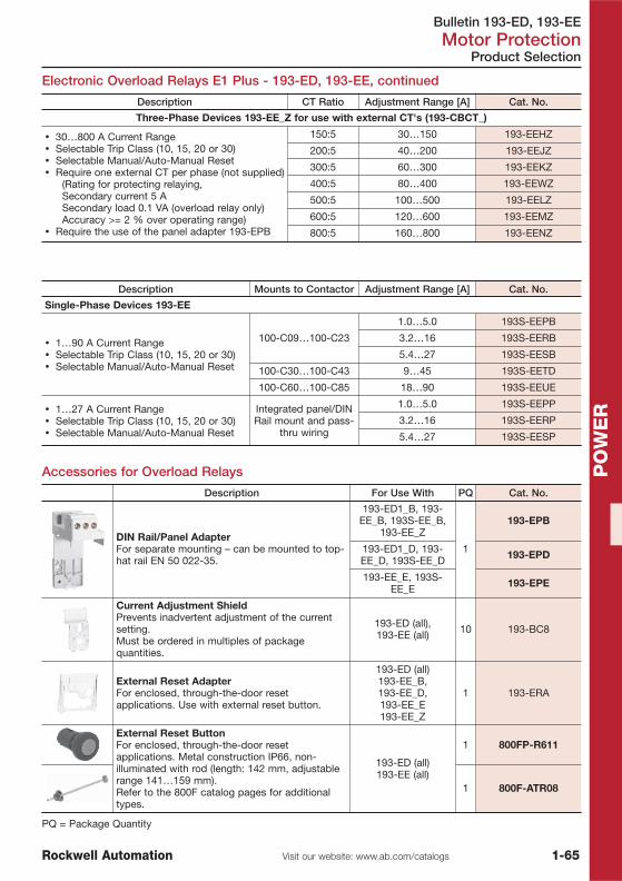
Bulletin 193-ED, 193-EEMotor Protection
1-65Visit our website: www.ab.com/catalogsRockwell Automation
PO
WE
R
Electronic Overload Relays E1 Plus - 193-ED, 193-EE, continued
Product Selection
Description CT Ratio Adjustment Range [A] Cat. No.
Three-Phase Devices 193-EE_Z for use with external CT's (193-CBCT_)
� 30…800 A Current Range� Selectable Trip Class (10, 15, 20 or 30)� Selectable Manual/Auto-Manual Reset� Require one external CT per phase (not supplied)
(Rating for protecting relaying,Secondary current 5 ASecondary load 0.1 VA (overload relay only)Accuracy >= 2 % over operating range)
� Require the use of the panel adapter 193-EPB
150:5 30…150 193-EEHZ
200:5 40…200 193-EEJZ
300:5 60…300 193-EEKZ
400:5 80…400 193-EEWZ
500:5 100…500 193-EELZ
600:5 120…600 193-EEMZ
800:5 160…800 193-EENZ
Description Mounts to Contactor Adjustment Range [A] Cat. No.
Single-Phase Devices 193-EE
� 1…90 A Current Range� Selectable Trip Class (10, 15, 20 or 30)� Selectable Manual/Auto-Manual Reset
100-C09…100-C23
1.0…5.0 193S-EEPB
3.2…16 193S-EERB
5.4…27 193S-EESB
100-C30…100-C43 9…45 193S-EETD
100-C60…100-C85 18…90 193S-EEUE
� 1…27 A Current Range� Selectable Trip Class (10, 15, 20 or 30)� Selectable Manual/Auto-Manual Reset
Integrated panel/DINRail mount and pass-
thru wiring
1.0…5.0 193S-EEPP
3.2…16 193S-EERP
5.4…27 193S-EESP
Accessories for Overload Relays
Description For Use With PQ Cat. No.
DIN Rail/Panel AdapterFor separate mounting – can be mounted to top-hat rail EN 50 022-35.
193-ED1_B, 193-EE_B, 193S-EE_B,
193-EE_Z
1
193-EPB
193-ED1_D, 193-EE_D, 193S-EE_D 193-EPD
193-EE_E, 193S-EE_E 193-EPE
Current Adjustment ShieldPrevents inadvertent adjustment of the currentsetting.Must be ordered in multiples of packagequantities.
193-ED (all),193-EE (all) 10 193-BC8
External Reset AdapterFor enclosed, through-the-door resetapplications. Use with external reset button.
193-ED (all)193-EE_B,193-EE_D,193-EE_E193-EE_Z
1 193-ERA
External Reset ButtonFor enclosed, through-the-door resetapplications. Metal construction IP66, non-illuminated with rod (length: 142 mm, adjustablerange 141…159 mm).Refer to the 800F catalog pages for additionaltypes.
193-ED (all)193-EE (all)
1 800FP-R611
1 800F-ATR08
PQ = Package Quantity
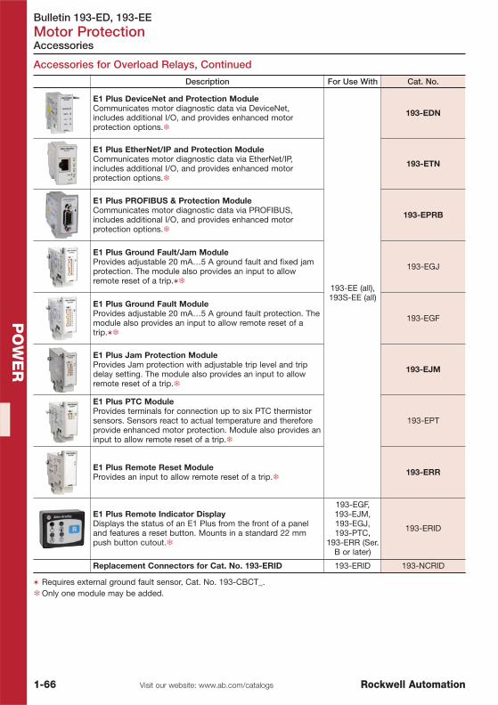
Bulletin 193-ED, 193-EEMotor Protection
1-66 Visit our website: www.ab.com/catalogs Rockwell Automation
PO
WE
R
Accessories
Accessories for Overload Relays, Continued
Description For Use With Cat. No.
E1 Plus DeviceNet and Protection ModuleCommunicates motor diagnostic data via DeviceNet,includes additional I/O, and provides enhanced motorprotection options.�
193-EE (all),193S-EE (all)
193-EDN
E1 Plus EtherNet/IP and Protection ModuleCommunicates motor diagnostic data via EtherNet/IP,includes additional I/O, and provides enhanced motorprotection options.�
193-ETN
E1 Plus PROFIBUS & Protection ModuleCommunicates motor diagnostic data via PROFIBUS,includes additional I/O, and provides enhanced motorprotection options.�
193-EPRB
E1 Plus Ground Fault/Jam ModuleProvides adjustable 20 mA…5 A ground fault and fixed jamprotection. The module also provides an input to allowremote reset of a trip.��
193-EGJ
E1 Plus Ground Fault ModuleProvides adjustable 20 mA…5 A ground fault protection. Themodule also provides an input to allow remote reset of atrip.��
193-EGF
E1 Plus Jam Protection ModuleProvides Jam protection with adjustable trip level and tripdelay setting. The module also provides an input to allowremote reset of a trip.�
193-EJM
E1 Plus PTC ModuleProvides terminals for connection up to six PTC thermistorsensors. Sensors react to actual temperature and thereforeprovide enhanced motor protection. Module also provides aninput to allow remote reset of a trip.�
193-EPT
E1 Plus Remote Reset ModuleProvides an input to allow remote reset of a trip.� 193-ERR
E1 Plus Remote Indicator DisplayDisplays the status of an E1 Plus from the front of a paneland features a reset button. Mounts in a standard 22 mmpush button cutout.�
193-EGF,193-EJM,193-EGJ,193-PTC,
193-ERR (Ser.B or later)
193-ERID
Replacement Connectors for Cat. No. 193-ERID 193-ERID 193-NCRID
� Requires external ground fault sensor, Cat. No. 193-CBCT_.�Only one module may be added.

Bulletin 193-ED, 193-EEMotor Protection
1-67Visit our website: www.ab.com/catalogsRockwell Automation
PO
WE
R
Accessories
Accessories for Overload Relays, Continued
Description For Use With Cat. No.
Core Balanced GroundFault Sensor� Required when using
either an E1 PlusGround Fault Protectionor Ground Fault/JamModule
� Required for groundfault protection with theCat. No. 193-EC3_ _overload relay
20 mm (0.79 in.) 100-C09…100-C37 193-CBCT1
40 mm (1.57 in.) 100-C09…100-C85 193-CBCT2
63 mm (2.5 in.)100-C09…100-C85,
100-D95…100-D180
193-CBCT3
82 mm (3.25 in.)100-C09…100-C85,
100-D95…100-D420
193-CBCT4
DeviceNet Configuration TerminalUsed to interface with objects on a DeviceNetnetwork. Includes 1 m communications cable (193-CB1).
DeviceNet 193-DNCT
1 meter communication cable, color-coded bareleads
193-DNCT
193-CB1
1 meter communication cable, microconnector(male) 193-CM1
Panel Mount Adapter/Door Mount Bezel Kit 193-DNCT-BZ1
Remote Reset Solenoid
24V AC, 50/60 Hz
E1 Plus (all)
193-EMRJ
110/120V AC, 50/60 Hz 193-EMRD
220/240V AC, 50/60 Hz 193-EMRA
24V DC 193-EMRZ24
48V DC 193-EMRZ48
115V DC 193-EMRZ01
Description For Use With Cat. No.
Terminal LugsSet of twoProtection class IP2X per IEC 60529 andDIN 40050
100-D140, 100-D180, 100-D95E…D180E, 193-EC_F, 193-
EE_F100-DTB180
100-D210...100-D420, 193-EC_G, 193-EF2C, 193-EE_G 100-DTB420
Terminal CoversProtection class IP20 per IEC 60529 andDIN 40 050For direct-on-line, reversing, two-speed,and wye-delta/star-delta assemblies
100-D95…100-D180, 193-EC_F,193-EE_F 100-DTC180
100-D210...100-D420, 193-EC_G, 193-EE_G 100-DTC420
100-D630…100-D860, 193-EC_H, 193-EE_H 100-DTC860
100-D630…100-D860, 193-EC_H, 193-EE_H 100-DTCS860
Terminal Lugs (UL/CSA), Copper FrameSet of three
100-D140, 100-D180, 193-EC_F,193-EE_F 100-DL180
100-D210…100-D420, 193-EC_G, 193-EE_G 100-DL420
100-D630, 100-D860, 193-EC_H, 193-EE_H 100-DL630
100-D630, 100-D860, 193-EC_H, 193-EE_H 100-DL860
Note: For labeling materials, see page 1-34.

Bulletin 193-ECMotor Protection
1-68 Visit our website: www.ab.com/catalogs Rockwell Automation
PO
WE
R
Product Selection
E3 and E3 Plus Electronic Overload & Current Monitor Relays
� DeviceNet™ communication integrated� IEC/NEMA configurations� True RMS current sensing� Single-/three-phase� LED indicators� Test/reset button� Adjustable trip class (5…30)� Motor Diagnostics
BulletinNo.
InputsNo.
OutputsPM
DiagnosticsPTC
Thermistor DeviceLogix Ground Fault
193-EC1 2 1 � — — —
193-EC2 4 2 � � �Internal(1…5 A)
193-EC3 4 2 � � �External �
(20 mA…5 A)
193-EC4 � 4 2 � � �External �
(20 mA…5 A)
� The Bul. 193-EC4 is a current monitor relay for three independent current signals. Thermal overload motorprotection is not provided.
� External ground fault sensor, Cat. No. 193-CBCT_, required
Electronic Motor Protection Relays 193-EC1 – Direct Contactor Mount
Mounts to Contactor Adjustment Range [A] Cat. No.
100-C09…100-C23
0.4…2 193-EC1PB
1…5 193-EC1AB
3…15 193-EC1BB
5…25 193-EC1CB
100-C30…100-C43
1…5 193-EC1AD
3…15 193-EC1BD
5…25 193-EC1CD
9…45 193-EC1DD
100-C60…100-C859…45 193-EC1DE
18…90 193-EC1EE
100-D95…100-D18028…140 � 193-EC1FF
42…210 � 193-EC1GF
100-D210…100-D420
42…210 � 193-EC1GG
60…302 � 193-EC1HG
84…420 � 193-EC1JG
100-D630…100-D860125…630 � 193-EC1KH
172…860 � 193-EC1LH
� Does not include terminal lugs.Rated operating voltage IEC: 1000V AC.

Bulletin 193-ECMotor Protection
1-69Visit our website: www.ab.com/catalogsRockwell Automation
PO
WE
R
Product Selection
Electronic Motor Protection Relay 193-EC2 – Direct Contactor Mount
Mounts to Contactor Adjustment Range [A] Cat. No.
100-C09…100-C23
0.4…2 193-EC2PB1…5 193-EC2AB3…15 193-EC2BB5…25 193-EC2CB
100-C30…100-C43
1…5 193-EC2AD3…15 193-EC2BD5…25 193-EC2CD9…45 193-EC2DD
100-C60…100-C859…45 193-EC2DE18…90 193-EC2EE
Current Monitor Relays 193-EC4 – Direct Contactor Mount
Mounts to Contactor Adjustment Range [A] Cat. No.
100-C09…100-C23
0.4…2.0 193-EC4PB1…5 193-EC4AB3…15 193-EC4BB5…25 193-EC4CB
100-C30…100-C43 9…45 193-EC4DD100-C60…100-C85 18…90 193-EC4EE
Panel Mount Devices for use with External Current Transformers
For Use With Adjustment Range [A] § Cat. No.
193-ECPM2 DIN Rail/Panel Adapter(Order panel adapter 193-ECPM2 separately) 9…5000
193-EC1ZZ193-EC3ZZ193-EC4ZZ193-EC5ZZ
§ Current transformers supplied by customer. Refer to CT chart for proper current transformer selection.
Mounts to ContactorAdjustment Range
[A]Bul. 193-EC3 Bul. 193-EC5
Cat. No. Cat. No.
100-C09…100-C23
0.4…2.0 193-EC3PB 193-EC5PB1…5 193-EC3AB 193-EC5AB3…15 193-EC3BB 193-EC5BB5…25 193-EC3CB 193-EC5CB
100-C30…100-C435…25 193-EC3CD 193-EC5CD9…45 193-EC3DD 193-EC5DD
100-C60…100-C859…45 193-EC3DE 193-EC5DE18…90 193-EC3EE 193-EC5EE
100-D95…100-D18028…140 � 193-EC3FF 193-EC5FF42…210 � 193-EC3GF 193-EC5GF
100-D210…100-D42042…210 � 193-EC3GG 193-EC5GG60…302 � 193-EC3HG 193-EC5HG84…420 � 193-EC3JG 193-EC5JG
100-D630…100-D860125…630 � 193-EC3KH 193-EC5KH172…860 � 193-EC3LH 193-EC5LH
� Does not include terminal lugs.Rated operating voltage IEC: 1000V AC.
Electronic Overload Relays 193-EC3 / -EC5 – Direct Contactor Mount

Bulletin 193-ECMotor Protection
1-70 Visit our website: www.ab.com/catalogs Rockwell Automation
PO
WE
R
Accessories
CT Ratio to FLA Setting Range Correlation
Add-on Accessories
Description For Use With Cat. No.DeviceNet Configuration TerminalUsed to interface with objects on a DeviceNetnetwork. Includes 1 m communications cable(193-CB1).193-CB1 cable included.
DeviceNet 193-DNCT
1 meter communication cable, color-codedbare leads 193-DNCT 193-CB1
1 meter communication cable,microconnector (male) M12 193-DNCT 193-CM1
Panel Mount Adapter/Door Mount Bezel Kitfor door mounting 193-DNCT 193-DNCT-BZ1
DIN Rail/Panel Adapter �
193-EC__B 193-ECPM1
193-EC_D, 193-EC_ZZ,193-EC_ZZ 193-ECPM2
193-EC__E 193-ECPM3
AC Input Interface Modulerated 110/120V AC, 50/60 Hz
193-EC — all592-EC — all 193-EIMD
Core Balanced GroundFault Sensor� Required when using
either an E1 PlusGround FaultProtection or GroundFault/Jam Module
� Required for groundfault protection withthe Cat. No. 193-EC3__ overload relay
Max. current 45 AHole diameter 20 mm 100-C09…100-C37 193-CBCT1
Max. current 90 AHole diameter 40 mm 100-C09…100-C85 193-CBCT2
Max. current 180 AHole diameter 63 mm
100-C09…100-C85,100-D95…100-D180 193-CBCT3
Max. current 420 AHole diameter 82 mm
100-C09…100-C85,100-D95…100-D420 193-CBCT4
Terminal LugsSet of twoProtection class IP2X per IEC 60529 andDIN 40050
100-D140, 100-D180,100-D95E…D180E,193-EC_F, 193-EE_F
100-DTB180
100-D210...100-D420,193-EC_G, 193-EF2C,
193-EE_G100-DTB420
Terminal CoversProtection class IP20 per IEC 60529 and DIN 40050For direct-on-line, reversing, two-speed, andwye-delta/star-delta assemblies
100-D95…100-D180,193-EC_F, 193-EE_F 100-DTC180
100-D210...100-D420,193-EC_G, 193-EE_G 100-DTC420
100-D630…100-D860,193-EC_H, 193-EE_H 100-DTC860
Phase BarriersSet of 4
100-D630…D860, 193-EC_H, 193-EE_H 100-DPB860
� The electronic motor protection relay can be mounted separately to top-hat rail EN 50 02-35.
Note: For labeling materials, see page 1-34.
CT Ratio FLA Setting Range [A] CT Ratio FLA Setting Range [A] CT Ratio FLA Setting Range [A]50:5 9…45 300:5 60…302 1200:5 240…1215
100:5 18…90 500:5 84…420 2500:5 450…2250
150:5 28…140 600:5 125…630 5000:5 1000…5000
200:5 42…210 800:5 172…860 — —

Bulletin 825-PMotor Protection
1-71Visit our website: www.ab.com/catalogsRockwell Automation
PO
WE
R
Modular Protection System 825-P
Product Selection
� 0.5…5000 A current range � Comprehensive protection functions� Suitable for low- and medium-voltage applications � Built-in keypad and backlit 2-Line LCD� Modular design with pluggable options � Test / Reset button− Voltage input card � Status LEDs− Expansion I/O cards � 3 output relays− Communications cards, including DeviceNet � 2 configurable inputs− RTD scanner module
Description Cat. No.
Basic UnitNote: The minimum requirements for acomplete basic system are one basic unit andone converter module.
120…240V AC/DC 825-PD
User ManualShips separate from Basic Unit. Please consult your local sales office.
825-UM004…
Converter Module
0.5…2.5 A 825-MCM2
2.5…20 A 825-MCM20
9…100 A 825-MCM180
160…630 A 825-MCM630N
Core Balance Ground Fault Sensor 100:1 825-CBCT
RTD Scanner Module12 RTD input channels with individualprogramming for 10 Ω copper, 100 Ω nickel,120 Ω nickel, or 100 Ω platinum. Fiber opticconnection to Basic Unit. Class I, Division 2,Group T48..Use an up to 500m long Simplex 62.5/125μmfiber optic cable ST/ST (customer suplied).
120 / 240V AC 825-PR12D
Voltage Input CardMonitoring of VA, VB, VC, and VN
300V AC Line toNeutral Max. � 825-PVS
Expansion I/O Card(3) Inputs(4) Output relays(1) 4…20 mA analog output
120V AC Rated Inputs�
825-PIOD
24V DC Rated Inputs 825-PIOR
DeviceNet Communication CardDeviceLogix™ technology, Node address selection switches, ODVAconformance tested.
� 825-PDN
DeviceNet User ManualPlease consult your local sales office. 825-UM005…
Modbus RTU Communication Card — � 825-PMB
� Please consult your local sales office for factory configurated devices with option cards.
EC2010_Chap_1_RSA:1a_Circuit Breakers.qxd 08.06.2010 10:42 Seite 1-71

Bulletin 825-PMotor Protection
1-72 Visit our website: www.ab.com/catalogs Rockwell Automation
PO
WE
R
Accessories
Accessories
Description Cat. No.
M8 connectionsSet of three4 x 16 x 102 mm (1/8 x 5/8 x 4-1/64 in.) (125 A max.)Universally applicableWeight: 230 g
825-MVM
M8 connectionsSet of three4 x 20 x 117 mm (1/8 x 25/32 x 4-39/64 in.) (180 A max.)Universally applicable
825-MVM2
M6 lower connectionsSet of threeFor mounting on Bul. 100-D95 and 100-D110 contactors withconventional coil
825-MVS
M8 lower connectionsSet of threeFor mounting on Bul. 100-D140, 100-D180 conventional and Bul. 100-D95E…100-D180E contactors with electronic coil
825-MVS2
Terminal ShieldsSet of twoProtection class IP10 per IEC 60529 andDIN 40 050For direct-on-line, reversing, two-speed,and wye-delta/star-delta assemblies
100-D95, 100-D110 100-DTS110
100-D140, 100-D180, 100-D95-E…100-D180-E 100-DTS180
100-D210...100-D420 100-DTS420
Terminal LugsSet of twoProtection class IP2X per IEC 60529 andDIN 40 050
100-D95, 100-D110 100-DTB110
100-D140, 100-D180, 100-D95E…D180E, 193-EC_F, 193-
EE_F100-DTB180
100-D210...100-D420, 193-EC_G, 193-EF2C, 193-EE_G 100-DTB420
Thermal Utilization Meter
For display of percent thermalcapacity utilized
Requires the use of anExpansion I/O Card
825-MTUM
Connection Cable (Replacement)Bul. 825-P to Bul. 825-MCM connection 825-MCA

Bulletin 809S, 813S, 814S, 817SMotor Protection
1-73Visit our website: www.ab.com/catalogsRockwell Automation
PO
WE
R
Product Selection
MachineAlert Relays 809S, 813S, 814S, 817S
� Single- and Three-Phase Voltage Monitor Relay� Single-Phase Current Monitor Relay� Thermistor Monitor Relay� Power (kW) Monitor Relay� Three-Phase Power Factor (PF) Monitor Relay
The MachineAlert Relays family of dedicated function electronic motor protection relays offers state-of-the-art supplementary protective functions that are easily added and applied to motor controlcircuits. MachineAlert Relays are an economical choice for protecting equipment investments andminimizing production downtime. To meet specific application requirements, a full range of productsallows selective addition of protective enhancing functions for both motors and equipment.
Motor Protection Relay Type Description Cat. No.
Bulletin 809S CurrentMonitoring Relays
0.1…10 A AC/DC (1-phase); 24/48V AC/DCcontrol power 809S-C1-10A-48
0.1…10 A AC/DC (1-phase); 115/230V ACcontrol power 809S-C1-10A-230
Bulletin 813S VoltageMonitoring Relays
Single-phase voltage monitoring relay,2…500V AC/DC; 24/48V AC/DC control power 813S-V1-500V-48
Single-phase voltage monitoring relay,2…500V AC/DC; 115/230V AC control power 813S-V1-500V-230
Three-phase voltage monitoring relay,380…415V AC 813S-V3-400V
Three-phase voltage monitoring relay,440…480V AC 813S-V3-480V
Three-phase voltage monitoring relay,600…690V AC 813S-V3-690V
Bulletin 814S PowerMonitoring Relays
Three-phase power (kW) monitoring relay,380…480V AC & 1…10 A AC 814S-W3-480V-10A
Three-phase power (kW) monitoring relay,600…690V AC & 1…10 A AC 814S-W3-690V-10A
Three-phase power factor monitoring relay,380…480V AC & 1…10 A AC 814S-PF3-480V-10A
Three-phase power factor monitoring relay,600…690V AC & 1…10 A AC 814S-PF3-690V-10A
Bulletin 817 ThermistorMonitoring Relay
Thermistor monitoring relay, 24/48V AC/DCcontrol power 817S-PTC-48
Thermistor monitoring relay, 115V AC controlpower 817S-PTC-115
Thermistor monitoring relay, 230V AC controlpower 817S-PTC-230
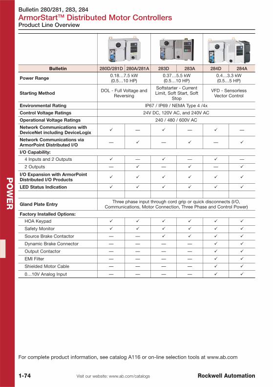
Bulletin 280/281, 283, 284
ArmorStartTM Distributed Motor Controllers
1-74 Visit our website: www.ab.com/catalogs Rockwell Automation
PO
WE
R
Product Line Overview
For complete product information, see catalog A116 or on-line selection tools at www.ab.com
Bulletin 280D/281D 280A/281A 283D 283A 284D 284A
Power Range 0.18…7.5 kW(0.5…10 HP)
0.37…5.5 kW(0.5…10 HP)
0.4…3.3 kW(0.5…5 HP)
Starting Method DOL - Full Voltage andReversing
Softstarter - CurrentLimit, Soft Start, Soft
Stop
VFD - SensorlessVector Control
Environmental Rating IP67 / IP69 / NEMA Type 4 /4x
Control Voltage Ratings 24V DC, 120V AC, and 240V AC
Operational Voltage Ratings 240 / 480 / 600V AC
Network Communications withDeviceNet including DeviceLogix � — � — � —
Network Communications viaArmorPoint Distributed I/O — � — � — �
I/O Capability:
4 Inputs and 2 Outputs � — � — � —
2 Outputs — � — � — �
I/O Expansion with ArmorPointDistributed I/O Products � � � � � �
LED Status Indication � � � � � �
Gland Plate Entry Three phase input through cord grip or quick disconnects (I/O,Communications, Motor Connection, Three Phase and Control Power)
Factory Installed Options:
HOA Keypad � � � � � �
Safety Monitor � � � � � �
Source Brake Contactor — — � � � �
Dynamic Brake Connector — — — — � �
Output Contactor — — — — � �
EMI Filter — — — — � �
Shielded Motor Cable — — — — � �
0…10V Analog Input — — — — � �

Bulletin 150Soft Starters
1-75Visit our website: www.ab.com/catalogsRockwell Automation
PO
WE
R
Bulletin 150-C 150-F
Type SMC-3 Controller SMC Flex Controller
Current Range 200…600V1…480 A / 831 A
200…600V / 690V �1…1250 A / 1600 A
Soft Start � �
Kickstart � �
Current Limit � �
Dual Ramp Start — ��
Full Voltage — �
Soft Stop � �
Pump Control — ��
Preset Slow Speed — ��
Linear Speed — ��
SMB™ Smart MotorBraking — ��
Accu-Stop™ — ��
Slow Speed with Braking — ��
Integrated Bypass Contacts � �
Integrated Motor Protection � �
Communication — �
Metering — �
Keypad Programming/LCD Display — �
Standards Compliance:CE Marked perLow Voltage Directive73/23/EEC, 93/68/EEC
� �
CSA Certified(File No. LR 1234), � �
UL Listed(File No. E96956) � �
Product Selection See page 1-76 See page 1-78
� Depending on selected option� for 108…1250 A types
Smart Motor Controllers
Product Line Overview

Bulletin 150Soft Starters
1-76 Visit our website: www.ab.com/catalogs Rockwell Automation
PO
WE
R
Smart Motor Controllers SMC-3
Product Selection
Up to 480V AC
� 1…480/831 A Range� Soft Start� Current Limit Start� Selectable Kick Start� Selectable Soft Stop� Built-In Overload Protection� Built-In SCR Bypass� For in-line or inside-the-delta configurations
Line Connection Delta Connection100…240V 50/60 Hz
Control24V AC/DC
ControlCurrent Rating
��Motor Power @
400V AC ‡Current Rating
��Motor Power @
400V AC ‡[A] [kW] [A] [kW] Cat. No. Cat. No.
1…3 1.1 1.7…5.1 0.55…2.2 150-C3NBD 150-C3NBR3…9 4 5.1…16 2.2…7.5 150-C9NBD 150-C9NBR
5.3…16 7.5 9.1…27.6 4…11 150-C16NBD 150-C16NBR6.3…19 7.5 10.9…32.8 4…15 150-C19NBD 150-C19NBR
9.2…27.7 11 14.3…43 5.5…22 150-C25NBD 150-C25NBR10…30 15 17.3…52 7.5…22 150-C30NBD 150-C30NBR
12.3…37 18.5 21…64 7.5…30 150-C37NBD 150-C37NBR14.3…43 22 25…74 11…37 150-C43NBD 150-C43NBR20…60 30 34.6…104 15…55 150-C60NBD 150-C60NBR
28.3…85 45 50…147 22…75 150-C85NBD 150-C85NBR27…108 55 47…187 90 150-C108NBD 150-C108NBR34…135 75 59…234 132 150-C135NBD 150-C135NBR67…201 95…110 116…348 160 150-C201NBD 150-C201NBR84…251 95…132 145…435 250 150-C251NBD 150-C251NBR106…317 95…160 183…549 315 150-C317NBD 150-C317NBR120…361 110…200 208…625 355 150-C361NBD 150-C361NBR160…480 160…250 277…831 450 150-C480NBD 150-C480NBR
Up to 600V ACLine Connection Delta Connection
100…240V 50/60 HzControl
24V AC/DCControl
Current Rating��
Motor Power @525V AC ‡
Current Rating��
Motor Power @525V AC ‡
[A] [kW] [A] [kW] Cat. No. Cat. No.1…3 1.5 1.7…5.1 0.75…3 150-C3NCD 150-C3NCR3…9 5.5 5.1…16 3…7.5 150-C9NCD 150-C9NCR
5.3…16 7.5 9.1…27.6 5.5…15 150-C16NCD 150-C16NCR6.3…19 11 10.9…32.8 5.5…22 150-C19NCD 150-C19NCR
9.2…27.7 15 14.3…43 7.5…22 150-C25NCD 150-C25NCR10…30 18.5 17.3…52 11…30 150-C30NCD 150-C30NCR
12.3…37 22 21…64 11…37 150-C37NCD 150-C37NCR14.3…43 22 25…74 15…45 150-C43NCD 150-C43NCR20…60 37 84.6…104 22…55 150-C60NCD 150-C60NCR
28.3…85 55 50…147 30…90 150-C85NCD 150-C85NCR27…108 75 47…187 132 150-C108NCD 150-C108NCR34…135 90 59…234 160 150-C135NCD 150-C135NCR67…201 75…132 116…348 250 150-C201NCD 150-C201NCR84…251 90…160 145…435 315 150-C251NCD 150-C251NCR106…317 100…200 183…549 400 150-C317NCD 150-C317NCR120…361 132…250 208…625 450 150-C361NCD 150-C361NCR160…480 200…315 277…831 560 150-C480NCD 150-C480NCR
� Motor FLA and motor running current must fall within the running current range of the device to operate properly.� From series letter "B", these units can be used in the inside the delta wiring with a current range 1.73 x higher.‡ Calculated using 350 % over current during starting.

Bulletin 150Soft Starters
1-77Visit our website: www.ab.com/catalogsRockwell Automation
PO
WE
R
Accessories
Accessories for SMC-3
Description N.O. N.C. Connection Diagram Cat. No.
Auxiliary Contact Blocks forside mounting withsequence terminaldesignations1- and 2-poleQuick and easy mountingwithout toolsOne block per device only
1 0 150-CA10
2 0 150-CA20
0 1 150-CA01
1 1 150-CA11
Description For Use With Cat. No.
FanField installed 150-C3…37 � 150-CF64
Connecting modules to 140-MElectrical interconnection between SMC-Delta/SMC-3 and 140-M.Motor protector and SMC must be mountedseparately.
Connects 140-M-C to150-C3…25 150-CC25
Connects 140-M-D to150-C3…25 150-CD25
Connects 140-M-F to150-C3…37 150-CF45
Connecting modules to 100-CElectrical interconnection between SMC-Delta/SMC-3 and 100-C.Contactor and SMC must be mountedseparately.
Connects 100-C09…23 to150-C3…19 150-CI23
Connects 100-C30…37 to150-C3…37 150-CI37
480V Protective Module150-C3…37NB 150-C84
150-C43…85NB (lineand/or load) 150-C84P
600V Protective Module150-C3…37NC 150-C86
150-C43…85NC (lineand/or load) 150-C86P
IEC Terminal Covers �
IEC line or load terminal covers for 108 and 135 A devices.Dead front protection 150-TC1
IEC line or load terminal covers for 201…251 A devices. Dead front protection 150-TC2
IEC line or load terminal covers for 317…480 A devices. Dead front protection 150-TC3
� For devices above this range, the fan is shipped with the device as standard.�One terminal cover is shipped as standard with the SMC-3 controllers from 108…480 A.

Bulletin 150Soft Starters
1-78 Visit our website: www.ab.com/catalogs Rockwell Automation
PO
WE
R
Product Selection
Smart Motor Controllers SMC-Flex
Up to 480V AC
� 1…1250/1600 A Range � Full Voltage� Soft Start � Linear Speed Acceleration� Current Limit Start � Preset Slow Speed� Dual Ramp � Soft Stop
Options� Pump Control� Braking Control
Line Connection��‡
Delta Connection��‡
100…240V AC 50/60 Hz Control §
WithoutOption
With PumpControl Option
Motor Current [A] 400V [kW] Motor Current [A] 400V [kW] Cat. No. Cat. No.
1…5 2.2 1.7…8.7 4 150-F5NBD 150-F5NBDB
5...25 11 8.7…43 22 150-F25NBD 150-F25NBDB
8.6...43 22 14.9…74 37 150-F43NBD 150-F43NBDB
12...60 30 20.8…104 55 150-F60NBD 150-F60NBDB
17...85 45 29.4…147 75 150-F85NBD 150-F85NBDB
27…108 55 47…187 90 150-F108NBD 150-F108NBDB
34…135 75 59…234 132 150-F135NBD 150-F135NBDB
67…201 110 116…348 160 150-F201NBD 150-F201NBDB
84…251 132 145…435 250 150-F251NBD 150-F251NBDB
106…317 160 183…549 315 150-F317NBD 150-F317NBDB
120…361 200 208…625 355 150-F361NBD 150-F361NBDB
160…480 250 277…831 450 150-F480NBD 150-F480NBDB
208…625 355 283…850 500 150-F625NBA 150-F625NBAB
260…780 450 300…900 500 150-F780NBA 150-F780NBAB
323…970 560 400…1200 710 150-F970NBA 150-F970NBAB
416…1250 710 533…1600 900 150-F1250NBA 150-F1250NBAB
� Controllers rated 108 A and greater are not equipped with line and load terminal lugs.�Motor FLA and motor running current must fall within the running current range of the device to operate properly.‡ Utilization category: 5…480 A: AC-53b: 3-50: 1750 / 625…1250 A: AC-53b: 3.0-50: 3550§ Reduced control voltage range for devices from 625…1250 A. See configuration table in
section "b" on page 1-78C.

Bulletin 150Soft Starters
1-78AVisit our website: www.ab.com/catalogsRockwell Automation
PO
WE
R
Product Selection
Line Connection��‡
Delta Connection��‡
100…240V AC 50/60 Hz Control §
WithoutOption
With PumpControl Option
Motor Current [A] 500V [kW] Motor Current [A] 500V [kW] Cat. No. Cat. No.
1...5 2.2 1.7…8.7 5.5 150-F5NCD 150-F5NCDB
5...25 15 8.7…43 15 150-F25NCD 150-F25NCDB
8.6...43 22 14.9…74 45 150-F43NCD 150-F43NCDB
12...60 37 20.8…104 55 150-F60NCD 150-F60NCDB
17...85 55 29.4…147 90 150-F85NCD 150-F85NCDB
27…108 75 47…187 132 150-F108NCD 150-F108NCDB
34…135 90 59…234 160 150-F135NCD 150-F135NCDB
67…201 132 116…348 250 150-F201NCD 150-F201NCDB
84…251 160 145…435 315 150-F251NCD 150-F251NCDB
106…317 200 183…549 400 150-F317NCD 150-F317NCDB
120…361 250 208…625 450 150-F361NCD 150-F361NCDB
160…480 315 277…831 560 150-F480NCD 150-F480NCDB
208…625 450 283…850 560 150-F625NCA 150-F625NCAB
260…780 560 300…900 630 150-F780NCA 150-F780NCAB
323…970 710 400…1200 800 150-F970NCA 150-F970NCAB
416…1250 900 533…1600 1100 150-F1250NCA 150-F1250NCAB
� Controllers rated 108 A and greater are not equipped with line and load terminal lugs.�Motor FLA and motor running current must fall within the running current range of the device to operate properly.‡ Utilization category: 5…480 A: AC-53b: 3-50: 1750 / 625…1250 A: AC-53b: 3.0-50: 3550§ Reduced control voltage range for devices from 625…1250 A. See configuration table in
section "b" on page 1-78C.
Up to 600V AC
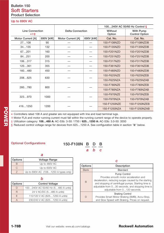
Bulletin 150Soft Starters
1-78B Visit our website: www.ab.com/catalogs Rockwell Automation
PO
WE
R
Optional Configurations 150-F108N B D B
a b ca
Options Voltage Range
B Up to 480V AC
C Up to 600V AC
Z Up to 690V AC (108…1250 A types only)
bOptions Control Voltage
D 100…240V AC 50/60 Hz (5…480 A units)
R 24 V AC/DC (5…480 A units)
E 110/120 V AC (625…1250 A units)
A 230/240 V AC (625…1250 A units)
cOptions Description
Blank SStandard
B
Pump ControlProvides smooth motor acceleration and
deceleration, reducing surges caused by the startingand stopping of centrifugal pumps. Starting time is
adjustable from 0…30 seconds, and stopping time isadjustable from 0…120 seconds.
DBraking Control
Provides Smart Motor Braking (SMB), Accu-Stop,and Slow Speed with Braking. Prices on request.
Product Selection
Up to 690V AC
Line Connection��‡
Delta Connection
100…240V AC 50/60 Hz Control §
WithoutOption
With PumpControl Option
Motor Current [A] 690V [kW] Motor Current [A] 690V [kW] Cat. No. Cat. No.
27…108 90 — — 150-F108NZD 150-F108NZDB
34…135 132 — — 150-F135NZD 150-F135NZDB
67…201 160 — — 150-F201NZD 150-F201NZDB
84…251 200 — — 150-F251NZD 150-F251NZDB
106…317 315 — — 150-F317NZD 150-F317NZDB
120…361 355 — — 150-F361NZD 150-F361NZDB
160…480 450 — — 150-F480NZD 150-F480NZDB
208…625 630 — —150-F625NZE 150-F625NZEB
150-F625NZA 150-F625NZAB
260…780 800 — —150-F780NZE 150-F780NZEB
150-F780NZA 150-F780NZAB
323…970 1000 — —150-F970NZE 150-F970NZEB
150-F970NZA 150-F970NZAB
416…1250 1200 — —150-F1250NZE 150-F1250NZEB
150-F1250NZA 150-F1250NZAB
� Controllers rated 108 A and greater are not equipped with line and load terminal lugs.�Motor FLA and motor running current must fall within the running current range of the device to operate properly.‡ Utilization category: 108…480 A: AC-53b: 3-50: 1750 / 625…1250 A: AC-53b: 3.0-50: 3550§ Reduced control voltage range for devices from 625…1250 A. See configuration table in section "b" below.

Bulletin 150Soft Starters
1-79Visit our website: www.ab.com/catalogsRockwell Automation
PO
WE
R
Accessories
Accessories for SMC-Flex
Description Cat. No.
Protective Modules �
480V Protective Module5…85 A 150-F84
108…1250 A 150-F84L
600V Protective Module5…85 A 150-F86
108…1250 A 150-F86L
IEC Terminal Covers �
IEC line or load terminal covers for 108 and 135 A devices.Dead front protection 150-TC1
IEC line or load terminal covers for 201…251 A devices. Dead front protection 150-TC2
IEC line or load terminal covers for 317…480 A devices. Dead front protection 150-TC3
Human Interface Modules
Hand HeldHuman Interface Modules
LCD Display, Full Numeric Keypad ‡ 20-HIM-A3
LCD Display, Programmer Only ‡ 20-HIM-A5
Door MountedHuman Interface Modules
Remote (Panel Mount) LCD Display, FullNumeric Keypad 20-HIM-C3S
Human Interface ModuleInterface Cables PowerFlex HIM Interface Cable, 1 m (39 in) 20-HIM-H10
Communication Modules
Communication Modules(IP30/Type 1)
Remote I/O Communication Adapter 20-COMM-R
RS485 DF1 Communication Adapter 20-COMM-S
PROFIBUS™ DP Communication Adapter 20-COMM-P
HVAC Communication Adapter 20-COMM-H
ControlNet™ Communication Adapter (Fiber) 20-COMM-Q
ControlNet™ Communication Adapter (Coax) 20-COMM-C
DeviceNet™ Communication Adapter 20-COMM-D
EtherNet/IP™ Communication Adapter 20-COMM-E
Core Balance Transformer
Core Balance GroundFault Sensor
100:1 825-CBCT
� The same protective module mounts on the line or load side of the SMC-Flex. For applications requiring both lineand load side protection, two protective modules must be ordered.
�One terminal cover is shipped as standard with the SMC-Flex controllers from 108…480 A.‡ Requires a 20-HIM-H10 cable to connect to the SMC-Flex.

PowerFlex 4, 4M, 40, 40P, 400, 70, 700Drives
1-80 Visit our website: www.ab.com/catalogs Rockwell Automation
PO
WE
R
Product Line Overview
PowerFlex 4, 4M, 40
Bulletin 22A… 22F… 22B… 22D… 22C…
Type PowerFlex 4 PowerFlex 4M PowerFlex 40 PowerFlex 40P PowerFlex 400
Ratings 240V,1-phase 0.25…2.2 kW 0.25…2.2 kW 0.37…2.2 kW N/A N/A
Ratings200…240V 0.25…4.0 kW 0.25…7.5 kW 0.37…7.5 kW 0.37…7.5 kW 2.2…37 kW
Ratings400…480V 0.37…4.0 kW 0.37…11 kW 0.37…11 kW 0.37…11 kW 2.2…250 kW
Ratings500…600V N/A N/A 0.75…11 kW 0.75…11 kW N/A
Ratings 690V N/A N/A N/A N/A N/A
AmbientTemperature
IP 20-10 °C to 50 °C
IP 20-10 °C to 50 °C
IP 20-10 °C to 50 °C
IP 20-10 °C to 50 °C
IP 200 °C to 50 °C
EMC FiltersInternal (1-phase)
External (3-phase)
Internal(1-phase and 3-
phase)
Internal (1-phase)External (3-
phase)
External (3-phase)
External (3-phase)
Standards UL, CE, CSA,C-Tick
UL, CE, CSA,C-Tick
UL, CE, CSA,C-Tick
UL, CE, CSA,C-Tick
UL, CE, CSA,C-Tick
CarrierFrequency 2…16 kHz 2…10 kHz 2…16 kHz 2…16 kHz 2…10 kHz
OverloadCapability
150% for 60 s200% for 3 s
150% for 60 s200% for 3 s
150% for 60 s200% for 3 s
150% for 60 s200% for 3 s 110% for 60 s
ControlPerformance
- Volts per Hertz- Slip
Compensation
- Volts per Hertz- Slip
Compensation
- Volts per Hertz- Slip
Compensation- Sensorless
Vector
- Volts per Hertz- Slip
Compensation- Sensorless
Vector- Speed controlwith or without
EncoderFeedback
- Volts per Hertz- Slip
Compensation
CommunicationsOptions
- Integral RS485- RTU Slave
- Integral RS485- RTU Slave
- Integral RS485- RTU Slave- DeviceNet- ControlNet - EtherNet- Profibus
- LonWorks- BACnet
- Integral RS485- RTU Slave- DeviceNet- ControlNet - EtherNet- Profibus
- LonWorks- BACnet
- Integral RS485- RTU Slave- DeviceNet- ControlNet - EtherNet- Profibus
- LonWorks- BACnet
ProductSelection
Page 1-82,1-96
Page 1-84,1-96
Page 1-86,1-96
Page 1-88,1-96
Page 1-90,1-96

PowerFlex 4, 4M, 40, 40P, 400, 70, 700 Drives
1-81Visit our website: www.ab.com/catalogsRockwell Automation
PO
WE
R
Product Line Overview
PowerFlex 70, 700
Bulletin 20A… 20B…
Type PowerFlex 70 PowerFlex 700
Ratings 240V, 1-phase N/A N/A
Ratings 200…240V 0.37…15 kW 0.37…55 kW
Ratings 400…480V 0.37…37 kW 0.37…132 kW
Ratings 500…600V 0.37…37 kW 0.37…110 kW
Ratings 690V N/A 45…132 kW
Ambient Temperature IP20 or IP660 °C to 50 °C
IP 200 °C to 50 °C
EMC Filters Internal Internal
Standards UL, CE, CSA,C-Tick
UL, CE, CSA,C-Tick
Carrier Frequency 2…12 kHz 2…10 kHz
Overload Capability
Normal Duty Application110% - 60 s150% - 3 s
Heavy Duty Application150% - 60 s200% - 3 s
Normal Duty Application110% - 60 s150% - 3 s
Heavy Duty Application150% - 60 s200% - 3 s
Control Performance
- Volts per Hertz- Slip Compensation- Sensorless Vector
- Field Oriented Control with or withoutEncoder for Speed Control and Torque
Regulation
- Volts per Hertz- Slip Compensation- Sensorless Vector
- Field Oriented Control with or withoutEncoder for Speed Control and Torque
Regulation
CommunicationsOptions
- DeviceNet- ControlNet- EtherNet
- Remote I/O- RS485 DF1
- Profibus- InterBus- CanOpen- LonWorks
- HVAC Modbus RTU- ModBus- Metasys- BACnet
- DeviceNet- ControlNet- EtherNet
- Remote I/O- RS485 DF1
- Profibus- InterBus- CanOpen- LonWorks
- HVAC Modbus RTU- ModBus- Metasys- BACnet
Product Selection Page 1-92, 1-96 Page 1-94, 1-96

PowerFlex 4Drives
1-82 Visit our website: www.ab.com/catalogs Rockwell Automation
PO
WE
R
Product Selection
PowerFlex 4 AC Drive
� 0.25…2.2 kW @ 240V 1-phase0.25…4 kW @ 400V 3-phase(240V and 480V 3-phase also available)
� V/Hz control� Versions with and without integral dynamic brake chopper� Integral RS 485 communication: allows multi-drop configurations
(up to 4 additional PowerFlex 4 Class drives on one network node)� Integral programming keypad and local LED status indication� Programmable via DriveExplorer or DriveExecutive (1203-USB required)� Zero-stacking (no spacing required between drives)
Typical MotorRating
Input Voltage
Drive Output[A] Frame
Size
Dimensions
Cat. No.[kW] [A] Cont. 60 s 3 s H x W x D
0.2 1.3
200…240V 50/60Hz,1-phase, EMC Filter,no Brake Chopper
1.4 2.1 2.8 A 152x80x136 22A-A1P4N113
0.4 1.9 2.1 3.2 4.2 A 152x80x136 22A-A2P1N113
0.75 3.3 3.6 5.4 7.2 A 152x80x136 22A-A3P6N113
1.5 6.1 6.8 10.2 13.6 B 180x100x136 22A-A6P8N113
2.2 8.9 9.6 14.4 19.2 B 180x100x136 22A-A9P6N113
0.2 1.3
200…240V 50/60Hz,1-phase,
no EMC Filter,no Brake Chopper
1.4 2.1 2.8 A 152x80x136 22A-A1P4N103
0.4 1.9 2.1 3.2 4.2 A 152x80x136 22A-A2P1N103
0.75 3.3 3.6 5.4 7.2 A 152x80x136 22A-A3P6N103
1.5 6.1 6.8 10.2 13.6 B 180x100x136 22A-A6P8N103
2.2 8.9 9.6 14.4 19.2 B 180x100x136 22A-A9P6N103
0.2 1.3200…240V 50/60Hz,1-phase, EMC Filter,
Brake Chopper
1.5 2.3 3 A 152x80x136 22A-A1P5N114
0.4 1.9 2.3 3.5 4.6 A 152x80x136 22A-A2P3N114
0.75 3.3 4.5 6.8 9 A 152x80x136 22A-A4P5N114
1.5 6.1 8 12 16 B 180x100x136 22A-A8P0N114
0.2 1.3200…240V 50/60Hz,
3-phase,no EMC Filter,Brake Chopper
1.5 2.3 3 A 152x80x136 22A-A1P5N104
0.4 1.9 2.3 3.5 4.6 A 152x80x136 22A-A2P3N104
0.75 3.3 4.5 6.8 9 A 152x80x136 22A-A4P5N104
1.5 6.1 8 12 16 B 180x100x136 22A-A8P0N104
0.2 1.3
200…240V 50/60Hz,3-phase,
no EMC Filter,Brake Chopper
1.5 2.3 3 A 152x80x136 22A-B1P5N104
0.4 1.9 2.3 3.5 4.6 A 152x80x136 22A-B2P3N104
0.75 3.3 4.5 6.8 9 A 152x80x136 22A-B4P5N104
1.5 6.1 8 12 16 A 152x80x136 22A-B8P0N104
2.2 8.9 12 18 24 B 180x100x136 22A-B012N104
3.7 15.3 17.5 25.5 34 B 180x100x136 22A-B017N104
0.4 1.1
400…480V 50/60Hz,3-phase,
no EMC Filter,Brake Chopper
1.4 2.1 2.8 A 152x80x136 22A-D1P4N104
0.75 1.9 2.3 3.5 4.6 A 152x80x136 22A-D2P3N104
1.5 3.5 4 6 8 A 152x80x136 22A-D4P0N104
2.2 5 6 9 12 B 180x100x136 22A-D6P0N104
3.7 8.4 8.7 13.1 17.4 B 180x100x136 22A-D8P7N104
See Publication 22-TD001… for complete product information.

PowerFlex 4 Drives
1-83Visit our website: www.ab.com/catalogsRockwell Automation
PO
WE
R
Product Selection
PowerFlex 4 Options
Cat. No.
External EMC Filter for up to 10 m of Motor Cable
EMC Filter PowerFlex 4, 200…240V, 3-phase, 9.5 A, Frame A 22-RF9P5-AS
EMC Filter PowerFlex 4/40, 200…240V, 3-phase, 21 A, Frame B 22-RF021-BS
EMC Filter PowerFlex 4, 400…480V, 3-phase, 5.7 A, Frame A 22-RF5P7-AS
EMC Filter PowerFlex 4/40, 400…480V, 3-phase, 12 A, Frame B 22-RF012-BS
External EMC Filter for up to 10 m of Motor Cable, Low Leakage Current
EMC Filter PowerFlex 4, 230V, 1-phase, 18 A, Frame B, Low Leakage 22-RFL018-BS
EMC Filter PowerFlex 4, 230V, 1-phase, 10 A, Frame A, Low Leakage 22-RFL010-AS
EMC Filter PowerFlex 4, 230V, 3-phase, 21 A, Frame B, Low Leakage 22-RFL021-BS
EMC Filter PowerFlex 4, 400V, 3-phase, 12 A, Frame B, Low Leakage 22-RFL012-BS
EMC Filter PowerFlex 4, 230/400V, 3-phase, 9.5 A, Frame A, Low Leakage 22-RFL9P5-AS
External EMC Filter for >10 m up to 100 m of Motor Cable
EMC Filter PowerFlex 4, 200…240V, 1-phase, 10 A, Frame A 22-RF010-AL
EMC Filter PowerFlex 4/40, 200…240V, 1-phase, 18 A, Frame B 22-RF018-BL
EMC Filter PowerFlex 4, 200…240V, 3-phase, 9.5 A, Frame A 22-RF9P5-AL
EMC Filter PowerFlex 4/40, 200…240V, 3-phase, 21 A, Frame B 22-RF021-BL
EMC Filter PowerFlex 4, 400…480V, 3-phase, 5.7 A, Frame A 22-RF5P7-AL
EMC Filter PowerFlex 4/40, 400…480V, 3-phase, 12 A, Frame B 22-RF012-BL
External User Interface Modules
Panel Mount, IP66, Full Numeric LCD, Cable 2 m 22-HIM-C2S
Hand Held, IP30, Full Numeric LCD, Cable 1 m 22-HIM-A3
Bezel Kit, IP20 for use with 22-HIM-A3 22-HIM-B1
DSI HIM Cable, 1 m 22-HIM-H10
DSI HIM Cable, 2.9 m 22-HIM-H30
Communication Options
Built in RS485 (standard) —
Compact Logix to DSI AK-U0-RJ45-SC1
RJ45 One Port to Two Ports Splitter 1769-SM2
RJ45 120 Ohm Terminating Resistors (2 pcs) AK-U0-RJ45-TR1
Communication Option, RJ45 Dual Position Terminal Block (5 pcs) AK-U0-RJ45-TB2P
PC Programming Tool
USB to DSI/DPI Converter with Software DriveExplorer Light Version 1203-USB
Serial Converter Module with Software DriveExplorer Light Version 22-SCM-232
Programming Software
DriveExplorer, Full version 9306-4EXP02ENE
DriveTools SP Suite, DriveExecutive and DriveObserver 9303-4DTS01ENE
See Publication 22-TD001… for complete product information.

PowerFlex 4MDrives
1-84 Visit our website: www.ab.com/catalogs Rockwell Automation
PO
WE
R
PowerFlex 4M AC Drive
Product Selection
PowerFlex 4M 200-240V
PowerFlex 4M 400-480V
� 0.25 kW…2.2 kW @ 240V 1-phase0.25…11 kW @ 400V 3-phase(240V and 480V 3-phase also available)
� V/Hz control� Small physical size with feed-through wiring and in-built EMC filter� Integral RS 485 communication: allows multi-drop configurations
(up to 4 additional PowerFlex 4 Class drives on one network node)� Integral programming keypad and local LED status indication� Programmable via DriveExplorer or DriveExecutive (1203-USB required)� Zero-Stacking (no spacing required between drives)
Typical MotorRating
Input Voltage
Drive Output (HD)[A] Frame
Size
Dimensions
Cat. No.[kW] [A] Cont. 60 s 3 s H x W x D
0.2 1.3
200…240V 50/60Hz,1-phase, EMC Filter,no Brake Chopper
1.6 2.4 3.2 A 174x72x136 22F-A1P6N113
0.4 1.9 2.5 3.8 5 A 174x72x136 22F-A2P5N113
0.75 3.3 4.2 6.3 8.4 A 174x72x136 22F-A4P2N113
1.5 6.1 8 12 16 B 174x100x136 22F-A8P0N113
2.2 8.9 11 16.5 22 B 174x100x136 22F-A011N113
0.2 1.3
200…240V 50/60Hz,1-phase,
no EMC Filter,no Brake Chopper
1.6 2.4 3.2 A 174x72x136 22F-A1P6N103
0.4 1.9 2.5 3.8 5 A 174x72x136 22F-A2P5N103
0.75 3.3 4.2 6.3 8.4 A 174x72x136 22F-A4P2N103
1.5 6.1 8 12 16 B 174x100x136 22F-A8P0N103
2.2 8.9 11 16.5 22 B 174x100x136 22F-A011N103
0.2 1.3
200…240V 50/60Hz,3-phase,
no EMC Filter,no Brake Chopper(…104 with Brake
Chopper)
1.6 2.4 3.2 A 174x72x136 22F-B1P6N103
0.4 1.9 2.5 3.8 5 A 174x72x136 22F-B2P5N103
0.75 3.3 4.2 6.3 8.4 A 174x72x136 22F-B4P2N103
1.5 6.1 8 12 16 A 174x72x136 22F-B8P0N103
2.2 8.9 12 18 24 B 174x100x136 22F-B012N103
3.7 15.3 17.5 25.5 34 B 174x100x136 22F-B017N103
5.5 21 25 37.5 50 C 260x130x180 22F-B025N104
7.5 28 33 49.5 66 C 260x130x180 22F-B033N104
Typical MotorRating
Input Voltage
Drive Output (HD)[A] Frame
Size
Dimensions
Cat. No.[kW] [A] Cont. 60 s 3 s H x W x D
0.4 1.1
400…480V 50/60Hz,3-phase, EMC Filter,no Brake Chopper(…114 with Brake
Chopper)
1.5 2.1 2.8 A 174x72x136 22F-D1P5N113
0.75 1.9 2.5 3.8 5 A 174x72x136 22F-D2P5N113
1.5 3.5 4.2 6.3 8.4 A 174x72x136 22F-D4P2N113
2.2 5 6 9 12 B 174x100x136 22F-D6P0N113
3.7 8.4 8.7 13.1 17.4 B 174x100x136 22F-D8P7N113
5.5 11.4 13 19.5 26 C 260x130x180 22F-D013N114
7.5 15 18 27 36 C 260x130x180 22F-D018N114
11 22 24 36 48 C 260x130x180 22F-D024N114

PowerFlex 4M Drives
1-85Visit our website: www.ab.com/catalogsRockwell Automation
PO
WE
R
Product Selection
PowerFlex 4M Options
PowerFlex 4M 400-480V, continued
Typical MotorRating
Input Voltage
Drive Output (HD)[A] Frame
Size
Dimensions
Cat. No.[kW] [A] Cont. 60 s 3 s H x W x D
0.4 1.1
400…480V 50/60Hz,3-phase,
no EMC Filter,no Brake Chopper(…104 with Brake
Chopper)
1.5 2.1 2.8 A 174x72x136 22F-D1P5N103
0.75 1.9 2.5 3.8 5 A 174x72x136 22F-D2P5N103
1.5 3.5 4.2 6.3 8.4 A 174x72x136 22F-D4P2N103
2.2 5 6 9 12 B 174x100x136 22F-D6P0N103
3.7 8.4 8.7 13.1 17.4 B 174x100x136 22F-D8P7N103
5.5 11.4 13 19.5 26 C 260x130x180 22F-D013N104
7.5 15 18 27 36 C 260x130x180 22F-D018N104
11 22 24 36 48 C 260x130x180 22F-D024N104
Cat. No.
External EMC Filter for up to 100 m motor cable lenght
240V, 50/60 Hz, 1-phase, Frame A, 10 A 22F-RF010-AL
240V, 50/60 Hz, 1-phase, Frame B, 18 A 22F-RF025-BL
240V, 50/60 Hz, 3-phase, Frame A, 9.5 A 22F-RF9P5-AL
240V, 50/60 Hz, 3-phase, Frame B, 21 A 22F-RF021-BL
240V, 50/60 Hz, 3-phase, Frame C, 39 A 22F-RF039-CL
480V, 50/60 Hz, 3-phase, Frame A, 6 A 22F-RF6P0-AL
480V, 50/60 Hz, 3-phase, Frame B, 12 A 22F-RF012-BL
480V, 50/60 Hz, 3-phase, Frame C, 26 A 22F-RF026-CL
External User Interface Modules
Panel Mount, IP66, Full Numeric LCD, Cable 2 m 22-HIM-C2S
Hand Held, IP30, Full Numeric LCD, Cable 1 m 22-HIM-A3
Bezel Kit, IP20 for use with 22-HIM-A3 22-HIM-B1
DSI HIM Cable, 1 m 22-HIM-H10
DSI HIM Cable, 2.9 m 22-HIM-H30
Communication Options
Built in RS485 (standard) —
Compact Logix to DSI AK-U0-RJ45-SC1
RJ45 One Port to Two Ports Splitter 1769-SM2
RJ45 120 Ohm Terminating Resistors (2 pcs) AK-U0-RJ45-TR1
Communication Option, RJ45 Dual Position Terminal Block (5 pcs) AK-U0-RJ45-TB2P
PC Programming Tool
USB to DSI/DPI Converter with Software DriveExplorer Light Version 1203-USB
Serial Converter Module with Software DriveExplorer Light Version 22-SCM-232
Programming Software
DriveExplorer, Full version 9306-4EXP02ENE
DriveTools SP Suite, DriveExecutive and DriveObserver 9303-4DTS01ENE
See Publication 22F-TD001… for complete product information.

PowerFlex 40Drives
1-86 Visit our website: www.ab.com/catalogs Rockwell Automation
PO
WE
R
PowerFlex 40 AC Drive
Product Selection
� 0.37…2.2 kW @ 240V 1-phase0.37…11 kW @ 400…600V 3-phase(240V 3-phase also available)
� V/Hz and Sensorless Vector control� Integral dynamic brake chopper� Communication modules for industrial automation networks� Integral RS 485 communication: allows multi-drop configurations
(up to 4 additional PowerFlex 4 Class drives on one network node)� Integral programming keypad and local LED status indication� StepLogic with AND/OR and timer/counter functions� Programmable via DriveExplorer or DriveExecutive
(1203-USB required)� Zero stacking (no spacing required between drives)
Typical MotorRating
Input Voltage
Drive Output[A] Frame
Size
Dimensions
Cat. No.[kW] [A] Cont. 60 s 3 s H x W x D
0.4 1.9200…240V 50/60Hz,1-phase, EMC Filter,
Brake Chopper
2.3 3.5 4.6 B 180x100x136 22B-A2P3N114
0.75 3.3 5 7.5 10 B 180x100x136 22B-A5P0N114
1.5 6.1 8 12 16 B 180x100x136 22B-A8P0N114
2.2 8.9 12 18 24 C 260x130x180 22B-A012N114
0.4 1.9 200…240V 50/60Hz,1-phase,
no EMC Filter,Brake Chopper
2.3 3.5 4.6 B 180x100x136 22B-A2P3N104
0.75 3.3 5 7.5 10 B 180x100x136 22B-A5P0N104
1.5 6.1 8 12 16 B 180x100x136 22B-A8P0N104
2.2 8.9 12 18 24 C 260x130x180 22B-A012N104
0.4 1.9
200…240V 50/60Hz,3-phase,
no EMC Filter,Brake Chopper
2.3 3.5 4.6 B 180x100x136 22B-B2P3N104
0.75 3.3 5 7.5 10 B 180x100x136 22B-B5P0N104
1.5 6.1 8 12 16 B 180x100x136 22B-B8P0N104
2.2 8.9 12 18 24 B 180x100x136 22B-B012N104
3.7 15.3 17.5 25.5 34 B 180x100x136 22B-B017N104
5.5 21 24 36 48 C 260x130x180 22B-B024N104
7.5 28 33 49.5 66 C 260x130x180 22B-B033N104
0.4 1.1
400…480V 50/60Hz,3-phase,
no EMC Filter,Brake Chopper
1.4 2.1 2.8 B 180x100x136 22B-D1P4N104
0.75 1.9 2.3 3.5 4.6 B 180x100x136 22B-D2P3N104
1.5 3.5 4 6 8 B 180x100x136 22B-D4P0N104
2.2 5 6 9 12 B 180x100x136 22B-D6P0N104
4 8.4 10.5 15 20 B 180x100x136 22B-D010N104
5.5 11.4 12 18 24 C 260x130x180 22B-D012N104
7.5 15 17 25.5 34 C 260x130x180 22B-D017N104
11 22 24 36 48 C 260x130x180 22B-D024N104
0.75 —
600V 50/60Hz,3-phase,
no EMC Filter,Brake Chopper
1.7 2.5 3.4 B 180x100x136 22B-E1P7N104
1.5 — 3 4.5 6 B 180x100x136 22B-E3P0N104
2.2 — 4.2 6.3 8.4 B 180x100x136 22B-E4P2N104
4 — 6.6 9.9 13.2 B 180x100x136 22B-E6P6N104
5.5 — 9.9 14.8 19.8 C 260x130x180 22B-E9P9N104
7.5 — 12 18 24 C 260x130x180 22B-E012N104
11 — 19 28 38 C 260x130x180 22B-E019N104
See Publication 22-TD001… for complete product information.

PowerFlex 40 Drives
1-87Visit our website: www.ab.com/catalogsRockwell Automation
PO
WE
R
Product Selection
Options
Cat. No.
External EMC Filter for up to 10 m of Motor Cable
EMC Filter PowerFlex 4/40, 200…240V, 3-phase, 21 A, Frame B 22-RF021-BSEMC Filter PowerFlex 40, 200…240V, 3-phase, 34 A, Frame C 22-RF034-CS
EMC Filter PowerFlex 4/40, 400…480V, 3-phase, 12 A, Frame B 22-RF012-BSEMC Filter PowerFlex 40, 400…480V, 3-phase, 18 A, Frame C 22-RF018-CSEMC Filter PowerFlex 40/400, 480V, 3-phase, 26 A, Frame C 22-RF026-CS
External EMC Filter for up to 100 m of Motor CableEMC Filter PowerFlex 4/40, 200…240V, 1-phase, 18 A, Frame B 22-RF018-BLEMC Filter PowerFlex 40, 200…240V, 1-phase, 25 A, Frame C 22-RF025-CL
EMC Filter PowerFlex 4/40, 200…240V, 3-phase, 21 A, Frame B 22-RF021-BL
EMC Filter PowerFlex 40, 200…240V, 3-phase, 34 A, Frame C 22-RF034-CL
EMC Filter PowerFlex 4/40, 400…480V, 3-phase, 12 A, Frame B 22-RF012-BLEMC Filter PowerFlex 40, 400…480V, 3-phase, 18 A, Frame C 22-RF018-CLEMC Filter PowerFlex 40, 480V, 3-phase, 26 A, Frame C 22-RF026-CLEMC Filter PowerFlex 40, 600V, 3-phase, 8 A, Long Motor Cable 22-RF8P0-BL
EMC Filter PowerFlex 40, 600V, 3-phase, 15 A, Long Motor Cable 22-RF015-CL
EMC Filter PowerFlex 40, 600V, 3-phase, 24 A, Long Motor Cable 22-RF024-CL
External User Interface ModulesPanel Mount, IP66, Full Numeric LCD, Cable 2 m 22-HIM-C2SHand Held, IP30, Full Numeric LCD, Cable 1 m 22-HIM-A3Bezel Kit, IP20 for use with 22-HIM-A3 22-HIM-B1DSI HIM Cable, 1 m 22-HIM-H10
DSI HIM Cable, 2.9 m 22-HIM-H30
Wireless Interface Module Bluetooth DSI, IP20 22-WIM-N1
Wireless Interface Module Bluetooth DSI, IP66 22-WIM-N4S
Communication OptionsBuilt in RS485 (standard) —
RJ45 One Port to Two Ports Splitter AK-U0-RJ45-SC1
RJ45 120 Ohm Terminating Resistors (2 pcs) AK-U0-RJ45-TR1
Communication Option, RJ45 Dual Position Terminal Block (5 pcs) AK-U0-RJ45-TB2PCommunication Module, DeviceNet (Frame B or C cover is needed) 22-COMM-DCommunication Module, ControlNet™ (Frame B or C cover is needed) 22-COMM-CCommunication Module, Profibus™ (Frame B or C cover is needed) 22-COMM-PCommunication Module, EtherNet/IP (Frame B or C cover is needed) 22-COMM-ECommunication Module, LonWorks (Frame B or C cover is needed) 22-COMM-L
Communication Module, BACnet (Frame B or C cover is needed) 22-COMM-B
Compact Logix to DSI Interface 1769-SM2Cover for Frame B PowerFlex 40 22B-CCBCover for Frame C PowerFlex 40 22B-CCC
PC Programming ToolSerial Converter Module with Software DriveExplorer Light Version 22-SCM-232USB to DSI/DPI Converter with Software DriveExplorer Light Version 1203-USB
Programming SoftwareDriveExplorer for PC 9306-4EXP02ENEDriveTools SP Suite, DriveExecutive and DriveObserver 9303-4DTS01ENE
See Publication 22-TD001… for complete product information.

PowerFlex 40PDrives
1-88 Visit our website: www.ab.com/catalogs Rockwell Automation
PO
WE
R
PowerFlex 40P AC Drive
Product Selection
� 0.37…11 kW @ 400…600V 3-phase(240V 3-phase also available)
� V/Hz and Sensorless Vector control� Integral dynamic brake chopper� Communication modules for industrial automation networks� Integral RS 485 communication: allows multi-drop configurations
(up to 4 additional PowerFlex 4 Class drives on one network node)� Speed control with and without encoder feedback� StepLogic with AND/OR and timer/counter functions� Safe-off option confirming to EN 954-1 Cat. 3� Specific features for fibre applications� Programmable via DriveExplorer or DriveExecutive
(1203-USB required)� Zero stacking (no spacing required between drives)
Typical MotorRating
Input Voltage
Drive Output [A] FrameSize
Dimensions
Cat. No.[kW] [A] Cont. 60 s 3 s H x W x D
0.4 1.9
200…240V 50/60Hz,3-phase,
no EMC Filter,Brake Chopper
2.3 3.5 4.6 B 180x100x136 22D-B2P3N104
0.75 3.3 5 7.5 10 B 180x100x136 22D-B5P0N104
1.5 6.1 8 12 16 B 180x100x136 22D-B8P0N104
2.2 8.9 12 18 24 B 180x100x136 22D-B012N104
3.7 15.3 17.5 25.5 34 B 180x100x136 22D-B017N104
5.5 21 24 36 48 C 260x130x180 22D-B024N104
7.5 28 33 49.5 66 C 260x130x180 22D-B033N104
0.4 1.1
400…480V 50/60Hz,3-phase,
no EMC Filter,Brake Chopper
1.4 2.1 2.8 B 180x100x136 22D-D1P4N104
0.75 1.9 2.3 3.5 4.6 B 180x100x136 22D-D2P3N104
1.5 3.5 4 6 8 B 180x100x136 22D-D4P0N104
2.2 5 6 9 12 B 180x100x136 22D-D6P0N104
4 8.4 10.5 15 20 B 180x100x136 22D-D010N104
5.5 11.4 12 18 24 C 260x130x180 22D-D012N104
7.5 15 17 25.5 34 C 260x130x180 22D-D017N104
11 22 24 36 48 C 180x100x136 22D-D024N104
0.75 -
600V 50/60Hz,3-Phase,
no EMX Filter,Brake Chopper
1.7 2.5 3.4 B 180x100x136 22D-E1P7N104
1.5 - 3 4.5 6 B 180x100x136 22D-E3P0N104
2.2 - 4.2 6.3 8.4 B 180x100x136 22D-E4P2N104
4.0 - 6.6 9.9 13.2 B 260x130x180 22D-E6P6N104
5.5 - 9.9 14.8 19.8 C 260x130x180 22D-E9P9N104
7.5 - 12 18 24 C 260x130x180 22D-E012N104
11 - 19 28 38 C 260x130x180 22D-E019N104
See Publication 22D-TD001… for complete product information.

PowerFlex 40P Drives
1-89Visit our website: www.ab.com/catalogsRockwell Automation
PO
WE
R
Product Selection
Options
Cat. No.
External EMC Filter for up to 10 m of Motor Cable
EMC Filter PowerFlex 4/40, 200…240V, 3-phase, 21 A, Frame B 22-RF021-BSEMC Filter PowerFlex 40, 200…240V, 3-phase, 34 A, Frame C 22-RF034-CSEMC Filter PowerFlex 4/40, 400…480V, 3-phase, 12 A, Frame B 22-RF012-BSEMC Filter PowerFlex 40, 400…480V, 3-phase, 18 A, Frame C 22-RF018-CSEMC Filter PowerFlex 40/400, 480V, 3-phase, 26 A, Frame C 22-RF026-CS
External EMC Filter for up to 100 m of Motor CableEMC Filter PowerFlex 4/40, 200…240V, 1-phase, 18 A, Frame B 22-RF018-BLEMC Filter PowerFlex 40, 200…240V, 1-phase, 25 A, Frame C 22-RF025-CLEMC Filter PowerFlex 4/40, 200…240V, 3-phase, 21 A, Frame B 22-RF021-BLEMC Filter PowerFlex 40, 200…240V, 3-phase, 34 A, Frame C 22-RF034-CLEMC Filter PowerFlex 4/40, 400…480V, 3-phase, 12 A, Frame B 22-RF012-BLEMC Filter PowerFlex 40, 400…480V, 3-phase, 18 A, Frame C 22-RF018-CLEMC Filter PowerFlex 40, 480V, 3-phase, 26 A, Frame C 22-RF026-CLEMC Filter PowerFlex 40, 600V, 3-phase, 8 A, Long Motor Cable 22-RF8P0-BLEMC Filter PowerFlex 40, 600V, 3-phase, 15 A, Long Motor Cable 22-RF015-CLEMC Filter PowerFlex 40, 600V, 3-phase, 24 A, Long Motor Cable 22-RF024-CL
External User Interface ModulesPanel Mount, IP66, Full Numeric LCD, Cable 2 m 22-HIM-C2SHand Held, IP30, Full Numeric LCD, Cable 1 m 22-HIM-A3Bezel Kit, IP20 for use with 22-HIM-A3 22-HIM-B1DSI HIM Cable, 1 m 22-HIM-H10DSI HIM Cable, 2.9 m 22-HIM-H30Wireless Interface Module Bluetooth DSI, IP20 22-WIM-N1Wireless Interface Module Bluetooth DSI, IP66 22-WIM-N4S
Communication OptionsBuilt in RS485 (standard) —RJ45 One Port to Two Ports Splitter AK-U0-RJ45-SC1RJ45 120 Ohm Terminating Resistors (2 pcs) AK-U0-RJ45-TR1Communication Option, RJ45 Dual Position Terminal Block (5 pcs) AK-U0-RJ45-TB2PCommunication Module, DeviceNet (Frame B or C cover is needed) 22-COMM-DCommunication Module, ControlNet (Frame B or C cover is needed) 22-COMM-CCommunication Module, Profibus (Frame B or C cover is needed) 22-COMM-PCommunication Module, EtherNet/IP (Frame B or C cover is needed) 22-COMM-ECommunication Module, LonWorks (Frame B or C cover is needed) 22-COMM-LCommunication Module, BACnet (Frame B or C cover is needed) 22-COMM-BCompact Logix to DSI Interface 1769-SM2Cover for Frame B PowerFlex 40 22B-CCBCover for Frame C PowerFlex 40 22B-CCC
PC Programming ToolSerial Converter Module with Software DriveExplorer Light Version 22-SCM-232USB to DSI/DPI Converter with Software DriveExplorer Light Version 1203-USB
Programming SoftwareDriveExplorer for PC 9306-4EXP02ENEDriveTools SP Suite -includes DriveExecutive, DriveObserver 9303-4DTS01ENE
Safe-Off OptionDriveGuard® Safe-Off Board 20A-DG01
See Publication 22D-TD001… for complete product information.

PowerFlex 400Drives
1-90 Visit our website: www.ab.com/catalogs Rockwell Automation
PO
WE
R
PowerFlex 400 AC Drive
Product Selection
� 0.37…250 kW @ 400V 3-phase(240V and 480V 3-phase also available)
� V/Hz control� For industrial pump and fan applications� Communication modules for industrial automation networks� Integral RS 485 communication: allows multi-drop configurations
(up to 4 additional PowerFlex 4 Class drives on one network node)� Integral programming keypad and local LED status indication� Programmable via DriveExplorer or DriveExecutive
(1203-USB required)� Zero stacking (no spacing required between drives)
Typical MotorRating
Input Voltage
Drive Output[A] Frame
Size
Dimensions
Cat. No.[kW] [A] Cont. 60 s H x W x D
2.2 9
200…240V 50/60Hz3-phase
12 13.2 C 260x130x180 22C-B012N103
3.7 16 17.5 19.25 C 260x130x180 22C-B017N103
5.5 21 24 26.4 C 260x130x180 22C-B024N103
7.5 28 33 36.3 C 260x130x180 22C-B033N103
11 40 49 54 D 384x250x205.4 22C-B049A103
15 52 65 71 D 384x250x205.4 22C-B065A103
18.5 61 75 82 D 384x250x205.4 22C-B075A103
22 72 90 99 D 384x250x205.4 22C-B090A103
30 95 120 132 E 589x370x260 22C-B120A103
37 117 145 159 E 589x370x260 22C-B145A103
2.2 5
400…480V 50/60Hz3-phase
6 6.6 C 260x130x180 22C-D6P0N103
4 8.4 10.5 11.5 C 260x130x180 22C-D010N103
5.5 11.4 12 13.2 C 260x130x180 22C-D012N103
7.5 15 17 18.7 C 260x130x180 22C-D017N103
11 22 22 24 C 260x130x180 22C-D022N103
15 29 30 33 C 260x130x180 22C-D030N103
18.5 34 38 42 D 384x250x205.4 22C-D038A103
22 40 45.5 50 D 384x250x205.4 22C-D045A103
30 53 60 66 D 384x250x205.4 22C-D060A103
37 65 72 79 E 589x370x260 22C-D072A103
45 78 88 96 E 589x370x260 22C-D088A103
55 98 105 115 E 589x370x260 22C-D105A103
75 132 142 156 E 589x370x260 22C-D142A103
90 158 170 187 F 850x425x280 22C-D170A103
110 194 208 228 F 850x425x280 22C-D208A103
132 235 260 286 G 892x425x264 22C-D260A103
160 276 310 341 G 892x425x264 22C-D310A103
200 345 370 407 H 1364x529x359 22C-D370A103
250 440 460 506 H 1364x529x359 22C-D460A103
See Publication 22C-TD001… for complete product information.

PowerFlex 400 Drives
1-91Visit our website: www.ab.com/catalogsRockwell Automation
PO
WE
R
Product Selection
Options
Cat. No.
Conversion Kit
Converts IP20 drive to IP30, NEMA/UL Type 1 enclosure. Includes conduit box, mountingscrews and plastic top panel. 22-JBAC
Converts IP20 drive to IP30, NEMA/UL Type 1 enclosure. Includes communication optionconduit box, mounting screws and plastic top panel. 22-JBCC
RFI FiltersEMC Filter 22-RF018-CSEMC Filter 22-RF026-CSEMC Filter 22-RFD036EMC Filter 22-RFD050EMC Filter 22-RFD070EMC Filter 22-RFD100EMC Filter 22-RFD150EMC Filter 22-RFD180EMC Filter 22-RFD208EMC Filter 22-RFD323EMC Filter 22-RFD480
External User Interface ModulesRemote (Panel Mount) LCD Display, Digital Speed Control, CopyCat Capable. 22-HIM-C2SHand Held, IP30, Full Numeric LCD, Cable 1 m 22-HIM-A3Bezel Kit, IP20 for use with 22-HIM-A3 22-HIM-B1DSI HIM Cable, 1 m 22-HIM-H10DSI HIM Cable, 2.9 m 22-HIM-H30Wireless Interface Module Bluetooth DSI, IP20 22-WIM-N1Wireless Interface Module Bluetooth DSI, IP20 22-WIM-N4S
Communication OptionsBuilt in RS458 (Standard) —RJ45 One Port to Two Ports Splitter AK-U0-RJ45-SC1RJ45 120 Ohm Terminating Resistors (2 pcs) AK-U0-RJ45-TR1Communication Option, RJ45 Dual Position Terminal Block (5 pcs) AK-U0-RJ45-TB2PCommunication Module, DeviceNet (Frame B or C cover is needed) 22-COMM-DCommunication Module, ControlNet (Frame B or C cover is needed) 22-COMM-CCommunication Module, Profibus (Frame B or C cover is needed) 22-COMM-PCommunication Module, EtherNet/IP (Frame B or C cover is needed) 22-COMM-ECommunication Module, LonWorks (Frame B or C cover is needed) 22-COMM-LCommunication Module, BACnet (Frame B or C cover is needed) 22-COMM-BCompact I/O Module (3 Channel) 1769-SM2Frame C Drive 22C-CCC
PC Programming ToolUSB to DSI/DPI Converter with Software DriveExplorer Light Version 1203-USBSerial Converter Module with Software DriveExplorer Light Version 22-SCM-232
Programming SoftwareDriveExplorer for PC 9306-4EXP02ENEDriveTools SP Suite -includes DriveExecutive, DriveObserver 9303-4DTS01ENE
Other Options
Auxiliary Relay Board - Expands drive output capabilities - Frames D-H only. AK-U9-RLB1
� If NEMA 1/IP30 is required, must also order 22-JBCC (Frame C drives only).See Publication 22C-TD001… for complete product information.

PowerFlex 70Drives
1-92 Visit our website: www.ab.com/catalogs Rockwell Automation
PO
WE
R
DrivesProduct Selection
PowerFlex 70 AC Drive
Typical MotorRating
Input Voltage
Drive Output[A] Frame
Size
Dimensions
Cat. No.[kW] [A] Cont. 60 s 3 s H x W x D
0.37 1.06
400…480V 50/60Hz,3-phase, EMC Filter,
Brake Chopper
1.3 1.4 1.9 B 235x171x180 20AC1P3A0AYNANC0
0.75 1.88 2.1 2.4 3.2 B 235x171x180 20AC2P1A0AYNANC0
1.5 3.5 3.5 4.5 6 B 235x171x180 20AC3P5A0AYNANC0
2.2 5 5 5.5 7.5 B 235x171x180 20AC5P0A0AYNANC0
4 8.4 8.7 9.9 13.2 B 235x171x180 20AC8P7A0AYNANC0
5.5 11 11.5 13 17.4 C 300x186x180 20AC011A0AYNANC0
7.5 15 15.4 17.2 23.1 C 300x186x180 20AC015A0AYNANC0
11 21 22 24.2 33 D 350x220x180 20AC022A0AYNANC0
15 29 30 33 45 D 350x220x180 20AC030A0AYNANC0
18.5 34 37 45 60 D 350x220x180 20AC037A0AYNANC0
22 40 43 55 74 D 350x220x180 20AC043A0AYNANC0
30 53 60 66 90 E 556x280x207 20AC060A0AYNANC0
37 65 72 90 120 E 556x280x207 20AC072A0AYNANC0
0.37 1.06
400…480V 50/60Hz,3-phase, EMC Filter,
Brake Chopper,IP66 with FullNumeric User
Interface
1.3 1.4 1.9 B 240x171x203 20AC1P3C3AYNANC0
0.75 1.88 2.1 2.4 3.2 B 240x171x203 20AC2P1C3AYNANC0
1.5 3.5 3.5 4.5 6 B 240x171x203 20AC3P5C3AYNANC0
2.2 5 5 5.5 7.5 B 240x171x203 20AC5P0C3AYNANC0
4 8.4 8.7 9.9 13.2 B 240x171x203 20AC8P7C3AYNANC0
5.5 11 11.5 13 17.4 D 350x220x211 20AC011C3AYNANC0
7.5 15 15.4 17.2 23.1 D 350x220x211 20AC015C3AYNANC0
11 21 22 24.2 33 D 350x220x211 20AC022C3AYNANC0
15 29 30 33 45 D 350x220x211 20AC030C3AYNANC0
18.5 34 37 45 60 D 350x220x211 20AC037C3AYNANC0
22 40 43 55 74 D 350x220x211 20AC043C3AYNANC0
30 53 60 66 90 E 556x280x220 20AC060C3AYNANC0
37 65 72 90 120 E 556x280x220 20AC072C3AYNANC0
See Publication 22A-TD001… for complete product information.
� 0.37…37 kW @ 400…600V 3-phase(240V 3-phase also available)
� V/Hz, Sensorless Vector and Flux Vector control� Speed and torque control with and without encoder
feedback� Communication modules for a wide range of industrial
automation networks� Small physical size, with in-built EMC filter and dynamic
brake chopper� IP66 stand alone and flange mount versions also available� Optional multi-lingual LCD HIM with start-up assistance� Safe-off option conforming to EN954-1 Cat. 3� Programmable via DriveExplorer or DriveExecutive
(1203-USB required)� Zero stacking (no spacing required between drives)

PowerFlex 70 Drives
1-92AVisit our website: www.ab.com/catalogsRockwell Automation
PO
WE
R
Product Selection
PowerFlex 70 AC Drive, continuedTypical Motor
Ratinge
Input Voltage
Drive Output[A] Frame
Size
Dimensions
Cat. No.[kW] [A] Cont. 60 s 3 s H x W x D
0.37 —
500…600V 50/60Hz,3-phase,
Brake Chopper
0.9 1 1.4 A 226x123x180 20AE0P9A0AYNNNC0
0.75 — 1.7 1.9 2.6 A 226x123x180 20AE1P7A0AYNNNC0
1.5 — 2.7 3.6 4.8 A 226x123x180 20AE2P7A0AYNNNC0
2.2 — 3.9 4.3 5.8 B 235x172x180 20AE3P9A0AYNNNC0
4 — 6.1 6.7 9.1 B 235x172x180 20AE6P1A0AYNNNC0
5.5 — 9 9.9 13.5 C 300x185x180 20AE9P0A0AYNNNC0
7.5 — 11 13.5 18 C 300x185x180 20AE011A0AYNNNC0
11 — 17 18.7 25.5 D 350x220x180 20AE017A0AYNNNC0
15 — 22 25.5 34 D 350x220x180 20AE022A0AYNNNC0
18.5 — 27 33 44 D 350x220x211 20AE027A0AYNNNC0
22 — 32 40.5 54 D 350x220x211 20AE032A0AYNNNC0
30 — 41 48 64 E 556x280x220 20AE041A0AYNANC0
37 — 52 61.5 82 E 556x280x220 20AE052A0AYNANC0
0.37 —
500…600V 50/60Hz,3-Phase,
Brake Chopper,IP66 with FullNumeric User
Interface
0.9 1 1.4 B 235x172x203 20AE0P9C3AYNNNC0
0.75 — 1.7 1.9 2.6 B 235x172x203 20AE1P7C3AYNNNC0
1.5 — 2.7 3.6 4.8 B 235x172x203 20AE2P7C3AYNNNC0
2.2 — 3.9 4.3 5.8 B 235x172x203 20AE3P9C3AYNNNC0
4 — 6.1 6.7 9.1 B 235x172x203 20AE6P1C3AYNNNC0
5.5 — 9 9.9 13.5 D 350x220x211 20AE9P0C3AYNNNC0
7.5 — 11 13.5 18 D 350x220x211 20AE011C3AYNNNC0
11 — 17 18.7 25.5 D 350x220x211 20AE017C3AYNNNC0
15 — 22 25.5 34 D 350x220x211 20AE022C3AYNNNC0
18.5 — 27 33 44 D 350x220x211 20AE027C3AYNNNC0
22 — 32 40.5 54 D 350x220x211 20AE032C3AYNNNC0
30 — 41 48 64 E 556x280x220 20AE041C3AYNANC0
37 — 52 61.5 82 E 556x280x220 20AE052C3AYNANC0
See Publication 22A-TD001… for complete product information.

PowerFlex 70Drives
1-93 Visit our website: www.ab.com/catalogs Rockwell Automation
PO
WE
R
Product Selection
Options
Cat. No.
User Interface Modules
Full Numeric LCD 20-HIM-A3
Programming Only LCD 20-HIM-A5
Wireless Interface Module Bluetooth DPI, IP20 20-WIM-N1
Wireless Interface Module Bluetooth DPI, IP66 20-WIM-N4S
DPI-Port Cable, 1 m 20-HIM-H10
Full Numeric LCD, IP66, includes 3 m cable 20-HIM-C3S
Programming Only LCD, IP66, includes 3 m cable 20-HIM-C5S
DPI-Port Cable Extension, 0.30 m 1202-H03
DPI-Port Cable Extension, 1 m 1202-H10
DPI-Port Cable Extension, 3 m 1202-H30
DPI-Port Cable Extension, 9 m 1202-H90
Internal Communication Option
Communication Module, DeviceNet 20-COMM-D
Communication Module, ControlNet 20-COMM-C
Communication Module, ControlNet Fiber 20-COMM-Q
Communication Module, EtherNet/IP 20-COMM-E
Communication Module, RIO 20-COMM-R
Communication Module, RS485 DF1 20-COMM-S
Communication Module, Profibus 20-COMM-P
Communication Module, InterBus 20-COMM-I
Communication Module, CANopen 20-COMM-K
Communication Module, LonWorks 20-COMM-L
Selectable Communication Module, HVAC ModBus RTU, Metasys N2 20-COMM-H
BACnet Communication Module 20-COMM-B
Communication Module, Option Compact I/O to DPI/SCANport module 1769-SM1
Encoder Option
Encoder Feedback, 12/5V DC, PowerFlex 70 20A-ENC-1
Safe-Off Option
DriveGuard Safe-Off Board PowerFlex 70 20A-DG01
PC Programming Tool
USB to DSI/DPI Converter with Software DriveExplorer Light Version 1203-USB
Serial Converter Module with Software DriveExplorer Light Version 1203-SSS
Programming Software
DriveExplorer, Full version 9306-4EXP02ENE
DriveTools SP Suite, DriveExecutive and DriveObserver 9303-4DTS01ENE
Internal Brake Resistors, 5 % Duty Cycle
Brake Resistor Kit, PowerFlex 70 Frame A, 400…600V, 115 Ohm 20AD-DB1-B
Brake Resistor Kit, PowerFlex 70 Frame B, 400…600V, 115 Ohm 20AD-DB1-B
Brake Resistor Kit, PowerFlex 70 Frame C, 400…600V, 115 Ohm 20AD-DB1-C
Brake Resistor Kit, PowerFlex 70 Frame D, 400…480V, 62 Ohm 20AD-DB1-D
See Publication 20A-TD001… for complete product information.
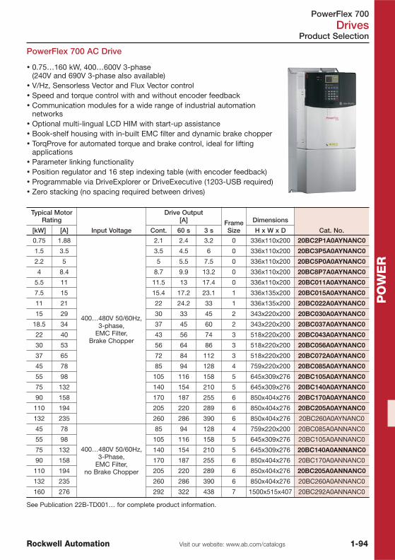
PowerFlex 700 Drives
1-94Visit our website: www.ab.com/catalogsRockwell Automation
PO
WE
R
Product Selection
PowerFlex 700 AC Drive
Typical MotorRating
Input Voltage
Drive Output[A] Frame
Size
Dimensions
Cat. No.[kW] [A] Cont. 60 s 3 s H x W x D
0.75 1.88
400…480V 50/60Hz,3-phase,
EMC Filter,Brake Chopper
2.1 2.4 3.2 0 336x110x200 20BC2P1A0AYNANC0
1.5 3.5 3.5 4.5 6 0 336x110x200 20BC3P5A0AYNANC0
2.2 5 5 5.5 7.5 0 336x110x200 20BC5P0A0AYNANC0
4 8.4 8.7 9.9 13.2 0 336x110x200 20BC8P7A0AYNANC0
5.5 11 11.5 13 17.4 0 336x110x200 20BC011A0AYNANC0
7.5 15 15.4 17.2 23.1 1 336x135x200 20BC015A0AYNANC0
11 21 22 24.2 33 1 336x135x200 20BC022A0AYNANC0
15 29 30 33 45 2 343x220x200 20BC030A0AYNANC0
18.5 34 37 45 60 2 343x220x200 20BC037A0AYNANC0
22 40 43 56 74 3 518x220x200 20BC043A0AYNANC0
30 53 56 64 86 3 518x220x200 20BC056A0AYNANC0
37 65 72 84 112 3 518x220x200 20BC072A0AYNANC0
45 78 85 94 128 4 759x220x200 20BC085A0AYNANC0
55 98 105 116 158 5 645x309x276 20BC105A0AYNANC0
75 132 140 154 210 5 645x309x276 20BC140A0AYNANC0
90 158 170 187 255 6 850x404x276 20BC170A0AYNANC0
110 194 205 220 289 6 850x404x276 20BC205A0AYNANC0
132 235 260 286 390 6 850x404x276 20BC260A0AYNANC0
45 78
400…480V 50/60Hz,3-Phase,
EMC Filter,no Brake Chopper
85 94 128 4 759x220x200 20BC085A0ANNANC0
55 98 105 116 158 5 645x309x276 20BC105A0ANNANC0
75 132 140 154 210 5 645x309x276 20BC140A0ANNANC0
90 158 170 187 255 6 850x404x276 20BC170A0ANNANC0
110 194 205 220 289 6 850x404x276 20BC205A0ANNANC0
132 235 260 286 390 6 850x404x276 20BC260A0ANNANC0
160 276 292 322 438 7 1500x515x407 20BC292A0ANNANC0
See Publication 22B-TD001… for complete product information.
� 0.75…160 kW, 400…600V 3-phase(240V and 690V 3-phase also available)
� V/Hz, Sensorless Vector and Flux Vector control� Speed and torque control with and without encoder feedback� Communication modules for a wide range of industrial automation
networks� Optional multi-lingual LCD HIM with start-up assistance� Book-shelf housing with in-built EMC filter and dynamic brake chopper� TorqProve for automated torque and brake control, ideal for lifting
applications� Parameter linking functionality� Position regulator and 16 step indexing table (with encoder feedback)� Programmable via DriveExplorer or DriveExecutive (1203-USB required)� Zero stacking (no spacing required between drives)
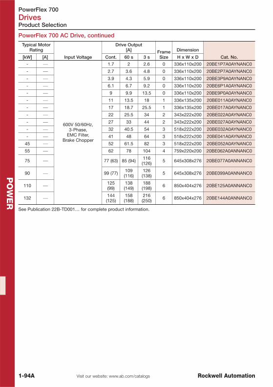
PowerFlex 700Drives
1-94A Visit our website: www.ab.com/catalogs Rockwell Automation
PO
WE
R
Product Selection
PowerFlex 700 AC Drive, continued
Typical MotorRating
Input Voltage
Drive Output[A] Frame
Size
Dimension
Cat. No.[kW] [A] Cont. 60 s 3 s H x W x D
- ⎯
600V 50/60Hz,3-Phase,
EMC Filter,Brake Chopper
1.7 2 2.6 0 336x110x200 20BE1P7A0AYNANC0
- ⎯ 2.7 3.6 4.8 0 336x110x200 20BE2P7A0AYNANC0
- ⎯ 3.9 4.3 5.9 0 336x110x200 20BE3P9A0AYNANC0
- ⎯ 6.1 6.7 9.2 0 336x110x200 20BE6P1A0AYNANC0
- ⎯ 9 9.9 13.5 0 336x110x200 20BE9P0A0AYNANC0
- ⎯ 11 13.5 18 1 336x135x200 20BE011A0AYNANC0
- ⎯ 17 18.7 25.5 1 336x135x200 20BE017A0AYNANC0
- ⎯ 22 25.5 34 2 343x222x200 20BE022A0AYNANC0
- ⎯ 27 33 44 2 343x222x200 20BE027A0AYNANC0
- ⎯ 32 40.5 54 3 518x222x200 20BE032A0AYNANC0
- ⎯ 41 48 64 3 518x222x200 20BE041A0AYNANC0
45 ⎯ 52 61.5 82 3 518x222x200 20BE052A0AYNANC0
55 ⎯ 62 78 104 4 759x220x200 20BE062A0ANNANC0
75 ⎯ 77 (63) 85 (94) 116(126) 5 645x308x276 20BE077A0ANNANC0
90 ⎯ 99 (77) 109(116)
126(138) 5 645x308x276 20BE099A0ANNANC0
110 ⎯ 125(99)
138(149)
188(198) 6 850x404x276 20BE125A0ANNANC0
132 ⎯ 144(125)
158(188)
216(250) 6 850x404x276 20BE144A0ANNANC0
See Publication 22B-TD001… for complete product information.

PowerFlex 700 Drives
1-95Visit our website: www.ab.com/catalogsRockwell Automation
PO
WE
R
Product Selection
Options
Cat. No.
User Interface Modules
Full Numeric LCD 20-HIM-A3
Programming Only LCD 20-HIM-A5
DPI-Port Cable, 1 m 20-HIM-H10
Full Numeric LCD, IP66, includes 3 m cable 20-HIM-C3S
Programming Only LCD, IP66, includes 3 m cable 20-HIM-C5S
Wireless Interface Module Bluetooth DPI, IP20 20-WIM-N1
Wireless Interface Module Bluetooth DPI, IP66 20-WIM-N4S
DPI-Port Cable Extension, 0.30 m 1202-H03
DPI-Port Cable Extension, 1 m 1202-H10
DPI-Port Cable Extension, 3 m 1202-H30
DPI-Port Cable Extension, 9 m 1202-H90
Internal Communication Option
Communication Module, DeviceNet 20-COMM-D
Communication Module, ControlNet 20-COMM-C
Communication Module, ControlNet Fiber 20-COMM-Q
Communication Module, EtherNet/IP 20-COMM-E
Communication Module, RIO 20-COMM-R
Communication Module, RS485 DF1 20-COMM-S
Communication Module, Profibus 20-COMM-P
Communication Module, InterBus 20-COMM-I
Communication Module, CANopen 20-COMM-K
Communication Module, LonWorks 20-COMM-L
Selectable Communication Module, HVAC ModBus RTU, Metasys N2 20-COMM-H
BACnet Communication Module 20-COMM-B
Communication Module, Option Compact I/O to DPI/SCANport module 1769-SM1
Encoder Option
PowerFlex 700 Encoder Feedback, 12/5VDC 20B-ENC-2
PC Programming Tool
USB to DSI/DPI Converter with Software DriveExplorer Light Version 1203-USB
Serial Converter Module with Software DriveExplorer Light Version 1203-SSS
Programming Software
DriveExplorer, Full version 9306-4EXP02ENE
DriveTools SP Suite, DriveExecutive and DriveObserver 9303-4DTS01ENE
Internal Brake Resistors, 5 % Duty Cycle
Brake Resistor Kit, PowerFlex 700 Frame 0, 400…480V, 115 Ohm 20BD-DB1-0
Brake Resistor Kit, PowerFlex 700 Frame 1, 400…480V, 115 Ohm 20BD-DB1-1
Brake Resistor Kit, PowerFlex 700 Frame 2, 400…480V, 68 Ohm 20BD-DB1-2
See Publication 22B-TD001… for complete product information.

PowerFlex 4, 4M, 40, 40P, 400, 70, 700Drives
1-96 Visit our website: www.ab.com/catalogs Rockwell Automation
PO
WE
R
Accessories
External Dynamic Brake Resistors for PowerFlex 4, 4M, 40, 40P, 70 and 700
kWBraking Torque
% of Motor PowerDuty
Cycle % Description Cat. No.
200…240V Drives
0.37 100 % 46 %Dynamic Brake Resistor,
200…480V, 91 Ohm, 86 W
AK-R2-091P500
0.75 100 % 23 % AK-R2-091P500
1.5 100 % 11 % AK-R2-091P500
2.2 100 % 15 % Dynamic Brake Resistor,200…480V, 47 Ohm, 166 W
AK-R2-047P500
4 79 % 11 % AK-R2-047P500
5.5 90 % 10 % Dynamic Brake Resistor,200…480V, 30 Ohm, 260 W
AK-R2-030P1K2
7.5 66 % 10 % AK-R2-030P1K2
11 90 % 10 % �
15 66 % 10 % �
400…480V Drives
0.37 100 % 47 %Dynamic Brake Resistor,
200…480V, 360 Ohm, 86 W
AK-R2-360P500
0.75 100 % 23 % AK-R2-360P500
1.5 100 % 12 % AK-R2-360P500
2.2 100 % 24 %
Dynamic Brake Resistor,200…480V, 120 Ohm, 260 W
AK-R2-120P1K2
4 100 % 13 % AK-R2-120P1K2
5.5 90 % 10 % AK-R2-120P1K2
7.5 66 % 10 % AK-R2-120P1K2
11 90 % 10 % �
15 66 % 10 % �
500…600V Drives �
0.37 100% 46%Dynamic Brake Resistor,
200…480V, 360 Ohm, 86 W
AK-R2-360P500
0.75 100% 23% AK-R2-360P500
1.5 100% 11% AK-R2-360P500
2.2 100% 24%
Dynamic Brake Resistor,200…480V, 120 Ohm, 260 W
AK-R2-120P1K2
4 100% 13% AK-R2-120P1K2
5.5 100% 9% AK-R2-120P1K2
7.5 100% 7% AK-R2-120P1K2
11 100% 9% �
15 100% 7% �
� For 11 and 15 kW applications, use two 7.5 size resistors wired in parallel.� For PowerFlex 40, 40P, 70 and 700For installation instructions refer to publication RA-IN004…For detailed information on dynamic braking refer to publication PFLEX-AT001…

PowerFlex 4, 4M, 40, 40P, 400, 70, 700 Drives
1-97Visit our website: www.ab.com/catalogsRockwell Automation
PO
WE
R
Accessories
Line Reactors, 3 % Input Impedance
Motor terminatorsDescription Cat. No.
Terminator, 380…600V, 0.37…3.7 kW, 6 kHz, IP65 1204-TFA1Terminator, 380…600V, 1.5…600 kW, 2 kHz, IP65 1204-TFB2
kWPowerFlex 4/4M PowerFlex 40/40P PowerFlex 400 PowerFlex 70
Cat. No. Cat. No. Cat. No. Cat. No.
200…240V3-Phase Drives
0.2 1321-3R2-A 1321-3R2-A0.75 1321-3R8-B 1321-3R8-B1.5 1321-3R8-A 1321-3R8-A2.2 1321-3R12-A 1321-3R12-A 1321-3R12-A4 1321-3R18-A 1321-3R18-A 1321-3R18-A
5.5 1321-3R25-A 1321-3R25-A 1321-3R25-A7.5 1321-3R35-A 1321-3R35-A 1321-3R35-A11 1321-3R45-A15 1321-3R55-A
18.5 1321-3R80-A22 1321-3R80-A30 1321-3R100-A37 1321-3R130-A
400…480V3-Phase Drives
0.37 1321-3R2-B 1321-3R2-B0.75 1321-3R2-B 1321-3R2-B1.5 1321-3R4-B 1321-3R4-B2.2 1321-3R4-B 1321-3R4-B 1321-3R8-C4 1321-3R8-B 1321-3R8-B 1321-3R12-B
5.5 1321-3R12-B 1321-3R12-B 1321-3R12-B7.5 1321-3R18-B 1321-3R18-B 1321-3R18-B11 1321-3R25-B 1321-3R25-B 1321-3R25-B15 1321-3R35-B
18.5 1321-3R35-B22 1321-3R45-B30 1321-3R55-B37 1321-3R80-B45 1321-3R80-B55 1321-3R100-B75 1321-3R130-B90 1321-3R160-B110 1321-3R200-B132 1321-3RB250-B160 1321-3RB320-B200 1321-3RB400-B250 1321-3R500-B
500…600V3-Phase Drives
0.37 1321-3R1-B0.75 1321-3R2-B 1321-3R2-B1.5 1321-3R4-B 1321-3R4-B2.2 1321-3R4-B 1321-3R4-B4 1321-3R8-C 1321-3R8-C
5.5 1321-3R12-B 1321-3R12-B7.5 1321-3R12-B 1321-3R12-B11 1321-3R18-B 1321-3R18-B15 1321-3R25-B
18.5 DC reactorBulit in22
30…110
For technical details refer to publication 1321-TD001…

Bulletin 194C, 194L, 194EControl and Load Switches
1-98 Visit our website: www.ab.com/catalogs Rockwell Automation
PO
WE
R
Switch Selection
Product Line Overview
Bulletin 194L 194E 194E
TypeControl and Load
Switches12…40 A
Load Switches16…100 A
Load Switches125…315 A
Features
� 12, 16, 20, 25, 40 A� Inductive Load-Rated
control and load switch� 1 to 6 pole switch control
configurations for OFF-ON, Change-over, Star-Delta (Wye- Delta),Reversing, Ammeter,Voltmeter, and StepSwitch applications
� 16, 25, 32, 40, 63, 80,100 A
� Inductive Load-Ratedload switch
� 3 or 6 pole switchconfigurations for OFF-ON or Change-overapplications
� 125, 160, 250, 315 A� Inductive Load-Rated
load switch� 3 or 4 pole switch
configurations for OFF-ON applications
� UL, CSA ratings “Suitable as At-Motor Disconnect”� Front/Door or Base/DIN rail mounting� Made of environmentally friendly materials
Actuators
� Uniformly styledactuators available inselector knob, disk-style,rectangular-style andkey-operated versions(Type 1/12/3R, IP66)
� Actuator colours ingrey/black or red/yellowand padlockable versions
� Legend plates availablein O-I internationalmarkings and text styles
� Uses 194L actuators forstandardization amongline, available in selector-knob, disk-style,rectangular-style andkey-operated versions(Type 1/12/3R, IP66)
� Actuator colours ingrey/black or red/yellowand padlockable versions
� Legend plates availablein O-I internationalmarkings and text styles
� Uses larger 194Eactuators available inselector knob, disk-style,(Type 1/12/3R, IP66)
� Actuator colours ingrey/black or red/yellowand padlockable versions
� Legend plates availablein O-I internationalmarkings and text styles
Open Switch orEnclosed
Available as open switch or in IP66 thermoplasticenclosure Available as open switch
UL/CSA El. Ratings
Rated Voltage Ue [V AC] 600V
Rated Current Ie [A] 12…40 A @ 600V 16…100 A @ 600V 125…315 A @ 600V
Short Circuit Ratings [A] 5 kA
Switching Rate [ops/h] 120
Mechanical Life [ops] 1 million 0.2 million 0.1 million (125…160 A)0.075 million (250…315 A)
Protection Class Acc. to IEC 529 Switch bodies IP20 actuators IP66
Protection Class Acc. to UL CSA Actuators UL Type 1/12 (selector style) and UL 1/3/3R/12 (disc style)
Optional AccessoriesMulti-length shafts and
shaft extension kits,terminal covers
Multi-length shafts and shaft extension kits, auxiliarycontacts, power poles, grounding poles, terminal covers
Standards/Approvals UL 508, CSA C22.2 No. 14, IEC 947-3Low voltage switch gear and control gear part 3, CE
Product Selection See page 1-99 See page 1-105 See page 1-105

Bulletin 194LControl and Load Switches
1-99Visit our website: www.ab.com/catalogsRockwell Automation
PO
WE
R
+
Switch Body Actuator
Product Selection
� Rated current up to 40 A� Large selection of functions and
switching positions� Screws and central fixture ø 22.5 mm� Front- or base mounting� Finger-proof switch bodies per IP20� Water spray and dust-proof actuator
per IP66� Easily accessible terminals� Clearly marked terminals
Control and Load Switches 194L
Switch Bodies for Bulletin 194L, Front/Base Mounting
Function
IAC-21A
[A] Poles
Front/DoorMounting
Base/DIN RailMounting
Combinations
Actuator / Legend Plate
Cat. No. Cat. No. Size Type No.
ON-OFF Switches
1
0
12
1 194L-E12-1751 194L-A12-1751
4, 646
46
194L-HE…A, E
A, E, I, P, SA, E, G�, I, L, N�, S
194L-HC…B, D�
A, C�, E, I, LG�, N�
001175175
001175175
2 194L-E12-1752 194L-A12-1752
3 194L-E12-1753 194L-A12-1753
4 194L-E12-1754 194L-A12-1754
6 194L-E12-1756 194L-A12-1756
16
1 194L-E16-1751 194L-A16-1751
2 194L-E16-1752 194L-A16-1752
3 194L-E16-1753 194L-A16-1753
4 194L-E16-1754 194L-A16-1754
6 194L-E16-1756 194L-A16-1756
20
1 194L-E20-1751 194L-A20-1751
2 194L-E20-1752 194L-A20-1752
3 194L-E20-1753 194L-A20-1753
4 194L-E20-1754 194L-A20-1754
6 194L-E20-1756 194L-A20-1756
25
1 194L-E25-1751 194L-A25-1751
2 194L-E25-1752 194L-A25-1752
3 194L-E25-1753 194L-A25-1753
4 194L-E25-1754 194L-A25-1754
6 194L-E25-1756 194L-A25-1756
32
3 194L-E32-1753 194L-A32-1753
4 194L-E32-1754 194L-A32-1754
6 194L-E32-1756 194L-A32-1756
40
3 194L-E40-1753 194L-A40-1753
4 194L-E40-1754 194L-A40-1754
6 194L-E40-1756 194L-A40-1756
Ordering Example: Switch Body: 194L-E12-1751; Actuator for Screw Fixture Type A: 194L-HE4A-175� Key out position see page 1-104.�With both 0-1 and OFF/ON inscriptions.
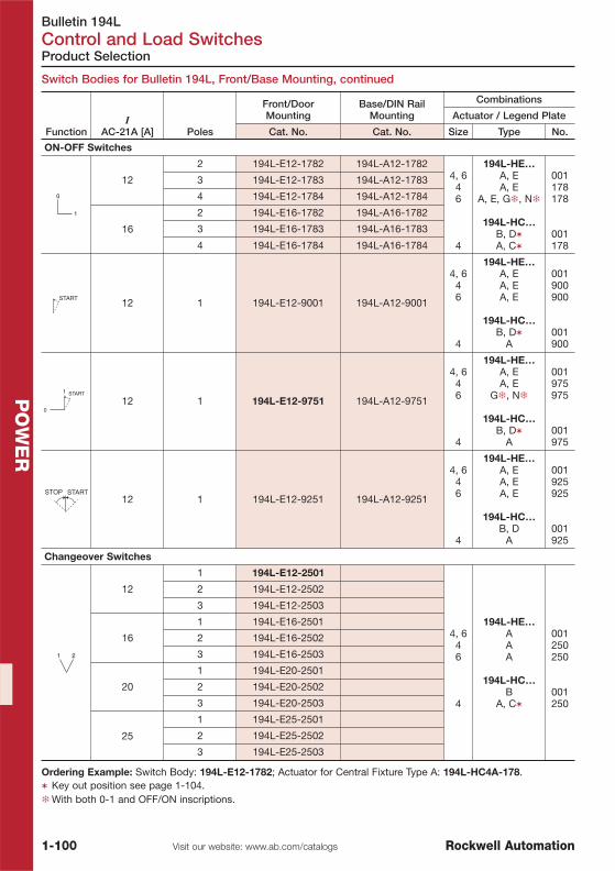
Bulletin 194LControl and Load Switches
1-100 Visit our website: www.ab.com/catalogs Rockwell Automation
PO
WE
R
Switch Bodies for Bulletin 194L, Front/Base Mounting, continued
Product Selection
FunctionI
AC-21A [A] Poles
Front/DoorMounting
Base/DIN RailMounting
Combinations
Actuator / Legend Plate
Cat. No. Cat. No. Size Type No.
ON-OFF Switches
12
2 194L-E12-1782 194L-A12-17824, 6
46
4
194L-HE…A, EA, E
A, E, G�, N�
194L-HC…B, D�A, C�
001178178
001178
3 194L-E12-1783 194L-A12-1783
4 194L-E12-1784 194L-A12-1784
16
2 194L-E16-1782 194L-A16-1782
3 194L-E16-1783 194L-A16-1783
4 194L-E16-1784 194L-A16-1784
START12 1 194L-E12-9001 194L-A12-9001
4, 646
4
194L-HE…A, EA, EA, E
194L-HC…B, D�
A
001900900
001900
START1
012 1 194L-E12-9751 194L-A12-9751
4, 646
4
194L-HE…A, EA, E
G�, N�
194L-HC…B, D�
A
001975975
001975
STOP START12 1 194L-E12-9251 194L-A12-9251
4, 646
4
194L-HE…A, EA, EA, E
194L-HC…B, D
A
001925925
001925
Changeover Switches
12
1 194L-E12-2501
4, 646
4
194L-HE…AAA
194L-HC…B
A, C�
001250250
001250
2 194L-E12-2502
3 194L-E12-2503
16
1 194L-E16-2501
2 194L-E16-2502
3 194L-E16-2503
20
1 194L-E20-2501
2 194L-E20-2502
3 194L-E20-2503
25
1 194L-E25-2501
2 194L-E25-2502
3 194L-E25-2503
Ordering Example: Switch Body: 194L-E12-1782; Actuator for Central Fixture Type A: 194L-HC4A-178.� Key out position see page 1-104.�With both 0-1 and OFF/ON inscriptions.

Bulletin 194LControl and Load Switches
1-101Visit our website: www.ab.com/catalogsRockwell Automation
PO
WE
R
Switch Bodies for Bulletin 194L, Front/Base Mounting, continued
Product Selection
FunctionI
AC-21A [A] Poles
Front/DoorMounting
Base/DIN RailMounting
Combinations
Actuator / Legend Plate
Cat. No. Cat. No. Size Type No.
Changeover Switches
12
1 194L-E12-3251 194L-A12-3251
4, 646
4
194L-HE…A
A, P, SA, S
194L-HC…B, D�A, C�
001325325
001325
2 194L-E12-3252 194L-A12-3252
3 194L-E12-3253 194L-A12-3253
4 194L-E12-3254 194L-A12-3254
16
1 194L-E16-3251 194L-A16-3251
2 194L-E16-3252 194L-A16-3252
3 194L-E16-3253 194L-A16-3253
4 194L-E16-3254 194L-A16-3254
20
1 194L-E20-3251 194L-A20-3251
2 194L-E20-3252 194L-A20-3252
3 194L-E20-3253 194L-A20-3253
4 194L-E20-3254 194L-A20-3254
25
1 194L-E25-3251 194L-A25-3251
2 194L-E25-3252 194L-A25-3252
3 194L-E25-3253 194L-A25-3253
4 194L-E25-3254 194L-A25-3254
323 194L-E32-3253 194L-A32-3253
4 194L-E32-3254 194L-A32-3254
403 194L-E40-3253 194L-A40-3253
4 194L-E40-3254 194L-A40-3254
0
2112 1 194L-E12-3751
4, 646
4
194L-HE…AAA
194L-HC…B, D�A, C�
001375375
001375
Reversing Switches
12 3 194L-E12-7303 194L-A12-73034, 6
46
4
194L-HE…A
A, SA, S
194L-HC…B, D�A, C�
001325325
001325
16 3 194L-E16-7303 194L-A16-7303
20 3 194L-E20-7303 194L-A20-7303
25 3 194L-E25-7303 194L-A25-7303
40 3 194L-E40-7303 194L-A40-7303
Star-Delta Switches
16 3 194L-E16-7323 194L-A16-7323 4, 646
4
194L-HE…AAA
194L-HC…B, D�A, C�
001725725
001725
25 3 194L-E25-7323 194L-A25-7323
40 3 194L-E40-7323
Ordering Example: Switch Body: 194L-E12-3251; Actuator for Central Fixture Type A: 194L-HC4A-325.� Key out position see page 1-104.

Bulletin 194LControl and Load Switches
1-102 Visit our website: www.ab.com/catalogs Rockwell Automation
PO
WE
R
Product Selection
Switch Bodies for Bulletin 194L, Front/Base Mounting, continued
FunctionI
AC-21A [A] Poles
Front/DoorMounting
Base/DIN RailMounting
Combinations
Actuator / Legend Plate
Cat. No. Cat. No. Size Type No.
Step Switches
12
1 194L-E12-4251 194L-A12-4251
4, 646
4
194L-HE…AAA
194L-HC…B, D�A, C�
001425425
001425
2 194L-E12-4252
3 194L-E12-4253
16
1 194L-E16-4251 194L-A16-4251
2 194L-E16-4252
3 194L-E16-4253
25
1 194L-E25-4251 194L-A25-4251
2 194L-E25-4252
3 194L-E25-4253
12
1 194L-E12-4511
4, 646
4
194L-HE…AAA
194L-HC…B, D�
A
001451451
001451
2 194L-E12-4512
3 194L-E12-4513
16
1 194L-E16-4511
2 194L-E16-4512
3 194L-E16-4513
25
1 194L-E25-4511
2 194L-E25-4512
3 194L-E25-4513
12 1 194L-E12-4271
4, 646
4
194L-HE…AAA
194L-HC…B, D�A, C�
001427427
001427
12
1 194L-E12-5251 4, 646
4
194L-HE…AAA
194L-HC…B, D�A, C�
001525525
001525
2 194L-E12-5252
3 194L-E12-5253
12 1 194L-E12-5261
4, 646
4
194L-HE…AAA
194L-HC…B, D�A, C�
001526526
001526
Ordering Example: Switch Body: 194L-E12-4251; Actuator for Central Fixture Type B: 194L-HCB-001.� Key out position see page 1-104.

Bulletin 194LControl and Load Switches
1-103Visit our website: www.ab.com/catalogsRockwell Automation
PO
WE
R
Product Selection
Switch Bodies for Bulletin 194L, Front/Base Mounting, continued
FunctionI
AC-21A [A] Poles
Front/DoorMounting
Base/DIN RailMounting
Combinations
Actuator / Legend Plate
Cat. No. Cat. No. Size Type No.
Voltmeter Selector Switches
12 1 194L-E12-8251 194L-A12-8251
4, 646
4
194L-HE…A
A, PA
194L-HC…B, D�
A
001825825
001825
12 1 194L-E12-8271 194L-A12-8271
4, 646
4
194L-HE…AAA
194L-HC…B, D�
A
001827827
001827
SN TN
0
RN12 1 194L-E12-8291 194L-A12-8291
4, 646
4
194L-HE…AAA
194L-HC…B, D�
A
001829829
001829
Ammeter Selector Switches
12 1 194L-E12-8751 194L-A12-8751
4, 646
4
194L-HE…A
A, PA
194L-HC…B, D�
A
001875875
001875
12 1 194L-E12-8761 194L-A12-8761
4, 646
4
194L-HE…AAA
194L-HC…B, D�
A
001876876
001876
Ordering Example: Switch Body: 194L-E12-8751; Actuator for Central Fixture Type A: 194L-HC4A-875.� Key out position see page 1-104.

Bulletin 194LControl and Load Switches
1-104 Visit our website: www.ab.com/catalogs Rockwell Automation
PO
WE
R
Type Key Out Position
With Legend Plate48 x 48 mm
Without LegendPlate
Cat. No. Cat. No.
A Standard Switch 194L-HC4A-xxx
B without Legend Plate 194L-HCB-001
C or D with Key Operator 194L-HC4CC-xxx 194L-HCDC-001
194L-HC4CD-xxx 194L-HCDD-001
194L-HC4CG-xxx 194L-HCDG-001
194L-HC4CH-xxx 194L-HCDH-001
194L-HC4CK-xxx 194L-HCDK-001
E Disconnect Switch 194L-HC4E-xxx
I Emergency Stop 194L-HC4I-xxx
L Main Switch/Emergency 194L-HC4L-xxx
xxx Legend plates and actuator combinations see page 1-99.
A B C D E G
I N L P, Q S
Product Selection
Type
With Legend Plate48 x 48 mm
With Legend Plate67 x 67 mm
Cat. No. Cat. No.
A Standard Switch 194L-HE4A-xxx 194L-HE6A-xxx
E Disconnect Switch (1 padlock) 194L-HE4E-xxx 194L-HE6E-xxx
I Emergency Stop 194L-HE4I-xxx 194L-HE6I-xxx
L Main Switch/Emergency (1 padlock) 194L-HE4L-xxx 194L-HE6L-xxx
S With legend plate 194L-HE4S-xxx 194L-HE6S-xxx
G Disconnect Switch (3 padlocks) 194E-HE4G-xxx 194L-HE6G-xxx
N Main Switch/Emergency (3 padlocks) 194E-HE4N-xxx 194L-HE6N-xxx
P With DIN 45 mm Panel Cut-out 194L-HE4P-xxx
xxx Legend plates and actuator combinations see page 1-99.
Actuators for 194L
Actuators with Central Fixture ø 22,5 mm
Actuators for Front or Base Mounting

Bulletin 194EControl and Load Switches
1-105Visit our website: www.ab.com/catalogsRockwell Automation
PO
WE
R
� Front- and base mounting� Finger-proof switch body per IP20� Water spray and dust-proof per IP66� Easily accessible terminals� Clearly marked terminals� Wide range of accessories
Switch Bodies for 194E (125…315 A), Front/Base Mounting
194E (125 A …315 A)
Control and Load Switches 194E
Switch Bodies for 194E (16…100 A), Front/Base Mounting
Product Selection
194E (16 A…100 A)
FunctionI
AC-21A [A] Poles
Front/DoorMounting
Base/DIN RailMounting
Combinations
Actuator / Legend Plate
Cat. No. Cat. No. Size Type No.
ON-OFF Switches
1
0
16
3
194E-E16-1753 194E-A16-1753
468
46
194L-HE…A, E, I, L
A, E, G�, I, L, N�A, G�, I, N�
194L-HC…A, E, G�, I, L, N�A, E, G�, I, L, N�
175175175
175175
25 194E-E25-1753 194E-A25-1753
32 194E-E32-1753 194E-A32-1753
40 194E-E40-1753 194E-A40-1753
63 194E-E63-1753 194E-A63-1753
80 194E-E80-1753 194E-A80-1753
100 194E-E100-1753 194E-A100-1753
Changeover Switches
0
21
16 3 194E-E16-3753 194E-A16-3753
468
46
194L-HE…A, EA, E
A
194L-HC… �A, E, I, LA, E, I, L
375375375
375375
25 3 194E-E25-3753 194E-A25-3753
32 3 194E-E32-3753 194E-A32-3753
40 3 194E-E40-3753 194E-A40-3753
63 3 194E-E63-3753 194E-A63-3753
80 3 194E-E80-3753 194E-A80-3753
100 3 194E-E100-3753 194E-A100-3753
Ordering Example: Switch Body: 194E-E25-1753; Actuator for Screw Fixture Type A: 194L-HE4A-175.�Not available for 80/100 A switches
Function
IAC-21A
[A]
IAC-23A
[kW] Poles
Front/DoorMounting
Base/DIN RailMounting
Combinations
Actuator / Legend Plate
Cat. No. Cat. No. Size Type No.
ON-OFF Switches
1
0
125 45
3
194E-E125-1753 194E-A125-1753
813
194E-HE…A, G�, I�, N�A, G�, I�, N�
175175
160 55 194E-E160-1753 194E-A160-1753
250 90 194E-E250-1753 194E-A250-1753
315 110 194E-E315-1753 194E-A315-1753
125 45
4
194E-E125-1754 194E-A125-1754
160 55 194E-E160-1754 194E-A160-1754
250 90 194E-E250-1754 194E-A250-1754
315 110 194E-E315-1754 194E-A315-1754
Ordering Example: Switch Body: 194E-A125-1753; Actuator for Screw Fixture Type A: 194E-HE8A-175.� With both 0-1 and OFF/ON inscriptions.

Bulletin 194EControl and Load Switches
1-106 Visit our website: www.ab.com/catalogs Rockwell Automation
PO
WE
R Type
With Legend Plate0-I, 48 x 48 mm
With Legend Plate0-I, 67 x 67 mm
With Legend Plate0-I, 88 x 88 mm
Cat. No. Cat. No. Cat. No.
A Standard Switch 194L-HE4A-175 194L-HE6A-175 194L-HE8A-175
E Disconnect Switch 194L-HE4E-175 194L-HE6E-175
G Disconnect Switch 194E-HE4G-175 194L-HE6G-175 194L-HE8G-175
I Emergency Stop 194L-HE4I-175 194L-HE6I-175
L Disconnect Switch/Emergency Stop 194L-HE4L-175 194L-HE6L-175
N Disconnect Switch/Emergency Stop 194E-HE4N-175 194L-HE6N-175 194L-HE8N-175
S Standard Switch with Label S 194L-HE4S-175 194L-HE6S-175
Type
With Legend Plate48 x 48 mm
With Legend Plate67 x 67 mm
Without LegendPlate
Cat. No. Cat. No. Cat. No.
A Standard Switch 194L-HC4A-175 194L-HC4A-001
E Disconnect Switch 194L-HC4E-175 194L-HC4E-001
G Disconnect Switch 194L-HC6G-175
I Emergency Stop 194L-HC4I-175
L Disconnect Switch/Emergency Stop 194L-HC4L-175
N Disconnect Switch/Emergency Stop 194L-HC6N-175
A E G I L N S
Actuators with Central Fixture ø 22,5 mm
Actuators for Front or Base Mounting (16…100 A)
Actuators for Front or Base Mounting (125…315 A)
Product Selection: 194E
Type
With Legend Plate0-I, 88 x 88 mm
With Legend Plate0-I, 130 x 130 mm
Cat. No. Cat. No.
A Standard Switch 194E-HE8A-175 194E-HE13A-175
G Disconnect Switch 194E-HE8G-175 194E-HE13G-175
I Emergency Stop 194E-HE8I-175 194E-HE13I-175
N Disconnect Switch/Emergency Stop 194E-HE8N-175 194E-HE13N-175
For other Legend Plates and Actuator Combinations see Page 1-105.
Actuators for Bulletin 194E

Bulletin 194EControl and Load Switches
1-107Visit our website: www.ab.com/catalogsRockwell Automation
PO
WE
R
Product Selection
194E Load Switches in Enclosure, Complete Switches
Metric Conduit Openings
Poles
AC-21A/500V
AC-23A/400V
Main Switches/EmergencyRed/Yellow
Disconnect SwitchBlack/Grey
[A] [kW] Cat. No. Cat. No.
3
16 7.5 194E-Y16M-1753-4N 194E-Y16M-1753-4G
25 11 194E-Y25M-1753-6N 194E-Y25M-1753-6G
32 15 194E-Y32M-1753-6N 194E-Y32M-1753-6G
40 18.5 194E-Y40M-1753-6N 194E-Y40M-1753-6G
63 22 194E-Y63M-1753-6N 194E-Y63M-1753-6G
80 37 194E-Y80M-1753-6N 194E-Y80M-1753-6G
100 45 194E-Y100M-1753-6N 194E-Y100M-1753-6G
6
16 7.5 194E-Y16M-1756-6N 194E-Y16M-1756-6G
25 11 194E-Y25M-1756-6N 194E-Y25M-1756-6G
32 15 194E-Y32M-1756-6N 194E-Y32M-1756-6G
40 18.5 194E-Y40M-1756-6N 194E-Y40M-1756-6G
63 22 194E-Y63M-1756-6N 194E-Y63M-1756-6G
Poles
AC-21A/500V
AC-23A/400V
Standard Switch O-I
[A] [kW] Cat. No.
3
16 7.5 194E-Y16M-1753-4A
25 11 194E-Y25M-1753-6A
32 15 194E-Y32M-1753-6A
40 18.5 194E-Y40M-1753-6A
63 22 194E-Y63M-1753-6A
80 37 194E-Y80M-1753-6A
100 45 194E-Y100M-1753-6A
6
16 7.5 194E-Y16M-1756-6A
25 11 194E-Y25M-1756-6A
32 15 194E-Y32M-1756-6A
40 18.5 194E-Y40M-1756-6A
63 22 194E-Y63M-1756-6A
- IP66

Bulletin 194L, 194EControl and Load Switches
1-108 Visit our website: www.ab.com/catalogs Rockwell Automation
PO
WE
R
Accessories
Accessories for Bulletin 194L and 194E
Description For Use With PQ Cat. No.
Plastic Shafts:
Length 44 mm194L-A,194E-A 5
194L-G2830
Length 52 mm 194L-G3194
Length 57 mm 194L-G3195
Shaft ExtensionsLength 24 mm. Max. nos. of pieces per device is 4.2 pieces per set.
194L-A,194E-A 10 194L-G2853
Metal Shaft ExtensionsLocking possibility with provision for locking inposition «0» 194L-A,
194E-ALength 110...235 mm1
194L-G3393
Length 230...350 mm 194L-G3394
InsertsFor modifying Bulletin 194L-G3393 and 194L-G3394 metalshaftextensions with switch position: I-0 90°.Provision for padlock in position «0».
194L-A 10 194L-G3398
Additional NameplatesFor actuators:
194L-H...48 x 48, 64 x 64 and 67 x 67 mm
5
194L-G3667
88 x 88, 90 x 90, 130 x 130 and 135 x 135 mm 194L-G3515
Terminal Covers 3/4 poles
194L-E12/16
10
194L-E12-C34
194L-E20/25 194L-E20-C34
194L-A12/16 194L-A12-C34
194L-A20/25 194L-A20-C34
Terminal Covers 3 poles
194E-16
2
194E-16-C3
194E-25/32 194E-25-C3
194E-40/63 194E-40-C3
194E-80/100 194E-80-C3
Terminal Covers 4 poles
194E-16�
2
194E-16-C1
194E-25/32 194E-25-C4
194E-40/63 194E-40-C4
194E-80/100 194E-80-C4
� 1-pole cover to add to 194E-16-C3PQ = Package Quantity

Bulletin 194EControl and Load Switches
1-109Visit our website: www.ab.com/catalogsRockwell Automation
PO
WE
R
Accessories
Accessories for Bulletin 194E (up to 100 A)
Description For Use With Cat. No.
Auxiliary Contact Blocks1 N.O.+ 1 N.C. for left- or right-side mounting
194E-E25...100 194E-E-P11
194E-A25...100 194E-A-P11
Auxiliary Contact Blocks1 early-make and 1 late-break contact for left- or right-side mounting
194E-E25...100 194E-E-PL11
194E-A25...100 194E-A-PL11
18
1738
37
Auxiliary Contact Blocks1 early-break contact for left- or right-side mounting.
194E-E16 194E-E16-PD10
194E-E25...100 194E-E-PD10
194E-A16 194E-A16-PD10
194E-A25...100 194E-A-PD10
Auxiliary Contact Blocks2 N.O.+ 2 N.C. for left- or right-side mounting
194E-E25…100 194E-E-P22
194E-A25…100 194E-A-P22
N
N
Neutral Terminal
194E-E16 194E-E16-TN194E-E25/32 194E-E32-TN194E-E40/63 194E-E63-TN194E-E80/100 194E-E100-TN
194E-A16 194E-A16-TN194E-A25/32 194E-A32-TN194E-A40/63 194E-A63-TN194E-A80/100 194E-A100-TN
PE
PE
Earth Terminal
194E-E16 194E-E16-PE194E-E25/32 194E-E32-PE194E-E40/63 194E-E63-PE194E-E80/100 194E-E100-PE
194E-A16 194E-A16-PE194E-A25/32 194E-A32-PE194E-A40/63 194E-A63-PE194E-A80/100 194E-A100-PE
N
N
Fourth Polesearly-make contact
194E-E16 194E-E16-NP194E-E25 194E-E25-NP194E-E32 194E-E32-NP194E-E40 194E-E40-NP194E-E63 194E-E63-NP194E-E80 194E-E80-NP194E-E100 194E-E100-NP194E-A16 194E-A16-NP194E-A25 194E-A25-NP194E-A32 194E-A32-NP194E-A40 194E-A40-NP194E-A63 194E-A63-NP194E-A80 194E-A80-NP194E-A100 194E-A100-NP
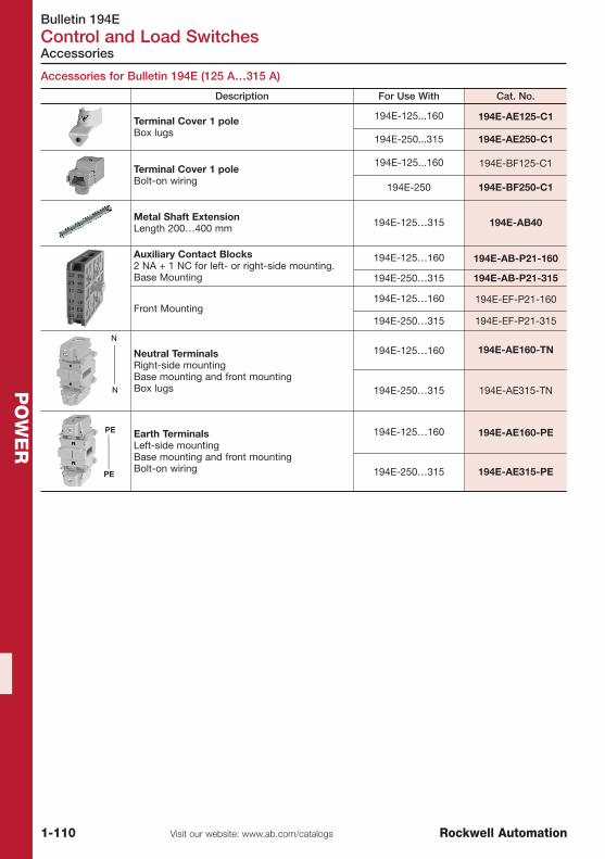
Bulletin 194EControl and Load Switches
1-110 Visit our website: www.ab.com/catalogs Rockwell Automation
PO
WE
R
Accessories
Accessories for Bulletin 194E (125 A…315 A)
Description For Use With Cat. No.
Terminal Cover 1 poleBox lugs
194E-125...160 194E-AE125-C1
194E-250...315 194E-AE250-C1
Terminal Cover 1 poleBolt-on wiring
194E-125...160 194E-BF125-C1
194E-250 194E-BF250-C1
Metal Shaft ExtensionLength 200…400 mm 194E-125…315 194E-AB40
Auxiliary Contact Blocks2 NA + 1 NC for left- or right-side mounting.Base Mounting
194E-125…160 194E-AB-P21-160
194E-250…315 194E-AB-P21-315
Front Mounting194E-125…160 194E-EF-P21-160
194E-250…315 194E-EF-P21-315
Neutral TerminalsRight-side mountingBase mounting and front mountingBox lugs
194E-125…160 194E-AE160-TN
194E-250…315 194E-AE315-TN
Earth TerminalsLeft-side mountingBase mounting and front mountingBolt-on wiring
194E-125…160 194E-AE160-PE
194E-250…315 194E-AE315-PE
EC2010_Chap_1_RSA:1a_Circuit Breakers.qxd 08.06.2010 10:47 Seite 1-110

Visit our website: www.ab.com/catalogsRockwell Automation
TABLE OF CONTENTS
2-1
Logic
Relays and Timers 2-2
Solid State Devices 2-20
Temperature Controllers 2-22
Programmable Controllers 2-23
Circuit Protection 2-38
Surge and Filter Protection 2-53
Power Supplies 2-57

Bulletin 700Relays and Timers
2-2 Visit our website: www.ab.com/catalogs Rockwell Automation
LO
GIC
Relays 700-HA, HC, HK
Bulletin 700-HA 700-HC 700-HK
Type General-Purpose Relay Interposing/Isolation Relay Interposing/Isolation Relay
Features
� Pin-style terminalsStandard ON/OFF flag
indicatorElectrical schematic on face
Clear cover for visualinspection
Optional Ppsh-to-test andmanual override
Optional LED
� Blade-style terminals� Standard ON/OFF flag
indicator� Electrical schematic on
face� Clear cover for visual
inspection� Optional push-to-test and
manual override� Optional LED
� Optional pilot light � Retainer clip (comes with
socket)� Low switching capacity� Push-to-test & manual
override
Contact Ratings
Contact Form DPDT, 3PDT DPDT, 4PDT SPDT, DPDT
Contact Type Single, Bifurcated Single Single
Contact Material AgNi, AgNi + Gold AgNi, AgNi + Gold AgNi, AgNi + Gold
Max. operatingcurrent underresistive load
10 A 10 A (DPDT)7 A (4PDT) 8 A (DPDT), 16 A (SPDT)
Coil Ratings
Coil Voltage
AC: 6, 12, 24, 48, 110, 120,208, 230, 240, 277V
DC: 6, 12, 24, 36, 48, 60, 80,110, 125, 140, 220V
AC: 6, 12, 24, 120, 240VDC: 6, 12, 24, 48, 110V
AC: 6, 12, 24, 120, 240VDC: 6, 12, 24, 48, 110V
Electrical Ratings
DielectricWithstand Voltage
Pole-to-pole: 2000VContact-to-coil: 2000V
Contact-to-frame: 2000V
Pole-to-pole: 1000VContact-to-coil: 2000V
Contact-to-frame: 2000V
Pole-to-pole: 1500V ACContact-to-coil: 1500V AC
Contact-to-frame: 1500V AC
Electric ServiceLife (cycles) 100 000 minimum 100 000 minimum 100 000 minimum
Reference
Certifications CE, cULus, cURus, CSA,Lloyds
CE, cULus, cURus, CSA,Lloyds CE, UL, UR, CSA
Socket Cat. No(s).
700-HN100, 700-HN101,700-HN125, 700-HN126,700-HN204, 700-HN205,700-HN204, 700-HN205
700-HN103, 700-HN128,700-HN104
700-HN121, -HN221700-HN122, -HN222700-HN223, -HN224
Product Selection See page 2-6 See page 2-8 See page 2-9
Product Line Overview
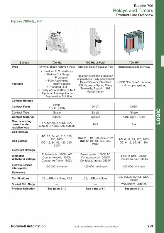
Bulletin 700Relays and Timers
2-3Visit our website: www.ab.com/catalogsRockwell Automation
LO
GIC
Product Line Overview
Relays 700-HL, HP
Bulletin 700-HL 700-HL (2-Pole) 700-HP
Type Terminal Block Relays 1-Pole Terminal Block Relays 2-Pole Interposing/Isolation Relay
Features
� Ideal for PLC Interfaces� Built-in Coil Surge
Protection� Fully Assembled
Relay/Sockets� Standard LED
� Relay or Solid-state Output� Optional: Leakage Current
Suppression Solution
Ideal for interposing isolationapplications, Fully Assembled
Relay/Sockets, StandardLED, Screw or Spring Clamp
Terminals, Snap-in 1492Marker Option
� PCB “Pin Style” mounting� 5 mm pin spacing
Contact Ratings
Contact Form SPDT1 N.O. (SSR) DPDT DPDT
Contact Type Single Single Single
Contact Material AgSnO AgSnO AgNi, AgNi + Gold
Max. operatingcurrent underresistive load
6 A (SPDT), 2 A (SSR DCoutput), 1 A (SSR AC output) 10 A 8 A
Coil Ratings
Coil Voltage
AC: 12, 24, 48, 110, 120,230, 240V
DC: 12, 24, 48, 125, 230,240V
AC: 24, 110, 120, 230, 240VDC: 12, 24, 48, 125, 230,
240V
AC: 6, 12, 24, 120, 240VDC: 6, 12, 24, 48, 110V
Electrical Ratings
DielectricWithstand Voltage
Pole-to-pole: 1000V ACContact-to-coil: 4000V
Contact-to-frame: 1500V
Pole-to-pole: 1000V ACContact-to-coil: 5000V
Contact-to-frame: 2500V
Pole-to-pole: 2000VContact-to-coil: 5000V
Electric ServiceLife (cycles) 100 000 minimum 100 000 minimum 100 000 minimum
Reference
Certifications CE, cURus, cULus, ABS CE, cURus, cULus CE, cULus, cURus, CSA,Lloyds
Socket Cat. No(s). — — 700-HN123, -HN130
Product Selection See page 2-10 See page 2-11 See page 2-12

Bulletin 700Relays and Timers
2-4 Visit our website: www.ab.com/catalogs Rockwell Automation
LO
GIC
Product Line Overview
Timing Relays 700-FE, FS
Bulletin 700-FE 700-FS
Type DIN Rail Timer DIN Rail Timer
Features
� Only 17.5 mm wide� 5 A contact rating
� Multifunction or single function� No additional socket required
� Only 22.5 mm wide� 8 A contact rating
� Multifunction or single function� No additional socket required
� Optional: � Star-delta timing function
� True off-delay timing function� Hazardous location certification
Control Outputs:Time LimitInstantaneous
1 N.O. or SPDT timed SPDT or DPDT or 2 N.O. + 1 common
Operation Modes:
On-delayOff-delayOne shot
Repeat cycle-pulseFleeting off-delayPulse converter
11 Different timing modes
Time Range 0.05 s…10 hr 0.05 s…60 hr
Supply Voltage
24V AC/DC110…240V AC
24…48V AC/DC24…240V AC
12V DC24V…48V DC24V…240V AC
Contact Rating at120V AC 5 A 8 A
Certifications CE, cULus CE, cULus
Product Selection See page 2-13 See page 2-14

Bulletin 700Relays and Timers
2-5Visit our website: www.ab.com/catalogsRockwell Automation
LO
GIC
Product Line Overview
Control Relays 700-M, 700-CF
Bulletin 700-K 700-CF 700-CRF
Type Miniature Control Relay Control Relay
Spring ClampTerminals � — �
Screw Terminals � � —
Features
� Smallest size� Long life
� Low power consumption� Switch up to 690V AC and
DC
� Mechanically linked contacts� Timer and latch operations
� Switch up to 690V AC and DC� Bulletin 700S-CF for safety circuits
Contact Form 4-8 Poles Double Break 4…12 Poles double break
Contact Type Bifurcated Cross stamp or bifurcated
Contact Material Silver Silver, gold
Electrical
Max. Current ACResistive 10 A 20 A (relay)
10 A (adder deck)
Min. load 15V, 2 mA (700-K) 17V, 10 mA (Silver)5V, 3 mA (Gold)
Coil Voltage 12…600V AC9…250V DC
12…600V AC9…250V DC
Coil VoltagePickup
85…110% AC Coils,80…110% DC Coils
85…110% AC coils,80…110% DC coils
DielectricWithstand 2640V 2640V
Reference
Electric ServiceLife (cycles) 800'000 at 10 A 1'200'000 at 10 A
Certifications CE, cULus, CCC CE, cULus, CSA, CCC
Sockets DIN Rail or panel mount DIN Rail or panel mount
Product Selection See page 2-17 See page 2-18

Bulletin 700-HARelays and Timers
2-6 Visit our website: www.ab.com/catalogs Rockwell Automation
LO
GIC
Product Selection
Description Wiring Diagrams Contact Rating Coil Voltage Cat. No. �‡§
DPDT2-pole2 Form CSingle AgNi Contact
10 AB300
24V AC 700-HA32A24
230V AC 700-HA32A03
240V AC 700-HA32A2
24V DC 700-HA32Z24
110V DC 700-HA32Z1
Sockets 700-HN100, -HN204 220V DC 700-HA32Z2
3PDT3-pole3 Form CSingle AgNi Contact
10 AB300
24V AC 700-HA33A24
230V AC 700-HA33A03
240V AC 700-HA33A2
24V DC 700-HA33Z24
110V DC 700-HA33Z1
Sockets 700-HN101, -HN205 220V DC 700-HA33Z2
� For time module and surge suppressor module, see page 2-7� LED option: Add suffix (-4) to the selected Bulletin 700-HA relay cat. no.,
except for the 240V AC units, add (-4L).‡ Push-to-test, manual override, and LED option: Add suffix (-3-4) to the selected Bulletin 700-HA relay cat. no.,
except for the 240V AC units, add (-3-4L).§ Push-to-test and manual override option: Add suffix (-3) to the selected Bulletin 700-HA relay.
General Purpose Relays 700-HA
Bulletin 700-HA Tube Base Relay with PIN Terminals (Single Contact) — Mechanical ON/OFF Indicator included �
� 10 A Contact Rating� DPDT, 3PDT� Pin Style Terminals� Standard ON/OFF Flag Indicator� Options: LED, Push-to-Test and Manual Override, Socket Mounted
Surge Suppressor Module, or Multifunction Timer� Contact Choices: Standard Silver Nickel, Bifurcated Silver Nickel, or
Bifurcated with Gold Plating
Accessories for 700-HA
Description PQ Cat. No.
Screw Terminal Tube Base Socket — Panel or DIN Rail Mounting;Guarded Terminal Construction. 8-Pin for use with DPDT Bulletin 700-HA Relays, -HX Timing Relays, -HT (On-Delay) and -HRM, -HRC and -HV (Repeat Cycle) Timing Relays. Order ten or multiples of ten
10 700-HN100
Screw Terminal Tube Base Sockets — Panel or DIN Rail Mounting;Guarded Terminal Construction. 11-pin for use with 3PDT 700-HArelays.
10 700-HN101
8-Pin Socket — Can Be Used With or Without Timing Attachment orSurge SuppressorScrew Terminal Tube Base Sockets — panel or DIN Rail mounting.Guarded terminal construction. Used with DPDT Bulletin 700-HA Relays.Order must be for 10 sockets or multiples of 10.
10 700-HN204
11-Pin Socket — Can Be Used With or Without Timing Module orSurge Suppressor. Screw Terminal Tube Base Sockets — panel or DINRail mounting. Guarded terminal construction.Used with 3PDT Bulletin 700-HA relays.
10 700-HN205
PQ = Package Quantity
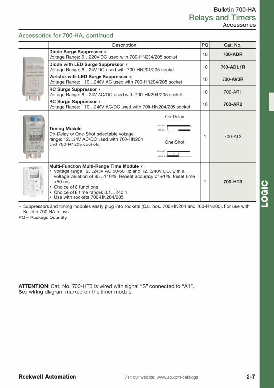
Bulletin 700-HARelays and Timers
2-7Visit our website: www.ab.com/catalogsRockwell Automation
LO
GIC
Accessories for 700-HA, continued
Accessories
ATTENTION: Cat. No. 700-HT3 is wired with signal “S” connected to “A1”.See wiring diagram marked on the timer module.
Description PQ Cat. No.
Diode Surge Suppressor �Voltage Range: 6…220V DC used with 700-HN204/205 socket 10 700-ADR
Diode with LED Surge Suppressor �Voltage Range: 6…24V DC used with 700-HN204/205 socket 10 700-ADL1R
Varistor with LED Surge Suppressor �Voltage Range: 110…240V AC used with 700-HN204/205 socket 10 700-AV3R
RC Surge Suppressor �Voltage Range: 6…24V AC/DC used with 700-HN204/205 socket 10 700-AR1
RC Surge Suppressor �Voltage Range: 110…240V AC/DC used with 700-HN204/205 socket 10 700-AR2
Timing ModuleOn-Delay or One-Shot selectable voltagerange: 12…24V AC/DC used with 700-HN204and 700-HN205 sockets.
On-Delay
1 700-AT3
LED & R
One-Shot
LED & R
Multi-Function Multi-Range Time Module �
� Voltage range 12…240V AC 50/60 Hz and 12…240V DC, with avoltage variation of 85…110%. Repeat accuracy of ±1%. Reset time<50 ms.
� Choice of 8 functions� Choice of 8 time ranges 0.1…240 h� Use with sockets 700-HN204/205
1 700-HT3
� Suppressors and timing modules easily plug into sockets (Cat. nos. 700-HN204 and 700-HN205). For use withBulletin 700-HA relays.
PQ = Package Quantity

Bulletin 700-HCRelays and Timers
2-8 Visit our website: www.ab.com/catalogs Rockwell Automation
LO
GIC
� 10 A Contact Ratings� 2PDT or 4PDT� Standard ON/OFF Flag Indicator� Blade Style Terminals� Choice of Standard Silver Nickel Contacts, or Silver Nickel with Gold
Plated Contacts for Low Energy Applications� Options: LED, Push-to-Test with Manual Override Option� Tungsten UL Approvals
4-Pole: 5A @ 24V DC2-Pole: 10A @ 24V DC
Product Selection
Interposing/Isolation Relays 700-HC
Bulletin 700-HC Miniature Square Base with Blade Terminals
Description Wiring Diagrams Contact Rating Coil Voltage PQ Cat. No. ��
2PDT2-Pole2 Form CContacts:10 A = AgNi Contacts
10 AC300R300
Low energy rating; (10V, 10 mA)
24V AC
1
700-HC22A24-3
240V AC 700-HC22A2-3
Sockets 700-HN103700-HN104 24V DC 700-HC22Z24-3
4PDT4-Pole4 Form CContacts:10A = AgNiContacts
7 ALow energy rating;
(10V, 1 mA)
24V AC
1
700-HC24A24-3
240V AC 700-HC24A2-3
Socket 700-HN104 24V DC 700-HC24Z24-3
Socket Base10 700-HN103
10 700-HN104
� LED option: Add suffix (-4) to the selected 700-HC relay cat. no. except for the 240V AC units, add (-4L).�Push-to-test and LED option: Add suffix (-3-4) to the selected 700-HC relay cat. no., except for the 240V AC
units, add (-3-4L).PQ = Package Quantity

� 8 A/16 A Contact Ratings� DPDT/SPDT� Plug-in Blade Style Terminals� Built-in Retainer Clip in Sockets� Choice of Standard Silver Cadmium Contacts
or Silver with Gold Plated Contacts� Options: LED, Push-to-Test with Manual Override
Option
Bulletin 700-HKRelays and Timers
2-9Visit our website: www.ab.com/catalogsRockwell Automation
LO
GIC
Product Selection
Interposing/Isolation Relays 700-HK
Slim Line Relay with Plug-in Quick Connect Terminations
700-HK SPDT 700-HK DPDT
Description Wiring Diagrams Contact Rating Coil Voltage PQ Cat. No. ��‡
SPDT1-Pole1 Form CAgNi Contacts 16 A
24V AC
1
700-HK36A24
240V AC 700-HK36A2
Socket 700-HN121 24V DC 700-HK36Z24
DPDT2-Pole2 Form CAgNi Contacts 8 A
24V AC
1
700-HK32A24
240V AC 700-HK32A2
Socket 700-HN122 24V DC 700-HK32Z24
Socket Base10 700-HN221
10 700-HN222
� LED option: Add suffix (-4) to the selected Bulletin 700-HK relay cat. no. except for the 240V AC units, add (-4L).�Push-to-test and LED option: Add suffix (-3-4) to the selected Bulletin 700-HC relay cat. no., except for the
240V AC units, add (-3-4L).‡ For AgCdO contact with gold overlay: Replace “3” with “X” in cat. no. For example, if cat. no. 700-HK36A1 is
required with gold overlay, the new catalog number is 700-HKX6A1.PQ = Package Quantity

Bulletin 700-HLRelays and Timers
2-10 Visit our website: www.ab.com/catalogs Rockwell Automation
LO
GIC
Solid State
Assembled Devices Input Voltage Output Type PQCat. No.
(Screw Terminals)
Cat. No.(Spring Clamp
Terminals)
24V DC
SPDT (1 C/O);
Ith = 6A�
10 �♣ 700-HLT1Z24 700-HLT2Z24
24V AC/DC 10 700-HLT1U24 700-HLT2U24
110/125V AC/DC 10 ♣ 700-HLT1U1 700-HLT2U1
220…240V AC/DC 10 700-HLT1U2 700-HLT2U2
Built-in LCSC (leakage currentsuppression circuit)120V AC and 125V DC§
10 � 700-HLT1L1
Built-in LCSC (leakage currentsuppression circuit) 240V AC§ 10 � 700-HLT1L2
SPDT Relays
Product Selection
Terminal Block Relays 700-HL, 1-Pole
� Up to 85% panel space savings vs. traditional relays
� DIN rail mounting� Only 6.2 mm wide (SPDT)� Standard LED, Reverse Polarity Protection
and Surge Protection� Screw Terminals and Spring Clamp Bases
700-HLT… 700-HLS…
Assembled Devices Input Voltage Output Type PQCat. No.
(Screw Terminals)
Cat. No.(Spring Clamp
Terminals)
24V DC
1 N.O. solid-state;
Ith = 2 A, 24V DC‡
10 �♣ 700-HLS1Z24 700-HLS2Z24
220…240V AC/DC 10 � 700-HLS1U2 700-HLS2U2
Built-in LCSC (leakage currentsuppression circuit)120V AC and 125V DC§
10 � 700-HLS1L1
Built-in LCSC (leakage currentsuppression circuit) 240V AC§ 10 � 700-HLS1L2
� For gold-plated contacts: Add the letter “X” at the end of the catalog number. For example: if cat. no. 700-HLT1Z24 is required with gold plating, the new cat. no. is 700-HLT1Z24X.
� Electromechanical relay to solid-state relay interchangeability is possible.‡ Reverse polarity on the output terminals of the solid-state relay will result in the output being "On" regardless of
the state of the input voltage.§ Leakage current suppression up to 2.2 mA off state current.♣ Available as EX version (for US hazardous locations applications only). Add “-EX” at the end of the cat. no.
(Example: 700-HLS1Z24-EX).PQ = Package Quantity

Bulletin 700-HLRelays and Timers
2-11Visit our website: www.ab.com/catalogsRockwell Automation
LO
GIC
Product Selection
� Slim build of only 14mm wide that meets thedemand for panelspace-savings
� Standard built-in reverse DC polarityprotection ensures DC coildevices are notdamaged if improper polarity is connected
� Separation of coil and contact terminals� Snap in marker system� One piece housing construction in terminal area to prevent
screwdriver blade from catching on housing seam� 10 Amp Contact Rating
Assembled Devices Input Voltage Output Type PQCat. No.
(Screw Terminals)
Cat. No.(Spring Clamp
Terminals)
24V DCDPDT
(2 C/O); Ith = 10 A�
10 700-HLT12Z24 700-HLT22Z24
24V AC/DC 10 700-HLT12U24 700-HLT22U24
110/125V AC/DC 10 700-HLT12U1 700-HLT22U1
220…240V AC/DC 10 700-HLT12U2 700-HLT22U2
� For Gold-plated contacts: Add the letter "X" at the end of the catalog number. Example: Cat. No. 700-HLT12Z24with gold plated contacts is catalog number 700-HLT12Z24X. The following relays are available with the gold-plated contact option: 700-HLT_2Z24, 700-HLT_2U24, 700-HLT_2U1, and 700-HLT_2U2.
Terminal Block Relays 700-HL, 2-Pole
DPDT Relays
Accessories for Terminal Block Relays
Description For Use With PQ Cat. No.
Replacement RelaysOrder multiples of 20.
24V AC/DC700-HL(1-Pole) 20
� 700-TBR24
110/125V AC/DC220…240V AC/DC � 700-TBR60
Replacement SSR4-blade miniature relay for usewith 1 N.O. SSR DC output.Order multiples of 20.
24V DC700-HL(1-Pole) 20
700-TBS24
48V DC, 110/125VAC/DC
220…240V AC/DC700-TBS60
Replacement RelaysOrder must be for 20 relays or
multiples of 20.
48V DC
700-HL(2-Pole) 20
700-TBR248
110/125V AC/DC220…240V AC/DC � 700-TBR2110
20-Way JumperCan be cut to required length.Ith = 36 A max per 20-way
jumper.
Red700-HL(1-Pole) 1
700-TBJ20R
Grey 700-TBJ20G
Blue 700-TBJ20B
8-Way JumperCan be cut to required length.Ith = 10 A max per 8-way
jumper.
Red700-HL(2-Pole) 1
700-TBJ08R
Grey 700-TBJ08G
Blue 700-TBJ08B
� For gold-plated contacts: Add the letter “X” at the end of the catalog number. For example: if Cat. No. 700-TBR24 is required with gold plating, the new cat. no. is 700-TBR24X. Gold-plated contacts with surcharge.
�Go to http://www.ab.com/software/termblock/index.html and download software. Create custom text, save file,and e-mail to your local Rockwell Automation office.
Note: Terminal block relay bases are not sold separately.PQ = Package Quantity

Bulletin 700-HPRelays and Timers
2-12 Visit our website: www.ab.com/catalogs Rockwell Automation
LO
GIC
Accessories
� 8 A Contact Ratings� DPDT/ (2 c/o) Contacts� Plug-in PIN Style (PCB) Terminals (5 mm Pinning)� Choice of Standard Silver Nickel Contacts, or Silver Nickel with Gold
Plated ContactsOptions: None
Product Selection
"Pin Style” Relays 700-HP (PCB)
Slim Line Relay with "PIN Style" Terminations
Description Wiring Diagram Contact Rating Coil Voltage PQ Cat. No.
DPDT2-Pole2 Form CAgNi + Au Gold Plated Contacts
8 A
24V AC 10 700-HPX2A24
240V AC 10 700-HPX2A2
24V DC 10 700-HPX2Z24
DPDT2-Pole2 Form CAgNi Contacts
24V AC 10 700-HP32A24
240V AC 10 700-HP32A2
Socket 700-HN123 24V DC 10 700-HP32Z24
PQ = Package Quantity
Description PQ Cat. No.
Diode Surge Suppressor �Voltage Range: 6…220V DC used with 700-HN204/205 socket 10 700-ADR
Diode with LED Surge Suppressor �Voltage Range: 6…24V DC used with 700-HN204/205 socket 10 700-ADL1R
Varistor with LED Surge Suppressor �Voltage Range: 110…240V AC used with 700-HN204/205 socket 10 700-AV3R
RC Surge Suppressor �Voltage Range: 6…24V AC/DC used with 700-HN204/205 socket 10 700-AR1
RC Surge Suppressor �Voltage Range: 110…240V AC/DC used with 700-HN204/205 socket 10 700-AR2
Timing ModuleOn-Delay or One-Shot selectable voltagerange: 12…24V AC/DC used with 700-HN204and 700-HN205 sockets.
On-Delay
1 700-AT3
LED & R
One-Shot
LED & R
Screw Terminal Socket — Panel or DIN Rail Mounting8-pin miniature socket for use with 2-pole, Bulletin 700-HP relays.Incorporates coil and contact separation.
10 700-HN123
PQ = Package Quantity

Bulletin 700-FERelays and Timers
2-13Visit our website: www.ab.com/catalogsRockwell Automation
LO
GIC
� Adjustable Function and Timing Range Timing Relays� DIN Rail Mounted Without Cost of Socket� 17.5 mm wide, Multi-Function or Single Function� Available as 1 N.O. or SPDT Contact Output, 5A� Timing Ranges From 0.05s…10.0h
Economy Timing Relays 700-FE
Single-Function
Product Selection
This device offers you one specific timing function.
Operating Mode Contact Output Timing Range Input Voltage Cat. No.
ON-delay1 N.O. 0.05 s…10 hr
(6 settings) §24V AC/DC *
110…240V AC 50/60 Hz � 700-FEA1TU22
SPDT (1 C/O) 0.05 s…10 hr(6 settings) ‡
24V…48V AC/DC24…240V AC 50/60 Hz 700-FEA3TU23
OFF-delay1 N.O. 0.05 s…10 hr
(6 settings) §24V AC/DC *
110…240V AC 50/60 Hz � 700-FEB1TU22
SPDT (1 C/O) 0.05 s…10 hr(6 settings) ‡
24V…48V AC/DC24…240V AC 50/60 Hz 700-FEB3TU23
One Shot1 N.O. 0.05 s…10 hr
(6 settings) §24V AC/DC *
110…240V AC 50/60 Hz � 700-FED1TU22
SPDT (1 C/O) 0.05 s…10 hr(6 settings) ‡
24V…48V AC/DC24…240V AC 50/60 Hz 700-FED3TU23
Fleeting OFF-delay SPDT (1 C/O) 0.05 s…10 hr(6 settings) ‡
24V…48V AC/DC24…240V AC 50/60 Hz 700-FEE3TU23
Flasher (repeatcycle starting withpulse)
1 N.O. 0.05 s…10 hr(6 settings) §
24V AC/DC *110…240V AC 50/60 Hz � 700-FEF1TU22
SPDT (1 C/O) 0.05 s…10 hr(6 settings) ‡
24V…48V AC/DC24…240V AC 50/60 Hz 700-FEF3TU23
Pulse Converter SPDT (1 C/O) 0.05 s…10 hr(6 settings) ‡
24V…48V AC/DC24…240V AC 50/60 Hz 700-FEL3TU23
� Voltage is either 24V AC 50/60 Hz or 24V DC.‡ Time ranges: 0.05 s…1 s, 0.5…10 s, 0.05…1 min., 0.5…10 min, 0.05…1 h, 0.5…10 h.§ Time ranges: 0.75…15 s, 3…60 s, 0.4…8 min., 3…60 min.
Multi-FunctionThis device offers you the flexibility of selecting one of 4 single timing functions.
Operating Mode Contact Output Timing Range Input Voltage Cat. No.
ON-delay, OFF-delay,One Shot, Flasher(repeat cycle startingwith pulse)
1 N.O. 0.05 s…10 hr(6 settings) �
24V AC/DC *110…240V AC
50/60 Hz �700-FEM1RU22
SPDT (1 C/O) 0.05 s…10 hr(6 settings) �
24V…48V AC/DC24…240V AC
50/60 Hz700-FEM3TU23
� Voltage is either 24V AC or 24V DC 50/60 Hz.� Time ranges: 0.5 s…10 s, 3…60 s, 0.5 s…10 min., 3…60 min.
Special Functions
Operating Mode Contact Output Timing Range Input Voltage Cat. No.
Star-Delta 2 N.O. with 1Common
0.15 s…10 min(4 settings) ♣
24V…48V AC/DC24…240V AC 50/60 Hz 700-FEY2QU23
♣ Time ranges: (3s) 0.15…3 s, (10s) 0.5…10 s, (1m) 0.05…1 min, (10m) 0.5…10 min
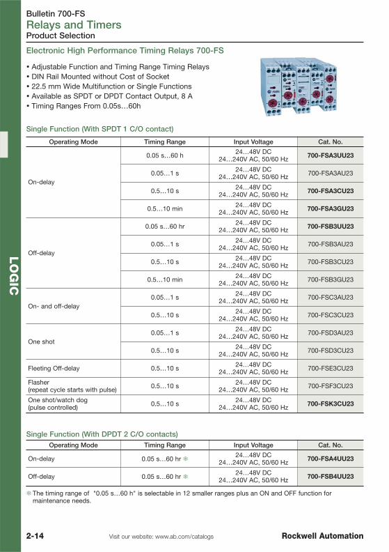
Bulletin 700-FSRelays and Timers
2-14 Visit our website: www.ab.com/catalogs Rockwell Automation
LO
GIC
� Adjustable Function and Timing Range Timing Relays� DIN Rail Mounted without Cost of Socket� 22.5 mm Wide Multifunction or Single Functions� Available as SPDT or DPDT Contact Output, 8 A� Timing Ranges From 0.05s…60h
Product Selection
Electronic High Performance Timing Relays 700-FS
Single Function (With SPDT 1 C/O contact)
Single Function (With DPDT 2 C/O contacts)Operating Mode Timing Range Input Voltage Cat. No.
On-delay 0.05 s…60 hr �24…48V DC
24…240V AC, 50/60 Hz 700-FSA4UU23
Off-delay 0.05 s…60 hr �24…48V DC
24…240V AC, 50/60 Hz 700-FSB4UU23
� The timing range of "0.05 s…60 h" is selectable in 12 smaller ranges plus an ON and OFF function formaintenance needs.
Operating Mode Timing Range Input Voltage Cat. No.
On-delay
0.05 s…60 h 24…48V DC24…240V AC, 50/60 Hz 700-FSA3UU23
0.05…1 s 24…48V DC24…240V AC, 50/60 Hz 700-FSA3AU23
0.5…10 s 24…48V DC24…240V AC, 50/60 Hz 700-FSA3CU23
0.5…10 min 24…48V DC24…240V AC, 50/60 Hz 700-FSA3GU23
Off-delay
0.05 s…60 hr 24…48V DC24…240V AC, 50/60 Hz 700-FSB3UU23
0.05…1 s 24…48V DC24…240V AC, 50/60 Hz 700-FSB3AU23
0.5…10 s 24…48V DC24…240V AC, 50/60 Hz 700-FSB3CU23
0.5…10 min 24…48V DC24…240V AC, 50/60 Hz 700-FSB3GU23
On- and off-delay0.05…1 s 24…48V DC
24…240V AC, 50/60 Hz 700-FSC3AU23
0.5…10 s 24…48V DC24…240V AC, 50/60 Hz 700-FSC3CU23
One shot0.05…1 s 24…48V DC
24…240V AC, 50/60 Hz 700-FSD3AU23
0.5…10 s 24…48V DC24…240V AC, 50/60 Hz 700-FSD3CU23
Fleeting Off-delay 0.5…10 s 24…48V DC24…240V AC, 50/60 Hz 700-FSE3CU23
Flasher (repeat cycle starts with pulse) 0.5…10 s 24…48V DC
24…240V AC, 50/60 Hz 700-FSF3CU23
One shot/watch dog (pulse controlled) 0.5…10 s 24…48V DC
24…240V AC, 50/60 Hz 700-FSK3CU23
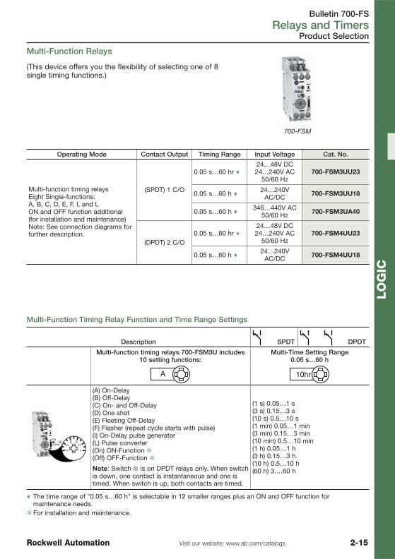
Bulletin 700-FSRelays and Timers
2-15Visit our website: www.ab.com/catalogsRockwell Automation
LO
GIC
Product Selection
Multi-Function Relays
(This device offers you the flexibility of selecting one of 8single timing functions.)
700-FSM
Operating Mode Contact Output Timing Range Input Voltage Cat. No.
Multi-function timing relaysEight Single-functions:A, B, C, D, E, F, I, and LON and OFF function additional(for installation and maintenance)Note: See connection diagrams forfurther description.
(SPDT) 1 C/O
0.05 s…60 hr �24…48V DC24…240V AC
50/60 Hz700-FSM3UU23
0.05 s…60 h � 24…240VAC/DC 700-FSM3UU18
0.05 s…60 h � 346…440V AC50/60 Hz 700-FSM3UA40
(DPDT) 2 C/O0.05 s…60 hr �
24…48V DC24…240V AC
50/60 Hz700-FSM4UU23
0.05 s…60 h � 24…240VAC/DC 700-FSM4UU18
Multi-Function Timing Relay Function and Time Range Settings
Description SPDT DPDT
Multi-function timing relays 700-FSM3U includes10 setting functions:
Multi-Time Setting Range 0.05 s…60 h
A 10hr
(A) On-Delay(B) Off-Delay(C) On- and Off-Delay(D) One shot(E) Fleeting Off-Delay(F) Flasher (repeat cycle starts with pulse)(I) On-Delay pulse generator(L) Pulse converter(On) ON-Function �(Off) OFF-Function �
(1 s) 0.05…1 s(3 s) 0.15…3 s(10 s) 0.5…10 s(1 min) 0.05…1 min(3 min) 0.15…3 min(10 min) 0.5…10 min(1 h) 0.05…1 h(3 h) 0.15…3 h(10 h) 0.5…10 h(60 h) 3.…60 hNote: Switch ⊗ is on DPDT relays only. When switch
is down, one contact is instantaneous and one istimed. When switch is up, both contacts are timed.
� The time range of "0.05 s…60 h" is selectable in 12 smaller ranges plus an ON and OFF function formaintenance needs.
� For installation and maintenance.

Bulletin 700-FSRelays and Timers
2-16 Visit our website: www.ab.com/catalogs Rockwell Automation
LO
GIC
Operating Mode Contact Output Timing Range Input Voltage Cat. No.
Flasher (Repeat Cycle Starting withPulse or Pause) (SPDT) 1 C/O
0.05 s…60 h �24…48V DC24…240V AC
50/60 Hz700-FSH3UU23
2 x 0.05 s…60 h(2 ranges)
24…48V DC24…240V AC,
50/60 Hz700-FSH3VU23
OFF-delay without supply voltages(True OFF-delay) ‡ (SPDT) 1 C/O
0.15 s…10 min�
24…240V DC24…240V AC
50/60 Hz
700-FSQ3QU18
OFF-delay without supply voltages(True OFF-delay) ‡ (DPDT) 2 C/O 700-FSQ4QU18
Star-Delta 2 N.O. + 1Common
0.5 s…10 s
24...48V DC24...240V AC
50/60 Hz
700-FSY2CU23
1.5…30 s 700-FSY2DU23
0.05 s…1 min 700-FSY2EU23
0.15…3 min 700-FSY2FU23
0.5…10 min 700-FSY2GU23
0.5 s…10 s
346…440V AC50/60 Hz
700-FSY2CA40
1.5…30 s 700-FSY2DA40
0.05 s…1 min. 700-FSY2EA40
0.15…3 min. 700-FSY2FA40
� The timing range of "0.05 s…60 h" is selectable in 12 smaller ranges plus an ON and OFF function formaintenance needs.
� This timing range is selectable in four smaller ranges: 0.15 s…2.5 s, 0.5 s…10 s, 4 s…80 s, 30 s…10 min.‡ Due to shock during shipment, the state of the contacts should be verified before initial use.
Product Selection
Special Function Relays
700-FSH 700-FSY
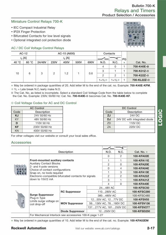
Bulletin 700-KRelays and Timers
2-17Visit our website: www.ab.com/catalogsRockwell Automation
LO
GIC
� IEC Compact Industrial Relay� IP2X Finger Protection� Bifurcated Contacts for low level signals� Optional integrated coil protection diode
Miniature Control Relays 700-K
AC / DC Coil Voltage Control Relays
AC-12 AC-15 (A600) Contacts
PQ� Cat. No.
Ie [A] Ie [A]
40 °C 60 °C 24/48V 230V 400V 500V 690V N.O. N.C.
10 6 3 2 1.2 1 0.6
4 0 1 700-K40E-⊗⊗
3 1 1 700-K31Z-⊗
2 2 1 700-K22Z-⊗
1+1L� 1+1L� 1 700-KL22Z-⊗
� May be ordered in package quantities of 20. Add letter M to the end of the cat. no. Example: 700-K40E-KFM.� 1L = Late break N.C./early make N.O.⊗ The Cat. No. as listed is incomplete. Select a standard Coil Voltage Code from the table below to complete the Cat. No. Example: 230V, 50/60 Hz: Cat. No. 700-K40E-⊗ becomes Cat. No. 700-K40E-KF.
⊗ Coil Voltage Codes for AC and DC Control
AC Control DC ControlCode Description Code Description
KJ 24V 50/60 Hz ZJ 24V DCKY 48V 50/60 Hz DJ 24V DC with integrated diodeD 110V 50 Hz ZD 110V DC
KF 230V 50/60 Hz ZA 220V DCKN 400V 50/60 Hz
For other voltages visit our website or consult your local sales office.
Accessories
Description Cat. No. �N.O. N.C.
Front-mounted auxiliary contactsAuxiliary Contact Blocks 2- and 4-pole versionsChoice of contact configurationsSnap on, no tools requiredElectronic-compatible bifurcated contacts for signalsdown to 15V/2 mA
0 2 100-KFA02E
1 1 100-KFA11E2 0 100-KFA20E0 4 100-KFA04E1 3 100-KFA13E2 2 100-KFA22Z3 1 100-KFA31Z4 0 100-KFA40E
Surge SuppressorPlug-in TypeLimits surge voltage oncoil drop-off
RC Suppressor24…48V AC 100-KFSC50
110…280V AC 100-KFSC280380…480V AC 100-KFSC480
MOV Suppressor12…55V AC, 12…77V DC 100-KFSV55
56…136V AC, 78…180V DC 100-KFSV136137…277V AC, 181…250V DC 100-KFSV277
Diode Suppressor 12…250V DC 100-KFSD250For Mechanical Interlock see accessories 100-K page 1-27
� May be ordered in package quantities of 10. Add letter M to the end of the cat. no. Example: 100-KFA02EM
Product Selection / Accessories
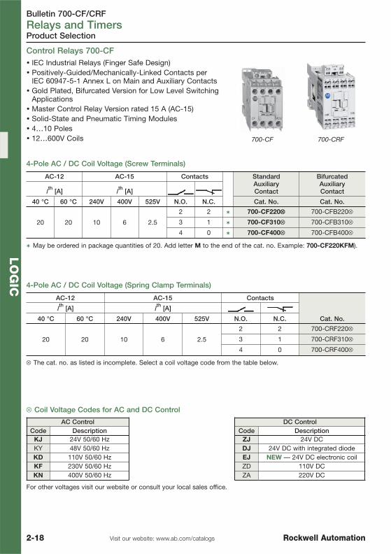
Bulletin 700-CF/CRFRelays and Timers
2-18 Visit our website: www.ab.com/catalogs Rockwell Automation
LO
GIC
� IEC Industrial Relays (Finger Safe Design)� Positively-Guided/Mechanically-Linked Contacts per
IEC 60947-5-1 Annex L on Main and Auxiliary Contacts� Gold Plated, Bifurcated Version for Low Level Switching
Applications� Master Control Relay Version rated 15 A (AC-15)� Solid-State and Pneumatic Timing Modules� 4…10 Poles� 12…600V Coils
Control Relays 700-CF
Product Selection
700-CF 700-CRF
AC-12 AC-15 Contacts StandardAuxiliaryContact
BifurcatedAuxiliaryContactI
th [A] Ith [A]
40 °C 60 °C 240V 400V 525V N.O. N.C. Cat. No. Cat. No.
20 20 10 6 2.5
2 2 � 700-CF220⊗⊗ 700-CFB220⊗
3 1 � 700-CF310⊗ 700-CFB310⊗
4 0 � 700-CF400⊗ 700-CFB400⊗
� May be ordered in package quantities of 20. Add letter M to the end of the cat. no. Example: 700-CF220KFM).
4-Pole AC / DC Coil Voltage (Spring Clamp Terminals)
AC-12 AC-15 Contacts
Cat. No.
Ith [A] I
th [A]
40 °C 60 °C 240V 400V 525V N.O. N.C.
20 20 10 6 2.5
2 2 700-CRF220⊗
3 1 700-CRF310⊗
4 0 700-CRF400⊗
⊗ The cat. no. as listed is incomplete. Select a coil voltage code from the table below.
⊗ Coil Voltage Codes for AC and DC Control
AC Control DC ControlCode Description Code Description
KJ 24V 50/60 Hz ZJ 24V DCKY 48V 50/60 Hz DJ 24V DC with integrated diodeKD 110V 50/60 Hz EJ NEW — 24V DC electronic coilKF 230V 50/60 Hz ZD 110V DCKN 400V 50/60 Hz ZA 220V DC
For other voltages visit our website or consult your local sales office.
4-Pole AC / DC Coil Voltage (Screw Terminals)

Bulletin 700-CF/CRFRelays and Timers
2-19Visit our website: www.ab.com/catalogsRockwell Automation
LO
GIC
Auxiliary Contacts for 700-CF, 700-CRF �
Description For Use With Cat. No.N.O. N.C.
Auxiliary Contacts with Screw Terminals �
Auxiliary Contact Blocks for FrontMounting2- and 4-poleQuick and easy mounting without toolsElectronically-compatible contacts downto 17V, 5 mAMechanically linked performance betweenN.O. and N.C. poles and to the maincontactor poles (except for L types)Models with equal function with severalterminal numbering choices1L = Late break N.C./early make N.O.Bifurcated versions for switching lowenergy circuits are also available ‡
0 2
700-CF
100-FA02
1 1 100-FA11
2 0 100-FA20
2 2 100-FA22
3 1 100-FA31
4 0 100-FA40
1+1L 1+1L 100-FAL22
Auxiliary Contacts with Spring Clamp Terminals
Auxiliary Contact Blocks for FrontMounting2- and 4-poleQuick and easy mounting without toolsElectronic-compatible contacts down to17V, 5 mAMechanically linked performance betweenN.O. and N.C. poles and to the maincontactor poles (except for L types)Models with equal function with severalterminal numbering choices1L = Late break N.C./early make N.O.Bifurcated version for switching down to5V, 3 mA ‡
0 2
700-CRF
100-CRFA02
1 1 100-CRFA11
2 0 100-CRFA20
2 2 100-CRFA22
3 1 100-CRFA31
4 0 100-CRFA40
1+1L 1+1L 100-CRFAL22
� Max. number of auxiliary contacts that may be mounted:AC coil contactors — max. 4 N.O. contacts on the front of the contactor, 2 N.O. contacts on the side, 4 N.C. front or side, 6 total.DC coil contactors — max. 4 N.O. contacts on the front of the contactor or max 2 N.O. contacts on the side, 4 N.C. front or side, 4 total.
�May be ordered in package quantities of 10. Add letter M to the end of the cat. no. (Example: 100-FA02M).‡ Selection data, see catalog A11_ or consult your local sales office.
Accessories
Additional Accessories for 700-CF, 700-CRF see page 1-31

Bulletin 700-SSolid State Devices
2-20 Visit our website: www.ab.com/catalogs Rockwell Automation
LO
GIC
Product Line Overview
Bulletin 700-SH
Type Hockey Puck
Features Panel/DIN Mount, High Current, Protective Cover, LED Status
Load Type AC (47…63 Hz)3…60V DC
Load VoltageRange
3…50V DC, 24…265V AC42…530V AC, 42…265V AC,
42…660V AC
Load Current Max.(Continuous) 10 A/100 A �
Max LeakageCurrent to Load <3 mA
Zero Cross LoadSwitching Yes
EquivalentElectromechanicalRelay ContactArrangement
1 N.O.Form A
Rated Control(Input) Voltage
3…32V DC, 4…32V DC,80…130V AC, 20…260V AC20…280V AC/22…48V DC
LED Indicator Yes
Mounting Method Panel without heat sink, Panel or DIN with heat sink
Dielectric Strength >4000V AC RMS
Certification cURus, CE , CSA
Max. AmbientOperatingTemperature
-20…70 °C (no condensation)
Product Selection See page 2-21
Solid State Devices 700-SH
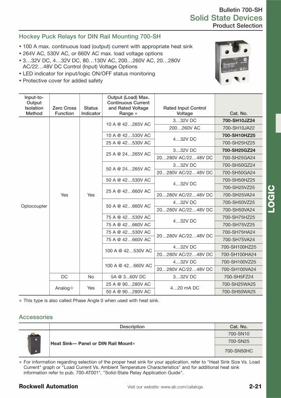
Bulletin 700-SHSolid State Devices
2-21Visit our website: www.ab.com/catalogsRockwell Automation
LO
GIC
Product Selection
� 100 A max. continuous load (output) current with appropriate heat sink� 264V AC, 530V AC, or 660V AC max. load voltage options� 3…32V DC, 4…32V DC, 80…130V AC, 200…260V AC, 20…280V
AC/22…48V DC Control (Input) Voltage Options� LED indicator for input/logic ON/OFF status monitoring� Protective cover for added safety
Accessories
Hockey Puck Relays for DIN Rail Mounting 700-SH
Input-to-Output
IsolationMethod
Zero CrossFunction
StatusIndicator
Output (Load) Max.Continuous Currentand Rated Voltage
Range �Rated Input Control
Voltage Cat. No.
Optocoupler
Yes Yes
10 A @ 42…265V AC3…32V DC 700-SH10JZ24
200…260V AC 700-SH10JA22
10 A @ 42…530V AC4…32V DC
700-SH10HZ25
25 A @ 42…530V AC 700-SH25HZ25
25 A @ 24…265V AC3…32V DC 700-SH25GZ24
20…280V AC/22…48V DC 700-SH25GA24
50 A @ 24…265V AC3…32V DC 700-SH50GZ24
20…280V AC/22…48V DC 700-SH50GA24
50 A @ 42…530V AC4…32V DC
700-SH50HZ25
25 A @ 42…660V AC700-SH25VZ25
20…280V AC/22…48V DC 700-SH25VA24
50 A @ 42…660V AC4…32V DC 700-SH50VZ25
20…280V AC/22…48V DC 700-SH50VA24
75 A @ 42…530V AC4…32V DC
700-SH75HZ25
75 A @ 42…660V AC 700-SH75VZ25
75 A @ 42…530V AC20…280V AC/22…48V DC
700-SH75HA24
75 A @ 42…660V AC 700-SH75VA24
100 A @ 42…530V AC4…32V DC 700-SH100HZ25
20…280V AC/22…48V DC 700-SH100HA24
100 A @ 42…660V AC4…32V DC 700-SH100VZ25
20…280V AC/22…48V DC 700-SH100VA24
DC No 5A @ 3...60V DC 3…32V DC 700-SH5FZ24
Analog� Yes25 A @ 90…280V AC
4…20 mA DC700-SH25WA25
50 A @ 90…280V AC 700-SH50WA25
� This type is also called Phase Angle 0 when used with heat sink.
Description Cat. No.
Heat Sink— Panel or DIN Rail Mount�
700-SN10
700-SN25
700-SN50HC
� For information regarding selection of the proper heat sink for your application, refer to "Heat Sink Size Vs. LoadCurrent" graph or "Load Current Vs. Ambient Temperature Characteristics" and for additional heat sinkinformation refer to pub. 700-AT001*, "Solid-State Relay Application Guide".

Bulletin 900-TCTemperature Controllers
2-22 Visit our website: www.ab.com/catalogs Rockwell Automation
LO
GIC
Product Line Overview
Temperature Controllers 900-TC
Bulletin 900-TC8 900-TC16 900-TC32
Dimensions:HeightWidthDepth
96 mm48 mm78 mm
48 mm48 mm78 mm
24 mm48 mm100 mm
Sample Rate 250 or 500 ms 500 ms
Indication Accuracy ±0.5% PV ±1 digit max.
Heating/CoolingControl Mode � � �
Control Method ON/OFF or 2-PID (auto-tune and self-tune) with time proportioning ON/OFF output
Inputs
• Thermocouple Input• Platinum Resistance Temperature Sensor• Analog Input 0…20 mA, 4…20 mA / 1…5V DC, 0…5V DC, 0…10V DC, 0…50mV DC�
• Non-Contact Temperature Sensor
Control Output 1
• Relay Output (electromechanical)• Voltage Output for Solid-State Relay• Triac Output (AC only)• Analog Output 4…20 mA and 0…20 mA
• Relay Output (electromechanical)
• Voltage Output for Solid-State Relay
Control Output 2• Voltage Output for
Solid-State Relay• Triac Output (AC only)
• Voltage Output for Solid-State Relay (with optionunit)
—
Max. Number of Alarms 3 2 (with option unit) 1
RS-232CCommunicationsFunction
� (with option unit) — —
RS-485CommunicationsFunction
� (with option unit) � (with option unit) �
Event Input � (with option unit) � (with option unit) —
Run/Stop via Keypad orInterrupts � � Keypad
Multiple SP SelectionviaKeypad or Interrupts
� � Keypad
Heater Burnout andHeater Short Alarm � � —
Product Selection See Publication 900-SG001… or visit our website: www.ab.com/catalogs
� 900-TC32 only available with 0…50 mV DC.
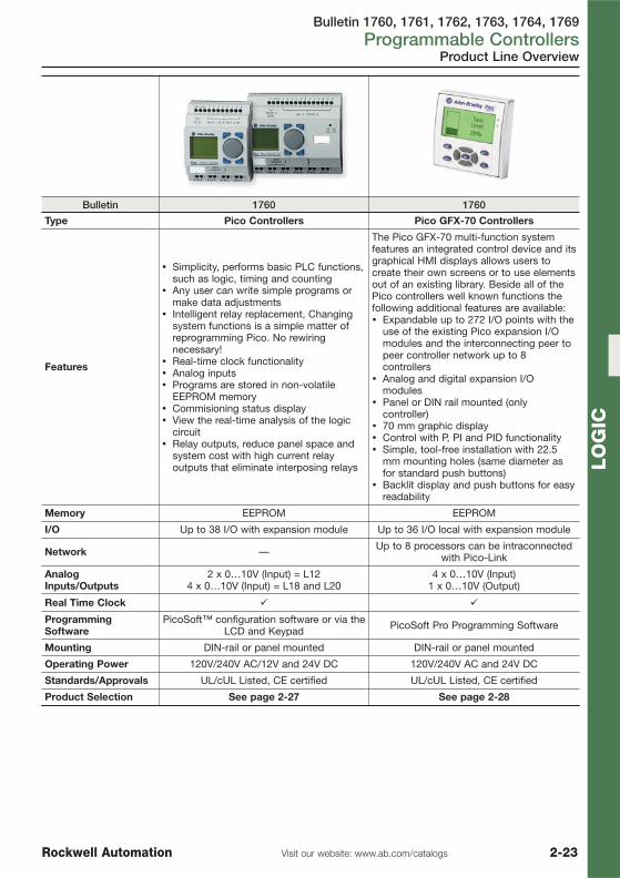
Bulletin 1760, 1761, 1762, 1763, 1764, 1769Programmable Controllers
2-23Visit our website: www.ab.com/catalogsRockwell Automation
LO
GIC
Bulletin 1760 1760
Type Pico Controllers Pico GFX-70 Controllers
Features
� Simplicity, performs basic PLC functions,such as logic, timing and counting
� Any user can write simple programs ormake data adjustments
� Intelligent relay replacement, Changingsystem functions is a simple matter ofreprogramming Pico. No rewiringnecessary!
� Real-time clock functionality� Analog inputs� Programs are stored in non-volatile
EEPROM memory� Commisioning status display� View the real-time analysis of the logic
circuit� Relay outputs, reduce panel space and
system cost with high current relayoutputs that eliminate interposing relays
The Pico GFX-70 multi-function systemfeatures an integrated control device and itsgraphical HMI displays allows users tocreate their own screens or to use elementsout of an existing library. Beside all of thePico controllers well known functions thefollowing additional features are available:� Expandable up to 272 I/O points with the
use of the existing Pico expansion I/Omodules and the interconnecting peer topeer controller network up to 8controllers
� Analog and digital expansion I/Omodules
� Panel or DIN rail mounted (onlycontroller)
� 70 mm graphic display� Control with P, PI and PID functionality� Simple, tool-free installation with 22.5
mm mounting holes (same diameter asfor standard push buttons)
� Backlit display and push buttons for easyreadability
Memory EEPROM EEPROM
I/O Up to 38 I/O with expansion module Up to 36 I/O local with expansion module
Network — Up to 8 processors can be intraconnectedwith Pico-Link
AnalogInputs/Outputs
2 x 0…10V (Input) = L124 x 0…10V (Input) = L18 and L20
4 x 0…10V (Input)1 x 0…10V (Output)
Real Time Clock � �
ProgrammingSoftware
PicoSoft™ configuration software or via theLCD and Keypad PicoSoft Pro Programming Software
Mounting DIN-rail or panel mounted DIN-rail or panel mounted
Operating Power 120V/240V AC/12V and 24V DC 120V/240V AC and 24V DC
Standards/Approvals UL/cUL Listed, CE certified UL/cUL Listed, CE certified
Product Selection See page 2-27 See page 2-28
Product Line Overview

Bulletin 1760, 1761, 1762, 1763, 1764, 1769Programmable Controllers
2-24 Visit our website: www.ab.com/catalogs Rockwell Automation
LO
GIC
Product Line Overview
Bulletin 1761 1763 1762Type MicroLogix 1000 MicroLogix 1100 MicroLogix 1200Memory
User Program/Data Space 1K 4K / 4K 4K / 2K (max)configurable
Data Logging/Recipe Storage — 128k bytes / 64k bytes —
Back-up Memory Module Through hand-heldprogrammer � �
EEPROM Back-up � — —Battery Back-up — � —Flash Back-up — — �I/OUp to 32 Embedded With embedded I/O modules Embedded
Up to 128 — Up to 80 I/O with embedded I/O modules
With embedded I/Omodules
Additional Functionality
Analog Embedded 2 embedded Analog Inputs0…10V Expansion
Trim Potentiometers — 2 digital 2PID — � �High-Speed Counter(24V DC input) 1 @ 6.6 kHz 1 @ 40 kHz 1 @ 20 kHz
Real Time Clock — � �Simple Motion: Pulse WidthModulated/Pulse Train Outp. — 2 @ 40 kHz 1 @ 20 kHz
Single Axis Servo Control — Through embedded PTO Through embedded PTOData Access Tool — Embedded LCD —Floating Point Math — � �Programming SoftwareWindows® - RSLogix 500 &RSLogix 500 Starter � � �
CommunicationsOnline Editing — � —
RS-232 Ports (1) - 8-pin Mini DIN (1) - 8-pin Mini DIN(combo with RS-485 port)
(1) - 8-pin Mini DIN(1) - 8-pin Mini DIN (R)
RS-485 Ports — (1) - 8-pin Mini DIN(combo with RS-232 port) —
DeviceNet Peer to Peer/Slave With 1761-NET-DNI With 1761-NET-DNI With 1761-NET-DNI
Ethernet With 1761-NET-ENI Built-in 10/100 MbpsEtherNet/IP Port With 1761-NET-ENI
DH-485 With 1761-NET-AIC With 1761-NET-AIC With 1761-NET-AICDF1 Half-DuplexMaster/Slave Slave only � �
SCADA RTU - Modbus RTU — Master/Slave Master/SlaveASCII — � �
Operating Power 120/240V AC / 24V DC 120/240V AC / 24V DC /12…24V DC 120/240V AC / 24V DC
Standards/Approvals UL, CSA or C-UL, CE, Class I Div. 2Product Selection See page 2-29 See page 2-30 See page 2-31

Bulletin 1760, 1761, 1762, 1763, 1764, 1769Programmable Controllers
2-25Visit our website: www.ab.com/catalogsRockwell Automation
LO
GIC
Product Line Overview
Bulletin 1766 1764-LSP 1764-LRPType MicroLogix™ 1400 MicroLogix™ 1500Memory
User Program/Data Space 10K/10K configurable 3.6K/4K (max)configurable
10K/4K (max)configurable
Data Logging/Recipe Storage 128kB/� Recipe: up to 64kB Recipe: User Programmemory 48 kB
EEPROM Backup — — —Battery Backup � � �Backup Memory Module � � �I/OUp to 32 Embedded Embedded w/Loc. Exp.
Up to 128 Embedded w/Loc. Exp. upto 144 Embedded w/Loc. Exp.
Up to 256 — Embedded w/Loc. Exp.> 256 — Local & Networked Expansion using 1769-SDNAdditional FunctionalityAnalog Embedded Expansion Trim Potentiometers 2 digital 2 2PID � � �High-Speed Counter(24V DC inputs) Up to 6 @ 100kHz 2 @ 20 kHz
Real Time Clock � � �Simple Motion: Pulse WidthModulated/Pulse Train Outp.
3 PTO @ 100 kHz/ PWM @40 kHz 2 @ 20 kHz (DC FET version)
Single Axis Servo Control Through embedded PTO Through embedded PTO (FET)Data Access Tool Embedded LCD � �Floating Point Math � � �Programming SoftwareWindows® - RSLogix™ 500,RSLogix™ 500 Starter &RSLogix™ Micro
� � �
Communications
RS-232 Ports
(1) 9-Pin D-Shell(1) 8-pin Mini DIN
(isolated - combo withRS-485 port)
(1) 8-pin Mini DIN (1) 8-pin Mini DIN & (1)isolated 9-pin D-shell
RS-485 Ports (1) 8-pin Mini DIN (isolated -combo with RS-232 port) — —
DeviceNet Peer to Peer/Slave w/1761-NET-DNI w/ 1761-NET-DNIDeviceNet Scanner — w/ 1769-SDN
Ethernet Built-in 10/100 MbpsEtherNet I/P port w/ 1761-NET-ENI
DH-485 Directly from combo port orusing 1761-NET-AIC w/ 1761-NET-AIC
DF1 Half-DuplexMaster/Slave Radio Modem � � �
Modbus RTU Master/Slave Master/SlaveASCII � � �Operating Power120/240V AC / 24V DC � � �
Certifications cULus Listed, CE, Class IDiv. 2 cULus Listed, CE, Class I Div. 2
Product Selection Page 2-33 Page 2-34 Page 2-34
� Recipe memory size is subtracted from the available data logging memory size

Bulletin 1760, 1761, 1762, 1763, 1764, 1769Programmable Controllers
2-26 Visit our website: www.ab.com/catalogs Rockwell Automation
LO
GIC
Product Line Overview
Bulletin 1769
Type Compact I/OExpansion I/O for MicroLogix 1500
Features
� Unique, compact, modular, rackless design allowing front insertion and removal of themodules on DIN rail with easy to operate latches
� Easy change-out of modules due to unique patented bus connector� Removable terminal blocks with finger-safe covers� Individual point diagnostic LED's for ease of troubleshooting� Software keying to prevent incorrect placing of module within the system� DeviceNet network adapter supporting AutoBaud and Auto Device replacement� ODVA conformance ensures high level of interoperability with other DeviceNet
products� DeviceNet scanner for cost effective OEM solutions
I/O Wide selection of I/O'sUp to 30 modules per node
AnalogInputs/Outputs 4/2/6/8 (Voltage & current, RTD, Thermocouple)
Software RSNetworx for DeviceNet
Mounting Horizontal Panel or DIN rail mounted
Operating Power 120V AC / 240V AC / 24V DC
Standards/Approvals UL/cUL Listed, CE certified
Product Selection See Publication1769-SG002…

Bulletin 1760Programmable Controllers
2-27Visit our website: www.ab.com/catalogsRockwell Automation
LO
GIC
Controllers
Pico Controllers
Product Selection
Line Power Inputs Outputs Analog InputsReal-Time
ClockDisplay and
Keypad Cat. No.
120/240VAC
8(120/240V AC) 4 (relay) ‡ No
Yes Yes 1760-L12AWA
No Yes 1760-L12AWA-NCYes No 1760-L12AWA-ND
12(120/240V AC) 6 (relay) ‡ No
Yes Yes ♣ 1760-L18AWA-EXYes No ♣ 1760-L18AWA-EXND
24V AC
8 �(24V AC) 4 (relay) No
Yes Yes 1760-L12NWNYes No 1760-L12NWN-ND
12(24V AC/24 V
DC)6 (relay) No
Yes Yes ♣ 1760-L18NWN-EX
Yes No ♣ 1760-L18NWN-EXND
12V DC
8 �(12V DC) 4 (relay) 2
(0…10V DC) §Yes Yes 1760-L12DWDYes No 1760-L12DWD-ND
12 �(12V DC)
4 (relay) 2 (0…10V DC) §
Yes Yes ♣ 1760-L18DWD-EX4 (relay) ‡ Yes No ♣ 1760-L18DWD-EXND
24V DC
8 �(24V DC)
4 (transistor) 2 (0…10V DC) §
Yes Yes 1760-L12BBB4 (transistor) Yes No 1760-L12BBB-ND
8 �(24V DC) �
4 (relay) ‡ 2 (0…10V DC) §
Yes Yes 1760-L12BWB
8 �(24V DC)
No Yes 1760-L12BWB-NCYes No 1760-L12BWB-ND
12 �(24V DC)
6 (relay) ‡ Yes Yes ♣ 1760-L18BWB-EX6 (relay) Yes No ♣ 1760-L18BWB-EXND
8 (transistor)Yes Yes ♣ 1760-L20BBB-EXYes No ♣ 1760-L20BBB-EXND
� Two of the digital dc inputs can alternately be used as 0 to 10V dc analog inputs. These inputs can be used aseither digital or analog, not both. For example, you could use 2 analog inputs plus 10 digital inputs on the 1760-L18DWD-EX.
�Current sinking.‡ Isolated.
§ Two digital inputs maybe used for analog.♣ EX = suitable for use with expansion modules.
Expansion Modules
Input Voltage Category Inputs Outputs Cat. No.
120/240V AC 12 (120/240V AC) 6 (relay) � § 1760-IA12XOW6I
24V DC 12 (24V DC) � 8 (transistor) ‡ § 1760-IB12XOB8
24V DC 12 (24V DC) 6 (relay) � 1760-IB12XOW6I
N/A ⎯ 2 (relay) 1760-OW2
� Current sinking.� Isolated.
‡ Current sourcing.§ May be used with either: 1760-L18AWA-EX or 1760-L18BWB-EX.
See Publication 1760-SG001… for complete product information.

Bulletin 1760Programmable Controllers
2-28 Visit our website: www.ab.com/catalogs Rockwell Automation
LO
GIC
See publication 1760-SG001… for complete product information.
Description Line Power Cat. No.
GFX-70 DC processor unit 24V DC 1760-LDF
GFX-70 AC processor unit 120/240V AC 1760-LDFA
GFX-70 DC processor unit with pico-link terminal 24V DC 1760-LDFC
GFX-70 AC processor unit with pico-link terminal 120/240V AC 1760-LDFCA
Input VoltageCategory
Number ofInputs (Digital)
Number ofOutputs Cat. No.
120/240V AC 12 (120/240V AC) 6 (relay) ‡ 1760-IA12XOW6I
24V DC 12 (24V DC) � 8 (transistor) § 1760-IB12XOB8
24V DC 12 (24V DC) � 6 (isolated relay) 1760-IB12XOW6I
N/A ⎯ 2 (relay) 1760-OW2
�Current sinking.‡ Isolated.§ Current sourcing.
GFX I/O Modules
Processor Units
Pico Expansion I/O Modules
Pico GFX-70 Controllers
Product Selection
Input VoltageCategory
Number ofInputs (Digital)
Number ofOutputs
AnalogCapability Cat. No.
120/240V AC 12 4 (relay) none 1760-IA12XOW4I
24V DC 12 � 4 (relay) Input (4) 1760-IB12XOW4IF
24V DC 12 � 4 (relay) Input (4) and output (1) 1760-IB12XOW4IOF
24V DC 12 � 4 (transistor) Input (4) 1760-IB12XOB4IF
24V DC 12 � 4 (transistor) Input (4) and output (1) 1760-IB12XOB4IOF
� Four of the digital dc inputs can alternately be used as 0 to 10V dc analog inputs.

Bulletin 1761Programmable Controllers
2-29Visit our website: www.ab.com/catalogsRockwell Automation
LO
GIC
See Publication 1761-SG001… for complete product information.
The HHP allows you to create, edit, monitor, and troubleshoot Instruction List (Boolean) programs foryour MicroLogix 1000 controller. This device also allows you to store programs and to transferprograms through the use of an optional removable memory module.
Description Cat. No.
Hand-Held Programmer 1761-HHP-B30
Connecting Cable, 2 m 1761-CBL-HM02
� Memory Size and Type:1 K EEPROM (approximately 737 instruction words,437 data words)
� Data Elements:512 internal bits, 40 timers, 32 counters, 16 controlfiles, 105 integer files, 33 diagnostic status
� Throughput:1.5 ms (for a typical 500-instruction program)
Line Power Inputs Outputs High Speed I/O Cat. No.
120/240V AC (10) 120V AC (6) Relay N/A 1761-L16AWA
120/240V AC (20) 120V AC (12) Relay N/A 1761-L32AWA
120/240V AC (12) 120V AC, (4)Analog (8) Relay, (1) Analog N/A 1761-L20AWA-5A
120/240V AC (6) 24V DC (4) Relay (1) 6.6 kHz input 1761-L10BWA
120/240V AC (10) 24V DC (6) Relay (1) 6.6 kHz input 1761-L16BWA
120/240V AC (12) 24V DC, (4)Analog (8) Relay, (1) Analog (1) 6.6 kHz input 1761-L20BWA-5A
120/240V AC (20) 24V DC (12) Relay (1) 6.6 kHz input 1761-L32BWA
120/240V AC (20) 120V AC (10) Triac, (2) Relay� N/A 1761-L32AAA
120/240V AC (10) 24V AC/DC (6) Relay N/A 1761-L16NWA
24V DC (6) 24V DC (4) Relay (1) 6.6 kHz input 1761-L10BWB
24V DC (10) 24V DC (6) Relay (1) 6.6 kHz input 1761-L16BWB
24V DC (12) 24V DC, (4)Analog (8) Relay, (1) Analog (1) 6.6 kHz input 1761-L20BWB-5A
24V DC (20) 24V DC (12) Relay (1) 6.6 kHz input 1761-L32BWB
24V DC (6) 24V DC (2) MOSFET sourcing,(2) Relay� (1) 6.6 kHz input 1761-L10BXB
24V DC (10) 24V DC (4) MOSFET sourcing,(2) Relay� (1) 6.6 kHz input 1761-L16BBB
24V DC (20) 24V DC (10) MOSFETsourcing, (2) Relay� (1) 6.6 kHz input 1761-L32BBB
24V DC (10) 24V AC/DC (6) Relay N/A 1761-L16NWB
� Two isolated relays per unit.
Hand-Held Programmer and Connecting Cable
Controller Power and I/O Configuration
MicroLogix 1000
Product Selection
Programming software, network interface devices and cables see page 2-36.

Bulletin 1763Programmable Controllers
2-30 Visit our website: www.ab.com/catalogs Rockwell Automation
LO
GIC
Product Selection
MicroLogix 1100� Memory Size and Type:
- 8K flash memory: 4K user program, 4K user data- 64K recipe memory out of the 128K data logging
� Embedded LCD display with navigation keys and embedded RTC:- 4 x 12 Text display
� 2 Communication ports:- 1 RS232/485 port- 1 RJ45 EtherNet IP port for peer to peer messaging
� Throughput:- 2 ms (for a typical 1 K word user program)
� Online Editing / Programming� Ten digital inputs, two analog inputs, six digital outputs on each controller� One embedded 40kHz high-speed counter (on controllers with DC inputs)� Two 40kHz high-speed PTO/PWM outputs (on controllers with DC outputs)� Expandable up to 80 I/O's with 1762 I/O modules
Controller Power and I/O Configuration
Line Voltage Number of Inputs Number of Outputs High Speed I/OComm.Ports Cat. No.
120/240V AC (10) 120V AC(2) Analog Voltage
(6) IndividuallyIsolated Relay N/A 2 1763-L16AWA
120/240V AC(6) 24V DC
(4) Fast 24V DC(2) Analog Voltage
(6) IndividuallyIsolated Relay (4) 40 kHz Inputs 2 1763-L16BWA
24V DC(6) 24V DC
(4) Fast 24V DC(2) Analog Voltage
(2) IndividuallyIsolated Relay
(2) 24V DC FET(2) Fast 24V DC FET
(4) 40 kHz Inputs(2) 40 kHz Outputs 2 1763-L16BBB
12…24V DC(6) 12…24V DC
(4) Fast 12/24V DC(2) Analog Voltage
(6) IndividuallyIsolated Relay (4) 40 kHz Inputs 2 1763-L16DWD
Memory Module
� User program and data back-up� Program compare� Data file protection� Memory module write protection� Removal/insertion under power
Description Cat. No.
Memory Module 1763-MM1
30 cm cable 8-pin mini DIN for ML1100 CH 0 combo port to 6-pin terminal block for directconnection to DH-485 and Modbus RTU networks 1763-NC01
Replacement battery for the MicroLogix 1100 1763-BA
See Publication 1763-SG001… for complete product information.

Bulletin 1762Programmable Controllers
2-31Visit our website: www.ab.com/catalogsRockwell Automation
LO
GIC
� User program and data back-up� Program compare� Data file protection� Memory module write protection� Removal/insertion under power� Memory back-up and real-time clock combination module
Product Selection
Line Power Inputs Outputs High Speed I/O Comm. Ports Cat. No.
120/240V AC (14) 120V AC (10) Relay N/A1 1762-L24AWA
2 1762-L24AWAR
120/240V AC (24) 120V AC (16) Relay N/A1 1762-L40AWA
2 1762-L40AWAR
120/240V AC(10) Standard
24V DC(4) Fast 24V DC
(10) Relay (4) 20 kHz input1 1762-L24BWA
2 1762-L24BWAR
120/240V AC(20) Standard
24V DC(4) Fast 24V DC
(16) Relay (4) 20 kHz input1 1762-L40BWA
2 1762-L40BWAR
24V DC(10) Standard
24V DC(4) Fast 24V DC
(5) Relay(4) Standard 24V
DC FET(1) Fast 24V DC
FET
(4) 20 kHz input(1) 20 kHz output
1 1762-L24BXB
2 1762-L24BXBR
24V DC(20) Standard
24V DC(4) Fast 24V DC
(8) Relay(7) Standard 24V
DC FET(1) Fast 24V DC
FET
(4) 20 kHz input(1) 20 kHz output
1 1762-L40BXB
2 1762-L40BXBR
� Memory Size and Type:6K flash memory: 4K user program, 2K user data
� Data Elements:Configurable, user-defined file structure, 2K max. data size
� Throughput:2 ms (for a typical 1K word user program)
Memory and Real-Time Clock Modules
Controller Power and I/O Configuration
MicroLogix 1200
Description Cat. No.
Memory Module 1762-MM1
Memory and Real-Time Clock Module 1762-MM1RTC
Real-Time Clock Module 1762-RTC

Bulletin 1762Programmable Controllers
2-32 Visit our website: www.ab.com/catalogs Rockwell Automation
LO
GIC
See publication 1762-TD001… for complete product information.
Product Selection
Expansion I/O Modules
Description Cat. No.
Digital:
8-Point 120V AC Input Module 1762-IA8
8-Point Sink/Source 24V DC Input Module 1762-IQ8
16-Point Sink/Source 24V DC Input Module 1762-IQ16
8-Point 120/240V AC Triac Output Module 1762-OA8
8-Point Sourcing 24V DC Output Module 1762-OB8
16-Point Sourcing 24V DC Output Module 1762-OB16
8-Point AC/DC Relay Output Module 1762-OW8
16-Point AC/DC Relay Output Module 1762-OW16
6-Point Isolated AC/DC Relay Output Module 1762-OX6I
Combination 8-Point Sink/Source 24V DC Input and 6-Point AC/DC Relay Output Module 1762-IQ8OW6
Analog:
4-Channel Voltage/Current Analog Input Module 1762-IF4
4-Channel Voltage/Current Analog Output Module 1762-OF4
Combination 2-Channel Input 2-Channel Output Voltage/Current Analog Module 1762-IF2OF2
Temperature:
4-Channel RTD/Resistance Input Module 1762-IR4
4-Channel Thermocouple/mV Input Module 1762-IT4
Programming software, network interface devices and cables see page 2-36.

Bulletin 1766Programmable Controllers
2-33Visit our website: www.ab.com/catalogsRockwell Automation
LO
GIC
Product Selection
MicroLogix 1400� Memory Size and Type:
- 10K user program, 10K user data- 64K recipe memory out of the 128K data logging
� Embedded LCD display with navigation keys and embedded RTC:- 4 x 12 Text display
� Three communication ports:- One isolated RS232C/RS485 combination port- One non-isolated RS232C port- One RJ-45 port for 10/100 Mbps EtherNet/IP peer-to-peermessaging
� Online editing / programming� Higher I/O count, faster High Speed Counter/PTO and enhanced
network capabilities
Controller Power and I/O Configuration
Line Voltage Number of Inputs Number of Outputs High Speed InputsComm.Ports Cat. No.
120/240V AC(12) Fast 24V DC
(8) Normal 24V DC (12) Relay 6 @ 100 kHz 3 1766-L32BWA
(20) 120V AC (12) Relay N/A 3 1766-L32AWA
24V DC (12) Fast 24V DC(8) Normal 24V DC
(6) Relay(3) Fast DC
(3) Normal DC6 @ 100 kHz 3 1766-L32BXB
120/240V AC
(12) Fast 24V DC(8) Normal 24V DC(4) Analog Voltage
Inputs
(12) Relay(2) Analog Voltage
Outputs6 @ 100 kHz 3 1766-L32BWAA
(20) 120V AC(4) Analog Voltage
Inputs
(12) Relay(2) Analog Voltage
OutputsN/A 3 1766-L32AWAA
24V DC
(12) Fast 24V DC(8) Normal 24V DC(4) Analog Voltage
Inputs
(6) Relay(3) Fast DC
(3) Normal DC(2) Analog Voltage
Outputs
6 @ 100 kHz 3 1766-L32BXBA
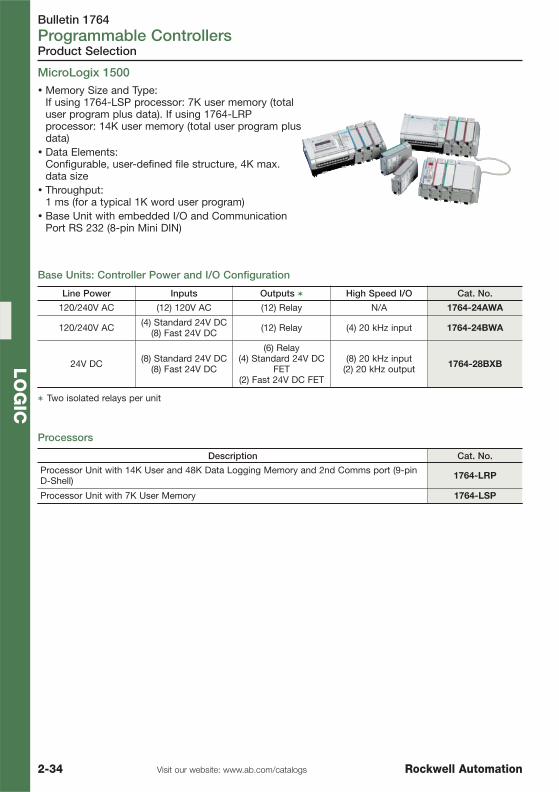
Bulletin 1764Programmable Controllers
2-34 Visit our website: www.ab.com/catalogs Rockwell Automation
LO
GIC
Product Selection
Description Cat. No.
Processor Unit with 14K User and 48K Data Logging Memory and 2nd Comms port (9-pinD-Shell) 1764-LRP
Processor Unit with 7K User Memory 1764-LSP
Line Power Inputs Outputs � High Speed I/O Cat. No.
120/240V AC (12) 120V AC (12) Relay N/A 1764-24AWA
120/240V AC (4) Standard 24V DC(8) Fast 24V DC (12) Relay (4) 20 kHz input 1764-24BWA
24V DC (8) Standard 24V DC(8) Fast 24V DC
(6) Relay(4) Standard 24V DC
FET(2) Fast 24V DC FET
(8) 20 kHz input(2) 20 kHz output 1764-28BXB
� Two isolated relays per unit
Processors
Base Units: Controller Power and I/O Configuration
MicroLogix 1500� Memory Size and Type:
If using 1764-LSP processor: 7K user memory (totaluser program plus data). If using 1764-LRPprocessor: 14K user memory (total user program plusdata)
� Data Elements:Configurable, user-defined file structure, 4K max.data size
� Throughput:1 ms (for a typical 1K word user program)
� Base Unit with embedded I/O and CommunicationPort RS 232 (8-pin Mini DIN)

Bulletin 1764Programmable Controllers
2-35Visit our website: www.ab.com/catalogsRockwell Automation
LO
GIC
See publication 1761-SG001… for complete product information.
Product Selection
� User programs and data to be stored as backup� Transport programs for use with other controllers� Safety/security for press control and other critical applications� Auto recovery, through a power cycle, after a controller fault� Comparison of programs� Data file and memory module write protection
Data Access Tool
Memory and Real-Time Clock Modules
Description Cat. No.
� Direct access to 48 bit elements� Direct access to 48 integer elements� Two function keys� Display of controller faults� Removal/Insertion under Power
1764-DAT
Description Memory size Cat. No.
Real-Time Clock not applicable 1764-RTC
Memory Module 8K 1764-MM1
Memory Module and Real-Time Clock 8K 1764-MM1RTC
Memory Module 16K � 1764-MM2
Memory Module and Real-Time Clock 16K � 1764-MM2RTC
Memory Module 32K � 1764-MM3
Memory Module and Real-Time Clock 32K � 1764-MM3RTC
� For the 1764-LRP processor to support larger program and data requirements.
Programming software, network interface devices and cables see page 2-36

Bulletin 1769Programmable Controllers
2-36 Visit our website: www.ab.com/catalogs Rockwell Automation
LO
GIC
Description Length Cable Type Cat. No.
Cable to connect port 1 to the 9-Pin DTEport of a personal computer 3 m 9-pin D Shell to
9-pin D Shell 1747-CP3
Cable to connect the MicroLogix 1500 baseport to an IBM compatible PC 2 m 9-pin D Shell to
8-pin Mini DIN 1761-CBL-PM02
Note: Only cables of series C or later can be used with MicroLogix 1100
Description Cat. No.
RSLogix 500 Starter Edition Progr. Software for MicroLogix controller families. (CD-ROM) 9324-RL0100ENE
RSLogix 500 Standard Edition Programming Software for SLC 500 and MicroLogixcontroller families. (CD-ROM) 9324-RL0300ENE
RSLogix 500 Professional Edition. CD-ROM also includes RSLogix Emulate 500,RSNetworx for DeviceNet and RSNetworx for ControlNet. 9324-RL0700NXENE
RSLogix Micro Starter 9324-RLM0100ENE
RSLogix Micro Developer 9324-RLM0800ENE
Accessories
The RSLogix 500 ladder logic programming package helps you maximize performance, save projectdevelopment time, and improve productivity. This product has been developed to operate onWindows 98 and above operating system. RSLogix 500 can be used for programming both theSLC 500 and MicroLogix controller families.
Programming Cable for MicroLogix 1500 with 1764-LRP Processor, Channel 1 (9-pin RS-232)
Programming Software
Description Length Cable Type Cat. No.
Cable to connect MicroLogix controller to anIBM compatible PC 2 m 8-pin Mini DIN to
9-pin D Shell 1761-CBL-PM02
Accessories for MicroLogix 1000, 1100, 1200, 1400 and 1500
Programming Cable for MicroLogix 1000, 1100, 1200, 1400 and 1500 Channel 0 (8-pin Mini DIN)
Wiring Systems for MicroLogix 1200 and 1500, see page 4-11 in chapter Connectivity.

Bulletin 1769Programmable Controllers
2-37Visit our website: www.ab.com/catalogsRockwell Automation
LO
GIC
Description Cat. No.
AIC+ Advanced Interface Converter: The AIC+ provides an interface to DH-485 networks from an RS-232 port. It can be usedwith all MicroLogix controllers, SLC 5/03 and higher, and a number of PanelView terminals.
1761-NET-AIC
DNI DeviceNet Interface: Peer-to-peer messaging between MicroLogix controllers and other devices using the DF1Full-Duplex protocol (real time communications – no polling required)
1761-NET-DNI
ENI Ethernet Interface:The ENI provides EtherNet/IP connectivity for all MicroLogix controllers and other DF1 Full-Duplex devices:The ENIW provides also a basic level of Web Server functionality including:� Ability to display dynamically updated data values� Ability to label data values� Ability to modify data values (password protected)
1761-NET-ENI
1761-NET-ENIW
Note: External power is required for the network interface. The MicroLogix 1100 RS232/485 port does not provideany power for connected devices.
1761-NET-AIC+
DH-485 ———
RS232 ———9-PinD-Shell
—— RS-2328-Pin Mini DIN
1761-NET-DNI
DeviceNet ——
—— RS-2328-Pin Mini DIN
1761-NET-ENI
EtherNet ———— RS-232
8-Pin Mini DIN
Accessories
Network Cable
Network Interface Devices
Description Connectors Length Cat. No.
Used to connect MicroLogix controller toPort 2 of 1761-NET-AIC+ or 1761-NET-DNIor 1761-HHP or PanelView
8-pin Mini DIN to8-pin Mini DIN
0.5 m 1761-CBL-AM00
2 m 1761-CBL-HM02
5 m 2711-CBL-HM05
10 m 2711-CBL-HM10
Used to connect MicroLogix 1500 Processor(LRP) or Port 1 of 1761-NET-AIC+ to 9-pinDTE of Personal Computer
9-pin D Shell to9-pin D Shell
0.5 m 1761-CBL-AC00
3 m 1747-CP3
Used to connect MicroLogix controller toPort 1 of 1761-NET-AIC+ or MicroLogixcontroller to PC or PanelView's toMicroLogix controller
8-pin Mini DIN to9-pin D Shell
0.5 m 1761-CBL-AP00
2 m 1761-CBL-PM02
5 m 2711-CBL-PM05
10 m 2711-CBL-PM10
Note: Do not connect a MicroLogix 1100 controller to another MicroLogix family controller such as MicroLogix1000, 1200 or 1500 using a 1761-CBL-AM00 (8-pin Mini DIN to 8-pin Mini DIN) cable or equivalent.This type connection will cause damage to the RS-232/485 communication port (Channel 0) of the MicroLogix1100 and/or the controller itself.
Accessories for MicroLogix 1000, 1100, 1200, 1400 and 1500, continued
Use the communication cables listed below with MicroLogix 1000, 1100, 1200, 1400 and 1500controllers. Cables come in several lengths and connector styles to provide connectivity betweenMicroLogix controllers and other devices.

Bulletin 1492-RCD, 1492-SP, 1492-FB, 1489, 140FCircuit Protection
2-38 Visit our website: www.ab.com/catalogs Rockwell Automation
LO
GIC
Device Selection
Product Line Overview
Bulletin 1492-RCD 1492-SP
Type Residual Current Device Miniature Circuit Breaker
Features
� True IP2X finger-safe design (front)� For applications in which AC and
pulsating DC fault currents are likely toappear, nonselective and non-delayed
� Designed to prevent unwanted trippingcaused by switching electronic circuitdevices
� Auxiliary and Signal contacts may beadded
� True IP2X finger-safe design (front)� Energy Limiting Design protects
downstream components better thanconventional breakers during shortcircuits
� Field mountable options for selectiveapplications
� AC and DC voltage ratings in oneconvenient device
� Superior shock and vibration resistancecapabilities
� Mounts on hut (DIN) rail
Number of Poles 2 pole (1 + N)4 pole (3 + N)
1, 2, 3 pole1 pole + neutral, 3 pole + neutral
Rated voltage 230V AC (1+N), 400V AC (3+N) 230/400V AC, 240/415V AC
Tripping characteristic reference temperature — 30 °C
Rated tripping current 30, 100, 300, 500 mA —
Sensitivity AC and pulsating DC —
Rated short circuit capability
10 kA with 63 A gG/gL back-up fuse for up to 63 A
10 kA with 80 A gG/gL back-up fuse for 80 A
10 kA
Max. back-up fuse for short circuit protection
63 A gG/gL for up to 63 A80 A gG/gL for 80 A 100 A gG/gL
Maximum back-up fuse for overload protection
25 A gG/gL (25 A and 40 A devices)40 A gG/gL (63 A devices)50 A gG/gL (80 A devices)
—
Degree of protection IP20 IP20
Mechanical life ≥10000 changeovers ≥6000 changeovers
Mounting 35 mm hut (DIN) rail 35 mm hut (DIN) rail
Operating temperature -5°C…+40°C-5°C…+40°C
(reduction factors are required for higher temperatures )
Wire size 1.5…35 mm2 1…25 mm2
Terminal torque 2.4 N.m ≤40 A, 3.0 N.m ≥63 A 2.4 N.m
Standards andApprovals
IEC/EN 61008VDE, CE
IEC/EN 60889CE, VDE, UL 1077, CSA 22.2 No. 235
Product Selection See page 2-41 See page 2-43

Bulletin 1492-RCD, 1492-SP, 1492-FB, 1489, 140FCircuit Protection
2-39Visit our website: www.ab.com/catalogsRockwell Automation
LO
GIC
Product Line Overview
Device Selection
Bulletin 1489 1492-FB
Type480Y/277V AC 240V AC For Class
CC Fuse For Class J Fuse For MidgetFuse
0.5…25 A 0.5…40 A 30 A 30 A 60 A 30 A
Features
� True IP2X finger-safe design(front)
� 10,000 A interrupt� A postively trip-free
mechanism (breaker operationcannot be defeated by holdingthe handle in the ON position)
� Superior shock and vibrationresistance capabilties
� Mounts on DIN Rail� IEC 60947-2
- 0.5...40 A @ 240, 415V AC- 15,000 A interrupting
� Field-mountable options� Optional terminal for ring lugs
� EN/IEC 60529 Front Finger Protection — Deadfront construction
� Handle isolates the fuse from line power when itis opened for fuse insertion or removal
� Compact size requireing less panel space thanopen style fuse folders
� Optional blown fuse indicators - allow for easytroubleshooting of electrical circuits
� Type M holder - accepts 0…30 A midget fuses (11/2" x 13/32")
� Type C holder - accepts 0…30 A Class CC fuses)� Type J 30 & 60 A holders - accepts Class J fuses� Silver-plated fuse clips� Mounts on DIN rail, marker-ready and increased
heat dissipation
CertificationsUL 489 Listed (CSA C22.2 No.5.1), UL File Number E197878
VDE (SEC 60 947-2)CE, ULus, CSA CE, URus, CSA
Maximum Voltage Rating 480Y/277V AC 600V AC/DC
Shock 25 G Half Sine Wave for 11 ms(Three Axes) 25 G Half Sine Wave for 11 ms (Three Axes)
Tripping CharacteristicReference Temperature
40°C (UL/CSA)30°C (IEC) NA
Tripping Characteristic C Curve: 5…10D Curve: 10…20 NA
Vibration
100...500 Hz for 1 hourAmplitude — 10...57 Hz; 0.030inches peak to peak; 57...500
Hz; 5 G peak
5 G peak or 0.030 "peak-to-peak" displacement for2 hours in each perpendicular direction. Vibration
sweep 10 to 2000 to 10 Hz (15 minutes long)
Operating Temperature -13...140°F (-25...+55°C),non-condensing -4...130°F (–20…+55°C)
Housing Material Nylon Nylon
WorkingVoltage —
110…600VAC/DC or12…72VAC/DC
110…600V AC/DC
110…600VAC/DC or12…72VAC/DC
WithIndicator
LeakageCurrent LED — 2.0 mA
Wire Size 0.8...13 mm2/#18...6 AWG Cu #16…4 AWGCu
#14…1AWG Cu
#10…1AWG Cu
#16…4 AWGCu
Interrupt Rating 10 kA @ 240V AC and 480Y/277V AC (UL/CSA) 200 kA 50 kA
Product Selection See page 2-49 See page 2-51

Bulletin 1492-RCD, 1492-SP, 1492-FB, 1489, 140FCircuit Protection
2-40 Visit our website: www.ab.com/catalogs Rockwell Automation
LO
GIC
Product Line Overview
Device Selection
Bulletin 140F
Type MCS Fuse Holders
Features
� Available for UL Class CC or Midget Fuses, with or without blown fuse indication� Lockable in the open position� Compatible with 140M accessories� Compact busbar and connectors of contactors 100C and 100M� 1 NO/ 1 NC Auxiliary Contact, early break NC� Provides capability for dropping out contactor before breaking current on fuse� Late make NO provides positive indication that power circuit is open
Product Selection See page 2-52

Bulletin 1492-RCDResidual Current Devices
2-41Visit our website: www.ab.com/catalogsRockwell Automation
LO
GIC
Residual Current Devices Bulletin 1492-RCD
Standard Versions
1492-RCD2 1492-RCD4
The Bulletin 1492-RCD line includes ResidualCurrent Devices for earth leakage detection to IECstandards. These devices are used in associationwith miniature circuit breakers (1492-SP).
Earth Leakage Detectors for IEC Applications
Product Overview
� True IP2X finger-safe design (front)� Undelayed tripping time� Line-voltage independent tripping (suitable for residual current & additional protection)� Rated tripping current: 30, 100, 300, 500 mA� For applications in which AC and pulsating DC fault currents are likely to appear, nonselective and
non-delayed� Designed to prevent unwanted tripping caused by switching electronic circuit devices� Mounts on DIN Rail� Busbar position on top or bottom� Conditionally surge current proof 250 A� Rated Short-Circuit strength: 10 kA with 63 A gG/gL back-up fuse, 10 kA with 80 A gG/
gL back-up fuse for 80 A device
OperatingVoltage, Nominal
Rated TrippingCurrent
RatedOperational
Current 2 poles (1 pole + neutral) 4 poles (3 poles + neutral)
[V] [mA] [A] Cat. No. Cat. No.
230/400V 50 Hz
30
16 1492-RCD2A16 —
25 1492-RCD2A25 1492-RCD4A25
40 1492-RCD2A40 1492-RCD4A40
63 — 1492-RCD4A63
80 — 1492-RCD4A80
100
25 1492-RCD2B25 1492-RCD4B25
40 1492-RCD2B40 1492-RCD4B40
63 — 1492-RCD4B63
300
16 — 1492-RCD4C16
25 1492-RCD2C25 1492-RCD4C25
40 1492-RCD2C40 1492-RCD4C40
63 — 1492-RCD4C63
80 — 1492-RCD4C80

Bulletin 1492-RCDResidual Current Devices
2-42 Visit our website: www.ab.com/catalogs Rockwell Automation
LO
GIC
Accessories 1492-RCD
Versions for Use with Variable Frequency Drives
Product Selection / Accessories
Description Diagram Cat. No.
Dual auxiliary contact moduleSwitches when protective device is operated manuallyor tripped electrically2 N.O. – 2 N.C. 2 Form C Contact
22 24
21
12 14
11
1492-ASPHH3
Auxiliary/Signal alarm contact module1 Auxiliary Contact switches when protective device isoperated manually or tripped electrically1 N.O. – 1 N.C. Form C Contact1 Signal Contact switches when protective device istripped electrically1 N.O. – 1 N.C. Form C Contact
12 14
11
96 98
95
1492-ASPHS3
Operating Voltage,Nominal Rated Tripping Current Rated Operational Current 4 poles (3 poles + neutral)
[V] [mA] [A] Cat. No.
230/400V 50 Hz
10040 1492-RCD4B40D
63 1492-RCD4B63D
30040 1492-RCD4C40D
63 1492-RCD4C63D
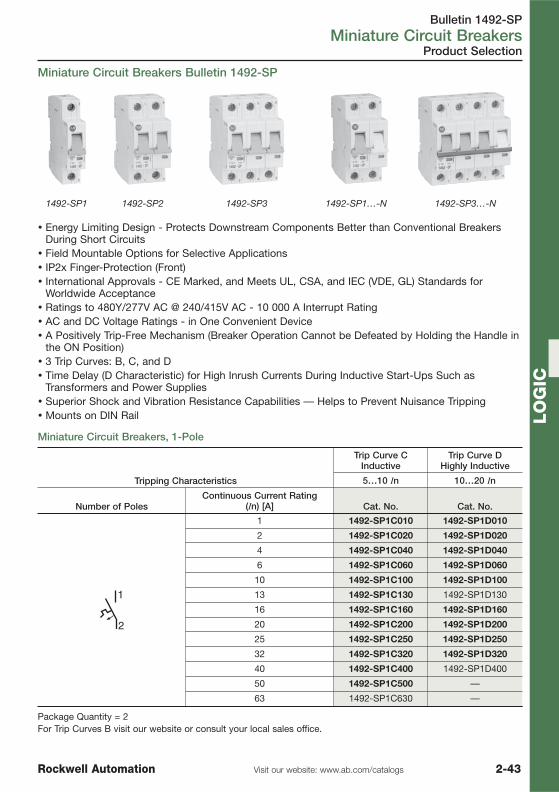
Bulletin 1492-SPMiniature Circuit Breakers
2-43Visit our website: www.ab.com/catalogsRockwell Automation
LO
GIC
Product Selection
� Energy Limiting Design - Protects Downstream Components Better than Conventional BreakersDuring Short Circuits
� Field Mountable Options for Selective Applications� IP2x Finger-Protection (Front)� International Approvals - CE Marked, and Meets UL, CSA, and IEC (VDE, GL) Standards for
Worldwide Acceptance� Ratings to 480Y/277V AC @ 240/415V AC - 10 000 A Interrupt Rating� AC and DC Voltage Ratings - in One Convenient Device� A Positively Trip-Free Mechanism (Breaker Operation Cannot be Defeated by Holding the Handle in
the ON Position)� 3 Trip Curves: B, C, and D� Time Delay (D Characteristic) for High Inrush Currents During Inductive Start-Ups Such as
Transformers and Power Supplies� Superior Shock and Vibration Resistance Capabilities — Helps to Prevent Nuisance Tripping� Mounts on DIN Rail
1492-SP1 1492-SP2 1492-SP3 1492-SP1…-N 1492-SP3…-N
Tripping Characteristics
Trip Curve CInductive
Trip Curve DHighly Inductive
5…10 In 10…20 In
Number of PolesContinuous Current Rating
(In) [A] Cat. No. Cat. No.
1 1492-SP1C010 1492-SP1D010
2 1492-SP1C020 1492-SP1D020
4 1492-SP1C040 1492-SP1D040
6 1492-SP1C060 1492-SP1D060
10 1492-SP1C100 1492-SP1D100
13 1492-SP1C130 1492-SP1D130
16 1492-SP1C160 1492-SP1D160
20 1492-SP1C200 1492-SP1D200
25 1492-SP1C250 1492-SP1D250
32 1492-SP1C320 1492-SP1D320
40 1492-SP1C400 1492-SP1D400
50 1492-SP1C500 —
63 1492-SP1C630 —
Package Quantity = 2For Trip Curves B visit our website or consult your local sales office.
Miniature Circuit Breakers Bulletin 1492-SP
Miniature Circuit Breakers, 1-Pole

Bulletin 1492-SPMiniature Circuit Breakers
2-44 Visit our website: www.ab.com/catalogs Rockwell Automation
LO
GIC
Product Selection
Tripping Characteristics
Trip Curve CInductive
Trip Curve DHighly Inductive
5…10 In 10…20 In
Number of PolesContinuous Current Rating
(In) [A] Cat. No. Cat. No.
1 1492-SP2C010 1492-SP2D010
2 1492-SP2C020 1492-SP2D020
4 1492-SP2C040 1492-SP2D040
6 1492-SP2C060 1492-SP2D060
10 1492-SP2C100 1492-SP2D100
13 1492-SP2C130 1492-SP2D130
16 1492-SP2C160 1492-SP2D160
20 1492-SP2C200 1492-SP2D200
25 1492-SP2C250 1492-SP2D250
32 1492-SP2C320 1492-SP2D320
40 1492-SP2C400 1492-SP2D400
50 1492-SP2C500 —
63 1492-SP2C630 —
For Trip Curves B visit our website or consult your local sales office.
Miniature Circuit Breakers, 2-Poles
Miniature Circuit Breakers, 3-Poles
Tripping Characteristics
Trip Curve CInductive
Trip Curve DHighly Inductive
5…10 In 10…20 In
Number of PolesContinuous Current Rating
(In) [A] Cat. No. Cat. No.
1 1492-SP3C010 1492-SP3D010
2 1492-SP3C020 1492-SP3D020
4 1492-SP3C040 1492-SP3D040
6 1492-SP3C060 1492-SP3D060
10 1492-SP3C100 1492-SP3D100
13 1492-SP3C130 1492-SP3D130
16 1492-SP3C160 1492-SP3D160
20 1492-SP3C200 1492-SP3D200
25 1492-SP3C250 1492-SP3D250
32 1492-SP3C320 1492-SP3D320
40 1492-SP3C400 1492-SP3D400
50 1492-SP3C500 —
63 1492-SP3C630 —
For Trip Curves B visit our website or consult your local sales office.

Bulletin 1492-SPMiniature Circuit Breakers
2-45Visit our website: www.ab.com/catalogsRockwell Automation
LO
GIC
Product Selection
Tripping Characteristics
Trip Curve CInductive
Trip Curve DHighly Inductive
5…10 In 10…20 In
Number of PolesContinuous Current Rating
(In) [A] Cat. No. Cat. No.
2
1
N
N
1 1492-SP1C010-N 1492-SP1D010-N
2 1492-SP1C020-N 1492-SP1D020-N
4 1492-SP1C040-N 1492-SP1D040-N
6 1492-SP1C060-N 1492-SP1D060-N
10 1492-SP1C100-N 1492-SP1D100-N
13 1492-SP1C130-N 1492-SP1D130-N
16 1492-SP1C160-N 1492-SP1D160-N
20 1492-SP1C200-N 1492-SP1D200-N
25 1492-SP1C250-N 1492-SP1D250-N
32 1492-SP1C320-N 1492-SP1D320-N
40 1492-SP1C400-N 1492-SP1D400-N
50 1492-SP1C500-N —
63 1492-SP1C630-N —
For Trip Curves B visit our website or consult your local sales office.
Tripping Characteristics
Trip Curve CInductive
Trip Curve DHighly Inductive
5…10 In 10…20 In
Number of PolesContinuous Current Rating
(In) [A] Cat. No. Cat. No.
2
1
4
3
6
5
N
N
1 1492-SP3C010-N 1492-SP3D010-N
2 1492-SP3C020-N 1492-SP3D020-N
4 1492-SP3C040-N 1492-SP3D040-N
6 1492-SP3C060-N 1492-SP3D060-N
10 1492-SP3C100-N 1492-SP3D100-N
13 1492-SP3C130-N 1492-SP3D130-N
16 1492-SP3C160-N 1492-SP3D160-N
20 1492-SP3C200-N 1492-SP3D200-N
25 1492-SP3C250-N 1492-SP3D250-N
32 1492-SP3C320-N 1492-SP3D320-N
40 1492-SP3C400-N 1492-SP3D400-N
50 1492-SP3C500-N —
63 1492-SP3C630-N —
For Trip Curves B visit our website or consult your local sales office.
Miniature Circuit Breakers, 1-Pole + Neutral Module
Miniature Circuit Breakers, 3-Poles + Neutral Module

Bulletin 1492-SPMiniature Circuit Breakers
2-46 Visit our website: www.ab.com/catalogs Rockwell Automation
LO
GIC
Accessories
Description Diagram PQ Cat. No.
Auxiliary contact moduleSwitches when protective device is operatedmanually or tripped electrically1 N.O. – 1 N.C. Form C Contact
14
11
12
1 1492-ASPH3
Dual auxiliary contact moduleSwitches when protective device is operatedmanually or tripped electrically2 N.O. – 2 N.C. 2 Form C Contact
22 24
21
12 14
11
1 1492-ASPHH3
Auxiliary/Signal alarm contact module1 Auxiliary Contact switches when protectivedevice is operated manually or tripped electrically1 N.O. – 1 N.C. Form C Contact1 Signal Contact switches when protectivedevice is tripped electrically1 N.O. – 1 N.C. Form C Contact
12 14
11
96 98
95
1 1492-ASPHS3
Undervoltage release moduleUse the undervoltage release module to trip theadjacent breaker poles when the applied voltageis less than the nominal voltage.Undervoltage trip is often used when loss ofpower and eventual restoration of power createsan unsafe or unknown set of condition.
D1
<
D2
U
50…115V AC 1 1492-ASPU115
110…240VAC 1 1492-ASPU230
Shunt trip moduleUse the shunt trip module to trip the adjacentbreaker poles from a remote location.The module is actuated by applying a voltage(pickup voltage) to the trip terminals.Shunt trip modules are often used in emergencyshutdown circuits where multiple power circuitsmust be switched off from a single location.
110…415VAC
(110…230VDC)
1 1492-ASPA1
12…110V AC(12…60V DC) 1 1492-ASPA2
Mounting RailsDIN (#3) Symmetrical Rail35 x 7.5 x 1 m
10 199-DR1
DIN hi-rise symmetrical rail1 m, 35 mm x 7.5 mm, 57.4 mm (2.26 in.) highCopper-free aluminum
2 1492-DR6
DIN angled hi-rise symmetrical rail1 m, 35 mm x 7.5 mm, 71.0 mm (2.80 in.) highZinc-plated, chromated steel
2 1492-DR7
End Anchor 10 1492-EAH35
Lockout Attachment 10 1492-ASPLOA
PQ = Package Quantity

Bulletin 1492-SPMiniature Circuit Breakers
2-47Visit our website: www.ab.com/catalogsRockwell Automation
LO
GIC
Description No. of 1492-SPRated Operational
Current (Ie) [A] PQ Cat. No.
Incoming Terminals for fork style commoning links, IP20 protection(Not for use in North American installations)
For max 25 mm2 wire 1 1492-ASPCLT25
For max 35 mm2 wire 1 1492-ASPCLT35
Fork Style Commoning Linksfor 1492-SP without Auxiliary Contact Module (may not be cut)
1 pole 2 63 20 1492-ASPCL102
1 pole 6 63 20 1492-ASPCL106
1 pole 12 63 20 1492-ASPCL112
2 poles (1p + N) 2 63 10 1492-ASPCL204
2 poles (1p + N) 3 63 10 1492-ASPCL206
2 poles (1p + N) 6 63 10 1492-ASPCL212
3 poles 2 63 10 1492-ASPCL306
3 poles 4 63 10 1492-ASPCL312
4 poles 2 63 1 1492-ASPCL408
4 poles 3 63 1 1492-ASPCL412
Fork Style Commoning Linksfor 1492-SP with an Auxiliary Contact Module or Auxiliary/Signal Alarm Contact Module
1 pole 2 63 20 1492-ASPCL1A02
1 pole 6 63 20 1492-ASPCL1A06
1 pole 9 63 20 1492-ASPCL1A09
2 poles (1p + N) 2 63 10 1492-ASPCL2A04
2 poles (1p + N) 3 63 10 1492-ASPCL2A06
2 poles (1p + N) 5 63 10 1492-ASPCL2A10
3 poles 2 63 10 1492-ASPCL3A06
3 poles 4 63 10 1492-ASPCL3A12
PQ = Package Quantity
Accessories

Bulletin 1492-SPMiniature Circuit Breakers
2-48 Visit our website: www.ab.com/catalogs Rockwell Automation
LO
GIC
Description No. of 1492-SPRated Operational
Current (Ie) [A] PQ Cat. No.
Fork Style Commoning Linksfor multiple single pole 1492-SP, each with 1 Auxiliary Contact or 1 Auxiliary/Signal Alarm Contact Module
2x3 (1p) 63 10 1492-ASPCL3AP06
2x3 (1p)+2 (1p) 63 10 1492-ASPCL3AP08
3x3 (1p) 63 10 1492-ASPCL3AP09
Protective coverfor unused fork termination 5 1492-ASPCLPS
Fork Style Commoning Links(may be cut to length, not for use with accessories)
1 pole 1 m (56 devices/m) 63 1 1492-ASPCL1
3 poles 1 m (19 devices/m) 63 1 1492-ASPCL3
End Cap (for 2 and 3 poles) 10 1492-ASPEC1
Pin Style Commoning Links(may be cut to length, not for use with accessories)
1 pole 1 m (57 devices/m) 80 1 1492-A1B8
2 poles (1P + N) 1 m (29 devices/m) 80 1 1492-A2B8
3 poles 1 m (19 devices/m) 80 1 1492-A3B8
End Caps for use with Two and Three Phase Bus Bar 10 1492-AME
PQ = Package Quantity
Accessories

Bulletin 1489Miniature Circuit Breakers
2-49Visit our website: www.ab.com/catalogsRockwell Automation
LO
GIC
Miniature Circuit Breakers, Trip Curve "C"
Miniature Circuit Breakers Bulletin 1489
� IP2x Finger-Protection (Front)� North America certifications: UL 489, CSA 22.2 No. 5.1� International standards: CE Marked, and IEC (VDE) standards for
worldwide acceptance� Ratings: UL/CSA — max. 480Y/277V AC – 10,000 A interrupt rating;
IEC — max. 240/415V AC – 15,000 A interrupt rating� Trip curves: C and D� Time delay (D Characteristic) for high inrush currents during inductive
start-ups Such as motors, transformers and power supplies� Mounts on Standard 35 mm DIN Rail (A-B p/n 199-DR1)
No. of Poles Rated Current [A] UL/CSA Max. Volt. Cat. No.
1-Pole
2
480Y/277V AC, 48V DC
1489-A1C020
4 1489-A1C040
6 1489-A1C060
10 1489-A1C100
16 � 1489-A1C160
2-Pole
2 480Y/277V AC, 96V DC 1489-A2C020
4 480Y/277V AC, 96V DC 1489-A2C040
6 480Y/277V AC, 96V DC 1489-A2C060
10 480Y/277V AC, 96V DC 1489-A2C100
16 � 480Y/277V AC, 96V DC 1489-A2C160
3-Pole
2 480Y/277V AC 1489-A3C020
4 480Y/277V AC 1489-A3C040
6 480Y/277V AC 1489-A3C060
10 480Y/277V AC 1489-A3C100
16 � 480Y/277V AC 1489-A3C160
� Common IEC current rating.
Product Selection

Bulletin 1489Miniature Circuit Breakers
2-50 Visit our website: www.ab.com/catalogs Rockwell Automation
LO
GIC
Miniature Circuit Breaker Accessories
See Publication 1489-SG001… for complete product information.
Accessories
Description
CSA/ULCertifi-cations
IEC 60947-2Compliance CE
EN/IEC Max.Volt.
UL/CSA Max.Volt. Connection Cat. No.
LockoutAttachment Yes Yes — — — — 1489-AALOA
Auxiliary Contact,2 sets, each are
Form C, 1 N.O. &1 N.C.
Yes Yes —
3 A, 250V AC(AC13)
0.5 A, 110VDC
2 A, 240V AC0.5 A, 110V
DCCable � 1489-AAHH3
Auxiliary/SignalContact, eachare form C, 1N.O. & 1 N.C
Yes Yes —
3 A, 250V AC(AC13)
0.5 A, 110VDC
2 A, 240V AC0.5 A, 110V
DCCable � 1489-AAHS3
Auxiliary Contact,Feed Through, 1
N.O. & 1 N.C. Yes Yes —
3 A, 250V AC(AC13)
0.5 A, 110VDC
2 A, 230V AC0.5 A, 110V
DCCable � 1489-ABH12
Shunt TripModule Yes Yes —
110...415V AC110…230V
DC
110...415V AC110…230V
DCCable 1489-AASTA1
Shunt TripModule Yes Yes — 12...110V AC
12…60V DC12...110V AC12…60V DC Cable 1489-AASTA2
� Use of auxiliary or signal contact limits the circuit breaker to a maximum voltage of 240V AC for UL/CSAapplications.
�Use of this auxiliary contact allows application of the circuit breaker to full rating of 480Y/ 277V AC for UL/CSAapplications.
Bulletin 1489 Bus Bar
Description No. of Poles No. of PhasesNumber of Circuit
Breakers PQ Cat. No.
Bus Bar �
6
1
6
10
1489-AACL106
12 12 1489-AACL112
18 18 1489-AACL118
6
2
3 1489-AACL206
12 6 1489-AACL212
18 9 1489-AACL218
6
3
2 1489-AACL306
12 4 1489-AACL312
18 6 1489-AACL318
� UL 489 recognized (E300325), CE
Bulletin 1489 Bus Bar Accessories
Description No. of Poles Wire Range PQ Cat. No.
Terminal Lug 1-pole for circuit breakertermination
#14 … #2 AWG2.5 … 35 mm2 10 1489-AACLT35
Protective Cover for unusedtermination 3-pole set (may be separated) — 10 1489-AACLPS
PQ = Package Quantity

Bulletin 1492-FBDIN Rail Mounting Fuse Holders
2-51Visit our website: www.ab.com/catalogsRockwell Automation
LO
GIC
Description PQ
For Class J Fuse
30 A 60 A
Cat. No. Cat. No.
1-Pole1-Pole Fuse Block 6 1492-FB1J30 1492-FB1J60
1-Pole Fuse Block with Indication 6 1492-FB1J30-L 1492-FB1J60-L
2-Poles2-Pole Fuse Block 3 1492-FB2J30 1492-FB2J60
2-Pole Fuse Block with Indication 3 1492-FB2J30-L 1492-FB2J60-L
3-Poles3-Pole Fuse Block 2 1492-FB3J30 1492-FB3J60
3-Pole Fuse Block with Indication 2 1492-FB3J30-L 1492-FB3J60-L
PQ = Package Quantity
DIN Rail Mounting Fuse Holders for Class J Fuse
DIN Rail Mounting Fuse Holders 1492-FB
Product Selection
� EN/IEC 60529 Finger Protection — Dead Front Construction� The Patented Handle Design Isolates the Fuse from Power When Handle
is Opened for Fuse Insertion or Removal� Optional Blown Fuse LED Indicator — Allow for Easy Troubleshooting of
Electrical Circuits� Easy Insertion/Removal of Fuses, No Special Tools Required� Mounts on Standard 35 mm DIN Rail (A-B p/n 199-DR1)
DIN Rail Mounting Fuse Holders for Class CC / Midget Fuse
Description PQ
For Class CC Fuse For Midget Fuse
30 A � 30 A
Cat. No. Cat. No.
1-Pole
Fuse Block 6 1492-FB1C30 1492-FB1M30
1-Pole Fuse Block with Indication 6 1492-FB1C30-L 1492-FB1M30-L
1-Pole Fuse Block with Indication, 12…72V 6 1492-FB1C30-D1 1492-FB1M30-D1
2-Poles2-Pole Fuse Block 3 1492-FB2C30 1492-FB2M30
2-Pole Fuse Block with Indication 3 1492-FB2C30-L 1492-FB2M30-L
3-Poles3-Pole Fuse Block 2 1492-FB3C30 1492-FB3M30
3-Pole Fuse Block with Indication 2 1492-FB3C30-L 1492-FB3M30-L
� All major fuse brands and current ranges have been evaluated for this fuse holder. Due to the heat they generate,the following fuses must be derated:
Ferraz Shamut ATQR 1.25 I = 0.42 A max.Ferraz Shamut ATQR 1.40 I = 0.47 A max.PQ = Package Quantity

Bulletin 140FMCS Fuse Holders
2-52 Visit our website: www.ab.com/catalogs Rockwell Automation
LO
GIC
� Available for UL Class CC or Midget Fuses and IEC 10 x 38 mm fuses,with or without blown fuse indication
� Lockable in the open position� Compatible with 140M accessories� Compact busbar and connectors of contactors 100C and 100M� 1 NO/ 1 NC Auxiliary Contact, early break NC� Provides capability for dropping out contactor before breaking current
on fuse� Late make NO provides positive indication that power circuit is open
MCS Fuse Holders 140F
Description
Approvals
Cat. No.IEC CE Mark UL CSA
Fuse Holder, UL Class CC — 30 A max. Yes Yes Yes Yes 140F-D3C-C30
Fuse Holder with Blown Fuse Indication, ULClass CC — 30 A max. Yes Yes Yes Yes 140F-D3C-C30L
Fuse Holder, UL Midget — 30 A max. Yes Yes Yes Yes 140F-D3M-C30
Fuse Holder with Blown Fuse Indication, ULMidget — 30 A max. Yes Yes Yes Yes 140F-D3M-C30L
Fuse Holder, IEC 10 x 38 mm — 32 A max. Yes Yes No No 140F-D3F-C30
Fuse Holder with Blown Fuse Indication, IEC10 x 38 mm — 32 A max. Yes Yes No No 140F-D3F-C30L
Auxiliary Contact for Fuse Holder (1 N.O.Late Make + 1 N.C. Early Break) Yes Yes Yes Yes 140F-C-AFA11
For additional accessories refer to contactors 100M/100-C and circuit breakers 140M.
Product Selection
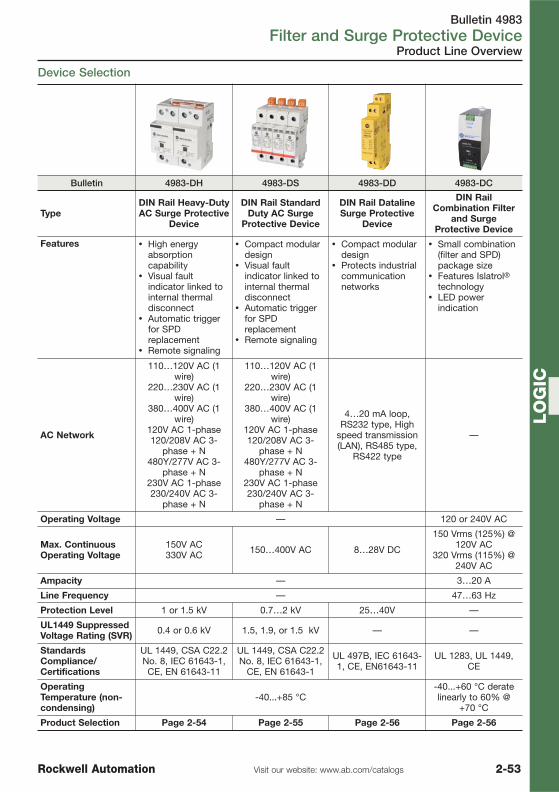
Bulletin 4983Filter and Surge Protective Device
2-53Visit our website: www.ab.com/catalogsRockwell Automation
LO
GIC
Product Line Overview
Device Selection
Bulletin 4983-DH 4983-DS 4983-DD 4983-DC
TypeDIN Rail Heavy-DutyAC Surge Protective
Device
DIN Rail StandardDuty AC Surge
Protective Device
DIN Rail DatalineSurge Protective
Device
DIN RailCombination Filter
and SurgeProtective Device
Features � High energyabsorptioncapability
� Visual faultindicator linked tointernal thermaldisconnect
� Automatic triggerfor SPDreplacement
� Remote signaling
� Compact modulardesign
� Visual faultindicator linked tointernal thermaldisconnect
� Automatic triggerfor SPDreplacement
� Remote signaling
� Compact modulardesign
� Protects industrialcommunicationnetworks
� Small combination(filter and SPD)package size
� Features Islatrol®technology
� LED powerindication
AC Network
110…120V AC (1wire)
220…230V AC (1wire)
380…400V AC (1wire)
120V AC 1-phase120/208V AC 3-
phase + N480Y/277V AC 3-
phase + N230V AC 1-phase230/240V AC 3-
phase + N
110…120V AC (1wire)
220…230V AC (1wire)
380…400V AC (1wire)
120V AC 1-phase120/208V AC 3-
phase + N480Y/277V AC 3-
phase + N230V AC 1-phase230/240V AC 3-
phase + N
4…20 mA loop,RS232 type, High
speed transmission(LAN), RS485 type,
RS422 type
—
Operating Voltage — 120 or 240V AC
Max. ContinuousOperating Voltage
150V AC330V AC 150…400V AC 8…28V DC
150 Vrms (125%) @120V AC
320 Vrms (115%) @240V AC
Ampacity — 3…20 A
Line Frequency — 47…63 Hz
Protection Level 1 or 1.5 kV 0.7…2 kV 25…40V —
UL1449 SuppressedVoltage Rating (SVR) 0.4 or 0.6 kV 1.5, 1.9, or 1.5 kV — —
StandardsCompliance/Certifications
UL 1449, CSA C22.2No. 8, IEC 61643-1,CE, EN 61643-11
UL 1449, CSA C22.2No. 8, IEC 61643-1,
CE, EN 61643-1
UL 497B, IEC 61643-1, CE, EN61643-11
UL 1283, UL 1449,CE
OperatingTemperature (non-condensing)
-40...+85 °C-40...+60 °C deratelinearly to 60% @
+70 °C
Product Selection Page 2-54 Page 2-55 Page 2-56 Page 2-56

Bulletin 4983Filter and Surge Protective Device
2-54 Visit our website: www.ab.com/catalogs Rockwell Automation
LO
GIC
Product Selection
� Highest energy absorption capability of all Bulletin 4983 products� Robust design avoids unnecessary replacement� Visual fault indicator linked to internal thermal disconnect� Automatic trigger for SPD replacement� Safety remote signaling standard
Bulletin 4983-DH is a heavy-duty surge protector. This SPD combines a high-energy varistor (MOV)network with a gas discharge tube to increase performance in protection level, life duration, andsuppression of leakage current. The Bulletin 4983-DH product is connected in parallel and can belocated in the feeder circuit.
AC Network
No. ofPolesand
DevicesNeeded
Con-nectionMode
MCOV(Uc) [V
AC]
LightningCurrent10/350μs (Iimp)
[kA]
Max.Discharge
Current8/20μs
(Imax) [kA]ProtectionLevel (Up)
UL 1449SVR [kV] Cat. No.
230/400V(1-wire) 1
L/G orN/G 330 25 70 1.5 � 0.6 4983-DH300-25
230/400V(1-phase: TNS) 2
230/400V(3-phase: TNC 3
220…230V(3-phase + N:
TNS)4
230/400V(1-wire) 1
L/G orN/G 330 50 70 1.5 � 0.6 4983-DH300-50
230/400V(1-phase: TNS) 2
230/400V(3-phase:
TNC)3
230/400V(3-phase + N:
TNS)4
� 250 A max. fuses required to protect the surge protector in case of short-circuit failure. They must be installed inseries with each pole of the surge protector.
� 500 A max. fuses required to protect the surge protector in case of short-circuit failure. They must be installed inseries with each pole of the surge protector.
Note: N = NeutralL/N = Line/neutralN/G = Neutral/groundMCOV = Max. Continuous Operating VoltageSVR = Suppressed Voltage Rating
DIN Rail Heavy-Duty AC Surge Protective Devices, 4983-DH

Bulletin 4983Filter and Surge Protective Device
2-55Visit our website: www.ab.com/catalogsRockwell Automation
LO
GIC
Product Selection
DIN Rail AC Surge Protective Devices, 4983-DS
� Compact modular design� Robust design avoids unnecessary replacement� Visual fault indicator linked to internal thermal disconnect� Automatic trigger for SPD replacement� Remote signaling standard
Bulletin 4983-DS offers a number of options to meet your basic surge protection needs. The Bulletin4983-DS products are connected in parallel and use an MOV to clamp high-voltage surges. TheBulletin 4983-DS devices are primarily used in the main electrical panel for the protection of 1- and3-phase systems.
Voltage Range
Con-nectionMode
MCOV(Uc) [V
AC]
NominalDischarge
Current8/20μs (In)
[kA]
Max.Discharge
Current8/20μs
(Imax) [kA]
Pro-tectionLevel(Up)[kV]
UL1449SVR[kV]
WiringCon-
figuration Cat. No.�
230/400V AC
L/G orN/G
275 20 40
1.25
0.9
1
4983-DS230-4011 + N §
3 �
L/N andN/G 1.5
1 + N 4983-DS230-401G
3 + N 4983-DS230-403G
230/400V AC480Y/277V AC
L/G orN/G
400 20 40 2
1 + N §4983-DS277-401
3 �
L/G andN/G 3 + N 4983-DS277-404
� The "G" suffix in the catalog number indicates inclusion of additional gas discharge tube.§ Order two devices for this application.� Order three devices for this application.Note: N = Neutral
L/N = Line/neutralN/G = Neutral/groundMCOV = Max. Continuous Operating VoltageSVR = Suppressed Voltage Rating
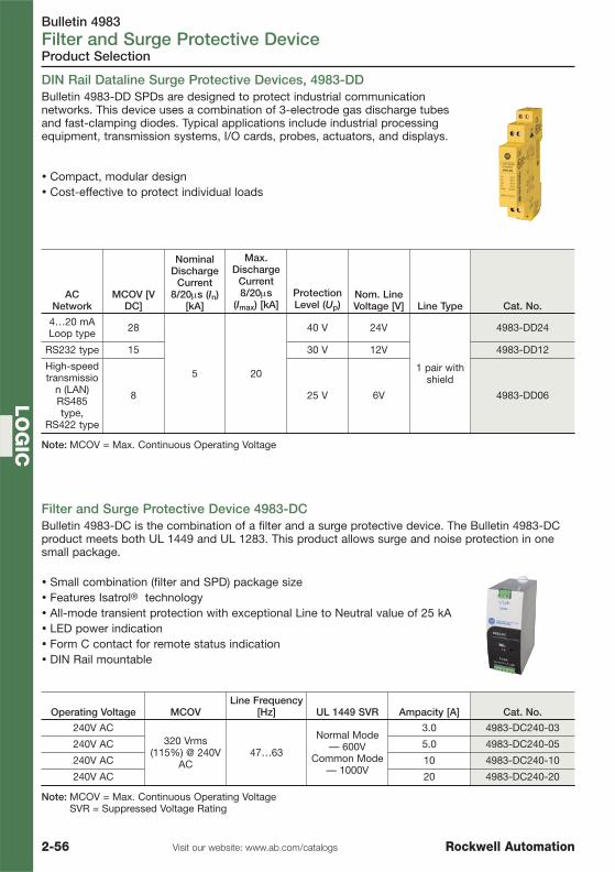
Bulletin 4983Filter and Surge Protective Device
2-56 Visit our website: www.ab.com/catalogs Rockwell Automation
LO
GIC
DIN Rail Dataline Surge Protective Devices, 4983-DD
Filter and Surge Protective Device 4983-DCBulletin 4983-DC is the combination of a filter and a surge protective device. The Bulletin 4983-DCproduct meets both UL 1449 and UL 1283. This product allows surge and noise protection in onesmall package.
� Small combination (filter and SPD) package size� Features Isatrol® technology� All-mode transient protection with exceptional Line to Neutral value of 25 kA� LED power indication� Form C contact for remote status indication� DIN Rail mountable
Operating Voltage MCOVLine Frequency
[Hz] UL 1449 SVR Ampacity [A] Cat. No.
240V AC320 Vrms
(115%) @ 240VAC
47…63
Normal Mode— 600V
Common Mode— 1000V
3.0 4983-DC240-03
240V AC 5.0 4983-DC240-05
240V AC 10 4983-DC240-10
240V AC 20 4983-DC240-20
Note: MCOV = Max. Continuous Operating VoltageSVR = Suppressed Voltage Rating
Product Selection
Bulletin 4983-DD SPDs are designed to protect industrial communicationnetworks. This device uses a combination of 3-electrode gas discharge tubesand fast-clamping diodes. Typical applications include industrial processingequipment, transmission systems, I/O cards, probes, actuators, and displays.
� Compact, modular design� Cost-effective to protect individual loads
ACNetwork
MCOV [VDC]
NominalDischarge
Current8/20μs (In)
[kA]
Max.Discharge
Current8/20μs
(Imax) [kA]ProtectionLevel (Up)
Nom. LineVoltage [V] Line Type Cat. No.
4…20 mALoop type 28
5 20
40 V 24V
1 pair withshield
4983-DD24
RS232 type 15 30 V 12V 4983-DD12
High-speedtransmissio
n (LAN)RS485type,
RS422 type
8 25 V 6V 4983-DD06
Note: MCOV = Max. Continuous Operating Voltage

Bulletin 1606, 1609, 1497Power Supplies, Control Circuit Transformers
2-57Visit our website: www.ab.com/catalogsRockwell Automation
LO
GIC
Product Line Overview
Switched Mode Power Supplies
Bulletin 1606-XLP 1606-XL 1606-XLS 1606-XLE
TypeSwitched Mode Power Supply
Single/Dual-Phase
Switched Mode Power Supply
Single/Three-Phase
Switched Mode Power Supply
Single/Three-Phase
Switched Mode Power SupplySingle-Phase
Output Power 15…100 W 60...960 W 80...960 W 80...240 W
Efficiency 80…90% 87…93% 91.6…95% 90…92%
Output Voltage/SecondaryVoltage
5, 10...12, 12, 15, 24,48V DC 24, 36, 48V DC 12…15, 24, 36…42,
48V DC 24, 48V DC
Rated OutputCurrent (24VDC)
1.3…4.2 A 2.5…40 A 3.4…40 A 5…10 A
OperatingTemperatureRange
-10…+70°C>60°C with derating
-10…+70°C>60°C with derating
-25…+70°C>60°C with derating
-25…+70°C>60°C with derating
Non-OperatingTemperatureRange
-40…+85°C
Certifications cULs, CE cULs, CE cULs, CE cULs, CE
Standards
EN 50081-1, EN 61000-6-2,
EN 61000-3-2 (A14)UL 508
UL 60950, CAN/CSA C22.2 No.
60950
EN 55011 (Class B), EN 55022 (Class B),
EN 61000-6-2, EN 61000-3-2 (A14),
EN 50081-1UL 508
UL 60950,CAN/CSA C22.2 No.
60950
EN 55011 (Class B), EN 55022 (Class B),
EN 61000-6-2, EN 61000-3-2 (A14),
EN 50081-1UL 508UL 1950
EN 55011 (Class B), EN 55022 (Class B),
EN 61000-6-2, EN 61000-3-2 (A14),
EN 50081-1UL 508UL 1950
SpecialApplicationProducts
- Compact redundancy module for 10…60V DC - Redundant power supplies- Buffer module for extended ride-through - DC UPS- Redundancy modules - DC converter
ProductSelection See page 2-59 See page 2-59 See page 2-59 See page 2-59
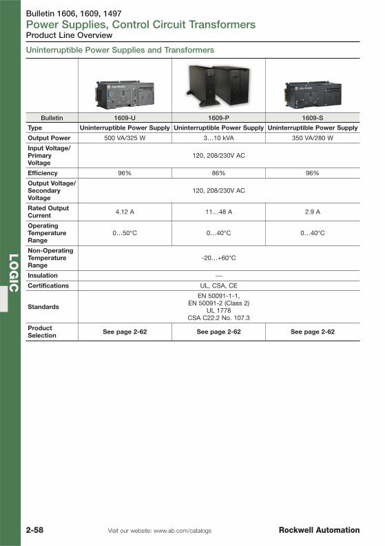
Bulletin 1606, 1609, 1497Power Supplies, Control Circuit Transformers
2-58 Visit our website: www.ab.com/catalogs Rockwell Automation
LO
GIC
Product Line Overview
Uninterruptible Power Supplies and Transformers
Bulletin 1609-U 1609-P 1609-S
Type Uninterruptible Power Supply Uninterruptible Power Supply Uninterruptible Power Supply
Output Power 500 VA/325 W 3…10 kVA 350 VA/280 W
Input Voltage/PrimaryVoltage
120, 208/230V AC
Efficiency 96% 86% 96%
Output Voltage/SecondaryVoltage
120, 208/230V AC
Rated OutputCurrent 4.12 A 11…48 A 2.9 A
OperatingTemperatureRange
0…50°C 0…40°C 0…40°C
Non-OperatingTemperatureRange
-20…+60°C
Insulation ⎯
Certifications UL, CSA, CE
Standards
EN 50091-1-1, EN 50091-2 (Class 2)
UL 1778CSA C22.2 No. 107.3
ProductSelection See page 2-62 See page 2-62 See page 2-62

Bulletin 1606Power Supplies
2-59Visit our website: www.ab.com/catalogsRockwell Automation
LO
GIC
Single Phase Power Supplies
Product Selection
Power Supplies 1606� Low inrush current� PFC choke� Wide range input; auto select input� Superior overload design (continuous current, no hiccup)� NEC Class 2 'Limited Power' option� Selectable operating mode (single/parallel)� Superior efficiency and temperature rating
OutputPower
[W]
OutputVoltage[V DC]
OutputCurrent
[A] Input Voltage Special Features
ParallelOperation(inclinedCharact.)
Meets EN61000-3-2
(PFCHarmonics) Cat. No.
1606-XLP Compact Single Phase
155…5.5 3
100…240V AC,85…375V DC
NEC Class 2
Yes ⎯ 1606-XLP15A12…15 1.3 Yes ⎯ 1606-XLP15B24…28 0.6 Yes ⎯ 1606-XLP15E
25 5…5.5 5 Yes NA 1606-XLP25A
3010…12 3 Yes NA 1606-XLP30B24…28 1.3 Yes NA 1606-XLP30E
36 +/- 12/15V 2.8 Adjustable outputvoltage NEC Class 2
No ⎯ 1606-XLP36C
50
12…15 4.2 Yes NA 1606-XLP50B24…28 2.1
NEC Class 2Yes NA 1606-XLP50E
24…28 2.1 Yes NA 1606-XLP50EZ48…56 1 Yes NA 1606-XLP50F
72 24…28 3 100…120/220…240V AC,
220…375V DCNEC Class 2
Yes NA 1606-XLP72E
90 12…15 7.5 Yes Yes 1606-XLP90B
95 24…28 3.9 100…200/200…240V AC,
220…375V DC
NEC Class 2 No Yes 1606-XLP95E
10024…28 4.2 ⎯ Yes � Yes 1606-XLP100E48…56 2.1 ⎯ Yes � Yes 1606-XLP100F
1606-XL Standard Single Phase
60 24 2.5100…120/200…
240V AC,160…375V DC
NEC Class 2 Yes — 1606-XL60D
180 12…15 15100…200/200…
240V AC,240…375V DC
— Yes — 1606-XL180B
48024…28 20
200…240V AC,270…370V DC
Active inrush currentlimiting Yes � — 1606-XL480E
100…120/200…240V AC
— Yes � — 1606-XL480EPRemote shut down Yes � — 1606-XL480EPT
36…43 13.3 — Yes � — 1606-XL480GP48…56 10 — Yes � — 1606-XL480F
1606-XLE Essential Single Phase80 24…28 3.3 100…120/200…
240V AC— No Yes 1606-XLE80E
120 24…28 5Auto-select input No — 1606-XLE120E
180…264V AC 200…240V AC only No — 1606-XLE120EE
24024…28 10
100…120/200…240V AC Auto-select input No — 1606-XLE240E
180…264V AC 200…240V AC only No — 1606-XLE240EE
100…120/200…240V AC
— No — 1606-XLE240EP48…52 5 Auto-select input No — 1606-XLE240F
� Single/parallel operation (inclined characteristic) selectable (jumper)

Bulletin 1606Power Supplies
2-60 Visit our website: www.ab.com/catalogs Rockwell Automation
LO
GIC
Product Selection
Single Phase Power Supplies, continued
Two Phase Power Supplies
OutputPower [W]
OutputVoltage
OutputCurrent [A] Input Voltage Special Features
Parallel Operation(inclined Charact.) Cat. No.
1606-XLP Compact Two Phase90 24…28 3.75 380…480V AC NEC Class 2 No 1606-XLP90E-2100 24…28 4.2 380…480V AC — Yes 1606-XLP100E-2
1606-XLE Essential Two Phase
120 24…28 5 380…480V AC,600V DC — Yes 1606-XLE120E-2
Three Phase Power Supplies
OutputPower
[W]OutputVoltage
OutputCurrent
[A] Input Voltage Special Features
ParallelOperation(inclinedCharact.) Cat. No.
1606-XL Standard Three Phase120
24…28
5400…500V AC,450…820V DC
— Yes 1606-XL120E-3
240 10Overload behavior selectable (FUSEmode/continuous current), 2-phase
operation admissibleYes 1606-XL240E-3
480
20 480V AC,550…820V DC — Yes 1606-XL480E-3
20 400…500V AC,450…820V DC
Wide input range; overload behaviorselectable (FUSE mode/continuous
current)Yes 1606-XL480E-3W
48…56 10 400V AC,450…700V DC Input voltage 400V AC Yes 1606-XL480F-3H
720 24…28 30 400…500V AC,450…820V DC — Yes 1606-XL720E-3
960 24…28 40 400…500V AC
Passive load sharing Yes 1606-XL960E-3
Active inrush current limiting; outputsignals
Activecurrentsharing
1606-XL960E-3S
1606-XLE Essential Three Phase
240 24…28 10 380…480V AC,600V DC — Yes 1606-XLE240E-3
1606-XLS Performance Three Phase
48024…28 20
380…480V AC,600V DC
— Yes 1606-XLS480E-348…56 10 — Yes 1606-XLS480F-336…42 13.3 — Yes 1606-XLS480G-3
� Single/parallel operation (inclined characteristic) selectable (jumper)
OutputPower [W]
OutputVoltage
OutputCurrent [A] Input Voltage Special Features
Parallel Operation(inclined Charact.) Cat. No.
1606-XLS Performance Single Phase80
24…283.3
100…240V AC,110…300V DC
— Yes 1606-XLS80E120 5 — Yes 1606-XLS120E180 12…15 15 — Yes 1606-XLS180B
24024…28 10 — Yes 1606-XLS240E48…56 5 — Yes 1606-XLS240F28…32 8 — Yes 1606-XLS240K
480
24…28 20 — Yes 1606-XLS480E24…28 20 Conformal Coating Yes 1606-XLS480EC24…28 20 200…240V AC — Yes 1606-XLS480EE48…56 10 100…240V AC,
110…300V DC— Yes 1606-XLS480F
36…42 13.3 — Yes 1606-XLS480G

Bulletin 1606Power Supplies
2-61Visit our website: www.ab.com/catalogsRockwell Automation
LO
GIC
Product Selection / Accessories
AccessoriesDescription Cat. No.
Back-of-panel bracket for XL 1606-XLA
Back-of-panel bracket for XLS or XLE 1606-XLB
7 Ah/12V battery assembly with bracket, for use with DC UPS 1606-XLSBATASSY1
26 Ah/12V battery assembly with bracket, for use with DC UPS 1606-XLSBATASSY2
7 Ah/12V battery 1606-XLSBAT1
26 Ah/12V battery 1606-XLSBAT2
Output Power [W] Output Voltage Output Current [A] Description Cat. No.
240 22.5…30 10 UPS / external battery 1606-XLS240-UPS
240 22.5…30 10 UPS / internal battery 1606-XLS240-UPSC
DC - UPS's
Power Supplies 1606, continued
OutputPower
[W]OutputVoltage
OutputCurrent
[A] Input Voltage Special Features
ParallelOperation(inclinedCharact.)
Meets EN61000-3-2
(PFCHarmonics) Cat. No.
1606-XL Special Modules
— 23…27.8 20
24…28.8V DC Brownout buffermodule
— NA 1606-XLBUFFER
480 22.5…27.8 20 Yes NA 1606-XLSBUFFER24
960 45…54 20 48…56V DC Yes NA 1606-XLSBUFFER4840 5.1 8 18…36V DC DC/DC converter Yes NA 1606-XLDC40A
91 24 3.8100…240V
AC,110…300V DC
DeviceNet approved,electronically limited
3.8 ANo Yes 1606-XLSDNET4
192 24 8DeviceNet approved,electronically limited
8 AYes No 1606-XLSDNET8
60
24
2.5100…120/200…240V AC,
160…375V DC N+1 Redundantcapable , NEC Class 2
‡
Yes � NA 1606-XL60DR
120 5100…120/200…240V AC,
210…375V DCYes � Yes 1606-XL120DR
240 10100…120/200…240V AC,
240…375V DC
N+1 Redundantcapable ‡ Yes � No 1606-XL240DR
384Vin 1 -.9V typ
1610…60V DC
Compact redundancy10…60 V DC � — NA 1606-XLPRED
48020 Compact redundancy
10-60 V DC — — 1606-XLSRED
20 24…60V DC — — — 1606-XLERED
720Vin -.5V
typ
3024V DC
Dual 1+1 redundancy�
— NA 1606-XLRED20-30
960 40 Single N+1redundancy § — NA 1606-XLRED40
� Single/parallel operation (inclined characteristic) selectable (jumper)
� To be used alongside 20 and 30 A power supplies (or smaller)‡ Used with a pair of identical power supplies to offer N+1 redundancy§ To be used alongside 40 A power supplies (or smaller)

Bulletin 1609Power Supplies
2-62 Visit our website: www.ab.com/catalogs Rockwell Automation
LO
GIC
Product Selection
Uninterruptible Power SuppliesBulletin 1609-U Series� Rugged industrial design � Dry Contact I/O� DIN Rail mountable or
back-of-panel mountable� Elevated temperature
performance (up to 50°C)� Remote
monitoring/configuration� Comprehensive network
management� Line interactive � Pure sine wave output
Output Power Input VoltageTemperature,
operating
Without NetworkManagement Card
With NetworkManagement Card
Cat. No. Cat. No.
500VA (325 W)120V AC
0…40 °C 1609-U500NS 1609-U500NSC0…50 °C 1609-U500NH 1609-U500NHC
208/230V AC0…40 °C 1609-U500ES 1609-U500ESC0…50 °C 1609-U500EH 1609-U500EHC
Output Power Input Voltage Cat. No.3000VA (2100 W) 208V AC 1609-P3000H3000VA (2100 W) 120V AC 1609-P3000N3000VA (2100 W) 230V AC 1609-P3000A5000VA (3500 W) 208/230V AC 1609-P5000E8000VA (6400 W) 208/230V AC 1609-P8000E
10000VA (8000 W) 208/230V AC 1609-P10000E
Bulletin 1609-P Series� Rugged industrial design � Remote monitoring/configuration� Tower/Rack compatible � Double conversion online� Extended runtime � Pure sine wave output� Battery management system � Frequency and voltage regulation� Hot swappable batteries � Automatic internal bypass� Comprehensive network management
Bulletin 1609-S Series� DIN Rail mountable or
back-of-panel mountable� Intelligent battery
management system� Line interactive � Serial communication� Pure sine wave output
Output Power Input Voltage Cat. No.350VA (280 W) 120V AC 1609-S350NS350VA (280 W) 208/230V AC 1609-S350ES
1609 Accessories
Description Output Power For Use With Series Cat. No.40 °C replacement battery 500VA (325 W) U, S 1609-500SBAT50 °C replacement battery 500VA (325 W) U 1609-500HBATNetwork management card U, P 1609-NMCRemote start cable U, P, S 1609-RSCReplacement battery P 1609-PBATExternal battery pack P 1609-PXBP5000VA CCT (120V step down transformer) P 1609-5000CCTRail kit P 1609-PRK1DIN Rail kit S 1609-SDK1Dry contact I/O communication cable S 1609-SDC1Hardwire kit (for 3 and 5 kVA units) P 1609-HDK1Service bypass switch (16 kVA) P 1609-PSB1

Visit our website: www.ab.com/catalogsRockwell Automation 3-1
TABLE OF CONTENTS
Operator InterfaceOperator Interface
Control and Indicating Units 3-2
Graphic Terminals and Message Displays 3-42

Bulletin 800FControl and Indicating Units
3-2 Visit our website: www.ab.com/catalogs Rockwell Automation
OP
ER
AT
OR
INT
ER
FAC
E
Product Line Overview
Bulletin 800F 800F 800F 800F 800FC 800FD
Description Push ButtonsEmergency
StopOperators
SelectorSwitches Pilot Lights Pendant
StationsMonolithic
Push Buttons
MountingHole Size 22.5 mm
Features
� Flush,Extended,Guarded,Mushroom &JumboMushroom,andLegendedVersions
� Illuminated,Non-Illuminated
� Push-Pull &Twist-to-Release
� Illuminated,Non-Illuminated &KeyedOperators
� Illuminated,Non-Illuminated &KeyedOperators
� StandardDiffuser,OpticallyEnhanced,IntegratedLED
� LED andIncandescent Lamps
� 3-, 5-, 7-,and 9-holeenclosures
� Usesstandard800Foperators
� 1-, 2-, and3-speedoperators
� Mechanicaland/orelectricalinterlockavailable
� E-Stop� 2/3-
PositionsSelectorSwitch
� MomentaryPushButtons
� Pilot Light
MountingMethod Back of Panel Mtg. Ring
Material &Degree ofProtection
800FM: Metal, Type 4/13, IP65/66800FP: Plastic, Type 4/4X/13, IP65/66
PlasticIP66, NEMAType 4/4X/13
800FD: Plastic,Type IP66
Maximum #of Circuits
Illum: 3-Across - 4 CircuitsNon-Illum: 6 Circuits — — —
Approvals UL, UR, CSA, CCC, CE UL, CSA, CCC,CE
OperatingTemperature –25…+70 °C –25…+60 °C
Design Life10 M
MechanicalCycles
100 KMechanical
Cycles
300 KMechanical
Cycles
Incandescent: 5K-20K
Hrs. LED: 100KHrs.
—
Incandescent: 5K-20K
Hrs. LED: 100KHrs.
ContactBlock &PowerModuleAssembly
Field Assembly No Assembly
ProductSelection
See page 3-7,page 3-9
See page 3-8,page 3-18
See page 3-8,page 3-14
See page 3-7,page 3-11 See page 3-28 See page 3-11
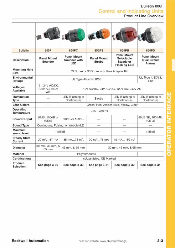
Bulletin 800FControl and Indicating Units
3-3Visit our website: www.ab.com/catalogsRockwell Automation
OP
ER
AT
OR
IN
TE
RFA
CE
Product Line Overview
Bulletin 855P 855PC 855PS 855PB 855PD
Description Panel MountSounder
Panel MountSounder with
LED
Panel MountStrobe
Panel MountSelectableSteady or
Flashing LED
Panel MountDual Circuit
Alarms
Mounting HoleSize 22.5 mm or 30.5 mm with Hole Adapter Kit
EnvironmentalRatings UL Type 4/4X/14, IP65 UL Type 4/4X/13,
IP65
VoltagesAvailable
12…24V AC/DC,120V AC, 240V
AC12V AC/DC, 24V AC/DC, 120V AC, 240V AC
IlluminationType — LED (Flashing or
Continuous) Strobe LED (Flashing orContinuous)
LED (Flashing orContinuous)
Lens Colors — Green, Red, Amber, Blue, Yellow, Clear
OperatingTemperature –25…+60 °C
Sound Output 80dB, 100dB or105dB 98dB or 103dB — — 80dB SE, 100 ME,
105 LE
Sound Type Continuous, Pulsing, or Wobble (LE) — — —
Minimumsound level <85dB — — < 85dB
Steady StateCurrent 20 mA…57 mA 35 mA…73 mA 20 mA…75 mA 10 mA…150 mA —
Diameter 30 mm, 45 mm, &65 mm 45 mm, & 65 mm 30 mm, 45 mm, & 65 mm
Material Polycarbonate
Certifications cULus listed, CE Marked
ProductSelection See page 3-30 See page 3-30 See page 3-31 See page 3-30 See page 3-31

Bulletin 800FControl and Indicating Units
3-4 Visit our website: www.ab.com/catalogs Rockwell Automation
OP
ER
AT
OR
INT
ER
FAC
E
Product Line Overview
Bulletin 855T 855E 855D
Description Control Tower™Stack Lights 70 mm
Control Tower™Stack Lights 50 mm
Control Tower™Stack Lights 30 mm
EnvironmentalRatings
� UL Type 4/4X/13 on all bases,lights piezo style sound andcaps (sound and light withsound combo modules are ULType 12, IP54)
� Indoor and outdoor use� IP65
� UL Type 4/4X/13 on allbases, lights and capssound modules
� Indoor and outdoor use� IP65
� UL Type 4/4X/13� Indoor and outdoor use� IP65
Ease ofAssembly,Base Wiringand LampChanges
No-tools assemby, “Twist-off”lenses for easy lamp changes,top-mounted terminal block foreasy base wiring
No-tools assembly, “Twist-off” lenses for easy lampchanges, top-mountedterminal block for easy basewiring
No assembly required - alltowers are assembled, wired,and tested at the factory
IlluminationTypes Incandescent, socket-mount LED, or strobe LED
Lens Colors Green, Red, Amber, Blue, Yellow, Clear
Pole-MountBase Options
10, 25, 40, 60, and 80 cm –aluminium or stainless steel bases
10, 25, 40, 60, and 80 cmbases
Surface, 10 cm metric tube,and 25 cm metric tube
Other BaseMountingOptions
Surface-mount bases (surface-mount bases also feature 1/2NPT,
PG16 threading options)Vertical-mount bases
Surface-mount bases(surface-mount bases alsofeature 1/2NPT, PG16 and
M20 threading options)Vertical-mount bases
Vertical bracket and conduitadapter
Base Colors Black or grey base housing
Sound Options
Transducer style or Piezo stylesound modules available in singleor dual tone (sound modules areUL Type 12, IP54), Piezo Styles
and modules also available in 4/4X
Piezo style sound modules in single and dual tone
NetworkConnectivity
Standard or DeviceNetconnectivity Standard connectivity Standard connectivity
VoltagesAvailable
All modules available in: 12V/24VAC/DC, 120V AC, 240V AC as
standard offerings
All modules available in: 12V/24V AC/DC, 120V AC, 240V
AC as standard offerings
Bases available in: 24VAC/DC, 240V AC as standard
offerings
Junction Box Surface, Vertical, and Magnetic Mount
Certifications cULus Listed and CE on all components cULus Listed, CE marked
OperatingTemperature –25…+70°C –25…+50°C
MaterialPolycarbonate - Bases, Cap, Lens
Cover, Sound Module Housing,Lens, & Lamp Socket
Polycarbonate (no soundmodule) - Bases, Cap, LensCover, Lens, & Lamp Socket
Polycarbonate - Bases, Cap,Lens Cover, Sound Module
Housing, Lens, & LampSocket
ProductSelection See page 3-32 See Publication
A116See Publication 855D-PP001…

Bulletin 800FControl and Indicating Units
3-5Visit our website: www.ab.com/catalogsRockwell Automation
OP
ER
AT
OR
IN
TE
RFA
CE
Product Line Overview
Bulletin 855F 855H 855B
DescriptionPre-assembled and Pre-
wired Tower Lights70 mm
General Purpose Hornsand High PerformanceHorns (with or without
Beacons)
Mini Square Beacons
Environmental Ratings � UL Type 4/4X/13� IP65
� IP56/Type 13 &13R� (Horn w/Beacon:
IP56/Type 13)� IP66/Type 13
Voltages AvailableBases available in: 24V
AC/DC, 240V AC asstandard offerings
10-30V DC, 24V AC 50/60Hz, 110V AC 50/60 Hz,
230V AC 50/60 Hz
12V AC/DC, 24V AC/DC,110V AC 50/60Hz, 230V
AC 50/60 Hz
Voltages Available (Hornw/Beacon) —
12V DC, 24V DC, 24V AC50/60 Hz, 110V AC 50/60
Hz, 230V AC 50/60 Hz—
Illumination Type LED Strobe 5 Joule
Flash Rate — — 1 Hz
Lens Colors Green, Red, Amber, Blue, Yellow, Clear
Pole-Mount Base Options
Surface, 10 cm metrictube, and 25 cm metric
tube Vertical-mount bases
— —
Operating Temperature –25 … +60 °C –25 … +55 °C
Steady State Current — —
12V AC/DC (400/500mA),24V AC/DC (365/250 mA),110V AC (100mA), 230V
AC (50 mA)
Base Colors Black or grey housing — —
Sound Options Piezo style sound modulesin single and dual tone
Output Level: 100 dB – 126dB —
Range —
10 Tones Range, A Horn 32 Tones Range, B & C
Horn45 Tones Range, D & E
—
Network Connectivity Standard connectivity — —
Volume Adjustable —16 dB from max. Range A,
B, C6 dB from max. Range D, E
—
Circuits Available —
Range A – 2 on DC units, 1on AC units
Range B, C, D, E - 3 on allunits
—
Material
Polycarbonate - Bases,Cap, Lens Cover, SoundModule Housing, Lens, &
Lamp Socket
Polycarbonate - Horn Cover, Base, Beacon Housing andLens
Certifications cULus Listed,CE marked cULus, CE
Product Selection See page 3-36 See page 3-37 See page 3-38
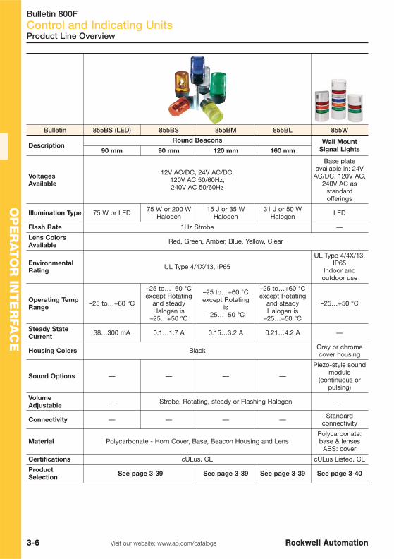
Bulletin 800FControl and Indicating Units
3-6 Visit our website: www.ab.com/catalogs Rockwell Automation
OP
ER
AT
OR
INT
ER
FAC
E
Product Line Overview
Bulletin 855BS (LED) 855BS 855BM 855BL 855W
DescriptionRound Beacons Wall Mount
Signal Lights90 mm 90 mm 120 mm 160 mm
VoltagesAvailable
12V AC/DC, 24V AC/DC, 120V AC 50/60Hz, 240V AC 50/60Hz
Base plateavailable in: 24V
AC/DC, 120V AC,240V AC as
standardofferings
Illumination Type 75 W or LED 75 W or 200 WHalogen
15 J or 35 WHalogen
31 J or 50 WHalogen LED
Flash Rate 1Hz Strobe —
Lens ColorsAvailable Red, Green, Amber, Blue, Yellow, Clear
EnvironmentalRating UL Type 4/4X/13, IP65
UL Type 4/4X/13,IP65
Indoor andoutdoor use
Operating TempRange –25 to…+60 °C
–25 to…+60 °Cexcept Rotating
and steadyHalogen is
–25…+50 °C
–25 to…+60 °Cexcept Rotating
is–25…+50 °C
–25 to…+60 °Cexcept Rotating
and steadyHalogen is
–25…+50 °C
–25…+50 °C
Steady StateCurrent 38…300 mA 0.1…1.7 A 0.15…3.2 A 0.21…4.2 A —
Housing Colors Black Grey or chromecover housing
Sound Options — — — —
Piezo-style soundmodule
(continuous orpulsing)
VolumeAdjustable — Strobe, Rotating, steady or Flashing Halogen —
Connectivity — — — — Standardconnectivity
Material Polycarbonate - Horn Cover, Base, Beacon Housing and LensPolycarbonate:base & lenses
ABS: cover
Certifications cULus, CE cULus Listed, CE
ProductSelection See page 3-39 See page 3-39 See page 3-39 See page 3-40

Bulletin 800FControl and Indicating Units
3-7Visit our website: www.ab.com/catalogsRockwell Automation
OP
ER
AT
OR
IN
TE
RFA
CE
Complete Units
Non-Illuminated Push Buttons, Momentary (Screw Terminal Connections)
Pilot Lights with Integrated LED Modules (Screw Terminal Connections)
Voltage Type Construction Cat. No.
24V AC/DC
Green
Plastic Pilot Light /Plastic Latch
800FP-P3PN3G
Red 800FP-P4PN3R
Yellow 800FP-P5PN3Y
Blue 800FP-P6PN3B
White 800FP-P7PN3W
240V AC
Green 800FP-P3PN7G
Red 800FP-P4PN7R
Yellow 800FP-P5PN7Y
Blue 800FP-P6PN7B
White 800FP-P7PN7W
24V AC/DC
Green
Metal Pilot Light /Metal Latch
800FM-P3MN3G
Red 800FM-P4MN3R
Yellow 800FM-P5MN3Y
Blue 800FM-P6MN3B
White 800FM-P7MN3W
240V AC
Green 800FM-P3MN7G
Red 800FM-P4MN7R
Yellow 800FM-P5MN7Y
Blue 800FM-P6MN7B
White 800FM-P7MN7W
Product Selection
Description
Type of Contact
Color Construction Cat. No.N.O. N.C.
Flush 1 —
Green Plasticoperator/plastic
latch
800FP-F3PX10
Black 800FP-F2PX10
Green Metaloperator/metal
latch
800FM-F3MX10
Black 800FM-F2MX10
Extended — 1 Red
Plasticoperator/plastic
latch800FP-E4PX01
Metaloperator/metal
latch800FM-E4MX01
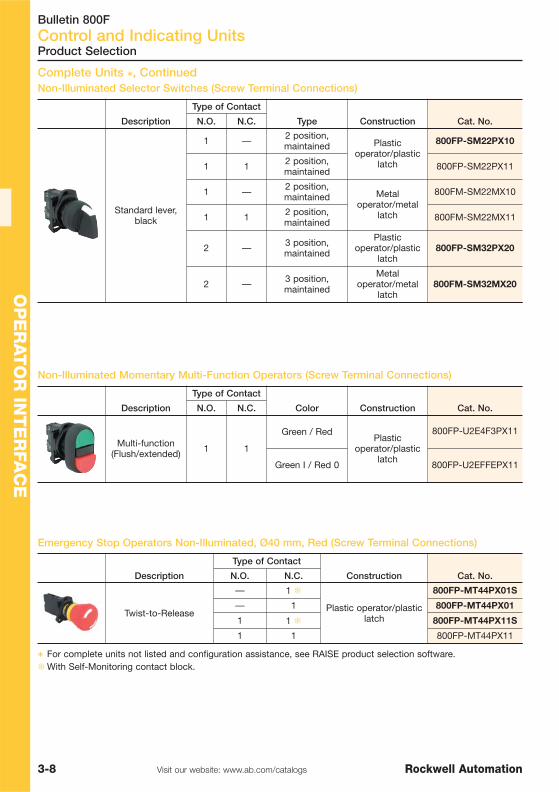
Bulletin 800FControl and Indicating Units
3-8 Visit our website: www.ab.com/catalogs Rockwell Automation
OP
ER
AT
OR
INT
ER
FAC
E
Product Selection
Complete Units �, ContinuedNon-Illuminated Selector Switches (Screw Terminal Connections)
Non-Illuminated Momentary Multi-Function Operators (Screw Terminal Connections)
Emergency Stop Operators Non-Illuminated, Ø40 mm, Red (Screw Terminal Connections)
Description
Type of Contact
Type Construction Cat. No.N.O. N.C.
Standard lever,black
1 — 2 position,maintained Plastic
operator/plasticlatch
800FP-SM22PX10
1 1 2 position,maintained 800FP-SM22PX11
1 — 2 position,maintained Metal
operator/metallatch
800FM-SM22MX10
1 1 2 position,maintained 800FM-SM22MX11
2 — 3 position,maintained
Plasticoperator/plastic
latch800FP-SM32PX20
2 — 3 position,maintained
Metaloperator/metal
latch800FM-SM32MX20
Description
Type of Contact
Color Construction Cat. No.N.O. N.C.
Multi-function(Flush/extended) 1 1
Green / RedPlastic
operator/plasticlatch
800FP-U2E4F3PX11
Green I / Red 0 800FP-U2EFFEPX11
Description
Type of Contact
Construction Cat. No.N.O. N.C.
Twist-to-Release
— 1 �
Plastic operator/plasticlatch
800FP-MT44PX01S
— 1 800FP-MT44PX01
1 1 � 800FP-MT44PX11S
1 1 800FP-MT44PX11
� For complete units not listed and configuration assistance, see RAISE product selection software.�With Self-Monitoring contact block.

Bulletin 800FControl and Indicating Units
3-9Visit our website: www.ab.com/catalogsRockwell Automation
OP
ER
AT
OR
IN
TE
RFA
CE
Flush Operator
Button Color Legend Text
Flush — Round
Plastic Metal
Cat. No. Cat. No.
Blue R 800FP-R611 800FM-R611
Button Color Text Color Legend
Extended
Plastic Metal
Cat. No. Cat. No.
Red WhiteSTOP 800FP-E402 800FM-E402
O 800FP-E405 800FM-E405
Black White → 800FP-E208 800FM-E208
Button Color Text Color Legend
Flush
Plastic Metal
Cat. No. Cat. No.
Green WhiteSTART 800FP-F301 800FM-F301
I 800FP-F306 800FM-F306
Black White → 800FP-F208 800FM-F208
Momentary Push Button Operators, Non-Illuminated — With Two-Color MoldedLegend Caps �
Reset Operator
Color
Flush Extended
Plastic Metal Plastic Metal
Cat. No. Cat. No. Cat. No. Cat. No.
Black 800FP-F2 800FM-F2 800FP-E2 800FM-E2
Green 800FP-F3 800FM-F3 800FP-E3 800FM-E3
Red 800FP-F4 800FM-F4 800FP-E4 800FM-E4
Product Selection
Flush Operator Extended Operator
Momentary Push Button Operators, Non-Illuminated — Flush, Extended
Reset Operators �
� For custom laser-engraved legend cap, order “no cap” option plus custom laser-engraved cap, see publication800F-SG001…
� For reset rods please refer to A116 catalogue

Bulletin 800FControl and Indicating Units
3-10 Visit our website: www.ab.com/catalogs Rockwell Automation
OP
ER
AT
OR
INT
ER
FAC
E
Product Selection
Momentary Push Button Operators, Illuminated — Flush, Extended �
Flush Operator Extended Operator
Color
Flush Extended
Plastic Metal Plastic Metal
Cat. No. Cat. No. Cat. No. Cat. No.
Green 800FP-LF3 800FM-LF3 800FP-LE3 800FM-LE3
Red 800FP-LF4 800FM-LF4 800FP-LE4 800FM-LE4
Yellow 800FP-LF5 800FM-LF5 800FP-LE5 800FM-LE5
Blue 800FP-LF6 800FM-LF6 — —
Clear 800FP-LF7 800FM-LF7 800FP-LE7 800FM-LE7
Alternate Action Operators, Non-Illuminated
Color
Plastic Metal
Cat. No. Cat. No.
Green 800FP-FA3 800FM-FA3
Red 800FP-FA4 800FM-FA4
Flush Operator
Alternate Action Operators, Illuminated
Color
Plastic Metal
Cat. No. Cat. No.
Green 800FP-LFA3 800FM-LFA3
Red 800FP-LFA4 800FM-LFA4
Flush Operator
� For custom laser-engraved operator, order operator with applicable lens cap color plus custom laser-engraveddiffuser, see publication 800F-SG001…

Bulletin 800FControl and Indicating Units
3-11Visit our website: www.ab.com/catalogsRockwell Automation
OP
ER
AT
OR
IN
TE
RFA
CE
Product Selection
Plastic Pilot Light Metal Pilot Light
Color
Plastic Metal
Cat. No. Cat. No.
Green 800FP-P3 800FM-P3
Red 800FP-P4 800FM-P4
Yellow 800FP-P5 800FM-P5
Clear 800FP-P7 800FM-P7
Amber 800FP-P0 800FM-P0
Lens & LED Color
Voltage
24V AC/DC 240V AC
Cat. No. Cat. No.
Green 800FD-P3N3 800FD-P3N7
Red 800FD-P4N3 800FD-P4N7
Yellow 800FD-P5N3 800FD-P5N7
Pilot Lights �
Lens Color
Voltage
24V AC/DC
Cat. No.
Green 800FD-P3D3
Red 800FD-P4D3
Yellow 800FD-P5D3
� For custom laser-engraved pilot light, order pilot light with applicable lens cap color plus custom laser-engraveddiffuser, see publication 800F-SG001…
800FD Monolithic Pilot Lights — LED
800FD Monolithic Pilot Lights — Incandescent
LED

Bulletin 800FControl and Indicating Units
3-12 Visit our website: www.ab.com/catalogs Rockwell Automation
OP
ER
AT
OR
INT
ER
FAC
E
Product Selection
800FD Monolithic 2-Position Push-Pull/Twist-to-Release Mushroom Operators,Non-Illuminated
Color Contacts Cat. No.
Red1 N.C. 800FD-MT44X01
2 N.C. 800FD-MT44X02
1 N.C., 1 N.O. 800FD-MT44X11
800FD Momentary Push Button Operators, Non-Illuminated
Operator Type Cap Color Text
Contact Configuration
1 N.O. 1 N.C. 1 N.O. & 1 N.C.
Cat. No. Cat. No. Cat. No.
Flush
Black — 800FD-F2X10 800FD-F2X01 800FD-F2X11
Green — 800FD-F3X10 800FD-F3X01 800FD-F3X11
Red — 800FD-F4X10 800FD-F4X01 800FD-F4X11
Green I 800FD-F306X11
Red O 800FD-F405X11
Green START 800FD-F301X11
Red STOP 800FD-F402X11
Blue R 800FD-F611X11
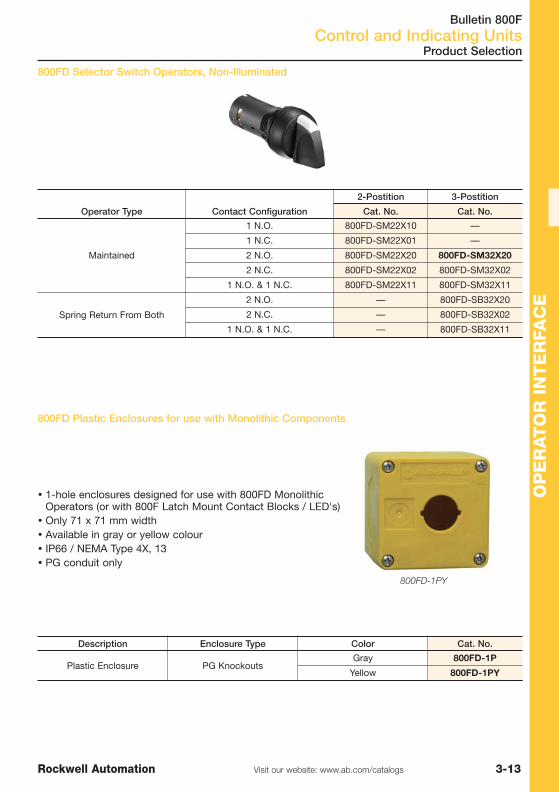
Bulletin 800FControl and Indicating Units
3-13Visit our website: www.ab.com/catalogsRockwell Automation
OP
ER
AT
OR
IN
TE
RFA
CE
OP
ER
AT
OR
IN
TE
RFA
CE
800FD Plastic Enclosures for use with Monolithic Components
Description Enclosure Type Color Cat. No.
Plastic Enclosure PG KnockoutsGray 800FD-1P
Yellow 800FD-1PY
� 1-hole enclosures designed for use with 800FD MonolithicOperators (or with 800F Latch Mount Contact Blocks / LED's)
� Only 71 x 71 mm width� Available in gray or yellow colour� IP66 / NEMA Type 4X, 13� PG conduit only
800FD-1PY
800FD Selector Switch Operators, Non-Illuminated
Operator Type Contact Configuration
2-Postition 3-Postition
Cat. No. Cat. No.
Maintained
1 N.O. 800FD-SM22X10 —
1 N.C. 800FD-SM22X01 —
2 N.O. 800FD-SM22X20 800FD-SM32X20
2 N.C. 800FD-SM22X02 800FD-SM32X02
1 N.O. & 1 N.C. 800FD-SM22X11 800FD-SM32X11
Spring Return From Both
2 N.O. — 800FD-SB32X20
2 N.C. — 800FD-SB32X02
1 N.O. & 1 N.C. — 800FD-SB32X11
Product Selection

Bulletin 800FControl and Indicating Units
3-14 Visit our website: www.ab.com/catalogs Rockwell Automation
OP
ER
AT
OR
INT
ER
FAC
EO
PE
RAT
OR
INT
ER
FAC
E
Illuminated Selector Switch Operators, 2-Positions �
Color
Operator Type Standard Knob
Plastic Metal
Cat. No. Cat. No.
Green 800FP-LSM23 800FM-LSM23
Red 800FP-LSM24 800FM-LSM24
Amber 800FP-LSM20 800FM-LSM20
Target Table and Operator Position �
SwitichingAngle
ContactType
N.O. O X
N.C. X O
Note: X = Closed/O = OpenStandard Knob
Target Table and Operator Position �
SwitchingAngle
ContactType
N.O. O X
N.C. X O
Note: X = Closed/O = Open
Product Selection
Non-Illuminated Selector Switches, 2-Positions
Color
Operator Type Standard Knob
Plastic Metal
Cat. No. Cat. No.
Black with White Insert 800FP-SM22 800FM-SM22
� Target table for spring return from left is reversed from what is shown in the table.� LED module required for illumination.
Standard Knob

Bulletin 800FControl and Indicating Units
3-15Visit our website: www.ab.com/catalogsRockwell Automation
OP
ER
AT
OR
IN
TE
RFA
CE
Target Table and Operator Position (Switching angle 60°), see publication800F-SG001…
Standard Knob Knob Lever
Color
Operator Type Standard Knob
Plastic Metal
Cat. No. Cat. No.
Black with White Insert800FP-SM32 800FM-SM32
800FP-SB32 800FM-SB32
Non-Illuminated Selector Switches, 3-Positions
Color
Operator Type Knob Lever
Plastic Metal
Cat. No. Cat. No.
Black with White Insert800FP-HM32 800FM-HM32
800FP-HB32 800FM-HB32
Product Selection
Non-Illuminated Selector Switches, 4 Positions
Color
Standard Knob — Maintained
Plastic Metal
Cat. No. Cat. No.
Black with White Insert 800FP-SM42 800FM-SM42
Standard Knob

Bulletin 800FControl and Indicating Units
3-16 Visit our website: www.ab.com/catalogs Rockwell Automation
OP
ER
AT
OR
INT
ER
FAC
EOperator Type Yellow
Plastic Metal
Cat. No. Cat. No.
800FP-LSM35 800FM-LSM35
800FP-LSR35 800FM-LSR35
800FP-LSL35 800FM-LSL35
800FP-LSB35 800FM-LSB35
� LED module required for illumination.
Operator Type Red
Plastic Metal
Cat. No. Cat. No.
800FP-LSM34 800FM-LSM34
800FP-LSR34 800FM-LSR34
800FP-LSL34 800FM-LSL34
800FP-LSB34 800FM-LSB34
Operator Type Green
Plastic Metal
Cat. No. Cat. No.
800FP-LSM33 800FM-LSM33
800FP-LSR33 800FM-LSR33
800FP-LSL33 800FM-LSL33
800FP-LSB33 800FM-LSB33
Product Selection
Target Table and Operator Position (Switching angle 60°), see publication 800F-SG001…
Illuminated Selector Switch Operators, 3-Positions �
Standard Knob

Bulletin 800FControl and Indicating Units
3-17Visit our website: www.ab.com/catalogsRockwell Automation
OP
ER
AT
OR
IN
TE
RFA
CE
Key Removal Position
Operator Type Key Selector Switch Operators
Plastic Metal
Cat. No. Cat. No.
Left 800FP-KM21 800FM-KM21
Both 800FP-KM23 800FM-KM23
Note: For Ronis replacement keys, see publication 800F-SG001…
Target Table and Operator Position
SwitchingAngle
ContactType
N.O. O X
N.C. X O
Note: X = Closed/O = Open
Product Selection
Key Operated Selector Switches, 2-Positions, Non-Illuminated ��
Key Selector Switch Key Selector Switch
Key Operated Selector Switches, 3-Positions, Non-Illuminated ��
Key Selector Switch Key Selector Switch
Key RemovalPosition
Operator Position Key Selector Switch Operators
Plastic Metal
Cat. No. Cat. No.
Left 800FP-KM31 800FM-KM31
All 800FP-KM33 800FM-KM33
Center 800FP-KM34 800FM-KM34
Center 800FP-KB34 800FM-KB34
Note: For Ronis replacement keys, see publication 800F-SG001…
� Keyed operators are IP66, Type 4/13.�Not intended for high security applications. Interoperability is possible with certain key/cylinder lock
combinations. Please consult your local sales office for interoperability information.
Target Table and Operator Position (Switching angle 60°), see publication800F-SG001…

Bulletin 800FControl and Indicating Units
3-18 Visit our website: www.ab.com/catalogs Rockwell Automation
OP
ER
AT
OR
INT
ER
FAC
EEmergency Stop 40 mm,
Non-Illuminated, Key Release
Key Release
Twist-to-Release, Push-Pull
Non-Illuminated
Emergency Stop Operators �
Product Selection
Emergency Stop 60 mm,Non-Illuminated, Twist-to-Release
Emergency Stop 40 mm,Non-Illuminated, Twist-to-Release
Color Size [mm]
Twist-to-Release (Trigger Action)
Plastic Metal
Cat. No. Cat. No.
Red
30 800FP-MT34 800FM-MT34
40 800FP-MT44 800FM-MT44
60 800FP-MT64 800FM-MT64
Color Size [mm]
Push-Pull (Trigger Action)
Plastic Metal
Cat. No. Cat. No.
Red 40 800FP-MP44 800FM-MP44
Color Size [mm]
Ronis Key Lock (Trigger Action)
Plastic Metal
Cat. No. Cat. No.Red 40 800FP-MK44 800FM-MK44
� All emergency stop operators are EN 418 compliant.

Bulletin 800FControl and Indicating Units
3-19Visit our website: www.ab.com/catalogsRockwell Automation
OP
ER
AT
OR
IN
TE
RFA
CE
Product Selection
Emergency Stop 40 mm,Illuminated, Twist-to-Release
Emergency Stop Operators, continued �
Illuminated
Twist-to-Release, Push-Pull �
Color Size [mm]
Twist-to-Release (Trigger Action)
Plastic Metal
Cat. No. Cat. No.
Red 40 800FP-LMT44 800FM-LMT44
Red 60 800FP-LMT64 800FM-LMT64
Color Size [mm]
Push-Pull (Trigger Action)
Plastic Metal
Cat. No. Cat. No.
Red
30 800FP-LMP34 800FM-LMP34
40 800FP-LMP44 800FM-LMP44
60 800FP-LMP64 800FM-LMP64
� All emergency stop operators are EN 418 compliant.� LED module required for illumination.
90 mm OperatorsPush-Pull (Trigger Action)
Color Size [mm]
Push-Pull (Trigger Action)
Plastic
Cat. No.
Black90
800FP-MP92
Red 800FP-MP94
Color Size [mm]
Push-Pull (Trigger Action)
Plastic
Cat. No.
Red 90 800FP-LMP94
90 mm Half Dome Mushroom Operators, Push-Pull, Non-Illuminated
90 mm Half Dome Mushroom Operators, Push-Pull, Illuminated
NEW

Bulletin 800FControl and Indicating Units
3-20 Visit our website: www.ab.com/catalogs Rockwell Automation
OP
ER
AT
OR
INT
ER
FAC
E
Product Selection
Momentary Push Button Operators, Non-Illuminated — Mushroom �
Color Size [mm]
Plastic Metal
Cat. No. Cat. No.
Black
40
800FP-MM42 800FM-MM42
Green 800FP-MM43 800FM-MM43
Red 800FP-MM44 800FM-MM44
Yellow 800FP-MM45 800FM-MM45
Red60
800FP-MM64 800FM-MM64
Yellow 800FP-MM65 800FM-MM65
Red90
800FP-MM94 —
Yellow 800FP-MM95 —
60 mm Jumbo Mushroom 40 mm Mushroom
Momentary Push Button Operators, Illuminated — Mushroom �
40 mm Mushroom
Color
40 mm Mushroom
Plastic Metal
Cat. No. Cat. No.
Green 800FP-LMM43 800FM-LMM43
Red 800FP-LMM44 800FM-LMM44
Yellow 800FP-LMM45 800FM-LMM45
� Momentary mushroom operators are IP65 rated.

Bulletin 800FControl and Indicating Units
3-21Visit our website: www.ab.com/catalogsRockwell Automation
OP
ER
AT
OR
IN
TE
RFA
CE
Product Selection
Position 1 of the latch (left positionwhen viewed from the back)corresponds to position C of theoperator. Position 2 of the latch (rightposition when viewed from the back)corresponds to position A of theoperator.
2-Function MomentaryMulti-Operator, Non-Illuminated
Position A Position C2-Function Multi-
Operator
Color Type Text Color Type Text Cat. No.
Red Extended
Blank
Green Flush
Blank 800FP-U2E4F3
O I 800FP-U2EFFE
STOP START 800FP-U2EBFA
2-Function Momentary Multi-Operator, Non-Illuminated �
2-Function Momentary Multi-Operator, Illuminated ��
Position 1 of the latch (left position whenviewed from the back) corresponds to positionC of the operator. Position 2 of the latch (rightposition when viewed from the back)corresponds to position A of the operator.Position 3 of the latch (center position) isreserved for the power module.
2-Function MomentaryMulti-Operator, Illuminated
Position A Position B Position C2-Function Multi-
Operator
Color Type Text Type Color Type Text Cat. No.
Red Extended
BlankWhite Pilot
Lights Green Flush
Blank 800FP-LU2E4F3
O I 800FP-LU2EFFE
STOP START 800FP-LU2EBFA
3-Function Momentary Multi-Operator, Non-Illuminated �
Position 1 of the latch (left position whenviewed from the back) corresponds to positionC of the operator. Position 2 of the latch (rightposition when viewed from the back)corresponds to position A of the operator.Position 3 of the latch (center position)corresponds to position B of the operator.
Position C
Position B
Position A
3-Function MomentaryMulti-Operator, Non-Illuminated
Position A Position B Position C3-Function Multi-
Operator
Color Type Text Color Type Text Color Type Text Cat. No.Green Flush Blank Red Extended Blank Green Flush Blank 800FP-U3F3F34
� No Type 13 rating.

Bulletin 800FControl and Indicating Units
3-22 Visit our website: www.ab.com/catalogs Rockwell Automation
OP
ER
AT
OR
INT
ER
FAC
E
Single Turn Potentiometer Assembly
Resistive Element Cat. No.
None (Operator Only)§ 800FP-POT
150 800FP-POT1
500 800FP-POT2
1000 800FP-POT3
2500 800FP-POT4
5000 800FP-POT5
10 000 800FP-POT6
§ The 800FP-POT is a complete operator assembly supplied without the resistive element, used withpotentiometers having a shaft diameter of 6.0 mm (0.23 in.) and a shaft length of 50.0 mm (1.97 in.), or a shaftdiameter of 6.4 mm (0.25 in.) and a shaft length of 22.5 mm (0.88 in.). This operator is used with Type "J"potentiometers only.
♣ Rated 300V AC/DC, 2 W max.� A latch is not needed.
Product Selection
Single Turn Potentiometer Assembly §♣�
Potentiometer Assembly

Bulletin 800FControl and Indicating Units
3-23Visit our website: www.ab.com/catalogsRockwell Automation
OP
ER
AT
OR
IN
TE
RFA
CE
Back-of-Panel Components
Product Selection
Description PQ Cat. No.
Metal Mounting LatchThese are zinc-plated, metal die cast mounting latches.Note: Sold only in multiples of 10. Order (quantity of) 10 to receive onepackage of 10 pieces.
10 800F-ALM
Note: Sold only in multiples of 100. Order (quantity of) 100 to receiveone package of 100 pieces. 100 800F-ALM-BP
Plastic Mounting LatchNote: Sold only in multiples of 10. Order (quantity of) 10 to receive onepackage of 10 pieces.
10 800F-ALP
Note: Sold only in multiples of 100. Order (quantity of) 100 to receiveone package of 100 pieces. 100 800F-ALP-BP
Contact BlockNote: Sold only in multiples of 10. Order(quantity of) 10 to receive one packageof 10 pieces. Latch not included.
N.O.
10
800F-X10
N.C. 800F-X01
N.O.E.M. 800F-X10E
N.C.L.B. 800F-X01L
Self-Monitoring 800F-X01S
N.O. low voltage —QuadCONNECT™ 800F-X10V
N.C. low voltage —QuadCONNECT™ 800F-X01V
Dual circuit of 2 N.O. 800F-X20D
Dual circuit of 2 N.C. 800F-X02D
Dual circuit of 1 N.O.-1 N.C. 800F-X11D
N.O. spring-clamp 800F-Q10
N.C. spring-clamp 800F-Q01
Note: Sold only in multiples of 100.Order (quantity of) 100 to receive onepackage of 100 pieces. Latch notincluded.
N.O.100
800F-X10-BP
N.C. 800F-X01-BP
Clear silicone Protective Boot used onilluminated and non-illuminated, flushand extended operators.
Flush push button 10 800F-AB7
Extended push button 10 800F-ABE7
3-position multi-function 10 800F-AUB1
2-position multi-function 10 800F-AUB2
PQ = Package Quantity

Bulletin 800FControl and Indicating Units
3-24 Visit our website: www.ab.com/catalogs Rockwell Automation
OP
ER
AT
OR
INT
ER
FAC
E
Product Selection
Description Cat. No.Incandescent ModuleFor use with pilot lights, push buttons, andmomentary mushroom operators.Note: Sold in multiples of 10. Order (quantityof) 10 to receive one package of 10 pieces.Latch not included.
No bulb 800F-D0C24V AC/DC 800F-D3C
120V AC/DC 800F-D5C
Integrated LED ModuleFor use with all illuminated devices. For bestresults, LED should match lens color. Foramber operators, use yellow LED.Note: Sold in multiples of 10. Order (quantityof) 10 to receive one package of 10 pieces.Latch not included.
24V AC/DC � 800F-N3x120V AC � 800F-N5x240V AC � 800F-N7x
24V AC/DC spring-clamp � 800F-Q3x120V AC spring-clamp � 800F-Q5x240V AC spring-clamp � 800F-Q7x
Base Mounted Contact BlockBase mounted contact blocks can be usedin plastic or metal enclosures.Note: Sold only in multiples of 10. Order(quantity of) 10 to receive one package of 10pieces. Latch not included.
N.O. 800F-BX10N.C. 800F-BX01
N.O.E.M. 800F-BX10EN.C.L.B. 800F-BX01L
N.O. low voltage —QuadCONNECT™ 800F-BX10V
N.C. low voltage —QuadCONNECT™ 800F-BX01V
N.O. spring-clamp 800F-BQ10N.C. spring-clamp 800F-BQ01
Base Mounted Integrated LED ModuleBase mounted modules can be used inplastic or metal enclosures. For bestillumination results, LED should match lenscolor.Note: Sold in multiples of 10. Order (quantityof) 10 to receive one package of 10 pieces.Latch not included.
24V AC/DC � 800F-BN3x120V AC � 800F-BN5x240V AC � 800F-BN7x
24V AC/DC spring-clamp � 800F-BQ3x120V AC spring-clamp � 800F-BQ5x
240V AC spring-clamp � 800F-BQ7x
Diode ModuleFor lamp checking circuits. Latch not included.
up to 250V AC 800F-XD7
Null BlockFor wire terminations only. up to 600V AC 800F-NX70
� To complete the cat. no., replace the x with one of the following letters for the desired color: Y = Yellow, R = Red, G = Green, B = Blue, W = White.
Replacement Lamps
Lamp Type Typical Current [mA] Voltage ANSI No. PQ Cat. No.
Full VoltageIncandescent
150 mA 6V AC/DC 755 10 800F-N65
80 mA 12V AC/DC 756 10 800F-N141
70 mA 24V AC/DC 757 10 800F-N157
50 mA 48V AC/DC 1835 10 800F-N48
22 mA 130V AC/DC 949 10 800F-N130
Neon 2 mA 240V AC — 10 800F-N240
PQ = Package Quantity

Bulletin 800FControl and Indicating Units
3-25Visit our website: www.ab.com/catalogsRockwell Automation
OP
ER
AT
OR
IN
TE
RFA
CE
Product Selection
Plastic Enclosure Metal Enclosure Pendant Station
Type
Pendants
Yellow Plastic (IP66, 4/4X/13)
Cat. No.
1 hole in face 800F-P15
2 holes in face 800F-P25
1 hole in bottom 800F-P35
1 hole in face / 1 hole in bottom 800F-P45
Type
Enclosures
Plastic (IP66, 4/4X/13) Metal — Die Cast (IP66, 4/13)
PG Knockouts Metric Knockouts PG Knockouts Metric Knockouts
Cat. No. Cat. No. Cat. No. Cat. No.
1-hole 800F-1PP 800F-1PM 800F-1MP 800F-1MM
2-hole 800F-2PP 800F-2PM 800F-2MP 800F-2MM
3-hole 800F-3PP 800F-3PM 800F-3MP 800F-3MM
4-hole 800F-4PP 800F-4PM — —
5-hole — — 800F-5MP 800F-5MM
6-hole 800F-6PP 800F-6PM — —
1-hole (Yellow) 800F-1YP 800F-1YM — —
Plastic and Metal Enclosures
Plastic Enclosures (Latch or Base Mounting)� Feed-through design� Accepts two-piece snap-in legends� One-hole enclosure accepts 60 mm emergency stop legends� UL Listed, CSA Certified
Metal Enclosures (Latch or Base Mounting)� Feed-through design� Accepts two-piece snap-in legends
Pendant Stations� Blank legend cap marking� Connector not included. For ordering information, see accessories in publication 800F-SG001…

Bulletin 800FControl and Indicating Units
3-26 Visit our website: www.ab.com/catalogs Rockwell Automation
OP
ER
AT
OR
INT
ER
FAC
E NEW
Product Selection
2-Hole Plastic Grey Enclosure with Options and 1 N.O./1 N.C. Contact
Options Cat. No.
START and STOP Push Buttons 800F-2PP1
1-Hole Plastic Grey Enclosure with Options and 1 NO Contact
Options Cat. No.
Black Push Button - No Text 800F-1PP1
"0-1" 2-Position Selector Switch 800F-1PP2
1-Hole Metal Enclosure
Contact Configuration
Twist-To Release Operator Key Release Operator
Cat. No. Cat. No.
1 N.C. 800F-1MM1 800F-1MM4
1 N.O. / 1 N.C. 800F-1MM2 800F-1MM5
2 N.C. 800F-1MM3 800F-1MM6
1-Hole Plastic Yellow Enclosure, Metric Knockouts
Contact Configuration
Twist-To Release Operator Key Release Operator
Cat. No. Cat. No.
1 N.C. 800F-1YM1 800F-1YM4
1 N.O. / 1 N.C. 800F-1YM2 800F-1YM5
2 N.C. 800F-1YM3 800F-1YM6
Assembled Stations
1-Hole Plastic Enclosurewith E-Stop Operator
1-Hole Plastic Yellow Enclosure, Metric Knockouts
Contact Configuration Operator Type Cat. No.
1 N.C.Push Pull Operator
90 mm
800F-1YM1HD
1 N.O. / 1 N.C. 800F-1YM2HD
2 N.C. 800F-1YM3HD

Bulletin 800FControl and Indicating Units
3-27Visit our website: www.ab.com/catalogsRockwell Automation
OP
ER
AT
OR
IN
TE
RFA
CE
Accessories
Type Description Cat. No. (Blank)
30 x 40 mm 2-piece snap-in plate and frame Black with white text 800F-11BE100
30 x 50 mm 2-piece snap-in plate and frame Black with white text 800F-12BE100
30 x 40 mm snap-in plate only Black with white text 800F-17BE100
30 x 50 mm snap-in plate only Black with white text 800F-18BE100
cText
Code Description
E112 EMERGENCY STOP
F112 ARRÊT D’URGENCE
G112 NOT AUS
T112 ARRESTO EMERGENZA
S112 PARADA DE EMERGENCIA
B112EMERGENCY STOP, ARRÊT D’URGENCE,
PARADA DE EMERGENCIA
M112NOT AUS, ARRESTO EMERGENZA,
ARRÊT D’URGENCE
D112 NOODSTOP
N112 NÖDSTOPP, EMERGENCY STOP
W112 NØDSTOPP, EMERGENCY STOP
A112 NØSTOP
L112 NEYÐARSTOPP, NEYÐARSTOPP
H112 NÖD-STOP, HÄTÄ-SEIS, NÖD-STOP
aSize
Code Description
15 60 mm round
16 90 mm round
Legend Plates �Emergency Stop Legend Plates
Legend Plates and Frames
See Publication 800F-SG001… for complete product information.
bColor
Code Description
Y Yellow (30 mm) �
YS Yellow (22.5 mm) ‡
22.5
mm
30 m
m
800F-15YS… 800F-15Y…
� Sold only multiples of 10. Order (quantity of) 10 toreceive one package of 10 pieces.
�Must be used with base mount contact blocks andtrim washer.
‡ Must be used with latch mounted contact blocksonly.
800F – 15 YS E112
a b c
Legend Plate Frame — 2-Piece Snap-In §
Type Cat. No. Type Cat. No.
30 x 40 mm 800F-110 30 x 60 mm 800F-200
30 x 50 mm 800F-120 Special multifunction 800F-400
§ Blank legends and frames sold only in multiples of 10. Order (quantity of) 10 to receive one package of 10pieces. Legends with standard text/symbols or custom text are packaged in quantities of 1.

Bulletin 800FCControl and Indicating Units
3-28 Visit our website: www.ab.com/catalogs Rockwell Automation
OP
ER
AT
OR
INT
ER
FAC
E
Bulletin 800FC — Configured Pendant Stations
Product Selection
Enclosure Type Description Cat. No.3-hole
Pendants — YellowPlastic IP66 �
� 800FC-3Z5-hole ‡ 800FC-5Z7-hole ‡ 800FC-7Z9-hole ‡ 800FC-9Z
� Housings supplied with cabel sleeve, hanger ring, cable clamp, wire guides, and gasket.�Operator in position 1 is mounted horizontally. Operators in positions 2 and 3 are mounted vertically.‡ All operators are mounted horizontally.
1-, 2-, and 3-Speed Operators 800FP – C A 1 U243
a b ca
Operator TypeCode Description Code Description
A 1-speed single arrow B 2-speedD 1-speed double arrow C 3-speed �
bCap Color
Code Description1 White2 Black
cSymbol
Valid withTable a
Selections:
Description�
CodeVertical Mounting
CodeHorizontal Mounting
Black White Black WhiteA, B, C U100 Blank Blank U100 Blank Blank
One-Speed Operators
AU241 DOWN UP U243 RIGHT LEFTU244 REVERSE FORWARD U246 FORWARD REVERSEU700 LEFT RIGHT U700 UP DOWN
D
U261 DOWN FAST UP FAST U263 RIGHT FAST LEFT FASTU264 REVERSE FAST FORWARD FAST U266 FORWARD FAST REVERSE FAST
U260 LEFT FAST RIGHT FAST U260 UP FAST DOWN FAST
Two-Speed Operators
BU271 2-speed DOWN 2-speed UP U273 2-speed RIGHT 2-speed LEFTU274 2-speed REVERSE 2-speed FORWARD U276 2-speed FORWARD 2-speed REVERSEU270 2-speed LEFT 2-speed RIGHT U270 2-speed UP 2-speed DOWN
Three-Speed Operators
CU291 3-speed DOWN 3-speed UP U293 3-speed RIGHT 3-speed LEFTU294 3-speed REVERSE 3-speed FORWARD U296 3-speed FORWARD 3-speed REVERSEU290 3-speed LEFT 3-speed RIGHT U290 3-speed UP 3-speed DOWN
Cat. No. 800FC-3Z Cat. No. 800FC-7Z
Note: Please see page 3-29 for proper contact block configurations.� Text (DOWN, UP, LEFT, etc.) indicates arrow direction. Text is not printed on operators.
�Proper contact block assembly of these devices is required. Please see contact block information on page 3-29.

Bulletin 800FCControl and Indicating Units
3-29Visit our website: www.ab.com/catalogsRockwell Automation
OP
ER
AT
OR
IN
TE
RFA
CE
1-, 2-, and 3-Speed Contact Block Assemblies
Product Selection / Accessories
Operator Type Interlock TypeComposite
Cat. No.
1-speed
None 800F-PX10E
Electrical 800F-PX11C
Mechanical� 800F-LX20C
Electrical & Mechanical� 800F-LX22C
2-speed
None 800F-PX20C
Electrical 800F-PX21C
Mechanical� 800F-LX40C
Electrical & Mechanical� 800F-LX42C
3-speedNone § 800F-PX30C
Mechanical� § 800F-LX60C
�When ordering separate components, two pieces of each contact block must be ordered, one for each operator.§ Contact blocks come preassembled onto latch.
Accessories
Description PQ Cat. No.
Mechanical interlock latch 1�
800FC-ALP
Replacement wire guide 2 800FC-AWG
Insulated side jumper50 1492-SJ5A-24
50 1492-SJ5A-10
1-, 2-, and 3-speedcontact blocks
NOEM � 10 800F-X10E
NOLM ‡ 10 800F-X10N
NOEEM � 10♣ 800F-X10M
Cable sleeve
3-hole (M20 x 1.5) 1 800FC-AS3
5-…9-hole (M32 x 1.5) 1 800FC-AS5
� Only for use with 1-, 2-, and 3-speed operators.� First contact closure of 1- and 2-speed operators, second contact closure for 3-speed operators.‡ Second contact closure of 2-speed operators and third contact closure of 3-speed operators.� First contact closure of 3-speed operators.♣ For proper operation, Cat. No. 800F-X10M must be mounted in position 3 of the mechanical or standard latch.PQ = Package Quantity

Bulletin 855PControl and Indicating Units
3-30 Visit our website: www.ab.com/catalogs Rockwell Automation
OP
ER
AT
OR
INT
ER
FAC
E
Product Selection
30 mm Panel Mount Sounder 45 mm Panel Mount Sounder 65 mm Panel Mount Sounder
855P — Panel Mount Sounder
Housing Color Voltage Size [mm] Cat. No.
Black
12…24V AC/DC
30 855P-B30SE22
45 855P-B30ME22
65 855P-B30LE22
240V AC
30 855P-B20SE22
45 855P-B20ME22
65 855P-B20LE22
855PC — Panel Mount Sounder with LED
45 mm Panel Mount Sounder with LED 65 mm Panel Mount Sounder with LED
Housing Color Voltage Size [mm] Lens Color Cat. No.
Black
24V AC/DC
45Green 855PC-B24ME322
Red 855PC-B24ME422
65Green 855PC-B24LE322
Red 855PC-B24LE422
240V AC
45Green 855PC-B20ME322
Red 855PC-B20ME422
65Green 855PC-B20LE322
Red 855PC-B20LE422
855PB — Panel Mount Selectable Steady or Flashing LED
30 mm Panel Mount LED 45 mm Panel Mount LED 65 mm Panel Mount LED
Housing Color Voltage Size [mm] Lens Color Cat. No.
Black 24V AC/DC
30Green 855PB-B24SE322
Red 855PB-B24SE422
45Green 855PB-B24ME322
Red 855PB-B24ME422
65Green 855PB-B24LE322
Red 855PB-B24LE422

Bulletin 855PControl and Indicating Units
3-31Visit our website: www.ab.com/catalogsRockwell Automation
OP
ER
AT
OR
IN
TE
RFA
CE
Bulletin 855PD — Panel Mount Dual Circuit Alarms
Half Lens Illumination Full Lens Illumination Combined Sounder with LED Beacon
Function Voltage Size [mm] Lens Color Cat. No.
Sounder with LED 24V AC/DC
45Green 855PD-B24MEC1322
Red 855PD-B24MEC1422
65Green 855PD-B24LEC1322
Red 855PD-B24LEC1422
Half-lens, SteadyLED Beacon 24V AC/DC
30 Red & Green 855PD-B24SEH4322
45 Red & Green 855PD-B24MEH4322
65 Red & Green 855PD-B24LEH4322
Full-lens, SteadyLED Beacon 24V AC/DC
30 Red & Green 855PD-B24SEF3422
45 Red & Green 855PD-B24MEF3422
65 Red & Green 855PD-B24LEF3422
Product Selection
855PS — Panel Mount Strobe
30 mm Panel Mount Strobe 45 mm Panel Mount Strobe 65 mm Panel Mount Strobe
Housing Color Voltage Size [mm] Lens Color Cat. No.
Black
24V AC/DC 30
Green 855PS-B24SE322
Red 855PS-B24SE422
Amber 855PS-B24SE522
12…24V AC/DC
45
Green 855PS-B30ME322
Red 855PS-B30ME422
Amber 855PS-B30ME522
65
Green 855PS-B30LE322
Red 855PS-B30LE422
Amber 855PS-B30LE522
Black 240V AC
30
Green 855PS-B20SE322
Red 855PS-B20SE422
Amber 855PS-B20SE522
45
Green 855PS-B20ME322
Red 855PS-B20ME422
Amber 855PS-B20ME522
65
Green 855PS-B20LE322
Red 855PS-B20LE422
Amber 855PS-B20LE522

Bulletin 855TControl and Indicating Units
3-32 Visit our website: www.ab.com/catalogs Rockwell Automation
OP
ER
AT
OR
INT
ER
FAC
E
Product Selection
Voltage Color Illumination Type
Black Housing Color
Cat. No. �
24V AC/DC
Green
Steady Incandescent 855T-B24DN3
Flashing Incandescent 855T-B24FN3
Steady LED 855T-B24TL3
Red
Steady Incandescent 855T-B24DN4
Flashing Incandescent 855T-B24FN4
Strobe 855T-B24BR4
Amber
Steady Incandescent 855T-B24DN5
Flashing Incandescent 855T-B24FN5
Steady LED 855T-B24TL5
240V AC
Green
Steady Incandescent 855T-B20DN3
Flashing Incandescent 855T-B20FN3
Steady LED 855T-B20TL3
Red
Steady Incandescent 855T-B20DN4
Flashing Incandescent 855T-B20FN4
Strobe 855T-B20BR4
Amber
Steady Incandescent 855T-B20DN5
Flashing Incandescent 855T-B20FN5
Steady LED 855T-B20TL5
� Refer to configurator options for additional selections.
Control Tower™ Stack LightsLight Modules
Red Flashing Incandescent (Black Housing) 240V AC Full Voltage

Bulletin 855TControl and Indicating Units
3-33Visit our website: www.ab.com/catalogsRockwell Automation
OP
ER
AT
OR
IN
TE
RFA
CE
Product Selection
Single-Circuit Light Modules/with Sound �
DescriptionAll modules contain a selected light option with a sound device that operates simultaneously. Thesound module can be switched to pulsing or continuous with a dip switch located inside of themodule. Volume is 92…107dB. UL Type 4/4X/13, IP65.
Voltage Illumination Type Lamp Color
Black Housing Color
Cat. No. �
24V AC/DC
Steady Incandescent
Green
855T-B24DC3
Flashing Incandescent 855T-B24FC3
Steady LED 855T-B24TC3
Steady Incandescent
Red
855T-B24DC4
Flashing Incandescent 855T-B24FC4
Strobe 855T-B24BC4
Steady Incandescent
Amber
855T-B24DC5
Flashing Incandescent 855T-B24FC5
Steady LED 855T-B24TC5
240V AC
Steady Incandescent
Green
855T-B20DC3
Flashing Incandescent 855T-B20FC3
Steady LED 855T-B20TC3
Steady Incandescent
Red
855T-B20DC4
Flashing Incandescent 855T-B20FC4
Strobe 855T-B20BC4
Steady Incandescent
Amber
855T-B20DC5
Flashing Incandescent 855T-B20FC5
Steady LED 855T-B20TC5
� The light/with sound module uses one circuit in a stack. It can be used with a maximum of four light modulesand must be placed in the top position of a stack.
�Refer to configurator options for additional selections.
Red Strobe/Sound Combination Module (Black Housing) 240V AC Full Voltage
‡ Refer to configurator options for additional selections.

Bulletin 855TControl and Indicating Units
3-34 Visit our website: www.ab.com/catalogs Rockwell Automation
OP
ER
AT
OR
INT
ER
FAC
E
Product Selection
Transducer Style Sound ModulesUL Type 12, IP54. Volume is 80...103dB.
Transducer Style Single Tone/Single Circuit Sound Module (Black Housing)
24V AC/DC Full Voltage
Voltage Module Type Tone
Black Housing Color
Cat. No. ‡
24V AC/DC
Single Tone TransducerStyle
Preset as Triangle Tone 855T-B24SA1
Dual Tone TransducerStyle
Preset as Triangle Tone/Continuous
Tone855T-B24TA1
240V AC
Single Tone Transducer Style
Preset as Triangle Tone 855T-B20SA1
Dual Tone TransducerStyle
Preset as Triangle Tone/Continuous
Tone855T-B20TA1
‡ Refer to configurator options for additional selections.
Standard Stack Light Bases IP65
Surface Mount — PG16 Conduit Mount
with Cap (Black)
Vertical Mount Basewith Cap (Grey)
25 cm Aluminum Pole Mount Base (Grey)
40 cm Pole Mount Base(Black)
Housing Color Base Type
With Cap Option Without Cap Option
Cat. No. Cat. No.
Black
Surface Mount —PG16 Conduit Mount 855T-BSBC 855T-BSB
Vertical Mount 855T-BVMC 855T-BVM
10 cm Aluminum Pole Mount 855T-BPM10C 855T-BPM10
25 cm Aluminum Pole Mount 855T-BPM25C 855T-BPM25
40 cm Aluminum Pole Mount 855T-BPM40C 855T-BPM40

Bulletin 855TControl and Indicating Units
3-35Visit our website: www.ab.com/catalogsRockwell Automation
OP
ER
AT
OR
IN
TE
RFA
CE
Accessories
Accessories for 855T
Description Cat. No.
Incandescent Lamps
12V AC/DC 855T-L12
24V AC/DC 855T-L24
120V AC 855T-L10
240V AC 855T-L20
LED Lamps for Socket-Mounted Modules Color
24V AC/DC
Red 855E-LL24R
Green 855E-LL24G
Yellow 855E-LL24Y
Amber 855E-LL24A
Blue 855E-LL24B
White � 855E-LL24W
240V AC
Red 855E-LL20R
Green 855E-LL20G
Yellow 855E-LL20Y
Amber 855E-LL20A
Blue 855E-LL20B
White � 855E-LL20W
CapsThe cap is installed to the top of the uppermost light module. Nocap is needed if the top module is a sound module, or alight/with sound module.
855T-ABCAP
� White LED lamps are not to be used with a lens option of Clear
Quick Release Base Accessories
Base Type Housing Color Cat. No.
10 cm Pole, Quick-Release Base / 70 mmBase
Black855T-BMM10C
25 cm Pole, Quick-Release Base / 70 mmBase
855T-BMM25C
10 cm Pole, Quick-Release Base / 50 mmBase
Black
855E-BMM10C
25 cm Pole, Quick-Release Base / 50 mmBase
855E-BMM25C

Bulletin 855FControl and Indicating Units
3-36 Visit our website: www.ab.com/catalogs Rockwell Automation
OP
ER
AT
OR
INT
ER
FAC
E
Product Selection
See Publication 855F-PP001… for complete product information.
BaseType Voltage
Level 1 Level 2 Level 3 Level 4
Cat. No.Module Color Module Color Module Color Module
10 cmAlumin
umPole
Mount
24VAC/DC
SteadyLED
Amber
Steady LED
Red ⎯ ⎯ ⎯ 855F-P10SC20B24Y5Y4
Green Amber SteadyLED Red ⎯ 855F-P10SC20B24Y3Y5Y4
240VAC
Amber Red ⎯ ⎯ ⎯ 855F-P10SC20B20Y5Y4
Green Amber SteadyLED Red ⎯ 855F-P10SC20B20Y3Y5Y4
10 cmThread
edTube
Mount
24VAC/DC
Amber Red ⎯ ⎯ ⎯ 855F-T10SC20B24Y5Y4
Green Amber SteadyLED Red ⎯ 855F-T10SC20B24Y3Y5Y4
240VAC
Amber Red ⎯ ⎯ ⎯ 855F-T10SC20B20Y5Y4
Green Amber SteadyLED Red ⎯ 855F-T10SC20B20Y3Y5Y4
10 cmAlumin
umPole
Mount
24VAC/DC
Green Amber SteadyLED Red
100 dBDual
CircuitPiezoSoundAlarm
855F-P10SC20B24Y3Y5Y4Q1
Red100 dB PiezoSound Alarm,Pulsing Tone
⎯ ⎯ ⎯ ⎯ 855F-P10SC20B24Y4P1
Pre-assembled and Pre-wired Tower Lights 70 mm, One to Five Modules

Bulletin 855HControl and Indicating Units
3-37Visit our website: www.ab.com/catalogsRockwell Automation
OP
ER
AT
OR
IN
TE
RFA
CE
Range “A” Horn with Beacon 230V AC 50/60 Hz Red Strobe Beacon
Range “C” Horn with Beacon 24V DC
Amber Strobe Beacon
Range “E” Horn with Beacon 230V AC 50/60 Hz
Green Strobe Beacon
Product Selection
Industrial Electronic Horns with Attached Strobe Beacons
Multi-circuit, selectable tone horns with strobe beacon light for use in general signalingapplications.
Base Color Sound Output Voltage Beacon Lens Color Cat. No.
Grey
100 dB max. at 1 m,2 circuit DC, 1 circuit AC,
10 selectable tones
24V DC
Green 855H-BCD24ADR3
Red 855H-BCD24ADR4
Amber 855H-BCD24ADR5
240V AC, 50/60 Hz
Green 855H-BCA20ADR3
Red 855H-BCA20ADR4
Amber 855H-BCA20ADR5
104 dB max. at 1 m, 3 circuit AC or DC,32 selectable tones
24V DC
Green 855H-BCD24BDR3
Red 855H-BCD24BDR4
Amber 855H-BCD24BDR5
240V AC, 50/60 Hz
Green 855H-BCA20BDR3
Red 855H-BCA20BDR4
Amber 855H-BCA20BDR5
112 dB max. at 1 m,3 circuit AC or DC,32 selectable tones
24V DC
Green 855H-BCD24CDR3
Red 855H-BCD24CDR4
Amber 855H-BCD24CDR5
240V AC, 50/60 Hz
Green 855H-BCA20CDR3
Red 855H-BCA20CDR4
Amber 855H-BCA20CDR5
119 dB max. at 1 m,3 circuit AC or DC, 45 selectable tones
24V DC
Green 855H-BCD24DDR3
Red 855H-BCD24DDR4
Amber 855H-BCD24DDR5
240V AC, 50/60 Hz
Green 855H-BCA20DDR3
Red 855H-BCA20DDR4
Amber 855H-BCA20DDR5
126 dB max. at 1 m,3 circuit AC or DC,45 selectable tones
24V DC
Green 855H-BCD24EDR3
Red 855H-BCD24EDR4
Amber 855H-BCD24EDR5
240V AC, 50/60 Hz
Green 855H-BCA20EDR3
Red 855H-BCA20EDR4
Amber 855H-BCA20EDR5

Bulletin 855H, 855BControl and Indicating Units
3-38 Visit our website: www.ab.com/catalogs Rockwell Automation
OP
ER
AT
OR
INT
ER
FAC
E
Mini Square BeaconsMini square 5 Joule strobe beacons for general signaling applications. Bases accept conduitconnections in side and back of enclosure.
Base Color Supply Voltage Lens Color Cat. No.
Grey
24V AC/DCGreen
855B-GMS24R3
240V AC, 50/60 Hz 855B-GMS20R3
24V AC/DCRed
855B-GMS24R4
240V AC, 50/60 Hz 855B-GMS20R4
24V AC/DCAmber
855B-GMS24R5
240V AC, 50/60 Hz 855B-GMS20R5
24V AC/DCBlue
855B-GMS24R6
240V AC, 50/60 Hz 855B-GMS20R6
24V AC/DCClear
855B-GMS24R7
240V AC, 50/60 Hz 855B-GMS20R7
24V AC/DCYellow
855B-GMS24R8
240V AC, 50/60 Hz 855B-GMS20R8
Product Selection
General-Purpose Electronic Horns
Improved performance over electromechanical alternative� 108 dB(A) maximum� Three user-selectable tones to better contrast ambient noise� Stepless volume control via potentiometer to adjust to changing ambient noise� Lower current consumption at approximately half to one tenth of electromechanical alternative� Longer life and maintenance-free due to non-moving parts and highly reliable discrete components
Suitable for humid, dirty, and corrosive environments� Surface mount version rated UL Type 4/4X/13, IP66� Semi-flush mount version rated UL Type 3R/13, IP54� UV-stable plastics ideal for outdoors
Mounting Type Supply Voltage Cat. No.
Surface base with conduit entrance24V AC/DC 855H-SG24GPA
240V AC 855H-SG20GPA
Semi-flush wall plate24V AC/DC 855H-FG24GPA
240V AC 855H-FG20GPA

Bulletin 855XControl and Indicating Units
3-38AVisit our website: www.ab.com/catalogsRockwell Automation
OP
ER
AT
OR
IN
TE
RFA
CE
Product Selection
Signaling Devices 855X
� NEMA Type 4/4X/13, IP66� Glass Reinforced Plastic (GRP) and impact resistant ABS� Easy to install with fully adjustable (180°) mounting bracket
at 18° increments� 1/2 in. NPT conduit entry and pre-wired with flying leads� Electronic horns provide extremely low power consumption
and long life
Functions include:� Electronic Horn Sounder, multi-tone and multi-stage� Xenon Strobe Beacon� Combined Electronic Horn with Xenon Strobe� Public Address Loudspeaker
Supply Voltage Sound Output Cat. No.
10...30V DC110 dB @ 1 m, 45 selectable tones, 3 stages 855XH-BND30A
117 dB @ 1 m, 45 selectable tones, 3 stages 855XH-BND30B
220...230V AC110 dB @ 1 m, 45 selectable tones, 3 stages 855XH-BNA20A
117 dB @ 1 m, 45 selectable tones, 3 stages 855XH-BNA20B
Xenon Strobe Beacons
Supply Voltage Beacon Type Lens Color Cat. No.
24V DC
Xenon Strobe - 5 J, 1 HzRed 855XB-BND24A4
Amber 855XB-BND24A5
Xenon Strobe - 10 J, 1 HzRed 855XB-BND24B4
Amber 855XB-BND24B5
220…230 V AC
Xenon Strobe - 5 J, 1 HzRed 855XB-BNA20A4
Amber 855XB-BNA20A5
Xenon Strobe - 10 J, 1 HzRed 855XB-BNA20B4
Amber 855XB-BNA20B5
Alarm Horn Sounders

Bulletin 855XControl and Indicating Units
3-38B Visit our website: www.ab.com/catalogs Rockwell Automation
OP
ER
AT
OR
INT
ER
FAC
E
Combined Horn Sounder & Strobe Beacon
Product Selection
Beacon Type Supply Voltage Beacon Lens Color Cat. No.
Xenon 5 J, 110 dB at 1 m, 45 selectable tones, 3 stages
24V DC
Green 855XC-BND24A3
Red 855XC-BND24A4
Amber 855XC-BND24A5
230 V AC
Green 855XC-BNA20A3
Red 855XC-BNA20A4
Amber 855XC-BNA20A5
Public Address Loudspeakers
Power Handling Power Selection Cat. No.
15 W RMS
70V Line (Tappings: 15W 7.5W 3W 1W) 855XL-BN70A
8 Ohm 855XL-BN8RA
16 Ohm 855XL-BN16RA

Bulletin 855BS, 855BM. 855BLControl and Indicating Units
3-39Visit our website: www.ab.com/catalogsRockwell Automation
OP
ER
AT
OR
IN
TE
RFA
CE
Base Type Voltage Function Color Cat. No.
Surface Mount �24V AC/DC
Steady Halogen
Red 855BS-S24DH4
Green 855BS-S24DH3
Amber 855BS-S24DH5
Rotating Halogen
Red 855BS-S24RH4
Green 855BS-S24RH3
Amber 855BS-S24RH5
Xenon Strobe
Red 855BS-S24BR4
Green 855BS-S24BR3
Amber 855BS-S24BR5
Product Selection
Base Type Voltage Function Lens Color Cat. No.
Surface Mount �24V AC/DC
Steady Halogen
Red 855BM-S24DH4
Green 855BM-S24DH3
Amber 855BM-S24DH5
Rotating Halogen
Red 855BM-S24RH4
Green 855BM-S24RH3
Amber 855BM-S24RH5
Strobe
Red 855BM-S24BR4
Green 855BM-S24BR3
Amber 855BM-S24BR5
Base Type Voltage Function Lens Color Cat. No.
Surface Mount �24V AC/DC
Steady Halogen
Red 855BL-S24DH4
Green 855BL-S24DH3
Amber 855BL-S24DH5
Rotating Halogen
Red 855BL-S24RH4
Green 855BL-S24RH3
Amber 855BL-S24RH5
Strobe
Red 855BL-S24BR4
Green 855BL-S24BR3
Amber 855BL-S24BR5
� Surface Mount Base must be installed with Rough Wall Plate for UL Type 4/4X/13 rating.
Bulletin 855BS, 855BM, 855BL — Industrial Round Beacons
90 mm Beacons
120 mm Beacons
160 mm Beacons

Bulletin 855WControl and Indicating Units
3-40 Visit our website: www.ab.com/catalogs Rockwell Automation
OP
ER
AT
OR
INT
ER
FAC
E
Product Selection
Wall Mount Signal Lights� UL Type 4/4X/13, IP65� Configurations from 2…5 light levels, available with or without
sound� Steady and flashing LED light modules, 24V AC/DC,
110/120V AC, and 230/240V AC� User-selectable, continuous, or pulsing piezo sound modules� Six light colors to choose from� Two housing colors (grey, chrome), available to match
application needs� Can be mounted in any orientation
Pre-Assembled Wall Mount Signal Lights, Two to Five Light Levels
855W – G 10 Y 7 Y 6 Y 3 Y 5 L 4 P1
a b c d e d e d e d e d e f(Level 1,
d+e)(Level 2,
d+e)(Level 3,
d+e)(Level 4,
d+e)(Level 5,
d+e)
aNetwork Option
Code Description
Blank No network option
bHousing Color
Code Description
C Chrome plated
G Grey
cVoltage
Code Description
24 24V AC/DC
10 120V AC
20 240V AC
dModule Type
Code Description
Y Steady LED
L Flashing LED
eLens Color
Code Description
3 Green
4 Red
5 Amber
6 Blue
7 Clear
8 Yellow
fSound
Code Description
Blank No sound
P1 Piezo Sounder (continuous/pulsing)
Level 1
Level 2
Level 3
Level 4
Level 5
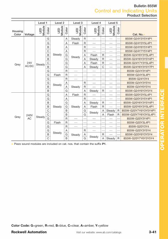
Bulletin 855WControl and Indicating Units
3-41Visit our website: www.ab.com/catalogsRockwell Automation
OP
ER
AT
OR
IN
TE
RFA
CE
Color Code: G=green, R=red, B=blue, C=clear, A=amber, Y=yellow
HousingColor Voltage
Level 1 Level 2 Level 3 Level 4 Level 5
Cat. No.�
LED
Mo
dul
e
Co
lor
LED
Mo
dul
e
Co
lor
LED
Mo
dul
e
Co
lor
LED
Mo
dul
e
Co
lor
LED
Mo
dul
e
Co
lor
Grey 24VAC/DC Steady
G
Steady
A Steady R ⎯ ⎯ ⎯ ⎯ 855W-G24Y3Y5Y4P1
G A Flash R ⎯ ⎯ ⎯ ⎯ 855W-G24Y3Y5L4P1B A
Steady
R ⎯ ⎯ ⎯ ⎯ 855W-G24Y6Y5Y4P1C A R ⎯ ⎯ ⎯ ⎯ 855W-G24Y7Y5Y4P1B G A Flash R ⎯ ⎯ 855W-G24Y6Y3Y5L4P1B G A Steady R ⎯ ⎯ 855W-G24Y6Y3Y5Y4P1C G A Flash R ⎯ ⎯ 855W-G24Y7Y3Y5L4P1B G A Steady C ⎯ ⎯ 855W-G24Y6Y3Y5Y7P1G R ⎯ ⎯ ⎯ ⎯ ⎯ ⎯ 855W-G24Y3Y4P1G Flash R ⎯ ⎯ ⎯ ⎯ ⎯ ⎯ 855W-G24Y3L4P1G
Steady
R ⎯ ⎯ ⎯ ⎯ ⎯ ⎯ 855W-G24Y3Y4G A
SteadyR ⎯ ⎯ ⎯ ⎯ 855W-G24Y3Y5Y4
B A R ⎯ ⎯ ⎯ ⎯ 855W-G24Y6Y5Y4B G A Steady R ⎯ ⎯ 855W-G24Y6Y3Y5Y4
Grey 240VAC Steady
G
Steady
A Flash R ⎯ ⎯ ⎯ ⎯ 855W-G20Y3Y5L4P1G A
Steady
R ⎯ ⎯ ⎯ ⎯ 855W-G20Y3Y5Y4P1B G A Steady R ⎯ ⎯ 855W-G20Y6Y3Y5Y4P1B G A Flash R ⎯ ⎯ 855W-G20Y6Y3Y5L4P1C B G
SteadyA Steady R 855W-G20Y7Y6Y3Y5Y4P1
C B G A Flash R 855W-G20Y7Y6Y3Y5L4P1G R ⎯ ⎯ ⎯ ⎯ ⎯ ⎯ 855W-G20Y3Y4P1G Flash R ⎯ ⎯ ⎯ ⎯ ⎯ ⎯ 855W-G20Y3L4P1G
Steady
R ⎯ ⎯ ⎯ ⎯ ⎯ ⎯ 855W-G20Y3Y4G A
Steady
R ⎯ ⎯ ⎯ ⎯ 855W-G20Y3Y5Y4B G A
SteadyR ⎯ ⎯ 855W-G20Y6Y3Y5Y4
C B G A Steady R 855W-G20Y7Y6Y3Y5Y4
� Piezo sound modules are included on cat. nos. that contain the suffix P1.
Product Selection

Bulletin 2711C, 2706-PGraphic Terminals and Message Displays
3-42 Visit our website: www.ab.com/catalogs Rockwell Automation
OP
ER
AT
OR
INT
ER
FAC
E
Product Line Overview
PanelView™ Component Graphic Terminals�
Bulletin2711C-F2M2711C-K2M
2711C-T3M2711C-K3M
2711C-T6M2711C-T6C 2711C-T10C
Type PanelView C200 PanelView C300 PanelView C600 PanelView C1000Display
Display Type Monochrome:Transflective STN
Monochrome:Transflective FSTN
Monochrome: Transmissive FSTN
Color: Transmissive CSTN
Color: Transmissive TFT
Display Area(WxH)
49 x 14 mm (1.93 x 0.55 in.)
67 x 33 mm(2.64 x 1.30 in.)
115 x 86 mm(4.53 x 3.39 in.)
211 x 158 mm (8.31 x 6.22 in.)
Display Size 2 in. 3 in. 5.7 in. 10.4 in.Resolution 122 x 32 pixels 128 x 64 pixels 320 x 240 pixels 640 x 480 pixels
Operator Input4 function key or
combinationfunction/numeric key
Analogue touch orcombination
function/numeric keyAnalogue touch Analogue touch
Electrical
CommunicationPort
RS232 (9 pin D-Shell),RS422/RS485 (Connector)
RS232(9 pin D-Shell),
RS422/RS485 (Connector)Ethernet
Memory Card USB port USB port USB port or securedigital card
USB port or securedigital card
ProgrammingPort USB device port
Real Time ClockSoftware clockwithout battery
backup
Software clockwithout battery
backupBattery-backed Battery-backed
PowerConsumption
5 W max. (0.21 A at24V DC)
5 W max. (0.21 A at24V DC)
10 W max. (0.42 A at24V DC)
18 W (0.75 A at 24VDC)
PowerRequirements 18…30V DC (24V DC nom.)
EnvironmentalOperatingTemperature 0…50 °C (32…122 °F)
Enclosure IP54, IP65 IP54, IP65 IP54 IP54, IP65Certifications cULus, CE Marked, C-Tick
MechanicalWeight Keypad orKeypad/Touch
0.2 kg0.3 kg
0.2 kg0.3 kg 0.7 kg 1.6 kg
DimensionsOverall (H x W x D)
80 x 116 x 54 mm (3.15 x 4.54 x 2.13
in.)119 x 139 x 55 mm(4.69 x 5.47 x 2.15
in.)
80 x 116 x 57 mm (3.15 x 4.54 x 2.23 in)119 x 139 x 55 mm
(4.69 x 5.47 x 2.15 in)
154 x 209 x 57 mm(6.0 x 8.23 x 2.25 in.)
250 x 308 x 54 mm(9.84 x 12.13 x 2.13 in.)
Dimensions,Cutout (HxW)
65 x 100 mm (2.56 x 3.94 in)100 x 120 mm (3.94 x 4.72 in.)
65 x 100 mm (2.56 x 3.94 in)100 x 120 mm (3.94 x 4.72 in.)
136 x 190 mm (5.35 x 7.48 in.)
232 x 290 mm (9.13 x 11.42 in.)
Product Selection Page 3-44
� For large and/or color display options, visit: http://www.ab.com/eoi/graphicterminals/panelviewcomponent.html
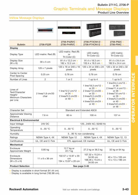
Bulletin 2711C, 2706-PGraphic Terminals and Message Displays
3-43Visit our website: www.ab.com/catalogsRockwell Automation
OP
ER
AT
OR
IN
TE
RFA
CE
InView Message Displays
Bulletin 2706-P22R2706-P42R/C �2706-P44R/C �
2706-P72CN1/2 �2706-P74CN1/2 �
2706-P92C �2706-P94C �
Display
Display Type LED matrix: Red (R)LED matrix: Red (R)
orTri-Color (C)
LED matrix:Tri-Color (C)
LED matrix:Tri-Color (C)
Display Size (W x H) 30 x 5 cm 81.4 x 12.2 cm �
182 x 12.2 cm �91.4 x 18.3 cm �
152.4 x 18.3 cm �91.4 x 24.4 cm182.9 x 24.4 cm
Display Array 120 x 7 pixels 120 x 16 or 240 x 16pixels
120 x 24 or 200 x 24pixels
120 x 32 or 240 x 32pixels
Center to CenterPixel Spacing 0.25 cm 0.76 cm 0.76 cm 0.76 cm
Number of Lines 2 1 or 2 1 up to 4 1 up to 5
Lines ofText/CharacterHeight/Minimum Charactersper Line
2 lines/1.8 cm/20char
1 line/12.2 cm/12 �or 24 �
2 lines/5.3 cm/20 �or 40 �
1 line/18.3 cm/12 �or 20 �
2 lines/7.6 cm/20 �or 33 �
3 lines/5.3 cm/20 �or 33 �
4 lines/3.8 cm/24 �or 40 �
1 line/24.4 cm/13 �or 26 �
2 lines/11.4 cm/13 �or 26 �
3 lines/7.6 cm/13 �or 26 �
4 lines/5.3 cm/20 �or 40 �
5 lines/3.8 cm/24 �or 48 �
Character Set Standard and Extended ASCII
Approximate ViewingDistance 7.6 m 60 m 100 m 137 m
Electrical & Environmental
Input Voltage 24V DC 120...240V AC; 50/60 Hz
OperatingTemperature 0…55 °C 0…50 °C 0…50 °C 0…50 °C
Humidity 5…95 % non condensing
Ratings NEMA Type 4, 4X NEMA Type 12 NEMA Type 4, 4X NEMA Type 12, 13
Certifications UL, CE and C-Tick ETL approved; CE marked UL, CE and C-Tick
Mechanical
EnclosureApproximate Weight 0.85 kg 12.7 kg or
22.7 kg 27.2 kg or 36.3 kg 32 kg or 64 kg
EnclosureDimensions(W x D x H)
11 x 6 x 36 cm102.57 x 13.97 x 20
cm194 x 13.97 x 20 cm
107.32 x 15.24 x34.93 cm
168.28 x 15.24 x34.93 cm
40 x 13 x 105 cm14 x 13 x 196 cm
Product Selection See page 3-45
� Display is available in short format (91.44 cm).�Display is available in long format (182.88 cm).
Product Line Overview

Bulletin 2711CGraphic Terminals and Message Displays
3-44 Visit our website: www.ab.com/catalogs Rockwell Automation
OP
ER
AT
OR
INT
ER
FAC
E
Product Selection
PanelView Component C200…C1000 Terminals� Optimized for communication with MicroLogix or SLC 500
controllers: DF1, DH-485, Ethernet to MicroLogix or SLC500 controller, and multi-vendor communications
� Display information in several languages includingRussian, Greek, Chinese, Japanese and Korean
� Alert operators with alarm messages that include variables� Upload and download groups of data or parameter
settings with recipe feature� Secure information on screens with user name and
password protection
Software� Design software is on the PanelView Component operator
interface so there's no need to install software on the PC� PC-based software is also availableCommunication
PanelView Component Terminals
PanelView Component terminals offer standard communication options - RS232, RS485, as well asmany vendor communication options including Modbus and Modbus/TCP. The PanelViewComponent 6-inch and 10-inch terminals have Ethernet as additional communication option.
Terminals Description Cat. No.
C200
PanelView C200, 2-inch monochrome STN display with four function keys,serial communications, 24V DC power 2711C-F2M
PanelView C200, 2-inch monochrome STN display with ten function keys andnumeric keypad, serial communications, 24V DC power 2711C-K2M
C300
PanelView C300, 3-inch monochrome FSTN display with touch screen, serialcommunications, 24V DC power 2711C-T3M
PanelView C300, 3-inch monochrome FSTN display with ten function keysand numeric keypad, serial communications, 24V DC power 2711C-K3M
C600
PanelView C600, 6-inch monochrome FSTN display with touch screen, serialand Ethernet communication, 24V DC power 2711C-T6M
PanelView C600, 6-inch color CSTN display with touch screen, serial andEthernet communication, 24V DC power 2711C-T6C
C1000 PanelView C1000, 10-inch color TFT display with touch screen, serial andEthernet communication, 24V DC power 2711C-T10C
Accessories for PanelView Component C200 - C1000
Description Cat. No.
USB host to USB device programming cable for PanelView Component terminals,2 m (6.5 ft) 2711C-CBL-UU02
SLC 5/03, SLC 5/04, and SLC 5/05 RS-232 programmer cable 1747-CP3
RS-232 operating/programming cable, 8-Pin Mini DIN to 9-Pin D Shell (MicroLogix), 2 m (6.5 ft) 1761-CBL-PM02
Ethernet CAT5 crossover industrial cable, 4.3 m (14 ft) 2711P-CBL-EX04
USB secure digital 128 MB memory card for PanelView component devices 2711C-RCSD
Protective antiglare overlay for PanelView C200 function key and C300 touch-screenterminals (Quantity 3) 2711C-RG2F
Protective antiglare overlay for PanelView C200 and C300 keypad terminals (Quantity 3) 2711C-RG2K
Protective antiglare overlay for PanelView C600 touch-screen terminals (Quantity 3) 2711C-RG6T
Protective antiglare overlay for PanelView C1000 terminals (Quantity 3) 2711C-RG10T
RS422/485 connector with resistor (Quantity 10) 2711C-RJ422
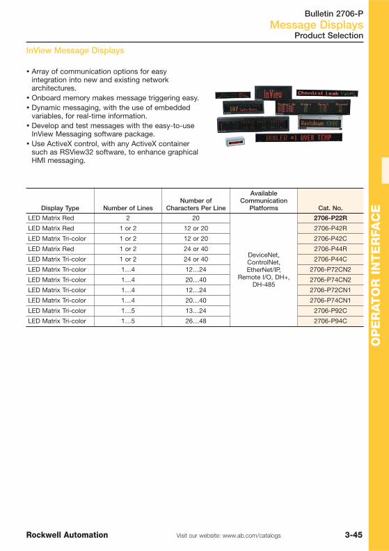
Bulletin 2706-PMessage Displays
3-45Visit our website: www.ab.com/catalogsRockwell Automation
OP
ER
AT
OR
IN
TE
RFA
CE
InView Message Displays
Product Selection
� Array of communication options for easyintegration into new and existing networkarchitectures.
� Onboard memory makes message triggering easy.� Dynamic messaging, with the use of embedded
variables, for real-time information.� Develop and test messages with the easy-to-use
InView Messaging software package.� Use ActiveX control, with any ActiveX container
such as RSView32 software, to enhance graphicalHMI messaging.
Display Type Number of LinesNumber of
Characters Per Line
AvailableCommunication
Platforms Cat. No.
LED Matrix Red 2 20
DeviceNet,ControlNet,EtherNet/IP,
Remote I/O, DH+,DH-485
2706-P22R
LED Matrix Red 1 or 2 12 or 20 2706-P42R
LED Matrix Tri-color 1 or 2 12 or 20 2706-P42C
LED Matrix Red 1 or 2 24 or 40 2706-P44R
LED Matrix Tri-color 1 or 2 24 or 40 2706-P44C
LED Matrix Tri-color 1…4 12…24 2706-P72CN2
LED Matrix Tri-color 1…4 20…40 2706-P74CN2
LED Matrix Tri-color 1…4 12…24 2706-P72CN1
LED Matrix Tri-color 1…4 20…40 2706-P74CN1
LED Matrix Tri-color 1…5 13…24 2706-P92C
LED Matrix Tri-color 1…5 26…48 2706-P94C

Bulletin 2706-PMessage Displays
3-46 Visit our website: www.ab.com/catalogs Rockwell Automation
OP
ER
AT
OR
INT
ER
FAC
E
Accessories for InView Message Displays
Accessories
InView Software
InView Communication Modules
Description Cat. No.
InView Messaging Software 2706-PSW1
Description For Use With Mounting Cat. No.
InView DeviceNet
P22R, 24V DC DIN Rail 2706-PDNETP
P4x Back of Display 2706-PDNETM
P7x and P9x Inside Display 2706-PDNETK
InView ControlNet
P22R, 24V DC DIN Rail 2706-PCNETP
P4x Back of Display 2706-PCNETM
P7x and P9x Inside Display 2706-PCNETK
InView EtherNet/IP
P22R, 24V DC DIN Rail 2706-PENETP
P4x Back of Display 2706-PENETM
P7x and P9x Inside Display 2706-PENETK
InView Remote I/O
P22R, 24V DC DIN Rail 2706-PRIOP
P4x Back of Display 2706-PRIOM
P7x and P9x Inside Display 2706-PRIOK
InView DH+
P22R, 24V DC DIN Rail 2706-PDHPP
P4x Back of Display 2706-PDHPM
P7x and P9x Inside Display 2706-PDHPK
InView DH-485
P22R, 24V DC DIN Rail 2706-PDH485P
P4x Back of Display 2706-PDH485M
P7x and P9x Inside Display 2706-PDH485K
InView Ethernet TCP/IP 2706-PENET1
InView Program/Download Cable 2706-PCABLE1

Visit our website: www.ab.com/catalogsRockwell Automation
TABLE OF CONTENTS
4-1
Connectivity
Terminal Blocks 4-2
Wiring Systems 4-11
ArmorConnect Power Media 4-12
DeviceNetTM Media 4-14
Ethernet Media 4-26
Distributed I/O 4-30
Connection Systems 4-35

Bulletin 1492-J, 1492-L, 1492-KTerminal Blocks
4-2 Visit our website: www.ab.com/catalogs Rockwell Automation
CO
NN
EC
TIV
ITY
Terminal Blocks Selection
Product Line Overview
Bulletin 1492-J 1492-L
Type Screw Type Terminal Blocks Spring-Clamp Terminal Blocks
Features
� Mini terminal blocks for 15 mm DINrail
� Terminals for 35 mm DIN rail� Two level terminal blocks
— with diode— in forward bias or in reverse bias— with selectable resistor— with MOV
� Two pole thermocouple blocks
� Terminals for 35 mm DIN rail� Single circuit terminal blocks
available in 8 colours� Component blocks
— with a diode — in forward bias or in reverse bias— Resistor selectable— with MOV
Approvals UR, CSA, IEC
Accessories
Test Plugs/Test Plug Adapters, EndAnchors, End Barriers, PartitionPlates, Side Jumpers, Centre JumperBars, Centre Jumper Covers, NeutralConnecting Blocks, Commoning BusBars, Warning Plates, Group MarkingCarriers
End Retainers/Group MarkingCarriers, Terminal Covers, CentreJumpers, Centre Jumper Links,QuickClamp Insulation Stops, MarkerCard Adapters
Product Selection See page 4-3 See page 4-6
Power Distribution Block Selection
Bulletin 1492-PDE
Features� Can be mechanically connected for multiple pole requirements� Panel-mounting� IP2X Finger-safe from front
Current Range 175…510 A
Number of Poles 1-pole
Distribution Block Wiring 1, 2, 4, and 8 wires per pole
Max. Voltage Ratings 600V AC/DC
Insulation Material Max. Temp. 125 °C (257 °F)
Power Block Material Aluminum or Copper
Wire Size 400 kcmil... #16 AWG per phase Cu
Certifications CE Compliant, CSA Certified and UL Recognized
Product Selection Page 4-10

Bulletin 1492-JTerminal Blocks
4-3Visit our website: www.ab.com/catalogsRockwell Automation
CO
NN
EC
TIV
ITY
Type
6 mm2 10 mm2
PQ Cat. No. PQ Cat. No.
Terminal Block Grey 100 1492-J6 50 1492-J10
Colour 100 1492-J6-� 50 1492-J10-�
Accessories
Marking Systems:Marker card 5 1492-M7X12
(108/card) 5 1492-M7X12(108/card)
End barrier Grey 50 1492-EBJ3 50 1492-EBJ3
Screw centre jumper (10 pole) 20 1492-CJJ8-10 20 1492-CJJ10-10
Screw centre jumper (2 pole) 50 1492-CJJ8-2 50 1492-CJJ10-2
Partition Plates 20 1492-EBJ16 20 1492-EBJ16
Feed-Through Terminal Blocks 2.5…4 mm2
Screw Type Terminal Blocks
Product Selection
Type
2.5 mm2 4 mm2
PQ Cat. No. PQ Cat. No.
Terminal Block Grey 100 1492-J3 100 1492-J4
Colour 100 1492-J3-� 100 1492-J4-�
Accessories
Marking Systems:Marker card 5 1492-M5X12
(144/card) 5 1492-M6X12(120/card)
End barrier Grey 50 1492-EBJ3 50 1492-EBJ3
Screw centre jumper (10 pole) 20 1492-CJJ5-10 20 1492-CJJ6-10
Screw centre jumper (2 pole) 50 1492-CJJ5-2 50 1492-CJJ6-2
Partition Plates 20 1492-EBJ16 20 1492-EBJ16
Feed-Through Terminal Blocks 6…10 mm2
Feed-Through Terminal Blocks 16…35 mm2
Type
16 mm2 35 mm2
PQ Cat. No. PQ Cat. No.
Terminal Block Grey 50 1492-J16 40 1492-J35
Colour 50 1492-J16-� 40 1492-J35-�
Accessories
Marking Systems:Marker card 5 1492-M7X12
(108/card) 5 1492-M7X12(108/card)
End barrier Grey 20 1492-EBJ16 20 1492-EBJ16
Screw centre jumper (10 pole) 10 1492-CJJ12-10 10 1492-CJJ16-10
Screw centre jumper (2 pole) 20 1492-CJJ12-2 20 1492-CJJ16-2
Partition Plates 20 1492-PPJD3 20 1492-PPJD3
� For colored blocks, add suffix RE = Red, B = Blue, BL = Black, G = Green, Y = Yellow, OR = Orange,BR = Brown, W = White to the end of the catalog number.
PQ = Package Quantity

Bulletin 1492-JTerminal Blocks
4-4 Visit our website: www.ab.com/catalogs Rockwell Automation
CO
NN
EC
TIV
ITY
Feed-Through Terminal Blocks 50…70 mm2
Screw Type Terminal Blocks
Type
50 mm2 70 mm2
PQ Cat. No. PQ Cat. No.
Terminal Block Grey 10 1492-J50 10 1492-J70
Blue 10 1492-J50-B 10 1492-J70-B
Accessories
Marking Systems:Marker card 5 1492-M7X12
(108/card) 5 1492-M7X12(108/card)
End barrier — Not Required — Not Required
End Anchor
DIN Rail — Heavy Duty 50 1492-EAHJ35 50 1492-EAHJ35
Jumpers
Screw centre jumper (4 pole) 10 1492-CJJ18-4 5 1492-CJJ20-4
Screw centre jumper (3 pole) 10 1492-CJJ18-3 5 1492-CJJ20-3
Screw centre jumper (2 pole) 10 1492-CJJ18-2 5 1492-CJJ20-2
PQ = Package Quantity
Product Selection
Feed-Through Terminal Blocks 120…240 mm2
Type
120 mm2 240 mm2
PQ Cat. No. PQ Cat. No.
Terminal Block Grey 5 1492-J120 — —
Beige — — 2 1492-J240
Accessories
Marking Systems:Marker card 5 1492-M8X12
(84/card) 5 1492-M8X12(84/card)
End barrier — Not Required — Not Required
End Anchor
DIN Rail — Heavy Duty 50 1492-EAHJ35 50 1492-EAHJ35
Jumpers
Screw centre jumper (4 pole) 5 1492-CJJ27-4 — —
Screw centre jumper (3 pole) 5 1492-CJJ27-3 — —
Screw centre jumper (2 pole) 5 1492-CJJ27-2 — —
Side jumper (3 pole) — — 5 1492-SJ36-3
Side jumper (2 pole) — — 5 1492-SJ36-2
PQ = Package Quantity
See Publication A116 for complete product information.

Bulletin 1492-JTerminal Blocks
4-5Visit our website: www.ab.com/catalogsRockwell Automation
CO
NN
EC
TIV
ITY
Product Selection
Type
4 mm2 6 mm2 10 mm2
PQ Cat. No. PQ Cat. No. PQ Cat. No.
Terminal Blocks Green/Yellow 100 1492-JG4 50 1492-JG6 50 1492-JG10
Accessories
Marking Systems:Marker card 5 1492-M6X12
(120/card) 5 1492-M7X12(108/card) 5 1492-M7X12
(108/card)
End Anchors
DIN Rail - Normal Duty 100 1492-EAJ35 100 1492-EAJ35 100 1492-EAJ35
DIN Rail - Heavy Duty 50 1492-EAHJ35 50 1492-EAHJ35 50 1492-EAHJ35
Screw Type Terminal Blocks
Type
16 mm2 35 mm2
PQ Cat. No. PQ Cat. No.
Terminal Blocks Green/Yellow 50 1492-JG16 25 1492-JG35
Accessories
Marking Systems:Marker card 5 1492-M7X12
(108/card) 5 1492-M7X12(108/card)
End Anchors
DIN Rail - Heavy Duty 50 1492-EAHJ35 50 1492-EAHJ35
Feed-Through Ground Blocks 4…10 mm2
Feed-Through Ground Blocks 16…35 mm2
Multi-Circuit Feed-Through Blocks
1492-JG… 1492-JD… 1492-WFB4
Type
2.5 mm2 4 mm2
PQ Cat. No. PQ Cat. No.
Terminal Blocks Grey 100 1492-JD3 100 1492-JD4
Colour 100 1492-JD3-� 100 1492-JD4-�
Accessories
End Barrier Grey 20 1492-EBJD3 20 1492-EBJD4
Screw center jumper (10-pole) 20 1492-CJJ5-10 20 1492-CJLJ6-10
Screw center jumper (2-pole) 50 1492-CJJ5-2 60 1492-CJLJ6-2
Partition Plate 20 1492-PPJD3 20 1492-PPJD3
Marking Systems:Snap-in Marker Cards 5 1492-MR5X8
(120/card) 5 1492-MR6X8(120/card)
� For colored blocks, add suffix RE = Red, B = Blue, BL = Black, G = Green, Y = Yellow, OR = Orange,BR = Brown, W = White to the end of the catalog number.
Fuse Blocks
Type 4 mm2
Terminal Block PQ Cat. No.
Black-No Indication 50 1492-WFB4
PQ = Package Quantity

Bulletin 1492-LTerminal Blocks
4-6 Visit our website: www.ab.com/catalogs Rockwell Automation
CO
NN
EC
TIV
ITY
Type
10 mm2 16 mm2
PQ Cat. No. PQ Cat. No.
Terminal Blocks Grey 25 1492-L10 25 1492-L16
Colour 25 1492-L10-� 25 1492-L16-�
Accessories
End barrier Grey 20 1492-EBL10 20 1492-EBL16
Centre jumper with Plug (2 pole) 25 1492-CJL10-2 5 1492-M7X12(108/card)
Marking Systems:Marker card 5 1492-M6X12
(120/card) — —
� For colored blocks, add suffix RE = Red, B = Blue, BL = Black, G = Green, Y = Yellow, OR = Orange,BR = Brown, W = White to the end of the catalog number.
Spring-Clamp Terminal Blocks
Product Selection
Type
2.5 mm2 4 mm2 6 mm2
PQ Cat. No. PQ Cat. No. PQ Cat. No.
Terminal Blocks Grey 100 1492-L3 50 1492-L4 50 1492-L6
Colour 100 1492-L3-� 50 1492-L4-� 50 1492-L6-�
Accessories
End barrier Grey 50 1492-EBL3 50 1492-EBL3 50 1492-EBL6
Centre jumper with Plug (10 pole) 20 1492-CJK5-10 20 1492-CJK6-10 60 1492-CJL8-2
Centre jumper with Plug (2 pole) 60 1492-CJK5-2 60 1492-CJK6-2 5 1492-M6X12(120/card)
Reducing Sleeves 0.25…0.5 mm2100 1492-PSL3-5 100 1492-PSL4-5
— —
(#22…#20 AWG) Grey — —
Marking Systems:Marker card 5 1492-M5X10
(144/card) 5 1492-M6X10(120/card) — —
Feed-Through Terminal Blocks 2.5…6 mm2
Feed-Through Terminal Blocks 10…16 mm2
Type
2.5 mm2 4 mm2 6 mm2
PQ Cat. No. PQ Cat. No. PQ Cat. No.
Terminal Blocks Green/Yellow 100 1492-LG3 50 1492-LG4 50 1492-LG6
Accessories
End barrier Yellow 50 1492-EBL3-Y 50 1492-EBL4-Y 50 1492-EBL6-Y
Reducing Sleeves 0.25…0.5 mm2100 1492-PSL3-5 100 1492-PSL4-5
5 1492-M6X12(120/card)
(#22…#20 AWG) Grey — —
Marking Systems:Marker card 5 1492-M5X10
(144/card) 5 1492-M5X10(144/card) — —
PQ = Package Quantity
For Feed-Through Ground Blocks 10 mm2 and 16 mm2. see Publication A116.
Feed-Through Ground Blocks 2.5…6 mm2

Bulletin 1492-LTerminal Blocks
4-7Visit our website: www.ab.com/catalogsRockwell Automation
CO
NN
EC
TIV
ITY
Product Selection
Type
2.5 mm2 2.5 mm2
PQ Cat. No. PQ Cat. No.
Terminal Blocks Grey 100 1492-L3T 100 1492-L3Q
Colour 100 1492-L3T-� 100 1492-L3Q-�
Accessories
Marking Systems:Snap-in Marker Cards 5 1492-M5X10
(144/card) 5 1492-M5X10(144/card)
End Barriers Grey 50 1492-EBL3T 50 1492-EBL3Q
End Anchors
DIN Rail — Normal Duty 100 1492-EAJ35 100 1492-EAJ35
DIN Rail — Heavy Duty 50 1492-EAHJ35 50 1492-EAHJ35
Jumpers
Plug-in Center Jumper — 4-Pole 60 1492-CJK5-4 60 1492-CJK5-4
Plug-in Center Jumper — 3-Pole 60 1492-CJK5-3 60 1492-CJK5-3
Plug-in Center Jumper — 2-Pole 60 1492-CJK5-2 60 1492-CJK5-2
Type
2.5 mm2
PQ Cat. No.
Terminal Blocks Green/Yellow 50 1492-LG3T
Accessories
Marking Systems:Snap-In Marker Cards 5 1492-M5X10
(144/card)
End Barrier Yellow 50 1492-EBL3T-Y
End Anchors
DIN Rail — Normal Duty 100 1492-EAJ35
DIN Rail — Heavy Duty 50 1492-EAHJ35
Multi-Circuit Feed-Through Blocks
Type
2.5 mm2
PQ Cat. No.
Terminal Blocks Grey 25 1492-LD3
Colour 25 1492-LD3-�
Accessories
Marking Systems:Marker Card 5 1492-M5X10
(144/card)
End Barrier 20 1492-EBLD3
Plug-in Centre Jumper (10-Pole) 20 1492-CJK5-10
Plug-in Centre Jumper (2-Pole) 60 1492-CJK5-2
� For coloured blocks, add suffix RE = Red, B = Blue, BL = Black, G = Green, Y = Yellow, OR = Orange,BR = Brown, W = White to the end of the catalogue number.
PQ = Package Quantity
Multiple Contact Point Feed-Through Blocks
Grounding Block with 2 points on one side

Bulletin 1492-LTerminal Blocks
4-8 Visit our website: www.ab.com/catalogs Rockwell Automation
CO
NN
EC
TIV
ITY
See Publication 1492-SG008… for complete product information.
Marker cards for 1492-J, 1492-L
For Type Labels per Card Color PQ Cat. No.
1492-J, -L 144 White
5
1492-M5X10
1492-M5X12
1492-J, -L 120 White1492-M6X10
1492-M6X12
1492-J, -L 108 White 1492-M7X12
PQ = Package Quantity
Single Circuit Fuse Terminal Block 4 mm2
Spring-Clamp Terminal Blocks
Type
4 mm2
PQ Cat. No.
Blown Fuse Indication Black with 10…57V LED 25 1492-RFB424
Black with 85…264V Glow Lamp 25 1492-RFB4250
Accessories
Spring clamp-End Anchor 20 1492-ERL35
Marking Systems:Marker card 5 1492-MS6X9
(80/card)
Product Selection
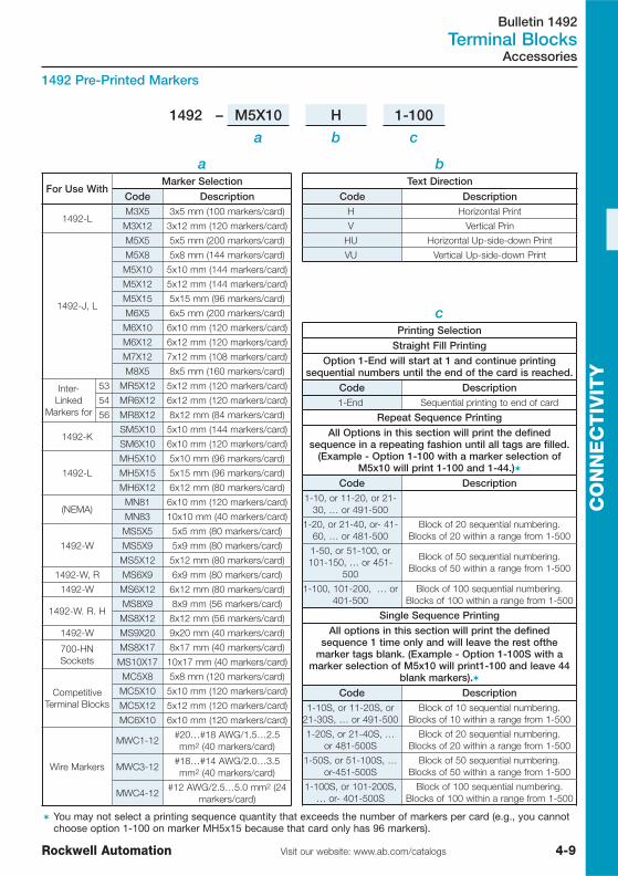
Bulletin 1492Terminal Blocks
4-9Visit our website: www.ab.com/catalogsRockwell Automation
CO
NN
EC
TIV
ITY
Accessories
� You may not select a printing sequence quantity that exceeds the number of markers per card (e.g., you cannotchoose option 1-100 on marker MH5x15 because that card only has 96 markers).
1492 – M5X10 H 1-100
a b c
bText Direction
Code DescriptionH Horizontal Print
V Vertical Prin
HU Horizontal Up-side-down Print
VU Vertical Up-side-down Print
a
For Use WithMarker Selection
Code Description
1492-LM3X5 3x5 mm (100 markers/card)
M3X12 3x12 mm (120 markers/card)
1492-J, L
M5X5 5x5 mm (200 markers/card)
M5X8 5x8 mm (144 markers/card)
M5X10 5x10 mm (144 markers/card)
M5X12 5x12 mm (144 markers/card)
M5X15 5x15 mm (96 markers/card)
M6X5 6x5 mm (200 markers/card)
M6X10 6x10 mm (120 markers/card)
M6X12 6x12 mm (120 markers/card)
M7X12 7x12 mm (108 markers/card)
M8X5 8x5 mm (160 markers/card)
Inter-Linked
Markers for
53 MR5X12 5x12 mm (120 markers/card)
54 MR6X12 6x12 mm (120 markers/card)
56 MR8X12 8x12 mm (84 markers/card)
1492-KSM5X10 5x10 mm (144 markers/card)
SM6X10 6x10 mm (120 markers/card)
1492-L
MH5X10 5x10 mm (96 markers/card)
MH5X15 5x15 mm (96 markers/card)
MH6X12 6x12 mm (80 markers/card)
(NEMA)MN81 6x10 mm (120 markers/card)
MN83 10x10 mm (40 markers/card)
1492-W
MS5X5 5x5 mm (80 markers/card)
MS5X9 5x9 mm (80 markers/card)
MS5X12 5x12 mm (80 markers/card)
1492-W, R MS6X9 6x9 mm (80 markers/card)
1492-W MS6X12 6x12 mm (80 markers/card)
1492-W. R. HMS8X9 8x9 mm (56 markers/card)
MS8X12 8x12 mm (56 markers/card)
1492-W MS9X20 9x20 mm (40 markers/card)
700-HNSockets
MS8X17 8x17 mm (40 markers/card)
MS10X17 10x17 mm (40 markers/card)
CompetitiveTerminal Blocks
MC5X8 5x8 mm (120 markers/card)
MC5X10 5x10 mm (120 markers/card)
MC5X12 5x12 mm (120 markers/card)
MC6X10 6x10 mm (120 markers/card)
Wire Markers
MWC1-12#20…#18 AWG/1.5…2.5mm2 (40 markers/card)
MWC3-12#18…#14 AWG/2.0…3.5mm2 (40 markers/card)
MWC4-12#12 AWG/2.5…5.0 mm2 (24
markers/card)
cPrinting Selection
Straight Fill Printing
Option 1-End will start at 1 and continue printingsequential numbers until the end of the card is reached.
Code Description1-End Sequential printing to end of card
Repeat Sequence Printing
All Options in this section will print the definedsequence in a repeating fashion until all tags are filled.
(Example - Option 1-100 with a marker selection ofM5x10 will print 1-100 and 1-44.)�
Code Description1-10, or 11-20, or 21-
30, … or 491-500
1-20, or 21-40, or- 41-60, … or 481-500
Block of 20 sequential numbering.Blocks of 20 within a range from 1-500
1-50, or 51-100, or101-150, … or 451-
500
Block of 50 sequential numbering.Blocks of 50 within a range from 1-500
1-100, 101-200, … or401-500
Block of 100 sequential numbering.Blocks of 100 within a range from 1-500
Single Sequence Printing
All options in this section will print the definedsequence 1 time only and will leave the rest ofthe
marker tags blank. (Example - Option 1-100S with amarker selection of M5x10 will print1-100 and leave 44
blank markers).�
Code Description1-10S, or 11-20S, or
21-30S, … or 491-500Block of 10 sequential numbering.
Blocks of 10 within a range from 1-500
1-20S, or 21-40S, …or 481-500S
Block of 20 sequential numbering.Blocks of 20 within a range from 1-500
1-50S, or 51-100S, …or-451-500S
Block of 50 sequential numbering.Blocks of 50 within a range from 1-500
1-100S, or 101-200S,… or- 401-500S
Block of 100 sequential numbering.Blocks of 100 within a range from 1-500
1492 Pre-Printed Markers

Bulletin 1492Terminal Blocks
4-10 Visit our website: www.ab.com/catalogs Rockwell Automation
CO
NN
EC
TIV
ITY
Accessories
1492-PLTKIT
IEC Marking System
Advantages� Plot partial marker card� Load up to 5 cards at a time (mix and match)� Easy to use AB-Plot software� Character customization� Supported by Allen-Bradley and its extensive
network of distributors� Can print markers for Terminal Blocks,
contactors, relays, and more
Description Cat. No.
Plotter KitIncludes Series E Plotter, 1492-PLOTPEN25 ink pen, 1492-PLOTPLT plate,communication cables, user manuals, ABPLOT software, and poweradaptor.
1492-PLTKIT
Product SelectionBulletin 1492-PDE — Enclosed Power Blocks
� IP2X from the front� Single-pole blocks w/ aluminum or copper connectors� May be mechanically connected for multiple pole requirements� Panel-mounting
Amps(Cu
Wire)75 °C
No.of
Poles
Line Load
Cat. No.�
ConnectorConfigura-
tion Wire Range�Openingsper Pole
ConnectorConfigura-
tionWire
Range�Openingsper Pole
175 1 2/0…#14 AWG(70…2.5 mm2) 1
2/0…#14AWG
(70…2.5mm2)
1
1492-PDE1111
1492-PDE1C111
175 1 2/0…#14 AWG(70…2.5 mm2) 1
#2…14AWG
(35…2.5mm2)
4
1492-PDE1141
1492-PDE1C141
510 1250 kcmil…#6AWG (120…16
mm2)2
250kcmil…#6
AWG(120…16
mm2)
2
1492-PDE1225
1492-PDE1C225
335 1
400 kcmil…#6AWG (185…16
mm2)2/0…#14 AWG(70…2.5 mm2)
1
#2…16AWG
(35…1.5mm2)
8
1492-PDE1183
1492-PDE1C183
� Allen-Bradley power distribution blocks are rated for use with flexible wire. Please see www.ab.com for moreinformation.
� The C in the catalog number designates copper terminals. Catalog numbers without the C, have aluminumconnectors

Bulletin 1492Wiring Systems
4-11Visit our website: www.ab.com/catalogsRockwell Automation
CO
NN
EC
TIV
ITY
Product Line Overview
Wiring System Selection Bulletin 1492
For complete product information, please see catalogue A116 or our on-line selection tools atwww.ab.com
For Bulletin 1762 / MicroLogix 1200 1764 / MicroLogix 1500 1769 / Compact I/O
Features
� Reduced wiring time� Reduced wiring errors� Faster troubleshooting and easier maintenance� Reduced wire preparation and routing� Increased DIN Rail density� Fewer parts, less inventory and lower carrying cost� Design flexibility
Description
Connecting to Allen-Bradley PLC I/O modules is convenient with Allen-Bradley 1492 Wiring System Interface Modules and Cables. Unlike terminalblocks, they connect through pre-wired cables to digital and analog I/O forCompact I/O for CompactLogix and MicroLogix. The interface modules aremounted onto a standard DIN #3 Rail. Pre-printed adhesive label cardscontaining field-wiring information are included for each interface module andI/O module combination. Wiring systems are available for many digital andanalog I/O modules.

Bulletin 280
ArmorConnectTM Power Media
4-12 Visit our website: www.ab.com/catalogs Rockwell Automation
CO
NN
EC
TIV
ITY
Three-Phase Power Media for ArmorStart
Product Line Overview
Three-PhasePower
Trunk Cable
Three-PhasePower
Drop Cable
Three-PhasePower
Tees andReducers
Three-PhasePower
Receptacles
Three-PhasePower
Accessories
Description
� Cordset - cablewith integralfemale or maleconnector onone end
� PatchCord -cable withintegral femaleor maleconnector oneach end
� Cordset - cablewith integralfemale or maleconnector onone end
� PatchCord -cable withintegral femaleor maleconnector oneach end
� Tee - connectsto a single dropline to trunkwith quickchangeconnectors
� Reducing Tee -connects to asingle drop line(mini) to trunk(cuick change)connector
� Reducer -connects fromquick changemale connectorto mini femaleconnector
� Femalereceptacles area panel mountconnector withflying leads
� Malereceptacles area motor juctionbox mountedconnector withflying leads
� Sealing Capsoffered inversions tointerface withfemale or maleconnectors
� Locking Clipsclamshelldesign clipsover threepower phaseconnector tolimit customeraccess
Features
� Rated for motorbranch circuits
� Straight or rightangleconnectors
� 4-pin connectortype
� Cable rating:TC-ER/STOOW
� Multiplestandardlengths
� Rated for motorbranch circuits
� Straight or rightangleconnectors
� 4-pin connectortype
� Cable rating:TC-ER/STOOW
� Multiplestandardlengths
� Rated for motorbranch circuits
� Trunk Tee,Reducing Teeand Reducer
� 4-pin connectortype
� Rated for motorbranch circuits
� Male andfemaleconfigurations
� 4-pin connectortype
� 1/2 in. NPT� Available in 1
meter length
� Sealing Caps -available inquick changeand mini styles
� Locking Clipsare design forthe quickchange andmini styleconnectors
Rated Voltage 600V 600V 600V 600V ⎯
ConnectorBodyDimensions
Straight:88.9 x 38.6 mmRight Angle:75.5 x 74 mm
Straight:56. x 25.4 mmRight Angle:44.9 x 40.4 mm
Trunk Tee:108 x 73.6 mmReducing Tee:108 x 65.5 mmReducer:112.5 x 38.1 mm
M22 Female:33.45 x 25.45 mmM22 Male:28.04 x 25.45 mmM35 Female:71.12 x 38.10 mmM35 Male:63.50 x 38.10 mm
⎯
For complete product information, please see catalogue A116 or our on-line selection tools atwww.ab.com
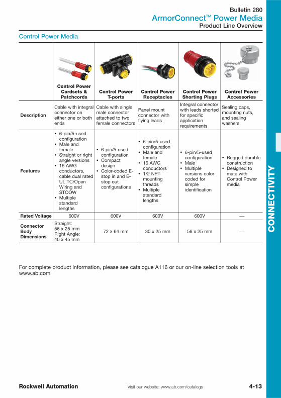
Bulletin 280
ArmorConnectTM Power Media
4-13Visit our website: www.ab.com/catalogsRockwell Automation
CO
NN
EC
TIV
ITY
Product Line Overview
Control Power Media
Control Power Cordsets &Patchcords
Control Power T-ports
Control Power Receptacles
Control Power Shorting Plugs
Control Power Accessories
Description
Cable with integralconnector oneither one or bothends
Cable with singlemale connectorattached to twofemale connectors
Panel mountconnector withflying leads
Integral connectorwith leads shortedfor specificapplicationrequirements
Sealing caps,mounting nuts,and sealingwashers
Features
� 6-pin/5-usedconfiguration
� Male andfemale
� Straight or rightangle versions
� 16 AWGconductors,cable dual ratedUL TC/OpenWiring andSTOOW
� Multiplestandardlengths
� 6-pin/5-usedconfiguration
� Compactdesign
� Color-coded E-stop in and E-stop outconfigurations
� 6-pin/5-usedconfiguration
� Male andfemale
� 16 AWGconductors
� 1/2 NPTmountingthreads
� Multiplestandardlengths
� 6-pin/5-usedconfiguration
� Male� Multiple
versions colorcoded forsimpleidentification
� Rugged durableconstruction
� Designed tomate withControl Powermedia
Rated Voltage 600V 600V 600V 600V ⎯
ConnectorBodyDimensions
Straight:56 x 25 mmRight Angle:40 x 45 mm
72 x 64 mm 30 x 25 mm 56 x 25 mm ⎯
For complete product information, please see catalogue A116 or our on-line selection tools atwww.ab.com

Bulletin 1485, 1585
DeviceNetTM Media
4-14 Visit our website: www.ab.com/catalogs Rockwell Automation
CO
NN
EC
TIV
ITY
DeviceNetTM Media
Product Line Overview
DeviceNetTM Flat Media System — KwikLinkTM General Purpose Typical Configuration
12
16
9
8
34
5
6
7
11
10
13
4
12
14
15
1 KwikLink General Purpose Flat Trunk Cable2 KwikLink General Purpose Connector3 Micro Terminator4 Flat Cable End Cap5 KwikLink Drop Cable
6 Conduit Adaptor
7 Mounting Clamp8 ArmorBlock MaXum
9 Standard Cordsets10 DeviceNet Photoelectric11 DeviceNet Inductive
12 DeviceNet Limit Switch13 DeviceNet Encoder
14 Standard Photoelectric15 Standard Proximity16 Standard Limit Switch
Open Style Device
DeviceNet Power Supply
PLC
Enclosure
See Publication M115-CA001… for complete product information
Bulletin 1485
TypeDeviceNetTM Flat Media
System—KwikLinkTM
General Purpose
DeviceNetTM Flat MediaSystem—KwikLinkTM
Heavy Duty
DeviceNetTM RoundMedia
Thick Trunk System
DeviceNetTM RoundMedia
Thin Trunk System
ProductSelection this page Page 4-16 Page 4-19 Page 4-20

Bulletin 1485
DeviceNetTM Media
4-15Visit our website: www.ab.com/catalogsRockwell Automation
CO
NN
EC
TIV
ITY
Description Spool Rating Used Color Cat. No.
DeviceNet KwikLinkCL2 TrunkCable
75 m 24VDC, 4 A(Class
2)
DeviceNet
Trunk
Grey(PVC)
1485C-P1K75
200 m 1485C-P1K200
420 m 1485C-P1K420
Note: KwikLink General Purpose Flat Cables are not recommended for use with original Heavy Duty KwikLinkconnectors.
(Only for use with KwikLink General Purpose connector 1485P-K1E4-R5)
See Publication M115-CA001… for complete product information
Description Cat. No.
KwikLink General PurposeConnector Micro Style 1485P-K1E4-R5
In order to support all of the options associated with the flexibility of KwikLink, Allen-Bradley offersan array of accessories including cable mounts, conduit adaptors, flat cable end caps and threadedplugs for sealing unused micro connectors.
Description Cat. No.
Standalone Flat Cable End Cap 1485A-KCAP
Micro Terminator, Male 1485A-T1D5
Flat Cable Conduit Adapter 1485A-CAD
Flat Cable Mounting Clamp 1485A-FCM
KwikLinkTM Accessories
KwikLink General Purpose Flat Cable Trunk
KwikLink General Purpose Connector
DeviceNetTM Flat Media System — KwikLinkTM General Purpose, continued
Accessories

Bulletin 1485
DeviceNetTM Media
4-16 Visit our website: www.ab.com/catalogs Rockwell Automation
CO
NN
EC
TIV
ITY
Product Line Overview
DeviceNetTM Flat Media System — KwikLinkTM Heavy DutyTypical Configuration
1
2
3
4 5 6
11
8
7
10
12
13
13
1417
17
18
19
20
21
22
2324
25
15
17
5
9
4
99
9
9
17
17
20
1 Flat Trunk Cable2 Flat Auxiliary Power Cable
3 Splice Kit4 Terminator
5 Connector IDC6 Open Style IDC7 Class I Drop
8 DevicePort9 KwikLink Drop Cable
10 Terminal Chamber11 Auxiliary Power Drop
12 Conduit Adaptor13 Flat Cable End Cap
14 Mounting Clamp15 Dust Cap16 ArmorBlock MaXum
17 Standard Cordsets
18 DeviceNet RightSight19 DeviceNet SmartSight 9000
20 DeviceNet Inductive21 DeviceNet Limit Switch
22 DeviceNet Encoder23 Standard Limit Switch24 Standard Photoelectric
25 Standard Proximity
Open Style Device
DeviceNet Power Supply
PLC
Enclosure
24V DC Power Supply
OutputDevice
OutputDevice
See Publication M115-CA001… for complete product information

Bulletin 1485
DeviceNetTM Media
4-17Visit our website: www.ab.com/catalogsRockwell Automation
CO
NN
EC
TIV
ITY
See Publication M115-CA001… for complete product information
Description Cat. No.
KwikLink Insulation Displacement ConnectorsQuick connection of distributed starters to DeviceNet networkMicro M12 connector
� 1485P-P1E4-R5
KwikLink Insulation Displacement ConnectorsQuick connection of distributed starters to DeviceNet networkOpen Style connector
1485P-P1H4-T4
KwikLink Insolation Displacement Terminator, Unsealed 1485A-T1H4
Standard KwikLink Heavy-Duty Splice Kit, Sealed 1485P-P1E4-S
� For connecting drop cables, see table below.
DeviceNetTM Flat Media System — KwikLinkTM Heavy Duty, continued
Accessories
Description Spool Rating Used Color Cat. No.
DeviceNet KwikLinkCL1 TrunkCable
75 m
24V DC, 8 A(Class 1)
DeviceNetTrunk
Grey(TPE) 1485C-P1E75
DeviceNet KwikLinkCL2 TrunkCable
24V DC, 4 A(Class 2)
Lightgrey
(PVC)1485C-P1G75
KwikLink Auxiliary PowerCable
24V DC, 8 A(Class 1)
Aux PowerTrunk
Black(PVC) 1485C-P1L75
DeviceNet KwikLinkCL1 TrunkCable
200 m
24V DC, 8 A(Class 1)
DeviceNetTrunk
Grey(TPE) 1485C-P1E200
DeviceNet KwikLinkCL2 TrunkCable
24V DC, 4 A(Class 2)
Lightgrey
(PVC)1485C-P1G200
KwikLink Auxiliary PowerCable
24V DC, 8 A(Class 1)
Aux PowerTrunk
Black(PVC) 1485C-P1L200
DeviceNet KwikLinkCL1 TrunkCable
420 m
24V DC, 8 A(Class 1)
DeviceNetTrunk
Grey(TPE) 1485C-P1E420
DeviceNet KwikLinkCL2 TrunkCable
24V DC, 4 A(Class 2)
Lightgrey
(PVC)1485C-P1G420
KwikLink Auxiliary PowerCable
24V DC, 8 A(Class 1)
Aux PowerTrunk
Black(PVC) 1485C-P1L420
KwikLink Flat Cable Trunk
(Only for use with KwikLink connector 1485P-P1E4-R5)

Bulletin 1485
DeviceNetTM Media
4-18 Visit our website: www.ab.com/catalogs Rockwell Automation
CO
NN
EC
TIV
ITY Description Cat. No.
KwikLink Right Angle Micro Male to Straight Micro Female1 m (3.28 ft.) 1485K-P1F5-R5
KwikLink Right Angle Micro Male to Straight Micro Female2 m (6.56 ft.) 1485K-P2F5-R5
KwikLink Right Angle Micro Male to Straight Micro Female3 m (9.84 ft.) 1485K-P3F5-R5
KwikLink Right Angle Micro Male to Straight Micro Female4m (13.1ft) 1485K-P4F5-R5
KwikLink Right Angle Micro Male to Straight Micro Female5m (16.4ft) 1485K-P5F5-R5
KwikLink Right Angle Micro Male to Straight Micro Female6m (19.7ft) 1485K-P6F5-R5
Note: These drop cables are only for use with the KwikLink flat cable system. They are not suitable for use withstandard DiviceNet round cable systems.
DeviceNetTM Drop Cable
KwikLinkTM Accessories
DeviceNetTM Flat Media System — KwikLinkTM Heavy Duty, continued
Description Cat. No.
Kwiklink Module Dust Cap 1485A-C5E4
Flat Cable Conduit Adapter 1485A-CAD
Flat Cable Mounting Clamp 1485A-FCM
Flat Cable End Cap for KwikLink 1485A-CAP
In order to support all of the options associated with the flexibility of KwikLink, Allen-Bradley offersan array of accessories including cable mounts, conduit adaptors, covers for unused nodes, andthreaded plugs for sealing unused micro connectors.
Accessories
See Publication M115-CA001… for complete product information
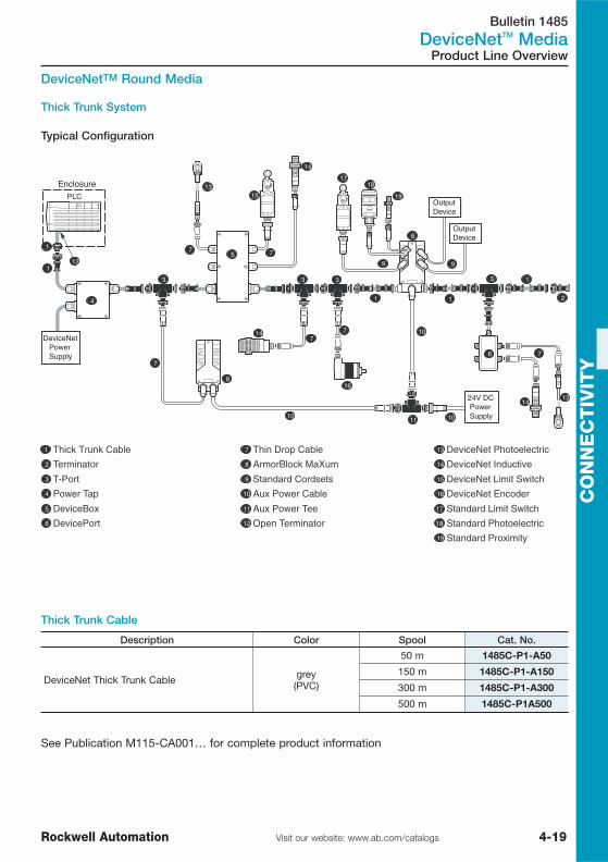
Bulletin 1485
DeviceNetTM Media
4-19Visit our website: www.ab.com/catalogsRockwell Automation
CO
NN
EC
TIV
ITY
Product Line Overview
DeviceNetTM Round Media
Thick Trunk System
Typical Configuration
1
2
3
4
5
1
1
1
3
6
7
8
10
11
99
10
7
12
1315
16
1817
7
7
8
7
19
7
13
14
3 3
1
10
14
14
1 Thick Trunk Cable2 Terminator
3 T-Port4 Power Tap
5 DeviceBox6 DevicePort
7 Thin Drop Cable8 ArmorBlock MaXum
9 Standard Cordsets10 Aux Power Cable
11 Aux Power Tee12 Open Terminator
13 DeviceNet Photoelectric14 DeviceNet Inductive
15 DeviceNet Limit Switch16 DeviceNet Encoder
17 Standard Limit Switch18 Standard Photoelectric19 Standard Proximity
DeviceNet Power Supply
PLC
Enclosure
Output Device
24V DC Power Supply
Output Device
Thick Trunk Cable
Description Color Spool Cat. No.
DeviceNet Thick Trunk Cable grey(PVC)
50 m 1485C-P1-A50
150 m 1485C-P1-A150
300 m 1485C-P1-A300
500 m 1485C-P1A500
See Publication M115-CA001… for complete product information
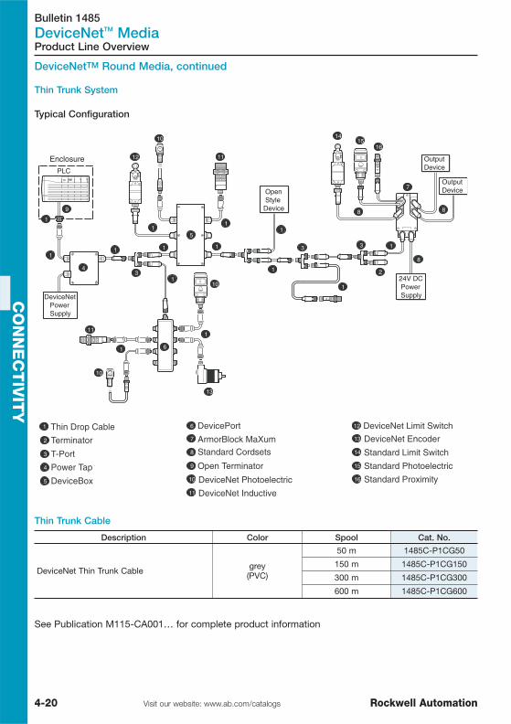
Bulletin 1485
DeviceNetTM Media
4-20 Visit our website: www.ab.com/catalogs Rockwell Automation
CO
NN
EC
TIV
ITY
Product Line Overview
DeviceNetTM Round Media, continued
Thin Trunk System
Typical Configuration
1 Thin Drop Cable2 Terminator
3 T-Port4 Power Tap
5 DeviceBox
6 DevicePort7
8
ArmorBlock MaXum
9
Standard Cordsets
10
11
12
Open Terminator
13
DeviceNet Photoelectric
14
DeviceNet Inductive
15
DeviceNet Limit Switch
16
DeviceNet Encoder
Standard Limit Switch
Standard Photoelectric
Standard Proximity
DeviceNet Power Supply
PLC
Enclosure
Output Device
24V DC Power Supply
Output Device
Open StyleDevice
1
1
1
1
1
11
1
1
2
1
7
1
1
1
4
3
6
5
8
89
12
10
13
11
11
1415
16
10
13
10
3
8
Thin Trunk Cable
Description Color Spool Cat. No.
DeviceNet Thin Trunk Cable grey(PVC)
50 m 1485C-P1CG50
150 m 1485C-P1CG150
300 m 1485C-P1CG300
600 m 1485C-P1CG600
See Publication M115-CA001… for complete product information

Bulletin 1485
DeviceNetTM Media
4-21Visit our website: www.ab.com/catalogsRockwell Automation
CO
NN
EC
TIV
ITY
Accessories
DeviceNetTM Round Media, continued
Description Cat. No.
Thick Trunk System
Power Tap (Thick Trunk) 7.5 A Fuse (2 included) 1485T-P2T5-T5
2-port DeviceBox Tap, Thick Trunk, Cable GlandConnections 2 Drops 1485P-P2T5-T5
4-port DeviceBox Tap, Thick Trunk, Cable GlandConnections 4 Drops 1485P-P4T5-T5
8-port DeviceBox Tap, Thick Trunk, Cable GlandConnections 8 Drops 1485P-P8T5-T5
Thin Trunk System
Power Tap (Thin Trunk) 3 A Fuse (2 included) 1485T-P2T5-T5C
2-port DeviceBox Tap (Thin Trunk). 2 Drops 1485P-P2T5-T5C
4-port DeviceBox Tap (Thin Trunk). 4 Drops 1485P-P4T5-T5C
8-port DeviceBox Tap (Thin Trunk). 8 Drops 1485P-P8T5-T5C
Description Trunk Drop Cat. No.
4-port DeviceNet Thru-Trunk DevicePort Mini MiniFemale 1485P-P4N5-MN5
6-port DeviceNet Thru-Trunk DevicePort Mini MiniFemale 1485P-P6N5-MN5
4-port DeviceNet Thru-Trunk DevicePort Mini MicroFemale 1485P-P4R5-MN5
6-port DeviceNet Thru-Trunk DevicePort Mini MicroFemale 1485P-P6R5-MN5
See Publication M115-CA001… for complete product information

Bulletin 1485
DeviceNetTM Media
4-22 Visit our website: www.ab.com/catalogs Rockwell Automation
CO
NN
EC
TIV
ITY
Accessories
DeviceNetTM Round Media �, continued
Description Trunk Drop Cat. No.
DeviceNet T-Port with Trunk and Dropconnections Left Keyway Micro Micro 1485P-P1R5-DR5
DeviceNet T-Port with Mini Trunk and MicroDrop connections Right Keyway Mini Micro 1485P-P1R5-
MN5R1
Description Cable Cat. No.
Pre-terminated Thin Cable: Right Angle MicroMale to Straight Micro Female: 1 m (3.3ft)
yellow(CPE)
1485R-P1R5-F5
Pre-terminated Thin Cable: Right Angle MicroMale to Straight Micro Female: 2 m (6.5ft) 1485R-P2R5-F5
Pre-terminated Thin Cable: Right Angle MicroMale to Straight Micro Female: 3 m (9.8ft) 1485R-P3R5-F5
Pre-terminated Thin Cable: Right Angle MicroMale to Straight Micro Female: 4m (13.1ft) 1485R-P4R5-F5
Pre-terminated Thin Cable: Right Angle MicroMale to Straight Micro Female: 5m (16.4ft) 1485R-P5R5-F5
Pre-terminated Thin Cable: Right Angle MicroMale to Straight Micro Female: 6m (19.8ft) 1485R-P6R5-F5
Pre-terminated Thin Cable: Straight Micro Maleto Straight Micro Female: 1 m (3.3ft)
yellow(CPE)
1485R-P1R5-D5
Pre-terminated Thin Cable: Straight Micro Maleto Straight Micro Female: 2 m (6.5ft) 1485R-P2R5-D5
Pre-terminated Thin Cable: Straight Micro Maleto Straight Micro Female: 3 m (9.8ft) 1485R-P3R5-D5
Pre-terminated Thin Cable: Straight Micro Maleto Straight Micro Female: 4 m (13.1ft) 1485R-P4R5-D5
Pre-terminated Thin Cable: Straight Micro Maleto Straight Micro Female: 5m (16.4ft) 1485R-P5R5-D5
Pre-terminated Thin Cable: Straight Micro Maleto Straight Micro Female: 6m (13.1ft) 1485R-P6R5-D5
� For use with distributed starters. See publication M115-CA001… for complete cable selection information.

Bulletin 1485
DeviceNetTM Media
4-23Visit our website: www.ab.com/catalogsRockwell Automation
CO
NN
EC
TIV
ITY
Accessories
DeviceNetTM Round Media �, continued
Description Trunk Drop Cat. No.
DeviceNet T-Port with Mini Trunk and Mini Dropconnections Left Keyway Mini Mini 1485P-P1N5-
MN5L1
DeviceNet T-Port with Mini Trunk and Mini Dropconnections Right Keyway Mini Mini 1485P-P1N5-
MN5R1
Description Cable Cat. No.
DeviceNet Thick Trunk or Drop Cable
grey(PVC)
1485C-P1N5-M5
DeviceNet Thick Trunk or Drop Cable 1485C-P3N5-M5
DeviceNet Thick Trunk or Drop Cable 1485C-P5N5-M5
DeviceNet Thick Trunk Cable 1485C-P10N5-M5
DeviceNet Thick Trunk Cable 1485C-P30N5-M5
DeviceNet Mini Male to Micro Female1 m (3.28 ft.)
yellow(CPE)
1485R-P1M5-R5
DeviceNet Mini Male to Micro Female2 m (6.56 ft.) 1485R-P2M5-R5
DeviceNet Mini Male to Micro Female3 m (9.84 ft.) 1485R-P3M5-R5
Pre-terminated Thin Cable: Straight Mini Male toStraight Micro Female: 4m (13.1ft) 1485R-P4M5-R5
� For use with distributed starters. See publication M115-CA001… for complete cable selection information.
See Publication M115-CA001… for complete product information
Other styles (connectors, cordsets and patchcords) and lengths are available, please consult yourlocal Rockwell Automation distributor for details.

Bulletin 1485
DeviceNetTM Media
4-24 Visit our website: www.ab.com/catalogs Rockwell Automation
CO
NN
EC
TIV
ITY
Accessories
DeviceNetTM Round Media, continued
Terminal Chambers
Terminal chambers are passive field-installable connectors. Allen-Bradley 5-pin micro style and 5-pinmini style terminal chambers are designed for use with DeviceNet systems. These connectorscontain screw terminals for quick and easy installation and are sized for use with either DeviceNetthick or thin cables.
Description Media Use Connector Cat. No.
5-pin Straight Mini MaleTerminal Chamber, Thick,screw type
Thick
Straight Mini Male 871A-TS5-NM3
5-pin Straight Mini FemaleTerminal Chamber, Thick,screw type
Straight Mini Female 871A-TS5-N3
5-pin Straight TerminalChamber
ThinStraight Mini Male 871A-TS5-NM1
5-pin Straight TerminalChamber Straight Mini Female 871A-TS5-N1
5-pin Straight TerminalChamber
ThinStraight DC Micro Male 871A-TS5-DM1
5-pin Straight TerminalChamber Straight DC Micro Female 871A-TS5-D1
5-pin Right Angle TerminalChamber
ThinRight Angle DC Micro Male 871A-TR5-DM1
5-pin Right Angle TerminalChamber
Right Angle DC MicroFemale 871A-TR5-D1
Terminators
Description Media Use Cat. No.
Micro Terminator, Male
Thick or Thin
1485A-T1M5
Micro Terminator, Female 1485A-T1N5
Micro Terminator, Male
Thick
1485A-T1D5
Micro Terminator, Female 1485A-T1R5

Bulletin 1485
DeviceNetTM Media
4-25Visit our website: www.ab.com/catalogsRockwell Automation
CO
NN
EC
TIV
ITY
Accessories
DeviceNetTM Round Media, continued
Open Style Connectors
Description Cat. No.
DeviceNet Terminal Block AssemblyWith color coded double tier terminals 1492-DN3TW
5-pin Linear Plug, Open-style 1799-DNETCON
5-pin Linear Plug, Open-style, with Jack Screws 1799-DNETSCON
Open-style, 10-position Linear Plug 1787-PLUG10R
Thin Trunk System
Terminating Resistor 1485A-C2
Accessory Kit for DeviceBox 1485A-ACCKIT
Bulkhead Pass-thru
Description Media Use Cat. No.
Mini 5-pin Bulkhead Pass-thru Thick or Thin 1485A-CXN5-M5
Micro 5-pin Bulkhead Pass-thru Thin 1485A-CXR5-D5
See Publication M115-CA001… for complete product information
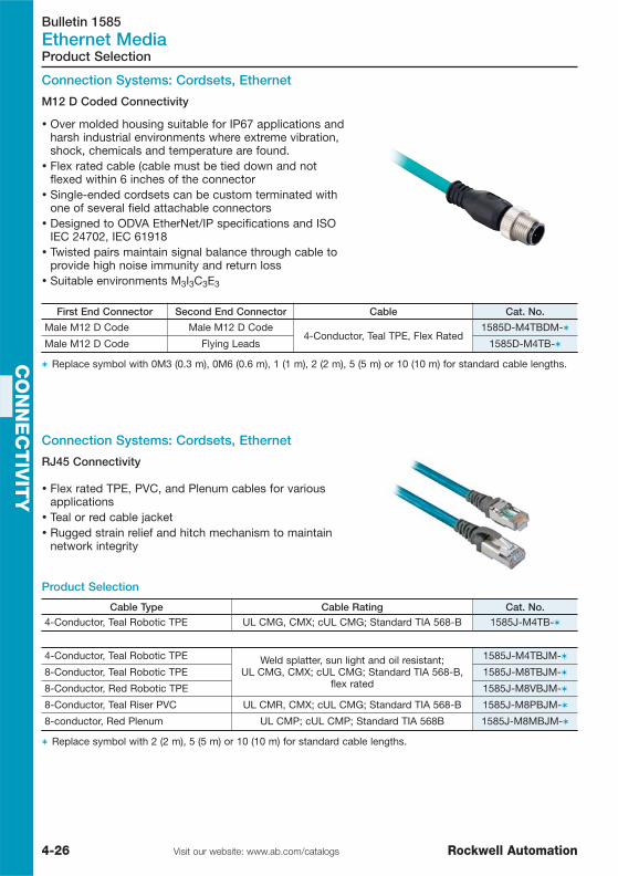
Bulletin 1585Ethernet Media
4-26 Visit our website: www.ab.com/catalogs Rockwell Automation
CO
NN
EC
TIV
ITY
Product Selection
Connection Systems: Cordsets, Ethernet
M12 D Coded Connectivity
� Over molded housing suitable for IP67 applications andharsh industrial environments where extreme vibration,shock, chemicals and temperature are found.
� Flex rated cable (cable must be tied down and notflexed within 6 inches of the connector
� Single-ended cordsets can be custom terminated withone of several field attachable connectors
� Designed to ODVA EtherNet/IP specifications and ISOIEC 24702, IEC 61918
� Twisted pairs maintain signal balance through cable toprovide high noise immunity and return loss
� Suitable environments M3I3C3E3
First End Connector Second End Connector Cable Cat. No.
Male M12 D Code Male M12 D Code4-Conductor, Teal TPE, Flex Rated
1585D-M4TBDM-�
Male M12 D Code Flying Leads 1585D-M4TB-�
� Replace symbol with 0M3 (0.3 m), 0M6 (0.6 m), 1 (1 m), 2 (2 m), 5 (5 m) or 10 (10 m) for standard cable lengths.
Connection Systems: Cordsets, Ethernet
RJ45 Connectivity
� Flex rated TPE, PVC, and Plenum cables for variousapplications
� Teal or red cable jacket� Rugged strain relief and hitch mechanism to maintain
network integrity
Product Selection
Cable Type Cable Rating Cat. No.4-Conductor, Teal Robotic TPE UL CMG, CMX; cUL CMG; Standard TIA 568-B 1585J-M4TB-�
4-Conductor, Teal Robotic TPE Weld splatter, sun light and oil resistant;UL CMG, CMX; cUL CMG; Standard TIA 568-B,
flex rated
1585J-M4TBJM-�
8-Conductor, Teal Robotic TPE 1585J-M8TBJM-�
8-Conductor, Red Robotic TPE 1585J-M8VBJM-�
8-Conductor, Teal Riser PVC UL CMR, CMX; cUL CMG; Standard TIA 568-B 1585J-M8PBJM-�
8-conductor, Red Plenum UL CMP; cUL CMP; Standard TIA 568 B 1585J-M8MBJM-�
� Replace symbol with 2 (2 m), 5 (5 m) or 10 (10 m) for standard cable lengths.
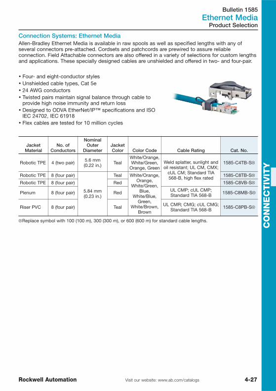
Bulletin 1585Ethernet Media
4-27Visit our website: www.ab.com/catalogsRockwell Automation
CO
NN
EC
TIV
ITY
Product Selection
Connection Systems: Ethernet MediaAllen-Bradley Ethernet Media is available in raw spools as well as specified lengths with any ofseveral connectors pre-attached. Cordsets and patchcords are prewired to assure reliableconnection. Field Attachable connectors are also offered in a variety of selections for custom lengthsand applications. These specially designed cables are unshielded and offered in two- and four-pair.
� Four- and eight-conductor styles� Unshielded cable types, Cat 5e� 24 AWG conductors� Twisted pairs maintain signal balance through cable to
provide high noise immunity and return loss� Designed to ODVA EtherNet/IP™ specifications and ISO
IEC 24702, IEC 61918� Flex cables are tested for 10 million cycles
JacketMaterial
No. ofConductors
NominalOuter
DiameterJacketColor Color Code Cable Rating Cat. No.
Robotic TPE 4 (two pair) 5.6 mm(0.22 in.) Teal
White/Orange,White/Green,
Orange, GreenWeld splatter, sunlight andoil resistant; UL CM, CMX;
cUL CM; Standard TIA568-B, high flex rated
1585-C4TB-S⊗
Robotic TPE 8 (four pair)
5.84 mm(0.23 in.)
Teal White/Orange,Orange,
White/Green,Blue,
White/Blue,Green,
White/Brown,Brown
1585-C8TB-S⊗
Robotic TPE 8 (four pair) Red 1585-C8VB-S⊗
Plenum 8 (four pair) Red UL CMP; cUL CMP;Standard TIA 568-B 1585-C8MB-S⊗
Riser PVC 8 (four pair) Teal UL CMR; CMG; cUL CMG;Standard TIA 568-B 1585-C8PB-S⊗
⊗Replace symbol with 100 (100 m), 300 (300 m), or 600 (600 m) for standard cable lengths.

Bulletin 1585Ethernet Media
4-28 Visit our website: www.ab.com/catalogs Rockwell Automation
CO
NN
EC
TIV
ITY
Product Selection
Connection Systems: EtherNet™IDC Connector
RJ45 Insulation DisplacementConnector (IDC)
RJ45 Crimp
� 26-22 AWG Conductors� 360° Shielding� Re-use IDC Connector Up to Five Times� No Tools or Conductor Stripping Required� Cat. 6
Crimp Connector
� 26…24 AWG� Standard Crimp Connector with Rugged Boot� Cat. 5e
DescriptionElectrical
ConnectionHousingMaterial
InsulationMaterial
ContactMaterial
ChannelBandwidth Cat. No.
RJ45 InsulationDisplacementConnector (IDC)
— Diecast Zinc
Plastic Copper alloy
Cat. 6 1585J-M8CC-H
RJ45 CrimpConnector withBoot
150V, 1.5 A ClearPolycarbonate Cat. 5e � 1585J-M8CC-C
�Qty. = 50 pieces
Ethernet M12 MediaInsulation Displacement Connector (IDC)� Feld installable with no hand tools needed� Straight male or female shielded versions� Allows easy modification of existing cable installations� Insulation displacement technology for secure and reliable installation� Metal body unit excellent in shielding applications
4-Pin, M12 Receptacle & M12 to RS45 Adaptor� #24 AWG conductors� 4-pin D-coded M12 configuration� M12 to RS45 bulkhead� IP67
Description Mounting Assembly Rating Cat. No.
Female M12 receptacle toRJ45 female adaptor right
anglePG 9 Panel Mount Threads
#22 AWG32V4 A
1585A-DD4JD
No. of PinsConnector
MaterialCable Diameter
[mm (in.)] Wire SizeAssembly
RatingConnector
Style Cat. No.
4 Polyamide smallbody unshielded
4.0…5.1(0.16…0.20)
#26…22AWG 32V, 4 A Straight Male 1585D-M4DC-H

Bulletin 1783Ethernet Media
4-29Visit our website: www.ab.com/catalogsRockwell Automation
CO
NN
EC
TIV
ITY
Product Selection
Stratix 2000 UnmanagedThe Stratix 2000 unmanaged line scales from 4 to 8 ports and offers a variety of copper and fiberoptions. Stratix 2000 unmanaged switches are easy to apply, requiring no configuration.Complementary IP67, managed and Enterprise integrated switches will fill out the Ethernet switchportfolio.
� Optimized for small, isolated networks� Requires no configuration� Auto negotiation� Auto crossing
DescriptionPower
RequirementsOperating
Temp.Dimensions
(H, W, D) [mm] Cat. No.
4 copper ports, 1fiber with LC-connector 10…35V DC 0…60 °C 28x108x127 1783-US03T01F
5 copper ports 10…35V DC 0…60 °C 28x108x127 1783-US05T
7 copper ports, 1fiber with LC-connector 10…35V DC 0…60 °C 45x108x127 1783-US06T01F
8 copper ports 10…35V DC 0…60 °C 45x108x127 1783-US08T

Bulletin 1790D, 1791D, 1732Distributed I/O
4-30 Visit our website: www.ab.com/catalogs Rockwell Automation
CO
NN
EC
TIV
ITY
Product Line Overview
Bulletin 1790D 1732
Type CompactBlock LDX Distributed I/O ArmorBlock I/O
Features
� Wide breadth of I/O types that canhandle diverse applications
� Expandable up to 3 digital expansionblocks (80 I/O's)
� Universal sink/source inputs reduces thenumber of components to stock andallows flexibility of input types
� Selectable termination types (D-shell orscrew)
� Easy to connect and configure usingmodular EDS files
� ODVA conformance ensures high level ofinteroperability with other DeviceNetproducts
� Analog DeviceNet bases for current,voltage, PT100 and thermocoupleexecution
� CompactBlock LDX I/O are also availablefor other network
� 24V DC, 120V AC and relay discreteblocks with built-in DeviceNet adapter
� Cyclic and change-of-state messagingincreases network throughput, increasesproductivity
� Auto baud rate detection
� Sealed housing rated for IP67K andNEMA 4X eliminate enclosure costs
� I/O connectors are sealed M8 pico orM12 DC micro styles
� 8-point and 16-point self-configuring I/Oprovides flexibility for any input/outputcombination
� Removal and Insertion Under Powerallows module replacement withoutimpacting the network operation
� Isolated auxiliary power maintains powerto the outputs if main power fails
� Outputs electronically protected fromfailing with option to auto-restart or latchoff
� Complies with Open DeviceNet VendorAssociation, Inc. (ODVA) conformancetest software
I/O Up to 80 I/O with discrete bases and up to36 I/O with analog bases 8 or 16 digital points
Analog Inputs/Outputs
4 & 2 (Voltage/Current/RTD/Thermocouple)
⎯
Software RSNetworx for DeviceNet
Mounting Horizontal / Vertical Panel or DIN railmounted On-Machine Panel
Operating Power 120V AC / 24V DC 24V DC
Standards/Approvals UL/cUL Listed, CE certified IP65, IP66, IP67K, NEMA 4X, cULus, CE,
C-Tick
Product Selection See page 4-31 See page 4-33

Bulletin 1790DDistributed I/O
4-31Visit our website: www.ab.com/catalogsRockwell Automation
CO
NN
EC
TIV
ITY
DeviceNet Bases
Product Selection
� Small, easy expandable block I/O products withuniversal sink/source inputs
� Digital bases support up to 3 discrete expansionblocks (80 I/O's) and analog bases support up to 2discrete expansion blocks
� Cost-effective I/O product line for light industrial andcommercial automation
� Selectable terminations (D-shell or screwterminations)
� Wide breadth of I/O's including discrete, analog,thermopcouple and RTD bases for different networksand discrete expansion blocks
Discrete I/O
CompactBlock LDX I/O Blocks
Description Cat. No.
DNet LDX, 16 sourcing output base, D-shell connector 1790D-0B16
DNet LDX, 24V DC, 16 sinking output base, D-shell connector 1790D-0V16
DNet LDX, 6 relay output base, D-shell connector 1790D-0W6
DNet LDX, 24V DC, 16 universal input base, D-shell 1790D-16BV0
DNet LDX, 24V DC, 32 universal input base, D-shell 1790D-T32BV0
DNet LDX, 24V DC, 8 univ In/8 source output base, D-shell 1790D-8BV8B
DNet LDX, 24V DC, 8 univ In/8 sink output base, D-shell 1790D-8BV8V
DNet LDX,120V AC, 6 output base, terminal block 1790D-T0A6
DNet LDX, 24V DC, 16 source output base, terminal block 1790D-T0B16
DNet LDX, 24V DC, 32 source output base, terminal block 1790D-T0B32
DNet LDX, 24V DC, 16 sinking output base, terminal block 1790D-T0V16
DNet LDX, 24V DC, 32 sinking output base, terminal block 1790D-T0V32
DNet LDX, 6 relay output base, terminal block 1790D-T0W6
DNet LDX, 24V DC, 16 universal input base, terminal block 1790D-T16BV0
DNet LDX, 120V AC, 8 input base, terminal block 1790D-T8A0
DNet LDX, 24V DC, 8 univ in/8 source output base, terminal block 1790D-T8BV8B
DNet LDX, 24V DC, 16 univ in/16 source output base, terminal block 1790D-T16BV16B
DNet LDX, 24V DC, 8 univ in/8 sink output base, terminal block 1790D-T8BV8V
DNet LDX, 24V DC, 16 univ in/16 sink output base, terminal block 1790D-T16BV16V

Bulletin 1790DDistributed I/O
4-32 Visit our website: www.ab.com/catalogs Rockwell Automation
CO
NN
EC
TIV
ITY
Description Cat. No.
LDX I/O, 24V DC, 16 source out expansion, D-shell 1790-0B16X
LDX I/O, 24V DC, 16 sink out expansion, D-shell 1790-0V16X
LDX I/O, 8 relay out, expansion, D-shell 1790-0W8X
LDX I/O, 24V DC, 16 universal in expansion, D-shell 1790-16BV0X
LDX I/O, 24V DC, 8 univ in/8 source out expansion, D-shell 1790-8BV8BX
LDX I/O, 24V DC, 8 univ in/8 sink out expansion, D-shell 1790-8BV8VX
LDX I/O,120V AC, 8 output expansion module, terminal block 1790-T0A8X
LDX I/O, 24V DC, 16 source out expansion, terminal block 1790-T0B16X
LDX I/O, 24V DC, 16 sink out expansion, terminal block 1790-T0V16X
LDX I/O, 8 relay out, expansion, terminal block 1790-T0W8X
LDX I/O, 24V DC, 16 universal in expansion, terminal block 1790-T16BV0X
LDX I/O,120V AC, 8 input expansion module, terminal block 1790-T8A0X
LDX I/O, 24V DC, 8 univ in/8 source out expansion, terminal block 1790-T8BV8BX
LDX I/O, 24V DC, 8 univ in/8 sink out expansion, terminal block 1790-T8BV8VX
Expansion Block I/O
Product Selection
CompactBlock LDX I/O Blocks, continued
Analog I/ODeviceNet Bases
Description Cat. No.
DeviceNet LDX, 4 input RTD base, D-shell connector 1790D-4R0
DeviceNet LDX, 4 input thermocouple base, D-shell connector 1790D-4T0
DeviceNet LDX, 2 output analog current base, D-shell connector 1790D-N0C2
DeviceNet LDX, 2 output voltage analog base, D-shell connector 1790D-N0V2
DeviceNet LDX, 4 input analog current base, D-shell connector 1790D-N4C0
DeviceNet LDX, 4 input voltage analog base, D-shell connector 1790D-N4V0
DeviceNet LDX, 4 input RTD base, terminal block 1790D-T4R0
DeviceNet LDX, 4 input thermocouple base, terminal block 1790D-T4T0
DeviceNet LDX, 2 output analog current base, terminal block 1790D-TN0C2
DeviceNet LDX, 2 output voltage analog base, terminal block 1790D-TN0V2
DeviceNet LDX, 4 input analog current base, terminal block 1790D-TN4C0
DeviceNet LDX, 4 input voltage analog base, terminal block 1790D-TN4V0
See publication 1790-PP002… or 1790D-TD001… for complete product information.
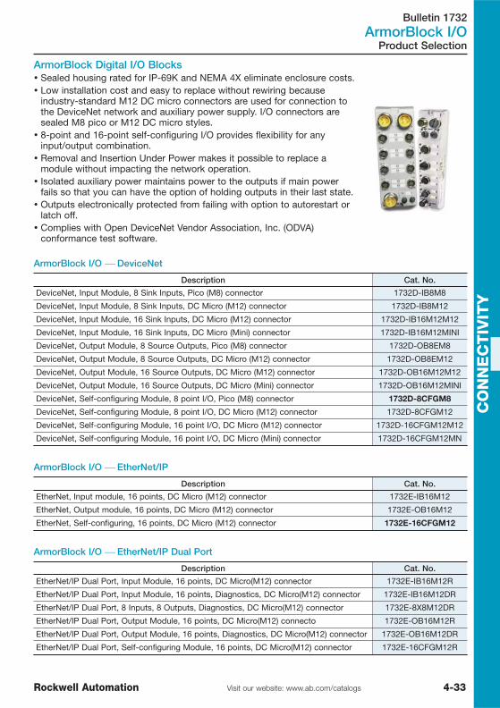
Bulletin 1732ArmorBlock I/O
4-33Visit our website: www.ab.com/catalogsRockwell Automation
CO
NN
EC
TIV
ITY
Product Selection
ArmorBlock Digital I/O Blocks� Sealed housing rated for IP-69K and NEMA 4X eliminate enclosure costs.� Low installation cost and easy to replace without rewiring because
industry-standard M12 DC micro connectors are used for connection tothe DeviceNet network and auxiliary power supply. I/O connectors aresealed M8 pico or M12 DC micro styles.
� 8-point and 16-point self-configuring I/O provides flexibility for anyinput/output combination.
� Removal and Insertion Under Power makes it possible to replace amodule without impacting the network operation.
� Isolated auxiliary power maintains power to the outputs if main powerfails so that you can have the option of holding outputs in their last state.
� Outputs electronically protected from failing with option to autorestart orlatch off.
� Complies with Open DeviceNet Vendor Association, Inc. (ODVA)conformance test software.
ArmorBlock I/O ⎯ DeviceNet
Description Cat. No.
DeviceNet, Input Module, 8 Sink Inputs, Pico (M8) connector 1732D-IB8M8
DeviceNet, Input Module, 8 Sink Inputs, DC Micro (M12) connector 1732D-IB8M12
DeviceNet, Input Module, 16 Sink Inputs, DC Micro (M12) connector 1732D-IB16M12M12
DeviceNet, Input Module, 16 Sink Inputs, DC Micro (Mini) connector 1732D-IB16M12MINI
DeviceNet, Output Module, 8 Source Outputs, Pico (M8) connector 1732D-OB8EM8
DeviceNet, Output Module, 8 Source Outputs, DC Micro (M12) connector 1732D-OB8EM12
DeviceNet, Output Module, 16 Source Outputs, DC Micro (M12) connector 1732D-OB16M12M12
DeviceNet, Output Module, 16 Source Outputs, DC Micro (Mini) connector 1732D-OB16M12MINI
DeviceNet, Self-configuring Module, 8 point I/O, Pico (M8) connector 1732D-8CFGM8
DeviceNet, Self-configuring Module, 8 point I/O, DC Micro (M12) connector 1732D-8CFGM12
DeviceNet, Self-configuring Module, 16 point I/O, DC Micro (M12) connector 1732D-16CFGM12M12
DeviceNet, Self-configuring Module, 16 point I/O, DC Micro (Mini) connector 1732D-16CFGM12MN
ArmorBlock I/O ⎯ EtherNet/IP
Description Cat. No.
EtherNet, Input module, 16 points, DC Micro (M12) connector 1732E-IB16M12
EtherNet, Output module, 16 points, DC Micro (M12) connector 1732E-OB16M12
EtherNet, Self-configuring, 16 points, DC Micro (M12) connector 1732E-16CFGM12
ArmorBlock I/O ⎯ EtherNet/IP Dual Port
Description Cat. No.
EtherNet/IP Dual Port, Input Module, 16 points, DC Micro(M12) connector 1732E-IB16M12R
EtherNet/IP Dual Port, Input Module, 16 points, Diagnostics, DC Micro(M12) connector 1732E-IB16M12DR
EtherNet/IP Dual Port, 8 Inputs, 8 Outputs, Diagnostics, DC Micro(M12) connector 1732E-8X8M12DR
EtherNet/IP Dual Port, Output Module, 16 points, DC Micro(M12) connecto 1732E-OB16M12R
EtherNet/IP Dual Port, Output Module, 16 points, Diagnostics, DC Micro(M12) connector 1732E-OB16M12DR
EtherNet/IP Dual Port, Self-configuring Module, 16 points, DC Micro(M12) connector 1732E-16CFGM12R

Bulletin 1732ArmorBlock I/O
4-34 Visit our website: www.ab.com/catalogs Rockwell Automation
CO
NN
EC
TIV
ITY
The Cable and Cordset tables list the most common cable, patchcords, and cordsets for the I/Omodule.You can also find additional information on selecting cables and cordsets for ArmorBlock I/O in thesepublications:
ArmorBlock I/O Cables
Product Selection
Cables and Cordsets
� On-Machine Connectivity Cataloghttp://literature.rockwellautomation.com/idc/groups/literature/documents/ca/m116-ca001_-en-p.pdf
� On-Machine Solutions Selection Guidehttp://literature.rockwellautomation.com/idc/groups/literature/documents/sg/onmach-sg001_-en-p.pdf
For Using:Recommended Patchcord
(double-ended)
Recommended MaleCordset
(single-ended) Cat. No.
2 inputs per connector 879D-F4ACDM-x 879-C3AEDM4-51732D-IB8M12
1 input per connector 889D-F4ACDM-x 889D-M4AC-x
3-pin pico connectors 889P-F3ABPM-x889P-M3AB-y 1732D-IB8M8
4-pin pico connectors 889P-F4ABPM3-x
2 inputs per connector 879D-F4ACDM-x879-C3AEDM4-5 1732D-OB8EM12
1 input per connector 889D-F4ACDM-x
3-pin pico connectors 889P-F3ABPM-x 889P-M3AB-y1732D-OB8EM8
4-pin pico connectors 889P-F4ABPM3-x 889P-M3AB-y
2 inputs per connector 879D-F4ACDM-x 879-C3AEDM4-51732D-8CFGM12
1 input per connector 889D-F4ACDM-x 889D-M4AC-x
3-pin pico connectors 889P-F3ABPM-x889P-M3AB-y 1732D-8CFGM8
4-pin pico connectors 889P-F4ABPM3-x
x = length in meters (1, 2, 3, 5, and 10 standard).y = length in meters (2, 5, and 10 standard).
ArmorBlock DeviceNet and Auxiliary Power Cables
Recommended DeviceNet Cable Recommended Auxiliary Power Cables Cat. No.
KwikLink Flat Media system standard dropcable:
1485K-PzF5-R5Thick Round system standard drop cable:
1485R-PzM5-R5Thin Round system standard drop or trunk:
1485R-PzR5-D5
Standard Cordset (single-ended):889D-F4AC-y
Standard Patchcord (double-ended):889D-F4ACDM-x
1732D-IB8M12
1732D-IB8M8
1732D-OB8EM12
1732D-OB8EM8
1732D-8CFGM12
1732D-8CFGM8
x = length in meters (1, 2, 3, 5, and 10 standard).y = length in meters (2, 5, and 10 standard).

Bulletin 889D, 889R, 889N, 889P, 898D & 898P, 871A & 889DConnection Systems
4-35Visit our website: www.ab.com/catalogsRockwell Automation
CO
NN
EC
TIV
ITY
Bulletin 898D and 898P 871A and 889D
Type DC Micro and Pico Distribution Boxes DC Micro Field Attachable Connectors
Features
� 4-pin DC micro or 3-pin pico connectors� Top mount inputs� 4- or 8-port parallel wired� PNP wired LED versions� Single input per port� Prewired master cable� Rugged grey Pocan body
� 4-pin connector� Male and female versions� Screw terminal or insulation displacement
connection� Glass filled nylon connector body� Supports cable O.D.s from 4…8 mm
Product Selection See page 4-41 See page 4-42
Cable Selection
Product Line Overview
Bulletin 889D 889R 889N 889P
TypeDC Micro QD / M12
Cordsetsand Patchcords
AC Micro QD / M12Cordsets Mini QD Cordsets
Pico QD / M8Cordsets
and Patchcords
Features
� 4-, 5- and 8-pinconnectors
� Straight or rightangle versions
� 22 AWG or 24 AWGcable
� Oil resistant yellowor black PVC jacket
� 3-, 4-, 5- and 6-pinconnectors
� Straight or rightangle femaleconnector
� Standard 18 AWGcable
� Oil resistant yellowPVC jacket
� 3-, 4-, and 5-pinconnectors
� Straight or rightangle versions
� Heavy dutySTOOW 16 AWGcable
� Oil resistant yellowPVC jacket
� 3- or 4-pinconnectors
� Straight or rightangle female
� Standard 24 AWGcable
� Oil resistant yellowPVC jacket
Product Selection See page 4-36 See page 4-38 See page 4-39 See page 4-40

Bulletin 889DConnection Systems
4-36 Visit our website: www.ab.com/catalogs Rockwell Automation
CO
NN
EC
TIV
ITY
� 8-pin/8-wire configurations for GuardShield safety lightcurtains and other applications
� Ratching coupling nuts for vibration resistance
DC Micro QD / M12 Cordsets
Product Selection
DC Micro QD / M12 Cordsets, Shielded
DC Micro QD / M12 Cordsets
� 4- and 5-pin DC micro style (M12)� UL recognized and CSA certified� Highly visible yellow PVC jacket offers good oil and chemical
resistance� Ratcheting coupling nut for vibration resistance
Connector Style
Cable
Cat. No.Wire Color Wire Rating Length [m (ft)]
Straight1 Brown2 White3 Blue4 Black 22 AWG
300V4 A
2 (6.5) 889D-F4AC-2
5 (16.4) 889D-F4AC-5
10 (32.8) 889D-F4AC-10
Right Angle
2 (6.5) 889D-R4AC-2
5 (16.4) 889D-R4AC-5
10 (32.8) 889D-R4AC-10
Straight, Unshielded
1 Brown2 White3 Blue4 Black5 Grey
2 (6.5) 889D-F5AC-2
5 (16.4) 889D-F5AC-5
10 (32.8) 889D-F5AC-10
Connector Style
Cable
Cat. No.Wire Color Wire Rating Length [m (ft)]
Straight Female
1 Brown2 White3 Blue4 Black
300V4 A 2 (6.5) 889D-F4EC-2
Connector Style
Cable
Cat. No.Wire Color Wire Rating Length [m (ft)]
Straight Female
1 White2 Brown3 Green4 Yellow5 Grey6 Pink7 Blue8 Red
24 AWG30V AC/36V DC
1.5 A
2 (6.5) 889D-F8AB-2
5 (16.4) 889D-F8AB-5
10 (32.8) 889D-F8AB-10
Above cordsets also with "Right Angle" connector available, for example: 889D-R8AB-_

Bulletin 889DConnection Systems
4-37Visit our website: www.ab.com/catalogsRockwell Automation
CO
NN
EC
TIV
ITY
Patchcords, DC Micro QD / M12 Style
Female(Sensor End)
Connector Style
CableMale (I/O End)
Connector Style Cat. No.Wire Rating Length [m (ft)]
Straight
22 AWG300V4 A
1 (3.3)
Straight
889D-F4ACDM-1
2 (6.5) 889D-F4ACDM-2
5 (16.4) 889D-F4ACDM-5
10 (32.8) 889D-F4ACDM-10
1 (3.3)
Right Angle
889D-F4ACDE-1
2 (6.5) 889D-F4ACDE-2
5 (16.4) 889D-F4ACDE-5
10 (32.8) 889D-F4ACDE-10
Right Angle
1 (3.3)
Straight
889D-R4ACDM-1
2 (6.5) 889D-R4ACDM-2
5 (16.4) 889D-R4ACDM-5
10 (32.8) 889D-R4ACDM-10
1 (3.3)
Right Angle
889D-R4ACDE-1
2 (6.5) 889D-R4ACDE-2
5 (16.4) 889D-R4ACDE-5
10 (32.8) 889D-R4ACDE-10
Straight
1 (3.3)
Straight
889D-F5ACDM-1
2 (6.5) 889D-F5ACDM-2
5 (16.4) 889D-F5ACDM-5
10 (32.8) 889D-F5ACDM-10
Product Selection
� 4- or 5-pin DC micro style (M12)� UL recognized and CSA certified� Highly visible yellow PVC jacket offers good oil and chemical
resistance� Ratcheting coupling nut for vibration resistance

Bulletin 889RConnection Systems
4-38 Visit our website: www.ab.com/catalogs Rockwell Automation
CO
NN
EC
TIV
ITY
Connector Style
Cable
Cat. No.Wire Color Wire Rating Length [m (ft)]
Straight1 Green (GND)2 Red/Black Tr.3 Red/White Tr.
Braided 22 AWGBraided 22 AWG
250V4 A
2 (6.5) 889R-F3ECA-2
Straight
1 Green (GND)2 Red/Black Tr.3 Red/White Tr.
18 AWG250V4 A
2 (6.5) 889R-F3AEA-2
5 (16.4) 889R-F3AEA-5
10 (32.8) 889R-F3AEA-10
1 Red/Black Tr.2 Red/White Tr.3 Red4 Green (GND)
2 (6.5) 889R-F4AEA-2
5 (16.4) 889R-F4AEA-5
10 (32.8) 889R-F4AEA-10
Right Angle
1 Green (GND)2 Red/Black Tr.3 Red/White Tr.
2 (6.5) 889R-R3AEA-2
5 (16.4) 889R-R3AEA-5
10 (32.8) 889R-R3AEA-10
1 Red/Black Tr.2 Red/White Tr.3 Red4 Green (GND)
2 (6.5) 889R-R4AEA-2
5 (16.4) 889R-R4AEA-5
10 (32.8) 889R-R4AEA-10
Straight
1 Red/White Tr.2 Red3 Green4 Red/Yellow Tr.5 Red/Black Tr.
18 AWG250V4 A
2 (6.5) 889R-F5AEA-2
5 (16.4) 889R-F5AEA-5
10 (32.8) 889R-F5AEA-10
1 Red/White Tr.2 Red3 Green4 Red/Yellow Tr.5 Red/Black Tr.6 Red/Blue Tr.
Braided 22 AWG250V4 A
2 (6.5) 889R-F6ECA-2
5 (16.4) 889R-F6ECA-5
10 (32.8) 889R-F6ECA-10
AC Micro QD / M12 Cordsets
Product Selection
� 3- and 4-pin AC micro style (dual key)� Straight and right angle versions� UL recognized and CSA certified� Highly visible yellow PVC jacket offers good oil and chemical
resistance� Ratcheting coupling nut for vibration resistance

Bulletin 889NConnection Systems
4-39Visit our website: www.ab.com/catalogsRockwell Automation
CO
NN
EC
TIV
ITY
Connector Style
Cable
Cat. No.Wire Color Wire Rating Length [m (ft)]
Straight
1 Green2 Black3 White
16 AWG600V13 A
1.8 (6) 889N-F3AFC-6F
3.7 (12) 889N-F3AFC-12F
6.1 (20) 889N-F3AFC-20F
1 Black2 White3 Red
4 Green
16 AWG600V10 A
1.8 (6) 889N-F4AFC-6F
3.7 (12) 889N-F4AFC-12F
6.1 (20) 889N-F4AFC-20F
1 White2 Red
3 Green4 Orange5 Black
16 AWG600V8 A
1.8 (6) 889N-F5AFC-6F
3.7 (12) 889N-F5AFC-12F
6.1 (20) 889N-F5AFC-20F
Right Angle
1 Green2 Black3 White
16 AWG600V13 A
1.8 (6) 889N-R3AFC-6F
3.7 (12) 889N-R3AFC-12F
6.1 (20) 889N-R3AFC-20F
1 Black2 White3 Red
4 Green
16 AWG600V10 A
1.8 (6) 889N-R4AFC-6F
3.7 (12) 889N-R4AFC-12F
6.1 (20) 889N-R4AFC-20F
1 White2 Red
3 Green4 Orange5 Black
16 AWG600V8 A
1.8 (6) 889N-R5AFC-6F
3.7 (12) 889N-R5AFC-12F
6.1 (20) 889N-R5AFC-20F
Mini QD Cordsets
Product Selection
� 3-, 4- and 5-pin configurations� Straight and right angle versions� UL recognized and CSA certified� Heavy duty STOOW-A 16 AWG cable� Highly visible yellow PVC jacket offers good oil and chemical
resistance� One-piece molded body design
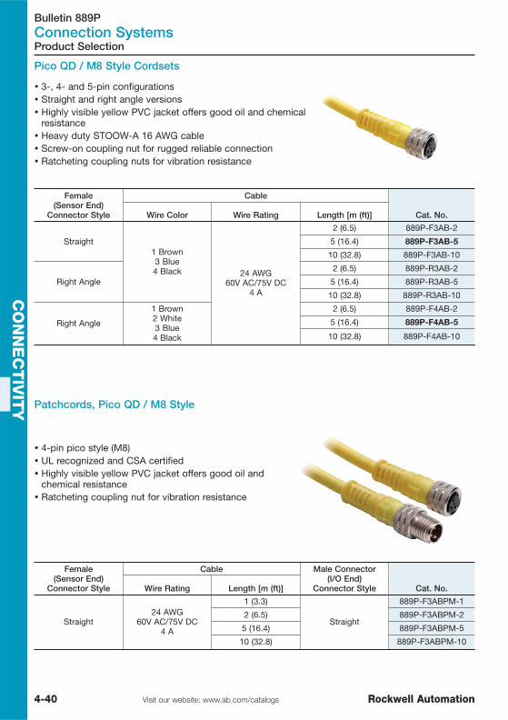
Bulletin 889PConnection Systems
4-40 Visit our website: www.ab.com/catalogs Rockwell Automation
CO
NN
EC
TIV
ITY
� 4-pin pico style (M8)� UL recognized and CSA certified� Highly visible yellow PVC jacket offers good oil and
chemical resistance� Ratcheting coupling nut for vibration resistance
Pico QD / M8 Style Cordsets
Female(Sensor End)
Connector Style
Cable
Cat. No.Wire Color Wire Rating Length [m (ft)]
Straight1 Brown3 Blue4 Black 24 AWG
60V AC/75V DC4 A
2 (6.5) 889P-F3AB-2
5 (16.4) 889P-F3AB-5
10 (32.8) 889P-F3AB-10
Right Angle
2 (6.5) 889P-R3AB-2
5 (16.4) 889P-R3AB-5
10 (32.8) 889P-R3AB-10
Right Angle
1 Brown2 White3 Blue4 Black
2 (6.5) 889P-F4AB-2
5 (16.4) 889P-F4AB-5
10 (32.8) 889P-F4AB-10
Patchcords, Pico QD / M8 Style
� 3-, 4- and 5-pin configurations� Straight and right angle versions� Highly visible yellow PVC jacket offers good oil and chemical
resistance� Heavy duty STOOW-A 16 AWG cable� Screw-on coupling nut for rugged reliable connection� Ratcheting coupling nuts for vibration resistance
Female(Sensor End)
Connector Style
Cable Male Connector(I/O End)
Connector Style Cat. No.Wire Rating Length [m (ft)]
Straight24 AWG
60V AC/75V DC4 A
1 (3.3)
Straight
889P-F3ABPM-1
2 (6.5) 889P-F3ABPM-2
5 (16.4) 889P-F3ABPM-5
10 (32.8) 889P-F3ABPM-10
Product Selection

Bulletin 898D, 898PConnection Systems
4-41Visit our website: www.ab.com/catalogsRockwell Automation
CO
NN
EC
TIV
ITY
Distribution Boxes, 4- and 8-Port Pico Style
No. of Connections Illuminated RatingsCable Length—mm
(in) Cat. No.
4LEDs (PNP)
10…30V DC2 A max/port6 A max total
5 (16.4)898P-P34PT-B5
8 898P-P38PT-B5
� 3-pin pico connectors� Top mounting holes for easier installation� LED versions for use with PNP (sourcing) field devices or
24V DC actuators
Product Selection
Distribution Boxes, 4- and 8-Port DC Micro Style
� UL recognized and CSA certified� Grey Pocan body offers good oil and chemical resistance� 4 and 8 4-pin DC micro connectors� Cable versions� LED versions for use with PNP (sourcing) field devices
No. of Connections Illuminated RatingsCable Length—mm
(in) Cat. No.
4
LEDs (PNP)10…30V DC2 A max/port
10 A max total
5 (16.4) 898D-P54PT-B5
10 (32.8) 898D-P54PT-B10
85 (16.4) 898D-P58PT-B5
10 (32.8) 898D-P58PT-B10

Bulletin 871A & 889DConnection Systems
4-42 Visit our website: www.ab.com/catalogs Rockwell Automation
CO
NN
EC
TIV
ITY
Field Attachable, DC Micro Style
� Field installable with no hand tools needed� 4-pin DC micro style� Straight male or female versions� Allows easy modification of existing cable installations� Insulation displacement technology for secure and reliable
installation
Product Selection
Terminal Chambers, DC Micro Style
� Field installable� 4-pin DC micro style (M12)� Straight or right angle versions� Screw terminals provide simple and secure installation� Allows easy modification of existing cable installations
Type Connector StyleJacket Cable Diameter
[mm (in)] Wire Rating Cat. No.
Female
Straight
—
250V, 4 A
871A-TS4-D
— 871A-TS4-D1
Male— 871A-TS4-DM
— 871A-TS4-DM1
Type Connector StyleJacket Cable Diameter
[mm (in)] Wire Rating Cat. No.
FemaleStraight — 32V, 4 A
889D-F4DC-H
Male 889D-M4DC-H

Visit our website: www.ab.com/catalogsRockwell Automation 5-1
Safety
TABLE OF CONTENTS
Safety Interlock and Guard Locking Switches 5-2
E-stops and Trip Devices 5-8
Presence Sensing 5-12
Safety Relays and Controllers 5-21
Safety Enabled Actuators 5-28

Bulletin 440N-S, 440N-Z, 440K, 440GSafety Interlock & Guard Locking Switches
5-2 Visit our website: www.ab.com/catalogs Rockwell Automation
SA
FE
TY
Product Line Overview
Safety Interlock Switches (440N-S, 440N-Z, 440K, 440G)
Bulletin 440N-Z 440N-S 440K 440G
TypeSensaGuard RF-ID
Coded Non ContactSwitches
Sipha MagneticallyCoded Non Contact
Switches
Tongue OperatedSwitches
Guard LockingSwitches
Features
� Cat 4/SIL3/PLe ratedswitch even withmutliple units wired inseries
� No dedicatedcontroller
� Large sensingdistances (up to 25mm)
� Plastic or stainlesssteel housing options
� IP69K for all models� Pre-wired or quick
disconnect options(QD)
� Extended diagnostics
� Coded magneticoperation - resistantto defeat
� Plastic or stainlesssteel housing options
� Pre-wired or quickdisconnect options(QD)
� Sensor, controller andcontactor monitoring
� Selection of controlunits available
� Ideal for medium tohigh risk applications
� Selection of actuatorsavailable
� Versions availablewith quick disconnect(QD)
� GD2 versions offerincreased robustness
� Selection of actuatorsavailable
� Versions availablewith quick disconnect(QD)
� Ideal for use inapplications withmachine run-down,ensuring the guardremains closed untilhazardous motion hasceased
Approvals
CE marked for allapplicable directives
and approved by cULusand TUV where relevant
CE marked for allapplicable directives
and approved by cULusand TUV where relevant
CE marked for allapplicable directives
and approved by cULusand TUV where relevant
CE marked for allapplicable directives
and approved by cULusand TUV where relevant
Standards
Conform to standardsEN 60947-5-3,
IEC 61508, EN 954-1,
EN ISO 13849-1
Conform to standardsEN 60947-5-1,
EN 1088 (ISO14119), EN ISO 12100,
EN 60204-1
Conform to EN 1088(ISO 14119), EN 954-1,
EN ISO 13849-1,EN 60947-1 and
EN 60204-1
Conform to EN 1088(ISO 14119), EN 954-1,
EN ISO 13849-1,EN 60947-1 and
EN 60204-1
ProductSelection See page 5-3 See page 5-5 See page 5-6 See page 5-7

Bulletin 440N-ZSafety Interlock & Guard Locking Switches
5-3Visit our website: www.ab.com/catalogsRockwell Automation
SA
FE
TY
Product Selection
Features� No dedicated controller needed� Cat 4/SIL3/PLe maintained even with switches wired in series� Multiple actuator sizes for large sensing distance typically
(15…25 mm)� IP69K environmental rating� Short circuit and over voltage protection� Led located on the switch for door status and troubleshooting� 2 Safety PNP outputs and 1 auxiliary PNP output
Description Safety OutputsAuxiliary Output
SwitchingSensingDistance Connection Cat. No.
18 mm plasticbarrel
2 Solid StateOutputs
1 Solid StateOutput
15 mm (0.59 in.)8-Pin Micro (M12) 440N-Z21S16H
3 m Cable 440N-Z21S16A
25 mm (0.98 in.)8-Pin Micro (M12) 440N-Z21S26H
3 m Cable 440N-Z21S26A
18 mm stainlesssteel barrel 10 mm (0.39 in.)
8-Pin Micro (M12) 440N-Z21S17H
3 m Cable 440N-Z21S17A
Rectangular,standard model 15 mm (0.59 in.)
8-Pin Micro (M12) 440N-Z21SS2H
3 m Cable 440N-Z21SS2A
Rectangular,margin indication 15 mm (0.59 in.)
8-Pin Micro (M12) 440N-Z21SS2HN
3 m Cable 440N-Z21SS2AN
Rectangular,margin indication& magnetic hold
15 mm (0.59 in.)8-Pin Micro (M12) 440N-Z21SS2HN9
3 m Cable 440N-Z21SS2AN9
See publication S116-CA001… for complete product information.
440N-Z SensaGuard™ RF-ID Coded Non Contact Switches
Connection Systems
Description Cat. No.
Cordset 889D-F8AB-�
Patchcord 889D-F8ABDM-�
Safety Wired T-Port 898D-438Y-D8
Safety Wired Shorting Plug 898D-418U-DM
� Replace symbol with 2 (2 m), 5 (5 m), or 10 (10 m) for standard cable lengths.�Replace symbol with 1 (1 m), 2 (2 m), 3 (3 m), 5 (5 m), or 10 (10 m) for standard lengths.

Bulletin 440N-ZSafety Interlock & Guard Locking Switches
5-4 Visit our website: www.ab.com/catalogs Rockwell Automation
SA
FE
TY
Accessories / Product Selection
� Non-contact actuation� Magnetic coded sensing� LED indication for door status and troubleshooting� Up to Cat. 4 per EN 954-1, SIL 3 (IEC 62061) and PLe (EN ISO
13849) can be achieved with suitable controller� High tolerance to misalignment� Designed for use with Allen-Bradley safety relays and controllers
Type
OperatingVoltage/Input
Current Safety OutputsAuxiliaryOutputs
StatusIndicator Connection Cat. No.
MC224V DC,
+10%/-15%/50mA max.
2 N.C. Solid-State Relays
1 x PNP, 0.2 Amax.; Status:OFF (0V DC)
Yes
8-Pin Micro (M12) 440N-Z21W1PC
3 m Cable 440N-Z21W1PA
10 m Cable 440N-Z21W1PB
Description Cat. No.
18 mm Plastic Actuator 440N-Z18PT
30 mm Plastic Actuator 440N-Z30PT
18 mm Stainless Steel Actuator 440N-Z18SST
Large Rectangular Plastic Actuator Standard Model 440N-ZPREC
Standard Model Margin/Magnetic Hold 440N-ZPRECM
Mounting Bracket for Tubular Sensors—Right Angle Style 871A-BRS18
Mounting Bracket for Tubular Sensors—Clamp Style 871A-BP18
Snap Clamp Mounting Bracket 871A-SCBP18
Swivel/Tilt Bracket Allows ±10° Vertical and 360° Rotation Adjustment 60-2649
Accessories 440N-Z
440N-Z Magnetically Coded Non-Contact Switches

Bulletin 440N-SSafety Interlock & Guard Locking Switches
5-5Visit our website: www.ab.com/catalogsRockwell Automation
SA
FE
TY
Features� Choice of heads — multiple sensors can be
connected to one controller� Mechanical switches with 1 N.O. + 1 N.C. contacts
can be included in the circuit� Magnetically coded system� Conform to EN 60947-5-1, EN 1088 (ISO 14119)� Ideal for hygiene applications� Controller doubles up as the safety relayApprovals� CE, cULus, TUV
Product Selection
Head Style Cable LengthAuxiliaryContacts Material Cat. No.
Safety Contacts1 N.C. & 1 N.O.
3 m (9.8 ft) None ABS plastic 440N-S32014
10 m (32.8 ft) None ABS plastic 440N-S32016
3 m (9.8 ft) 1 N.C. ABS plastic 440N-S32022
10 m (32.8 ft) 1 N.C. ABS plastic 440N-S32032
3 m (9.8 ft) 1 N.O. ABS plastic 440N-S32037
10 m (32.8 ft) 1 N.O. ABS plastic 440N-S32036
Safety Contacts1 N.C. & 1 N.O.
3 m (9.8 ft) None ABS plastic 440N-S32015
10 m (32.8 ft) None ABS plastic 440N-S32017
3 m (9.8 ft) 1 N.C. ABS plastic 440N-S32023
10 m (32.8 ft) 1 N.C. ABS plastic 440N-S32033
3 m (9.8 ft) 1 N.O. ABS plastic 440N-S32038
10 m (32.8 ft) 1 N.O. ABS plastic 440N-S32039
See publication S116-CA001… for complete product information.
440N-S Sipha Coded Non Contact Interlock Switches
Controllers
Type Supply Voltage Safety OutputsAuxiliaryOutputs Case Size Cat. No.
Control Unit 1 24V AC/DC 1 N.O. 1 N.C. SolidState 22.5 mm 440N-S32013
Control Unit 224V AC/DC
110/230V AC
2 N.O. 1 N.C. 45 mm 440N-S32021
Sipha 6 2 N.O. + 1 N.O.delayed 1 N.C. 90 mm 440N-S32052

Bulletin 440KSafety Interlock & Guard Locking Switches
5-6 Visit our website: www.ab.com/catalogs Rockwell Automation
SA
FE
TY
Product Selection
Features� Metal and Plastic Bodies� GD2 offer stainless steel heads for demanding applications� All complete with actuatorApprovals� CE, cULus, TUVStandards� Conform to EN 1088 (ISO 14119), EN 954-1, EN ISO 13849-
1, EN 60947-1 and EN 60204-1
ModelSafety
ContactsAuxiliaryContacts Housing Material
ConduitEntry Comment Cat. No.
Cadet 3 2 N.C. 1 N.O. UL Approved glass-filled PBT 1 x M16 DIN 50047 440K-C21061
Cadet 3 3 N.C. — UL Approved glass-filled PBT 1 x M16 DIN 50047 440K-C21097
Trojan T15 1 N.C. 1 N.O. UL Approved glass-filled PBT 3 x M20 440K-T11305
Trojan T15Standard 2 N.C. — UL Approved glass-
filled PBT 3 x M20 440K-T11303
Trojan 5Standard 2 N.C. 1 N.O. UL Approved glass-
filled PBT M20 conduit 440K-T11090
Trojan 5 GD2 2 N.C. 1 N.O. UL Approved glass-filled PBT 3 x M20 GD2 440K-T11336
MT-GD2 2 N.C. 2 N.O. UL Approved glass-filled PBT 1 x M20 DIN 50041 440K-MT55076
MT-GD2 3 N.C. 1 N.O. UL Approved glass-filled PBT 1 x M20 DIN 50041 440K-MT55074
440K Tongue Operated Switches

Bulletin 440GSafety Interlock & Guard Locking Switches
5-7Visit our website: www.ab.com/catalogsRockwell Automation
SA
FE
TY
Product Selection
HoldingForce
SupplyVoltage Material
SafetyContacts
AuxiliaryContacts Model Cat. No.
1600 N 24V AC/DC Painted ZincAlloy 3 N.C. 1 N.O. 440G-MT 440G-MT47037
1600 N 24V AC/DC Painted ZincAlloy 2 N.C. 2 N.O. 440G-MT 440G-MT47044
2000 N 24V AC/DCUL Approved
glass filledpolyester
2 N.C. 1 N.O.TLS-1 GD2Power toRelease
440G-T27251
2000 N 230V ACUL Approved
glass filledpolyester
2 N.C. 1 N.O.TLS-1 GD2Power toRelease
440G-T27123
2000 N 24V AC/DCUL Approved
glass filledpolyester
2 N.C. 1 N.O.TLS-2 GD2Power to
Lock440G-T27255
2000 N 230V ACUL Approved
glass filledpolyester
2 N.C. 1 N.O.TLS-2 GD2Power to
Lock440G-T27129
2000 N 24V AC/DCUL Approved
glass filledpolyester
2 N.C. 1 N.O.TLS-3 GD2Power toRelease
440G-T27259
5500 N 24V AC/DC Die cast alloy 2 N.C. 1 N.O. Standard 440G-L07264
Features� Locks guard shut until open signal is given to interlock� Conform to EN60947-5-1 and EN60204-1� Metal and Plastic Bodies� LED Status IndicationApprovals� CE, cULus, TUVStandards� Conform to EN 1088 (ISO 14119), EN 954-1, EN ISO 13849-1,
EN 60947-1 and EN 60204-1
See publication S116-CA001… for complete product information.
440G Guard Locking Safety Switches

Bulletin 440E, 440J, 440P, 800FE-stops and Trip Devices
5-8 Visit our website: www.ab.com/catalogs Rockwell Automation
SA
FE
TY
Product Line Overview
Bulletin 440E 440J 440P 800F
Type Cable (Rope) PullSwitches Enabling Switches Safety Limit Switches Emergency Stop
Operators
Features
� Switches up to 125mspan
� Switch lockout oncable pulled and cableslack
� Cable-status indicatoron switch lid
� Unique cable gripsystem
� Tensioner system
� Three positionenabling switch
� Lightweight and easyto use
� Optional jog and e-stop functions
� M20 conduit
� Large selection ofactuator heads
� Positive operation,forced disconnectionof contacts
� Snap-acting, slowmake before break orslow break beforemake contacts
� Selection of contactconfigurations
� Various shapes� IP2X finger-safe
protection� Self-Monitoring
Contact Blocks™ forsafer operation
� Illuminated, Non-Illuminated & KeyedOperators
Approvals
CE marked for allapplicable directives andapproved by cULus, BGand TUV where relevant
CE marked for allapplicable directives andapproved by cULus, BG
where relevant
CE marked for allapplicable directives
and approved bycULus and TUV where
relevant
CE marked for allapplicable directives
and approved bycULus, CCC and TUV
where relevant
Standards
Conform to standardsISO 13850,
EN ISO 12100,EN 60947-5-1
Conform to standards EN 60947-5-1,
GS ET 22
Conform to EN 1088(ISO 14119),
EN 60947-5-1, EN ISO 12100 and
EN 60204-1
Conform to standardsISO 13850,
EN ISO 12100,EN 60947-5-1
ProductSelection See page 5-9 See page 5-10 See page 5-11 See page 3-8 and
page 3-18
E-stops and Trip Devices (440E, 440J, 440P, 800F)

Bulletin 440EE-stops and Trip Devices
5-9Visit our website: www.ab.com/catalogsRockwell Automation
SA
FE
TY
Product Selection
System Length Safety Contacts Auxiliary Contacts Model Cat. No.
≤ 30 m 2 N.C. 2 N.O. LRS3 440E-D13118
≤ 30 m 3 N.C. 1 N.O. LRS3 440E-D13112
≤ 75 m 3 N.C. 2 N.O. LRS4 440E-L13137
≤ 75 m 3 N.C. 1 N.O. LRS4 440E-L13042
75…125 m 2 N.C. 2 N.O. LRS4 440E-L13153
75…125 m 3 N.C. 1 N.O. LRS4 440E-L13150
Description Length Cat. No.
LRTS 10 meter Installation Kit - Comprises: 1 x length ofcable (rope), 2 x grippers, 1 x tensioner and quantity ofeyebolts.
10 m (32.8 ft) 440E-A13080
20 m (65.6 ft) 440E-A13082
30 m (98.4 ft) 440E-A13083
50 m (164 ft) 440E-A13084
75 m (246 ft) 440E-A13085
Features� Unique cable grip system� Can be installed and commissioned in approximately 3 min.� Up to 300 mm of cable adjustment� Cable tidy incorporated into grippers� Conform to ISO 13850, EN 60947-5-5 and EN ISO 12100� Up to 125M cable span
See publication S116-CA001… for complete product information.
440E Lifeline 3 and 4 Cable (Rope) Pull Switches
LRTS Installation Kits

Bulletin 440E, 440JE-stops and Trip Devices
5-10 Visit our website: www.ab.com/catalogs Rockwell Automation
SA
FE
TY
Features� Three position enabling switch� Lightweight and easy to use� Optional jog and e-stop functions� M20 conduit
Product Selection
System Length Safety ContactsAuxiliaryContacts Model Conduit Entry Cat. No.
≤ 75 m 2 N.C. directopening action 2 N.O. Lifeline 4
Stainless steel 3 x M20 440E-L22BNSM
≤ 75 m 2 N.C. directopening action 2 N.O. Lifeline 4
Stainless steelQuick-
Disconnect 440E-L22BNSL
Features� Rugged, corrosion-resistant 316 stainless steel construction� IP66/IP67 enclosure rating allows use in harsh environments� Switches up to 75m cable span� Lid mounted emergency stop button, designed to conform
with ISO 13850
Description
Maincontacts: 3 positionswitches
MonitoringContacts
JogContacts
EmergencyStop
ContactsConduit
Entry Cat. No.
Standard Switch (Noadditional buttons) 2 N.C. 1 N.C. ⎯ ⎯ M20 440J-N21TNPM
Switch with Jog Button 2 N.C. 1 N.C. 1 N.O. ⎯ M20 440J-N21TNPM-NP
Switch with EmergencyStop Button 2 N.C. ⎯ ⎯ 2 N.C. M20 440J-N2NTNPM-NE
See publication S116-CA001… for complete product information.
440E Lifeline 4 Stainless Steel Cable (Rope) Pull Switches
440J Enabling Switches
Installation Kits
Accessories
Description Cat. No.
Silicone free rubber boot kit 440J-A10N
Mounting bracket suitable for single enabling switch � 440J-A00N
� The bracket has predrilled holes suitable for mounting either the MT-GD2, Trojan 5, or Trojan 6. Please note thatthe enabling switch, safety switch, and actuator are not supplied with the mounting bracket and are availableseparately.
Description Material Length Cat. No.
Lifeline 4 Stainless Steel InstallationKit -Comprises:
1 x length of cable (rope), 2 xgrippers, 1 x tensioner and quantity
of eyebolts.
Rope = Steel core withpolypropylene sheath
Thimble = Stainless steel 304Rope Grips = Stainless steel 304Tensioner = Stainless steel 316Eyebolts = Stainless steel 304
Nuts and washers = Stainless steel
5 m 440E-A13194
10 m 440E-A13195
15 m 440E-A13196
20 m 440E-A13197
30 m 440E-A13198
50 m 440E-A13199
75 m 440E-A13200

Bulletin 440PE-stops and Trip Devices
5-11Visit our website: www.ab.com/catalogsRockwell Automation
SA
FE
TY
Features� Large selection of actuator heads� Positive operation, forced disconnection of contacts� IP66 enclosure protection� Snap-acting, slow make before break or slow break
before make contact blocks� Contacts 1 N.C. + 1 N.O.; 2 N.C. + 1 N.O.; 3 N.C.;
2 N.C. + 1 N.O.;� Conforms to EN 50047, EN 1088 (ISO14119),
EN 60947-5-1, EN ISO 12100 and EN 60204-1
Product Selection
See publication S116-CA001… for complete product information.
440P Senator in Plastic Housing — EN50047
440P Senator in Metal Housing — EN50041
440P Safety Limit Switches
Description Safety ContactsAuxiliaryContacts Contact Type � Cat. No.
M20 ConduitStyle
Roller Plunger 1 N.C. 1 N.O. Snap Acting 440P-CRPS11B
Roller Plunger 2 N.C. 1 N.O. BBM 440P-CRPB12B
Dome Plunger 1 N.C. 1 N.O. Snap Acting 440P-CDPS11B
Dome Plunger 2 N.C. 1 N.O. BBM 440P-CDPB12B
Short Lever 1 N.C. 1 N.O. Snap Acting 440P-CSLS11B
Short Lever 2 N.C. 1 N.O. BBM 440P-CSLB12B
Adjustable Lever 1 N.C. 1 N.O. Snap Acting 440P-CALS11B
Adjustable Lever 2 N.C. 1 N.O. BBM 440P-CALB12B
QD Style Short Lever 2 N.C. 1 N.O. BBM 440P-CSLB12R6
Recommended Mating Cable for 1 N.C.+1 N.O. - 2 m 889D-F4AC-2
Recommended Mating Cable for 2 N.C.+1 N.O. - 2 m 889R-F6ACA-2
Other contact configurations and actuator types are available.� SA = Snap Acting contact operation. BBM = Break Before Make contact operation. MBB = Make Before Break
contact operation.
Description Safety ContactsAuxiliaryContacts Contact Type � Cat. No.
M20 ConduitStyle
Roller Plunger 1 N.C. 1 N.O. Snap Acting 440P-MRPS11B
Roller Plunger 2 N.C. 2 N.O. MBB 440P-MRPB22B
Dome Plunger 1 N.C. 1 N.O. Snap Acting 440P-MDPS11B
Dome Plunger 2 N.C. 2 N.O. MBB 440P-MDPB22B
Short Lever 1 N.C. 1 N.O. Snap Acting 440P-MSLS11B
Short Lever 2 N.C. 2 N.O. MBB 440P-MSLB22B
Adjustable Lever 1 N.C. 1 N.O. Snap Acting 440P-MALS11B
Adjustable Lever 2 N.C. 2 N.O. MBB 440P-MALB22B
Recommended Mating Cable for 1 N.C.+1 N.O. - 2 m 889N-F5AE-6F
Recommended Mating Cable for 2 N.C.+1 N.O. - 2 m 889M-F12X9AE-2
Other contact configurations and actuator types are available.� SA = Snap Acting contact operation. BBM = Break Before Make contact operation. MBB = Make Before Break
contact operation.

Bulletin 440L, 445L, 442L, 440FPresence Sensing
5-12 Visit our website: www.ab.com/catalogs Rockwell Automation
SA
FE
TY
Product Line Overview
Presence Sensing Safety Devices (440L, 445L, 442L, 440F)
Bulletin 440L 440L
Type GuardShield™ Safety Light CurtainsPOC (Point of Operation Control)
GuardShield™ Safe 4 Light CurtainsPAC (Perimeter Access Control)
Features
� Type 4, 14 mm and 30 mm resolution� Type 2, 30 mm resolution� Scanning range 0.3…7 m / 14 mm resolution� Scanning range 0.3…16 m / 30 mm resolution� 20…1760 mm protected height in 160 mm
increments� PNP outputs (2 N.O. Safety + 1 N.O. Non
Safety)
� Type 4� 400 mm beam spacing� 3 beam = 820 mm, 2 beam = 520 mm
protection height� Scanning range 16 m� PNP outputs (2 N.O. Safety + 1 N.O. Non
Safety)
Approvals cULus, TÜV and CE Marked for all applicable directives
Standards Conform to relevant standards IEC/EN61496 parts 1 and 2
ProductSelection See page 5-14 See page 5-15
Bulletin 445L 445L
Type GuardShield™ Safety Light CurtainsPOC (Point of Operation Control)
GuardShield™ Safe 4 Light CurtainsPAC (Perimeter Access Control)
Features
� Safe 4, 14 mm and 30 mm resolution� Safe 2, 30 mm resolution� 120…1920 mm protected height in 120 mm
increments� Scanning range 0…9 m / 14 mm resolution� Scanning range 0…6 m / 30 mm resolution� PNP outputs (2 N.O. Safety)
� Safe 4� 400 mm and 500 mm beam spacing� 3 beam = 840 mm, 2 beam = 600 mm
protection height� Scanning range 30 m� PNP outputs (2 N.O. Safety)
Approvals CE marked for all applicable directives and approved by cULus and TUV where relevant
Standards Conform to relevant standards IEC/EN61496 Parts 1 and 2
ProductSelection See page 5-16 See page 5-17

Bulletin 440L, 445L, 442L, 440FPresence Sensing
5-13Visit our website: www.ab.com/catalogsRockwell Automation
SA
FE
TY
Bulletin 445L 442L 440F
TypeGuardShield™ Micro 400
Safety Light CurtainsPOC (Point of Operation Control)
Safety Laser Scanner Safety Mats
Features
� Type 4, 14 mm and 30 mmresolution
� 150 mm…1200 mm protectedheight in 150 mm increments
� Scanning range / resolution0…5 m / 14 mm, 0…5 m / 30mm
� Data output to MSR42,MSR42 Outputs: Two 400 mAOSSD
� Vertical or horizontal mountingin stationary or mobileapplications
� Auto configure safety fieldusing ambient contour
� Two programmable switchablezone sets
� Category 3 device accordingto EN ISO 13849-1
� Hardened steel plateconstruction
� Rugged constructionwithstands the pressure of4500psi
� No dead spots� IP67
Approvals CE marked for all applicable directives and approved by cULus and TUV where relevant
Standards Conform to relevant standardsIEC/EN61496 parts 1 and 2
Conform to relevant standardsIEC/EN61496 part 3
EN1760-1, EN ISO 13849-1,IEC/EN60204-1
ProductSelection See page 5-18 See page 5-20 See page 5-20
Product Line Overview
Presence Sensing Safety Devices (440L, 445L, 442L, 440F)

Bulletin 440LPresence Sensing
5-14 Visit our website: www.ab.com/catalogs Rockwell Automation
SA
FE
TY
Product Selection
Features� Type 4 and Type 2 models� PNP outputs (2 N.O safety + 1 N.O aux.) � 14 mm or 30 mm object sensitivity� Range: 0.3…7 m (14 mm resolution models),
Range: 0.3…18 m (30 mm resolution models) � Fixed blanking - teachable� Beam coding � External device monitoring (EDM) � Start/restart interlock
Protected Height (mm) Response Time
14 mm Resolution 30 mm Resolution
Cat. No. Cat. No.
160 20 ms 440L-P4J0160YD 440L-P4K0160YD
320 20 ms 440L-P4J0320YD 440L-P4K0320YD
480 20 ms 440L-P4J0480YD 440L-P4K0480YD
640 20 ms 440L-P4J0640YD 440L-P4K0640YD
800 20 ms 440L-P4J0800YD 440L-P4K0800YD
960 20 ms 440L-P4J0960YD 440L-P4K0960YD
1120 20 ms 440L-P4J1120YD 440L-P4K1120YD
1280 20 ms 440L-P4J1280YD 440L-P4K1280YD
1440 20 ms 440L-P4J1440YD 440L-P4K1440YD
1600 25 ms 440L-P4J1600YD 440L-P4K1600YD
1760 25 ms 440L-P4J1760YD 440L-P4K1760YD
Transmitter Cable: 4 pin Straight, 5 m 889D-F4AC-5
Receiver Cable: 8 pin Straight, 5 m 889D-F8AB-5
Protected Height (mm) Response Time Restart Cat. No.
160 mm 20 ms
Automatic
440L-P2KA0160YD
320 mm 20 ms 440L-P2KA0320YD
480 mm 20 ms 440L-P2KA0480YD
640 mm 20 ms 440L-P2KA0640YD
800 mm 20 ms 440L-P2KA0800YD
960 mm 20 ms 440L-P2KA0960YD
1120 mm 20 ms 440L-P2KA1120YD
1280 mm 20 ms 440L-P2KA1280YD
1440 mm 20 ms 440L-P2KA1440YD
1600 mm 25 ms 440L-P2KA1600YD
1760 mm 25 ms 440L-P2KA1760YD
Transmitter Cable: 4 pin Straight, 5 m 889D-F4AC-5
Receiver Cable: 8 pin Straight, 5 m 889D-F8AB-5
Note: Type 2 light curtains with built in manual reset and EDM are also available, see S116-CA001…
440L GuardShield™ Safety Light Curtains, POC (Point of Operation Control)
GuardShield Type 4
GuardShield Type 2, 30 mm Resolution
Note: Cascadeable safety light curtains are also available, see publication S116-CA001…

Bulletin 440LPresence Sensing
5-15Visit our website: www.ab.com/catalogsRockwell Automation
SA
FE
TY
Features� Type 4 models correspond to EN61496� PNP outputs (2 N.O safety + 1 N.O aux.) � Range: 0.4…16 m� Beam coding� External device monitoring (EDM)� Start/restart interlock
Protected Height (mm) Response Time Number of Beams Restart Cat. No.
520 mm 20 ms, 30 ms with beamcoding activated 2 Automatic 440L-P4A2500YD
820 mm 20 ms, 30 ms with beamcoding activated 3 Automatic 440L-P4A3400YD
See publication S116-CA001… for complete product information.
440L GuardShield™ Safety Light Curtains, PAC (Perimeter Access Control)
GuardShield 3-beam PAC - Type 4, 400 mm Resolution
Cordsets - Two Required (one for transmitter and one for receiver)
Female Connector (Sensor End) Cable
Wire Rating Length [m (ft)] Cat. No.Face View of FemaleConnector
StylePin/Wire
Color
Transmitter
4
31
2
Straight
1 Brown2 White3 Blue4 Black
22 AWG300V4 A
2 (6.5) 889D-F4AC-2
5 (16.4) 889D-F4AC-5
10 (32.8) 889D-F4AC-10
15 (49.2) 889D-F4AC-15
20 (65.6) 889D-F4AC-20
30 (98.4) 889D-F4AC-30
Receiver
567
8
4
31
2
StraightFemale
1 White2 Brown3 Green4 Yellow5 Grey6 Pink7 Blue8 Red
24 AWG30V AC/36V
DC1.5 A
2 (6.5) 889D-F8AB-2
5 (16.4) 889D-F8AB-5
10 (32.8) 889D-F8AB-10
15 (49.2) 889D-F8AB-15
20 (65.6) 889D-F8AB-20
30 (98.4) 889D-F8AB-30
Product Selection

Bulletin 445LPresence Sensing
5-16 Visit our website: www.ab.com/catalogs Rockwell Automation
SA
FE
TY
Product Selection
� 5 Pin M12 connectors� Optically synchronized� Integrated laser alignment system� IP65 enclosure rating� Simple installation� cULus and CE Marked for all applicable directives
Protected Height[mm (in.)]
14 mm Resolution 30 mm Resolution
Number of Beams Cat. No. Number of Beams Cat. No.
120 (4.7) 16 445L-P4L0120YD 8 445L-P4S0120YD
240 (9.4) 32 445L-P4L0240YD 16 445L-P4S0240YD
360 (14.2) 48 445L-P4L0360YD 24 445L-P4S0360YD
480 (19.9) 64 445L-P4L0480YD 32 445L-P4S0480YD
600 (23.6) 80 445L-P4L0600YD 40 445L-P4S0600YD
720 (28.3) 96 445L-P4L0720YD 48 445L-P4S0720YD
840 (33.1) 112 445L-P4L0840YD 56 445L-P4S0840YD
960 (37.8) 128 445L-P4L0960YD 64 445L-P4S0960YD
1080 (42.5) 144 445L-P4L1080YD 72 445L-P4S1080YD
1200 (47.2) 160 445L-P4L1200YD 80 445L-P4S1200YD
1320 (52.0) 176 445L-P4L1320YD 88 445L-P4S1320YD
1440 (56.7) 172 445L-P4L1440YD 86 445L-P4S1440YD
1560 (61.4) 188 445L-P4L1560YD 94 445L-P4S1560YD
1680 (66.1) 204 445L-P4L1680YD 102 445L-P4S1680YD
1800(70.9) 220 445L-P4L1800YD 110 445L-P4S1800YD
1920 (75.6) 236 445L-P4L1920YD 118 445L-P4S1920YD
Νοτε: All products above are ordered as pairs (transmitter and receiver) and are shipped with mounting brackets.
Female Connector (Sensor End) Cable
Cat. No.Face View of Female Connector Style Pin/Wire Color Wire Rating Length [m (ft)]
Straight,Unshielded
1 Brown2 White3 Blue4 Black5 Grey
22 AWG250V4 A
2 (6.5) 889D-F5AC-2
5 (16.4) 889D-F5AC-5
10 (32.8) 889D-F5AC-10
5
43
1
2 15 (49.2) 889D-F5AC-15
20 (65.6) 889D-F5AC-20
30 (98.4) 889D-F5AC-30
Straight,Shielded
1 Brown2 White3 Blue4 Black5 Grey
22 AWG22 AWG
300V4 A
2 (6.5) 889D-F5EC-2
5 (16.4) 889D-F5EC-5
10 (32.8) 889D-F5EC-10
15 (49.2) 889D-F5EC-15
20 (65.6) 889D-F5EC-20
30 (98.4) 889D-F5EC-30
Νοτε: Unshielded cordsets are most commonly used for safety light curtains, however, shielded cordsets are alsooffered to increase immunity to electrical interference.
445L GuardShield™ Safe 4 Light curtains, POC (Point of Operation Control)
Cordsets - Transmitters and receivers both use 5-pin M12 cordsets

Bulletin 445LPresence Sensing
5-17Visit our website: www.ab.com/catalogsRockwell Automation
SA
FE
TY
Product Selection
� 5 Pin M12 connectors� Optically synchronized� Integrated laser alignment system� IP65 enclosure rating� Simple installation� cULus and CE Marked for all applicable directives
Protected Height[mm (in.)] Resolution [mm (in.)] Number of Beams Pair Weight [kg (lbs)] Cat. No.
120 (4.7) 30 (1.18) 8 1.0 (2.2) 445L-P2S0120YD
240 (9.4) 30 (1.18) 16 1.4 (3.09) 445L-P2S0240YD
360 (14.2) 30 (1.18) 24 1.8 (3.97) 445L-P2S0360YD
480 (19.9) 30 (1.18) 32 2.2 (4.85) 445L-P2S0480YD
600 (23.6) 30 (1.18) 40 2.6 (5.73) 445L-P2S0600YD
720 (28.3) 30 (1.18) 48 3.0 (6.61) 445L-P2S0720YD
840 (33.1) 30 (1.18) 56 3.5 (7.72) 445L-P2S0840YD
960 (37.8) 30 (1.18) 64 4.0 (8.82) 445L-P2S0960YD
1080 (42.5) 30 (1.18) 72 4.0 (8.82) 445L-P2S1080YD
1200 (47.2) 30 (1.18) 80 4.5 (9.92) 445L-P2S1200YD
1320 (52.0) 30 (1.18) 88 5.0 (11.02) 445L-P2S1320YD
1440 (56.7) 30 (1.18) 86 5.5 (12.13) 445L-P2S1440YD
1560 (61.4) 30 (1.18) 94 6.0 (13.23) 445L-P2S1560YD
1680 (66.1) 30 (1.18) 102 6.5 (14.33) 445L-P2S1680YD
1800 (70.9) 30 (1.18) 110 7.0 (15.43) 445L-P2S1800YD
1920 (75.6) 30 (1.18) 118 7.5 (16.53) 445L-P2S1920YD
Note: All products above are ordered as pairs (transmitter and receiver) and are shipped with mounting brackets.
445L GuardShield™ Safe 2 Light curtains, POC (Point of Operation Control)
� Integrated laser alignment system� 2 segment and 3 segment systems� 30 meter operating range� Optically synchronized� 5 Pin M12 connectors� IP65 for a variety of application environments
Protected Height (mm) Beam Spacing [mm] Number of Beams Cat. No.
600 500 2 445L-P4S2500YD
840 400 3 445L-P4S3400YD
445L GuardShield™ Safe 4 Light Curtains, PAC (Perimeter Access Control)
For selection of a cordset, see page page 5-16
For selection of a cordset, see page page 5-16

Bulletin 445LPresence Sensing
5-18 Visit our website: www.ab.com/catalogs Rockwell Automation
SA
FE
TY
Product Selection
MSR42 GuardShield™ Micro 400 Controller and Multi Function Safety Module
� Pigtail cable with M12 connector� 3 box system with dedicated safety controller� Offered in 14 mm and 30 mm resolutions� Slim profi le housing (15 mm x 20 mm)� 150 mm to 1200 mm protective heights, in 150 mm increments� DIN controller is also multi function safety module� Configuration of controller functionality through wiring or software� Expansion safety relay modules (MSR45E) easily connect to controller� Configuration of controller functionality through wiring or software� SIL 3 per IEC 62061, PLe per EN13849-1� IP54
ProtectedHeight
[mm (in.)]Resolution[mm (in.)]
Number ofBeams Cat. No.
ProtectedHeight
[mm (in.)]Resolution[mm (in.)]
Number ofBeams Cat. No.
150 (5.9) 14 (0.55) 15 445L-P4C0150FP 150 (5.9) 30 (1.18) 6 445L-P4E0150FP
300 (11.8) 14 (0.55) 30 445L-P4C0300FP 300 (11.8) 30 (1.18) 12 445L-P4E0300FP
450 (17.7) 14 (0.55) 45 445L-P4C0450FP 450 (17.7) 30 (1.18) 18 445L-P4E0450FP
600 (23.6) 14 (0.55) 60 445L-P4C0600FP 600 (23.6) 30 (1.18) 24 445L-P4E0600FP
750 (29.5) 14 (0.55) 75 445L-P4C0750FP 750 (29.5) 30 (1.18) 30 445L-P4E0750FP
900 (35.4) 14 (0.55) 90 445L-P4C0900FP 900 (35.4) 30 (1.18) 36 445L-P4E0900FP
1050 (41.3) 14 (0.55) 105 445L-P4C1050FP 1050 (41.3) 30 (1.18) 42 445L-P4E1050FP
1200 (47.2) 14 (0.55) 120 445L-P4C1200FP 1200 (47.2) 30 (1.18) 48 445L-P4E1200FP
Micro 400 Controller - Required
Note: Cascadeable safety light curtains are also available, see publication S116-CA001…
Patchcords - Required (Transmitters and receivers both use 8-pin M12 to RJ45 patchcords)
Face View M12 Connector Face View RJ45 Connector Description Cat. No.
Pinning table:------------------1: blue2: grey3: green4: white5: black6: pink7: brown8: yellowShield: Braid wires
12
3
4
56
7
8Pinning table:------------------
1: blue2: grey3: green4: white5: black6: pink7: brown8: yellow
Shield: Braid wires
12345
678
3 m patchcord,PVC jacket 445L-AC8RJ3
5 m patchcord,PVC jacket 445L-AC8RJ5
8 m patchcord,PVC jacket 445L-AC8RJ8
Type Mounting Size Cat. No.
MSR42
35 mm DIN Rail 22.5 mm
440R-P226AGS-NNR
MSR41 440R-P221AGS

Bulletin 445LPresence Sensing
5-19Visit our website: www.ab.com/catalogsRockwell Automation
SA
FE
TY
InputVoltage Reset
FloatingBlanking
FixedBlanking PSDI Muting Outputs Cat. No.
24V DCDeterminedby MSR41or MSR42
No No No No 2 N.O. 440R-P4NANSMSR45E
Safety RelayExpansion Model
Description Cat. No.
Ribbon cable—for one expander 440R-ACABL1
Ribbon cable—for two expanders 440R-ACABL2
Ribbon cable—for three expanders 440R-ACABL3
USB optical interface software configurationtool 445L-AF6150
Description Cat. No.
Adjustable bracket kit (2 pcs./kit)Two kits required per pair. 445L-AF6143
Flat bracket kit (4 pcs./kit)One kit per pair. 445L-AF6145
Optional Safety Relay Interfaces
Optional Accessories
Product Selection
The MSR42 (MSR41) can have up to three MSR45E safety relays inter-connected. Each modulerequires a ribbon cable connector to make the interconnection. The table shows the cat. no. for eachribbon cable connector as well as the optical interface for the programming of the MSR42.Programming of the MSR42 is only necessary for advanced operating modes or connection ofadditional devices. Please note the MSR41 can connot be programmed for additional functionality.

Bulletin 442L, 440FPresence Sensing
5-20 Visit our website: www.ab.com/catalogs Rockwell Automation
SA
FE
TY
Features� Vertical or horizontal mounting in stationary or mobile
applications� Safety category 3 per IEC 61496 and SIL2 per IEC61508� Auto configure safety field using ambient contour� 2 programmable switchable zone sets
Product Selection
440F MatGuard Safety Mats
Category 3 according to EN ISO 13849-1� Third party certification to EN 1760-1 � Overall sensitivity including uniting strip � Rugged construction withstands the pressure of 4500psi � IP 67 vinyl construction resistant to most oils � 5-year warranty � Mat manager monitors the status of up to 8 mats individually
Mat Size [mm (in.)] Cat. No.
500 x 500 (19.7 x 19.7) 440F-M1010BYNN
500 x 1500 (19.7 x 59.1) 440F-M1030BYNN
750 x 1500 (29.5 x 59.1) 440F-M1530BYNN
1000 x 1000 (39.4 x 39.4) 440F-M2020BYNN
1000 x 1250 (39.4 x 49.2) 440F-M2025BYNN
1000 x 1500 (39.4 x 59.1) 440F-M2030BYNN
Model
ApplicationSpecific
ResolutionsSafety
OutputsAuxiallaryOutputs
AngularScanning
RangeSafety Field
Range Cat. No.SafeZoneMultizone
30, 40, 50, 70and 150 mm 2 PNP 1 190° 5 m 442L-SFZNMZ
442L SafeZone Multizone Safety Laser Scanner
Accessories
Description Cat. No.
Prewired I/O connector cable, 10M 442L-CSFZNMZ-10
Prewired I/O connector cable, 20M 442L-CSFZNMZ-20
RS232 Programming Cable 442L-ACRS232
Mounting Kit 1: Mounting bracket for direct mounting at the rear on wall or machine.No adjustment facility 442L-AMBSFZNMZ1
Mounting Kit 2: Bracket only in conjunction with mounting kit 1. Mounting at the rear onwall or machine. Longitudinal and cross-wise adjustment possible 442L-AMBSFZNMZ2
Mounting Kit 3: Bracket only in conjunction with mounting kit 1 and 2. Mounting at the rearor below on wall, floor or machine. Longitudinal and cross-wise adjustment possible 442L-AMBSFZNMZ3
24V DC, 3.0 Amp power supply 1606-XLP72E

Bulletin 440R, 1752Safety Relays & Controllers
5-21Visit our website: www.ab.com/catalogsRockwell Automation
SA
FE
TY
Product Line Overview
Safety Relays and Controllers (440R, 1752)
Bulletin 440R 440R 440R-S
Type MSR100Dedicated Safety Relays
MSR30Dedicated Safety Relays with
Solid State Outputs
MSR57PSafe Speed and StandstillMonitoring Safety Relays
Features
� Monitors multiple inputs inone base controller e.g.interlocks, light curtains,safety mats
� Microprocessor core and solidstate outputs guarantee a longlife
� Ideal for applications with highswitching frequencies
� Allows to be connected togate interlocks, e-stop devicesand four-wire safety mats.
� Designed to solve motionapplications which requireinteraction by personnelduring operation.
� Connects to any drive andmonitors the speed usingcurrently installed encoders.
Approvals CE marked for all applicable directives and approved by UL, C-Tick, and TÜV where relevant
Standards Conform to EN 954-1, EN ISO13849-1 and EN 60204-1
Conform to EN 954-1, EN ISO13849-1 and EN 60204-1
Conform to EN 954-1, EN ISO13849-1, EN 60204-1 and EN
IEC 62061
ProductSelection See page 5-22 See page 5-24 See page 5-25
Bulletin 440R 1752
Type MSR 200/300Modular types
SmartGuard ProgrammableController
Features
� Modular concept allows towire multiple devices onindividual inputs thusachieving the highest safetyratings
� Interconnecting system offersinput units, output units,controller and display module
� Zoning and basic logicfunctions supported
� Programmable safetycontroller allows for moreadvanced safety functionality
� 16 safety-rated inputs, 8safety-rated outputs and 4pulse test sources on board
� Expendable via DeviceNetSafety I/O's
Approvals CE marked for all applicable directives and approved by UL,C-Tick, and TÜV where relevant
Standards Conform to EN 954-1, EN ISO13849-1 and EN 60204-1
Conform to EN 954-1, EN ISO13849-1 and IEC 61508
ProductSelection See page 5-26 See page 5-27

Bulletin 440RSafety Relays & Controllers
5-22 Visit our website: www.ab.com/catalogs Rockwell Automation
SA
FE
TY
Product Selection
MSR100 Dedicated Safety Relays
Stop Category 0 Relays
InputsSafety
OutputsAuxiliaryOutputs Terminals
SupplyVoltage Model Cat. No.
1 N.C. 3 N.O. 1 N.C. Fixed 24V AC/DC MSR117T 440R-B23211
Light Curtainor SingleChannel
(MSR126T)
2 N.O. None Fixed
24V AC/DC MSR126T 440R-N23117
230V AC MSR126T 440R-N23115
24V AC/DC MSR126R 440R-N23123
230V AC MSR126R 440R-N23121
Dual Channel2 N.C.
(MSR126.IT)2 N.O. None Fixed
24V AC/DC MSR126.IT 440R-N23114
230V AC MSR126.IT 440R-N23112
24V AC/DC MSR126.IR 440R-N23120
230V AC MSR126.IR 440R-N23118
1 N.C., 2N.C., Light
Curtain3 N.O. 1 N.C.
Fixed
24V AC/DC MSR127T 440R-N23126
230V AC MSR127T 440R-N23124
24V AC/DC MSR127R 440R-N23129
230V AC MSR127R 440R-N23127
Removable(Screw)
24V AC/DC MSR127TP 440R-N23132
230V AC MSR127TP 440R-N23130
24V AC/DC MSR127RP 440R-N23135
230V AC MSR127RP 440R-N23133
1 N.C., 2N.C., Light
Curtain,Safety Mat
7 N.O.4 N.C., 2
PNP, Solid-state
Removable
24V AC/DC MSR142RTP 440R-G23216
230V AC MSR142RTP 440R-G23214
1 N.C., 2N.C., Light
Curtain,Safety Mat
3 N.O. 2 N.C., 2 PNPSolid State
Removable(Screw)
24V AC/DC MSR131RTP 440R-C23139
230V AC MSR131RTP 440R-C23136
� Conform to EN 954-1, EN ISO 13849-1and EN 60204-1
� Stop category 0� Cross fault monitoring� Monitored or automatic reset� Removable or fixed terminals
See publication S116-CA001… for complete product information.

SafetyInputs
SafetyOutputs
AuxiliaryOutputs
ResetType Terminals Power Supply Model Cat. No.
1 or 2 N.O., 1 or 2N.C., Light Curtain 3 N.O. 2 N.C. Automatic Removable 24V AC/DC, 115V
AC or 230V AC MSR178DP 440R-M23227
Bulletin 440RSafety Relays & Controllers
5-23Visit our website: www.ab.com/catalogsRockwell Automation
SA
FE
TY
Product Selection
Stop Category 1 Relays
MSR100 Dedicated Safety Relays with Delayed Outputs
22.5 mm wide Output expander unit for use with Safety Relays
� Conform to EN 954-1, EN ISO 13849-1 and EN 60204-1� Stop category 0 and 1� Light curtain, E-stop, safety gate inputs� Two immediate safety outputs� Delayed outputs: 3 N.O. safety or 2 N.C. safety and 1 N.C. aux.� Cross fault monitoring� Monitored or automatic reset� Removable terminals
See publication S116-CA001… for complete product information.
Two-Hand Control, Enabling Switch
Safety InputsInstant Safety
OutputsDelayed Safety
Outputs Time RangeSupplyVoltage Model Cat. No.
1 N.C., 2 N.C.or LightCurtain
2 N.O.
3 N.O.
0.15…3 s24V AC/DC MSR138DP 440R-M23143
230V AC MSR138DP 440R-M23140
0.5…10 s24V AC/DC MSR138DP 440R-M23147
230V AC MSR138DP 440R-M23144
1.5…30seconds
24V AC/DC MSR138DP 440R-M23151
230V AC MSR138DP 440R-M23148
2 N.O.
0.15…3seconds
24V AC/DC MSR138.1DP 440R-M23084
230V AC MSR138.1DP 440R-M23081
0.5…10seconds
24V AC/DC MSR138.1DP 440R-M23088
230V AC MSR138.1DP 440R-M23085
1.5…30seconds
24V AC/DC MSR138.1DP 440R-M23092
230V AC MSR138.1DP 440R-M23089
SafetyInputs
SafetyOutputs
AuxiliaryOutputs Time Delay Terminals
SupplyVoltage Model Cat. No.
1 N.C. or2 N.C. 4 N.O. 2 N.C.
0 s
Fixed
24V AC/DC MSR132E 440R-E23191
0.5 s
24V DC
MSR132ED 440R-E23192
1 s MSR132ED 440R-E23193
2 s MSR132ED 440R-E23194
3 s MSR132ED 440R-E23195
0 s
Removable
24V AC/DC MSR132EP 440R-E23097
0.5 s
24V DC
MSR132EDP 440R-E23159
1 s MSR132EDP 440R-E23160
2 s MSR132EDP 440R-E23098
3 s MSR132EDP 440R-E23161
4 s MSR132EDP 440R-E23162

Bulletin 440RSafety Relays & Controllers
5-24 Visit our website: www.ab.com/catalogs Rockwell Automation
SA
FE
TY
Product Selection
Input Buttons Safety Outputs Terminals Model Supply Voltage Cat. No.
Mechanical 2 N.O.
Fixed MSR125H24V DC 440R-D23166
230V AC 440R-D23163
Removable MSR125HP24V DC 440R-D23171
230V AC 440R-D23168
� Conform to EN 954-1, EN ISO 13849-1 and EN 60204-1� Safety category IIIC per EN 574� Two-hand control unit� Two N.O. safety outputs� Removable or fixed terminals� 22.5 mm wide housing
MSR125H/HP Logic unit for monitoring and interfacing two-hand control devices
Inputs Safety Outputs Auxiliary Outputs Terminals Model Cat. No.
1 N.C., 2 N.C.,Safety Mat 2 N.O. Solid State 1 N.O. Solid State Fixed MSR30RT 440R-N23197
1 N.C., 2 N.C.,Safety Mat 2 N.O. Solid State 1 N.O. Solid State Removable MSR30RTP 440R-N23198
1 N.C. & 1 N.O. 2 N.O. Solid State 1 N.O. Solid State Fixed MSR33RT 440R-F23199
1 N.C. & 1 N.O. 2 N.O. Solid State 1 N.O. Removable MSR33RTP 440R-F23200
2 x 1 N.C. + 1 N.O.(Two-Hand Control)
or 2 x N.O.
2 N.O. Solid StateSafety; 1 N.O. Solid
State Auxiliary1 N.O. Solid State Fixed MSR35H 440R-D23201
Two-Hand Control 2 N.O. Solid State 1 N.O. Solid State Removable MSR35HP 440R-D23202
1 N.C., 2 N.C.,Safety Mat 2 N.O. Solid State � 1 N.O. Solid State Fixed MSR38D 440R-M23203
1 N.C. or 2 N.C. orSM 2 N.O. Solid State � 1 N.C. Solid State Removable MSR38DP 440R-M23204
� Time delay 0.5…300 seconds in 24 steps
MSR30 Dedicated Safety Relays with Solid State Outputs
� Conform to EN 954-1, EN ISO 13849-1 and EN 60204-1� Stop category 0� Removable or fixed terminals� Two solid-state safety outputs� One solid-state auxiliary output� One N.C., two N.C or safety mat input� 24V DC Supply� Monitored manual or automatic/manual reset

Bulletin 440RSafety Relays & Controllers
5-25Visit our website: www.ab.com/catalogsRockwell Automation
SA
FE
TY
Product Selection
MSR57P Safe Speed and Standstill Monitoring Safety Relays
� Conform to EN 954-1, EN ISO 13849-1, EN 60204-1 and EN IEC 62061� Cat. 4 per EN 954-1, SIL CL3 per EN IEC 62061, PLe per ISO 13849-1� Stop categories 0, 1, 2� Wide variety of on-board safe speed control functions� Supports up to 2 encoders (sin/cos and TTL)� 6 N.O. solid-state safety outputs� 4 solid-state auxiliary outputs� 8 diagnostic LEDs� DPI configuration port� 67.5 mm DIN Rail housing� Removable terminals
InputsSafety
OutputsAuxiliaryOutputs Terminals Reset Type
PowerSupply Cat. No.
5 x 1 N.C., 2N.C., LC, 1
N.O. + 1 N.C.
6 N.O. SolidState
4 N.O. SolidState Removable
Auto./Manualor ManualMonitored
24V DC 440R-S845AER-NNL
Accessories
Description Cat. No.
MSR57 Encoder cable with flying leads (2.5 meters) 1585J-M8RB-2M5
3 meter cable HIM 1202-C30
1 meter cable HIM 1202-C10
AnaCANda serial converter (RS232) 1203-SSS
AnaCANda USB converter 1203-USB
HIM full numeric LCD IP20 (NEMA 1) 20-HIM-A3
Kinetix 6000/7000 low profile connector kit 2090-K6CK-Dxxx
Kinetix 2000 low profile connector kit 2090-K2CK-D15M
HIM to MSR 57 cable (1 meter) 20-HIM-H10
Sin/Cos encoder (1024 PPR) 842HR-xJxxx15FWY2
TTL encoder (size 20) 845T-xxxxxxx
TTL encoder (size 25) 845H-SJxxx4xxYxx
See publication S116-CA001… for complete product information.

Bulletin 440RSafety Relays & Controllers
5-26 Visit our website: www.ab.com/catalogs Rockwell Automation
SA
FE
TY
Product Selection
Type Application Description InputsSafety
OutputsAuxiliaryOutputs
SupplyVoltage Cat. No.
MSR210P GT, ES, SMBase module 2 2 3 24V DC
440R-H23176
MSR211P GT, ES, LC 440R-H23177
MSR220P GT, ES, SM Input extensionmodule 2 ⎯ ⎯ 24V DC
440R-H23178
MSR221P GT, ES, LC 440R-H23179
MSR230P — Output extensionmodule
⎯4 ⎯
24V DC440R-H23180
MSR238P — 2 1� 440R-H23196
MSR240P — RS232 interface
⎯ ⎯ ⎯ 24V DC
440R-H23181
MSR240P — RS485 interface 440R-H23182
MSR240P — RS232 + RS485interface 440R-H23183
MSR241P — DeviceNet™Interface
⎯ ⎯ ⎯ 24V DC 440R-H23187
MSR241P — Profibus Interface ⎯ ⎯ ⎯ 24V DC 440R-H23186
MSR245P — Display module ⎯ ⎯ ⎯ 24V DC 440R-H23184
� Delayed output: 0 to 300 sec
Model Key: GT = Gate, ES = E-Stop, SM = Safety Mat, LC = Light Curtain
See publication S116-CA001… for complete product information.
MSR200 Series: Modular Safety Relay System with Communications
� Conform to EN 954-1, EN ISO 13849-1and EN 60204-1
� Stop category 0� Pulsed input monitoring� Two input circuits: safety gate, E-stop or
safety mat� Up to 22 diverse input devices� Two safety outputs, three auxiliary outputs� Ten diagnostic LEDs� Removable terminals
See publication S116-CA001… for complete product information.

5-27Visit our website: www.ab.com/catalogsRockwell Automation
SA
FE
TY
Bulletin 440R , 1752Safety Relays & Controllers
Product Selection
� Small Safety Controller � 16 In / 8 Out / 4 Pulse Test Sources � Up to 32 connections (DIO blocks) on DeviceNet Safety � Configured and programmed via RSNetWorx� Certified SIL 3, Category 4 per EN ISO 13849-1, UL NRGF,
UL Class I Div 2
Description Number of Digital Inputs Number of Digital Outputs Cat. No.SmartGuard 600 Safety
Controller 16 8 1752-L24BBB
TypeAppli-cation Description Inputs
SafetyOutputs
AuxiliaryOutputs
SupplyVoltage
GroupNo. Cat. No.
MSR310P ⎯ Safety Relay BaseUnit
⎯
MSR300SeriesOutput
Modules
3 PNPSolidState
24V DC — 440R-W23219
MSR320P GT, ES,SM, LC
Safety Relay inputexpansion module 3 —
2 PNPSolidState
24V DCfrom thebase unit
— 440R-W23218
MSR329P ML Muting Lamp module ⎯ — —24V DCfrom thebase unit
— 440R-W23217
MSR330P ⎯ Safety Relay outputexpansion module
⎯ 3 N.O. 1 N.C. 24V DC 1 440R-W23221
MSR330P ⎯ Safety Relay outputexpansion module
⎯ 3 N.O. 1 N.C. 24V DC 2 440R-W23222
MSR330P ⎯ Safety Relay outputexpansion module
⎯ 3 N.O. 1 N.C. 24V DC 3 440R-W23223
MSR338DP ⎯
Off-Delay Output
⎯
3 N.O. 1 N.C.24V DCfrom thebase unit
1 440R-W23224
MSR338DP ⎯ ⎯ 2 440R-W23225
MSR338DP ⎯ ⎯ 3 440R-W23226
Model Key: GT = Gate, ES = E-Stop, SM = Safety Mat, LC = Light Curtain, ML = Muting Lamp
1752 SmartGuard™ Programmable Controller
MSR300 Series: Modular Safety Relay System with Logic Control� Conform to EN 954-1, EN ISO 13849-1 and IEC 61508� SIL3 per IEC 61508� EN 574 Type IIIC� Stop category 0 and 1� Pulsed input monitoring� Three auxiliary group outputs� Six diagnostic LEDs� Manual, monitored or automatic reset� Zone control—up to three� RS232 Diagnostic Comms� Unidirectional RS232, 4800 baud� Bidirectional RS232, 2400, 4800, 9600, 19200 baud� Removable terminals
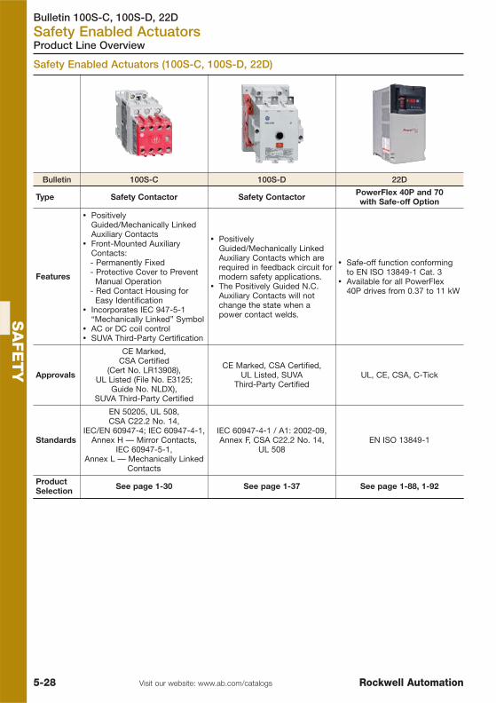
Bulletin 100S-C, 100S-D, 22DSafety Enabled Actuators
5-28 Visit our website: www.ab.com/catalogs Rockwell Automation
SA
FE
TY
Product Line Overview
Bulletin 100S-C 100S-D 22D
Type Safety Contactor Safety Contactor PowerFlex 40P and 70 with Safe-off Option
Features
� PositivelyGuided/Mechanically LinkedAuxiliary Contacts
� Front-Mounted AuxiliaryContacts:- Permanently Fixed- Protective Cover to Prevent
Manual Operation- Red Contact Housing for
Easy Identification� Incorporates IEC 947-5-1
“Mechanically Linked” Symbol� AC or DC coil control� SUVA Third-Party Certification
� PositivelyGuided/Mechanically LinkedAuxiliary Contacts which arerequired in feedback circuit formodern safety applications.
� The Positively Guided N.C.Auxiliary Contacts will notchange the state when apower contact welds.
� Safe-off function conformingto EN ISO 13849-1 Cat. 3
� Available for all PowerFlex40P drives from 0.37 to 11 kW
Approvals
CE Marked,CSA Certified
(Cert No. LR13908),UL Listed (File No. E3125;
Guide No. NLDX),SUVA Third-Party Certified
CE Marked, CSA Certified, UL Listed, SUVA
Third-Party CertifiedUL, CE, CSA, C-Tick
Standards
EN 50205, UL 508, CSA C22.2 No. 14,
IEC/EN 60947-4; IEC 60947-4-1,Annex H — Mirror Contacts,
IEC 60947-5-1,Annex L — Mechanically Linked
Contacts
IEC 60947-4-1 / A1: 2002-09,Annex F, CSA C22.2 No. 14,
UL 508EN ISO 13849-1
ProductSelection See page 1-30 See page 1-37 See page 1-88, 1-92
Safety Enabled Actuators (100S-C, 100S-D, 22D)

Visit our website: www.ab.com/catalogsRockwell Automation
TABLE OF CONTENTS
6-1
Sensors
Phototelectric Sensors 6-2
Inductive Proximity Sensors 6-22
Capacitive Proximity Sensors 6-29
Ultrasonic Sensors 6-31
Condition Sensing Switches 6-33
Industrial RFID Products 6-40
Limit Swiches, see page 5-11

Bulletin 42 (Serie 9000), 43, 44, 45Photoelectric Sensors
6-2 Visit our website: www.ab.com/catalogs Rockwell Automation
SE
NS
OR
S
Product Line Overview
Photoelectric Sensors (42EF RightSight, 42EF LaserSight)
Bulletin 42EF RightSight 42CA 42CM
Type Photoelectric Sensors Cylindrical M18 PhotoelectricSensors
Metal Cylindrical M18Photoelectric Sensors
Features
� Wide selection of sensingmodes
� Popular housing allowsthrough hole mounting aswell as M18 threadedmounting hubs
� Heavy duty and foodapplications
� Clear object detectionmodel available
� Long range laser class Iversion
� Wide selection of sensingmodes
� Popular cylindrical PlasticM18 housing
� Wide selection of sensingmodes
� Popular cylindrical MetalM18 housing
� Heavy duty industrialapplications
SensitivityAdjustment Manual / Teach Manual Manual
Response Time 1…4 ms 0.5 - 1 ms 0.5…2 ms
Sensing Range
Diffuse Reflection 3…500 mm 100 mm, 400 mm, 1000 mm 0…100 / 400 mm
Retroreflective 25 mm…4.5 m 4.8 m, 7.2 m 3 mm…4 m
PolarizedRetroreflective 25 mm…3 m / 15 m 3.8 m 3 mm…3 m
Transmitted Beam 4 m / 8 m / 20 m / 40 m 16 m 3 mm…14 m
Background Supp. 0…50 mm / 100 mm 50 mm, 100 mm 0…50 / 100 mm
Fixed Focus 43 mm ⎯ ⎯
Sharp Cutoff 3…130 mm ⎯ ⎯
Output Mode
Dual NPN and PNPPNP complementary LO/DO
Light On or Dark On (bymodel number)
PNPLight On or Dark On (by
model number)PNP / NPN
Complementary LO & DO
PNPLO and DO selectable
Connection Cable, Micro / M12Connector Micro / M12 Connector Cable, Micro / M12
Connector
Supply Voltage 10…30V DC 10…30V DC 10…30V DC
Enclosure Rating
IP IP 54 IP 67 IP 67
NEMA NEMA 4X, 6P ⎯ ⎯
Special enclosure 1200 psi / 82.7 barwashdown rating
⎯ ⎯
Approvals UL, CSA, CE c-UL, CE c-UL, CE
Product Selection See page 6-7 See page 6-10 See page 6-12
Accessories See page 6-18 See page 6-18 See page 6-18

Bulletin 42 (Serie 9000), 43, 44, 45Photoelectric Sensors
6-3Visit our website: www.ab.com/catalogsRockwell Automation
SE
NS
OR
S
Product Line Overview
Bulletin 42JS
Type 20 mm Miniature Rectangular
Certifications cULus and CE Marked for all applicable directives
Features
� Visible light source offered on all models for ease of alignment� Optional snap-on adaptor enables 18 mm mount and makes sensor
replacement a snap� Patented ASIC design offers linear sensitivity adjustment, stability
indication, and excellent noise immunity� Compact sealed housing and cavity free design to minimize collection of
dust and debris while allowing for easy sensor cleanup� Threaded metal M12 or M8 connector on pigtail� 360° visible LED status indicators� Additional transmitted beam models available with infrared light source for
superior cross talk immunity� Input to disable light source on transmitted beam emitter
Optical
Sensing Modes Polarized retroreflective, diffuse, transmitted beam
Light Source Visible red LED (660 nm) or infrared LED (880 nm)
Adjustments Sensitivity potentiometer or fixed by cat. no.
Electrical
Voltage 10…30V DC
Current Consumption 25 mA max
Sensor Protection Short circuit, overload, false pulse, transient noise, reverse polarity
Outputs
Response Time 1 ms
Output Mode PNP or NPN (by cat. no.)
Output Type Complementary light or dark operate
Output Current 100 mA
Output Leakage Current 10 μA max
Mechanical
Housing Material ABS
Connection Types 2 m cable, 4-pin DC micro (M12) QD, 4-pin pico (M8) QD
Supplied Accessories Mounting hardware (M3 x 25) stainless steel screws
Operating Temperature [C (F)] -20…+60° (-4…+140°)
Operating Environment IP67
Approvals cULus and CE Marked for all applicable directives
Product Selection Page 6-9

Bulletin 42 (Serie 9000), 43, 44, 45Photoelectric Sensors
6-4 Visit our website: www.ab.com/catalogs Rockwell Automation
SE
NS
OR
S
Product Line Overview
Photoelectric Sensors (9000, 9000 LaserSight), Fiber Optics Digital Amplifier (45FVL)
Bulletin 44B 42BT42G
(9000 Series)
Type Background and ForegroundSuppression Sensors
Long Range BackgroundSuppression Sensors
Photoelectric SensorsStandard and Timing
Features
� Adjustable BGS/FGS� Popular square housing
allows through holemounting
� High impact acrylichousing design for ruggedfood industry
� Adjustable BGS� Popular square housing
allows through holemounting
� Long sensing range� Heavy duty industrial
applications� Clear object detection
model available� On/Off Delay, One Shot
Timer
SensitivityAdjustment Manual Manual Manual
Response Time 1 ms 2 ms 2 ms
Sensing Range
Diffuse Reflection ⎯ ⎯ 50.8…4.6 m
Retroreflective ⎯ ⎯ 50.8…9.1 m
PolarizedRetroreflective
⎯ ⎯ 50.8…4.8 m
Transmitted Beam ⎯ ⎯ 25.4…152 m
BackgroundSuppression 20…300 mm 0.2…2 m ⎯
ForegroundSuppression 20…200 mm ⎯ ⎯
Output ModeDual NPN and PNPLight On or Dark On(by model number)
Dual NPN and PNPLO and DO selectable
Dual NPN and PNPLO and DO selectable
Connection Micro / M12 Connector CablePico / M8 Connector
CableMicro / M12 Connector
Supply Voltage 10…30V DC 10…30V DC 10…40V DC
Enclosure Rating
IP IP 67 IP50 IP67
NEMA NEMA 3,4X, 6P, 12, 13 NEMA 1 NEMA 3, 4X, 6P, 12, 13
Special enclosure ⎯ ⎯ 1200 psi / 82.7 barwashdown rating
Approvals UL, c-UL, CE UL, c-UL, CE UL, CSA, CE
Product Selection See page 6-13 See page 6-13 See page 6-14
Accessories See page 6-18 See page 6-18 See page 6-18
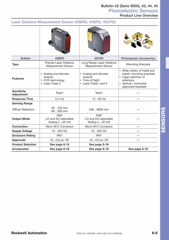
Bulletin 42 (Serie 9000), 43, 44, 45Photoelectric Sensors
6-5Visit our website: www.ab.com/catalogsRockwell Automation
SE
NS
OR
S
Product Line Overview
Laser Distance Measurement Sensor (45BRD, 45BPD, 45CPD)
Bulletin 45BPD 45CPD Photoelectric Accessories
Type Precise Laser DistanceMeasurement Sensor
Long Range Laser DistanceMeasurement Sensor Mounting Brackets
Features
� Analog and discreteoutputs
� CCD technology� Laser Class II
� Analog and discreteoutputs
� Time of flight� Laser Class I and II
� Wide variety of metal andplastic mounting brackets
� Large selection ofreflectors
� Vertical / horizontalalignment brackets
SensitivityAdjustment Teach Teach —
Response Time 0.4 ms 13…30 ms —
Sensing Range
Diffuse Reflection 30…100 mm80…300 mm 200…6000 mm —
Output ModePNP
LO and DO selectableAnalog 4…20 mA
PNPLO and DO selectable
Analog 4…20 mA—
Connection Micro M12 Connector Micro M12 Connector —
Supply Voltage 10…30V DC 10…30V DC —
Enclosure Rating IP67 IP67 —
Approvals UL, cULus, CE UL, cULus, CE —
Product Selection See page 6-15 See page 6-16
Accessories See page 6-18 See page 6-18 See page 6-18

Bulletin 42 (Serie 9000), 43, 44, 45Photoelectric Sensors
6-6 Visit our website: www.ab.com/catalogs Rockwell Automation
SE
NS
OR
S
Product Line Overview
True Color / Light Arrays / Vision Sensor (45CLR, 45PVA, 45AST, 48MS)
Bulletin 45CLR 45PVA 45AST MultiSight™ 48MS
Type ColorSight™ Color /Contrast Sensors
Slim Type PickingSensors Area Arrays Vision Sensor
Features
� Three channel colormatching (3outputs)
� Wiide sensingrange tolerance (±6mm (±0.24 in.))
� Adjustabletolerance for highprecision generalcolor matching
� External teachcapability
� Compact sizeenclosure
� RS--485communicationmodels available
� 35 mm objectresolution
� Robust aluminumenclosure
� Four heights tochoose from
� Highly visible JOBand FAULTindicators
� Crosstalk immunity� Low voltage DC
operation
� Two-dimensionalarray scanningtechnology
� 11…17 mmresolution
� 50, 100, 150 mmscanning heightmodels
� Durable aluminumhousing
� Bracket-freemounting
� Low voltage DCoperation
� Stand-alone visionsensor
� Easy handling andsetup
� Integrated lighting� Multiple virtual
detectors� Ethernet
connection forsetup
� EtherNet/IP™models available
Applications
Precise color matchsensing
Part inspection andsortation
Error proofingBin picking
Small parts assemblyParts ejection sensing —
Sensing Modesand Max. Range
Diffuse 12…32 mm(0.47…1.26 in.)
Transmitted Beam 2m (6.5 ft)
Transmitted beam upto 2.5 m (8 ft) —
Output Type
3 PNP outputs(discrete models)RS485 models: 1
PNP or 1 NPN outputby cat. no.
NPN or PNP 50 mA NPN or PNP 100 mA —
Response Time 1 ms 25…98 ms 4…8 ms 50…100 ms
Connections Micro QD 300V PVC cable withmicro QD 300V PVC cable 2 m —
Operating Voltage 12…30V DC 12…24V DC 12…24V DC —
Enclosure ABS/PMMA,IP67
Aluminum housing,acrylic window,
IP62
Aluminum housing,acrylic window,
IP67
Compact, sturdyindustrial housingwith IP67 rating
Approvals cULus, CE cULus, CE cULus, CE cUL Listed and CEMarked
Product Selection See page 6-16 See page 6-17 See page 6-17 See page 6-17A
Accessories See page 6-18 See page 6-18 See page 6-18 See page 6-17B
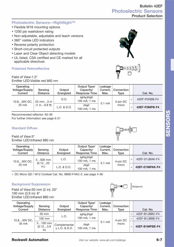
Bulletin 42EFPhotoelectric Sensors
6-7Visit our website: www.ab.com/catalogsRockwell Automation
SE
NS
OR
S
� Flexible M18 mounting options� 1200 psi washdown rating� Non-adjustable, adjustable and teach versions� 360° visible LED indicators� Reverse polarity protection� Short-circuit protected outputs� Laser and Clear Object detecting models� UL listed, CSA certified and CE marked for all
applicable directives
Product Selection
Photoelectric Sensors—RightSight™
Polarized Retroreflective
Field of View:1.5°Emitter LED:Visible red 660 nm
Standard Diffuse
Field of View:5°Emitter LED:Infrared 880 nm
OperatingVoltage/Supply
CurrentSensingDistance
OutputEnergized
Output Type/Capacity/
Response Time
LeakageCurrent,
Max.Connection
Type Cat. No.
10.8…30V DC,35 mA
3…500 mm(0.12…20
in.)
L.O. NPN/PNP100 mA, 1 ms
0.1 mA 4-pin DCmicro
� 42EF-D1JBAK-F4
L.O. & D.O. PNP100 mA, 1 ms � 42EF-D1MPAK-F4
� DC Micro QD / M12 Cordset Cat. No. 889D-F4AC-2, see page 4-36
Background SuppressionBackground
Field of View:50 mm (2 in): 20° 100 mm (3.9 in): 8°Emitter LED:Infrared 880 nm
OperatingVoltage/Supply
CurrentSensingDistance
OutputEnergized
Output Type/Capacity/
Response Time
LeakageCurrent,
Max.Connection
Type Cat. No.
10.8…30V DC,35 mA
25 mm…3 m(1 in…9.8 ft)
D.O. NPN/PNP100 mA, 1 ms
0.1 mA 4-pin DCmicro
� 42EF-P2KBB-F4
L.O. & D.O. PNP100 mA, 1 ms � 42EF-P2MPB-F4
Recommended reflector: 92-39For further information see page 6-21
OperatingVoltage/Supply
CurrentSensingDistance
OutputEnergized
Output Type/Capacity/
Response Time
LeakageCurrent,
Max.Connection
Type Cat. No.
10.8…30V DC,35 mA
50 mmL.O. NPN/PNP
100 mA, 1 ms0.1 mA 4-pin DC
micro
� 42EF-B1JBBC-F4
100 mm � 42EF-B1JBBE-F4
3…100 mm(0.12…3.9
in)
Complementary L.O. & D.O.
PNP100 mA, 1 ms � 42EF-B1MPBE-F4

Bulletin 42EFPhotoelectric Sensors
6-8 Visit our website: www.ab.com/catalogs Rockwell Automation
SE
NS
OR
S
Fixed Focus Diffuse
Background Spot Size:4 mmEmitter LED:Visible red and green by Cat. No.
OperatingVoltage/Supply
CurrentSensingDistance
OutputEnergized
Output Type/Capacity/
Response Time
LeakageCurrent,
Max.Connection
Type Cat. No.
10.8…30V DC,30 mA
—L.O.
NPN & PNP100 mA
1 ms0.1 mA 4-pin DC
micro
�
�42EF-F2JBC-F4
— �
�42EF-F3JBC-F4
� DC Micro QD / M12 Cordset Cat. No. 889D-F4AC-2, see page 4-36� Teachable
Product Selection
Transmitted Beam
Field of View:7°Emitter LED:Infrared 880 nm
OperatingVoltage/Supply
CurrentSensingDistance
OutputEnergized
Output Type/Capacity/
Response Time
LeakageCurrent,
Max.Connection
Type Cat. No.
10.8…30V DC,25 mA
20 m (65.6ft) D.O.
NPN/PNP100 mA
4 ms0.1 mA
4-pin DCmicro
� 42EF-R9KBB-F4
4 m (13.1 ft) � 42EF-R9KBBV-F4
10.8…30V DC,35 mA
Depends onReceiver — � 42EF-E1EZB-F4
Photoelectric Laser Sensors—LaserSight™
� Class 1 visible red laser source� Diffuse, polarized retroreflective and transmitted beam sensing modes� Industry standard housing in popular RightSight package� Flexible M18 mounting or through hole mounting option
SensingMode
OperatingVoltage/SupplyCurrent
SensingDistance(Adjus-table)
OutputEnergized
Output Type/Capacity/
Response Time
LeakageCurrent,
Max.
Connec-tionType Cat. No.
StandardDiffuse
22…26VDC, 40
mA
300 mm(11.8 in.) L.O.
NPN & PNP/100 mA/
1 ms max.0.1 mA 4-pin DC
micro
�
�42EF-D8JBC-F4
� 42EF-D8JBA-F4Polarized
Retroreflective
50 mm…15m (1.96 in.
…49 ft)
D.O.
�
�‡
42EF-P8KBC-F4
Trans.Beam,
Receiver 15 mm…40m (0.59 in.…131 ft)
� 42EF-R7KBB-F4
Trans.Beam,Emitter
� 42EF-E8EZB-F4
‡ Microcube reflector for polarized retroreflective laser sensors 92-118
� DC Micro QD / M12 Cordset Cat. No. 889D-F4AC-2, see page 4-36� TeachableRecommended reflector: 92-118 / For further information see page 6-21

Bulletin 42JSPhotoelectric Sensors
6-9Visit our website: www.ab.com/catalogsRockwell Automation
SE
NS
OR
S
VisiSight™—20 mm Miniature Rectangular
Product Selection
� Visible light source offered on all models for ease of alignment� Optional snap-on adaptor enables 18 mm mount and makes sensor
replacement a snap� Patented ASIC design offers linear sensitivity adjustment, stability indication,
and excellent noise immunity� Compact sealed housing and cavity free design to minimize collection of dust
and debris while allowing for easy sensor cleanup� Threaded metal M12 or M8 connector on pigtail� 360° visible LED status indicators� Additional transmitted beam models available with infrared light source for
superior cross talk immunity� Input to disable light source on transmitted beam emitter
Connector Style Cat. No.
2 m (6.5 ft) DC micro QD cordset � 889D-F4AC-2
2 m (6.5 ft) DC Pico QD cordset � 889P-F4AB-2
� Longer lengths available.
Sensing Mode
OperatingVoltage/
Supply Current
SensingDistance[m (ft)]
Output Type/Capacity
SensitivityAdjustment Cat. No.��
Polarized Retroflective
Objectto be
Sensed
10…30V DC25 mA max.
0.025…3.5(0.08…11.5)
L.O. & D.O.NPN
No adjustment42JS-P2MNB1-F4
L.O. & D.O.PNP 42JS-P2MPB1-F4
L.O. & D.O.NPN Single-turn
potentiometer
42JS-P2MNA2-F4
L.O. & D.O.PNP 42JS-P2MPA2-F4
Standard Diffuse
Objectto be
Sensed
10…30V DC25 mA max.
0.003…0.8(0.01…2.6)
L.O. & D.O.NPN Single-turn
potentiometer
42JS-D2MNA1-F4
L.O. & D.O.PNP 42JS-D2MPA1-F4
Transmitted Beam
10…30V DC25 mA max. 10 (32.8)
NANA No adjustment 42JS-E2EZB1-F4
L.O. & D.O.NPN Single-turn
potentiometer
42JS-R9MNA1-F4
L.O. & D.O.PNP 42JS-R9MPA1-F4
NANA No adjustment 42JS-E1EZB1-F4
L.O. & D.O.NPN Single-turn
potentiometer
42JS-R9MNA2-F4
L.O. & D.O.PNP 42JS-R9MPA2-F4
� The suffix -F4 denotes 4-pin DC micro connection type with 6 in. cable. For 4-pin DC pico QD with 6 in. cablereplace the suffix -F4 with -Y4 (Example: Cat. No. 42JS-P2MPB1-Y4). For 2 m cable without QD replace thesuffix -F4 with -A2 (Example: Cat. No. 42JS-P2MPB1-A2).

Bulletin 42CAPhotoelectric Sensors
6-10 Visit our website: www.ab.com/catalogs Rockwell Automation
SE
NS
OR
S
Product Selection
18 mm Plastic Cylindrical Style
� Complementary light and dark operate outputs (selectable light ordark operate on background suppression models).
� Two LED indicators provide status of power, output, unstableoperation and short-circuit protection.
� Improved 1 ms response time on most models.� Extended range high-speed models with a 0.5 ms response time.� Patented ASIC design offers linear sensitivity adjustment, stabilty
indication and excellent noise immunity.� Flat lens reduces dust collection and improves ease of cleaning.� Visible red LED light source on polarized retroreflective models.� Input to disable light source on transmitted beam emitter for
testing and scanning purposes.
Sensing Mode
OperatingVoltage/SupplyCurrent
SensingDistance [m (ft)]
Output Type/Capacity/
Response TimeSensitivityAdjustment Cat. No. �
Polarized Retroreflective
10…30V DC,25 mA max.
0.002…3.8(0.006…12.5)
L.O. & D.O.PNP/100 mA/
1 ms
Noadjustment 42CA-P2MPB-D4
Retroreflective
10…30V DC,25 mA max.
0.002…4.8(0.006…15.7)
L.O. & D.O.PNP/100 mA/
1 ms
Noadjustment 42CA-U2MPB-D4
0.002…7.2(0.006…23.6)
L.O. & D.O.PNP/100 mA/
0.5 ms
Single turnpotentiometer 42CA-U2MPA-D4
Background Suppression
Background
10…30V DC,30 mA
0.05 (0.16) Selectable L.O. orD.O.
PNP/100 mA/0.5 ms
Noadjustment
� 42CA-B2LPBC-D4
0.1 (0.33) � 42CA-B2LPBE-D4
Standard Diffuse
10…30V DC,30 mA max. 0…0.1 (0…0.33)
L.O. & D.O.PNP/100mA/1 ms
Single turnpotentiometer
� 42CA-D1MPAE-D4
10…30V DC,25 mA max. 0…0.4 (0…1.3) 42CA-D1MPAJ-D4
10…30V DC,30 mA max. 0…1 (0…3.28) 42CA-D1MPAL-D4
Transmitted Beam
10…30V DC,30 mA max.
0.003…16(0.01…52.5)
NA Noadjustment 42CA-E1EZB1-D4
10…30V DC,25 mA max.
L.O. & D.O.PNP/100mA/1 ms
Single turnpotentiometer 42CA-R1MPA1-D4
� Suffix -D4 denotes 4-pin DC micro connection type. For 2 m cable without QD replace suffix -D4 with -A2 (e.g.42CA-P2MPB-A2). All models shown in selection table above are PNP output versions. Replace the eighth digit(P) with N for NPN (example: 42CA-U2MNB-D4 is NPN).
�Refer to www.ab.com/sensors for updated information.

Bulletin 42CAPhotoelectric Sensors
6-11Visit our website: www.ab.com/catalogsRockwell Automation
SE
NS
OR
S
Accessories
Cordsets and Accessories
Description Cat. No.
Cordsets
DC Micro QD Cordset, Straight, 4-pin, 2 m (6.5 ft) 889D-F4AC-2
Right Angle DC Micro QD Cordset, 4-pin, 2 m (6.5 ft) 889D-R4AC-2
Mounting Brackets
Right Angle Mounting Bracket 60-2657
Straight Mounting Bracket 60-2656
Snap-Clamp Mounting Bracket 871A-SCBP18
Right Angle Mounting Bracket 60-2654
Reflectors
Reflector 92-124
32 mm (1.25 in) Diameter Reflector 92-47

Bulletin 42CMPhotoelectric Sensors
6-12 Visit our website: www.ab.com/catalogs Rockwell Automation
SE
NS
OR
S
Product Selection
� M18 industry standard package� Wide selection of sensing modes� Laser models available� 30V DC operation� NPN or PNP outputs� Fast response time� cULus and CE marked for all applicable directives
Metal Cylindrical M18 Photoelectric Sensors
Polarized Retroreflective
Field of View:1.8°Emitter LED:Visible red 660 nm
OperatingVoltage/Supply
CurrentSensingDistance
OutputEnergized
Output Type/Capacity/Response
Time
LeakageCurrent,
Max.Connection
Type Cat. No.
10…30V DC, 30mA
3 mm…3 m(0.12 in.…9.9 ft)
L.O. & D.O.PNP/
100 mA/4 ms
<10μA 4-pin DCmicro
�
42CM-P2MPB-D4
Recommended reflector: 92-39; For further information see page 6-21
Standard Diffuse
Field of View:6.6°Emitter LED:Visible red 660 nm
OperatingVoltage/Supply
CurrentSensingDistance
OutputEnergized
Output Type/Capacity/Response
Time
LeakageCurrent,
Max.Connection
Type Cat. No.
10…30V DC, 30mA
0…400 mm(0…13.6 in.)adjustable
L.O. & D.O.PNP/
100 mA/2 ms
<10μA 4-pin DCmicro � 42CM-D1MPAL-D4
� DC Micro QD / M12 Cordset Cat. No. 889D-F4AC-2, see page 4-36
Transmitted Beam
Field of View:1.6°Emitter LED:Infrared 880 nm
OperatingVoltage/Supply
CurrentSensingDistance
OutputEnergized
Output Type/Capacity/Response
Time
LeakageCurrent,
Max.Connection
Type Cat. No.
10…30V DC, 25mA
3 mm…20 m(0.12 in.…65.6 ft)
NA light source
<10μA 4-pin DCmicro
� 42CM-E1EZB-D4
Selectable L.O.or D.O.
PNP/100 mA/
2 ms� 42CM-R1MPB-D4

Bulletin 44B, 42BTPhotoelectric Sensors
6-13Visit our website: www.ab.com/catalogsRockwell Automation
SE
NS
OR
S
Objectto beSensed
Back-ground
Detection by absence of reflected light from the background.
Foreground Suppression Sensors
Product Selection
Background and Foreground Suppression Sensors� Adjustable background and foreground suppression models� Adjustable sensing range� Power, output, and stability status indicators� Micro QD connection with 90° swivel� Protected from mis-wiring� NPN and PNP outputs� Fast 1 ms response time
Background Suppression Sensors
Detection by presence of reflected light from the target.
Objectto beSensed
Back-ground
OperatingVoltage/SupplyCurrent
SensingDistance
(Adjustable) LED SourceOutput
Energized
Output Type/Capacity/Response
TimeConnection
Type Cat. No.
20…30V DC,22 mA
20…300 mm(0.78…11.8 in.)
Infrared 880nm
Light operate NPN/PNP/100 mA/1 ms
4-pin DCmicro
� 44BSB-1JBA1-D4
Dark Operate � 44BSB-1KBA1-D4
OperatingVoltage/SupplyCurrent
SensingDistance
(Adjustable) LED SourceOutput
Energized
Output Type/Capacity/Response
TimeConnection
Type Cat. No.
20…30V DC,22 mA
20…200 mm(0.78…7.9 in.)
Infrared 880nm
Light Operate NPN/PNP/100 mA/1 ms
4-pin DCmicro
� 44BSN-1JBA1-D4
Dark operate � 44BSN-1KBA1-D4
� DC Micro QD / M12 Cordset Cat. No. 889D-F4AC-2, see page 4-36
Long Range Background Suppression Sensors� Adjustable range settings� Slim flatpack housing design� Highly visible LED indicators� Both NPN and PNP outputs� Short-circuit protected outputs� Fast 2 ms response time
OperatingVoltage/SupplyCurrent
SensingDistance
OutputEnergized
Output Type/Capacity/
Response Time
LeakageCurrent,
Max.Connection
Type Cat. No.Field of View: 1.7°
12…24VDC/30 mA
0.2…1 m(0.66…3.3 ft)
SelectableL.O. or D.O.
NPN & PNP/100 mA/2 ms max 0.1mA 4-pin DC
micro � 42BT-B2LBSL-F4
Field of View: 2.8°12…24V
DC/30 mA0.2…2 m
(0.66…6.4 ft)Selectable
L.O. or D.O.NPN & PNP/
100 mA/2 ms max 0.1mA 4-pin DCmicro � 42BT-B1LBSN-F4
� DC Micro QD / M12 Cordset Cat. No. 889D-F4AC-2, see page 4-36

Bulletin 42G (Serie 9000)Photoelectric Sensors
6-14 Visit our website: www.ab.com/catalogs Rockwell Automation
SE
NS
OR
S
Product Selection
Transmitted Beam
� Harsh duty 30 mm package� Wide selection of sensing modes� Wide selection of operating modes� Both DC and AC/DC operation� Models with teach function� Standard ON/OFF and timing versions� Fast response time� Variety of connection types� UL listed, CSA approved and CE marked for all applicable directives
Photoelectric Sensors Standard and Timing
Field of View:1.5°Emitter LED:Infrared 880 nm
OperatingVoltage/SupplyCurrent
SensingDistance
OutputEnergized
Output Type/Capacity/Response
Time
LeakageCurrent,
Max.Connection
Type Cat. No.
10…40V DC,25 mA
Depends onlight source
ReceiverSelectable L.O.
or D.O.
NPN/PNP/250 mA/
5 ms10 μA 4-pin DC
micro � 42GRR-9000-QD
10…264VAC/DC, 15 mA
0.025…61 m(0.83…200 ft) NA light source — — 4-pin DC
micro � 42GRL-9000-QD
0.025…152 m(0.83…500 ft)
NA LightSource — — 4-pin DC
micro � 42GRL-9040-QD
� DC Micro QD / M12 Cordset Cat. No. 889D-F4AC-2, see page 4-36
Polarized Retroreflective
Field of View:1.5°Emitter LED:Visible red 660 nm
OperatingVoltage/SupplyCurrent Sensing Distance
OutputEnergized
Output Type/Capacity/Response
Time
LeakageCurrent,
Max.Connection
Type Cat. No.
10…40VDC, 30
mA
50.8 mm…4.87 m (2in…6 ft) with 76 mm (3
in.) Reflector
SelectableL.O. or D.O.
NPN & PNP/250 mA/
2 ms10 μA 4-pin DC
micro � 42GRU-9200-QD
Standard Diffuse
Field of View:3.5°Emitter LED:Infrared 880 nm
OperatingVoltage/SupplyCurrent Sensing Distance
OutputEnergized
Output Type/Capacity/Response
Time
LeakageCurrent,
Max.Connection
Type Cat. No.
10…40VDC, 30
mA
50.8 mm…1.52 m (2 in.…5 ft) to White Paper
SelectableL.O. or D.O.
NPN & PNP/100 mA/
2 ms10 μA 4-pin DC
micro
� 42GLP-9000-QD
�
�42GSP-9000-QD
� Teachable

Bulletin 45BPDPhotoelectric Sensors
6-15Visit our website: www.ab.com/catalogsRockwell Automation
SE
NS
OR
S
Precise Laser Distance Measurement Sensor� Noncontact measurement� Visible red laser, Class 2� Analog and discrete outputs� Easy set-up using Teach-in buttons� Scalable analog output (4…20 mA)� Configurable discrete output (N.O./N.C.)� IP 67 enclosure� 270° rotatable connector� Set point adjustment via pushbuttons� Self-contained sensor� Laser-disable control� Teach-in lock out� Averaging and speed mode
Sensing Range [mm (in.)] Measuring Range—mm (in) Spot Size [mm (in.)] Cat. No.
30…100 (1.18…3.93) 70 (2.75) 1.5 x 3/1.5 x 3.25 (0.06 x0.12/0.06 x 0.13) � 45BPD-8LTB1-D5
80…300 (3.14…11.8) 220 (8.66) 1.5 x 3.5/2.0 x 4.5 (0.06 x0.14/0.08 x 0.18) � 45BPD-8LTB2-D5
� DC Micro QD / M12 Cordset Cat. No. 889D-F5AC-2, see page 4-36
Product Selection

Bulletin 45CPD, 45CLRPhotoelectric Sensors
6-16 Visit our website: www.ab.com/catalogs Rockwell Automation
SE
NS
OR
S
Product Selection
Long Range Laser Distance Measurement Sensor
Sensing Range [mm (in.)] Measuring Range—mm (in) Spot Size [mm (in.)] Cat. No.
200…6000 (7.87…236.22) 5800 (228.35) 4 x 7 @ 2 m (0.16 x 0.28 @6.56 ft) � 45CPD-8LTB1-D5
� DC Micro QD / M12 Cordset Cat. No. 889D-F5AC-2, see page 4-36
� Eye Safe Class 1 laser for operation� Visible red Class 2 laser for set-up� 6 m sensing range� 2 discrete outputs (PNP) and analog output
(4…20 mA)� Easy set-up using teach-in buttons� IP 67 enclosure� Self-contained sensor
45CLR ColorSight™ Color / Contrast Sensors� Wide sensing range tolerance� Three channel color matching (three outputs)� Gating input (also known as inhibiting input)� Adjustable tolerance for high precision to general color matching� Pulse stretching capability (50 ms off delay)� Teach colors via pushbuttons� External teach capability (one output)� Teach button lockout� 270° rotatable connector� Compact size IP67 enclosure
Sensing Range[mm (in.)]
Sensing RangeTolerance � Spot Size [mm (in.)] Output Type Cat. No.
12…32 (0.47…1.26) ±6 mm (0.24 in.) 4 (0.16) @ 22 (0.87) 3 PNP � 45CLR-5JPC1-D8
12…32 (0.47…1.26) ±6 mm (0.24 in.) 4 (0.16) @ 22 (0.87) RS-485, 1 PNP � 45CLR-5LPS1-D8
� For medium color tolerance settings within a specified range.� Items preferred stocked
Cordsets and Accessories
Description Cat. No.
DC Micro Style QD Cordset, 8-Pin 889D-F8AB-2
Mounting bracket for 45BPD, 45BRD, 45CLR 45BPD-BKT1
Mounting bracket for 45BPD, 45BRD, 45CLR 45BPD-BKT2
Communications Cable (RS-485) for MicroLogix 1763-NC01
MicroLogix Advanced Interface Converter Module 1761-NET-AIC

Bulletin 45PVA, 45ASTPhotoelectric Sensors
6-17Visit our website: www.ab.com/catalogsRockwell Automation
SE
NS
OR
S
Product Selection
45PVA Slim Type Picking Sensors� Robust metal enclosure with super slim 13 mm profile� Large highly-visible job indicator lights� Optional red fault light indicator to notify operator of incorrect
component selection� Dip switch selectable lighting operation for job lights� NPN or PNP dip switch selectable output reduces inventory� Two frequency dip switch selectable cross talk protection� Different sizes are available for different component racks. Transmitted
beam models are available in four sizes (100 mm (4 in), 225 mm (9 in),300 mm (12 in), and 375 mm (15 in)). Retroreflective/diffuse models areavailable in two sizes (100 mm (4 in) and 225 mm (9 in)).
45AST Area Arrays� Introduces two-dimensional array scanning technology� PNP or NPN output� Minimum object resolution from 11…17 mm (0.43…0.66 in)� Sensing ranges up to 2.5 m (8.2 ft)� IP 67 rated housing� CE marked for all applicable directives� Easy bracket-free mounting� Highly visible alignment LEDs
Sensing Mode Light Source
Numberof Optical
AxesDetection
Width
CurrentConsum-
ption Response Time Cat. No.
Transmitted-Beam
Infrared LED,Wave–length
880 nm
5 100 mm(3.93 in) 130 mA
Standard: Light on: 35ms/Dark on: 25 ms
Interference Protection: Lighton: 45 ms/Dark on: 28 ms
45PVA-1LEB1-F4
10 225 mm(8.85 in) 140 mA
Standard: Light on: 68ms/Dark on: 42 ms
Interference Protection: Lighton: 84 ms/Dark on: 52 ms
45PVA-1LEB2-F4
13 300 mm(11.8 in) 150 mA
Standard: Light on: 70ms/Dark on: 42 ms
Interference Protection: Lighton: 88 ms/Dark on: 54 ms
45PVA-1LEB3-F4
16 375 mm(14.7 in) 155 mA
Standard: Light on: 94ms/Dark on: 58 ms
Interference Protection: Lighton: 116 ms/Dark on: 72 ms
45PVA-1LEB4-F4
CurrentConsumption
SensingRange [m
(ft)]
Number ofOpticalAxes
ResponseTime
ResolutionDiameter[mm (in.)]
SensingHeight
[mm (in.)]OutputType Cat. No.
Trans. 70 mAmax; Rec’r 65mA max
0.5…2(1.6…6.5) 5 4 ms max 15 (0.59) 50 (2) PNP � 45AST-1JPB1-A2
Trans. 80 mAmax; Rec’r110 mA max
0.15…0.80(0.5…2.6)
10 8 ms max
11 (0.43)100 (4)
PNP � 45AST-1JPB2-A2
0.5…2.5(1.6…8.2) 13 (0.51) PNP � 45AST-1JPB3-A2
0.15…0.80(0.5…2.6) 17 (0.66) 150 (6) PNP � 45AST-1JPB4-A2
� Items preferred stocked

Bulletin 48MSPhotoelectric Sensors
6-17A Visit our website: www.ab.com/catalogs Rockwell Automation
SE
NS
OR
S
Product Selection
48MS MultiSight™ Vision Sensor
� Stand-alone vision sensor� Easy handling and setup� Compact, sturdy industrial housing with IP 67 rating � Integrated lighting� Adjustable focus from 20 mm to infinity� Short evaluation time (50…100 ms)� Three evaluation methods: pattern matching, brightness, and
contrast� 10 virtual detectors� Individual virtual detectors can be logically linked or grouped
for evaluation of different objects with several characteristicsfor inspection
� Ethernet connection for setup
Operating Voltage/Supply Current
Focal Lengthof Lens
Field of View[@200 mm] EtherNet / IP Cat. No.
24V DC ±10%,≤200 mA
12 mm X = 60 mmY = 40 mm
No48MS-SE1PF2-M2
6 mm X = 150 mmY = 100 mm � 48MS-SE1PF1-M2
12 mm X = 60 mmY = 40 mm
Yes48MS-SN1PF2-M2
6 mm X = 150 mmY = 100 mm � 48MS-SN1PF1-M2
� The 6 mm lens models typically require external lighting because the integrated lighting does not illuminate theentire field of view, i.e., the edges of the image are dark.

Bulletin 48MSPhotoelectric Sensors
6-17BVisit our website: www.ab.com/catalogsRockwell Automation
SE
NS
OR
S
Accessories
Accessories
Description Cat. No.
Angle Bracket 48MS-BKTANG
Rod Bracket 48MS-BKTROD
Mounting Rod 200 mm 48MS-ROD200
Mounting Rod 400 mm 48MS-ROD400
Rod Clamp 48MS-CLAMP
Mounting Plate 48MS-MTPLATE
MultiSight Cordset, 2 m 48MS-CS2
MultiSight Cordset, 5 m 48MS-CS-5
MultiSight Cordset, 10 m 48MS-CS-10
MultiSight Cordset Right Angle, 2 m 48MS-CSRT-2
MultiSight Cordset Right Angle, 5 m 48MS-CSRT-5
Ethernet Crossover Patchcord 3 m, M12, 8-pin/RJ45 48MS-ECSCROSS-3
Ethernet Patchcord 3 m, M12, 8-pin/RJ45 48MS-ECS-3
RJ45 Connector 48MS-RJ45CONN
Ethernet Crossover Cable RJ45/RJ45 48MS-ECROSS
Area Light—White Light 48MS-ALWH
Ring Light—White Light 48MS-RLWH
Lighting Cable 48MS-LCS
Lighting Cable Right Angle 48MS-LCRT
MultiSight Test Box 48MS-TESTBOX

Bulletin 42 (Serie 9000), 44, 45Photoelectric Sensors
6-18 Visit our website: www.ab.com/catalogs Rockwell Automation
SE
NS
OR
S
Mounting Brackets
Description Dimensions—mm (in) Height Cat. No.
Swivel/Tilt Bracket Allows ±10°Vertical and 360° RotationAdjustment
10° Adjustment inEach Direction
28.6(1.125)
7.95(0.31)
50.08(2.0)
57.15(2.25)
—
60-2649
60-2439
Right angle mounting bracketallows 30° horizontal adjustment.Used for RightSight, MiniSight,42CA, 42CB, and 42CM stylesensors.
35.8(1.41)
42.4(1.67)
35.8(1.41)
60-2657
Right angle mounting bracketpermits a 360° rotationadjustment. Used for Series 9000style sensors.
60.2(2.37)
67.3(2.65)
71.1(2.80)
60-2421
Photoelectric sensor mountingbracket with vertical heightadjustment for any swivel/tiltbracket (not included).
H
101.6(4.0)
152.4(6.0)
22.2(1.88)
101.6 (4.0) 60-2721
152.4 (6.0) 60-2722
203.2 (8.0) 60-2723
254 (10) 60-2724
Reflector mounting bracket withvertical height adjustment for 3 in.diameter (or smaller) center-mounted reflector.
H
101.6(4.0)
152.4(6.0)
22.2(1.88)
203.2 (8.0) 60-2718
254 (10) 60-2719
304.8 (12.0) 60-2720
Accessories

Bulletin 42 (Serie 9000), 44, 45Photoelectric Sensors
6-19Visit our website: www.ab.com/catalogsRockwell Automation
SE
NS
OR
S
Accessories
Mounting Brackets
Description Dimensions—mm (in) Cat. No.
Mounting Brackets (2 Brackets, included)
Mounting Bracket. Used for PartsVerification Array 45PVA
11 (0.43)
6 (0.23)
Ø 4.6(0.18)
Ø 4.6(0.18)
10(0.39)
10(0.39)
20(0.78)
40 (1.57)
16 (0.63)
18 (0.7)
2 (0.07)
23(0.91)
60-2773
Optional Mounting Brackets (not included with sensor)
Mounting Bracket. Used for PartsVerification Array 45PVA
Ø 26.9(1.06)
66(2.60)
4.4 (0.17)
20.1(0.79)
18.8 (0.74)
7.4 (0.29)
18.0(0.71)
7.6 (0.30)
17.0 (0.67)
34.0 (1.34)
60-2779
Mounting Bracket. Used for PartsVerification Array 45PVA
51.8 (2.04)
2 x M5 x 0.8
16.0 (0.63)
18.0(0.71)
7.4 (0.29)
18.0 (0.71)
9.2 (0.36)
7.0 (0.27)
68.3 (2.69)
Ø 28.0(1.10) 2.5
(0.10)
Ø 5.2 (0.20)
2 x 16.0 (0.63)
28 (1.1)
4 x M4 x 0.7
32.0 (1.26)
60-2772
Mounting Bracket. Used for Backgroundand Foreground Suppression 44B. 60-BKTL-SS

Bulletin 42 (Serie 9000), 44, 45Photoelectric Sensors
6-20 Visit our website: www.ab.com/catalogs Rockwell Automation
SE
NS
OR
S
Mounting Brackets
Description Dimensions—mm (in) Cat. No.
Dovetail Bracket. Used forBackground and ForegroundSuppression Sensors 44B
44B-BKT
Mounting bracket for 45BPD,45BRD, 45CLR
4.3 (0.169)
4.2(0.165)
10.5 (0.41)
22 (0.86)
24°
4.3
(0.1
69)
10.5(0.41)
50°
30(1.18)
50.97(2.0)
4.3(0.169)
48.5 (1.9)
45BPD-BKT1
Mounting bracket for 45BPD,45BRD, 45CLR
2(0.07)
21.2(0.83)
13.9(0.54)
58(2.28)
4.3(0.169)
24°
4.3 (0.169)
14.85 (0.58)
17(0.66)
23.8(0.93)
7 x M4
38.2 (1.5)
8.5(0.33)
65 (2.55)
45BPD-BKT2
Mounting bracket for 45CPD
Ø 3.1 (0.12)
28(1.1)
11 (0.43)
50 (1.96)
4 (0.15)
45°
5.2 (0.2)
14 (0.55)
18 (0.7)
25 (0.98)
R30
32 (1.25)
0.06(0.002)
140.5 (5.53)
5.2 (0.2)
90.5 (3.56)
53 (2.08)
Ø 3.1(0.12)
R81.5
20°
5.2 (0.2)3(0.11)
4 (0.15)
45(1.77)
45CPD-BKT1
Accessories
Protective Metal Brackets (Galvanized Steel)
L1mm (in)
L2mm (in) Dimensions—mm (in)
Cat. No.(1 bracket)
Cat. No.(2 brackets)
130 (5.11) 148.36 (5.84)
L1
4 x R 5.08 (0.20)
7.01 (0.27) 16.3 (0.64)
17.5 (0.689)
R 3.05(0.12)
12.34 (0.486)
8.99(0.354) Ref.
2 x 18 (0.709)
2 x R 2.03 (0.08)
Ø 4 x 4.97 (0.196)
10.0(0.39)
111.3 (4.38)68.3 (2.69)
51.3 (2.02)
27.3 (1.07)
L2
10.0(0.39)
9.5 (0.37)
13.99 (0.55)
35°
R08 Ref. External RadiiR.02 Ref.
Internal Radii 32.5 (1.28)
60-2785-1 60-2775-1
254 (10.03) 273.35 (10.76) 60-2786-1 60-2776-1
330 (12.99) 348.36 (13.71) NA 60-2777-1
405 (15.94) 423.34 (196.6) NA 60-2778-1

Bulletin 42 (Serie 9000), 44, 45Photoelectric Sensors
6-21Visit our website: www.ab.com/catalogsRockwell Automation
SE
NS
OR
S
Reflectors
Accessories
DescriptionDimension—
mm (in)CubeStyle Mounting
Temperature—C (F) Cat. No.
Diameter76 mm (3 in.)Diameter with CenterMount Hole
Diameter76.2 (3)
CornerCube
Thru-Hole
≤65 ° (150 °)
92-39
Thru-Hole 92-89
32 mm (1.25 in)diameter
Diameter31.75 (1.25)
Adhesive 92-47
M5 Screw 92-105
Snap-Fit 92-106
Microcube reflectorfor polarizedretroreflective lasersensors
Diameter51 x 61 (2 x
2.5)
MicroCube Thru-hole ≤65 ° (150 °) 92-118
Reflector, rectangularwith mounting tabsand bracket. Rightangle bracket andadhesive tape.
23 x 42.5(0.91 x 1.67)
CornerCube Thru-Hole ≤55° (130°) 92-93
Reflector, rectangularwith mounting tabs
18.5 x 120(0.73 x 4.72)
CornerCube Thru-Hole ≤65° (150°) 92-107
Reflector, squarewith mounting tabs
100 x 100(4 x 4)
CornerCube Thru-hole ≤65 ° (150 °) 92-108
Reflector, rectangularwith mounting tabs
19 x 72.5(0.75 x 2.85)
CornerCube Thru-Hole ≤55° (130°)
92-111
23.5 x 55(0.924 x 2.17) 92-112
40.5 x 60(1.6 x 2.36)
92-113
92-117
Reflective Tapes (included with retroreflective/diffuse models)
L
W
Dimensions
For Use With Cat. No.Width [mm (in.)] Length [mm (in.)]
50 (2) 120 (4.7) 45PVA-2LEA1-F4 92-122
50 (2) 245 (9.6) 45PVA-2LEA2-F4 92-123

Bulletin 872C, 871TM, 871FM, 871C, 871PInductive Proximity Sensors
6-22 Visit our website: www.ab.com/catalogs Rockwell Automation
SE
NS
OR
S
Product Line Overview
Proximity Sensors (872C, 871TM, 871FM)
Bulletin 872C 871TM 871PInductive Proximity
Accessories
Type Proximity SensorsWorldProx Inductive
Proximity SensorsStainless Steel
Inductive
VersaCube InductiveSensors Mounting Brackets
Features
� 360° visible LED� Nickel-Plated Brass
or Plastic Barrel� Standard and
extended sensingmodels
� Full mechanical sealwith leak-proof frontend
� Ideal for heavy duty,metalworking andfood applications
� High enclosure,cleaning resist andwashdown rating(82,7 bar / 1200psi)
� Standard andextended sensingmodels
Long distance cubetypeRugged burn andweld-slag resistandWeld field immuneEqual sensing(factor1) modelsavailable
Wide variety of metaland plastic mountingbracketsRight angle, clampand spring loadedbrackets
Barrel Size Diameter 6.5 mm,M8, M12, M18, M30 M8, M12, M18, M30 Cube 40 x 40 mm ⎯
Sensing Range
Standard SensingRange 2 mm…15 mm 2 mm…15 mm 20 mm…40 mm ⎯
Extended SensingRange 2 mm…20 mm 2 mm…40 mm ⎯ ⎯
Output Mode
PNPNormally Open
ShieldedNonshielded3-wire DC2-wire AC
PNPNormally Open
ShieldedNonshielded3-wire DC2-wire AC
Normally OpenShielded
Nonshielded3-wire DC
⎯
ConnectionCable
Micro / M12Connector
CableMicro / M12Connector
Micro / M12Connector
⎯
Supply Voltage 10…30V DC20…250V AC
10…30V DC20…250V AC 10…30V DC ⎯
Enclosure Rating
IP IP 67 IP 67 IP 67 ⎯
NEMA NEMA1,2,3,4,6P,12,13
NEMA1,2,3,3R,4,4X,6,
6P,12,13
NEMA1,2,3,4,6P,12,13
⎯
Special enclosure ⎯ 1200 psi / 82.7 barwashdown rating
1200 psi / 82.7 barwashdown rating
⎯
Approvals UL, c-UL, CE UL, CSA, CE UL, c-UL, CE ⎯
ProductSelection See page 6-23 See page 6-25 See page 6-26
Accessories See page 6-26 See page 6-26 See page 6-26 See page 6-26

Bulletin 872CInductive Proximity Sensors
6-23Visit our website: www.ab.com/catalogsRockwell Automation
SE
NS
OR
S
Product Selection
Proximity Sensors WorldProx Inductive
3-Wire DC Standard and Short Barrel
� 3-wire operation� 3-conductor, 3- or 4-wire connection� 10…30V DC� Normally-open or normally-closed output� Short circuit, overload, false pulse, reverse polarity,
and transient noise protection� UL listed, cUL listed and CE marked for all applicable
directives
Standard Barrel
Short Barrel
ConnectionType
BarrelDiameter
[mm]Nominal Sensing
Distance [mm (in.)] ShieldedOutput
Configuration
SwitchingFrequency
(Hz) Cat. No.
Cable Style
M6.5 2 (0.08) Yes N.O. PNP 2000 872C-MM1NP7-E2
M8 2 (0.08) Yes N.O. PNP 2500 872C-D2NP8-E2
M123 (0.12) Yes N.O. PNP 1300 872C-D3NP12-E2
4 (0.16) No N.O. PNP 1300 872C-D4NP12-E2
M18 5 (0.20) Yes N.O. PNP 1500 872C-D5NP18-E2
Pico QD Style M6.5 2 (0.08) Yes N.O. PNP 2000 872C-MM1NP7-P3
Micro QDStyle
M82 (0.08) Yes N.O. PNP 2500 � 872C-D2NP8-D4
3 (0.12) No N.O. PNP 2500 � 872C-D3NP8-D4
M123 (0.12) Yes N.O. PNP 1300 � 872C-D3NP12-D4
4 (0.16) No N.O. PNP 1300 � 872C-D4NP12-D4
M185 (0.2) Yes N.O. PNP 1500 � 872C-D5NP18-D4
8 (0.31) No N.O. PNP 1500 � 872C-D8NP18-D4
ConnectionType
BarrelDiameter
[mm]Nominal Sensing
Distance [mm (in.)] ShieldedOutput
Configuration
SwitchingFrequency
(Hz) Cat. No.
Cable style
M123 (0.12) Yes N.O. PNP 1300 � 872C-DH3NP12-E2
4 (0.16) No N.O. PNP 1300 � 872C-DH4NP12-E2
M185 (0.2) Yes N.O. PNP 1500 � 872C-DH5NP18-E2
8 (0.32) No N.O. PNP 1500 � 872C-DH8NP18-E2
M3010 (0.39) Yes N.O. PNP 1000 � 872C-DH10NP30-E2
15 (0.59) No N.O. PNP 1000 � 872C-DH15NP30-E2
Micro QD style
M123 (0.12) Yes N.O. PNP 1300 � 872C-DH3NP12-D4
4 (0.16) No N.O. PNP 1300 � 872C-DH4NP12-D4
M185 (0.20) Yes N.O. PNP 1500 � 872C-DH5NP18-D4
8 (0.31) No N.O. PNP 1500 � 872C-DH8NP18-D4
M3010 (0.39) Yes N.O. PNP 1000 � 872C-DH10NP30-D4
15 (0.59) No N.O. PNP 1000 � 872C-DH15NP30-D4
� DC Micro QD / M12 Cordset Cat. No. 889D-F4AC-2, see page 4-36

Bulletin 872CInductive Proximity Sensors
6-24 Visit our website: www.ab.com/catalogs Rockwell Automation
SE
NS
OR
S
Product Selection
3-Wire DC Extended Sensing� 3-wire operation� 3-conductor, 4-wire connection� 10…30V DC� Normally-open or normally-closed output� Short circuit, overload, false pulse, reverse polarity, and transient
noise protection� UL and cUL recognized and CE marked for all applicable directives
ConnectionType
BarrelDiameter
[mm]Nominal Sensing
Distance [mm (in.)] ShieldedOutput
Configuration
SwitchingFrequency
(Hz) Cat. No.
Cable StyleM12
4 (0.16) Yes N.O. PNP 900 872C-M4NP12-A2
8 (0.31) No N.O. PNP 900 872C-N8NP12-A2
M188 (0.31) Yes N.O. PNP 300 872C-M8NP18-A212 (0.47) No N.O. PNP 300 872C-N12NP18-A2
Pico QD Style M83 (0.12) Yes N.O. NPN 700 � 872C-M3NP8-P34 (0.16) No N.O. NPN 700 � 872C-N4NP8-P3
Micro QD style
M83 (0.12) Yes N.O. PNP 2500 � 872C-M3NP8-D44 (0.16) No N.O. PNP 2500 � 872C-N4NP8-D4
M124 (0.16) Yes N.O. PNP 1300 � 872C-M4NP12-D48 (0.31) No N.O. PNP 1300 � 872C-N8NP12-D4
M188 (0.31) Yes N.O. PNP 1500 � 872C-M8NP18-D4
12 (0.47) No N.O. PNP 1500 � 872C-N12NP18-D4
M3015 (0.59) Yes N.O. PNP 1000 � 872C-M15NP30-D420 (0.79) No N.O. PNP 1000 � 872C-N20NP30-D4
� DC Micro QD / M12 Cordset Cat. No. 889D-F4AC-2, see page 4-36
2-Wire AC
� 2-wire operation� 3-conductor or 3-wire connection� 20…250V AC (20…240V AC for 8 mm)� Normally-open or normally-closed output� False pulse and transient noise protection� Extended sensing distance on M18 unshielded models� CE marked for all applicable directives
ConnectionType
BarrelDiameter
[mm]
NominalSensingDistance[mm (in.)] Shielded
OutputConfiguration
SwitchingFrequency
(Hz) Cat. No.
Cable Style
M8 1.5 (0.06) Yes
N.O.
25 872C-A1N8-A2
M122 (0.08) Yes
15
872C-A2N12-A24 (0.16) No 872C-A4N12-A2
M185 (0.20) Yes 872C-A5N18-A210 (0.39) No 872C-A10N18-A2
M30 15 (0.59) No 872C-A15N30-A2
Micro QDStyle
M122 (0.08) Yes � 872C-A2N12-R3
4 (0.16) No � 872C-A4N12-R3
M185 (0.20) Yes � 872C-A5N18-R3
10 (0.39) No � 872C-A10N18-R3
�AC Micro QD / M12 ordset Cat. No. 889R-F3ECA-2, see page 4-38

Bulletin 871TMInductive Proximity Sensors
6-25Visit our website: www.ab.com/catalogsRockwell Automation
SE
NS
OR
S
Product Selection
Proximity Sensors Stainless Steel Inductive
3-Wire DC
� 3-wire operation� 3-conductor or 4-wire connection� 10…30V DC� Short circuit, overload, false pulse, reverse polarity,
and transient noise protection� Normally-open or normally-closed output� UL listed, CSA certified and CE marked for all
applicable directives
ConnectionType
BarrelDiameter
[mm]Nominal Sensing
Distance [mm (in.)] ShieldedOutput
Configuration
SwitchingFrequency
(Hz) Cat. No.
ToughLink™ cable M18
5 (0.20) Yes N.O. PNP 60 871TM-DH5NP18-H2
8 (0.31) No N.O. PNP 40 871TM-DH8NP18-H2
Micro QDstyle
M122 (0.08) Yes N.O. PNP 75 � 871TM-DH2NP12-D4
4 (0.16) No N.O. PNP 70 � 871TM-DH4NP12-D4
M185 (0.20) Yes N.O. PNP 60 � 871TM-DH5NP18-D4
8 (0.31) No N.O. PNP 40 � 871TM-DH8NP18-D4
3-Wire DC Extended Range
� 3-wire operation� 3-conductor or 4-wire connection� 10…30V DC� Short circuit, overload, false pulse, reverse
polarity, and transient noise protection� Normally-open or normally-closed output� Equal sensing for both steel and aluminum� CE marked for all applicable directives
ConnectionType
BarrelDiameter
[mm]Nominal Sensing
Distance [mm (in.)] ShieldedOutput
Configuration
SwitchingFrequency
(Hz) Cat. No.
Micro QDStyle M8
3 (0.12) Yes N.O. PNP 700 � 871TM-M3NP8-D4
6 (0.23) Yes N.O. PNP 700 � 871TM-N6NP8-P3
Micro QDStyle
M83 (0.12) Yes N.O. PNP 700 � 871TM-M3NP8-D4
6 (0.23) Yes N.O. PNP 700 � 871TM-N6NP8-D4
M126 (0.23) Yes N.O. PNP 400 � 871TM-M6NP12-D4
10 (0.39) No N.O. PNP 400 � 871TM-N10NP12-D4
M1810 (0.39) Yes N.O. PNP 200 � 871TM-M10NP18-D4
20 (0.79) No N.O. PNP 200 � 871TM-N20NP18-D4
M3020 (0.79) Yes N.O. PNP 80 � 871TM-M20NP30-D4
40 (1.57) No N.O. PNP 80 � 871TM-N40NP30-D4
� DC Micro QD / M12 Cordset Cat. No. 889D-F4AC-2, see page 4-36

Bulletin 871PInductive Proximity Sensors
6-26 Visit our website: www.ab.com/catalogs Rockwell Automation
SE
NS
OR
S
VersaCube Inductive Sensors
� New rugged housing� Weld-field immune models� Burn and weld-slag resistant body on weld-field immune models� Convenient mounting base� 3-wire operation� 4-pin connection� 10…60V DC� Normally-open or normally-closed output� Short circuit, overload, false pulse, reverse polarity, and transient
noise protection� UL listed, cUL certified and CE marked for all applicable
directives
3-Wire DC VersaCube™
Product Selection
ConnectionType
HeadSize
Weld FieldImmune
NominalSensing
Distance [mm(in.)] Shielded
OutputConfiguration
SwitchingFrequency
(Hz) Cat. No.
Micro QDStyle
40mm No
20 (0.79) Yes N.O. PNP 100 � 871P-D20NP40-D4
40 (1.57) No N.O. PNP 100 � 871P-D40NP40-D4
� DC Micro QD / M12 Cordset Cat. No. 889D-F4AC-2, see page 4-36
Description Dimensions—mm (in) Cat. No.
The swivel/tilt mounting bracket provides both axial and10° tilt adjustment for our 18mm and 30mm tubular-styleproducts.
12.7(0.5)
66.04(2.6)
50.8(2.0)
28.6(1.125)
20.32(0.8)
27.94(1.1)
29.12(1.15)
18 mm and 30 mmInside Thread
60-2649
60-2439
Accessories
Mounting Brackets for Tubular Proximity Sensors—Swivel/Tilt Style

Bulletin 872C, 871TM, 871FM, 871C, 871PInductive Proximity Sensors
6-27Visit our website: www.ab.com/catalogsRockwell Automation
SE
NS
OR
S
Proximity Tube Diameter[mm (in.)] Dimensions—mm (in) Material Cat. No.
8 (0.31)1.78(0.07)
8.74(0.34)
9.35(0.37)
8.74(0.34)
25.4(1.0)
5.54(0.21)
15.9(0.625)
31.8(1.25)
11.9(0.46)
7.14(0.28)
31.8 (1.25)
7.92(0.31)
Zinc–PlatedSteel 871A-BRN8
Stainless Steel 871A-BRS8
12 (0.47)1.78(0.07)
12.7(0.50)
13.9(0.55)
38.1(1.50)
5.54(0.21)
19.1(0.75)
38.1(1.50)
14.3(0.56)
7.92(0.31)
34.8 (1.37)
9.53(0.37)
12.7(0.5)
Zinc–platedsteel 871A-BRN12
Stainless Steel 871A-BRS12
18 (0.71)1.78(0.07)
19.1(0.75)
19.1(0.75)
50.8(2.0)
5.54(0.21)
25.4(1.0)
44.5(1.75)
14.3(0.56)
7.92(0.31)
34.8 (1.37)
9.53(0.37)
15.9(0.62)
Zinc–platedsteel 871A-BRN18
Stainless Steel 871A-BRS18
For use with the 871A-BXN12 or 871A-BXS12Spring Return Brackets.
1.78(0.07)
22.2(0.87)
17.4(0.68)
50.8(2.0)
5.54(0.21)
25.4(1.0)
44.5(1.75)
14.3(0.56)
7.92(0.31)
34.8 (1.37)
9.53(0.37)
15.9(0.62)
Zinc–PlatedSteel 871A-BRN22
Stainless Steel 871A-BRS22
30 (01.18)2.16(0.08)
30.5(1.18)
23.0(0.90)
63.5(2.5)
7.14(0.28)
34.8(1.37)
57.2(2.25)
20.6(0.81)
10.3(0.4)
44.5 (1.75)
11.2(0.44)
19.1(0.75)
Zinc–PlatedSteel 871A-BRN30
Stainless Steel 871A-BRS30
For use with the 871A-BXN30 or 871A-BXS30Spring Return Brackets. 3.05
(0.12)
47.5(1.87)
38.1(1.5)
88.9(3.5)
7.14(0.28)
38.1(1.5)
63.5(2.5)
25.4(1.0)
12.7(0.5)
50.8 (2.0)
12.7(0.5)
19.1(0.75)
Zinc–PlatedSteel 871A-BRN47
Stainless Steel 871A-BRS47
Mounting Brackets for Tubular Proximity Sensors—Right Angle Style
Accessories

Bulletin 872C, 871TM, 871FM, 871C, 871PInductive Proximity Sensors
6-28 Visit our website: www.ab.com/catalogs Rockwell Automation
SE
NS
OR
S
Accessories
Kit includes:� (1) Threaded mounting bracket� (1) Through-hole mounting bracket� (2) 10–32 x 1 mounting screw� (2) 10–32 x 1 mounting screw� (1) Ground terminal lug� (1) Green color-coded binding screw
Description Dimensions—mm (in) Cat. No.The mounting kit for VersaCube sensorsprovides additional mounting flexibility to871P VersaCube style sensors. This kitincludes an accessory mounting bracket thatallows the VersaCube to bolt in place ofexisting 871P rectangular and similarcompetitive sensors. Appropriately sizedmounting screws are also supplied.Additionally a ground lug terminal and greencolor-coded binding screw are provided forgrounding the VersaCube sensor in the eventthat the unit is not mounted to a groundedmetal frame.
40(1.58)
30(1.18)
17(0.67)
14.2(0.56)
20(0.78)
11.8(0.46)
24.9(098)
871A-PKIT
Stainless Steel Mounting Hardwareand Chemical Resistant Materialfor Harsh Environment
SensorDiameter—
mm
Dimensions—mm (inches)
Cat. No.C D G7.0
(0.28)
1.5(0.06) Ø 2.4
(0.09)
G 12.0(0.47)
4 ⎯ ⎯ 4(0.16) 871A-BP4
5 ⎯ ⎯ 5(0.20) 871A-BP5
6.5 ⎯ ⎯ 6.5(0.26) 871A-BP7
CDia. ofProximitySensor
Bracket
D
8 8.0(0.31) 18.3
(0.72)⎯
871A-BP8
12 12.0(0.47) 871A-BP12
18 18.0(0.71)
29.4(1.16)
⎯ 871A-BP18
30 30.0(1.18)
48.4(1.91)
⎯ 871A-BP30
34 34.0(1.34)
48.3(1.90)
⎯ 871A-BP34
Snap-Clamp Brackets
Barrel Diameter [mm] Material Cat. No.
12Glass-filled nylon
871A-SCBP12
18 871A-SCBP18
Mounting Bracket for VersaCube, Proximity Sensors

Bulletin 875C, 875CPCapacitive Proximity Sensors
6-29Visit our website: www.ab.com/catalogsRockwell Automation
SE
NS
OR
S
Product Line Overview
Capacitive Proximity Sensors (875C, 875CP)
Bulletin 875C
Type Capacitive Proximity SensorsGeneral Purpose
Features� Nickel-Plated Brass Barrel� Adjustable Sensing Distance� Plastic Barrel
Barrel Size Diameter M18, M30
Standard Sensing Range 1 mm…10 mm,2 mm…20 mm
Output Mode
PNPNormally Open
Shielded3-wire DC2-wire AC
Connection CableMicro / M12 Connector
Supply Voltage 10…48V DC
Enclosure Rating
IP IP 67
NEMA NEMA 1,2,3,4,6,13
Approvals CE
Product Selection See page 6-30
Accessories See page 6-26

Bulletin 875C, 875CPCapacitive Proximity Sensors
6-30 Visit our website: www.ab.com/catalogs Rockwell Automation
SE
NS
OR
S
875C Capacitive Proximity Sensors General Purpose3-Wire DC� Metal, nonmetal solid and liquid sensing capability� Adjustable sensing distance for 18 mm and 30 mm models� 3-wire operation� 3-conductor, 3-pin or 4-pin connection� Normally open or normally closed output� Short circuit, overload, reverse polarity, and transient noise
protection� CE marked for all applicable directives
ConnectionType
BarrelDiameter [mm]
SensingRange
mm (in.)] ShieldedOutput
ConfigurationSwitching
Frequency (Hz) Cat. No.
Micro QD style M30Treaded
2…10(0.08…0.39) Yes N.O. PNP 100 875C-M10NP30-D4
Pico QD style M18Treaded
1…5(0.04…0.20) Yes N.O. PNP 100 875C-M5NP18-P3
Micro QD Style M30Treaded
5…20(0.20…0.79) No N.O. PNP 100 875CP-N20NP30-D4
Pico QD Style M18Treaded
2…8(0.08…0.31) No N.O. PNP 100 875CP-N8NP18-P3
Recommended Standard QD Cordset (-2 = 2 m (6.5 ft)), Micro QD / M12 Style 889D-F4AC-2
Recommended Standard QD Cordset (-2 = 2 m (6.5 ft)), Pico QD / M8 Style 889P-F3AB-2
Product Selection

Bulletin 873E, 873PUltrasonic Sensors
6-31Visit our website: www.ab.com/catalogsRockwell Automation
SE
NS
OR
S
Product Line Overview
Bulletin 873P
Type Ultrasonic Sensors Analog or DiscreteOutput Ultrasonic Sensors Programmable
Features� Adjustable sensing distance (discrete
model)� Analog and discrete output types
� Programmable for window setup� Analog and discrete output types
Barrel Size Cylindrical M18, M30 Cylindrical M30
Programmable ⎯ ⎯
SensitivityAdjustment Manual Manual
Response Time 25 ms ⎯
Sensing Range
Reflection 100…2500 mm 150…1500 mm, 350…3500 mm
Opposed ⎯ ⎯
Output Mode
PNPAnalog 4…20 mAAnalog 0…10V DC
Normally Open
PNPAnalog 4…20 mAAnalog 0…10V DC
Normally Open
Connection Micro / M12 ConnectorMicro / M12 Pigtail Micro / M12 Connector
Supply Voltage 10…30V DC 10…30V DC
Enclosure Rating
IP IP 67 IP 67
NEMA ⎯ ⎯
Special enclosure ⎯ ⎯
Approvals UL, CE CE
Product Selection See page 6-32 See page 6-32
Accessories See page 6-26 See page 6-26
Ultrasonic Sensors (873E, 873P)

Bulletin 873PUltrasonic Sensors
6-32 Visit our website: www.ab.com/catalogs Rockwell Automation
SE
NS
OR
S
Product Selection
Ultrasonic Sensors Analog or Discrete Output
� Sensing Ranges: 100…2500 mm� Analog output models (4…20 mA, 0…10V DC)� Discrete output models (normally open, PNP)� Plastic barrel housing� Adjustable sensing distance (discrete models)� Hold/Synchronize function to reduce crosstalk� Short circuit, overload, false pulse, reverse polarity, and transient
noise protection� cULus listed and CE marked for all applicable directives
Ultrasonic Sensors Programmable
� Sensing ranges: 150…3500mm� Programmable models include 2 discrete and 1 analog output� Discrete outputs can be programmed for normally-open or
normally-closed operation� Programmable set point adjustment via pushbutton� Short circuit, overload, false pulse, reverse polarity, and transient
noise protection� cULus listed and CE marked for all applicable directives
Connection Type
BarrelDiameter
[mm]Sensing Range
[mm (in.)]Output
ConfigurationSwitching
Frequency (Hz) Cat. No.
Micro QD / M12 M30 150…1500(5.91…59.10)
2 PNP with 4…20mA 1 � 873P-DCAC1S-D5
Micro QD / M12 M30 350…3500(13.78…137.80)
2 PNP with 4…20mA 1 � 873P-DCAC2S-D5
�DC Micro QD / M12 Cordset Cat. No. 889D-F5AC-2, see page 4-36
ConnectionType
BarrelDiameter
[mm]Sensing Range
[mm (in.)]Output
Configuration Output Type
SwitchingFrequency
(Hz) Cat. No.
Micro QDPigtail M18 100…600
(3.94…23.62) N.O. PNP 20 � 873P-DBNP1-F4
Micro QDPigtail M18 200…1500
(7.87…59.06) N.O. PNP 10 � 873P-DBNP2-F4
Micro QD /M12 M30 300…2500
(11.81…98.43) N.O. PNP 5 � 873P-DCNP1-D5
Micro QD /M12 M18 100…600
(3.94…23.62) — 4…20 mA — � 873P-DBAC1-D4

Bulletin 836E,837ECondition Sensing
6-33Visit our website: www.ab.com/catalogsRockwell Automation
SE
NS
OR
S
Product Line Overview
Condition Sensing Switches
Bulletin 836E 837E 839E
Type Solid-State PressureSwitches
Solid-State TemperatureSwitches Solid-State Flow Switches
Features
� Microprocessor based withno moving parts for longerlife and reduced downtime
� Rugged, corrosion-resistant 316L stainlesssteel housing features anIP66 enclosure rating towithstand harsh industrialconditions
� Operating pressures from -15…6,000 psi (gauge)
� Industry-leading four-digit14-segment digital display
� Independentlyprogrammable dual PNPN.O./N.C. outputs or 4…20mA analog output
� Stainless steel sensingelement
� Microprocessor based withno moving parts for longerlife and reduced downtime
� Rugged, corrosion-resistant 316L stainlesssteel housing features anIP66 enclosure rating towithstand harsh industrialconditions
� Media temperature rangefrom -50…150°C (-58…302°F)
� Industry-leading four-digit14-segment digital display
� Independentlyprogrammable dual PNPN.O./N.C. outputs or 4…20mA analog output
� 316L Stainless steel probe
� Microprocessor based withno moving parts for longerlife and reduced downtime
� Rugged, corrosion-resistant 316 stainlesssteel housing features anIP66 enclosure rating towithstand harsh industrialconditions
� Flow range from 0.03…3m/s (0.1…9.84 ft/s)
� Industry-leading four-digit14-segment digital display
� Independentlyprogrammable dual PNPN.O./N.C. outputs or 4…20mA analog output
� 316L Stainless steel probe
Remote Controland Diagnostic Yes, via USB-port
SensitivityAdjustment Programmable
Response Time >20 ms for switch
Operating Range - 1 to 413 bar-15 to 6.000 psi
-50 °C to 150 °C-58 ° to 302 °F
0.03 to 3 m/s0.1 to 9.84 ft/s
Output ModeDual PNP
Analog 4…20mANO/NC selectable
Connection Micro / M12 Connector
ProcessConnection
1/4in NPT (female)SAE7/16-20UNF (female)
Supply Voltage 10…30V DC
Enclosure Rating
IP IP66
Approvals c-UL, CE
Product Selection See page 6-34 See page 6-36 See page 6-38

Bulletin 836ECondition Sensing
6-34 Visit our website: www.ab.com/catalogs Rockwell Automation
SE
NS
OR
S
Product Selection
Solid-State Pressure Switches
Dual PNP Output or 4…20 mA Analog with Single PNP Output
� Media temperature range from -40…100°C (-40…212°F)� Operating temperatures from -40…85°C (-40…185°F)� Industry-leading four-digit 14-segment digital display� Independently programmable dual PNP N.O./N.C.
outputs or 4…20 mA analog outputs� Accuracy is <0.5% of upper pressure range limit� Repeatability is <0.2% of upper pressure range limit� IP66 enclosure rating� 316L stainless steel; fluorinated elastomer seals
Dual PNP Output
ProcessConnection Pressure Range (psi) Set Point Range Reset Point Range
MaximumWorkingPressure
(psi)� Cat. No.
1/4 inch NPT(female)
-15…15 -14.92…+15 -15.00…14.92 40.5 836E-DA1CC1D4
0…60 0.30…60 0…59.70 160.5 836E-DA1EL1D4
0…150 0.75…150 0…149.25 400.5 836E-DA1EN1D4
0…600 3.00…600 0…597.00 1600.5 836E-DA1EQ1D4
0…1,500 7.50…1,500 0…1,492.50 1600.5 836E-DA1ER1D4
0…6,000 0.30…6000 0…5,970.00 6,000 836E-DA1EU1D4
SAE 7/16-20UNF (female)
-15…15 -14.92…+15 -15.00…14.92 40.5 836E-DA1CC2D4
0…60 0.30…60 0…59.70 160.5 836E-DA1EL2D4
0…150 0.75…150 0…149.25 400.5 836E-DA1EN2D4
0…600 3.00…600 0…597.00 1600.5 836E-DA1EQ2D4
0…1,500 7.50…1,500 0…1,492.50 1600.5 836E-DA1ER2D4
0…6,000 0.30…6000 0…5,970.00 6,000 836E-DA1EU2D4
G1/4 BSPP(female)
-1…1 (bar) -1.0…+1.03 (bar) -1.03…1 (bar) 2.7 (bar) 836E-DA1CC3D4
0…4 (bar) 0.02…4.14 (bar) 0…4 (bar) 10.7 (bar) 836E-DA1EL3D4
0…10 (bar) 0.05…10.30 (bar) 0…10 (bar) 26.7 (bar) 836E-DA1EN3D4
0…40 (bar) 0.21…41.38 (bar) 0…40 (bar) 106.7(bar) 836E-DA1EQ3D4
0…100 (bar) 0.52…103.45 (bar) 0…100 (bar) 106.7(bar) 836E-DA1ER3D4
0…400 (bar) 2.07…413.79 (bar) 0…400 (bar) 400 (bar) 836E-DA1EU3D4
Recommended Cordset: 2 m (6.5 ft) 4-pin DC Micro QD / M12 (straight) � 889D-F4AC-2
Recommended Cordset: 2 m (6.5 ft) 4-pin DC Micro QD / M12 (right angle) � 889D-R4AC-2
� Maximum working pressure (MWP) is the maximum pressure a switch can tolerate for an indefinite period of time.Over pressure limit is the maximum pressure a switch can tolerate for a short period of time without sustainingpermanent damage. Burst pressure limit is the maximum pressure a switch can tolerate without sustainingpermanent damage or leakage.
�Other cable lengths are available. Shielded cables may be required for some analog output applications. Refer tothe On-Maschine Connectivity catalog for additional information.
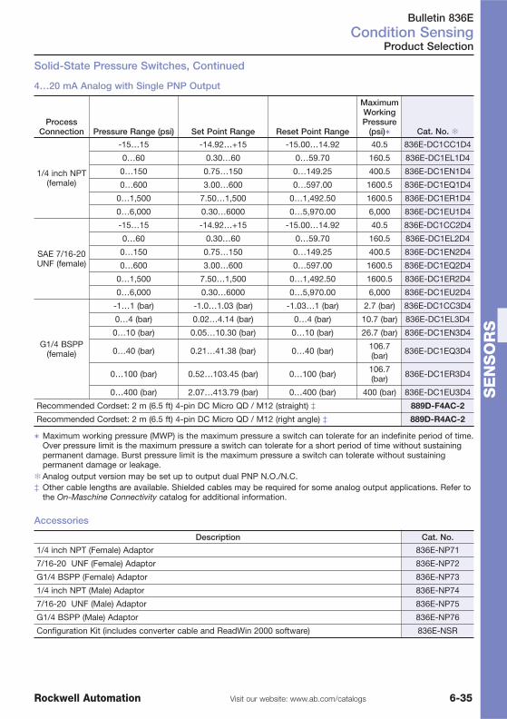
Bulletin 836ECondition Sensing
6-35Visit our website: www.ab.com/catalogsRockwell Automation
SE
NS
OR
S
Accessories
Description Cat. No.
1/4 inch NPT (Female) Adaptor 836E-NP71
7/16-20 UNF (Female) Adaptor 836E-NP72
G1/4 BSPP (Female) Adaptor 836E-NP73
1/4 inch NPT (Male) Adaptor 836E-NP74
7/16-20 UNF (Male) Adaptor 836E-NP75
G1/4 BSPP (Male) Adaptor 836E-NP76
Configuration Kit (includes converter cable and ReadWin 2000 software) 836E-NSR
Product Selection
Solid-State Pressure Switches, Continued
4…20 mA Analog with Single PNP Output
ProcessConnection Pressure Range (psi) Set Point Range Reset Point Range
MaximumWorkingPressure
(psi)� Cat. No. �
1/4 inch NPT(female)
-15…15 -14.92…+15 -15.00…14.92 40.5 836E-DC1CC1D4
0…60 0.30…60 0…59.70 160.5 836E-DC1EL1D4
0…150 0.75…150 0…149.25 400.5 836E-DC1EN1D4
0…600 3.00…600 0…597.00 1600.5 836E-DC1EQ1D4
0…1,500 7.50…1,500 0…1,492.50 1600.5 836E-DC1ER1D4
0…6,000 0.30…6000 0…5,970.00 6,000 836E-DC1EU1D4
SAE 7/16-20UNF (female)
-15…15 -14.92…+15 -15.00…14.92 40.5 836E-DC1CC2D4
0…60 0.30…60 0…59.70 160.5 836E-DC1EL2D4
0…150 0.75…150 0…149.25 400.5 836E-DC1EN2D4
0…600 3.00…600 0…597.00 1600.5 836E-DC1EQ2D4
0…1,500 7.50…1,500 0…1,492.50 1600.5 836E-DC1ER2D4
0…6,000 0.30…6000 0…5,970.00 6,000 836E-DC1EU2D4
G1/4 BSPP(female)
-1…1 (bar) -1.0…1.03 (bar) -1.03…1 (bar) 2.7 (bar) 836E-DC1CC3D4
0…4 (bar) 0.02…4.14 (bar) 0…4 (bar) 10.7 (bar) 836E-DC1EL3D4
0…10 (bar) 0.05…10.30 (bar) 0…10 (bar) 26.7 (bar) 836E-DC1EN3D4
0…40 (bar) 0.21…41.38 (bar) 0…40 (bar) 106.7(bar) 836E-DC1EQ3D4
0…100 (bar) 0.52…103.45 (bar) 0…100 (bar) 106.7(bar) 836E-DC1ER3D4
0…400 (bar) 2.07…413.79 (bar) 0…400 (bar) 400 (bar) 836E-DC1EU3D4
Recommended Cordset: 2 m (6.5 ft) 4-pin DC Micro QD / M12 (straight) ‡ 889D-F4AC-2
Recommended Cordset: 2 m (6.5 ft) 4-pin DC Micro QD / M12 (right angle) ‡ 889D-R4AC-2
� Maximum working pressure (MWP) is the maximum pressure a switch can tolerate for an indefinite period of time.Over pressure limit is the maximum pressure a switch can tolerate for a short period of time without sustainingpermanent damage. Burst pressure limit is the maximum pressure a switch can tolerate without sustainingpermanent damage or leakage.
�Analog output version may be set up to output dual PNP N.O./N.C.‡ Other cable lengths are available. Shielded cables may be required for some analog output applications. Refer to
the On-Maschine Connectivity catalog for additional information.

Bulletin 837ECondition Sensing
6-36 Visit our website: www.ab.com/catalogs Rockwell Automation
SE
NS
OR
S
Product Selection
Solid-State Temperature Switches
Dual PNP Output or 4…20 mA Analog with Single PNP Output
� Media temperature range from -50…150°C (-58…302°F)� Operating temperatures from -40…85°C (-40…185°F)� Industry-leading four-digit 14-segment digital display� Independently programmable dual PNP NO/NC outputs
or 4…20 mA analog outputs� Stainless steel probe� 316L stainless steel construction� IP66 enclosure rating
Dual PNP Output
ProcessConnection
�Set Point Range
°C (°F)Reset Point Range
°C (°F)ProbeLength Cat. No.
1/4 inch NPT(Male)
-49…150° (-57…302°) -50…149.5° (-58…301°) 50 mm(1.96 in.) 837E-DA1BN1A1D4
-49…150° (-57…302°) -50…149.5° (-58…301°) 100 mm(3.93 in.) 837E-DA1BN1A2D4
-49…150° (-57…302°) -50…149.5° (-58…301°) 200 mm(7.87 in.) 837E-DA1BN1A4D4
1/2 inch NPT(Male)
-49…150° (-56.2…302°) -50…149.5° (-58…301.1°)
50 mm(1.96 in.) 837E-DA1BN2A1D4
-49…150° (-57…302°) -50…149.5° (-58…301.1°)
100 mm(3.93 in.) 837E-DA1BN2A2D4
-49…150° (-57…302°) -50…149.5° (-58…301°) 200 mm(7.87 in.) 837E-DA1BN2A4D4
G1/4 BSPP
-49…150° (-57…302°) -50…149.5° (-58…301°) 50 mm(1.96 in.) 837E-DA1BN3A1D4
-49…150° (-57…302°) -50…149.5° (-58…301°) 100 mm(3.93 in.) 837E-DA1BN3A2D4
-49…150° (-57…302°) -50…149.5° (-58…301°) 200 mm(7.87 in.) 837E-DA1BN3A4D4
G1/2 BSPP
-49…150° (-57…302°) -50…149.5° (-58…301°) 50 mm(1.96 in.) 837E-DA1BN4A1D4
-49…150° (-57…302°) -50…149.5° (-58…301°) 100 mm(3.93 in.) 837E-DA1BN4A2D4
-49…150° (-57…302°) -50…149.5° (-58…301°) 200 mm(7.87 in.) 837E-DA1BN4A4D4
Recommended Cordset: 2 m (6.5 ft) 4-pin DC Micro QD / M12 (straight) � 889D-F4AC-2
Recommended Cordset: 2 m (6.5 ft) 4-pin DC Micro QD / M12 (right angle) � 889D-R4AC-2
� Other cable lengths are available. Shielded cables may be required for some analog output applications. Refer tothe On-Maschine Connectivity catalog for additional information.

Bulletin 837ECondition Sensing
6-37Visit our website: www.ab.com/catalogsRockwell Automation
SE
NS
OR
S
Accessories
Product Selection
Solid-State Temperature Switches, Continued
4…20 mA Analog with Single PNP Output
ProcessConnection
�Set Point Range
°C (°F)Reset Point Range
°C (°F)ProbeLength Cat. No. �
1/4 inch NPT(Male)
-49…150° (-57…302°) -50…149.5° (-58…301.1°) 50 mm(1.96 in.) 837E-DC1BN1A1D4
-49…150° (-57…302°) -50…149.5° (-58…301.1°) 100 mm(3.93 in.) 837E-DC1BN1A2D4
-49…150° (-57…302°) -50…149.5° (-58…301.1°) 200 mm(7.87 in.) 837E-DC1BN1A4D4
1/2 inch NPT(Male)
-49…150° (-57…302°) -50…149.5° (-58…301.1°) 50 mm(1.96 in.) 837E-DC1BN2A1D4
-49…150° (-57…302°) -50…149.5° (-58…301.1°) 100 mm(3.93 in.) 837E-DC1BN2A2D4
-49…150° (-57…302°) -50…149.5° (-58…301.1°) 200 mm(7.87 in.) 837E-DC1BN2A4D4
G1/4 BSPP
-49…150° (-57…302°) -50…149.5° (-58…301.1°) 50 mm(1.96 in.) 837E-DC1BN3A1D4
-49…150° (-57…302°) -50…149.5° (-58…301.1°) 100 mm(3.93 in.) 837E-DC1BN3A2D4
-49…150° (-57…302°) -50…149.5° (-58…301.1°) 200 mm(7.87 in.) 837E-DC1BN3A4D4
G1/2 BSPP
-49…150° (-57…302°) -50…149.5° (-58…301.1°) 50 mm(1.96 in.) 837E-DC1BN4A1D4
-49…150° (-57…302°) -50…149.5° (-58…301.1°) 100 mm(3.93 in.) 837E-DC1BN4A2D4
-49…150° (-57…302°) -50…149.5° (-58…301.1°) 200 mm(7.87 in.) 837E-DC1BN4A4D4
Recommended Cordset: 2 m (6.5 ft) 4-pin DC Micro QD / M12 (straight) ‡ 889D-F4AC-2
Recommended Cordset: 2 m (6.5 ft) 4-pin DC Micro QD / M12 (right angle) ‡ 889D-R4AC-2
�Analog output version may be set up to output dual PNP N.O./N.C.‡ Other cable lengths are available. Shielded cables may be required for some analog output applications. Refer to
the On-Maschine Connectivity catalog for additional information.
Description Cat. No.Configuration Kit (includes converter cable and ReadWin 2000 software) 836E-NSR

Bulletin 839ECondition Sensing
6-38 Visit our website: www.ab.com/catalogs Rockwell Automation
SE
NS
OR
S
Product Selection
Solid-State Flow Switches
Dual PNP Output or 4…20 mA Analog with Single PNP Output
� Microprocessor based with no moving parts for longer life andreduced downtime
� Rugged, corrosion resistant 316 stainless steel housing features anIP66 enclosure rating to withstand harsh industrial conditions
� Flow rates of liquid media (calorimetric measuring principle) in therange from 0.03…3 m/s (0.1…9.84 ft/s)
� Industry leading four-digit 14-segment digital display� Dual NO/NC programmable PNP outputs or 4…20 mA analog output
with single PNP output� Stainless steel probe
ProcessConnection
MeasuringRange Response Time Probe Length
Cat. No.
Dual PNP Output
4…20 mA AnalogOutput with Single
PNP Output�
1/4 inch NPT(Male)
Liquids from0.03…3 m/s
(0.1… 9.84 ft/s)Mass flow as arelative value
between 0 and100%
6…12 s
30 mm (1.18 in.) 839E-DA1BA1A3-D4 839E-DC1BA1A3D4
100 mm (3.93in.) 839E-DA1BA1A2-D4 839E-DC1BA1A2D4
1/2 inch NPT(Male)
30 mm (1.18 in.) 839E-DA1BA2A3D4 839E-DC1BA2A3D4
100 mm (3.96in.) 839E-DA1BA2A2D4 839E-DC1BA2A2D4
G1/4 BSPP30 mm (1.18 in.) 839E-DA1BA3A3D4 839E-DC1BA3A3D4
100 mm (3.96in.) 839E-DA1BA3A2D4 839E-DC1BA3A2D4
G1/2 BSPP30 mm (1.18 in.) 839E-DA1BA4A3D4 839E-DC1BA4A3D4
100 mm (3.96in.) 839E-DA1BA4A2D4 839E-DC1BA4A2D4
Sanitary Connection
1…1.5 inchClamp Liquids from
0.03…3 m/s(0.1… 9.84 ft/s)Mass flow as arelative value
between 0 and100%
6…12 s
30 mm (1.18 in.) 839E-DA1BABA3D4 839E-DC1BABA3D4
100 mm (3.96in.) 839E-DA1BABA2D4 839E-DC1BABA2D4
2 inch Clamp30 mm (1.18 in.) 839E-DA1BACA3D4 839E-DC1BACA3D4
100 mm (3.96in.) 839E-DA1BACA2D4 839E-DC1BACA2D4
Base Switch30 mm (1.18 in.) 839E-DA1BA7A3D4 839E-DC1BA7A3D4
100 mm (3.96in.) 839E-DA1BA7A2D4 839E-DC1BA7A2D4
Recommended cordset: 2 m (6.5 ft) 4-pin DC micro (straight) 889D-F4AC-2
Recommended cordset: 2 m (6.5 ft) 4-pin DC micro (right angle) 889D-R4AC-2
� Analog output version may be set up to output dual PNP N.O./N.C.

Bulletin 839ECondition Sensing
6-39Visit our website: www.ab.com/catalogsRockwell Automation
SE
NS
OR
S
Product Selection
ProcessConnection
MeasuringRange Response Time Probe Length
Cat. No.
Dual PNP Output
4…20 mA AnalogOutput with Single
PNP Output�
1/4 inch NPT(Male)
Liquids from0.03…3 m/s
(0.1… 9.84 ft/s)Mass flow as arelative value
between 0 and100%
6…12 s
30 mm (1.18 in.) 839E-DA1BA1A3-D4 839E-DC1BA1A3D4
100 mm (3.93in.) 839E-DA1BA1A2-D4 839E-DC1BA1A2D4
1/2 inch NPT(Male)
30 mm (1.18 in.) 839E-DA1BA2A3D4 839E-DC1BA2A3D4
100 mm (3.96in.) 839E-DA1BA2A2D4 839E-DC1BA2A2D4
G1/4 BSPP30 mm (1.18 in.) 839E-DA1BA3A3D4 839E-DC1BA3A3D4
100 mm (3.96in.) 839E-DA1BA3A2D4 839E-DC1BA3A2D4
G1/2 BSPP30 mm (1.18 in.) 839E-DA1BA4A3D4 839E-DC1BA4A3D4
100 mm (3.96in.) 839E-DA1BA4A2D4 839E-DC1BA4A2D4
Recommended cordset: 2 m (6.5 ft) 4-pin DC micro (straight) 889D-F4AC-2
Recommended cordset: 2 m (6.5 ft) 4-pin DC micro (right angle) 889D-R4AC-2
� Analog output version may be set up to output dual PNP N.O./N.C.
Accessories
Description Cat. No.
Configuration Kit (includes converter cable and ReadWin 2000 software) 836E-NSR
1…1.5 inch Sanitary Clamp 836E-NH7B
2 inch Sanitary Clamp 836E-NH7C
Weld Boss Sealing Taper 837E-NWT
Weld Boss Collar Weld 837E-NWS
Weld Boss Coupling with Sealing Taper 837E-NWR

Bulletin 54RFIndustrial RFID Products
6-40 Visit our website: www.ab.com/catalogs Rockwell Automation
SE
NS
OR
S
Product Selection
54RF General Purpose
� Interfaces available for EtherNet/IP™, ControlNet™ andDeviceNet™, as well as MicroLogix™ (DF1) and 1746backplanes
� Three rugged transceiver styles designed for industrial locations� 1.5 MHz low frequency technology for enhanced immunity to
EMI, interference from metallic reflective surfaces, oil, water, andother potentially disruptive materials
� Seven character read-only or 2 Kbyte read/write tags� Read/write speeds to 200 characters per second (cps) + 25
ms/instruction� Four tag styles with sensing distances of 3.5 inches (100mm)� Reusable Rislan® tags assure long life and reliable performance
in harsh environments
Tags
Transceiver-Tag Maximum Sensing Distance
Tag Memory Cat. No.54RF-TR-ERC 54RF-TR-ERD 54RF-TR-ERE
25 mm 55 mm 80 mm 7 byte 54RF-TG-FFA
25 mm 68 mm 100 mm 7 byte 54RF-TG-FFB
25 mm 68 mm 100 mm 7 byte 54RF-TG-FFB7FP
23 mm 55 mm n/a 2K byte 54RF-TG-GGA2K
45 mm 80 mm 100 mm 2K byte 54RF-TG-GGB2K
Transceivers
Maximum Sensing Distance Cat. No.
25 mm to 45 mm depending on tag style used 54RF-TR-ERC
55 mm to 80 mm depending on tag style used 54RF-TR-ERD
80 mm to 100 mm depending on tag style used 54RF-TR-ERE
Interfaces
Network or Backplane Cat. No.
SLC Backplane Control Interface for FF style tags 54RF-IN-46F
SLC Backplane Control Interface for GG style tags 54RF-IN-46G
MicroLogix DF1 Control Interface for FF style tags 54RF-IN-DF1F
MicroLogix DF1 Control Interface for GG style tags 54RF-IN-DF1G
ControlNet Control Interface for FF style tags 54RF-IN-CNF
ControlNet Control Interface for GG style tags 54RF-IN-CNG
DeviceNet Control Interface for FF style tags 54RF-IN-DNF
DeviceNet Control Interface for GG style tags 54RF-IN-DNG
Ethernet/IP Control Interface for FF style tags 54RF-IN-IPF
Ethernet/IP Control Interface for GG style tags 54RF-IN-IPG
Handhelds, Cables and Spacers see page 6-44

Bulletin 55RFIndustrial RFID Products
6-41Visit our website: www.ab.com/catalogsRockwell Automation
SE
NS
OR
S
Product Selection
55RF High-Speed
� Interfaces available for EtherNet/IP™, ControlNet™ andDeviceNet™, as well as MicroLogix™ (DF1) and 1746backplanes
� Three rugged transceiver styles designed for industrial locations� 1.5 MHz low frequency technology for enhanced immunity to
EMI, interference from metallic reflective surfaces, oil, water, andother potentially disruptive materials
� 8 Kbyte and 32 Kbyte Read/Write tags allow complete buildinstructions and quality test data to be kept with the product
� Read speeds up to 2500 characters per second (cps) and writespeeds up to 1666 cps
� Reusable Rislan® tags assure long life and reliable performancein harsh environments
� Sensing distances up to 70 mm (2.5 inches)
Tags
Transceiver-Tag Maximum Sensing Distance
Tag Memory Cat. No.55RF-TR-ECB 55RF-TR-ECC 55RF-TR-ECD
22 mm 50 mm 70 mm 8K byte 55RF-TG-OXA8K
22 mm 50 mm 70 mm 32K byte 55RF-TG-OXA32K
Transceivers
Maximum Sensing Distance Cat. No.
22 mm with 8K or 32K tag styles 55RF-TR-ECB
40 mm with 8K or 32K tag styles 55RF-TR-ECC
70 mm with 8K or 32K tag styles 55RF-TR-ECD
Interfaces
Network or Backplane Cat. No.
SLC Backplane Control Interface 55RF-IN-46
MicroLogix DF1 Control Interface 55RF-IN-DF1
ControlNet Control Interface 55RF-IN-CN
DeviceNet Control Interface 55RF-IN-DN
Ethernet/IP Control Interface 55RF-IN-IP
Handhelds, Cables and Spacers see page 6-44
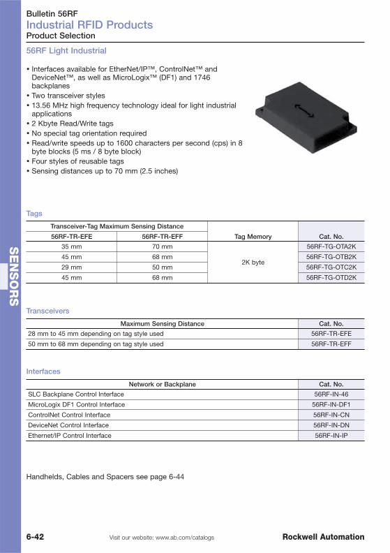
Bulletin 56RFIndustrial RFID Products
6-42 Visit our website: www.ab.com/catalogs Rockwell Automation
SE
NS
OR
S
Product Selection
56RF Light Industrial
� Interfaces available for EtherNet/IP™, ControlNet™ andDeviceNet™, as well as MicroLogix™ (DF1) and 1746backplanes
� Two transceiver styles� 13.56 MHz high frequency technology ideal for light industrial
applications� 2 Kbyte Read/Write tags� No special tag orientation required� Read/write speeds up to 1600 characters per second (cps) in 8
byte blocks (5 ms / 8 byte block)� Four styles of reusable tags� Sensing distances up to 70 mm (2.5 inches)
Tags
Transceiver-Tag Maximum Sensing Distance
Tag Memory Cat. No.56RF-TR-EFE 56RF-TR-EFF
35 mm 70 mm
2K byte
56RF-TG-OTA2K
45 mm 68 mm 56RF-TG-OTB2K
29 mm 50 mm 56RF-TG-OTC2K
45 mm 68 mm 56RF-TG-OTD2K
Transceivers
Maximum Sensing Distance Cat. No.
28 mm to 45 mm depending on tag style used 56RF-TR-EFE
50 mm to 68 mm depending on tag style used 56RF-TR-EFF
Interfaces
Network or Backplane Cat. No.
SLC Backplane Control Interface 56RF-IN-46
MicroLogix DF1 Control Interface 56RF-IN-DF1
ControlNet Control Interface 56RF-IN-CN
DeviceNet Control Interface 56RF-IN-DN
Ethernet/IP Control Interface 56RF-IN-IP
Handhelds, Cables and Spacers see page 6-44

Bulletin 57RFIndustrial RFID Products
6-43Visit our website: www.ab.com/catalogsRockwell Automation
SE
NS
OR
S
57RF Handheld RFID Maintenance and Field Programming Units
Programming Units
� Versions available for 54RF, 55RF and 56RF families� Rugged industrial construction, designed for
programming, maintenance and troubleshooting of tagsin any location
� For additional information, please contact your localsales office.
Description Cat. No.
Handheld RFID Maintenance
RFID Handheld Interface for 54RF-FF Tags 57RF-HH-54FF
RFID Handheld Interface for 54RF-GG & 55RF Tags 57RF-HH-54GG55
RFID Handheld Interface for 56RF Tags 57RF-HH-56
Field Programming Units
Remote Read/Write Head for use with the PM-15/01 57RF-HH-RRH71
Charger Base for PM15/01 Handheld RFID Reader 57RF-HH-SPM15
Accessories
Programming Cable for Field Programmable 54RF-TG-FFB7FP RFID Tags 57RF-HH-54FFPC
BHH Synchronizing Cable 57RF-HH-56SC
BHH Rechargeable Battery Pack & Wall Charger 57RF-HH-56RBP
Product Selection

Bulletin 57RFIndustrial RFID Products
6-44 Visit our website: www.ab.com/catalogs Rockwell Automation
SE
NS
OR
S
Product Selection
57RF Cables
� Shielding designed specifically for transceiver tointerface communications
� Single ended cordsetsfor use with chassis-based andMicroLogix interfaces
� Double ended patchcordsin straight or right angleconfigurations for transceiver to network -interfaces
� PUR jacketing for improved oil and abrasion resistance� Available in lengths up to 1000 feet for 54RF family use
and 150 feet for 55RF and 56RF family systems
Cables
Description Cat. No.
Single ended Transceiver Cable
Single ended Female Cable, 2 m 57RF-DF2
Single ended Female Transceiver Cable, 5 m 57RF-DF5
Male Transceiver Cable
Male to Female Transceiver Cable, 2 m 57RF-DFDMJ2
Male to Female Transceiver Cable, 5 m 57RF-DFDMJ5
Male to Female Transceiver Cable, 10 m 57RF-DFDMJ10
Single ended Transceiver Cable
Single ended right angle Female Transceiver Cable, 2 m 57RF-DR2
Single ended right angle Female Transceiver Cable, 5 m 57RF-DR5
Male to Right Angle Transceiver Cable
Male to Right Angle Female Transceiver Cable, 2 m 57RF-DRDMJ2
Male to Right Angle Female Transceiver Cable, 5 m 57RF-DRDMJ5
Male to Right Angle Female Transceiver Cable, 10 m 57RF-DRDMJ10
Flash Programming Cable
Flash Programming Cable, 1 m 57RF-PCDN-1
Flash Programming Cable, 2 m 57RF-PCDN-2
Ethernet Cable
Ethernet Cable RJ45 to Micro M12, 1 m 57RF-RJ45-1
Ethernet Cable RJ45 to Micro M12, 3 m 57RF-RJ45-3
Ethernet Cable RJ45 to Micro M12, 5 m 57RF-RJ45-5
Ethernet Cable RJ45 to Micro M12, 10 m 57RF-RJ45-10
Spacers
Description Cat. No.
Spacers Ø 30 mm for 56RF 57RF-SP30Q100
Spacers Ø 50 mm for 56RF 57RF-SP50Q100
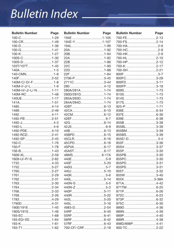
Bulletin Index
100-C.....................................1-29100-CR ..................................1-49100-D.....................................1-36100-G.....................................1-41100-K .....................................1-27100S-C ..................................1-30100S-D ..................................1-37103T/107T.............................1-45140A.........................................1-5140-CMN.................................1-8140F .......................................2-52140M-C/-D/-F.........................1-8140M-I/-J/-L ...........................1-9140M-H/-J/-L/-N .................1-11140M-RC ..............................1-48140UE ....................................1-17141A.......................................1-511485 .......................................4-141489 .......................................2-491492 .......................................4-111492-FB ................................2-511492-J......................................4-31492-L .....................................4-61492-PDE..............................4-101492-RCD .............................2-411492-SP ................................2-43150-C.....................................1-76150-F .....................................1-78156-B .....................................1-431606-XL.................................2-591609-U/-P/-S........................2-621732 .......................................4-331752 .......................................5-271760 .......................................2-271761 .......................................2-291762 .......................................2-311763 .......................................2-301764 .......................................2-341766 .......................................2-331769 .......................................2-261783 .......................................4-291790D ....................................4-31190E/191E ............................1-45190S/191S ............................1-46193-EC ..................................1-68193-ED/-EE...........................1-64193-K .....................................1-61193-T1 ...................................1-62
Bulletin Number Page Bulletin Number Page Bulletin Number Page194E ....................................1-105194E-Y ................................1-107194L .......................................1-9920A.........................................1-9220B.........................................1-9422A.........................................1-8222B.........................................1-8622C ........................................1-9022D.........................................1-8822F .........................................1-842706-P...................................3-452711C ....................................3-44280 .........................................4-12280A/281A ............................1-74280D/281D............................1-74283A/283D............................1-74284A/284D............................1-7442BT ......................................6-1342CA ......................................6-1042CM .....................................6-1242EF .........................................6-742G ........................................6-1442JS .........................................6-944B.........................................6-1345BPD ...................................6-1545CLR....................................6-1645CPD ...................................6-1645PVA ....................................6-1745AST ....................................6-1748MS...................................6-17A440E .........................................5-9440F .......................................5-20440G ........................................5-7440J .......................................5-10440K.........................................5-6440L .......................................5-14440N-S ....................................5-5440N-Z ....................................5-3440P.......................................5-11440R ......................................5-22442L .......................................5-20445L .......................................5-164983-D...................................2-5454RF ......................................6-4055RF ......................................6-4156RF ......................................6-4257RF ......................................6-43700-CF/-CRF........................2-18
700-FE ...................................2-13700-FS...................................2-14700-HA ....................................2-6700-HC ....................................2-8700-HK ....................................2-9700-HL ..................................2-10700-HP ..................................2-12700-K .....................................2-17700-SH ..................................2-21800F .........................................3-7800FC ....................................3-28800FD ....................................3-11800FP ....................................3-18809S.......................................1-73813S.......................................1-73814S.......................................1-73817S.......................................1-73825-P .....................................1-71836E.......................................6-34837E.......................................6-36839E.......................................6-38855B ......................................3-38855BL ....................................3-39855BM ...................................3-39855BS ....................................3-39855E/-D ...................................3-4855F .......................................3-36855H ......................................3-37855P.......................................3-30855PB ....................................3-30855PC....................................3-30855PD....................................3-31855PS ....................................3-31855T .......................................3-32855W .....................................3-40855X ....................................3-38A871A.......................................4-42871TM ...................................6-25871P.......................................6-26872C ......................................6-23873P.......................................6-32875C ......................................6-30889D ......................................4-36889N ......................................4-39889P.......................................4-40889R ......................................4-38898D/898P............................4-41900-TC ..................................2-22
Bulletin Index

Head Office & Johannesburg Branch
Rockwell Automation (Pty) LtdRiverview ParkJanadel AvenueHalfway Gardens 1682MidrandSouth Africawww.rockwellautomation.co.za
Postal address:
P O Box 7096Halfway House 1685South Africa
Tel: +27 (11) 654-9700Fax: +27 (11) 654-9701 (Main) Fax: +27 (11) 654-9702 (Jhb Branch)
Catalogue numbers in bold are typically the highest available products.
Allen-Bradley, ArmorBlock, ArmorStart, ArmorConnect, CompactBlock, Control Tower, DataSite, DeviceLogix, GuardShield, InView, LifeLine, MachineAlert, MatGuard, MicroLogix, Minotaur, PanelView,
PowerFlex, PowerMonitor, PICO, Rockwell Software, SafeZone, SensaGuard, and SMC are trademarks of Rockwell Automation.
Publication EC-RSA-CA006A-EN-P - May 2010 Copyright ©2009 Rockwell Automation, Inc. All Rights Reserved.
Supersedes Publication EC-RSA-CA005A-EN-P – March 2008
Local Distributor
Call your local in-country representativehttp://www.rockwellautomation.com/distributor/
On-Line Product Directory
Our extensive product portfolio is designed to improve your processes throughevery stage of your manufacturing cycle.http://www.rockwellautomation.com/products/
Product Selection Toolbox
Our powerful range of product selection and system configuration tools assist you in choosing and applying our products.http://www.rockwellautomation.com/en/e-tools/
Catalogues
Within our catalogues you’ll find an extensiveselection of essential component products.http://www.ab.com/catalogs/
Rockwell Automation offers a breadth of quality components to fit your specific needs.In order to assist you with your component selection,we offer a variety of configuration and selection tools.