power management guide - mouser electronics€¦ · 6 | power management guide 2014 texas...
TRANSCRIPT

Power ManagementGuide
www.ti.com/power 2014
Pow
er Managem
ent Guide 2014
ww
w.ti.com
/power

Table of ContentsPortable and Line Power Solutions3 Line Power Solutions3 Portable Power Solutions
AC/DC and Isolated DC/DC Power Supply4 Overview5 Power Factor Correction (PFC)6 PWM and Resonant
Controllers10 Gate Drivers
Power Modules (Non-Isolated)14 Overview15 Step-Down (Buck) Modules20 Step-Up (Boost) and Negative
Output Modules
DC/DC Switching Regulators21 Overview21 Step-Down Converters (Line
and Portable Power)31 Step-Up (Boost)/Flyback/
SEPIC and Inverting Converters
35 Buck-Boost Converters36 Controllers (External Switch)41 Charge Pumps
RF Power Solutions43 Overview44 RF DC/DC Converters45 RF Power Detectors
NexFET™ Power MOSFETs46 Single and Dual N- and
P-Channel
Linear Regulators52 Single and Dual LDOs
Battery Management Products56 Overview57 Battery Charger Solutions59 Battery Charger Protection60 Battery Fuel Gauges61 Battery (Li-Ion) Protection61 Wireless Power
LED Lighting62 General Illumination
Texas Instruments (TI) offers complete power solu tions with a full line of high-performance products. These prod-ucts, which range from standard linear regulators to highly efficient DC/DC converters and battery management, are tailored to meet your design chal-lenges. And, TI makes designing easier with leading-edge support tools such as the WEBENCH® Design Center, a broad selection of evaluation modules (EVMs), application notes, comprehen-sive technical documen tation and more. TI also offers samples and small orders (shipped within 24 hours via authorized distributors) to help accelerate your time-to-market.
Included in this selection guide are design factors, featured products, graphic repre-sentations of portfolios and para metric tables.
For information about HiRel and military versions of Power Management prod-ucts, please visit:
www.ti.com/hirel
For information about automotive-qualified Power Management products, please visit:
www.ti.com/automotive
my.TI™ AccountRegister Today!
Keep current on:• New product releases• Design tools• Samples• Evaluation modules• Guides• System block diagrams
www.ti.com/myTI
It’s easy and quick!
Display Power66 LCD Bias and AMOLED Bias
Solutions69 LED Drivers—Backlighting73 LED Drivers—Camera Flash74 LED Drivers—Signage/Linear
Multi-Output Power Management Units (PMUs)78 Overview79 Automotive PMUs82 Special Function PMUs83 Processor Attachment PMUs84 General Purpose PMUs85 Embedded Processor Support
Power Protection, Distribution and Monitoring86 eFuses, Hot Swap Control,
Protection and Monitoring90 Current-Limited and Non-
Current-Limited Load Switches92 Power-over-Ethernet95 USB and Power Switches
Digital Power Control Solutions99 Complete Isolated Telecom
DC/DC PMBus Power Solution100 Isolated and Non-Isolated
Digital Power Controllers
Supervisor and Reset ICs104 Selection Guide
Sequencers106 Selection Guide
Push-Button Controllers107 Product Highlights
Current Power Monitors107 Selection Guide
DDR Power Solutions108 Selection Guide
Resources109 Design Support110 Packaging112 Device Index116 TI Worldwide Technical
Support
2 | Power Management Guide 2014 Texas Instruments
Power Management GuideIntroduction and Contents

Portable and Line Power Solutions
LED Lighting
Display Power
LED Backlighting
Isolated Power SolutionsGeneral Point-of-Load
Solutions
Application-Specific Point-of-Load Solutions
LoadsAC
Line
NexFET TM
Power MOSFETs
Linear Regulators
DC/DC Converters with Integrated FET
Analog and DigitalDC/DC Controllers
Integrated Solutions
Power Modules
PowerFactor
Correctionor AC/DC
PWMControllers
MOSFETDrivers
IsolatedPower
Modules
Power Supervisors and Sequencers
Power-Over-Ethernet Protection and PowerSwitches
System Voltage
AUX
ASICFPGA
USBPeripheral
Memory
Hard Drive
DSP/µC
DSP
Analog Circuitry
Power Delivery(USB Switches, Load Switchesand Hot Swap
Control)
Power MUXControl andProtection
AlternativeEnergySources
Protection:Hot Swap,Reverse-Current
andORing Control
LED Lighting
White-LED Drivers
Display Power
Linear Regulators
Charge Pumps
Buck BoostDC/DC Converter
RF Power
General Point-of-LoadSolutions
Application-Specific Point-of-Load Solutions
Loads
Step-Down (Buck)DC/DC Converters
Step-Up (Boost)DC/DC Converters
Multi-Output Integrated Solutions
(PMU)
Power Supervisors and Reset Controllers
LED Backlighting
Camera-FlashLED Drivers
Flash Memory
DSP/µC
DSP
DCInputs
USB
RechargeableBattery
Battery Management
Power MUXControl andProtection
Battery ChargeManagement
Wireless Power
Nanopower and Energy HarvestingCharger
Front-EndProtection
Battery Fuel Gauges
Lithium-Ion Protectionand Authentication
for Batteries
Mic/Speakers
LED
LCDDisplay
SIM
Wireless RF
USBPeripheral
PA
Line Power Solutions
Portable Power Solutions
Texas Instruments Power Management Guide 2014 | 3
Portable and Line Power Solutions

4 | Power Management Guide 2014 Texas Instruments
AC/DC and Isolated DC/DC Power SuppliesOverview
The TI portfolio of isolated power-conversion solutions covers the complete end-to-end power-supply building blocks from front-end PFC controllers to PWM controllers. These solutions support the most popular isolated-power topologies, including the advanced phase-shifted full-bridge. The portfolio also includes a variety of MOSFET gate drivers that support both primary and secondary MOSFET-driver applications, including synchronous-rectifier driver topologies and many other power-supply support products.
Power-Supply Solutions• PFC controllers:
Transition modeContinuous-current modeInterleavedBridgeless
• PWM controllers:Single-ended: Flyback, forward, active-clampDouble-ended: Half-bridge, phase-shifted full-bridge, push-pull, LLC half-bridgeUCD3K digital control solutions
• Gate drivers:GaN FET driverSynchronous-rectifier driverSingle low-sideDual low-side110-V high-side/low-sideSynchronous-buck
Design Factors
Control MethodAverage-Current Mode (ACM) — Optimum control method to achieve PFC and low harmonic distortion.
Transition Mode (TM) — Simpler, inex-pensive control with high peak currents and filtering requirements.
Interleaved — TM- and ACM-compatible multiphase, high-power, high-density topology. Delivers better EMI, smaller magnetics and reduced ripple currents.
Zero-Voltage-Transition (ZVT) Mode — A type of soft-switching technique, which reduces EMI and allows for higher frequency operations.
Protection• Overvoltage protection (OVP) prevents
output capacitor, switches and load from overcharge condition
• Soft-start (programmable) provides controlled start-up
• Overcurrent protection (OCP) provides protection during overload conditions
Performance• Voltage feed-forward for linearized
performance and faster transient response over wide line voltage range
• Multiplier linearity and zero power detect functions improve light load operation
• Onboard high output current drive capa- bility without external MOSFET drivers
Flexibility• Versatile advanced PWM controllers
and bias supply converters for high-performance secondary-side control
• Ability to work with a wide line voltage range
• Different levels of undervoltage lockout thresholds for self bias and auxiliary bias applications
• Ability to synchronize controllers to eliminate noise issues
Power Level• IEC requirements are applicable to all
power supplies above 75 W• Higher power converters may require
zero-current-switching (ZCS) and ZVT-switching techniques to achieve high efficiencies
• Some of the simpler control techniques not usable at high power levels
Features• From 50 W to 5 kW, TI PFC controllers
deliver EN61000-3-2 compliance• Industry standard architecture• Deliver PF > 0.993• Integrated controllers with on-chip
start-up circuit and MOSFET drivers for high-density primary-side control
• Integrated synchronous rectifier control with pre-bias operation for monotonic start-up
• Superior applications support
IsolatedFeedback
GateDrivers
DigitalIsolation
DistributionBus Voltage(48, 24, 12 V)
Boosted DCOutput
(385 to 400 V)
High-VoltageDC/DC
LocalDC/DC
2.5 V
1.2 V
LocalDC/DC
Sync.BuckDriver
GateDrivers
Rectified AC
AC Line:85 to 265 VAC
PFC
Sync.Rectifiers
Sync.FET GateDrivers

Texas Instruments Power Management Guide 2014 | 5
AC/DC and Isolated DC/DC Power SuppliesPower Factor Correction (PFC)
Interleaved PFCInterleaved PFC is gaining popularity in external and embedded-type power-supply architec tures. It is exceptionally flexible and provides many cost-saving features such as passive-component size reductions, smaller EMI filter ing components and higher efficiencies. TI offers both transition mode (UCC28063) and continuous conduction mode (CCM) (UCC28070) control methods.
Other benefits of interleaving include scalability and ultrathin designs. Scalability allows for addressing many different power levels and applications.
Why Interleave?• Lower system cost from ripple-current
cancellation• Enables ultraslim and high-density
designs• Lower total inductor volume• Smaller or lower-cost EMI filter and
output capacitors• Facilitates higher efficiency
Applications• Digital TV• Telecom power supplies and rectifiers• Professional and consumer audio• Merchant power supplies• Air conditioning and refrigeration
compressors• Variable-speed motors• Low-profile power-supply applications
Get more information: www.ti.com/power or www.ti.com/product/UCC28180
Single-Channel Transition Mode (TM)
Dual-Phase TM Interleaved
Single-ChannelCCM
Dual-Phase CCM Interleaved +
Bridgeless CCM PFC
80 to 200 W 200 to 800 W 800 W to 1 kW+
•UCC28070(A)•UCD3138
•UCC28180•UCD3138•UCC28019A•UC2854(A)•UCC2817/18(A)
•UCC28060/61/63
• UCC28050/51
Per
form
ance
Output Power

6 | Power Management Guide 2014 Texas Instruments
AC/DC and Isolated DC/DC Power SuppliesPWM and Resonant Controllers
LM5027Act-Clamp
with Pre-Bias,HV Start-Up
LM5025Adv. I-ModeAct-Clamp,HV Start-Up
LM5026I-Mode
Act-Clamp,HV Start-Up
UCC2897AAdv. I-ModeAct-Clamp,HV Start-Up
LM5035/9Half-Bridge
with IntegratedDrivers, HV Start-Up
Dual OutputsPush-Pull, Half-Bridge,Full-Bridge
Active-Clamp Forward
UCC25600Resonant
Half-Bridge
UCC2891-4I-Mode
Act-Clamp,HV Start-Up
Current Mode
Voltage Mode
UCC28230/1Intermediate
Bus
Features/Level of Integration
Voltage or Current Mode
LM5045/6Full-Bridge,
with IntegratedDrivers, Pre-Bias,
HV Start-Up
LM(2)5037Dual-Mode PWMController with
Alternating Outputs
UCC28250Half-Bridge
with Pre-Bias
Low- to Medium-Power PWM Controllers (25 W to 350 W)
LM5026Adv. I-ModeAct-Clamp,HV Start-Up
LM5026Adv. V-ModeAct-Clamp,HV Start-Up
UCC25600Resonant Half-Bridge
Secondary Side Control
Push-Pull, Half-Bridge,Full-Bridge
Soft-Switching, ZVT, ZVS(Phase-shifted full-bridge, resonant,active-clamp forward)
UCC28230/1Intermediate Bus
LM5046φ-Shift Full-BridgeIntegrated Drivers,
HV Start-Up, Pre-Bias
UCC2895BiCMOS Adv.φ-Shift PWM
Controller
UCC2897AAdv. I-ModeAct-Clamp,HV Start-Up
Voltage or Current Mode
Current Mode
Voltage Mode
Features/Level of Integration
LM5045Full-Bridge Controller
Integrated Drivers,HV Start-Up, Pre-Bias
LM(2)5037Dual-Mode PWMController with
Alternating Outputs
UCC28250Half-Bridge
with Pre-Bias
UCC28250Half-Bridge with
Pre-Bias Operation
UCC28950Green φ-Shift Full-Bridge
Controller with Synchronous Rectification
UCC28950Green φ-Shift Full-Bridge
Controller with Synchronous Rectification
Medium- to High-Power PWM Controllers (>300 W)
Green-Mode Controllers (Up to 150 W)
UCC28740Constant-Voltage
and Constant-CurrentFlyback ControllerUsing Optocoupler
Feedback
8-Pin Green-Mode Controllers:
UCC28600
UCC28610
LM5021
Features/Level of Integration
UCC28710/1Constant-Voltage
and Constant-Current with 700-V
Start-Up Switch Flyback Controller
UCC28700/1/2/3Constant-Voltage
and Constant-Current with Primary-
Side RegulationFlyback Controller
LM5023Quasi-Resonant
Flyback with Low Standby Power
UCC28720Constant-Voltage
and Constant-Current Controller with Primary-
Side Regulation forBipolar Power Devices

Texas Instruments Power Management Guide 2014 | 7
AC/DC and Isolated DC/DC Power SuppliesPWM and Resonant Controllers
Green Advanced Phase-Shifted Full-Bridge and Synchronous Rectifier ControllerUCC28950
The UCC28950 phase-shifted full-bridge controller offers best-in-class efficiency in today’s high-performance power systems. The UCC28950 implements advanced full-bridge control along with active control of the synchronous rectifier’s output stage. The primary-side signals allow programmable delays to ensure ZVS operation over wide load current and input voltage range, while the load current naturally tunes the second-ary-side synchronous rectifier’s switching delays, maximizing overall system efficiency.
Key Features• Optimized for 90+ efficiency standards• User-programmable operation in DCM
mode with lowered frequency at light load (burst)
• Programmable ramp compensation allows current- or voltage-mode control
• Adaptive ZVS switching over wide input/output range
• Optimal timing outputs for synchronous-rectifier drivers
• Sync in and sync out with 90% phase shift for master/slave interleaved operation of two modules
1
2
3
4
5
6
7
8
9
10
11
12
24
23
22
21
20
19
18
17
16
15
14
13RDCM(hi)
RDCMRCSR7
RA(hi)
RAEF(hi)
RAEF
RA
A
B
C
D
E
F
CVDD
VDD
SYNC
VREF
R5
C2
C1
R4
R3
CREFR2R1
VSENSE
ENABLE
+
–
CT
A
VDD
B
VDD
QA
QB
C
VDD
D
VDD
QC
QD
QE QFE F
VOUT
+
–
VSENSE
UCC27524
C3R6CSS
RAB
RCD
REF
RTMINRT
RSUM
VoltageCurrentSense
VREF
VS UCC28950
DCM
RSUM
RT
TMIN
DELEF
DELCD
DELAB
SS/EN
COMP
EA-
EA+
VREF
ADELEF
ADEL
CS
SYNC
OUTF
OUTE
OUTD
OUTC
OUTB
OUTA
VDD
GND
UCC27524
Phase-ShiftedFull-Bridge
Synchronous RectifiersLight-Load Management
Get more information: www.ti.com/product/UCC28950
Applications• Phase-shifted full-bridge converters• Server, telecom power supplies• Industrial power systems• High-density power architectures• Solar inverters• Electric vehicles• DC motor drives

8 | Power Management Guide 2014 Texas Instruments
AC/DC and Isolated DC/DC Power SuppliesPWM and Resonant Controllers
Selection Guide
Device1
TypicalPowerLevel(W)
Control Method
Topologies
MaximumPractical
Frequency
SupplyVoltage
(V) 700-
V St
art-U
p Circ
uit
110-
V St
art-U
p Circ
uit
SoftStart
Output Drive(Sink/
Source)(A) Package(s) Price*Vo
ltage
Mod
e
Curre
nt M
ode
Avg.
Curre
nt M
ode
Green Mode PWM ControllersUCC28710/1 Up to 25 4 Flyback 130 kHz 9 to 35 4 4 0.025/7 7-SOIC, 6-SOT-23 0.42UCC28700/1/2/3 Up to 30 4 Flyback 130 kHz 9 to 35 4 0.025/7 6-SOT-26 0.35UCC28720 Up to 30 4 Flyback 80 kHz 9 to 35 4 4 0.37/1 8-SOIC 0.40UCC28740 Up to 30 4 Flyback 100 kHz 9 to 35 4 4 0.25/7 8-SOIC 0.42UCC28610 10 to 40 4 Buck, Flyback (SEPIC, Cuk) 140 kHz 9 to 20 — 8-SOIC 0.60LM5023 5 to 100 4 Quasi-Resonant Mode Flyback 130 kHz 8 to 15 4 0.3/0.7 8-MSOP 0.38UCC28600 50 to 150 4 Flyback (SEPIC, Cuk) 130 kHz 30 4 1/0.75 8-SOIC 0.49
General-Purpose Single-Ended ControllersUCC3889 <10 4 Flyback (SEPIC, Cuk) 250 kHz 9 4 0.2/0.15 8-SOIC-W/DIL (PDIP) 0.59LM5020 10 to 100 4 Buck, Boost, Flyback (SEPIC, Cuk) 1 MHz 13 to 100 4 4 1 10-MSOP/QFN 0.90LM5021 10 to 100 4 Flyback (SEPIC, Cuk), Forward (D > 50%) 1 MHz 8 to 30 4 0.7 8-MSOP 0.66LM5022 25 to 100 4 Buck, Boost, Flyback (SEPIC, Cuk) 2 MHz 6 to 60 4 1 10-MSOP 1.13
UCC3800/1/2/3/4/5 10 to 200 4 4Buck, Boost, Flyback (SEPIC, Cuk), Fwd (Including 2-Switch Fwd), Forward (D > 50%) 1 MHz 4.1 to 15 4 1/1 8-TSSOP/SOIC/DIL (PDIP) 1.35
UCC3807-1-2-3 10 to 200 4 4 Buck, Boost, Flyback (SEPIC, Cuk), Forward (D > 50%) 1 MHz 6.9 to 15 4 1/1 8-SOIC/DIL (PDIP) 1.50
UCC3809-1-2 10 to 200 4 4 Buck, Boost, Flyback (SEPIC, Cuk), Forward (D > 50%) 1 MHz 8 to 19 4 0.8/0.4 8-MSOP/TSSOP/SOIC/DIL (PDIP) 0.85
UCC3813-0/1/2/3/4/5 10 to 200 4 4Buck, Boost, Flyback (SEPIC, Cuk), Fwd (In cluding 2-Switch Fwd)2, Forward (D > 50%)2 1 MHz 7.2 to 152 4 1/1 8-TSSOP/SOIC/DIL (PDIP) 0.80
UCC3884 50 to 250 4 4 Buck, Boost, Flyback (SEPIC, Cuk), Forward (D > 50%) 1 MHz 8.9 to 15 4 1/0.5 16-SOIC/DIL (PDIP) 1.60UCC38C40/1/2/3/4/5 10 to 250 4 4 Buck, Boost, Flyback (SEPIC, Cuk), Forward (D > 50%) 1 MHz 5 Options 1/1 8-MSOP/SOIC/DIL (PDIP) 0.95TL3842B/3B/4B/5B 30 to 350 4 4 Buck, Boost, Flyback (SEPIC, Cuk), Forward (D > 50%) 500 kHz 10 to 30 1/1 8/14-SOIC, 8-DIL (PDIP) 0.54UC3842A/3A/4A/5A 30 to 350 4 4 Buck, Boost, Flyback (SEPIC, Cuk), Forward (D > 50%) 500 kHz 10 to 30 1/1 8/14-SOIC, 8-DIL (PDIP) 0.80UC28023 50 to 750 4 4 Buck, Boost, Flyback (SEPIC, Cuk), Forward (D > 50%) 1 MHz 9 to 30 4 1.5/1.5 16-SOIC-W/DIL (PDIP) 1.35
UC3823A/B 50 to 750 4 4 Buck, Boost, Flyback (SEPIC, Cuk), Forward (D > 50%) 1 MHz 9 to 22 4 2/2 16-SOIC-W/DIL (PDIP), 20-PLCC 4.90
Dual Output ControllersLM5015 30 to 250 4 Fwd (Including 2-Switch Fwd) 750 kHz 4.25 to 75 4 1 14-TSSOP 2.05LM5032 30 to 250 4 Flyback (SEPIC, Cuk), Fwd (Including 2-Switch Fwd) 1 MHz 13 to 100 4 4 2.5/2.5 16-TSSOP 1.55LM5034 30 to 250 4 Flyback (SEPIC, Cuk), Fwd (Including 2-Switch Fwd) 1 MHz 8 to 100 4 4 2.5/2.5 20-TSSOP 1.90UC3824 50 to 250 4 4 Push-Pull, Half-Bridge, Full-Bridge 1 MHz 9 to 30 4 1.5/1.5 16-SOIC-W/DIL (PDIP) 4.55
UCC28089 25 to 250 Interleaved Fwd/Flyback/Boost, Push-Pull, Half-Bridge, Full-Bridge 500 kHz 8 to 15 4 0.5/1.0 8-SOIC 0.65
LM5035/A/B/C 50 to 300 4 Half-Bridge 2 MHz 8 to 100 4 4 2/2 28-TSSOP, 20-HTSSOP, 24-QFN 1.90
LM(2)5037 30 to 300 4 4 Push-Pull, Half-Bridge, Full-Bridge 2 MHz 13 to 75/100 4 4 1.2/1.2 16-TSSOP 1.35/1.62LM5039 50 to 300 4 Half-Bridge 2 MHz 8 to 100 4 4 2/2 20-HTSSOP, 24-QFN 1.90LM5045 50 to 400 4 4 Full-Bridge 2 MHz 14 to 100 4 4 1.5/2 28-HTSSOP/QFN 2.25
TL494 or TL594 50 to 500 4Buck, Boost, Flyback (SEPIC, Cuk), Fwd (Including 2-Switch Fwd), Forward (D > 50%), Interleaved Fwd/Flyback/Boost, Push-Pull, Half-Bridge, Full-Bridge
300 kHz 7 to 40 0.2/0.2 16-TSSOP/SOIC/DIL (PDIP) 0.23
TL598 50 to 500 4Buck, Boost, Flyback (SEPIC, Cuk), Fwd (Including 2-Switch Fwd), Forward (D > 50%), Interleaved Fwd/Flyback/Boost, Push-Pull, Half-Bridge, Full-Bridge
300 kHz 7 to 40 0.2/0.2 16-SOIC/DIL (PDIP) 0.81
UC3524A 50 to 500 4 Push-Pull, Half-Bridge, Full-Bridge 250 kHz 8 to 40 4 0.2/0.2 16-SOIC/DIL (PDIP) 1.70
UC3525B - UC3526A 50 to 500 4 Push-Pull, Half-Bridge, Full-Bridge 250 kHz 8 to 40 4 0.2/0.2 16-SOIC/DIL (PDIP), 20-PLCC 1.05
UC3827-1/-2 50 to 500 4 I-Fed/V-Fed Push-Pull 450 kHz 8.4 to 20 4 1/0.8 24-SOIC-W/DIL (PDIP), 28-PLCC 3.50
UCC3808-1/-2/A-1/A-2 50 to 500 4 Push-Pull, Half-Bridge, Full-Bridge 1 MHz 4.3 to 15 4 1.0/0.5 8-TSSOP/SOIC/DIL (PDIP) 1.30UCC38083/4/5/6 50 to 500 4 Push-Pull, Half-Bridge, Full-Bridge 1 MHz 8.3 to 15 4 1.0/0.5 8-TSSOP/SOIC/DIL (PDIP) 1.10
UCC3810 50 to 500 4 4Buck, Boost, Flyback (SEPIC, Cuk), Fwd (Including 2-Switch Fwd), Interleaved Fwd/Flyback/Boost 1 MHz 8.3 to 11 1/1 16-SOIC/DIL (PDIP) 1.85
1 UC2xxx and UCC2xxx devices are extended temperature-range *Suggested resale price in U.S. dollars in quantities of 1,000. New devices are listed in bold red. versions of the UC3xxx and UCC3xxx devices.
2Value varies by part number suffix. Please check datasheet.

Texas Instruments Power Management Guide 2014 | 9
AC/DC and Isolated DC/DC Power SuppliesPWM and Resonant Controllers
Selection Guide (Continued)
Device1
TypicalPowerLevel(W)
Control Method
Topologies
MaximumPractical
Frequency
SupplyVoltage
(V) 700-
V St
art-U
p Circ
uit
110-
V St
art-U
p Circ
uit
SoftStart
Output Drive(Sink/
Source)(A) Package(s) Price*Vo
ltage
Mod
e
Curre
nt M
ode
Avg.
Curre
nt M
ode
Dual Output Controllers (Continued)LM5030 50 to 600 4 Act-Clamp Fwd/Flyback, Half-Bridge, Full-Bridge 1 MHz 14 to 100 4 4 1.5/1.5 20-TSSOP 1.10LM5033 50 to 600 4 Push-Pull, Half-Bridge, Full-Bridge 1 MHz 15 to 100 4 4 1.5/1.5 10-MSOP/QFN 1.00UC28025 50 to 750 4 4 Push-Pull, Half-Bridge, Full-Bridge 1 MHz 9 to 30 4 1.5/1.5 16-SOIC-W/DIL (PDIP) 1.35
UC3825 50 to 750 4 4 Push-Pull, Half-Bridge, Full-Bridge 1 MHz 9 to 30 4 1.5/1.5 16-SOIC-W/DIL (PDIP), 20-PLCC 1.60
UC3825A/B 50 to 750 4 4 Push-Pull, Half-Bridge, Full-Bridge 1 MHz 9 to 22 4 2/2 16-SOIC-W/DIL (PDIP), 20-PLCC 2.65
UC3846/56 50 to 750 4 4 Push-Pull, Half-Bridge, Full-Bridge 1 MHz 8 to 40 4 0.5/0.5 16-SOIC-W/DIL (PDIP), 20-PLCC 1.60
UCC3806 50 to 750 4 4 Push-Pull, Half-Bridge, Full-Bridge 350 kHz 7 to 15 4 0.5/0.516-SSOP/TSSOP/SOIC/
SOIC-W/DIL (PDIP), 20-PLCC
4.10
LM5041/A/B 50 to 800 4 I-Fed/V-Fed Push-Pull 1 MHz 15 to 100 4 4 1/5/1.5 16-TSSOP/QFN 2.15
UCC28250/1 100 to 800 4 4Fwd (Including 2-Switch Fwd), Interleaved Fwd/Flyback/Boost, Act-Clamp Fwd/Flyback, Push-Pull, Half-Bridge 1 MHz 4.7 to 17 4 — 20-TSSOP/QFN 1.70
UCC28220/1 50 to 800 4 Interleaved Fwd/Flyback/Boost 1 MHz/ch. 8 to 14.5 4 4 0.01/0.01 16-TSSOP/SOIC 1.60
Soft-Switching, ZVT and ZVS ControllersLM5025/A/B/C 50 to 250 4 Act-Clamp Fwd/Flyback 1 MHz 8 to 100 4 4 3/3 16-TSSOP/QFN 1.25LM5026 50 to 250 4 Act-Clamp Fwd/Flyback 1 MHz 8 to 100 4 4 3/3 16-TSSOP/QFN 1.30LM5027/A 50 to 250 4 Act-Clamp Fwd/Flyback 1 MHz 8 to 105 4 4 2/2 24-TSSOP, 20-QFN 1.75LM5046 50 to 400 4 4 Φ-Shifted FB 2 MHz 14 to 100 4 4 2/2 28-HTSSOP/QFN 2.45UCC2897A 75 to 600 4 Forward (D > 50%), Act-Clamp Fwd/Flyback 1 MHz 8.5 to 14.5 4 4 2/2, 2/2 20-TSSOP, 16-SOIC 1.50UCC25600 200 W to 1 kW Half-Bridge 350 kHz 11.5 to 18 4 0.4/0.8 8-SOIC 0.80UCC28950 200 W to 2 kW 4 4 4 Φ-Shifted FB 1 MHz 8 to 17 4 — 24-TSSOP 4.25
UCC3895 200 W to 2 kW 4 4 4 Φ-Shifted FB 1 MHz 11 to 17 4Four at 0.1/0.1
20-SOIC-W/DIL (PDIP)/PLCC 4.35
Wide-Input Range Voltage Mode Controllers
UCC35701/2 25 to 250 4Flyback (SEPIC, Cuk), Fwd (Including 2-Switch Fwd), Forward (D > 50%) 700 kHz 8.8 to 15 4 1.2/1.2 14-TSSOP/SOIC/DIL (PDIP) 2.95
UCC35705/6 25 to 250 4Boost, Flyback (SEPIC, Cuk), Fwd (Including 2-Switch Fwd), Forward (D > 50%) 4 MHz 8.0 to 15 0.1/0.1 8-MSOP/SOIC/DIL (PDIP) 0.75
Auxiliary Bias SuppliesTPS55010 <2 4 Fly-Buck™ (Forward Flyback) 2 MHz 2.95 to 6 4 — 16-QFN 0.99UCC25230 1 to 2 Buck, Fly-Buck (Forward Flyback) 445 kHz 12 to 75 4 — 8-SON 1.35LM34927/6/5 3 to 7 Note 2 Buck, Isolated Buck 1 MHz 9 to 100 0.6/0.3/0.15 8-LLP/PSOP 1.65LM5017 3 to 7 Note 2 Buck, Isolated/Non-Isolated Flyback 1 MHz 9 to 100 0.6 8-LLP/PSOP 1.65
Intermediate Bus ControllersUCC28230/1 150 to 500 Half-Bridge, Full-Bridge 2 MHz –0.3 to 20 4 0.2/0.2 12-SON, 14-TSSOP 1.20
Secondary-Side, Post RegulationLM(2)5115/A — 4 Synchronous Secondary-Side Post Regulator 1 MHz 4.5 to 42/75 4 2/2.5 16-TSSOP/QFN 1.35/1.80
1 UC2xxx and UCC2xxx devices are extended temperature-range *Suggested resale price in U.S. dollars in quantities of 1,000. New devices are listed in bold red. versions of the UC3xxx and UCC3xxx devices.
2Value varies by part number suffix. Please check datasheet.

10 | Power Management Guide 2014 Texas Instruments
AC/DC and Isolated DC/DC Power SuppliesGate Drivers
High-Side/Low-Side Bridge Driver Portfolio
Design FactorsSupply Voltage Range — With internal voltage regulators, MOSFET drivers can operate over a wide input voltage range, making them flexible for many applications.
Number of Outputs — Single and dual drivers are available to complement DC/DC switching and motor control applications.
Output Configuration — Inverting, non-inverting, AND and NAND configurations are available.
Low-Side Gate Driver Portfolio
0 100
LM510xB
LM5113 GaN Gate Driver
120118107
1
2
5
3
4
Bootstrap Voltage Range (VHB)
Peak
Out
put C
urre
nt (
A)
LM510xC
UCC27200/1, UCC27200A/1A
LM(2)5101
LM510xA
UCC27210A/UCC27211A
UCC27516/7/8/9
LM5110/1 (D)
UCC27531/2/3/6/7/8
UCC27611 GaN FET Driver
UCC27511/2
LM5114
4035302520151050
2
4
8
5
9
7
Supply Voltage Range (VDD)
Peak
Out
put C
urre
nt (
A)
TPS2811/2/3* (D), TPS2816/7/8/9*
TPS2813/4/5 (D), TPS2828/9
UCC37321/2
UCC27523/4/5/6/8A (D)
LM5112
(D) Dual Output
*With use of internal regulator
UCC27423/4/5 (D),UCD7100,
UCD7201 (D)
UCC2721xA• 4-A next generation of popular
UCC2720x has 120-V boot voltage, –10-V input-voltage capa bility and ESD enhancements
LM510xx Family• Drive capability scales with power-
converter requirements
LM5113• Industry’s only 100-V driver for
enhancement-mode GaN FETs
Product Highlights
UCC2751x and UCC2752xA• Asymmetrical drive and split output
options available on select single-channel drivers
• Best-in-class propagation delay and higher VDD compatibility with IGBT power switches
• UCC27528 features CMOS input thresholds
UCC27531• FET and IGBT single-gate drivers• 2.5 A and 5 A, 35-V maximum VDD
LM5114• Next-generation 7.6-A, 12-ns
single-channel MOS and GaN FET-compatible driver
UCC27611• High-speed 5-V GaN FET driver
Product Highlights
New single-channel low-side drivers offer split outputs (for independent source and sink to allow optimization of switch timing) and asymmetrical drive (higher sink than source current) for faster transition through Miller Plateau.

Texas Instruments Power Management Guide 2014 | 11
AC/DC and Isolated DC/DC Power SuppliesGate Drivers
2.5-A/5-A, 35-V Max Single-Gate Driver for FETs, IGBTs and SiC FETsUCC27531
Advantages over Discrete Design• Built-in level shifting• Flexibility: Inverting and non-inverting configurations• Matches parasitic and improves layout• Reduced number of devices (three needed for discrete design)• Reduced overall cost—transistor/FET and PC board space
Key Features• High VDD: 35 V allows significant margin• Strong output-drive capability: 2.5-A
source/5-A sink allows fast charging• Fastest propagation time: 17-ns
typical delay• High reliability: UVLO setting and rail-
to-rail output voltage provide system protection
• Negative-input-voltage handling allows driver to support “noisy” industrial designs
• Can be used for low side and high side• Used with TI’s UCD3138 digital power
controller or C2000™ microcontrollers
Applications• Solar inverters• Motor control• UPS• HEV/EV chargers• Switch-mode power• Intelligent power modules
Get more information: www.ti.com/product/UCC27531
www.ti.com/lit/slua669
www.ti.com/tool/UCC27531EVM-184
UCC27531EVM-184 evaluation module.
EN
IN
VDD
OUTH
OUTL
GND
18 V
13 V
UCC27531
+
–1
2
3
6
5
4
+
+
–
–
1
2
3
6
5
4
IN
EN
GND
OUTL
OUTH
VDD

12 | Power Management Guide 2014 Texas Instruments
AC/DC and Isolated DC/DC Power SuppliesGate Drivers
Selection Guide
DeviceNo. of
ChannelsOutput
Configuration Output Type1
Peak IOUT Source/Sink
(A)Rise/Fall Time (ns)
VCC Range (V)
Prop Delay (ns)
Input Threshold Enable
Dead Time
ControlProtection Features2
Internal Regulator Price*
General-Purpose Low-Side DriversUCC37321 1 Inverting TrueDrive™ 9/9 20/20 4 to 15 30 TTL/CMOS 4 — — — 0.99
UCC37322 1 Non-inverting TrueDrive 9/9 20/20 4 to 15 30 TTL/CMOS 4 — — — 0.99
LM5112 2 Non-inverting Split 7/3 14/12 3.5 to 15 25 CMOS — — 4 — 0.50
UCC27523 2 Inverting — 5/5 9/7 4.5 to 18 14 TTL 4 — — — 0.75
UCC27524A 2 Non-inverting — 5/5 9/7 4.5 to 18 14 TTL 4 — — — 0.75
UCC27525A 2 See Note 3 — 5/5 9/7 4.5 to 18 14 TTL 4 — — — 0.75
UCC27526A 2 See Note 3 — 5/5 9/7 4.5 to 18 14 TTL 4 — — — 0.75
LM5111 2 Non-inverting Split 5/3 14/12 3.5 to 15 25 TTL — — 4 — 0.65
LM5110 2 Non-inverting Split 5/2 14/12 3.5 to 15 25 TTL — — 4 — 0.65
LM5134 2 Non-inverting with Pilot output Split 4.5/7.6
0.66/0.82 5.3/4.7 4 to 12.6 12 TTL/CMOS — — — — 0.60
UCC27511 1 Non-inverting Split 4/8 9/9 4.5 to 18 14 Dual input TTL — — — — 0.60
UCC27512 1 Non-inverting — 4/8 9/7 4.5 to 18 14 Dual input TTL — — — — 0.60
UCC27516 1 See Note 3 — 4/4 9/7 4.5 to 18 14 TTL — — — — 0.49
UCC27517A 1 See Note 3 — 4/4 9/7 4.5 to 18 14 TTL — — — — 0.49
UCC27518 1 Inverting — 4/4 9/7 4.5 to 18 14 CMOS — — — — 0.49
UCC27519 1 Non-inverting — 4/4 9/7 4.5 to 18 14 CMOS — — — — 0.49
UCD7100PWP 1 Uncommitted/ Non-inverting TrueDrive 4/4 10/10 4.5 to 16 20 CMOS/TTL — Adaptive — — 0.99
UCD7201PWP 2 Uncommitted/ Non-inverting TrueDrive 4/4 10/10 4.5 to 16 20 CMOS/TTL — Adaptive — — 1.20
TPS2812 2 Non-inverting TrueDrive 2/2 25/25 4 to 40 40 CMOS — — — 4 0.90
TPS2814 2 Dual 2-input AND; one inverting TrueDrive 2/2 25/25 4 to 14 40 CMOS — — — — 0.90
TPS2828 1 Inverting TrueDrive 2/2 25/25 4 to 14 40 CMOS — — — — 0.60
TPS2829 1 Non-inverting TrueDrive 2/2 25/25 4 to 14 40 CMOS — — — — 0.60
LM5114A/B 1 Non-inverting Split 1.3/7.6 8/3.2 4 to 12.6 — TTL/CMOS — — — — 0.60
UCC27611 1 See Note 3 — –4/8 5/5 — 14 TTL — — — — 0.85
UCC27531 1 Non-inverting — –2.5/5 15/7 — 17 TTL — — — — 0.75
UCC27532 1 Non-inverting — –2.5/5 15/7 — 17 CMOS — — — — 0.75
UCC27533 1 See Note 3 — –2.5/5 15/8 — 15 TTL — — — — 0.75
UCC27536 1 Inverting — –2.5/5 15/8 — 15 TTL — — — — 0.75
UCC27537 1 Non-inverting — –2.5/5 15/8 — 15 TTL — — — — 0.75
UCC27538 2 Non-inverting — –2.5/5 15/8 — 15 TTL — — — — 0.75
Synchronous-Rectifier DriversUCC24610 Non-inverting — 3/3 30/25 4.5 to 5.5 44 CMOS/TTL 4 Adaptive 4 — 0.75
Synchronous Buck DriversTPS2838 2 Non-inverting TrueDrive 4/4 120 10 to 15 40 TTL 4 Adaptive — 4 1.30
TPS2839 2 Inverting TrueDrive 4/4 120 10 to 15 40 TTL 4 Adaptive — 4 1.30
TPS2848 2 Non-inverting TrueDrive 4/4 120 10 to 15 20 TTL 4 Adaptive — 4 1.25
TPS2849 2 Inverting TrueDrive 4/4 120 10 to 15 20 TTL 4 Adaptive — 4 1.25
UCD7230 2 Non-inverting CMOS 4/4 10/10 4.5 to 15.5 25 CMOS/TTL — Adaptive Adjustable — 0.80
UCC27221 2 Inverting TrueDrive 3.3/3.3 20/20 3.7 to 20 82/103 TTL — PGD4 — 4 1.70
UCC27222 2 Non-inverting TrueDrive 3.3/3.3 20/20 3.7 to 20 82/103 TTL — PGD4 — 4 1.70
UCC27223 2 Non-inverting TrueDrive 3.3/3.3 25/35 4.15 to 20 82/103 TTL 4 PGD4 — 4 1.70
TPS2830 2 Non-inverting TrueDrive 2.4/2.4 50/50 4.5 to 15 75 CMOS 4 Adaptive OVPC — 1.05
TPS2831 2 Inverting TrueDrive 2.4/2.4 50/50 4.5 to 15 75 CMOS 4 Adaptive OVPC — 1.05
TPS2832 2 Non-inverting TrueDrive 2.4/2.4 50/50 4.5 to 15 75 CMOS — Adaptive — — 1.001 Output type: TrueDrive is the hybrid bipolar/CMOS output architecture for improved current drive capability at low voltages (at Miller threshold).
2 OVPC = overvoltage protection crowbar, UVLO = undervoltage lockout.3One inverting, one non-inverting.
4Predictive Gate Drive™.5Maximum boot voltage at HS pin.*Suggested resale price in U.S. dollars in quantities of 1,000.
New devices are listed in bold red.

Texas Instruments Power Management Guide 2014 | 13
AC/DC and Isolated DC/DC Power SuppliesGate Drivers
Selection Guide (Continued)
DeviceNo. of
ChannelsOutput
Configuration Output Type1
Peak IOUT Source/Sink
(A)Rise/Fall Time (ns)
VCC Range (V)
Prop Delay (ns)
Input Threshold Enable
Dead Time
ControlProtection Features2
Internal Regulator Price*
Synchronous Buck Drivers (Continued)TPS2833 2 Inverting TrueDrive 2.4/2.4 50/50 4.5 to 15 75 CMOS — Adaptive — — 1.00
TPS2834 2 Non-inverting TrueDrive 2.4/2.4 30/30 4.5 to 15 70 TTL 4 Adaptive OVPC — 1.05
TPS2835 2 Inverting TrueDrive 2.4/2.4 30/30 4.5 to 15 70 TTL 4 Adaptive OVPC — 1.05
TPS2836 2 Non-inverting TrueDrive 2.4/2.4 30/30 4.5 to 15 70 TTL — Adaptive — — 1.25
TPS2837 2 Inverting TrueDrive 2.4/2.4 30/30 4.5 to 15 70 TTL — Adaptive — — 1.25
TPS28225 2 Non-inverting CMOS 2/4 10/10 4.5 to 8.8 14 TTL/CMOS 4 Adaptive UVLO — 0.60
TPS28226 2 Non-inverting CMOS 2/4 10/10 4.5 to 8.8 14 TTL/CMOS 4 Adaptive UVLO — 0.60
High-Side Low-Side Drivers—Half Bridge, Full BridgeUCC27210 2 Non-inverting — 4/4 12/9 to 1155 20 CMOS — — UVLO — 1.40
UCC27211 2 Non-inverting — 4/4 12/9 to 1155 20 TTL — — UVLO — 1.40
LM25101A/B/C 2 Non-inverting CMOS 3/3 8/8 to 80 25 TTL — — UVLO — 0.49
LM5100A/B/C 2 Non-inverting CMOS 3/3 8/8 to 118 25 CMOS — — UVLO — 1.25
LM5101A/B/C 2 Non-inverting CMOS 3/3 8/8 to 118 25 TTL — — UVLO — 1.25
UCC27200/A 2 Non-inverting TrueDrive 3/3 8/7 to 1105 20 CMOS — — UVLO — 1.30
UCC27201/A 2 Non-inverting TrueDrive 3/3 8/7 to 1105 20 TTL — — UVLO — 1.30
LM5113 2 Non-inverting GaN FET 1.2/5 4/4 to 1005 30 TTL — — UVLO — 1.651 Output type: TrueDrive is the hybrid bipolar/CMOS output architecture for improved current drive capability at low voltages (at Miller threshold).
2 OVPC = overvoltage protection crowbar, UVLO = undervoltage lockout.3One inverting, one non-inverting.
4Predictive Gate Drive™.5Maximum boot voltage at HS pin.*Suggested resale price in U.S. dollars in quantities of 1,000.
New devices are listed in bold red.
14 | Power Management Guide 2014 Texas Instruments
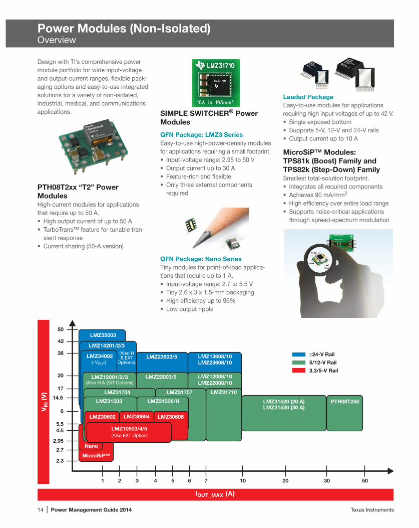
Leaded PackageEasy-to-use modules for applications requiring high input voltages of up to 42 V.• Single exposed bottom• Supports 5-V, 12-V and 24-V rails• Output current up to 10 A
MicroSiP™ Modules: TPS81k (Boost) Family and TPS82k (Step-Down) FamilySmallest total-solution footprint.• Integrates all required components• Achieves 90 mA/mm2
• High efficiency over entire load range• Supports noise-critical applications
through spread-spectrum modulation
Power Modules (Non-Isolated)Overview
Design with TI’s comprehensive power module portfolio for wide input-voltage and output-current ranges, flexible pack-aging options and easy-to-use integrated solutions for a variety of non-isolated, industrial, medical, and communications applications. SIMPLE SWITCHER® Power
Modules
QFN Package: LMZ3 SeriesEasy-to-use high-power-density modules for applications requiring a small footprint.• Input-voltage range: 2.95 to 50 V• Output current up to 30 A• Feature-rich and flexible• Only three external components
required
7
LMZ31704
LMZ31506/H
MicroSiP™
Nano
14.5
2.95
1 2 3 4 5 6 10 20 30 50
LMZ3500350
LMZ23603/5
42
36LMZ13608/10LMZ23608/10
20
6
4.55.5
2.7
2.3
LMZ34002
17
≥24-V Rail
5/12-V Rail
3.3/5-V Rail
IOUT_MAX (A)
VIN
(V)
PTH08T250LMZ31520 (20 A)LMZ31530 (30 A)
LMZ31710
LMZ12008/10LMZ22008/10
LMZ31707
LMZ22003/5LMZ12001/2/3(Also H & EXT Options)
LMZ31503
LMZ30606LMZ30604LMZ30602
LMZ10503/4/5 (Also EXT Option)
LMZ14201/2/3(Also H& EXT
Options) (–VOUT)
PTH08T2xx “T2” Power ModulesHigh-current modules for applications that require up to 50 A.• High output current of up to 50 A• TurboTrans™ feature for tunable tran-
sient response• Current sharing (50-A version)
QFN Package: Nano SeriesTiny modules for point-of-load applica-tions that require up to 1 A.• Input-voltage range: 2.7 to 5.5 V• Tiny 2.6 x 3 x 1.5-mm packaging• High efficiency up to 96%• Low output ripple

Texas Instruments Power Management Guide 2014 | 15
Power Modules (Non-Isolated)Step-Down (Buck) Modules
SIMPLE SWITCHER® QFN Power ModulesLMZ31710
Key Features• World’s smallest 10-A power solution in
a tiny 10 x 10 x 4.3-mm QFN package• 2.95- to 17-V input• 0.6- to 5.5-V output up to 10 A• Pin-compatible with LMZ31707 (7 A)
and LMZ31704 (4 A)
SIMPLE SWITCHER® QFN Power Modules Selection Guide
DeviceIOUT (A)
VIN (V)
VOUT (V)
Package θJA
(°C/W)
Switching Frequency
(kHz)
Features
EVM Package(s) Price*
Power Good Pin
Sync Pin
Adj. Soft Start
180° Out of Phase
Sequencing/ Tracking
Current Sharing
Low Input VoltageLMZ30602 2 2.95 to 6.0 0.8 to 3.6 12 500 to 2000 4 4 4 4 4 39 QFN (9x11x2.8 mm) 2.95LMZ30604 4 2.95 to 6.0 0.8 to 3.6 12 500 to 2000 4 4 4 4 4 39 QFN (9x11x2.8 mm) 3.80LMZ30606 6 2.95 to 6.0 0.8 to 3.6 12 500 to 2000 4 4 4 4 4 4 39 QFN (9x11x2.8 mm) 4.50
Mid Input VoltageLMZ31503 3 4.5 to 14.5 0.8 to 5.5 13 330 to 780 4 4 4 4 4 47 QFN (9x15x2.8 mm) 4.25LMZ31704 4 2.95 to 17 0.6 to 5.5 13 200 to 1200 4 4 4 4 4 4 4 44 QFN (10x10x4.3 mm) 5.25LMZ31506 6 4.5 to 14.5 0.6 to 5.5 13 250 to 780 4 4 4 4 4 4 47 QFN (9x15x2.8 mm) 5.45LMZ31707 7 2.95 to 17 0.6 to 5.5 13 200 to 1200 4 4 4 4 4 4 4 44 QFN (10x10x4.3 mm) 6.50LMZ31710 10 2.95 to 17 0.6 to 5.5 13 200 to 1200 4 4 4 4 4 4 4 44 QFN (10x10x4.3 mm) 8.95LMZ31520 20 4.5 to 14.5 0.6 to 2.8 8.6 500/900 4 4 4 4 68 QFN (15x16x5.8 mm) 14.00LMZ31530 30 4.5 to 14.5 0.6 to 2.8 8.6 500/900 4 4 4 4 68 QFN (15x16x5.8 mm) 17.00
Wide Input VoltageLMZ35003 2.5 7 to 50 2.5 to 15 12 400 to 1000 4 4 4 4 4 41 QFN (9x11x2.8 mm) 7.95LMZ34002 2 4.5 to 40 –3 to –17 14 700 to 900 4 4 4 41 QFN (9x11x2.8 mm) 6.75
All of the above devices have undervoltage lockout and thermal protection built in. New devices are listed in bold red.*Suggested resale price in U.S. dollars in quantities of 1,000.
WEBENCH® models available for all SIMPLE SWITCHER® QFN devices: www.ti.com/webench
High-power efficiency from 5 V and 12 V. Great thermal efficiency even without forced air. Capable of current sharing up to six devices for 60 A.
• Current sharing up to 60 A• Low noise: Meets EN55022 Class B
emissions• Wide operating temperature: Up to
125°C TJ
Get more information: www.ti.com/LMZ3
www.ti.com/product/LMZ31710 (10 A) or LMZ31707 (7 A) or LMZ31704 (4 A)
0 2 31 4 5 6 7 8 9 10
Effi
cien
cy (%
)
Output Current (A)
100
90
80
70
60
50
40
VO = 5.0 V, fSW = 1 MHz VO = 3.3 V, fSW = 750 kHz VO = 2.5 V, fSW = 750 kHz VO = 1.8 V, fSW = 500 kHz VO = 1.2 V, fSW = 300 kHz VO = 0.9 V, fSW = 250 kHz
PVIN = VIN = 12 V
20
30
40
50
60
70
80
90
0 2 4 6 8 10
Am
bie
nt
Tem
pe
ratu
re (°
C)
Output Current (A)
VO ≤ 1.8 V, fSW = 500 kHz VO = 2.5 V, fSW = 750 kHz VO = 3.3 V, fSW = 750 kHz VO = 5.0 V, fSW = 1 MHz
Airflow = 0 LFM

16 | Power Management Guide 2014 Texas Instruments
Power Modules (Non-Isolated)Step-Down (Buck) Modules
SIMPLE SWITCHER® Nano Modules
Device
Output Current (max)
(A)
Input Voltage
(V)
Adjustable Output Voltage
(V)
Operating Junction Temperature
(°C) FeaturesFrequency
(kHz) Eco-mode™Power Good
CISPR22 Class B EMI
Package Size (mm) Price*
LMZ10500/01 0.65/1 2.7 to 5.5 0.6 to 3.6 –40 to 125 EN, SS 2000 4 2.6 x 3 x 1.5 1.30/1.50*Suggested resale price in U.S. dollars in quantities of 1,000.
SIMPLE SWITCHER® Nano ModulesThe new SIMPLE SWITCHER nano modules combine ease of use and high performance in a tiny solution size. Nano modules provide enhanced system performance and can be used to reduce board area in applications with space and height limitations.
Easy-to-Use Package• 2.6 x 3 x 1.5-mm footprint• Eight pins and a thermal pad• 50°C/W θJA
• MSL3• 260°C peak reflow temperature• No exposed die
1.6-A DC-DC Converter Module Achieves Less Than 9-mm2 FootprintTPS82681The TPS8268x series of MicroSiP™ modules are step-down (buck) converters with integrated inductor and input/output capacitors. They can achieve greater than 5-W output power at a total solution size of less than 9 mm2 and 1 mm high, simplifying design and saving up to 50% more board space than complete solutions. The 6-MHz, 1.6-A TPS82681 module supports an output power density of 580 mW/mm3. With an input voltage range of 2.3 to 5.5 V, the TPS8268x series also achieves a power efficiency of up to 92%, which enables it to efficiently manage 5 W in a module format of less than 9 mm3. The modules are suited for noise-critical applications through their PWM frequency dithering.
Key Features• Smallest solution size: Achieves a
solution less than 9 mm2 and 1 mm high, providing a power density of 580 mW/mm3
• Simplifies design: High integration, including passives and capacitors, significantly reduces the effort required for hardware design and layout
• High performance: Up to 92% peak efficiency and high efficiency over a wide load range
Applications• Cell phones, smartphones, tablet PCs• Surveillance cameras• Fiber optics• Portable medical equipment• USB powered applications
VIN SW
FB
MODE
GND
EN
TPS82681 MicroSiP™ Module
L
Enable
DC/DC Converter
GND
ModeSelection
VIN2.3 to 5.5 V
VOUT1.8 V at 1.6 A
CINCOUT
Get more information: www.ti.com/microsip
MicroSiP™ Modules
MicroSiP™ Power Modules Selection Guide
DeviceBase
FunctionIOUT (mA)
VIN (V)
Fixed VOUT (V)
Peak Efficiency
(%)
Switching Frequency
(typ) (kHz)
Quiescent Current
(typ) (µA)
Shutdown Current
(typ) (µA)
Active Output
Capacitor Discharge
Total Solution
Size (mm2)
MicroSiP™ Package EVM
Features and Differentiators Price*
Fully Integrated Solutions (Inductor plus input/output capacitors on device)
TPS82740 Step-Down 300 2.2 to 5.5 1.8 to 3.3 95 3000 0.36 0.07 4 9 9 4Load switch; 4-pin V-Select 1.50
TPS82695 Step-Down 500 2.3 to 4.35 2.5 to 2.85 95 4000 24 0.5 4 6.7 8 4 1.15TPS82671 Step-Down 600 2.3 to 4.8 1.0 to 1.9 90 5500 17 0.5 4 6.7 8 4 Spread spectrum 1.15TPS82693 Step-Down 800 2.3 to 4.8 2.2 to 3.2 95 3000 21 0.5 4 6.7 8 4 Spread spectrum 1.25TPS82681 Step-Down 1600 2.3 to 5.5 0.8 to 3.3 92 6000 20 0.5 4 6.7 9 4 Spread spectrum 1.60
All of the above devices have undervoltage lockout and thermal protection built in. Preview devices are listed in bold teal.*Suggested resale price in U.S. dollars in quantities of 1,000.

Texas Instruments Power Management Guide 2014 | 17
Power Modules (Non-Isolated)Step-Down (Buck) Modules
SIMPLE SWITCHER® Leaded Power ModulesThe SIMPLE SWITCHER leaded power modules allow you to design and optimize robust power supplies with a minimum set of external com po nents. All SIMPLE SWITCHER power modules provide you with low EMI, excellent thermal perform ance and pin-to-pin compatibility for added design flexibility. Plus, SIMPLE SWITCHER power modules utilize WEBENCH® Power Designer online design tools, feature evaluation boards and reference designs, and include application notes and videos to make design easy.
SIMPLE SWITCHER® LMZ1-Series Power Modules
Device
Output Current (max)
(A)
Input Voltage
(V)
Adjustable Output Voltage
(V)
Peak Efficiency
(%)
Operating Junction
Temperature (°C) Features
EMI EN55022/CISPR22 Class B Certification
Package(s) Price*Radiated Conducted1
LMZ10503/04/05 3/4/5 2.95 to 5.5 0.8 to 5 96 –40 to 125 EN, SS 4 4 TO-PMOD-7 3.95/4.50/4.95
LMZ12001/02/03 1/2/3 4.5 to 20 0.8 to 6 92 –40 to 125 EN, SS 4 4 TO-PMOD-7 4.46/5.10/5.95
LMZ14201/02/03 1/2/3 6 to 42 0.8 to 6 90 –40 to 125 EN, SS 4 4 TO-PMOD-7 6.18/7.13/8.95
LMZ12008/10 8/10 6 to 20 0.8 to 6 92 –40 to 125 EN, SS 4 4 TO-PMOD-11 10.93/13.30
LMZ13608/10 8/10 6 to 36 0.8 to 6 92 –40 to 125 EN, SS 4 4 TO-PMOD-11 15.68/17.101Additional input filter required. *Suggested resale price in U.S. dollars in quantities of 1,000.
Up to 5 A Up to10 A
Easy-to-Use Packaging
Key Features• Integrated shielded inductor• Precision enable, external soft-start,
and tracking for sequencing• Best-in-class thermal performance• Low output voltage ripple• Standard junction temperature grade:
–40 to +125°C• Easy-to-use package with single
exposed copper bottom• Passes EN55022 (CISPR22) Class
B Radiated and Conducted EMI Standard
Extended Temperature (EXT) Family of Power ModulesThe SIMPLE SWITCHER EXT power modules provide excellent performance in the most extreme conditions, with extended ambient temperatures guaranteed down to –55°C and shock and vibration compliant to meet military MIL-STD-883 standards.
High Output Voltage and Extended Temperature Power Modules
Device
Output Current (max)
(A)
Input Voltage
(V)
Adjustable Output Voltage
(V)
Peak Efficiency
(%)
Operating Junction
Temperature (°C) Features
EMI EN55022/CISPR22 Class B Certification
Shock and Vibration Compliant Package(s) Price*Radiated Conducted1
LMZ10503/04/05EXT 3/4/5 2.95 to 5.5 0.8 to 5 96 –55 to 125 EN, SS 4 4 4 TO-PMOD-7 12.60/13.50/14.40
LMZ12001/02/03EXT 1/2/3 4.5 to 20 0.8 to 6 92 –55 to 125 EN, SS 4 4 4 TO-PMOD-7 9.50/11.40/13.80
LMZ14201/02/03EXT 1/2/3 6 to 42 0.8 to 6 94 –55 to 125 EN, SS 4 4 4 TO-PMOD-7 12.40/14.30/17.20
LMZ14201H/02H/03H 1/2/3 6 to 42 5 to 24 97 –40 to 125 EN, SS 4 4 TO-PMOD-7 6.18/7.13/8.951Additional input filter required. *Suggested resale price in U.S. dollars in quantities of 1,000.
High Output Voltage Power ModulesThe LMZ1420xH SIMPLE SWITCHER power modules have an output voltage range from 5 to 30 V. These power modules are a good choice for intermediate rail conversions, powering fans or other types of non-traditional points of load, and for sensing applications requiring voltages below –6 V.
SIMPLE SWITCHER® LMZ2-Series Power Modules
Device
Output Current (max)
(A)
Input Voltage
(V)
Adjustable Output Voltage
(V)
Operating Junction Temperature
(°C) Features
EMI EN55022/CISPR22 Class B Certification
Package(s) Price*Radiated Conducted1
LMZ22003/5 3/5 6 to 20 0.8 to 5 –40 to 125 EN, SS, Freq Sync 4 4 TO-PMOD-7 5.50/6.25
LMZ23603/5 3/5 6 to 36 0.8 to 6 –40 to 125 EN, SS, Freq Sync 4 4 TO-PMOD-7 9.85/12.50
LMZ22008/10 8/10 6 to 20 0.8 to 6 –40 to 125 EN, SS, Freq Sync, Current Share 4 4 TO-PMOD-11 11.50/14.00
LMZ23608/10 8/10 6 to 36 0.8 to 6 –40 to 125 EN, SS, Freq Sync, Current Share 4 4 TO-PMOD-11 16.50/18.001Additional input filter required. *Suggested resale price in U.S. dollars in quantities of 1,000.

18 | Power Management Guide 2014 Texas Instruments
Power Modules (Non-Isolated)Step-Down (Buck) Modules
16-A, 4.5-V to 14-V Input, POL Module with TurboTrans™ TechnologyPTH08T220W
+
RSET1%0.05 Ω(Required)
RUVLO1%0.05 Ω(Optional)
CI330 µF(Required)
CO220 µF(Required)
RTT1%0.05 Ω(Optional)
PTH08T220W
2
5
9
8
VINAuto-Track SmartSync
GNDGND
TurboTrans
43
GNDGND
+Sense6
LOAD
–Sense
+
11InhibitINH/UVLO
Auto-Track™
SmartSync
10 1
7
Sense
+Sense
VOUT
VOUT Adj
VOUT
VIN
TurboTrans™
PTH04T260PTH04000PTH04070
PTH04000PTH04070
PTH03030
PTH04T220PTH05020PTV05020
PTH04T220PTH03020PTV03020
PTH05T210PTH05030
PTH04040
PTH08T250PTH04040
PTH08T240PTH12060PTH12010PTR08100
PTH04T240 PTH05060PTH05010PTR08100
PTH04T240 PTH03060PTH03010
PTH08T230PTH12000PTH12050 PTV12010PTR08060
PTH04T230PTH05050PTV05010PTR08060
PTH04T230 PTH03050PTV03010
PTN78020PTN78060
PTH08T260PTN78060
PTH04T260PTH04000PTH04070
PTN78060
PTN78060PTH08000PTH08080
PTH04000PTH04070
PTN78000
PTN78000 PTH08T230PTN78020
PTH04T230PTH05000
PTH04T230PTH03000
24 V
1 A 2 A 3 A 5 A 8 A 15 A 20 A 30 A 60 A
12 V
5 V
3.3 V
PTH08T220PTH12020PTV12020
PTH08T250PTV08T250PTV08040PTH12040
PTH08T210PTH12030
PTN04050
Output Current, IOUT
Inpu
t Vol
tage
, VIN
Non-Isolated Plug-In Power Modules (POLA™ and Others) Family of Products
The PTH08T220W is a high-performance, 16-A-rated, T2 point-of-load (POL) power module. Operating from an input voltage range of 4.5 V to 14 V, the PTH08T220W requires a single resistor to set the output voltage to any value over the range of 0.7 V to 5.5 V. The PTH08T220W incorporates TurboTrans technology, SmartSync and Auto-Track™ sequencing.
Get more information: www.ti.com/product/PTH08T220W

Texas Instruments Power Management Guide 2014 | 19
Power Modules (Non-Isolated)Step-Down (Buck) Modules
Selection Guide
Device1Input Bus Voltage Description
POUT or IOUT
VO Range (V)
VO Adj.
Auto-Track™ Sequencing POLA™ DDR-QDR Price*
Non-Isolated Single Positive OutputPTH03000W 3.3 V 3.3-V Input 6-A POL 6 A 0.8 to 2.5 4 6.90PTH03010W 3.3 V 3.3-V Input 15-A POL with Auto-Track™ Sequencing 15 A 0.8 to 2.5 4 4 4 11.60PTH03020W 3.3 V 3.3-V Input 22-A POL with Auto-Track Sequencing 22 A 0.8 to 2.5 4 4 4 18.15PTH03030W 3.3 V 3.3-V Input 30-A POL with Auto-Track Sequencing 30 A 0.8 to 2.5 4 4 4 25.00PTH03050W 3.3 V 3.3-V Input 6-A POL with Auto-Track Sequencing 6 A 0.8 to 2.5 4 4 4 6.90PTH03060W 3.3 V 3.3-V Input 10-A POL with Auto-Track Sequencing 10 A 0.7 to 2.5 4 4 4 9.80PTH04000W 3.3 V/5 V 3-V to 5.5-V Input 3-A POL with Auto-Track Sequencing 3 A 0.9 to 3.6 4 4 4 4.50PTH04070W 3.3 V/5 V 3-V to 5.5-V Input 3-A POL 3 A 0.9 to 3.6 4 4.28PTH04040W 3.3 V/5 V 3-V to 5.5-V Input 60-A POL with Auto-Track Sequencing 60 A 0.8 to 3.6 4 4 4 35.00PTH04T220/221W 3.3 V/5 V 2.2- to 5.5-V Input, 16-A T2 2nd Gen PTH POL with TurboTrans™ 16 A 0.7 to 3.6 4 4 4 12.60PTH04T230/231W 3.3 V/5 V 2.2- to 5.5-V Input, 6-A T2 2nd Gen PTH POL with TurboTrans 6 A 0.7 to 3.6 4 4 7.90PTH04T240/241W 3.3 V/5 V 2.2- to 5.5-V Input, 10-A T2 2nd Gen PTH POL with TurboTrans 10 A 0.7 to 3.6 4 4 10.80PTH04T260/261W 3.3 V/5 V 2.2- to 5.5-V Input, 6-A T2 2nd Gen PTH POL with TurboTrans 3 A 0.7 to 3.6 4 4 6.25PTH05000W 5 V 5-V Input 6-A POL 6 A 0.8 to 3.6 4 6.90PTH05010W 5 V 5-V Input 15-A POL with Auto-Track Sequencing 15 A 0.8 to 3.6 4 4 4 11.60PTH05020W 5 V 5-V Input 22-A POL with Auto-Track Sequencing 22 A 0.8 to 3.6 4 4 4 18.15PTH05030W 5 V 5-V Input 30-A POL with Auto-Track Sequencing 30 A 0.8 to 3.6 4 4 4 25.00PTH05050W 5 V 5-V Input 6-A POL with Auto-Track Sequencing 6 A 0.8 to 3.6 4 4 4 6.90PTH05060W 5 V 5-V Input 10-A POL with Auto-Track Sequencing 10 A 0.8 to 3.6 4 4 4 9.80PTH05T210W 5 V 5-V Input, 30-A T2 2nd Gen PTH POL with TurboTrans 30 A 0.7 to 3.6 4 4 4 18.00PTH08000W 5 V/12 V 4.5-V to 18-V Input, 2.25-A POL with Auto-Track Sequencing 2.25 A 0.9 to 5.5 4 4 4 4.50PTH08080W 5 V/12 V 4.5-V to 18-V Input, 2.25-A POL 2.25 A 0.9 to 5.5 4 4.28PTH08T210W 12 V 5.5- to 14-V Input, 30-A T2 2nd Gen PTH POL with TurboTrans 30 A 0.7 to 3.6 4 4 4 18.00PTH08T220/221W 5 V/12 V 4.5- to 14-V Input, 16-A T2 2nd Gen PTH POL with TurboTrans 16 A 0.7 to 5.5 4 4 4 12.60PTH08T230/231W 5 V/12 V 4.5- to 14-V Input, 6-A T2 2nd Gen PTH POL with TurboTrans 6 A 0.7 to 5.5 4 4 7.90PTH08T240/241W 5 V/12 V 4.5- to 14-V Input, 10-A T2 2nd Gen PTH POL with TurboTrans 10 A 0.7 to 5.5 4 4 10.80PTH08T240F 5 V/12 V 4.5- to 14-V Input, 10-A T2 2nd Gen PTH POL for 3-GHz DSP Systems 10 A 0.7 to 2.0 4 4 10.80PTH08T250/255W 5 V/12 V 4.5- to 14-V Input, 50-A T2 2nd Gen PTH POL with TurboTrans 50 A 0.7 to 5.5 4 4 36.00PTH08T260/261W 5 V/12 V 4.5- to 14-V Input, 3-A T2 2nd Gen PTH POL with TurboTrans 3 A 0.7 to 5.5 4 4 6.25PTH12000L/W 12 V 12-V Input 6-A POL 6 A 0.8 to 1.8/1.2 to 5.5 4 6.90PTH12010L/W 12 V 12-V Input 12-A POL with Auto-Track Sequencing 12 A 0.8 to 1.8/1.2 to 5.5 4 4 4 11.60PTH12020L/W 12 V 12-V Input 18-A POL with Auto-Track Sequencing 18 A 0.8 to 1.8/1.2 to 5.5 4 4 4 18.15PTH12030L/W 12 V 12-V Input 26-A POL with Auto-Track Sequencing 26 A 0.8 to 1.8/1.2 to 5.5 4 4 4 25.00PTH12040W 12 V 12-V Input 50-A POL with Auto-Track Sequencing 50 A 0.8 to 5.5 4 4 4 35.00PTH12050L/W 12 V 12-V Input 6-A POL with Auto-Track Sequencing 6 A 0.8 to 1.8/1.2 to 5.5 4 4 4 6.90PTH12060L/W 12 V 12-V Input 10-A POL with Auto-Track Sequencing 10 A 0.8 to 1.8/1.2 to 5.5 4 4 4 9.80PTH03010Y 3.3 V 3.3-V Input 15-A DDR Terminating Module 15 A Follows VREF 4 4 4 11.60PTH03050Y 3.3 V 3.3-V Input 6-A DDR Terminating Module 6 A Follows VREF 4 4 4 6.90PTH03060Y 3.3 V 3.3-V Input 10-A DDR Terminating Module 10 A Follows VREF 4 4 4 9.80PTH05010Y 5 V 5-V Input 15-A DDR Terminating Module 15 A Follows VREF 4 4 4 11.60PTH05050Y 5 V 5-V Input 6-A DDR Terminating Module 6 A Follows VREF 4 4 4 6.90PTH05060Y 5 V 5-V Input 10-A DDR Terminating Module 10 A Follows VREF 4 4 4 9.80PTH12010Y 12 V 12-V Input 12-A DDR Terminating Module 12 A Follows VREF 4 4 4 11.60PTH12050Y 12 V 12-V Input 6-A DDR Terminating Module 6 A Follows VREF 4 4 4 6.90PTH12060Y 12 V 12-V Input 8-A DDR Terminating Module 8 A Follows VREF 4 4 4 9.80PTN04050C 3.3 V/5 V 3-V/5-V Input, 12-W Output Step-Up (Boost) ISR 12 W 5 to 15 4 8.00PTN78000W/H VO + 2 to 36 V Wide-Input, Wide-Output 1.5-A Positive Step-Down ISR 1.5 A 2.5 to 12/12 to 22 4 8.00PTN78060W/H VO + 2 to 36 V Wide-Input, Wide-Output 3-A Positive Step-Down ISR 3 A 2.5 to 12/12 to 22 4 11.00PTN78020W/H VO + 2 to 36 V Wide-Input, Wide-Output 6-A Positive Step-Down ISR 6 A 2.5 to 12/12 to 22 4 15.00PTR08060W 5 V/12 V 4.5- to 14-V Input, 6-A POL 6 A 0.6 to 5.5 4 6.00PTR08100W 5 V/12 V 4.5- to 14-V Input, 10-A POL 10 A 0.6 to 5.5 4 8.00PTV03010W 3.3 V 5-V Input 8-A Vertical SIP with Auto-Track Sequencing 8 A 0.8 to 2.5 4 4 4 6.90PTV03020W 3.3 V 5-V Input 18-A Vertical SIP with Auto-Track Sequencing 18 A 0.8 to 2.5 4 4 4 11.60PTV05010W 5 V 5-V Input 8-A Vertical SIP with Auto-Track Sequencing 8 A 0.8 to 3.6 4 4 4 6.90PTV05020W 5 V 5-V Input 18-A Vertical SIP with Auto-Track Sequencing 18 A 0.8 to 3.6 4 4 4 11.60PTV08T250W 12 V 8-V to 14-V Input, 50-A T2 2nd Gen PTH POL with TurboTrans 50 A 0.8 to 3.6 4 4 36.00PTV12010L/W 12 V 12-V Input 8-A Vertical SIP with Auto-Track Sequencing 8 A 0.8 to 1.8/1.2 to 5.5 4 4 4 6.90PTV12020L/W 12 V 12-V Input 18-A Vertical SIP with Auto-Track Sequencing 16 A 0.8 to 1.8/1.2 to 5.5 4 4 4 11.60
1See www.ti.com/power for a complete product offering. *Suggested resale price in U.S. dollars in quantities of 1,000.

20 | Power Management Guide 2014 Texas Instruments
Power Modules (Non-Isolated)Step-Up (Boost) and Negative Output Modules
MicroSiP™ Boost Power Module
DeviceBase
FunctionIOUT (mA)
VIN (V)
Fixed VOUT (V) Pe
ak E
ffici
ency
(%
)
Switching Frequency (typ) (kHz) Qu
iesc
ent C
urre
nt
(typ)
(µA)
Shut
dow
n Cu
rren
t (ty
p) (µ
A)Sy
nchr
onou
s Re
ctifi
er
Active Output
Capacitor Discharge To
tal S
olut
ion
Size
(mm
2 )
Mic
roSi
P™
Pack
age
EVMFeatures and
Differentiators Price*
Fully Integrated Solutions (Inductor plus input/output capacitors on device)TPS81256 Boost 600 2.5 to 5.5 5 95 4000 37 0.85 4 9 9 4 True load disconnect 1.70
All of the above devices have undervoltage lockout and thermal protection built in.*Suggested resale price in U.S. dollars in quantities of 1,000.
3-W, High-Efficiency Step-Up ConverterTPS81256
The TPS81256 MicroSiP™ converter is a 3-W boost converter that integrates the inductor and input/output capacitors to achieve a solution less than 9 mm2 and sub-1 mm high, simplifying design and saving up to 50% more board space than compet-ing solutions. The 4-MHz, 600-mA TPS81256 module supports a 5-V output with a power density of 400 mW/mm3. The device extends battery life by reducing the supply current to 43 µA during light-load operation. Over a Li-Ion battery’s full voltage range of 2.5 to 5.5 V, the TPS81256 also achieves a power efficiency of up to 91% that enables it to efficiently manage 3 W in a module format of less than 9 cubic millimeters.
3-W boost converter integrated solution.
TPS81256MicroSiP™
2.6 mm
2.9 mm
1 mm
Key Features• Smallest solution size: Achieves a
solution less than 9 mm2 and sub- 1 mm high, providing a power density of 400 mW/mm3
• Simplifies design: High integration, including passives and capacitors, significantly reduces the effort required for hardware design and layout
• High performance: Up to 91% peak efficiency, and high efficiency over a wide load range
Applications• Cell phones, smartphones, tablet PCs• Powering mono and stereo APA• Powering USB-OTG, HDMI• USB charging port (5 V)
Get more information: www.ti.com/product/TPS81256
0.1 1 10 100 1000Output Current, IO (mA)
50
55
60
65
70
75
80
85
90
95
100
Effi
cien
cy (%
)
VI = 4.5 V
VI = 4.2 VVI = 3.6 V
VI = 2.7 VVI = 2.9 V
VI = 3.3 V
VO = 5 V,PFM/PWM Operation
Negative Output Modules
Device Input Bus Voltage Description POUT or IOUT
VO Range (V) VO Adj. Price*
PTN04050A 3.3 V/5 V 3-V to 5-V Input, 6-W Positive to Negative (Buck-Boost) ISR 6 W –3.3 to –15 4 8.00PTN78000A 7 to 29 V Wide-Input, Wide-Output 1.5-A Positive to Negative (Buck-Boost) ISR 1.5 A –3 to –15 4 8.00PTN78060A 9 to 29 V Wide-Input, Wide-Output 15-W Positive to Negative (Buck-Boost) ISR 15 W –3 to –15 4 11.00PTN78020A 9 to 29 V Wide-Input, Wide-Output 25-W Positive to Negative (Buck-Boost) ISR 25 W –3 to –15 4 15.00
*Suggested resale price in U.S. dollars in quantities of 1,000.
DeviceIOUT (A)
VIN (V)
VOUT (V)
Package Theta
JA (°C/W)Switching
Frequency (kHz)
Features
EVM Package(s) Price*Sync Pin
Adj. Soft Start
SWIFT™ Wide Input Power ModuleTPS84259 21 4.5 to 40 –3 to –17 12 500/800 4 4 4 41 QFN (9x11x2.8 mm) 6.00
All of the above devices have undervoltage lockout and thermal protection built in.1Maximum current depends on input and output voltages.*Suggested resale price in U.S. dollars in quantities of 1,000.

Texas Instruments Power Management Guide 2014 | 21
DC/DC Switching RegulatorsOverview
TI’s large portfolio of non-isolated DC/DC point-of-load solutions address size, efficiency, performance or cost constraints. Our solutions range from discrete devices to integrated power solutions that contain magnetics within the IC package.
The DC/DC converter portfolio provides the industry’s most comprehensive wide- input voltage range with rich feature sets to meet the demanding requirements of high-performance systems. With operating voltages of up to 100 V, TI’s wide-VIN portfolio eliminates input protection components to reduce cost and solution size.
Visit www.ti.com/power to find the latest point-of-load solutions by simply providing the voltages and output current of your system.
Step-Down DC/DC Converters — Integrated MOSFET technology has reached high levels of density over the past few years to provide higher effi-ciency in smaller packages. TI’s DC/DC converters offer many compelling solu-tions up to 30 A.
Power-Management Units (PMUs) — Multiple DC/DC converters in one package simplify the power design by reducing component count. TI’s PMUs integrate several inductive step-down converters with linear regulators, charge pumps or other analog circuits such as battery chargers and an I2C interface to save space.
Step-Up Boost Converters — The datasheet specifies the current limit of the integrated power MOSFET switches. A rough estimate for the actual output current achievable is a function of the duty cycle and can be estimated with the following formula:
IOUT = 0.65 x ISwitch(min) x (VIN/VOUT)
Buck-Boost Converters — A DC/DC converter must be able to regulate the
output voltage at all possible input- voltage conditions, whether VIN is higher or lower than VOUT. TI’s single-inductor buck-boost converters integrate four power MOSFETs on-chip to save space and to seamlessly transition in between the modes of operation.
Charge Pumps — TI’s family of low-volt-age charge pumps provides a low-noise solution to boost the voltage without an inductor. Charge pumps achieve 90% peak efficiency and are useful for output currents under 300 mA.
DC/DC Controllers — The output current is set by external MOSFETs, which allows the designer to optimize the efficiency and performance. Strong MOSFET drivers in TI’s controllers can drive more external MOSFETs.
Charge Pumps
External MOSFETsfor High Current Integrated MOSFETs Inductorless Solutions
Input Voltage to Regulators
DC/DC Controllers
Step-Up (Boost)Converters
Step-Down(Buck) Converters
Buck-BoostConverters
TI’s SWIFT DC/DC converters are switchers with integrated FETs that deliver a high power density, high efficient and high-performance point-of-load power supply. Learn more at www.ti.com/swift
SWIFT™ Featured DC/DC Converters
15
3
0.5 14 2520
TPS544B20† TPS544C20†
TPS56921I2C TPS53355TPS53353
TP
S56
0200
2 3 4 5 106 8 12 15 30
17
IOUT (A)
VIN
(V)
TPS54335TPS54336 TPS53319TPS53318
TPS54226 TPS53513
TPS56121
TPS54020TPS54620TPS54622
TPS54320
TPS54326
TPS56221
SWIFT™ devices with PMBus marked with †
TPS54426 TPS54526 TPS53515TPS53915†
TPS54218 TPS54478TPS54318 TPS54678
28
18
14
6
22
4
Step-Down Converters (Line and Portable Power)

22 | Power Management Guide 2014 Texas Instruments
DC/DC Switching RegulatorsStep-Down Converters (Line and Portable Power)
0.5-A SWIFT™ Converter in SOT-23: High-Efficiency Solution for Standby/Always-On RailsTPS560200
The TPS560200 is TI's latest offering for a low-cost, 500-mA, step-down converter with advanced Eco-mode™ (light-load efficiency) in a SOT-23 package. It is ideal for a set-top box, digital metering, smart appliances and any other application where improving standby power is a necessity.
Get more information: www.ti.com/product/TPS560200
Key Features•Peak efficiency of 85% in small
SOT-23 package provides alternative to linear regulator
•D-CAP2™ control with 650-kHz switching provides good transient response with small coil
• Internal 2-ms soft start and Enable pin support power sequencing
• 0.8-V reference and 1% accuracy over temperature provide best accu-racy in >10-VIN and sub-1-A class
• –40°C to 125°C operating junction temperature supports industrial applications
CC
PH
GND
VSENSEEN
CO
LO
R1
R2
CIN
VINVIN
VOUT
TPS560200
0
10
20
30
40
50
60
70
80
90
10.10.010.001Output Current (A)
VIN = 5 V
Effi
cien
cy (%
)
VIN = 12 V
SWIFT™ Converters Selection Guide
DeviceVIN (V)
VOUT (V)
IOUT (A)
Frequency (kHz) Control Mode Package(s) Features Price*
Low Input (3.3/5 V)TPS54218 2.95 to 6 0.8 to 4.5 2 200 to 2000 CM 3x3 mm, 16 QFN PG, EN, Sync Fsw, Pre-Biased and Adj. Soft Start, Ext. Comp. 1.40
TPS54318 2.95 to 6 0.8 to 4.5 3 200 to 2000 CM 3x3 mm, 16 QFN PG, EN, Sync Fsw, Pre-Biased and Adj. Soft Start, Ext. Comp. 1.90
TPS54478 2.95 to 6 0.6 to 4.5 4 200 to 2000 CM 3x3 mm, 16 QFN PG, EN, Sync Fsw, Track, Pre-Biased and Adj. Soft Start, Ext. Comp. 2.30
TPS54678 2.95 to 6 0.6 to 4.5 6 200 to 2000 CM 3x3 mm, 16 QFN PG, EN, Sync Fsw, Track, Pre-Biased and Adj. Soft Start, Ext. Comp. 2.85
TPS53317 1 to 6 0.6 to 1.25 6 600/1000 D-CAP+™ 3.5x4 mm, 20 QFN VTT for DDR Memory, 4.5- to 5.5-V Bias Required 2.60
TPS54917 3 to 4 0.9 to 2.5 9 280 to 1600 VM 3.5x7 mm, 34 QFN PG, EN, Sync Fsw, Adj. Soft Start, Ext. Comp. 3.30
Medium Input (5/12 V)TPS560200 4.5 to 17 0.8 to 6.5 0.5 600 D-CAP2™ SOT2-3 EN, Pre-Biased Soft Start, Advanced Eco-mode™ 0.50
TPS54226 4.5 to 18 0.76 to 5.5 2 700 D-CAP2 3x3 mm, 16 QFN1 PG, EN, Pre-Biased and Adj. Soft Start, Eco-mode 0.75
TPS54320 4.5 to 17 0.8 to 16 3 200 to 1200 CM 3.5x3.5 mm, 14 QFN PG, EN, Sync Fsw, Track, Pre-Biased and Adj. Soft Start, Ext. Comp. 1.60
TPS54326 4.5 to 18 0.76 to 5.5 3 700 D-CAP2 3x3 mm, 16 QFN1 PG, EN, Pre-Biased and Adj. Soft Start, Eco-mode 0.87
TPS54335/6 4.5 to 28 0.8 to 25 3 340 CM 3x3 mm, 10 SON EN, Adj. Soft Start, Light Load Efficiency, Ext. Comp. 0.90
TPS54426 4.5 to 18 0.76 to 5.5 4 700 D-CAP2 3x3 mm, 16 QFN1 PG, EN, Pre-Biased and Adj. Soft Start, Eco-mode 0.97
TPS54526 4.5 to 18 0.76 to 5.5 5 700 D-CAP2 3x3 mm, 16 QFN1 PG, EN, Pre-Biased and Adj. Soft Start, Eco-mode 1.12
TPS54622 4.5 to 17 0.6 to 16 6 200 to 1600 CM 3.5x3.5 mm, 14 QFN PG, EN, Sync Fsw, Track, Pre-Biased and Adj. Soft Start, Ext. Comp. 2.50
TPS53513 4.5 to 18 0.6 to 5.5 8 250 to 1000 D-CAP3™ 3.5x4.5 mm, 28 QFN PG, EN, Pre-Biased and Selectable Soft Start, ILIM, Eco-mode 2.55
TPS54020 4.5 to 17 0.6 to 5.0 10 200 to 1200 CM 3.5x3.5 mm, 15 QFN PG, EN, Sync Fsw, Track, Pre-Biased and Adj. Soft Start, Eco-mode, 180° Out of Phase, ILIM, Ext. Comp. 3.45
TPS53515 4.5 to 18 0.6 to 5.5 12 250 to 1000 D-CAP3 3.5x4.5 mm, 28 QFN PG, EN, Pre-Biased and Selectable Soft Start, ILIM, Eco-mode 2.70
TPS53319 4.5 to 18 0.6 to 5.5 14 250 to 1000 D-CAP™ 5x6 mm, 22 QFN PG, EN, Pre-Biased and Selectable Soft Start, ILIM, Eco-mode 3.25
TPS56121 4.5 to 14 0.6 to 12 15 300/500/1000 VM 5x6 mm, 22 QFN PG, EN, Pre-Biased and Adj. Soft Start, ILIM, Ext. Comp. 3.50
TPS53353 4.5 to 15 0.6 to 5.5 20 250 to 1000 D-CAP 5x6 mm, 22 QFN PG, EN, Pre-Biased and Selectable Soft Start, ILIM, Eco-mode 3.50
TPS56221 4.5 to 14 0.6 to 12 25 300/500/1000 VM 5x6 mm, 22 QFN PG, EN, Pre-Biased and Adj. Soft Start, ILIM, Ext. Comp. 3.75
TPS53355 4.5 to 15 0.6 to 5.5 30 250 to 1000 D-CAP 5x6 mm, 22 QFN PG, EN, Pre-Biased and Selectable Soft Start, ILIM, Eco-mode 3.75
SWIFT™ with PMBusTPS53915 4.5 to 18 0.6 to 5.5 12 250 to 1000 D-CAP3 3.5x4.5 mm, 28 QFN PG, EN, Eco-mode Efficiency, PMBus Programmable 3.05
TPS544B20 4.5 to 18 0.6 to 5.5 20 250 to 1000 D-CAP, D-CAP2 5x7 mm, 40 QFN PG, EN, Remote Sense, PMBus Programmable with Telemetry 3.70
TPS544C20 4.5 to 18 0.6 to 5.5 30 250 to 1000 D-CAP, D-CAP2 5x7 mm, 40 QFN PG, EN, Remote Sense, PMBus Programmable with Telemetry 3.901Also available in 14-HTSSOP. New devices are listed in bold red. Preview devices are listed in bold teal.*Suggested resale price in U.S. dollars in quantities of 1,000.

Texas Instruments Power Management Guide 2014 | 23
DC/DC Switching RegulatorsStep-Down Converters (Line and Portable Power)
National’s award-winning SIMPLE SWITCHER products allow you to design and optimize robust power supplies with a minimum set of external components. Supporting input voltage ranges of 3 to 75 V, each SIMPLE SWITCHER series provides you with multiple products with pin-to-pin compatibility for added design flexibility. Plus, all SIMPLE SWITCHER products utilize the WEBENCH® Power Designer end-to-end design and prototyping tools.
For more information, please visit: www.ti.com/switcher
LM2267x and LM22680 SIMPLE SWITCHER® Non-Synchronous Regulators
Device
Output Current
(mA)
VIN (max)
(V)
VIN (min)
(V)
VOUT (min)
(V)Frequency Range
(kHz) fsync PWM Mode Package(s) Price*
LM22671/74 500 42 4.5 1.285 200 to 1000 Adj 4/– Voltage PSOP-8 1.38/1.32
LM22672/75 1000 42 4.5 1.285 200 to 1000 Adj 4/– Voltage PSOP-8 1.78/1.68
LM22680 2000 42 4.5 1.285 200 to 1000 Adj 4 Voltage PSOP-8 1.85
LM22670/73/76 3000 42 4.5 1.285 200 to 1000 Adj 4/–/– Voltage TO263-7 Thin, PSOP-8 1.98/1.98/1.92
LM22677/78/79 5000 42 4.5 1.285 200 to 1000 Adj 4/–/– Voltage TO263-7 Thin 3.38/3.25/3.38*Suggested resale price in U.S. dollars in quantities of 1,000.
0.5 1.0 2.0 3.0 4.0 5.0 6.0 12.00 IOUT Max (A)
V IN
(V)
5
15
25
35
45
55
65
75
• Simple to use• Minimal external components• WEBENCH® Power Designer
LM2557x Series
LM557x Series
LM2267xSeries
LM315xSynchronous SeriesLM310x
SynchronousSeries
LM285x Synchronous Series
LM258x Series forBoost, Flyback, SEPIC
Topologies
SIMPLE SWITCHER® Step-Down (Buck) Family
LM2557x and LM557x SIMPLE SWITCHER® Non-Synchronous Regulators
Device
Output Current
(mA)
VIN (max)
(V)
VIN (min)
(V)
VOUT (min)
(V)
VOUT (max)
(V)
Frequency Range (kHz) fsync
On/Off Pin PWM Mode Package(s) Price*
LM25574 500 42 6 1.23 40 50 to 1000 4 4 Current TSSOP-16 1.48
LM5574 500 75 6 1.23 70 50 4 4 Current TSSOP-16 1.75
LM25575 1500 42 6 1.23 40 50 to 1000 4 4 Current eTSSOP-16 1.76
LM5575 1500 75 6 1.23 70 50 4 4 Current eTSSOP-16 2.20
LM25576 3000 42 6 1.23 40 50 to 1000 4 4 Current eTSSOP-20 2.40
LM5576 3000 75 6 1.23 70 50 4 4 Current eTSSOP-20 3.05*Suggested resale price in U.S. dollars in quantities of 1,000.
SIMPLE SWITCHER® Converters
SIMPLE SWITCHER® Synchronous Regulators
Device
Output Current
(mA)
VIN (max)
(V)
VIN (min)
(V)
VOUT (min)
(V)
VOUT (max)
(V)
Frequency Range (kHz)
PWM Mode Package(s) Price*
LM3103 750 42 4.5 0.6 38 1000 COT1 eTSSOP-16 1.80
LM3100 1500 36 4.5 0.8 7 1000 COT eTSSOP-20 2.35
LM3102 2500 42 4.5 0.8 7 1000 COT eTSSOP-20 1.90
LM2852 2000 5.5 2.85 0.8 3.3 500, 1500 Voltage eTSSOP-14 2.59
LM2853 3000 5.5 3 0.8 3.3 550 Voltage eTSSOP-14 2.00
LM2854 4000 5.5 2.95 0.8 5 500, 1000 Voltage eTSSOP-16 2.401COT = Constant ON-time control.*Suggested resale price in U.S. dollars in quantities of 1,000.

24 | Power Management Guide 2014 Texas Instruments
DC/DC Switching RegulatorsStep-Down Converters (Line and Portable Power)
SIMPLE SWITCHER® Step-Down (Buck) Nano Regulators
Device
Output Current (max)
(A)Input Voltage
(V)
Adjustable Output Voltage
(V)Frequency
(kHz) Features Package(s) Price*
Nano Step-Down (Buck) LMR10510 1 3 to 5.5 0.6 to 4.5 1600, 3000 EN, SS LLP-6, SOT-23 0.30
LMR10515 1.5 3 to 5.5 0.6 to 4.5 1600, 3000 EN, SS LLP-6, SOT-23 0.85
LMR10520 2 3 to 5.5 0.6 to 4.5 1600, 3000 EN, SS LLP-6 0.38
LMR12010 1 3 to 20 0.8 to 16 1600, 3000 EN, SS TSOT-23 0.79
LMR14203 0.3 4.5 to 42 0.765 to 34 1250 EN, SS TSOT-23 0.90
LMR14206 0.6 4.5 to 42 0.765 to 34 1250 EN, SS TSOT-23 1.01
LMR24210 1 4.5 to 42 0.8 to 24 1000 max EN, SS micro SMD-28 1.50
LMR24220 2 4.5 to 42 0.8 to 24 1000 max EN, SS micro SMD-28 2.00
LMR22007 0.75 2.7 to 20 0.9 to 5.5 500, 1100, 2100 EN, PG, SS, Low Iq micro SMD-9 0.89
LMR12007 0.75 3 to 18 1.25 to 16 550, 1600 EN, SS TSOT23 0.80
LMR14006 0.6 4 to 40 0.765 to 36 1100, 2100 EN, Low Iq TSOT 1.10*Suggested resale price in U.S. dollars in quantities of 1,000. New devices are listed in bold red.
The new SIMPLE SWITCHER nano reg u lators feature tiny packaging, 1-MHz or greater switching frequency for extremely small surface mount inductors and chip capacitors, and a minimal BOM to reduce board space. All nano regulators are offered in either LLP, SOT-23, or micro SMD packaging for added design flexibility.
LMR14203LMR14206
LMR24210LMR24220
LMR12010
IOUT Max (A)210
VIN (V)
2.73.3
5
12
24
42
Nano ModulesLMZ10500/01
LMR10510/20
SIMPLE SWITCHER® Step-Down (Buck) Nano Regulators
3-A Step-Down Converter with HotRod™ Leadframe Allows <65-mm2 Solution SizeTPS62085The TPS62085 is a high-frequency, synchronous step-down converter optimized for small solution size and high efficiency over a wide output-current range. The converter operates in PWM mode at medium to heavy loads and automatically enters
power-save mode at light loads to maintain high efficiency. The switch current limit prevents the device from drawing high inductor current or exces-sive current from the battery or input-voltage rail. A demand for excessive current might occur with a shorted/saturated inductor, a heavy load or a shorted output circuit. Once the internal current limit is triggered 32 times, the device stops switching, resets the soft start, enables the output discharge and then automatically starts up again after a typical delay of 66 μs. This is called hiccup short-circuit protection. The device repeats this mode until the high current disappears.Evaluation module layout. Only about 25°C rise at 6-V input and
1.2-V output at 3 A.
Get more information: www.ti.com/product/TPS62085 or www.ti.com/dcs-control

Texas Instruments Power Management Guide 2014 | 25
DC/DC Switching RegulatorsStep-Down Converters (Line and Portable Power)
Low- and Mid-VIN Synchronous Step-Down Converters with Integrated FETs
Wide-VIN Step-Down Converters with Integrated FETs
0.05
LM5019LM5009A
LM5017LM5018LM5008A
LM5006
0.50.2 0.3 1 2 3 5
75
60
42
36
LM5574LM5007
LM5575LM5010A
LM5576LM5005
TPS54061 TPS54060A TPS54160A TPS54260 TPS54360/61 TPS54560/61
LMR14203LM25018
LM25017LMR14006LMR14206LM22671/4TPS54040A
LM25574
LM22672/5LM24210
TPS54140ALM25575
LM22680LMR24220LM25011TPS54240
LM22670/3/6TPS54340/41
LM25576
LM22677/8/9TPS54540/41
TPS5410 TPS5420 TPS5430 TPS5450
3.54.55.5
IOUT max (A)
VIN
(V
)
100
TP
S54
062
TPS54531(Non-synchronous)
TPS54331TPS54335/6
TPS54339/ETPS54239/E
TPS54821TPS56920
TPS54625/6TPS54627/8
TPS54525/6TPS54527/8
LM21305
TPS54425/6TPS54427/8
TPS56520
2 3 5 8 12
28
18
14
6
TPS54325/6TPS54327/8
TPS54225/6TPS54227/8
TPS62130
TPS54719LM20136
17
4 6
22
10 15
TPS54319TPS5432
TPS62085 TPS62360
TPS62366LM20124
TPS54519LM21305
4
LM21215A
TPS62140TPS562200
TPS62065TPS62067
TPS56C20
IOUT (A)
VIN
(V
)
Preview devices shown in yellow
LM21212

26 | Power Management Guide 2014 Texas Instruments
DC/DC Switching RegulatorsStep-Down Converters (Line and Portable Power)
100-V Buck Regulator Enhances Reliability for High-Voltage ApplicationsLM5017TI’s family of high-voltage converters is characterized by a constant-on-time (COT) architecture that reduces the number of required external components to keep solution sizes small and simplify designs. The new LM5017 100-V, 600-mA synchronous buck regulator is the first in a family of the industry’s first 100-V converters with integrated high-side and low-side FETs. Continuous conduction mode operation allows for use as a small, isolated bias supply.
Key Features• Wide 9- to 100-V input-voltage range• Integrated, 100-V high- and low-side
switches• Fast transient response• Frequency adjustable to 1 MHz• Constant-on-time architecture requires
no loop compensation
Applications• Telecommunication systems• Automotive electronics• Isolated bias supply• Smart power meters
Reference designs available at www.ti.com/tool/pmp7315 and www.ti.com/tool/pmp7316
+
+
+
VINBST
RON
RTN
SW
VCC
FB
VIN
VOUT
Rr
RUV1
RON
COUT
CBST
CIN
RFB2
RUV2
L
UVLO+
CVCC
LM50179 to 100 V
1
2
3
4
5
6
8
7
Shutdown
RFB1
Get more information: www.ti.com/product/LM5017
Step-Down Converter with 360-nA IQ, Voltage Select and Load SwitchTPS62740
The TPS62740 consumes only 360 nA of quiescent current. The output voltage is set with four VSEL pins. The TPS62740 features dynamic voltage scaling. Once the battery voltage comes close to the output voltage, the device enters a no-ripple 100% mode to prevent RF interference. The device then stops switching and connects the output to the input voltage. The integrated, slew-rate-controlled load switch connects
the LOAD pin to the output voltage and can be used to power up and shut down other system components that are used temporarily, such as sensors. The device operates from rechargeable Li-Ion batteries, Li-primary battery chemistries, two-cell alkaline batteries, a USB port or thinfilm solar modules.
Also see TPS62730 for additional low-power RF solutions like BLE and ZigBee®.
Get more information: www.ti.com/lit/SLYT531 www.ti.com/product/TPS62740 or TPS62730 www.ti.com/dcs-control
GND
LVSEL1
VSEL2
VSEL3
VSEL4
SW
PGVIN
CTRL
VBAT
CIN
TPS62740
LOAD
Control Peripheral
MainSupplyVoltage
Selection
EN
VOUT
RadioSensor
SwitchedSupply
LCDDisplay
MasterMCU
PeripheralDevices
Power Good
VOUT Main
RPull Up

Texas Instruments Power Management Guide 2014 | 27
DC/DC Switching RegulatorsStep-Down Converters (Line and Portable Power)
Selection Guide for Line Power
DeviceIOUT (mA)
VIN (V)
Min VOUT (V)
Max Duty Cycle (%)
Switching Frequency
(kHz)
Features
EVM Package(s) Price*Sync
hron
ous
Re
ctifi
er
Pow
er G
ood
Pin
Sync
Pin
180°
Out
-of-
Phas
e Sw
itchi
ng
Adj.
Soft
Star
t
Ligh
t-Lo
ad
Effic
ienc
y
Exte
rnal
Co
mpe
nsat
ion
Sequ
enci
ng/
Trac
king
Low Input Voltage Step-Down Converters (<7 VIN Max)TPS62085 3000 2.5 to 6.0 0.8 100 2400 4 4 4 4 7 QFN (2x2 mm) 1.15LM20123/33/43 3000 2.95 to 5.5 0.8 — 250 to 1500 4 4 4 4 4 4 4 16 eTSSOP 1.36TPS54319 3000 2.95 to 6.0 0.8 98 300 to 2000 4 4 4 4 4 4 4 16 QFN (3x3 mm) 0.80TPS53311 3000 2.9 to 6.01 0.6 85 1000 4 4 4 4 4 16 QFN (3x3 mm) 2.15LM20124/34/44/54 4000 2.95 to 5.5 0.8 — 250 to 1500 4 4 4 4 4 4 4 16 eTSSOP 1.50LM20125/45 5000 2.95 to 5.5 0.8 — 250 to 1500 4 4 4 4 4 4 16 eTSSOP 1.56TPS53316 5000 2.95 to 6 0.6 80 750/1100/2000 4 4 4 4 4 16 QFN (3x3 mm) 2.55LM20136/46 6000 2.95 to 5.5 0.8 — 250 to 1500 4 4 4 4 4 4 4 16 eTSSOP 1.68LM21212-1 12000 2.95 to 5.5 0.6 100 300 to 1500 4 4 4 4 4 4 4 20 eTSSOP 3.30LM21212-2 12000 2.95 to 5.5 0.6 100 300 to 1500 4 4 4 4 4 4 20 eTSSOP 3.30LM21215 Up to 15000 2.95 to 5.5 0.6 100 500 4 4 4 4 4 4 20 eTSSOP 3.55LM21215A 15000 2.95 to 5.5 0.6 100 300 to 1500 4 4 4 4 4 4 4 20 eTSSOP 3.55
Mid Input Voltage Step-Down Converters (7 to 30 VIN Max)LM2717-ADJ 2200/3200 4 to 20 0.6 90 300, 600 4 4 24 TSSOP 2.65LM2717 2200/3200 4 to 20 0.6 90 300, 600 4 4 24 TSSOP 2.65TPS62175 500 4.75 to 28 1.0 100 1000 4 4 4 10 QFN (2x3 mm) 0.90TPS62160 1000 3.0 to 17 0.9 100 2500 4 4 4 4 8 QFN (2x2 mm) 0.95TPS62140 2000 3.0 to 17 0.9 100 2500 4 4 4 4 4 4 16 QFN (3x3 mm) 1.13TPS54227/8 2000 4.5 to 18 0.76 902 700 4 4 –/4 4 8 HSOIC, 10 SON 0.61/0.63TPS54231/2/3 2000 3.5 to 28 0.8 93 570/1000/300 4 4 4 4 8 SOIC 0.55TPS54239/239E 2000 4.5 to 23 0.76 90 600 4 4 –/4 4 8 HSOIC 0.73/0.75
TPS54320 3000 4.5 to 17 0.8 98 200 to 1200 4 4 4 4 4 4 4 14 QFN 1.70
TPS54327/8 3000 4.5 to 18 0.76 902 700 4 4 –/4 4 8 HSOIC, 10 SON 0.73/0.75
TPS54331 3000 3.5 to 28 0.8 93 570 4 4 4 4 8 SOIC 0.60TPS54339/339E 3000 4.5 to 23 0.76 90 600 4 4 –/4 4 8 HSOIC 0.85/0.87TPS54332 3500 3.5 to 28 0.8 93 1000 4 4 4 4 8 HSOIC 0.73TPS54427/8 4000 4.5 to 18 0.76 902 700 4 4 –/4 4 8 HSOIC, 10 SON 0.83/0.85TPS56428 4000 4.5 to 18 0.76 85 650 4 4 4 4 8 HSOIC 1.15TPS56528 4000 4.5 to 18 0.76 85 650 4 4 4 4 8 HSOIC 1.20LM21305 5000 3 to 18 0.6 100 250 to 1500 4 4 4 4 4 4 4 28 LLP 2.50TPS54527/8 5000 4.5 to 18 0.76 902 700 4 4 –/4 4 8 HSOIC 0.98/1.00
TPS54531 5000 3.5 to 28 0.8 90 570 4 4 4 4 8 SOIC 0.80
TPS54627/8 6000 4.5 to 18 0.76 85 650 4 4 –/4 4 8 HSOIC 1.30/1.35
TPS56628 6000 4.5 to 18 0.76 85 700 4 4 4 4 8 HSOIC 1.40
TPS53313 6000 4.5 to 16 0.6 70 250 to 1500 4 4 4 4 4 16 QFN (4x4 mm) 2.60TPS54821 8000 4.5 to 17 0.6 98 200 to 1600 4 4 4 4 4 4 4 QFN (3.5x3.5 mm) 1.70TPS56921 9000 4.5 to 17 0.72 98 200 to 1600 4 4 4 4 4 4 4 20 HTSSOP 2.00TPS51315 10000 3 to 143 0.76 1004 100 to 1000 4 4 4 4 QFN (5x7 mm) 2.65
TPS51362 10,000 3.0 to 22 0.6 87 800 4 4 4 4 4 28 QFN 1.25
TPS51367 12,000 3.0 to 22 0.6 87 800 4 4 4 4 4 28 QFN 1.30
Wide Input Voltage Step-Down Converters (>30 VIN Max)TPS54062 50 4.7 to 60 0.8 98 100 to 400 4 4 4 4 8 MSOP 1.10LM(2)5019 100 9 to 48/100 1.23 — 250 to 1000 4 4 8 LLP, 8 PSOP 1.25LM5009/A 150 8/6 to 95 — — 50 to 600 4 8 LLP, 8 MSOP 1.00/1.25TPS54061 200 4.7 to 60 0.8 98 50 to 1100 4 4 4 4 4 4 8 SON (3x3 mm) 1.30LM(2)5018 300 9 to 48/100 1.23 — 250 to 1000 4 4 8 LLP, 8 PSOP 1.12/1.40
1Requires 2.9- to 3.5-V bias input. 2Maximum VOUT is 5.5 V.
3Maximum VOUT is 5.5 V.4Maximum VOUT is 5.5 V.
*Suggested resale price in U.S. dollars in quantities of 1,000. New devices are listed in bold red.
Get more information: www.ti.com/dcs-control

28 | Power Management Guide 2014 Texas Instruments
DC/DC Switching RegulatorsStep-Down Converters (Line and Portable Power)
DeviceIOUT (mA)
VIN (V)
Min VOUT (V)
Max Duty Cycle (%)
Switching Frequency
(kHz)
Features
EVM Package(s) Price*Sync
hron
ous
Re
ctifi
er
Pow
er G
ood
Pin
Sync
Pin
180°
Out
-of-
Phas
e Sw
itchi
ng
Adj.
Soft
Star
t
Ligh
t-Lo
ad
Effic
ienc
y
Exte
rnal
Co
mpe
nsat
ion
Sequ
enci
ng/
Trac
king
Wide Input Voltage Step-Down Converters (>30 VIN Max) (Continued)LM5008/A 350 8/6 to 95 — — 50 to 600 4 8 LLP, 8 MSOP 1.18/1.20LM(2)5007 500 9 to 42/75 2.5 — 50 to 800 4 8 LLP, 8 MSOP 1.05/1.30TPS54040A/60A 500 3.5 to 42/60 0.8 98 100 to 2500 4 4 4 4 4 4 4 10 MSOP, 10 SON (3x3mm) 1.15/1.45LM(2)5017 600 9 to 48/100 1.23 — 250 to 1000 4 4 8 LLP, 8 PSOP 1.25/1.65
LM34919/B/C 600 6/4.5 to 40/50 2.5 — Up to 2600 4 4 410 micro SMD, 12 WSON,
DSBGA 1.20/1.25
LM5006 650 6 to 75 2.5 50 to 600 4 10 MSOP 1.50LM(2)5010/A 1000 8/6 to 42/75 2.5 — 50 to 1000 4 4 10 LLP, 14 eTSSOP 1.15/1.53TPS5410 1000 5.5 to 36 1.23 87 500 4 8 SOIC 1.60LM34917A 1250 8 to 33 2.5 — 2000 4 12 micro SMD 1.35LM34910/C 1250 8 to 36/50 2.5 — 1000 4 10 LLP 1.32
LM26001 1500 3 to 38 1.25 — 150 to 500 4 4 4 4 4 4 16 TSSOP 2.85
TPS54140A/60A 1500 3.5 to 42/60 0.8 98 100 to 2500 4 4 4 4 4 4 4 10 MSOP, 10 SON (3x3mm) 1.40/1.75LM25011/A Up to 2000 6 to 42 2.5 — Up to 2000 4 4 4 10 MSOP 1.30LM20242 2000 4.5 to 36 0.8 — 1000 4 4 4 4 4 16 eTSSOP 1.46TPS5420 2000 5.5 to 36 1.23 87 500 4 8 SOIC 1.70LM(2)5005 2500 7 to 42/75 1.23 — 50 to 500 4 4 4 4 20 eTSSOP 1.95TPS54240/60 2500 3.5 to 42/60 0.8 98 100 to 2500 4 4 4 4 4 4 4 10 MSOP, 10 SON (3x3mm) 1.55/1.95
LM26003 3000 3 to 38 1.25 — 150 to 500 4 4 4 4 4 4 20 eTSSOP 3.52
LM20323/33/43 3000 4.5 to 36 0.8 — 250 to 1500 4 4 4 4 4 4 20 eTSSOP 1.50TPS5430 3000 5.5 to 36 1.23 87 500 4 8 HSOIC 1.85TPS54341/61 3000 4.5 to 42/60 0.8 98 100 to 2500 4 4 4 4 4 4 4 10 SON 2.00/2.60
TPS54340/60 3500 4.5 to 42/60 0.8 98 100 to 2500 4 4 4 4 8 HSOIC 1.75/2.10
TPS5450 5000 5.5 to 36 1.23 87 500 4 8 HSOIC 2.25
TPS54540/60 5000 4.5 to 42/60 0.8 98 100 to 2500 4 4 4 4 8 HSOIC 1.95/2.30
TPS54541/61 5000 4.5 to 42/60 0.8 98 100 to 2500 4 4 4 4 4 4 4 10 SON 2.30/3.00
Dual-Channel Step-Down ConvertersTPS54290/1/2 1500/2500 4.5 to 18 0.8 90 300/600/1200 4 4 4 4 16 HTSSOP 2.95TPS54294/5 2000 each 4.5 to 18 0.76 85 700 4 4/– –/ 4 4 16 HTSSOP, 16 QFN 2.40TPS54283/6 2000 each 4.5 to 28 0.8 90/85 300/600 4 4 14 HTSSOP 2.40TPS55383/6 3000 each 4.5 to 28 0.8 90/85 300/600 4 4 4 4 16 HTSSOP 2.65
TPS54494/5 4000/2000 4.5 to 18 0.76 85 700 4 4/– –/ 4 4 16 HTSSOP, 16 QFN 2.901Requires 2.9- to 3.5-V bias input. 2Maximum VOUT is 5.5 V.
3Maximum VOUT is 5.5 V.4Maximum VOUT is 5.5 V.
*Suggested resale price in U.S. dollars in quantities of 1,000. New devices are listed in bold red.
Selection Guide for Line Power (Continued)
Get more information: www.ti.com/dcs-control

Texas Instruments Power Management Guide 2014 | 29
DC/DC Switching RegulatorsStep-Down Converters (Line and Portable Power)
Selection Guide for Portable Power
DeviceIOUT (mA)
VIN (V)
VOUT Adjustable/Fixed
(V) Peak
Effic
iency
(%)
Switching Frequency (typ) (kHz) Re
com
men
ded I
nduc
tor
Size
(µH)
Quies
cent
Cur
rent
(ty
p) (µ
A)
Shut
down
Cur
rent
(ty
p) (µ
A)Po
wer G
ood
Sync
h. to
Ext. C
LK (O
pt.)
DCS-
Cont
rol™
Topo
logy
Package(s) EVM Features and Differentiators Price*
General Purpose, Step-Down (Buck) Regulators — Small, Efficient, Low IqTPS62240 300 2.0 to 6.0 Adj. (0.6 to VIN)/1.2/1.8 95 2250 2.2 15 0.1 SOT-23, QFN 4 0.50LM3670 350 2.5 to 5.5 0.7 to 3.3 — 1000 10 15 0.1 SOT-23 4 0.57LM3671 600 2.7 to 5.5 1.1 to 3.3 — 2000 2.2 16 0.01 SOT-23, QFN 4 0.70TPS62260 600 2.0 to 6.0 Adj. (0.6 to VIN)/1.2/1.8 95 2250 2.2 15 0.1 SOT-23, QFN 4 0.65TPS62250 700 2.0 to 6.0 Adj. (0.6 to VIN) 95 2250 2.2 15 0.1 QFN USB applications 0.80TPS62290 1000 2.3 to 6.0 Adj. (0.6 to VIN)/1.8/3.3 95 2250 2.2 15 0.1 QFN 4 0.80TPS62080 1200 2.3 to 6.0 Adj. (0.5 to 4.0)/1.8/3.3 94 2000 1 5 6.5 4 4 QFN, MSOP 4 Snooze mode, active discharge 0.83TPS62510 1500 1.8 to 3.8 Adj. (0.6 to VIN) 97 1500 2.2 18 0.1 QFN 4 Output-voltage tracking 1.00TPS62060 1600 2.3 to 6.0 Adj. (0.6 to VIN)/1.8/3.3 94 3000 1.0 18 0.1 2x2 QFN 4 0.85TPS62065 2000 2.3 to 6.0 Adj. (0.6 to VIN) 94 3000 1.0 18 0.1 2x2 QFN 4 0.90TPS62067 2000 2.9 to 6.0 Adj. (0.6 to VIN) 97 3000 1.0 18 0.1 4 2x2 QFN 4 0.93TPS62085 3000 2.5 to 6.0 Adj. (0.8 to VIN)/1.8/3.3 95 2400 0.47 17 0.7 4 4 2x2 QFN 4 HotRod™ leadframe 1.05TPS62090 3000 2.0 to 5.5 Adj. (0.8 to VIN)/1.8/2.5/3.3 96 2800/1400 0.47 20 0.6 4 4 3x3 QFN 4 Adj. soft start, frequency select 1.05TPS62095 4000 2.5 to 5.5 Adj. (0.8 to VIN) 95 1400 1 20 0.6 4 4 3x3 QFN 4 Adj. soft start 1.35
General Purpose, Step-Down (Buck) Regulators — Value Line, Relaxed SpecificationTPS62560 600 2.5 to 5.5 Adj. (0.6 to VIN)/1.8 95 2250 2.2 15 0.1 SOT-23, QFN 4 3% VOUT tolerance 0.50TLV62080 1200 2.5 to 5.5 Adj. (0.5 to 4.0) 94 2000 1 30 0.6 4 4 QFN 4 0.65TLV62565 1500 2.7 to 5.5 Adj. (0.6 to VIN) 94 1500 2.2 50 0.1 4 SOT-23 4 0.67TLV62084 2000 2.7 to 5.5 Adj. (0.5 to 4.0) 94 2000 1 30 0.6 4 4 SON 4 HotRod leadframe 0.73TLV62090 3000 2.5 to 5.5 Adj. (0.8 to VIN) 96 1400 0.47 20 0.6 4 4 QFN 4 Adj. soft start 0.82TLV62150 1000 4.0 to 17 Adj. (0.9 to 5.0) 96 2250 2.2 19 1.5 4 4 QFN 4 Adj. soft start (opt.) 0.75TLV62130 3000 4.0 to 17 Adj. (0.9 to 5.0) 96 2250 2.2 19 1.5 4 4 QFN 4 Adj. soft start (opt.) 0.90
Special-Function Step-Down (Buck) RegulatorsTPS62730 100 1.9 to 3.9 1.9/2.1/2.3 95 3000 2.2 25 0.03 4 QFN 4 Bypass switch; for BLE and RF4CE 0.65TPS62736 50 2.0 to 5.5 Adj. (1.3 to 5.0) 96 2000 (max) 10 0.35 0.02 QFN 4 Ultra-low IQ, low-battery indicator 0.80
TPS62737 500 2.0 to 5.5 Adj. (1.3 to 5.0) 96 2000 (max) 10 0.35 0.02 QFN 4 Ultra-low IQ, low-battery indicator 1.00
TPS62740 300 2.2 to 5.5 1.3 to 3.3 95 3000 2.2 0.36 0.03 4 4 SON 4 Load switch; 4-pin Vselect 1.15
TPS62750 1300 2.9 to 6.0 Adj. (0.8 to 0.85 × VIN) 94 2250 2.2 745 0.3 QFN 4Powered by USB; progr. input-current limit 0.95
TPS62120 75 2.0 to 15 Adj. (1.2 to 5.5) 96 800 22 11 0.3 4 4 SOT-23, QFN 4 Ext. UVLO hysteresis 0.65TPS62125 300 3.0 to 17 Adj. (1.2 to 10) 93 1000 10 5 0.3 4 4 QFN 4 Program. EN threshold and hysteresis 0.70
Extended Input-Voltage RangeTPS62170 500 3.0 to 17 Adj. (0.9 to 6)/1.8/3.3/5.0 92 2500 2.2 17 1.5 4 4 QFN 4 0.65TPS62175 500 4.75 to 28 Adj. (1 to 6)/3.3/5.0 90 1000 10 4.8 1.5 4 4 QFN 4 Snooze mode 0.75TPS62050 800 2.7 to 10.0 Adj. (0.7 to 6)/1.5/1.8/3.3 95 850 10 12 1.5 4 4 MSOP 4 Low-battery indicator 1.05
TPS62150 1000 3.0 to 17 Adj. (0.9 to 6)/1.8/3.3/5.0 96 2500/1250 2.2 17 1.5 4 4 QFN 4Soft start (opt.), tracking, voltage and frequency select pin 0.90
TPS62160 1000 3.0 to 17 Adj. (0.9 to 6)/1.8/3.3/5.0 92 2500 2.2 17 1.5 4 4 QFN, VSSOP 4 0.85TPS62110 1500 3.1 to 17 Adj. (1.2 to 16)/3.3/5 95 1000 6.8 18 1.5 4 4 QFN 4 Low-battery indicator 1.30
TPS62140 2000 3.0 to 17 Adj. (0.9 to 6)/1.8/3.3/5.0 96 2500/1250 2.2 17 1.5 4 4 QFN 4Soft start (opt.), tracking, voltage and frequency select pin 1.00
TPS62130 3000 3.0 to 17 Adj. (0.9 to 6)/1.8/3.3/5.0 96 2500/1250 2.2 17 1.5 4 4 QFN 4Soft start (opt.), tracking, voltage and frequency select pin 1.10
Dual Output, 180° Out-of-PhaseTPS62400 400 + 600 2.5 to 6.0 Adj. (0.6 to VIN)/1.1 to 1.9/3.3 95 2250 3.3 30 0.1 QFN 4 EasyScale™ interface 0.85TPS62410 800 + 800 2.6 to 6.0 Adj. (0.6 to VIN) 95 2250 3.3 30 0.1 QFN EasyScale interface 1.00TPS62420 600 + 1000 2.6 to 6.0 Adj. (0.6 to VIN) 95 2250 3.3 30 0.1 QFN 4 EasyScale interface 1.00
All of the above devices have an on-chip soft start, undervoltage lockout and thermal protection built in. New devices are listed in bold red. Preview devices are listed in bold teal. *Suggested resale price in U.S. dollars in quantities of 1,000.
Get more information: www.ti.com/dcs-control

30 | Power Management Guide 2014 Texas Instruments
DC/DC Switching RegulatorsStep-Down Converters (Line and Portable Power)
Selection Guide for Portable Power (Continued)
DeviceIOUT (mA)
VIN (V)
VOUT Adjustable/Fixed
(V) Peak
Effic
iency
(%)
Switching Frequency (typ) (kHz) Re
com
men
ded I
nduc
tor
Size
(µH)
Quies
cent
Cur
rent
(ty
p) (µ
A)
Shut
down
Cur
rent
(ty
p) (µ
A)Po
wer G
ood
Sync
h. to
Ext. C
LK (O
pt.)
DCS-
Cont
rol™
Topo
logy
Package(s) EVM Features and Differentiators Price*
Smallest Solution Size, High Switching FrequencyTPS62619 350 2.3 to 5.5 1.2/1.5/1.8/2.15 90 6000 0.47 31 0.2 CSP 0.4-mm solution height 0.50TPS62690 500 2.3 to 4.8 2.85 95 4000 1.0 19 0.2 CSP 4 Spread spectrum 0.65TPS62230 500 2.05 to 6.0 1.0 to 3.3 94 3000 1 22 0.1 4 QFN 4 Up to 90-dB PSRR 0.50TPS62674 500 2.3 to 4.8 1.2/1.26/1.5/1.8 92 5500 0.47 17 0.2 CSP 4 Spread spectrum 0.65LM8801 600 2.3 to 5.5 1.0 to 2.9 — 6000 — — — CSP 4 0.80TPS62620 600 2.3 to 5.5 1.82/1.8/1.5/1.2 90 6000 0.47 31 0.2 CSP 4 0.65LM3691 1000 2.3 to 5.5 0.75 to 3.3 — 4000 — — — CSP 4 0.80TPS62660 1000 2.3 to 5.5 1.2/1.8 91 6000 0.47 31 0.2 CSP 4 Active cap discharge 0.85LM3678 1500 2.5 to 5.5 0.8 to 3.3 — 3300 — — — QFN 4 1.15
Processor Power, Dynamic Voltage ScalingTPS62270 400 2.0 to 6.0 1.15/0.9, 3.3/2.1, 3.3/2.5 95 2250 2.2 15 0.1 QFN 4 Vselect pin 0.60TPS62650 800 2.3 to 5.5 Adj. (0.75 to 1.44) 86 6000 0.47 38 0.5 CSP I2C Interface 0.87TPS62360 3000 2.5 to 5.5 Adj. (0.5 to 1.77) 91 2500 1 56 0.5 4 CSP 4 I2C interface, different. sense 1.26TPS62366 4000 2.5 to 5.5 Adj. (0.5 to 1.77) 91 2500 1 56 0.5 4 CSP 4 I2C interface, different. sense 1.39
All of the above devices have an on-chip soft start, undervoltage lockout and thermal protection built in. New devices are listed in bold red. Preview devices are listed in bold teal. *Suggested resale price in U.S. dollars in quantities of 1,000.

Texas Instruments Power Management Guide 2014 | 31
DC/DC Switching RegulatorsStep-Up (Boost)/Flyback/SEPIC and Inverting Converters
Battery-Front-End, Synchronous Boost Converter with Bypass for Single-Cell Li-Ion, Ni-Rich, Si-Anode Battery Applications
TPS61280
The TPS6128x family of devices has been developed to solve challenges that design-ers have been facing in battery-powered systems. Challenge 1: New battery chemis-tries allow new cutoff-voltage values that are lower than the needed system voltage. Challenge 2: Large current surges caused by power amplifiers or highly loaded appli-cation processors result in a voltage droop at the battery, which forces the system into shutdown. In both situations, high-voltage LDOs fall out of regulation.
TPS6128x is a highly-efficient, battery front end power-management IC. It allows utilizing the maximum capacity of the new chemistry batteries because the minimum voltage value is lower than the required system voltage. Also, high current pulses that may force the system into shutdown are buffered by the device with a seamless back-and-forth transition between boost and bypass modes. These features can provide either longer use time and better user experience with the same battery capacity or reduced battery costs with similar use times.
During shutdown, the TPS6128x device operates in a true pass-through mode, consuming only 2 µA of quiescent current for a longer battery shelf life. During opera-tion, when the battery is at a good state of charge, a low-resistance, highly efficient integrated pass-through path connects the battery to the powered system. Efficiency of almost 99% is reached.
If the battery’s state of charge and voltage become lower than the required minimum system voltage, the device seamlessly transitions into boost mode.
The TPS6128x family offers a very small, total-solution footprint of less than 20 mm2 with a 16-pin chipscale package. The TPS61280 provides a high level of flexibility to the customer through an I2C (2-wire) interface. The parameters that can be programmed are:• Valley inductor current limit• DC/DC boost/bypass threshold voltage• Spread-spectrum modulation activation
Get more information: www.ti.com/product/TPS61280
Key Features• IOUT ≥ 4 A (peak) at VOUT = 3.35 V,
VIN ≥ 2.65 V • Integrated pass-through mode (35 mΩ) • Programmable valley-inductor current
limit and output voltage system• True pass-through mode during
shutdown • Best-in-class line and load transient • Low-ripple, light-load PFM mode
Applications:• Single-cell powered, (Ni-Rich,
Si-Anode, Li-Ion and LiFePO4) personal electronics like smartphones or tablet PCs
• 2.5G/3G/4G mini-module data cards• Current limited applications featuring
high-peak-power loads
0.0001 0.001 0.01 0.1 21Current (A)
100
90
80
70
60
Effic
ienc
y (%
)
TPS61282VOUT = 3.3 VVSEL = LowMODE = Low
VIN = 2.5 VVIN = 2.7 V
VIN = 3.0 VVIN = 3.6 VVIN = 4.3 V
Battery
PA
SMPS VCORE 1, 1.05 V
VCORE 2, 1.05 VSMPS
LDO
LDO
LDO
eMMC, 2.95 V
LCD, 2.8 V
Antenna Switch, 2.6 V
2.9 to 4.35 V
0.47 µH
CIN1.5 µF
CIN10 µF
CIN10 µF
CIN
COUT2 x 10 µF
VOUT
PGGND
SW
VIN
VSEL
EN
BYP
MODE
TPS6128x

32 | Power Management Guide 2014 Texas Instruments
DC/DC Switching RegulatorsStep-Up (Boost)/Flyback/SEPIC and Inverting Converters
Input Voltage (V)32186.05.543.332.92.72.3 2.51.80.3 0.8 0.9
TPS61251/2
TPS61200TPS61020
TPS61028
TPS61040
TPS61097
LMR70503 WCSP–0.9 to –5.5TPS61093 2.5x2.5 QFN1.6 to 17
TPS61220
1.8
2.0
3.0
3.2
5.0
TPS55330 3x3 QFN3 to 22TPS55340 3x3 QFN3 to 38
1.5
1.3
1.1
0.3
0.4
0.5
0.6
0.7
0.8
1.0
TPS61280 2.85 to 4.4 WCSP
TPS61253 WCSP5
TPS61175
TPS61256 WCSP5TPS61090
TPS61087
TPS61029
Sw
itch
Cur
rent
Lim
it (A
)
TPS61080
TPS61260 2x2 QFN1.8 to 4
TPS61070
TPS61060
TPS2500/1TPS61085
TPS61170
TPS63700
TPS61081
VOUT(V)
SmallestPackage
SC-701.8 to 5.5TSOT-233.3
WCSP5
CSP2.7 to 252x2 QFN1.8 to 28
3x3 QFN2.5 to 27
TSOT-231.8 to 5.5
3x3 QFN1.8 to 5.5
3x3 QFN–2 to –15
2x2 QFN3 to 38
3x3 QFN2.5 to 27
2x2 QFN3 to 6.53x3 QFN1.8 to 5.53x3 QFN1.8 to 5.5
3x3 QFN1.8 to 5.5
3x3 QFN3x3 QFN
53 to 18.5
4x4 QFN1.8 to 5.5
HTSSOP5 to 38
3x3 QFN3 to 18.5
TPS61240
Inverter
Boost with Bypass
Boost withDownmode
Boost with Current-Limited Switch
Boost
DC/DC Step-Up Converters (Integrated Switch) Family of Products
Selection Guide for Step-Up (Boost) Converters
Device1
Switch Current
Limit(typ) (mA)
VIN (V)
VOUT Adj.(V)
VOUT Fixed
(V) Peak
Effic
iency
(%)
Switc
hing F
requ
ency
(ty
p) (k
Hz)
Reco
mm
ende
d In
duct
or S
ize (µ
H)
Quies
cent
Cur
rent
(ty
p) (µ
A)
Shut
down
Cur
rent
(ty
p) (µ
A)
Sync
hron
ous
Rect
ifica
tion
Features2 Package(s) EVM Price*
Step-Up Regulators — Up to 6-A Switch LimitTPS61041 250 1.8 to 6.0 VIN to 28 — 87 1000 10 28 0.1 UVLO 5 SOT-23 4 0.65TPS61097-33 350 0.9 to 5.5 — 3.3 90 — 10 4 0.005 4 UVLO 5 SOT23 0.75TPS61040 400 1.8 to 6.0 VIN to 28 — 87 1000 10 28 0.1 UVLO 5 SOT-23 4 0.70TPS61220/21/22 400 0.7 to 5.5 1.8 to 5.5 3.3/5 95 — 4.7 5.5 0.2 4 UVLO 6 SOIC 4 0.43LM5002 500 3.1 to 75 1.26 and up — 95 1500 330 3100 95 UVLO 8 SOIC, (4x4 mm) SON 1.70TL497A 500 4.5 to 12 (VIN + 2) to 30 — 85 — — 11 mA 6000 14 TSSOP, 14 SOIC 0.90TPS61080 500 2.5 to 6.0 VIN to 27 — 87 1200 4.7 — — (3x3 mm) QFN 4 1.35TPS61240/41 600/700 2.3 to 5.5 — 5 90 3500 1 30 1.5 4 UVLO (2x2) SON, (1.2x0.86) 6 CSP 4 0.55TPS61070/1/2/3 700 0.9 to 5.5 1.8 to 5.5 — 90 1200 4.7 19 1 4 UVLO 6 SOT-23 0.45TPS61260/61 700 0.8 to 4.0 1.8 to 4.0 3.3 95 2.3 4.7 29 0.1 4 UVLO (2x2 mm) SON 4 0.50
1 All devices listed have thermal and/or short-circuit protection except TL499A and TL497A.2 UVLO = undervoltage lockout; LBI = low-battery indicator; PG = Power Good; VSEL= ability to select different output voltages.
*Suggested resale price in U.S. dollars in quantities of 1,000. New devices are listed in bold red.Preview devices are listed in bold teal.

Texas Instruments Power Management Guide 2014 | 33
DC/DC Switching RegulatorsStep-Up (Boost)/Flyback/SEPIC and Inverting Converters
Device1
Switch Current
Limit(typ) (mA)
VIN (V)
VOUT Adj.(V)
VOUT Fixed
(V) Peak
Effic
iency
(%)
Switc
hing F
requ
ency
(ty
p) (k
Hz)
Reco
mm
ende
d In
duct
or S
ize (µ
H)
Quies
cent
Cur
rent
(ty
p) (µ
A)
Shut
down
Cur
rent
(ty
p) (µ
A)
Sync
hron
ous
Rect
ifica
tion
Features2 Package(s) EVM Price*
Step-Up Regulators — Up to 6-A Switch Limit (Continued)TPS61028 800 0.9 to 5.5 1.8 to 5.5 — 96 720 6.8 25 0.1 4 LBI, UVLO (3x3 mm) QFN 4 0.75LM2621 1000 1.2 to 1.4 1.24 to 14 — 90 2000 6.8 80 2.5 8 TSSOP 4 0.65LM5001 1000 3.1 to 75 1.26 and up — 96 1500 100 3100 95 UVLO 8 SOIC, (4x4 mm) SON 4 1.85TPS61291 1000 0.9 to 5.0 — 2.5 to 3.3 95 TBD 3.3 5 0.03 4 UVLO, boost + bypass (2x2 mm) QFN 4 0.70
TPS61014/5/6 1000/1100/ 1130 0.8 to 3.3 — 2.8/3/3.3 95 500 10 36 1 4 LBI, UVLO 10 MSOP, (3x3 mm) QFN 1.10
TPS61093 1100 1.6 to 6 VIN to 17 — 88 1200 10 0.9 mA 1 UVLO (2.5x2.5 mm) SON 4 1.20TPS61010 1130 0.8 to 3.3 1.5 to 3.3 — 95 500 10 36 1 4 LBI, UVLO 10 MSOP, (3x3 mm) QFN 4 1.10LM4510 1200 2.7 to 5.5 VIN to 18 — 85 1000 4.7 1700 — UVLO (3x3 mm) SON 4 1.80TPS61081 1200 2.5 to 6.0 VIN to 27 — 87 1200 4.7 — — (3x3 mm) QFN 4 1.25TPS61170 1200 3.0 to 18 VIN to 38 — 93 1200 10 — 1 UVLO (2x2) QFN 1.20LM27313 1250 2.7 to 14 VIN to 28 — 90 1600 10 2100 — 5 SOT-23 0.61LM2731 1400 2.7 to 14 VIN to 22 — 90 1600 10 2000 — 5 SOT-23 4 1.08MC34063A 1500 3 to 40 3 to 39.5 — — 100 — — 1 UVLO (4x4 mm) QFN, 8 SOIC 4 0.21TPS61020 1500 0.9 to 5.5 1.8 to 5.5 — 96 720 6.8 25 0.1 4 LBI, UVLO (3x3 mm) QFN 4 0.80TPS61024/5/7 1500 0.9 to 5.5 1.8 to 5.5 3/3.3/5 96 720 6.8 25 0.1 4 LBI, UVLO (3x3 mm) QFN 0.80TPS61200/1/2 1500 0.3 to 5.5 0 to VIN 3.3/5 90 1250 2.2 50 1 4 UVLO (3x3 mm) QFN 4 1.00TPS61251 1500 2.3 to 6 3 to 6 — 92 3500 1 30 0.85 4 PG, UVLO (2x2 mm) QFN 4 0.75TPS61252 1500 2.3 to 6 3 to 6 — 92 3500 1 30 0.85 4 PG, UVLO (2x2 mm) QFN 4 0.75LM2733 1550 2.7 to 14 VIN to 40 — 90 1600 10 2100 — 5 SOT-23 4 1.04LM2622 1650 2 to 12 VIN to 18 — 90 1300 10 1300 — 8 MSOP 0.91TPS61026/9 1800 0.9 to 5.5 1.8 to 5.5 — 96 720 6.8 25 0.1 4 LBI, UVLO (3x3 mm) QFN 4 0.85LM2698 1900 2.7 to 12 VIN to 17 — 94 1250 10 1300 — 8 MSOP 4 1.83
LM5000 2000 3.1 to 40 1.26 and up — 90 1300 33 2000 18 UVLO 16 TSSOP, (4x4 mm) SON 4 2.00
TPS61091/2 2000 1.8 to 5.5 — 3.3/5 96 600 6.8 20 0.1 4 LBI, UVLO (4x4 mm) QFN 0.95TPS61254/6 2150 2.5 to 4.85 — 4.5/5 93 3500 1 22 0.85 4 UVLO (1.2x1.3 mm) 9 CSP 4 0.75LM2623 2200 0.8 to 14 1.24 to 14 — 90 2000 4.7 80 — 8 MSOP, (4x4 mm) SON 4 1.09TPS61090 2200 1.8 to 5.5 1.8 to 5.5 — 96 600 6.8 20 0.1 4 LBI, UVLO (4x4 mm) QFN 4 0.95LM3224 2450 2.7 to 7 VIN to 20 — 90 1250 10 1300 — 8 MSOP 4 1.10LM3310 2600 2.5 to 7 VIN to 20 — 93 1280 10 3100 — UVLO (4x4 mm) QFN 1.38LM3311 2600 2.5 to 7 VIN to 20 — 93 1280 10 3100 — UVLO (4x4 mm) QFN 1.38
TPS61085 2600 2.3 to 6 (VIN + 0.5) to 18.5 — 91 1200 3.3 70 1 UVLO, adj SS, sel. fsw 8 TSSOP, 8 MSOP 4 0.95
TPS61086 2600 2.3 to 6 (VIN + 0.5) to 18.5 — 91 1200 3.3 70 1 UVLO, adj SS, sel. forced PWM (3x3 mm) QFN 4 0.95
LM2735 3000 2.7 to 5.5 VIN to 24 — 90 1600 15 3400 — 5 SOT-23, 8 MSOP, (3x3) QFN 4 1.25
TPS61281 3000 2.3 to 4.85 — 3.15/3.35 95 2300 0.47 15 2.6 UVLO, PG, bypass switch (35 mΩ), VSEL (1.6x1.6 mm) 16 WCSP 4 0.65
TPS61253/58/59 3150 2.5 to 4.5 — 4.5/5/5.1 94 3500 1 22 0.85 4 UVLO (1.2x1.3 mm) 9 CSP 4 0.80LM2700 3600 2.2 to 12 1.26 to 17.5 — 92 1250 4.7 1300 — 14 TSSOP, (4x4) QFN 4 1.71TPS61175 3800 2.9 to 18 VIN to 38 — 95 2200 10 — <1.5 UVLO 14 TSSOP 4 1.30
TPS61087 4000 2.5 to 6.0 (VIN + 0.5) to 18.5 — 91 1200 3.3 75 1 UVLO, adj SS, sel. fsw (3x3 mm) QFN 4 1.20
TPS61282 4000 2.3 to 4.85 — 3.3/3.5 95 2300 0.47 15 2.6 UVLO, PG, bypass switch (35 mΩ), VSEL (1.6x1.6 mm) 16 WCSP 4 0.80
TPS61030/1/2 4500 1.8 to 5.5 1.8 to 5.5 3.3/5 96 600 6.8 20 0.1 4 LBI, UVLO (4x4 mm) QFN, 16 TSSOP 4 1.25
TPS61280 5000 2.3 to 4.85 2.85 to 4.4 — 95 2300 0.47 15 2.6UVLO, bypass switch (35 mΩ), I2C programmable current limit
and VOUT
(1.6x1.6 mm) 16 WCSP 4 0.99
TPS61230 5500 2.3 to 5.5 2.4 to 5.25 3.3/5 96 2000 1 35 1 4 UVLO (3x3 mm) QFN 4 1.25TPS55330 6600 2.9 to 16 3 to 22 — 92 1200 2.2 500 2.7 PG, UVLO (3x3) QFN 4 1.75TPS55340 6600 2.9 to 32 3 to 38 — 95 1200 10 500 2.7 PG, UVLO 14 TSOP, (3x3) QFN 4 1.85
Selection Guide for Step-Up (Boost) Converters (Continued)
1 All devices listed have thermal and/or short-circuit protection except TL499A and TL497A.2 UVLO = undervoltage lockout; LBI = low-battery indicator; PG = Power Good; VSEL= ability to select different output voltages.
*Suggested resale price in U.S. dollars in quantities of 1,000. New devices are listed in bold red.Preview devices are listed in bold teal.

34 | Power Management Guide 2014 Texas Instruments
DC/DC Switching RegulatorsStep-Up (Boost)/Flyback/SEPIC and Inverting Converters
SIMPLE SWITCHER® Boost/Flyback/SEPIC
DeviceIOUT (A)
VIN (max) (V)
VIN (min) (V)
VOUT (min) (V)
Frequency Range (kHz) Package(s) Price*
LM2585 3 40 4 1.23 100 TO-220, TO-263 3.17
LM2586 3 40 4 1.23 100 to 200 TO-220, TO-263 3.27
LM2587 5 40 4 1.23 100 TO-220, TO-263 4.17
LM2588 5 40 4 1.23 100 to 200 TO-220, TO-263 4.50*Suggested resale price in U.S. dollars in quantities of 1,000.
The new SIMPLE SWITCHER nano reg u lators feature tiny packaging, 1-MHz or greater switching frequency for extremely small surface mount inductors and chip capacitors, and a minimal BOM to reduce board space. All nano regulators are offered in either LLP, SOT-23, or micro SMD packaging for added design flexibility. 12
IOUT Max (A)210
VIN (V)
2.73.3
5
24
42
LMR62421
LMR62010LMR62014
SIMPLE SWITCHER® Step-Up (Boost) Nano Regulators
Device1
Switch Current
Limit(typ) (mA)
VIN (V)
VOUT Adj.(V)
VOUT Fixed
(V) Peak
Effic
iency
(%)
Switc
hing F
requ
ency
(ty
p) (k
Hz)
Reco
mm
ende
d In
duct
or S
ize (µ
H)
Quies
cent
Cur
rent
(ty
p) (µ
A)
Shut
down
Cur
rent
(ty
p) (µ
A)
Inte
grat
ed LD
O
I OUT (
mA)
/VOU
T (V)
Sync
hron
ous
Rect
ifica
tion
Features2 Package(s) EVM Price*
Step-Up (Boost) Regulators with Integrated LDO (Dual Output)TL499A — 1.1 to 10 2.9 to 30 — 85 — — — 15 100/Adj. 8 SOIC 1.20TPS61120 1300 1.8 to 5.5 2.5 to 5.5 — 95 500 10 40 0.2 200/Adj. 4 PG, LBI, UVLO 16 TSSOP, (4x4) QFN 4 1.65TPS61121/2 1300 1.8 to 5.5 — 3.3/3.6 95 500 10 40 0.2 200/1.5, 3.3 4 PG, LBI, UVLO 16 TSSOP, (4x4) QFN 1.65
Inverting RegulatorsLMR70503 300 2.8 to 5.5 –0.9 to –5.5 — 79 500 — 0.245 mA 0.01 — UVLO (1.64x0.86) CSP 4 1.15TL497A 500 4.5 to 12 –1.2 to –25 — 85 — — 11 mA 6000 — 14 TSSOP, 14 SOIC 0.90TPS63700 1000 2.7 to 5.5 –2 to –15 — 84 1400 4.7 — 0.014 — UVLO (3x3) SON 4 0.90MC34063A 1500 3 to 38 –1.25 to –36.3 — — 100 — 0.330 mA — — UVLO 8 SOIC, (4x4 mm) QFN 4 0.21
1 All devices listed have thermal and/or short-circuit protection except TL499A and TL497A.2 UVLO = undervoltage lockout; LBI = low-battery indicator; PG = Power Good; VSEL= ability to select different output voltages.
*Suggested resale price in U.S. dollars in quantities of 1,000.
Selection Guide for Step-Up (Boost) Converters (Continued)
SIMPLE SWITCHER® Step-Up (Boost) Nano Regulators
DeviceOutput Current (max)
(A)Input Voltage
(V)Adjustable Output Voltage
(V)Frequency
(kHz) Features Package(s) Price*
LMR62421 2.1 2.7 to 5.5 3 to 24 1600 EN, SS SOT-23, LLP-6 0.74
LMR62014 1.4 2.7 to 14 3 to 20 1600 EN SOT-23 0.54
LMR64010 1 2.7 to 14 3 to 40 1600 EN SOT-23 0.59*Suggested resale price in U.S. dollars in quantities of 1,000.

Texas Instruments Power Management Guide 2014 | 35
DC/DC Switching RegulatorsBuck-Boost Converters
Selection Guide
DeviceIOUT
1
(mA)
Switch-Current
Limit(typ) (mA)
VIN (V)
VOUT Adj.(V)
VOUT Fixed
(V) Peak
Effi
cien
cy (%
)
Switc
hing
Fre
quen
cy
(typ)
(kHz
)
Reco
mm
ende
d In
duct
or
Size
(µH)
Quie
scen
t Cur
rent
(ty
p) (µ
A)
Shut
dow
n Cu
rren
t (ty
p) (µ
A)
Adj.
Inpu
t-Cu
rren
t Lim
it
Load
Dis
conn
ect D
urin
g Sh
utdo
wn
Sync
h. to
Ext
. CLK
Pin
Pow
er G
ood
Pin
Unde
rvol
tage
Loc
kout
Package(s) EVM Price*
TPS61130/31/32 300 1300 1.8 to 5.5 2.5 to 5.5 3.3/3.3 90 500 10 40 0.2 4 4 QFN, TSSOP 4 1.55
TPS63030/31/36 500 1000 1.8 to 5.5 1.2 to 5.5 3.3 96 2400 1.5 25 0.1 4 4 4 10 QFN, 8 WCSP 4 0.95
TPS630502 500 1000 2.5 to 5.5 2.5 to 5.5 3.3 96 2500 1.5 25 0.1 4 4 4 4 12 WCSP 4 1.00
TPS63000/1/2 800 1800 1.8 to 5.5 1.2 to 5.5 3.3/5.0 90 1400 2.2 30 0.1 4 4 4 10 QFN 4 1.35
TPS63010/11/12 800 2200 2 to 5.5 1.2 to 5.5 3.3/3.4/ 2.8/2.9 96 2400 1.5 30 0.1 4 4 4 20 WCSP 4 1.35
LM3668 1000 1850 2.8 to 5.5 2.8 to 5.0 2.8/3.3 96 2200 2.2 45 0.01 4 4 12 QFN 4 2.25
TPS63060/1 1300 1800 2.5 to 8 2.5 to 12 5 93 2400 2.2 30 — 4 4 4 4 10 QFN 4 1.50
TPS63020 2000 4000 1.8 to 5.5 1.2 to 5.5 3.3 96 2400 1.5 30 0.1 4 4 4 4 14 QFN 4 1.90
TPS63025 2000 4000 2.3 to 5.5 2.5 to 3.6 — 97 2500 1 35 0.1 4 10 WCSP 4 2.301VOUT = 3.3 V, boost mode New devices are listed in bold red. 2Adjustable average input-current limit and soft start. Preview devices are listed in bold teal.*Suggested resale price in U.S. dollars in quantities of 1,000.
New-Generation Single-Inductor Buck-Boost Converter TPS63050The TPS63050 is the first of TI’s new-generation buck-boost converters with improved electrical performance and a 45% solution-size reduction.
The device delivers 500-mA continuous output current from an input voltage as low as 2.5 V, with more than 90% efficiency in boost mode and 95% in buck mode. The TPS63050 transitions seamlessly from buck to boost mode and vice versa, with an output-voltage ripple as low as 25 mV. The device features an adjustable input-current limit and soft start to control inrush current from limited power sources.
The improved control method of the TPS63050 allows the use of very small input and output capacitors, achieving a total solution footprint of less than 15 mm2.
Key Features• Input-voltage range: 2.5 to 5.5 V• 0.5-A continuous output current with
VIN ≥ 2.5 and VOUT = 3.3 V• Real buck or boost operation• Efficiency of up to 95% in buck mode
and higher than 90% in boost mode• Adjustable average-input-current limit• Adjustable soft start• Power Save mode with quiescent
current of less than 0.45 µA (typical) for improved efficiency at low output power
• Load disconnect during shutdown• Available in small 1.6 x 1.2-mm
WCSP-12 package with 0.4-mm pitch
Applications• Single-cell lithium-battery-powered
equipment• Smartphones• Tablet PCs• Phone accessories• USB-powered applications• Industrial metering equipment
Get more information: www.ti.com/product/TPS63050
1.6 mm
1.6
mm
1.2
mm
3.8 mm
3.8
mm
2 mm
TPS63050
1 m
m
1 m
m
0.5 mm0.5 mm
10 µF4.7 µF
1286AS-H-1R5M
0.1 1 10 100 1000Output Current (A)
100
90
80
70
60
50
40
30
20
10
0
Effic
ienc
y (%
)
VIN = 2.8 V, VOUT = 3.3 VVIN = 3.6 V, VOUT = 3.3 V
TPS63051, Power Save Enabled

36 | Power Management Guide 2014 Texas Instruments
DC/DC Switching RegulatorsControllers (External Switch)
Single-Channel, Step-Down DC/DC Controllers
TPS40180
TPS40100
TPS40170
TPS40057
TPS40077
LM5115/A
LM5116
VM CM COT
100
75
42
40LM25115/A
2.5
VFF ECM D-CAP™ D-CAP2™
60
LM5088
LM5117LM5085
LM25085
LM3150
TPS40400LM27402/3TPS40303
20 TPS53219A
3
TPS53014
TPS53819A
4.5
28
LM25088
TPS40197
TPS40040TPS40020
13
Wide VIN (24/28/48-V Rails)
Mid and Low VIN (3.3/5/12-V Rails)
Low Power (Low-Current 3.3/5/12-V Rails)
Control Mode
VIN
(V)
LM1770/1
Control Modes: VM = Voltage ModeVFF = VM with Frequency Feed-forward CM = Current ModeECM = Emulated Current ModeCOT = Constant On TimeD-CAP = Adaptive On TimeD-CAP2 = D-CAP with ceramic capacitors
SIMPLE SWITCHER® Synchronous Controllers
Device
VIN (max)
(V)
VIN (min)
(V)
VOUT (min)
(V)
VOUT (max)
(V)
Feedback Tolerance
(%)
Frequency Range (kHz) Package(s) Price*
LM3150 42 6 0.6 Adj 1.50 Adj to 1 MHz eTSSOP-14 2.30
LM3151 42 6 3.3 3.3 1.50 250 kHz eTSSOP-14 2.30
LM3152 33 6 3.3 3.3 1.50 500 kHz eTSSOP-14 2.30
LM3153 18 6 3.3 3.3 1.50 750 kHz eTSSOP-14 2.30*Suggested resale price in U.S. dollars in quantities of 1,000.

Texas Instruments Power Management Guide 2014 | 37
2
3
4
5
23
22
21
20
ADDR1
ADDR0
VDD
CNTL
PGOOD
SYNC
TRACK
TPS40400
6
7
8
9
COMP
FB
DIFFO
VSNS+10
11VSNS–
ISNS–
19
18
17
16
HDRV
BOOT
SW
LDRV
15
14
GND
BP6
SMBALRT
12 13
ISNS+ SGND
25
BP3
1 24CLK DATA
PGOOD
SYNC
TRACK
SMBALRT
CLK
DATA
VIN
SNS+
SNS–
VOUT+
VOUT–
CNTL
DC/DC Switching RegulatorsControllers (External Switch)
3- to 20-V PMBus Synchronous Buck ControllerTPS40400
The TPS40400 is a cost-optimized flexible synchronous buck controller that operates from a nominal 3- to 20-V supply. This controller is an analog PWM control ler that allows programming and monitoring via the PMBus interface. Flexible features found on this device include programmable soft-start time, programmable short circuit limit and programmable undervoltage lockout (UVLO).
Key Features• Input operating voltage: 3 to 20 V• PMBus enabled analog controller• Reference 600 mV ± 1%• Remote voltage sense amplifier• Internal 6-V regulator and 6-V gate
drive• Programmable overcurrent protection• Inductor resistance or series resis-
tance used for current sensing• Programmable switching frequency:
200 kHz to 2 MHz• Powergood indicator• Thermal shutdown• Programmable soft-start• Internal bootstrap diode• Pre-bias output safe• 24-pin QFN package
Applications• Smart power systems• Power supply modules• Communications equipment• Computing equipmentGet more information: www.ti.com/product/TPS40400
Synchronous Buck Controller with Temperature-Compensated DCR Current SensingLM27403
The LM27403 synchronous buck controller delivers better than 95% efficiency from 12 V at 25 A to shrink PCB size and deliver fast transient response in communica-tions infrastructures and industrial applications. This high-performance PWM controller provides higher switching frequency at low VOUT and temperature-compensated DCR sensing to reduce inductor size for high-power PoL conversion.
Key Features• Wide 3- to 20-V input-voltage range• Remote sensing for DCR temperature
compensation and thermal protection• 15-ns adaptive dead-time control• 1%, 0.6-V reference (–40°C to 125°C)• Clock synchronization (200 kHz to
1.2 MHz)• 30-ns minimum ON time• 6-MHz-bandwidth error amplifier
improves load transient response• 4 x 4-mm WQFN-24 package
Applications• High-current DC/DC converters
powering FPGAs/ASICs• Telecom, datacom and networking
equipment• Distributed-power buck converters• High-power-density non-isolated POL
modules
Get more information: www.ti.com/product/LM27403
1
2
3
4
5
6
7 8 9 10 11 12
18
17
16
15
14
13
24 23
CBOOT
HG
SW
LG
VDD
GND
SS/TRACK
CS– CS+
RS
FB
COMP
FADJ
SYNC
UVLO
/EN
OTP
D+ D– PGOO
D
VIN
VIN
VOUT+
VOUT–
LM27403
VOUT+
VIN
D+D–
VDD
GND

38 | Power Management Guide 2014 Texas Instruments
DC/DC Switching RegulatorsControllers (External Switch)
Stackable, Wide-VIN, Synchronous Boost ControllersLM5121, LM5122
The LM5121 and LM5122 synchronous boost controllers are intended for high-efficiency, high-power, boost-regulator applications. The control method is based upon peak-current-mode control which provides inherent line feed-forward, cycle-by-cycle current limiting and simplifies loop compensation. Switching frequency is programmable up to 1 MHz.
The LM5121 provides disconnection switch control which completely disconnects the output from the input during an output short or a shutdown condition. The LM5122 is a multiphase-capable controller. Both devices are available in AEC-Q100 versions for automotive applications.
Key Features• AECQ-100 Grade 1 qualified• Wide-input/output range accommo-
dates automotive cold crank and load dump
• 3- to 65-V VIN and up to 100 VOUT
• Bypass (VOUT = VIN) operation• 1.2-V reference with ±1.0% accuracy• Free-run/synchronizable up to 1 MHz• Peak-current-mode control• Robust integrated 3-A gate drivers• LM5122: Multiple-phase capability for
high-power industrial, automotive, and telecom requirements
• LM5121: Disconnection switch enables fault protection and complete load disconnect
Get more information: www.ti.com/product/LM5121 or LM5122
VOUT
+
VSUPPLY
VCC
LM5121
CSN
DG
SYNCIN/RT
RES
SSUVLO
VIN
AGND
BST
MODE
PGNDSLOPE
COMP
FB
HO
LO
SW
DS
CSP

Texas Instruments Power Management Guide 2014 | 39
DC/DC Switching RegulatorsControllers (External Switch)
Selection Guide All parts have soft start, short-circuit protection, and undervoltage lockout functions.
DeviceMode of Control1
VIN (min/max)
(V)
VO (min/max)
(V) Driv
er C
urre
nt (A
)
Outp
ut C
urre
nt
(A)2 Frequency
(kHz)
VREF Tol (%) In
tern
al B
oots
trap
Package(s) Pwr G
ood
Source and
Sink3 Pre-
bias
ed
Oper
atio
n
Ext S
ynch
Pin
Pred
ictiv
e Ga
te
Driv
e™
DDR4
Rem
ote
Sens
e
Price*
General-Purpose DC/DC Step-Down ControllersTPS40000/2 V 2.25 to 5.5 0.7 to 4 1 15 300/600 1 Yes 10 MSOP Yes Yes 0.99TPS40007/9 V 2.25 to 5.5 0.7 to 4 1 15 300/600 1 Yes 10 MSOP Yes5 Yes Yes 1.20TPS40040 V 2.25 to 5.5 0.6 to 4.95 1 15 300 1 Yes 8 SON Yes5 Yes 0.90TPS40041 V 2.25 to 5.5 0.6 to 4.88 1 15 600 1 Yes 8 SON Yes5 Yes 0.90TPS40042 V 3 to 5.5 0.7 to 4.95 1.2 15 600 Ext Yes 10 SON Yes5 Yes Yes 0.90TPS40020/21 V 2.25 to 5.5 0.7 to 4 2 25 Adj. to 1000 1 Yes6 16 HTSSOP Yes 215 20 Yes Yes 1.45LM3743 V 3 to 5.5 0.8 to 4.6 3.1 10 300 to 1000 1.75 10 MSOP Yes 1.10LM2745 V 1 to 17 0.6 1.9 20 50 to 1000 1.5 14 TSSOP Yes Yes Yes 1.15LM3475 Hysteretic 2.7 to 10 0.8 to VIN 0.5 5 0 to 2000 1.5 5 SOT23 0.52TPS40190 V 4.5 to 15 0.59 to 12.75 1.2 20 300 1 Yes 10 SON Yes5 Yes 1.00LM2742 V 1 to 16 0.6 1.6 20 50 to 2000 1.5 14 TSSOP Yes 1.25LM2743 V 1 to 16 0.6 1.6 20 50 to 1000 2 14 TSSOP Yes 1.15LM2744 V 1 to 16 0.6 1.6 20 50 to 1000 1.5 14 TSSOP Yes 1.15LM2748 V 1 to 16 0.6 1.9 20 50 to 1000 1.5 14 TSSOP Yes Yes Yes 1.15LM2747 V 1 to 17 0.6 1.9 20 50 to 1000 1 14 TSSOP Yes Yes Yes 1.45TPS401007 C 4.5 to 18 0.7 to 5.5 1.3 20 600 1 24 QFN Yes Yes5 Yes Yes Yes 1.95TPS401017 V 4.5 to 18 0.7 to 5.5 1.3 20 1000 1 24 QFN Yes Yes5 Yes Yes Yes 1.95LM3753/54 V 4.5 to 18 0.6 to 3.6 1.9 50 200 to 1000 1 32 LLP Yes Yes Yes Yes 2.95TPS40192/3 V 4.5 to 18 0.59 to 14.4 1.2 15/20 600/300 0.5 Yes 10 SON Yes Yes5 Yes 1.05
TPS401958 V 4.5 to 20 0.59 to 17 1.2 20 Adj. to 600 0.5 Yes 16 TSSOP, 16 QFN Yes Yes5 Yes Yes9 1.50
TPS40400 VFF, PMBus 3 to 20 0.6 to 12 2 25 Adj. to 2000 1 Yes 24 QFN Yes Yes Yes Yes Yes 2.15TPS40303/4/5 V 3 to 20 0.6 to 18 2 25 300/600/1200 1 Yes 10 SON Yes Yes5 Yes 1.50
LM27402 V 3 to 20 0.6 to 19 2.6 30 200 to 1200 1 LLP-16, 16 TSSOP Yes Yes Yes 1.10
LM27403 V 3 to 20 0.6 to 19 2.6 30 200 to 1200 1 24 WQFN Yes Yes Yes 1.20TPS53125/26/27 (dual output) D-CAP2™ Mode 4.5 to 26 0.76 to 5.5 1.5 15 350/700 1 Yes 24 QFN,
24 TSSOP Yes Yes 1.60
TPS53014/15 D-CAP2 Mode 4.5 to 28 0.76 to 7 1.5 25 500 1 Yes 10 MSOP No/Yes Yes Yes 0.90
TPS40075 VFF 4.5 to 28 0.7 to 23 1 20 Adj. to 1000 1 Yes 20 QFN Yes Yes5 Yes Yes Yes Yes 1.80
TPS40077 VFF 4.5 to 28 0.7 to 23 1 20 Adj. to 1000 1 Yes 16 PowerPAD™ Yes Yes5 Yes Yes 1.60
LM3485 Hysteretic 4.5 to 35 1.242 to VIN 0.4 4 0 to 1400 2 8 MSOP 0.55LM3489 Hysteretic 4.5 to 35 1.239 to VIN 0.4 4 0 to 1400 2 8 MSOP 0.62LM3477 C 2.97 to 35 1.265 to 30.8 1.0 6 500 1.5 8 MSOP 0.92TPS40054/55/57 VFF 8 to 40 0.7 to 35 1 20 Adj. to 1000 1 Yes 16 PowerPAD 55, 575 57 Yes 1.65TPS40056 V 10 to 40 0.7 to 35 1 20 Adj. to 1000 Ext Yes 16 PowerPAD Yes Yes Yes 1.65
TPS402009 VFF 4.5 to 52 0.7 to 46 0.2 3 Adj. to 500 1 Note 10 8 SOIC Yes 0.75
TPS40170 VFF 4.5 to 60 0.6 to 58 1.2 15 Adj. to 600 1 Yes 20 QFN Yes Yes5 Yes Yes 2.25
LM(2)5117 ECM 4.5 to 65 0.8 to 60 2.2 20 50 to 750 1.5 20 TSSOP, 24 LLP Yes 1.75/2.04
LM(2)5085/A COT 4.5 to 42/75 1.25/0.9 to VIN 1.5 10 1000 2 8 MSOP, 8 LLP 0.79/0.85/
1.00LM(2)5088 ECM 4.5 to 42/75 1.2 to 40/70 1.5 10 50 to 1000 1.5 e16 TSSOP Yes 1.40/1.84LM(2)5115/A V 4.5 to 42/75 0.75 to 13.5 2.5 20 100 to 1000 1.7 16 TSSOP Yes 1.40/1.85LM(2)5116 ECM 6 to 100 1.2 to 80 3.5 20 50 to 1000 1.5 20 eTSSOP Yes 1.85/2.42
1 V = Voltage-mode control, C = Current-feedback control, VFF = Voltage mode with voltage feed-forward compensation, ECM = Emulated current mode and COT = Constant ON-time control.
2Current levels of this magnitude can be supported with commonly available commercial FETs. 3 The controller of choice for most applications will be the source/sink version, which has two-quadrant operation and will source or sink output current.
4DDR = Supports DDR memory. 5During soft start: source only.
6Integrated voltage-doubler charge pump for higher drive voltage. 7Provides advanced start-up sequencing and output voltage margining. 8Bidirectional 180° out-of-phase synchronization. 9Non-synchronous, drives P-FETs. 10Drives high-side P-FET. *Suggested resale price in U.S. dollars in quantities of 1,000.

40 | Power Management Guide 2014 Texas Instruments
DC/DC Switching RegulatorsControllers (External Switch)
Selection Guide (Continued) All parts have soft start, short-circuit protection, and undervoltage lockout functions.
DeviceMode
Control1Switched Outputs Phases
VIN (min/max)
(V)
VO (min/max)
(V)
Driver Current
(A)
Output Current
(A)2 Frequency (kHz)
VREF Tol (%) Package(s)
Pwr Good
Overvoltage Protection
Source and
Sink3Pre-biased Operation
Ext Synch
PinRemote Sense Price*
Multiphase Synchronous DC/DC Buck ControllersLM2642 C 1 or 2 1 or 2 4.5/30 1.3/96% x VIN 1.1 25/phase 300 1.8 28L TSSOP Yes Yes — — No — 1.48LM2647 VFF 1 or 2 1 or 2 5.5/28 0.6/7.8 2 25/phase Adj. 200 to 500 1.5 28L TSSOP Yes Yes — — No — 1.80LM2657 VFF 1 or 2 1 or 2 4.5/28 0.6/7.4 2 25/phase Adj. 200 to 500 1.5 28L TSSOP Yes Yes — — No — 1.80LM3000 ECM 1 or 2 1 or 2 3.3/18.5 0.6/80% x VIN — 25/phase Adj. 200 to 1500 1.5 32L LLP Yes Yes — Yes No — 2.75LM3753 VFF 1 or 2 1 or 2 4.5/18 0.6/3.6 4 25/phase Adj. 200 to 1000 1 32L LLP Yes Yes — Yes Yes — 2.75LM3754 VFF 1 or 2 1 or 2 4.5/18 0.6/3.6 4 25/phase Adj. 200 to 1000 1 32L LLP Yes Yes — Yes Yes — 2.75LM(2)5119 ECM 1 2 4.5/5.5 to 42/65 0.8 to 38/59 2.2 50 50 to 750 1.5 32 LLP — — — — Yes — 2.60/3.25LM5642 C 1 or 2 1 or 2 4.5/36 1.3/90% x VIN 1.1 25/phase 200 1.7 28L TSSOP No Yes — — Yes — 1.75LM5642x C 1 or 2 1 or 2 4.5/36 1.3/90% x VIN 1.1 25/phase 375 1.7 28L TSSOP No Yes — — Yes — 1.75TPS40132 C 1 2 1/40 0.6/5.8 1 50 Adj. to 1000 0.8 32 QFN Yes Yes Yes Yes Yes Yes 2.95TPS401404 C 1 or 2 1 or 2 2/40 0.7/5.8 1.2 25/phase Adj. to 1000 0.5 36 QFN Yes Yes Yes Yes Yes Yes 3.05TPS401805 C 1 1 2/40 0.7/5.8 1.2 25 Adj. to 1000 0.75 24 QFN Yes Yes Yes Yes Yes Yes 2.05TPS40322 VFF 1 or 2 1 or 2 3/20 0.6/5.6 2 25/phase Adj. to 1000 1 32 QFN Yes Yes Yes Yes Yes Yes 2.40TPS40422 VFF/PMBus 1 or 2 1 or 2 4.5/20 0.6/5.6 2 25/phase Adj. to 1000 1 40 QFN Yes Yes Yes Yes Yes Yes 3.10TPS51631 D-CAP+™ 1 3 4.5/28 0.5/2.3 — 30 Adj. 400 to 1000 0.5 32 QFN Yes Yes Yes — No Yes 1.65TPS59621 D-CAP+ 1 2 3/28 0.3/1.5 8 30 Adj. 200 to 500 0.5 40 QFN Yes Yes Yes — No Yes 1.80TPS59640 D-CAP+ 2 4 3/28 0.25/1.52 6 30 Adj. 250 to 500 0.5 48 QFN Yes Yes Yes — No Yes 2.25TPS59641 D-CAP+ 2 4 3/28 0.25/1.52 6 30 Adj. 250 to 500 0.5 48 QFN Yes Yes Yes — No Yes 2.25TPS59650 D-CAP+ 2 5 3/28 0.25/1.52 6 30 Adj. 250 to 600 0.5 48 QFN Yes Yes Yes — No Yes 2.65
DeviceSwitched Outputs
LDO Outputs Phases
VIN (min/max)
(V)
VO (min/max)
(V)
Driver Current
(A)
Output Current
(A)2Frequency
(kHz)
VREF Tol (%)
Control Method
Internal Bootstrap Package(s)
Overvoltage Protection
Power Good ULQ™6 Price*
DC/DC Synchronous Buck Controllers with Light-Load Efficiency
TPS53128/29 2 0 1 4.5/24 0.76/24 1.5 15 350/700 1 D-CAP2™ Mode Yes 24 QFN, 28 TSSOP Yes No No 1.70
TPS51220A 2 2 1 4.5/32 1.0/12.0 2 20 200 to 1000 1 Current or D-CAP™ Mode Yes 32 QFN Yes Yes No 2.25
TPS51225/B/C 2 2 1 5.5/24 3.3/5.07 1.7 10 300 to 335 1 D-CAP Mode Yes 20 QFN Yes Yes No 1.05TPS51275/B/C 2 2 1 5.0/24 3.3/5.07 1.7 20 330 to 335 1 D-CAP Mode Yes 20 QFN Yes Yes No 1.05TPS51285A/B 2 2 1 5.0/24 3.3/5.07 1.7 20 400 to 475 1 D-CAP Mode Yes 20 QFN Yes Yes Yes 1.05TPS53211 1 0 1 4.5/15 0.8/0.7 x VIN 2 25 200 to 600 0.5 Voltage Yes 16 QFN Yes Yes No 2.00TPS53219 1 0 1 4.5/28 0.6/5.5 2 25 Select up to 1000 0.5 D-CAP Mode Yes 16 QFN Yes Yes No 1.35TPS59124 2 0 1 3/28 0.76/5.5 3 10 300, 360, 420 1 D-CAP Mode No 24 QFN Yes Yes No 1.90TPS59610/11 1 0 1 3/30 0.3/1.5 8 27 200 to 500 0.5 D-CAP+ Yes 32 QFN Yes Yes No 1.40TPS59621 1 0 2 3/30 0.3/1.5 8 54 250 to 500 0.5 D-CAP+ Yes 40 QFN Yes Yes No 1.80
Device
VIN (min/max)
(V)
VO (min/max)
(V)
Frequency Range (kHz) fsync On/Off Pin Topology Package(s) Price*
Boost and Buck-Boost ControllersLM3430 6.0/40 1.25/— 50 to 2000 4 — Boost 12 LLP 1.00LM3478 2.95/40 1.26/— 100 to 1000 4 4 Boost, SEPIC, flyback 8 MSOP 0.93LM3481 2.97/48 1.275/— 100 to 1000 4 4 Boost, SEPIC, flyback 10 MSOP 0.95LM3488 2.95/40 1.26/— 100 to 1000 4 4 Boost, SEPIC, flyback 8 MSOP 0.99LM5020 13/100 Set by external feedback network 50 to 1000 4 4 Flyback, inverting, buck, boost, forward 10 MSOP, 10 LLP 0.99LM5022/C 6.0/60 1.25/— 50 to 2000 4 4 Boost, SEPIC 10 MSOP 1.13LM(2)5118 3.0/(42/75) 1.23/38 or 70 50 to 500 4 4 Buck-boost 20 eTSSOP 2.00/2.38LM5121/28 3.0/65 3.0/100 50 to 1000 4 4 Boost 20 HTSSOP 2.05/1.80TPS40210/19 4.5/52 5/26 Adj. to 1000 4 4 Boost, SEPIC, flyback 10 MSSOP/SON 1.10TPS4300010 1.8/9 0.8/8 Adj. to 2000 4 4 Boost, SEPIC, flyback 16 TSSOP 2.25TPS43060/6110 4.5/38 4.5/60 50 to 1000 4 4 Synchronous boost (60 V) 16 QFN 1.40
1C = Current-feedback control and VFF = voltage mode with voltage feed-forward compensation.2 Current levels of this magnitude can be supported with commonly available commercial FETs.3 The controller of choice for most applications will be the source/sink version, which has two-quadrant operation and will source or sink output current.
4Stackable to 16 phases.5Stackable to 8 phases, reference is trimmable.
6ULQ = Ultralow quiescent-current mode.7Fixed range: OUT1 = 5.0 V ±10% and OUT2 = 3.3 V ±10%. 8Input current limiting and disconnect switch (LM5121). 9Overvoltage protection, source only. 10External synch pin. *Suggested resale price in U.S. dollars in quantities of 1,000.

Texas Instruments Power Management Guide 2014 | 41
DC/DC Switching RegulatorsCharge Pumps
Inductorless DC/DC Regulators (Charge Pumps) Family of Products
5.5
Input Voltage (V)6.56.05.43.63.32.5 2.71.80.9
300
250
150 TPS60150/1
TPS60101
200
100
60
50
30
20
TPS60400 (Inverter)
TPS60500 (Step Down)
TPS60240
REG711-x
REG710-x
REG710-x
TPS60200, TPS60210
TPS60100, TPS60120
LM2772
LM2771
LM2773
TPS60110, TPS60130
Outp
ut C
urre
nt (m
A)
TPS60100, TPS60120, TPS60200, TPS60210
TPS60140
Buck-Boost
Step Down
Inverter
Dual
Boost
TPS6030x
Selection Guide
DeviceIOUT (mA)
VIN (V)
VOUT Adj. (V)
VOUT Fixed
(V)Efficiency
(%)
Switching Frequency
(max) (kHz)
Quiescent Current
(typ) (µA)
Shutdown Current (typ)
(µA)
Features
Package(s) EVM Price*Shut
down
Low
Batte
ry
Powe
r Goo
d
Unde
rvolt
age
Lock
out
Curre
nt Li
mit
Ther
mal
Limit
Step-Down (Buck) RegulatorsLM2772 150 2.7 to 5.5 — 1.2 — 1100 45 — 4 QFN-10 4 0.75TPS60500 250 1.8 to 6.5 0.8 to 3.3 1.5, 1.8, 3.3 90 1200 40 0.05 4 4 4 4 4 MSOP-10 4 0.55LM2771 250 2.7 to 5.5 — 1.5 — 1100 45 — 4 QFN-10 0.85LM2773 300 2.5 to 5.5 1.6 to 1.8 — — 1150 48 — 4 micro SMD-9 4 0.90
Boost RegulatorsTL7660 20 1.5 to 10 — < 2 VIN 99 10.35 80 — SOT-23, MSOP-8 0.80TPS60202 50 1.8 to 3.6 — 3.3 90 400 40 0.05 4 41 41 4 MSOP-10 0.65TPS60212 50 1.8 to 3.6 — 3.3 90 400 35 2 Snooze 41 41 4 MSOP-10 0.65TPS60101 100 1.8 to 3.6 — 3.3 90 300 50 0.05 4 4 4 TSSOP-20 0.65TPS60120 100, 2001 1.8 to 3.6 — 3.0, 3.31 85 450 55 0.05 4 41 41 4 4 TSSOP-20 0.65, 0.801
TPS60140 100 1.8 to 3.6 — 5.0 70 450 65 0.05 4 41 41 4 4 TSSOP-20 4 0.65TPS60200 100 1.8 to 3.6 — 3.3 90 400 35 0.05 4 41 41 4 MSOP-10 4 0.65TPS60210 100 1.8 to 3.6 — 3.3 90 400 35 2 Snooze 41 41 4 MSOP-10 4 0.65TPS60150 140 2.7 to 5.5 — 5.0 90 1500 4.7 0.01 4 4 QFN-6 4 0.50TPS60111 150 2.7 to 5.4 — 5.0 90 300 60 0.05 4 4 4 TSSOP-20 0.70TPS60130 150, 3001 2.7 to 5.4 — 5.0 90 450 60 0.05 4 41 41 4 TSSOP-20 0.70, 0.801
TPS60100 200 1.8 to 3.6 — 3.3 90 300 50 0.05 4 4 4 TSSOP-20 4 0.80TPS60110 300 2.7 to 5.4 — 5.0 90 300 60 0.05 4 4 4 TSSOP-20 4 0.80
1 Device parameter, feature and/or price may vary with each device number in family. *Suggested resale price in U.S. dollars in quantities of 1,000.

42 | Power Management Guide 2014 Texas Instruments
DC/DC Switching RegulatorsCharge Pumps
Selection Guide (Continued)
DeviceIOUT (mA)
VIN (V)
VOUT Adj. (V)
VOUT Fixed
(V)Efficiency
(%)
Switching Frequency
(max) (kHz)
Quiescent Current
(typ) (µA)
Shutdown Current (typ)
(µA)
Features
Package(s) EVM Price*Shut
down
Low
Batte
ry
Powe
r Goo
d
Unde
rvolt
age
Lock
out
Curre
nt Li
mit
Ther
mal
Limit
Dual-Output RegulatorsTPS60300 20, 40 0.9 to 1.8 — 3.0, 3.3, 2 VIN
1 90 900 35 1 4 4 4 MSOP-10 4 0.70
TPS60310 20, 40 0.9 to 1.8 — 3.0, 3.3, 2 VIN1 90 900 35 2 Snooze 4 4 MSOP-10 0.65
Buck-Boost RegulatorsREG710 30 1.8 to 5.5 — 2.5 to 5.0 90 1000 65 0.01 4 4 4 SOT-23 0.45REG71050 60 2.7 to 5.5 — 5.0 90 1000 65 0.01 4 4 4 SOT-23 4 0.50REG711 50 1.8 to 5.5 — 2.5 to 5.0 90 1000 60 0.01 4 4 4 MSOP-8 0.48TPS60240 12 1.8 to 5.5 — 3.3 90 160 25 0.1 4 4 MSOP-8 0.55
Inverting RegulatorsTPS60400 60 1.6 to 5.5 –16.6 to –5.25 — 99 50 to 250 125 — SOT-23 4 0.33TPS60401 60 1.6 to 5.5 –16.6 to –5.25 — 99 20 70 — SOT-23 0.33TPS60402 60 1.6 to 5.5 –16.6 to –5.25 — 99 50 275 — SOT-23 0.33TPS60403 60 1.6 to 5.5 –16.6 to –5.25 — 99 250 400 — SOT-23 0.33
1 Device parameter, feature and/or price may vary with each device number in family. *Suggested resale price in U.S. dollars in quantities of 1,000.

Texas Instruments Power Management Guide 2014 | 43
RF Power SolutionsOverview
RF Front End Power Solutions for 2G, 3G and 4G Portable DevicesOperation of the radio circuitry in a portable device accounts for a significant amount of the total power consump-tion—leading to less battery life and more heat. Traditionally, the RF power amplifier (PA), which is used to drive the antenna, is connected directly to the battery. However, this approach wastes a significant amount of energy as the
RF PowerDetector
AdaptiveSupply for PA
ApplicationsProcessor
BasebandProcessor
TransceiverPower
AmplifierTx/RxSwitch
Traditional Supply for RF Power Amplifier
VCC
TI Adaptive Supply for RF Power Amplifier
VCC
Wasted Energy/HeatEnergy/Heat Savings
RF power solutions from TI enable efficient RF front-end designs.
PA is supplied with maximum power when often only a fraction is required to reliably ensure wireless voice and data connection. TI’s portfolio of RF power management products delivers energy and heat saving solutions that enable higher performing RFFE systems. Supply for Power Amplifier products are dynami-cally adjustable power supplies for RF power amplifiers that optimize power usage—especially when maximum PA power is not needed—to extend battery
life and reduce heat dissipation. TI’s family of RF detectors provides transmit power control so that only the neces-sary amount of power is used, saving power and increasing transmission range. These RF detectors feature high linearity and accuracy over temperature to reduce PA power guard-band require-ments for more coverage range, battery power savings, and increased channel quality.
Get more information: www.ti.com/rfpower

44 | Power Management Guide 2014 Texas Instruments
RF Power SolutionsRF DC/DC Converters
Batte
ry C
urre
nt (m
A)
RFOUT (dBm)0 5 10 15 20 25 30
50
40
30
20
10
0
Without LM3242
With LM3242
Save 100 mAat 25 dBm
Save 150 mAat 20 dBm
RF DC/DC Switching Converters with Adjustable Output Power for RF Power Amplifiers
Device TopologyVIN (V)
VOUT (V)
IOUT (max) (mA) Bypass Modes
Soft Start
Switching Frequency (MHz) Package(s) Description/Features Price*
LM3209-G3 Buck-boost 2.7 to 5.5 0.6 to 4.2 1000 None No 2.4 12-bump micro SMD 0.90
LM3269 Buck-boost 2.7 to 5.5 0.6 to 3.8 1000 None No 2.4 12-bump micro SMD 0.75
LM3212 Buck 2.7 to 5.5 0.5 to 3.4 2500 Forced and active No 1.6 16-bump micro SMD 1.10
TPS62730 Buck 1.9 to 3.9 1.9/2.1/2.3 100 Active Yes 3 6-QFN (1x1.5 mm) BLE, RF4CE, status pin 0.75
TPS62740 Buck 2.2 to 5.5 1.3 to 3.3 300 None Yes 3 12-SON (2x3mm) Load switch, 4-pin Vselect 1.15
LM3241 Buck 2.7 to 5.5 0.6 to 3.4 750 None Yes 6 6-bump micro SMD 0.40
LM3242 Buck 2.7 to 5.5 0.4 to 3.6 750 Forced and auto Yes 6 9-bump micro SMD 0.37
LM3262 Buck 2.5 to 5.5 0.4 to 3.6 800 Forced and auto Yes 6 9-bump micro SMD 0.40
LM3243 Buck 2.7 to 5.5 0.4 to 3.6 2500 Forced and active No 2.7 16-bump micro SMD 0.45
LM3263 Buck 2.7 to 5.5 0.4 to 3.6 2500 Forced and active No 2.7 16-bump micro SMD 0.48
LM3290/91 Envelope tracking power supply 2.7 to 5.0 0.6 to 4.5 1300 None No 2.7 30-bump/12-bump
micro SMD0.80/ 0.70
LM3248 Boost-buck 2.7 to 5.5 0.4 to 4.0 2500 None No 2.7 30-bump micro SMD 0.85
LM3279 Buck-boost 2.7 to 5.5 0.4 to 4.2 1000 None No 2.5 16-bump micro SMD 0.75*Suggested resale price in U.S. dollars in quantities of 1,000. New devices are listed in bold red.
Thermal Imaging—RF Power Amplifier
6-MHz, 750-mA Miniature, Adjustable, Step-Down Converter for 3G/4G RF Power AmplifiersLM3242TI’s Supply for Power Amplifier products are dynamic power supplies for RF power amplifiers. Converters like the LM3242 enable active adjustment of the power deliv-ered to the RF power amplifier in order to optimize the power usage—especially when maximum power is not required—to drastically increase efficiency. These energy savings extend battery life for more talk and data usage time and reduce heat dissipa-tion by up to 30ºC for a more reliable, easier-to-design system.
Key Features• Operates from a single Li-Ion cell
(2.7 to 5.5 V)• Adjustable output voltage (0.4 to 3.6 V)
maximizes RF PA power savings• 750-mA maximum load capability (up
to 1 A in bypass) increases perform-ance reliability during transients
• 6-MHz (typ) PWM switching frequency minimizes inductor footprint
• Automatic ECO/PWM/BP mode change for optimal operation during all load requirements and battery conditions
• Current and thermal overload protection
• Small solution size
LM3242 application circuit with just three tiny surface-mount components.
LM3242 extends battery life with dramatically reduced current consumption.
LM3242 reduces PA heat by 30ºC at maximum RF power (28 dBm).
0.5 µHVOUT = 2.5 x VCON
0.4 to 3.6 V
VIN
2.7 to 5.5 V
4.7 µF
10 µF
GPO1
DAC
VIN
LM3242
BPEN
ENSW
FB
VCON
SGND PGND
Get more information: www.ti.com/product/LM3242

Texas Instruments Power Management Guide 2014 | 45
RF Power SolutionsRF Power Detectors
50-MHz to 4-GHz 40-dB Logarithmic Power Detector for CDMA and WCDMALMV221, LMH2100
PAAntenna
RFIN OUT
LMV221
RF
VDD
GND
50 Ω
EN REF
ADC
2
CS
RS1 6
34 5 –
+
Coupler
Typical application circuit.
Key Features• 40-dB linear-in-dB power detection
range• 0.3-V to 2-V output voltage range• Shutdown pin• Multi-band operation from 50 MHz to
3.5 GHz• 0.5-dB accurate temperature
compensation• External configurable output filter
bandwidth• Available in LLP-6 packaging, 2.2 x 2.5
x 0.8 mm (LMV221)• Available in micro SMD-6 packaging,
0.85 x 1.25 x 0.6 mm (LMH2100)
RF Power Detectors
Device Application Channels
Supply Voltage Range
(V)
Dynamic Range (dB)
Frequency Range (MHz) Type Package(s) EVM Price*
LMV221 CDMA, WCDMA, GSM, GPRS 1 2.7 to 3.3 40 50 to 3500 LOG Amp LLP-6 4 0.90
LMV225 CDMA, WCDMA, GSM, EDGE, GPRS, TDMA 1 2.7 to 5.5 >30 450 to 2000 LOG Amp micro SMD-4, LLP-6 4 0.32
LMV226 CDMA, WCDMA, GSM, EDGE, GPRS, TDMA 1 2.7 to 5.5 >30 450 to 2000 LOG Amp micro SMD-4 4 0.42
LMV228 CDMA, WCDMA, GSM, EDGE, GPRS, TDMA 1 2.7 to 5.5 >30 450 to 2000 LOG Amp micro SMD-4 4 0.36
LMV232 3G, UMTS, WCDMA, CDMA2000, LAN, GPS 2 2.5 to 3.3 20 50 to 2000 LIN MS Amp micro SMD-8 4 0.85
LMV242 GSM, GPRS, TDMA, LAN 2 2.6 to 5.5 50 450 to 2000 LOG Amp LLP-10 4 0.55
LMH2100 CDMA, WCDMA, GSM, GPRS 1 2.7 to 3.3 40 50 to 4000 LOG Amp micro SMD-6 4 0.95
LMH2110 LTE, UMTS, WCDMA, CDMA2000, GSM/EDGE 1 2.7 to 5 45 50 to 8000 LOG RMS micro SMD-6 4 0.80
LMH2120 LTE, UMTS, WCDMA, CDMA2000, GSM/EDGE 1 2.7 to 5 40 50 to 6000 LIN RMS micro SMD-6 4 0.80
LMH2121 LTE, UMTS, WCDMA 1 2.7 to 5 40 100 to 3000 Fast LIN Amp micro SMD-4 0.60*Suggested resale price in U.S. dollars in quantities of 1,000.
8-GHz LOG/LIN RMS RF Power DetectorLMH2110, LMH2120
2.4
2 .0
1 .6
1 .2
0 .8
0 .4
0 .0–40 –30 –20 –10 0 10
85°C
–40°C 25°C
Erro
r (dB
)
RF Input Power (dBm)
V OU
T (V
)
3
2
1
0
–1
–2
–3
Key Features• LMH2110: 40-dB linear-in-dB power
detection range• LMH2120: 40-dB linear-in-V power
detection range• > 30-dB dynamic range, 1900 MHz,
n = 50±0.3-dB log conformance error±0.3-dB variation over temperature0.05-dB (typ) output variation due to modulation, WCDMA
• Shutdown pin• Multi-band operation from 50 MHz up
to 8 GHz• Available in micro SMD-6 packaging
(0.84 x 1.24 mm)
Get more information: www.ti.com/product/LMH2110 or LMH2120
Get more information: www.ti.com/product/LMV221 or LMH2100

46 | Power Management Guide 2014 Texas Instruments
NexFET™ Power MOSFETs
TI’s premier power management inno-va tion called NexFET™ technology com bines vertical current flow with a lateral power MOSFET. It provides a low on resistance and requires an extremely low gate charge with industry-standard package outlines—a combination not previously possible with existing silicon platforms.
Power Management
Driver Stage
PWM Controller
ControlEngine
ISense
VSense
PowerInput
PowerOutput
Filter StagePower Block
NexFET™ Technology
Power ManagementTPS40KTM
Power Stage
MOSFET
MOSFET
System Block Diagram of TI Electronics in a Power System Design
NexFET technology delivers high performance for both N- and P-channel power MOSFET devices. Designers are able to achieve 90% power supply effici encies from light to full loads with high output currents and low duty cycles, representing a breakthrough in discrete designs.
ControlFET
SyncFET
NexFET™ Technology
Industry Standard
RDS(on) = 5.8 mΩ
QG = 6.5 nC
RDS(on) = 2.5 mΩ
QG = 13.2 nC
RDS(on) = 6.6 mΩ
QG = 12.3 nC
RDS(on) = 2.3 mΩ
QG = 39.8 nC
90% Efficiency from Light to Full Load1-Phase, VDD = 6 V, VIN = 12, VOUT = 1.3 V, 330 kHz
Effic
ienc
y (%
)
Load (A)0
94
90
86
82
785 10 15 20 25
CSD16413Q5A x1, CSD16401Q5 x1
Same Power Loss, Double the FrequencyVIN = 12 V, VOUT = 1.3 V, IOUT = 25 A, LOUT = 0.3 µH, TA = 25°C
Pow
er L
oss
(W)
Frequency (kHz)300
10
8
6
4
2
0400 500 600 700 800 900 1000
Industry Standard
NexFET™ Technology

Texas Instruments Power Management Guide 2014 | 47
NexFET™ Power MOSFETs
N-Channel MOSFETs Selection Guide
DeviceVDS (V)
VGS (V)
Typical VGS(th)
(V)
Typical RDS(on) (mΩ)
Maximum RDS(on) (mΩ) Maximum ID
Continuous (A)
Maximum ID at TC = 25°C
(A)
ID/IPEAK (max)
(A)
Typical QG
(nC)
Typical QGS (nC)
Typical QGD (nC) Price*
at 10 V
at 4.5 V
at 2.5 V
at 10 V
at 4.5 V
WLP 1x1SingleCSD13201W10 12 8 0.8 — 26 29 — 34 — 1.6 20.2 2.3 0.5 0.3 0.20
WLP 1x1.5SingleCSD13303W1015 12 8 0.85 — 16 18 — 20 — 7 7 3.9 1 0.4 0.25
WLP 1.7x2.3Dual Common SourceCSD86311W1723 25 10 1 — 31 — — 42 4.5 5 5 3.1 0.85 0.33 0.43
LGA 1x0.6SingleCSD13381F4 12 8 0.85 — 140 170 — 180 2.1 — 7 1.06 0.23 0.14 0.06
CSD17381F4 30 12 0.85 — 90 110 — 117 3.1 — 10 1.04 0.226 0.133 0.10
CSD17483F4 30 12 0.85 — 200 240 — 260 1.5 — 5 1.01 0.22 0.13 0.06
SO-8DualCSD88537ND 60 20 2 12.5 — — 15 — 15 16 62 14 4.6 2.3 0.25
CSD88539ND 60 20 2 23 — — 28 — 15 11.7 46 7.2 2.7 1.1 0.19
SON 2x2SingleCSD15571Q2 20 20 1.45 12 16 — 15 19.2 10 21 136 2.5 0.93 0.66 0.14
CSD16301Q2 25 10 1.1 — 23 — — 29 5 21 136 2 0.6 0.4 0.15
CSD17313Q2 30 10 1.3 — 26 — — 32 5 21 112 2.1 0.7 0.4 0.15
CSD17313Q2Q1 30 10 1.3 24 26 — 30 32 5 21 112 2.1 0.7 0.4 0.18
SON 3x3SingleCSD16323Q3 25 10 1.1 — 4.4 — — 5.5 60 33 200 6.2 1.8 1.1 0.39
CSD16327Q3 25 — 1.2 — 4 — — 4.8 60 21 112 6.2 — 1.1 0.39
CSD16340Q3 25 10 0.85 — 4.3 6.1 — 5.5 60 21 115 6.5 2.1 1.2 0.39
CSD16406Q3 25 16 1.7 4.2 5.9 — 5.3 7.4 60 21 131 5.8 2.5 1.5 0.39
CSD16409Q3 25 16 2 6.2 9.5 — 8.2 12.4 60 38 240 4 2.1 1 0.33
CSD16411Q3 25 16 2 8 12 — 10 15 56 28 184 2.9 1.5 0.7 0.30
CSD17304Q3 30 10 1.3 — 6.9 — — 8.8 56 21 135 5.1 1.8 1.1 0.32
CSD17308Q3 30 10 1.3 — 9.4 — — 11.8 47 19 114 3.9 1.3 0.8 0.30
CSD17309Q3 30 10 1.2 — 4.9 — — 6.3 60 31 200 7.5 2.5 1.7 0.39
CSD17551Q3A 30 20 1.6 7.8 9.6 — 9 11.8 12 31 200 6 2.3 1.5 0.17
CSD17552Q3A 30 20 1.5 5.5 6.5 — 6 8.1 15 22 141 9 3.6 2.3 0.20Dual Common SourceCSD87312Q3E 30 10 1 — 31 — — 38 27 33 200 6.3 1.9 0.7 0.35
DualCool™ SON 3x3SingleCSD16323Q3C 25 10 1.1 — 4.4 — — 5.5 60 22 141 6.2 1.8 1.1 0.43
SON 5x6SingleCSD16321Q5 25 10 1.1 — 2.1 — — 2.6 100 15 90 14 4 2.5 0.65
CSD16322Q5 25 10 1.1 — 4.6 — — 5.8 97 16 158 6.8 2.4 1.3 0.41
CSD16325Q5 25 10 1.1 — 1.7 — — 2.2 100 14 138 18 6.6 3.5 0.95
CSD16342Q5A 25 10 — — 4.3 6.1 — 5.5 100 14 91 6.5 2.1 1.2 0.42
CSD16401Q5 25 16 1.5 1.3 1.8 — 1.6 2.3 100 24 156 21 8.3 5.2 0.95
CSD16403Q5A 25 16 1.6 2.2 2.9 — 2.8 3.7 184 34 213 13.3 5.5 3.5 0.60*Suggested resale price in U.S. dollars in quantities of 1,000. New devices are listed in bold red.

48 | Power Management Guide 2014 Texas Instruments
NexFET™ Power MOSFETs
N-Channel MOSFETs Selection Guide (Continued)
DeviceVDS (V)
VGS (V)
Typical VGS(th)
(V)
Typical RDS(on) (mΩ)
Maximum RDS(on) (mΩ) Maximum ID
Continuous (A)
Maximum ID at TC = 25°C
(A)
ID/IPEAK (max)
(A)
Typical QG
(nC)
Typical QGS (nC)
Typical QGD (nC) Price*
at 10 V
at 4.5 V
at 2.5 V
at 10 V
at 4.5 V
SON 5x6 (Continued)Single (Continued)CSD16404Q5A 25 16 1.8 4.1 5.7 — 5.1 7.2 81 38 200 6.5 3 1.7 0.39
CSD16407Q5 25 16 1.6 1.8 2.5 — 2.4 3.3 100 40 249 13.3 5.3 3.5 0.65
CSD16408Q5 25 16 1.8 3.6 5.4 — 4.5 6.8 113 28 181 6.7 3.1 1.9 0.45
CSD16410Q5A 25 16 1.9 6.8 9.6 — 8.5 12 59 16 104 3.9 1.8 1.1 0.32
CSD16412Q5A 25 16 2 — 13 — 11 16 52 32 200 2.9 1.4 0.7 0.30
CSD16413Q5A 25 16 1.6 — 4.1 — 3.9 5.6 100 15 88 9 3.5 2.5 0.44
CSD16414Q5 25 16 1.6 — 2.1 — 1.9 2.6 100 29 181 16.6 7.3 4.4 0.75
CSD16415Q5 25 16 1.5 0.99 1.5 — 1.15 1.8 100 24 155 21 8.3 5.2 1.05
CSD16556Q5B 25 20 1.4 0.9 1.2 — 1.07 1.5 100 14 92 37 12 13 0.58
CSD17301Q5A 30 10 1.1 — 2.3 — — 3 100 13 78 19 5.7 4.3 0.60
CSD17302Q5A 30 10 1.2 — 7.3 — — 9 87 20 112 5.4 1.7 1.2 0.32
CSD17303Q5 30 10 1.1 — 2 — — 2.6 100 21 134 18 5.6 4 0.65
CSD17305Q5A 30 10 1.1 — 2.8 — — 2.8 100 32 200 14.1 4.5 3 0.49
CSD17306Q5A 30 10 1.1 — 3.3 — — 4.2 100 38 200 11.8 3.5 2.4 0.44
CSD17307Q5A 30 10 1.3 — 9.7 — — 12.1 73 5 20 4 1.3 1 0.30
CSD17310Q5A 30 10 1.3 — 4.5 — — 5.9 100 5 20 8.9 2.7 2.1 0.39
CSD17311Q5 30 10 1.2 — 1.8 — — 2.3 100 16 104 24 6.3 5.2 0.75
CSD17312Q5 30 10 1.1 — 1.4 — — 1.7 100 13 85 28 8.4 6 0.95
CSD17322Q5A 30 10 1.6 — 10 — — 12.4 87 10 10 3.6 1.6 1.1 0.32
CSD17327Q5A 30 10 1.6 — 12.5 — — 15.5 65 — — 2.8 1.2 0.8 0.30
CSD17501Q5A 30 20 1.3 — 3 — 2.9 3.7 100 28 187 13.2 5.4 3.5 0.60
CSD17505Q5A 30 20 1.3 2.9 3.7 — 3.5 4.6 100 24 153 10 3.5 2.7 0.49
CSD17506Q5A 30 20 1.3 — 4.2 — 4 5.3 100 23 150 8.3 3.1 2.3 0.44
CSD17507Q5A 30 20 1.6 — 11.8 — 10.8 16.1 65 13 85 2.8 1.3 0.7 0.30
CSD17510Q5A 30 20 1.5 — 5.4 — 5.2 7.3 55 20 129 6.4 2.7 1.9 0.39
CSD17522Q5A 30 20 1.6 6.7 10 — 8.1 12.4 87 16 104 3.6 1.6 1.1 0.32
CSD17527Q5A 30 20 1.6 9.3 12.5 — 10.8 15.5 65 13 85 2.8 1.2 0.8 0.30
CSD17551Q5A 30 20 1.7 8.8 9 — 8.8 11 13.5 48 71 6 2.8 1.4 0.19
CSD17552Q5A 30 20 1.5 5.1 6.1 — 6.2 7.5 17 48 85 9 3.6 2 0.27
CSD17553Q5A 30 20 1.5 3.1 4 — 2.7 3.5 100 60 84 17.5 5.8 4.7 0.30
CSD17555Q5A 30 20 1.5 2.3 2.8 — 2.7 3.4 100 24 153 23 7.5 5 0.36
CSD17556Q5B 30 20 1.4 1.2 1.5 — 1.4 1.8 34 23.5 151 28.5 10.7 6.9 0.57
CSD17559Q5 30 20 1.4 0.95 1.15 — 1.15 1.5 40 — — 39 14.4 9.3 0.64
CSD18501Q5A 40 20 1.8 2.5 3.3 — 3.2 4.3 100 142 155 42 8.1 5.9 0.80
CSD18502Q5B 40 20 1.8 1.8 2.5 — 2.3 3.3 100 204 167 52 10.3 8.4 1.01
CSD18503Q5A 40 20 1.8 3.4 4.7 — 4.3 6.2 100 145 124 27 4.5 4.3 0.65
CSD18504Q5A 40 20 1.9 5.3 7.5 — 6.6 9.8 50 75 95 16 3.2 2.4 0.50
CSD18531Q5A 60 20 1.8 3.5 4.4 — 4.6 5.8 100 134 122 36 6.9 5.9 0.80
CSD18532NQ5B 60 20 2.8 2.7 — — 3.4 100 163 135 49 16 7.9 1.01
CSD18532Q5B 60 20 1.8 2.5 3.3 — 3.2 4.3 100 172 143 44 10 6.9 1.01
CSD18533Q5A 60 20 1.9 4.7 6.5 — 5.9 8.5 100 103 107 29 6.6 5.4 0.63
CSD18534Q5A 60 20 1.9 7.8 9.9 — 9.8 12.4 50 69 81 17 3.2 3.5 0.50
CSD18537NQ5A 60 20 3 10 — — 13 — 50 62 72 14 4.7 2.3 0.41
CSD18563Q5A 60 20 2 8.6 5.7 — 10.8 6.8 100 169 179 15 3.3 2.9 0.60
CSD19502Q5B 80 20 2.7 3.4 — — 4.1 — 100 138 200 48 14 8.6 1.02
CSD19531Q5A 100 20 2.7 5.3 — — 6.4 — 100 172 143 37 10.5 6.6 0.90*Suggested resale price in U.S. dollars in quantities of 1,000. New devices are listed in bold red.

Texas Instruments Power Management Guide 2014 | 49
NexFET™ Power MOSFETs
DeviceVDS (V)
VGS (V)
Typical VGS(th)
(V)
Typical RDS(on) (mΩ)
Maximum RDS(on) (mΩ) Maximum ID
Continuous (A)
Maximum ID at TC = 25°C
(A)
ID/IPEAK (max)
(A)
Typical QG
(nC)
Typical QGS (nC)
Typical QGD (nC) Price*
at 10 V
at 4.5 V
at 2.5 V
at 10 V
at 4.5 V
SON 5x6 (Continued)Single (Continued)CSD19532Q5B 100 20 2.6 4 — — 4.9 — 100 124 200 48 13 8.7 1.22
CSD19533Q5A 100 20 2.8 7.8 — — 9.4 — 100 75 80 27 7.9 4.9 0.76
DualCool SON 5x6SingleCSD16321Q5C 25 10 1.1 — 2.1 — — 2.6 100 69 81 14 4 2.5 0.75
CSD16322Q5C 25 10 1.1 — 4.6 — — 5.8 97 54 91 6.8 2.4 1.3 0.45
CSD16325Q5C 25 10 1.1 — 1.7 — — 2.2 100 62 72 18 6.6 3.5 1.05
CSD16407Q5C 25 16 1.6 1.8 2.5 — 2.4 3.3 100 91 96 13.3 5.3 3.5 0.75
CSD16408Q5C 25 16 1.8 3.6 5.4 — 4.5 6.8 113 — — 6.7 3.1 1.9 0.49
TO-220SingleCSD18502KCS 40 20 1.8 2.4 3.3 — 2.9 4.3 100 200 211 52 10.3 8.4 0.97
CSD18503KCS 40 20 1.9 3.6 5.4 — 4.5 6.8 100 130 155 30 7.7 4.6 0.71
CSD18504KCS 40 20 1.9 5.5 8 — 7 10 100 85 133 19 4.4 3.5 0.58
CSD18532KCS 60 20 1.8 3.3 4.2 — 4.2 5.3 100 169 179 44 10 6.9 0.97
CSD18533KCS 60 20 1.9 5 6.9 — 6.3 9 100 114 135 28 9.4 3.9 0.71
CSD18534KCS 60 20 1.9 7.6 10.2 — 9.5 13.3 100 71 108 19 4.8 3.1 0.58
CSD18537NKCS 60 20 3 11 — — 14 — 50 54 91 14 5.2 2.3 0.49
CSD19501KCS 80 29 2.7 5.5 — — 6.6 — 100 129 146 38 12.4 5.8 1.02
CSD19503KCS 80 20 2.8 7.6 — — 9.2 — 100 94 113 28 9.8 5.4 0.88
CSD19505KCS 80 20 2.6 2.6 — — 3.1 — 150 208 400 76 25 11 1.55
CSD19506KCS 80 20 2.6 2 — — 2.3 — 150 273 400 120 37 25 2.29
CSD19531KCS 100 20 2.7 6.4 — — 7.7 — 100 105 122 37 11.9 7.5 1.02
CSD19533KCS 100 20 2.8 8.7 — — 10.5 — 100 86 104 27 9 5.4 0.88
CSD19535KCS 100 20 2.7 3.1 — — 3.6 — 150 187 400 78 25 13 1.55
CSD19536KCS 100 20 2.5 2.3 — — 2.7 — 150 259 400 118 37 17 2.29*Suggested resale price in U.S. dollars in quantities of 1,000. New devices are listed in bold red.
N-Channel MOSFETs Selection Guide (Continued)
P-Channel MOSFETs Selection Guide
DeviceVDS (V)
VGS (V)
Typical VGS(th)
(V)
Typical RDS(on) (mΩ)
Maximum RDS(on) (mΩ) Maximum ID
Continuous (A)
Maximum ID at TC = 25°C
(A)
ID/IPEAK (max)
(A)
Typical QG
(nC)
Typical QGS (nC)
Typical QGD (nC) Price*
at 4.5 V
at 2.5 V
at 4.5 V
at 2.5 V
LGA 1x0.6SingleCSD23381F4 –12 –8 –0.95 150 250 175 300 –2.3 — –9 1.14 0.3 0.19 0.06
CSD25481F4 –20 –12 –0.95 90 145 105 174 –2.5 — –10 0.913 0.24 0.153 0.10
CSD25483F4 –20 –12 –0.95 210 338 245 390 –1.6 — –6.5 0.959 0.252 0.16 0.06
WLP 1x1Single
CSD25213W10 –20 –6 –0.85 39 54 47 67 — –1.6 –16 2.2 0.74 0.14 0.22
CSD23201W10 –12 –6 0.6 66 — 82 96 –2.2 –2.2 –8.8 1.8 0.28 0.4 0.20
WLP 1x1.5SingleCSD25211W1015 –20 –6 –0.8 27 36 33 44 –3.2 –3.2 –9.5 3.4 1.1 0.2 0.25
CSD25301W1015 –20 –8 0.75 62 — 75 100 –2.2 –2.2 –8.8 2 0.35 0.32 0.25
CSD25303W1015 –20 –8 –0.65 46 56 58 71 –3 –3 –9 3.3 0.6 0.6 0.25*Suggested resale price in U.S. dollars in quantities of 1,000. New devices are listed in bold red.

50 | Power Management Guide 2014 Texas Instruments
NexFET™ Power MOSFETs
P-Channel MOSFETs Selection Guide (Continued)
DeviceVDS (V)
VGS (V)
Typical VGS(th)
(V)
Typical RDS(on) (mΩ)
Maximum RDS(on) (mΩ) Maximum ID
Continuous (A)
Maximum ID at TC = 25°C
(A)
ID/IPEAK (max)
(A)
Typical QG
(nC)
Typical QGS (nC)
Typical QGD (nC) Price*
at 4.5 V
at 2.5 V
at 4.5 V
at 2.5 V
WLP 1x1.5 (Continued)Dual Common SourceCSD75205W1015 –20 –6 0.65 95 — 120 145 –1.2 –1.2 –9.6 1.6 — 0.4 0.26
CSD75301W1015 –20 –8 0.7 80 — 100 135 –1.2 –1.2 –17.5 1.5 0.28 0.3 0.26
WLP 1.5x1.5SingleCSD25201W15 –20 –6 –0.7 33 — 40 50 –4 –4 –4 4.3 1 0.7 0.28Dual Common SourceCSD22202W15 –8 –6 –0.8 10.2 14.5 12.2 17.4 — –5 –48 6.5 1.6 1 0.32
CSD75204W15 –20 –6 0.7 80 — 100 130 –3 –3 –28 2.8 0.5 0.6 0.30
CSD75207W15 –20 –6 –0.8 22 32 27 39 — –2.4 –24 2.9 0.7 0.4 0.35
WLP 1.7x2.3Dual Common SourceCSD75211W1723 –20 –8 –0.7 32 — 40 50 –4.5 –4.5 –4.5 4.5 0.9 0.9 0.43
SON 2x2SingleCSD25310Q2 –20 –8 –0.8 19.9 27 23.9 32.5 –9.6 –9.6 –20 3.6 1.1 0.5 0.18
SON 3x3SingleCSD25402Q3A –20 –12 –0.9 7.7 13.3 8.9 15.9 –15 –15 –72 7.5 2.4 1.1 0.31
*Suggested resale price in U.S. dollars in quantities of 1,000. New devices are listed in bold red.

Texas Instruments Power Management Guide 2014 | 51
NexFET™ Power MOSFETs
Power MOSFET Modules Selection Guide
Device Attributes Integrated DriverVDS(V)
VGS(V)
Power Loss(W)
Ploss Current(A)
Maximum Current(A) Price*
LGA Power Block IICSD87381P N-Channel No 30 10 1 8 15 0.32
CSD87588N N-Channel No 30 20 2.1 15 25 0.48
CSD87384M N-Channel No 30 10 3.7 25 30 0.67
SON 3x3 Power BlockCSD86330Q3D N-Channel No 25 10 1.9 15 20 0.75
CSD87330Q3D N-Channel No 30 10 2.0 15 20 0.56
CSD87331Q3D N-Channel No 30 10 1.3 10 15 0.43
CSD87333Q3D N-Channel No 30 10 1.5 8 15 0.51
SON 3.5x4.5 Power StageCSD95375Q4M N-Channel Yes 20 — 2.2 15 25 0.87
CSD97374Q4M N-Channel Yes 30 — 2.3 15 25 0.94
CSD97376Q4M N-Channel Yes 30 — 2.2 12 20 0.82
SON 5x6 Power Block and Power StageCSD86350Q5D N-Channel No 25 10 2.8 25 40 0.85
CSD86360Q5D N-Channel No 25 10 2.6 25 50 0.94
CSD87350Q5D N-Channel No 30 10 3 25 40 0.85
CSD87351Q5D N-Channel No 30 10 2.5 20 32 0.75
CSD87351ZQ5D N-Channel No 30 10 2.5 20 32 0.75
CSD87352Q5D N-Channel No 30 10 1.8 15 25 0.63
CSD87353Q5D N-Channel No 30 10 3.3 25 40 0.94
CSD95372AQ5M N-Channel Yes 25 — 3.3 30 60 1.85
CSD95372BQ5M N-Channel Yes 20 — 2.8 30 60 2.19
CSD95373AQ5M N-Channel Yes 20 — 2.6 25 45 1.39
CSD96370Q5M N-Channel Yes 25 — 2.6 25 40 1.16
CSD96371Q5M N-Channel Yes 25 — 2.4 25 50 1.26
CSD97370AQ5M N-Channel Yes 30 — 2.8 25 40 1.16
CSD97370Q5M N-Channel Yes 30 — 2.8 25 40 1.16*Suggested resale price in U.S. dollars in quantities of 1,000.
InputSupply +
CIN
PWM
Driver
Driver
SyncFET
ControlFET
COUT
Load
Power Block
LOUT
InputSupply +
CIN
PWM
Driver
Driver
SyncFET
ControlFET
COUT
Load
Power Stage
LOUT
CSD8xxx NexFET™ Power Block and Power Block II families contain an optimized MOSFET pair in innovative packages
CSD9xxx NexFET Power Stage integrates enhanced gate drivers with two MOSFETs in TI’s PowerStack™ package

52 | Power Management Guide 2014 Texas Instruments
Linear Regulators
TI’s First Power Filter Removes Switching NoiseTPS7A3501
TPS7A3501 typical application and waveforms.
The TPS7A3501 is a positive-voltage, low-noise power filter that is capable of sourc-ing up to 1 A in quiet supply fashion. Rather than regulate output voltage like a tradi-tional LDO, the TPS7A3501 regulates the voltage drop across the input and output. The power filter maintains a fixed efficiency while still cleaning up the switching noise from DC/DC converters upstream. In addition, the device comes in a small 2x2-mm package, which makes it a great alternative solution to many passive filters and large LDOs being used in space-constrained applications.
Key Features• Regulates input-to-output voltage• High PSRR: >32 dB (360 kHz to
3.9 MHz)• Low Noise Output: 4 µVRMS
• Output voltage range: 1.21 to 4.5 V• 2x2-mm SON-6 package
Key Benefits• Maintains high efficiency• Eliminates switching noise• Provides clean rail• Post-DC/DC regulation• Small size for space-constrained
solutions
The reference design is available at: www.ti.com/tool/pmp5863.1
Get more information: www.ti.com/product/TPS7A3501
Industry’s Cleanest, Ultra-Low-Noise LDOTPS7A4700, TPS7A4701
The TPS7A4700/1 devices are positive-voltage (+36 V), ultra-low-noise (4.17 µVRMS) linear regulators capable of sourcing a 1-A load. In addition, the LDO output voltage is fully user adjustable via a PCB layout without the need of external resistors or feed-forward capacitors, reducing overall component count.
The TPS7A4701 retains the same functionality of the TPS7A4700 and provides the option to set the output voltage via external resistors.
Key Features• Extremely low noise/high PSRR• Robust for high-line voltage transients• Higher precision for VCO/PLL/ADC• Improved size/cost• No external resistors required to set
VOUT
TPS7A4700/1 spectral noise plot
Get more information: www.ti.com/product/TPS7A4700 or TPS7A4701
0.01
0.1
1
10
100
10 100 1 k 10 k 100 k 1MFrequency (Hz)
No
ise
(µV
Hz
)
10 Hz to 100 kHz:VNoise = 4.17 µVRMS
Discrete Low-Pass Filter
TPS7A3501
fSW = 480 kHz
fSW = 480 kHz IN OUT
OptionalEN
NR GNDRNR
VOUT = 3.3 VVIN = 3.6 V
VIN VOUTL
C C

Texas Instruments Power Management Guide 2014 | 53
Linear Regulators
Ultra-Low Noise, 250-mA Linear Regulator for RF/Analog Circuits LP5907The LP5907 is a linear regulator capable of supplying 250-mA output current. Designed to meet the requirements of RF and analog circuits, the LP5907 device provides low noise, high PSRR, low quiescent current, and low line or load transient-response figures. Using new innovative design techniques, the LP5907 offers class-leading noise performance without a noise bypass capacitor and the ability for remote output capacitor placement.
The device is designed to work with a 1-µF input and a 1-µF output ceramic capacitor (no bypass capacitor is required). It is avail-able in 4-bump, ultra-thin DSBGA, 5-pin SOT-23, and 4-pin X2SON packages.
Output voltages are available between 1.2 V and 4.5 V in 25-mV steps. Contact Texas Instruments Sales for specific voltage option needs.
Key Features• Stable with 1-µF ceramic input and
output capacitors• No noise bypass capacitor required• Remote output capacitor placement
Get more information: www.ti.com/product/LP5907
VIN
VEN
GND
VOUTOutput
1.0 µF 1.0 µF
Input
Enable
GND
LP5907
• Thermal-overload and short-circuit protection
• –40°C to +125°C junction temperature range for operation
Applications• Cellular phones• PDA handsets• Wireless LAN devices
Ultra-Low Noise, 800-mA Linear Regulator for RF/Analog Circuits LP38798The LP38798-ADJ is a high-performance linear regulator capable of supplying 800-mA output current. Designed to meet the requirements of sensitive RF/analog circuitry, the regulator implements a novel linear topology on an advanced CMOS process to deliver ultra-low output noise and high PSRR at power supply switching frequencies. The LP38798SD-ADJ is stable with both ceramic and tantalum output capacitors and requires a minimum output capacitance of only 1 µF for stability.
The LP38798-ADJ can operate over a wide input voltage range (3.0 V to 20 V) that makes it well suited for many post-regulation applications.
The LP38798-ADJ is available in a 12-lead WSON package (4x4x0.8 mm) with a thermal pad.
Key Features• Ultra-low output noise: 5 µVRMS (10 Hz
to 100 kHz)• High PSRR: 90 dB at 10 kHz, 60 dB at
100 kHz• Wide operating input voltage range:
3.0 V to 20 V• ±1.0% output voltage initial accuracy
(TJ = 25°C)• Very low dropout: 200 mV (typical) at
800 mA• Stable with ceramic or tantalum output
capacitors• Excellent line and load transient
response• Current-limit and over-temperature
protection
Applications• RF and VCO power• Wireless LAN devices• Wireless cable modems• Low-noise post-regulation
Get more information: www.ti.com/product/LP38798
OUT(FB)
2
3
4
5
6 7
8
1
SET
FB
GND(CP)
CP
EN
IN(CP)
VIN VOUT
GNDGND
CIN
CCP
COUT
R1
R2
LP38798–ADJ
GND
IN
IN
OUT
OUT
9
10
11
12
VEN
DAP
ONOFF
+

54 | Power Management Guide 2014 Texas Instruments
Linear Regulators
Device IQ (no load)
(µA) VIN Range
(V)IOUT (mA) Price*
Low IQTPS78(0/2)xx 0.5 2.2 to 5.5 150 0.35
TPS709xx 1 2.7 to 30 150 0.39
TPS797xx 1 1.8 to 5.5 50 0.34
TPS715Axx 3 2.5 to 24 80 0.40
TPS7A16xx 5 3 to 60 100 1.40
LP8340 19 2.7 to 10 1000 0.53
Device Dropout
(mV) VIN Range
(V)IOUT (A) Price*
Low Dropout Voltage (Without Bias Control Input)TPS73(1/2/6)xx 30/40/75 1.7 to 5.5 0.15/0.25/0.40 0.33/0.45/0.75
TPS799xx 100 2.7 to 6.5 0.2 0.30
TPS7A7(1/2/3)xx 200 1.5 to 7.0 1/2/3 1.05/1.20/1.35
LP388(1/2/3) 75/110/210 1.5 to 5.5 0.8/1.5/3 1.95
TPS73(5/7)xx 280/130 2.2 to 5.5 0.5/1 0.49/0.58
LP3851(1/2/3) 135/250/425 2.25 to 5.5 0.8/1.5/3 0.75
TPS7A37xx 130 2.2 to 5.5 1 0.66*Suggested resale price in U.S. dollars in quantities of 1,000.
Device Dropout
(mV) VIN Range
(V)IOUT (A) Price*
Low Dropout Voltage (With Bias Control Input)TPS747xx 50 0.8 to 5.5 0.5 0.75
TPS74(2/3/8)xx 55/55/60 0.8 to 5.5 1.5 1.00
TPS74(4/9)xx 115/120 0.8 to 5.5 3 2.00
LP38851 115 0.95 to 5.5 0.8 0.71
TPS720xx 130 1.1 to 4.5 0.32 0.37
LP3885(2/5/8) 130 1.15 to 5.5 1.5 0.85
LP3885(3/6/9) 240 1.15 to 5.5 3 1.60
TPS7A8300 125 1.1 to 6.5 2 2.45
Device Noise
(µVrms) PSRR at 100 kHz
(dB)VIN Range
(V)IOUT (A) Price*
Ultralow Noise/High PSRRTPS7A3501 3.8 40 1.7 to 5 1 0.75
TPS7A470(0/1) 4 68 3 to 36 1 2.10
LP38798-ADJ 5 100 3 to 20 0.8 1.3
TPS7A8300 6 47 1.1 to 6.5 2 2.45
LP590(0/7) 6.5 49 2.2 to 5.5 0.15/0.25 0.20/0.23
TPS7A4901 15 54 3 to 36 0.15 1.10
TPS7A3001 15 55 –3 to –36 0.2 1.50
TPS7A3301 16 64 –3 to –36 1 2.70
LP2989/LV 18 30 2.1 to 16 0.5 0.89
TPS7A8101 23.5 60 2.2 to 6.5 1 1.00
Device VIN Range
(V)IOUT (mA) Price*
Wide VIN
TPS7A40xx 7 to 100 50 1.05
LM9076 5.35 to 70 150 0.78
TPS7A16xx 3 to 60 100 1.39
LM2936HV 5.5 to 60 50 0.62
TPS709xx 2.7 to 30 150 0.39
TPS715Axx 2.5 to 24 80 0.40
LM1084 5 to 27 5000 1.00
Device Load Transient
(mV) VIN Range
(V)IOUT (A) Price*
Fast Transient ResponseLP5907 ±20 2.2 to 5.5 0.25 0.23
TPS7A37xx ±25 2.2 to 5.5 1 0.66
TPS7A8101 ±50 2.2 to 6.5 1 1.00
TPS727xx ±50 2 to 5.5 0.25 0.48
TPS74(2/3/4)xx ±50 0.8 to 5.5 1.5/3 2.00/2.00/2.75
LP3851x ±50 2.25 to 5.5 0.8/1.5/3 0.60
TPS717xx ±65 2.5 to 5.5 0.15 0.36
Low Dropout (LDO) Regulators Selection Guide
High-Voltage, Low-IQ Linear Voltage Regulator for Battery PacksTPS709
Key Features• VIN: 2.7 to 30 V• IOUT: 150 mA• VDO: 245 mV at 50 mA• IQ of 1 µA• Accuracy: 2% over temperature• 2x2-mm SON, SOT23-5 and
SOT223-5 packages
Transient
MSP430™
0.47 µF
OptionalFilter
TPS709100 ΩFirstCell
LastCell
M
PWM
Get more information: www.ti.com/product/TPS70912
Applications• E-metering• Remote controllers• Portable electronics powered
from 9- to 12-V battery• Smoke detectors/security• Automotive• High-cell-count battery packs
for power tools

Texas Instruments Power Management Guide 2014 | 55
Dual Output LDOs Selection Guide
DeviceIO1
(mA) IO2
(mA)
VDO1 at IO1 (mV)
VDO2 at IO2 (mV)
IQ (µA)
Output Options
Accuracy (%) Package(s)
VO
Enable
VIN
Comments Price*Fixed Voltage
(V)(min)
(V)(max)
(V)(min)
(V)(max)
(V)
TLV716 150 150 210 210 50 1.2/2.75, 2.8/1.8, 2.8/2.8, 3.0/3.0, 3.3/1.8 1.5 SON 6 1.8 3.3 EN 1.4 5.5 Capacitor-free functionality allows for smallest 150-mA dual-LDO solution 0.18
LP2966 150 150 135 135 300 1.8/3.3, 2.5/1.8, 2.5/2.5, 2.8/2.8, 3.3/2.5, 5.0/5.0 3 Mini-SO8 1.8 5 EN 1.8 5 Independent shutdown of each LDO regulator 0.70
LP3996 150 300 110 210 35 0.8/3.3, 1.0/1.8, 1.5/2.5, 1.8/3.3, 2.8/2.8, 3.0/3.0, 3.0/3.3, 3.3/0.8, 3.3/3.3 1.5 LLP10 0.8 3.3 EN 2 6 Power Good 0.30
LP5996 150 300 110 210 35 0.8/3.3, 1.0/1.8, 1.5/2.5, 2.5/3.3, 2.8/2.8, 3.0/3.0, 3.0/3.3, 3.3/0.8, 3.3/3.3 1.5 LLP10 0.8 3.3 EN 2 6 0.30
LP8900 200 200 110 110 85 2.8/2.8, 2.7/2.7, 2.8/2.7, 2.8/1.2 1 WCSP 1.2 3.6 EN 1.8 5.5 Ultralow noise, high accuracy 0.30TLV710 200 200 175 175 70 1.8/2.8, 3.3/1.8 2 SON 6 1.2 4.8 EN 2.0 5.5 Value dual LDO 0.19
TLV711 200 200 175 175 70
1.2/2.5, 1.2/3.3, 1.3/2.3, 1.3/3.3, 1.5/1.8, 1.5/3.3, 1.8/1.2, 1.8/3.3, 1.9/3.0, 2.5/1.25, 2.5/2.5,
2.85/1.8, 2.85/2.85, 3.0/2.5, 3.0/3.0, 3.3/1.8, 3.3/2.85, 3.3/3.0, 3.3/3.3
2 SON 6 1.2 4.8 EN 2.0 5.5 TLV710xx w/active output pulldown 0.19
TPS718 200 200 230 230 90 1.2/3.3, 1.8/2.7, 1.8/3.3, 2.5/1.2, 2.8/2.8, 2.8/3.0 3 QFN/WCSP 0.9 3.6 EN 2.5 6.5 High PSRR, low noise 0.55
TPS719 200 200 230 230 90 1.3/2.8, 1.8/1.2, 1.8/1.3, 2.1/2.2, 2.6/1.5, 2.8/2.8, 2.85/2.85, 3.3/2.8, 3.3/3.3, 3.6/3.15 3 QFN/WCSP 0.9 3.6 EN 2.5 6.5 TPS718xx w/active output pulldown 0.55
LP2967 200 200 240 240 200 1.8/25, 1.8/3.3, 2.5/2.8, 2.5/3.3, 2.6/2.6, 2.8/2.8 3 Mini-SO8, micro SMD 1.8 3.3 EN 1.6 16 Smallest possible size (micro SMD
package) 0.99
TPS712 250 250 125 125 300 1.8/2.85, 1.8/Adj., 2.8/2.8, 2.8/Adj., 2.85/2.85, Adj./Adj. 3 SON 6 1.2 5.3 EN 2.7 5.5 High PSRR, low noise 0.80*Suggested resale price in U.S. dollars in quantities of 1,000.
Device PackageVIN Range
(V)IOUT (A) Price*
Small PackageTLV713xx 1x1-mm SON 1.4 to 5.5 150 0.12
TLV717xx 1x1-mm SON 1.7 to 5.5 0.15 0.12
TLV707xx 1x1-mm SON 2 to 5.5 0.2 0.12
TLV705xx 0.8x0.8-mm DSBGA 2.2 to 5.6 0.2 0.18
LP5907 1x1-mm SON 2.2 to 5.5 0.25 0.23*Suggested resale price in U.S. dollars in quantities of 1,000.
Low Dropout (LDO) Regulators Selection Guide (Continued)
Linear Regulators

56 | Power Management Guide 2014 Texas Instruments
Battery Management ProductsOverview
End applications in wireless, comput-ing, consumer, industrial and medical markets continue to expand into the portable space. TI’s battery management solutions help address system protec-tion, cost-effective linear and highly-efficient switch-mode battery charging. New advances in switch-mode charg-ing increase efficiency and decrease power dissipation, promoting a green environ ment by wasting less energy. With battery-powered systems demanding increased reliability, TI ensures maximum product safety with chargers that protect batteries from overvoltage and over-current conditions.
System
Charger
Power PathManager
Harvesting IC
BatteryPack
Battery FuelGauge
Authentication
Protection
Power Flow
Information Flow
AC/DC
USB
Wireless
Havesting
Battery Chemistry Lithium Ion (Li-Ion) is the most widely used chemistry family for rechargeable batteries. There are different chemistries in the Li-Ion family with different operat-ing characteristics such as discharge profiles and self-discharge rate. TI battery manage ment ICs are developed by chemistry to account for these differ-ences to charge the battery more effi-ciently and report the remaining energy in the battery more accurately.
Fundamentals TI products support applications such as mobile phones, smartphones, tablets, portable consumer devices, portable navigation devices, notebook computers and many industrial and medical appli-cations. TI has a battery-management IC to match your design specifications. We also offer the evaluation modules, application notes, samples and data sheets needed to get your design to market faster.

Texas Instruments Power Management Guide 2014 | 57
Battery Management ProductsBattery Charger Solutions
Selection Guide
Device Num
ber o
f Cel
ls
V IN
Abso
lute
M
ax (V
)VIN OVP
(V) Char
ge C
urre
nt
(A)
Charge Voltage
(V)Control
Interface Topology Inte
grat
ed
Pow
er F
ETTe
mpe
ratu
re
Mon
itor
Packaging
EVM Comments Price*WCS
P
QFN/
MLP
Multi-Chemistry (Li-Ion and NiCd/NiMH)bq24030/31/35 1 18 6.4 2 4.2/4.1/4.2 Stand Alone Linear Yes Yes 20 4 Regulated 4.4-V output for AC input condition 1.80
bq24032A/38 1 18 6.4 2 4.2/(4.24/4.36) Stand Alone Linear Yes Yes 20 4 Regulated 4.4-V output for AC input condition 1.80
bq24040/41 1 30 6.6/7.1 1 4.2 Stand Alone Linear Yes Yes 10 4 0.45bq24045 1 30 6.6/7.1 1 4.35 Stand Alone Linear Yes Yes 10 4 0.45bq24050/52 1 30 6.6 0.8 4.2 Stand Alone Linear Yes Yes 10 4 JEITA Charging (100K NTC — bq24052) 0.50bq24055 1 30 6.6 0.8 4.2 Stand Alone Linear Yes Yes 12 4 JEITA, PG Pin 0.60bq24072/72T 1 28 6.6 1.5 4.3 / 4.2 Stand Alone Linear Yes Yes 16 4 VOUT tracks VBAT, VIN_DPPM 1.00bq24073 1 28 6.6 1.5 4.2 Stand Alone Linear Yes Yes 16 4 VIN_DPPM 1.00bq24074 1 28 10.5 1.5 4.2 Stand Alone Linear Yes Yes 16 4 VIN_DPPM 1.00
bq24075T/79T 1 28 6.6 1.5 4.2/4.1 Stand Alone Linear Yes Yes 16 4SYSOFF pin disconnects battery, VIN_DPPM, powers system and charges battery 1.00
bq24090/91 1 12 6.6 1 4.2 Stand Alone Linear Yes Yes 10 4 10K NTC (100K NTC — bq24091) 0.40bq24092/93 1 12 6.6 1 4.2 Stand Alone Linear Yes Yes 10 4 JEITA, 10K NTC (JEITA, 100K NTC — bq24093) 0.40bq24095 1 12 6.6 1 4.35 Stand Alone Linear Yes Yes 10 4 10K NTC 0.40bq24140 1 20 9.8 1.5 Adj I2C Switching Yes No 30 4 Simultaneous charge and USB OTG output 1.60
bq24153A/58 1 20 6.5 1.25 3.5 to 4.4 I2C Switching Yes No 20 4USB OTG supported with boost, no battery detect on power up (bq24158) 0.95
bq24156A/59 1 20 9.8 1.5 3.5 to 4.4 I2C Switching Yes No 20 4 No battery detect on power up (bq24159) 0.95
bq24157 1 20 6.5 1.25 3.5 to 4.4 I2C Switching Yes No 20 4USB OTG supported with boost, no battery detect on power up, safety timer disabled 0.90
bq24160/A 1 20 10.5/6.5(USB) 2.5/1.5 3.5 to 4.4 I2C Switching Yes Yes 49 24 4 D+/D– detect, JEITA, 3-V VBAT_SHORT 1.95bq24161/B 1 20 10.5/6.5(USB) 2.5/1.5 3.5 to 4.4 I2C Switching Yes Yes 49 4 USB selection pin, std temp 1.95bq24163 1 20 10.5/6.5(USB) 2.5/1.5 3.5 to 4.4 I2C Switching Yes No 49 24 4 D+/D– detect, JEITA 1.95bq24165 1 20 10.5/6.5(USB) 2.5/1.5 4.2 Stand Alone Switching Yes No 49 4 IUSB1/2/3 USB select, no temp monitor, JEITA 1.95bq24166 1 20 10.5/6.5(USB) 2.5/1.5 4.2 Stand Alone Switching Yes Yes 49 4 IUSB1/2/3 USB select, temp monitor, std temp 1.95bq24167 1 20 10.5/6.5(USB) 2.5/1.5 4.2 Stand Alone Switching Yes Yes 49 24 4 IUSB1/2/3 USB select, temp monitor, JEITA 1.95bq24168 1 20 6.5/6.5(USB) 2.5/1.5 3.5 to 4.4 Stand Alone Switching Yes Yes 49 24 4 USB select pins, JEITA, no timers 1.95bq24180 1 20 16.5 1.5 3.5 to 4.4 I2C Switching Yes Yes 25 4 Accessory power output 1.00bq24185 1 20 16.5 1.5 3.5 to 4.4 I2C Switching Yes Yes 25 4 USB OTG supported with boost 1.00bq24187 1 30 6.5 2.0 3.5 to 4.4 I2C Switching Yes Yes 36 24 4 PSEL detect, JEITA, Power Path, OTG TBDbq24190 1 20 18 4.5 3.5 to 4.4 I2C/Stand Alone Switching Yes Yes 24 4 D+/D–, 1.3-A OTG, standard temp., 12-mΩ battery FET 2.90bq24192 1 20 18 4.5 3.5 to 4.4 I2C/Stand Alone Switching Yes Yes 24 4 PSEL, 1.3-A OTG, standard temp., 12-mΩ battery FET 2.90bq24192I 1 20 18 4.5 3.5 to 4.4 I2C/Stand Alone Switching Yes Yes 24 4 PSEL, 1.3-A OTG, standard temp., 1-A default charging 2.90bq24193 1 20 18 4.5 3.5 to 4.4 I2C/Stand Alone Switching Yes Yes 24 4 PSEL, 1.3-A OTG, JEITA, 12-mΩ battery FET 2.90bq24196 1 20 18 2.5 3.5 to 4.4 I2C/Stand Alone Switching Yes Yes 24 4 PSEL, 1.3-A OTG, standard temp., 12-mΩ battery FET 1.95bq24195L 1 20 18 2.5 3.5 to 4.4 I2C/Stand Alone Switching Yes Yes 24 4 D+/D–, 1.0-A synchronous boost for power bank 2.90bq24195 1 20 18 4.5 3.5 to 4.4 I2C/Stand Alone Switching Yes Yes 24 4 D+/D–, 2.1-A synchronous boost for power bank 3.25
bq24232 1 28 10.5 0.5 4.2 Stand Alone Linear Yes Yes 16 4SYSOFF pin disconnects battery, VIN_DPPM, powers system and charges battery 1.00
bq24232H 1 28 10.5 0.5 4.35 Stand Alone Footnote 1 Yes Yes 16 4Higher voltage battery pack flexibility (4.35 V), USB friendly, powers system and charges battery 1.15
bq24250/51 1 20 10.5 2.0 3.5 to 4.4 I2C/Stand Alone Switching Yes Yes 30 24 4 EN1-2 or D+/D– detection, JEITA, Power Path 1.15bq24253 1 20 10.5 2.0 4.2 Stand Alone Switching Yes Yes 30 24 4 D+/D– detection, JEITA, Power Path 1.15bq24257 1 20 6.5 2.0 3.5 to 4.4 I2C/Stand Alone Switching Yes Yes 30 24 4 D+/D– detection, JEITA 1.15bq24260 1 30 10.5 3.0 3.5 to 4.4 I2C Switching Yes Yes 36 24 4 D+/D– detect, JEITA, Power Path, OTG 1.75bq24261 1 30 14 3.0 3.5 to 4.4 I2C Switching Yes Yes 36 24 4 PSEL detect, JEITA, Power Path, OTG 1.75bq24262 1 30 6.5 3.0 3.5 to 4.4 I2C Switching Yes Yes 36 24 4 PSEL detect, JEITA, Power Path, OTG 1.75bq24270/71 1 20 6.5 1.5 3.5 to 4.4 I2C Switching Yes Yes 49 24 4 D+/D- detect or PSEL, JEITA, Power Path 1.25bq24272 1 20 10.5 2.5 3.5 to 4.4 I2C Switching Yes Yes 49 24 4 Power Path 1.25bq24273 1 20 10.5 2.5 3.5 to 4.4 I2C Switching Yes Yes 49 4 non-Power Path 1.25bq24278 1 20 10.5 2.5 4.2 Stand Alone Switching Yes Yes 49 24 4 Input current limit programming input 1.25bq25040 1 30 6.9 1.1 4.2 Stand Alone Linear Yes Yes 10 4 USB compliant w/50-mA integrated LDO 0.55bq25050 1 30 6.5 1 4.2 Single Wire Linear Yes Yes 10 4 Single-wire inerface 0.60bq25060 1 30 10.5 1 4.2 Stand Alone Linear Yes Yes 10 4 USB compliant w/50-mA integrated LDO 0.65bq24130 1 to 3 20 Adj 4 Adj I2C Switching Yes Yes 20 4 Host control, supports Li-Ion and Super Cap 1.95bq24133 1 to 3 20 Adj 2.5 4.2/Cell Stand Alone Switching Yes Yes 24 4 Power Path 1.75
1Linear/Switch-Mode/CC/CV New devices are listed in bold red.*Suggested resale price in U.S. dollars in quantities of 1,000. Preview devices are listed in bold teal.

58 | Power Management Guide 2014 Texas Instruments
Battery Management ProductsBattery Charger Solutions
Device Num
ber o
f Cel
ls
V IN
Abso
lute
M
ax (V
) VIN OVP (V) Ch
arge
Cur
rent
(A
)
Char
ge V
olta
ge
(V) Control
Interface Topology Inte
grat
ed
Pow
er F
ETTe
mpe
ratu
re
Mon
itor
Packaging
EVM Comments Price*QFN/
MLP
TSSO
PSO
ICDI
PSolar/Energy Harvesting (Li-Ion)bq24210 1 20 7.7 0.800 4.2 Stand Alone Linear Yes Yes 10 4 Solar panel VIN 1.10
bq25504 1 5.5 Adj 0.1 2.5 to 5.25 Stand Alone Boost Yes Yes 16 4
Energy harvester, ultra-low power and quiescent current, high efficiency, dynamic MPPT 2.10
bq25505 1 5.5 Adj 0.1 2.5 to 5.25 Stand Alone Boost Yes Yes 16 4
Energy harvester, 330-nA ultra-low power and quiescent current, high efficiency, dynamic MPPT, autonomous power-path multiplexing
2.40
bq25570 1 5.5 Adj 0.1 2.5 to 5.25 Stand Alone Boost-
Buck Yes Yes 16 4Energy harvester, <488-nA ultra-low power and quiescent current, high efficiency, dynamic MPPT 2.90
bq24650 1 to 6 33 32 10 (Ext) Adj Stand Alone Switching No Yes 16 4 Max power point tracking 2.85
LiFePO4
bq25070 1 30 10.5 1 3.5 Stand Alone Linear Yes Yes 10 4 LiFePO4, 50-mA LDO 0.75
bq24620 1 to 7 33 32 10 (Ext) Adj Stand Alone Switching No Yes 16 4 LiFePO4, 300 kHz 2.90
bq24630 1 to 7 33 32 10 (Ext) Adj Stand Alone Switching No Yes 24 4 LiFePO4, 300 kHz, power selector 2.90
Super Capbq24640 1 to 9 33 32 10 (Ext) Adj Stand Alone Switching No Yes 16 4 SuperCap 2.90
NiCd/NiMH Chemistry
bq2002/C/E/F Multiple 7 — >2 6 Stand Alone Current-limited No Yes 8 8 Trickle charge 0.85
bq2004/E/H Multiple 7 — >2 5.5 Stand Alone Switching No Yes 16 16 Selectable timers and pulse-trickle rates 2.15
bq2005 Multiple 7 — >2 5.5 Stand Alone Switching No Yes 20 20 Sequential fast charge of two battery packs 2.15
bq24400/1 Multiple 7 — >2 5.5 Stand Alone Switching No Yes 8 8 1.55
Lead-Acid Chemistrybq24450 Multiple 40 — >2 — Stand Alone Linear No No 16 16 Temp-compensated internal reference 2.75
UC3909 Multiple 40 — >2 — Stand Alone Switching No Yes 20 20 Differential current sense input 3.05
bq2031 Multiple 7 — >2 — Stand Alone Switching No Yes 16 16 4Three user-selectable charge algorithms to accommodate cyclic and standby applications 2.80
Multi-Chemistry (Li-Ion and NiCd/NiMH)bq2000/T Multiple 7 — — — Stand Alone Switching Yes Yes 8 8 8 4 Charges NiCd, NiMH, and Li-Ion 1.50
bq24650 1 to 6 33 32 10 A (Ext) Adj Stand Alone Switching No Yes 16 4 Max power point tracking 2.85
bq24765 2 to 4 30 — — — Stand Alone Switching Yes No 34 4 SMBus charger with integrated power FETs 3.95*Suggested resale price in U.S. dollars in quantities of 1,000. New devices are listed in bold red.
Selection Guide (Continued)
Device Num
ber o
f Cel
ls
V IN
Abso
lute
M
ax (V
)VIN OVP
(V) Char
ge C
urre
nt
(A)
Charge Voltage
(V)Control
Interface Topology Inte
grat
ed
Pow
er F
ETTe
mpe
ratu
re
Mon
itor
Packaging
EVM Comments Price*WCS
P
QFN/
MLP
Multi-Chemistry (Li-Ion and NiCd/NiMH) (Continued)bq24170 1 to 3 20 Adj 4 4.2/Cell Stand Alone Switching Yes Yes 24 4 Power Path 1.80bq24171 1 to 3 20 Adj 4 Adj Stand Alone Switching Yes Yes 24 4 JEITA, Power Path 1.80bq24172 1 to 3 20 Adj 4 Adj Stand Alone Switching Yes Yes 24 4 Adjustable charge voltage, Power Path 1.80bq24707A 1 to 4 30 Adj 8 Adj SMBus Switching No No 20 4 Programmable switching frequency 2.90bq24735 1 to 4 30 Adj 8 Adj SMBus Switching No No 20 4 Intel™ CPU Turbo Mode support 3.00bq24617 1 to 5 33 32 10 (Ext) Adj Stand Alone Switching No Yes 24 4 600 kHz 2.90bq24600 1 to 6 33 32 10 (Ext) Adj Stand Alone Switching No Yes 16 4 1200 kHz 2.50bq24610 1 to 6 33 32 10 (Ext) Adj Stand Alone Switching No Yes 24 4 600 kHz 2.90bq24616 1 to 6 33 32 10 (Ext) Adj Stand Alone Switching No Yes 24 4 JEITA 2.90bq24618 1 to 6 33 32 10 (Ext) Adj Stand Alone Switching No Yes 24 4 USB VIN and adapter 2.90bq24715 2 to 3 30 26 8 Adj SMBus Switching No No 20 4 NVDC charger 2.25bq24725A 2 to 4 30 Adj 8 Adj SMBus Switching No No 20 4 Programmable switching frequency, enhanced safety, battery learn 2.90

Texas Instruments Power Management Guide 2014 | 59
Battery Management ProductsBattery Charger Solutions
For a complete list of Resources, visit: www.ti.com/chargers
Selection Guide (Continued)
Device Standard Char
ge
Curr
ent (
A)
Outp
ut V
olta
ge
(V)
Topo
logy
V IN
Abso
lute
M
ax (V
)
Control Interface In
tegr
ated
FET
Tem
pera
ture
M
onito
r
QFN/MLP Chip Scale EVM Comments Price*
Wireless Power Receiversbq51003 WPC1.1 0.5 5 Linear 20 Stand Alone Yes Yes Yes 3x2x0.5 Yes 2.5-W WPC1.1 receiver solution for wearable appllications 1.30
bq51013B WPC1.1 1 5 Linear 20 Stand Alone Yes Yes Yes 3x2x0.5 Yes ~4-W WPC1.1 receiver solution 1.50
bq51050B/51B WPC1.1 1 4.2/4.35 Battery Charger 20 Stand Alone Yes Yes Yes 3x2x0.5 Yes ~4-W direct battery charger, WPC1.1 receiver solution 1.90
bq51010B WPC1.1 1 7 Linear 20 Stand Alone Yes Yes Yes 3x2x0.5 Yes ~4-W WPC1.1 receiver solution with 7-V outputs for reduced power loss 1.70
bq51020 WPC1.1 1.5 Adj (4-8) Linear 20 I2C Yes Yes — 3.6x2.9x0.5 Yes High-efficiency, >5-W WPC1.1 receiver solution with adj output voltage 2.50
bq51021 WPC1.1 1.5 Adj (4-8) Linear 20 I2C Yes Yes — 3.6x2.9x0.5 Yes High-efficiency, >5-W WPC1.1 receiver solution with adj output voltage and I2C control 2.60
bq51221 WPC1.1/PMA 1.5 Adj (4-8) Linear 20 I2C Yes Yes — 3.6x2.9x0.5 Yes Dual-mode, high-efficiency, >5-W WPC1.1 and PMA
receiver solution 3.00
Device StandardTransmitter
Type
Number of Coils
SupportedVIN (V)
Power (W)
Dynamic Power Limit Magnet
Automotive Qualified Comments Price*
Wireless Power Transmittersbq500210 WPC1.0 A1/A10 1 19 5 No No No WPC1.0 transmitter solution for 19-VIN systems 1.90
bq500211 WPC1.1 A5/A11 1 5 5 Yes No No WPC1.0 transmitter for low-cost, 5-V, non-WPC transmitters 1.90
bq500212A WPC1.1 A5/A11 1 5 5 Yes No No Latest WPC1.1, 5-V transmitter with reduced BOM and improved, simplified FOD 2.00
bq500412A WPC1.1 A6/A19 1,2,3 12 5 Yes No No Latest WPC1.1, A6 transmitter with reduced BOM and improved, simplified FOD 2.10
bq500414Q WPC1.1 A6/A19/A21 1,2,3 12 5 No No Yes Q100-qualified A6 transmitter for automotive applications 3.40*Suggested resale price in U.S. dollars in quantities of 1,000. New devices are listed in bold red.
Selection Guide
DeviceVIN Max
(V)OVP (V) OCP
Battery OVP (V)
LDO Output (V)
Max Operating Current (µA) Package(s) EVM Comments Price*
bq24300/4/5 30 10.5 Fixed 300 mA 4.35 5.5/4.5/5.0 400/500/500 8-QFN/SON 4 Reverse polarity protection 0.30
bq24308 30 6.3 Fixed 700 mA or Prog. <1.5 A 4.35 5 500 8-QFN/SON 4 Reverse polarity protection 0.30
bq24312 30 5.85 Prog. <1.5 A 4.35 — 500 8/12-QFN/SON Fault indication 0.35
bq24313 11 10.5 Prog. <1.5 A 4.35 — 500 8/12-QFN/SON Fault indication 0.35
bq24314/A 30 5.85 Prog. <1.5 A 4.35 — 600 8/12-QFN/SON 4 Fault indication 0.35
bq24314C 30 5.85 Prog. <1.5 A 4.45 — 600 8/12-QFN/SON 4 Fault indication 0.35
bq24315 30 5.85 Prog. <1.5 A 4.35 5.5 600 8-QFN/SON 4 Fault indication 0.35
bq24316 30 6.8 Prog. <1.5 A 4.35 — 600 8/12-QFN/SON 4 Fault indication 0.35
bq24380 30 6.3 No OCP 4.35 5.5 250 8-QFN/SON 4 Fault indication 0.25
bq24381 30 7.1 No OCP 4.35 5 300 8-QFN/SON 4 Fault indication 0.25
bq24382 30 10.5 No OCP 4.35 5 300 8-QFN/SON Fault indication 0.25
bq24350 30 6.17 Fixed 1.2 A 4.35 5.5 500 8-QFN/SON 4 Integrated charge FET 0.40
bq24351 30 10.5 Fixed 1.2 A 4.35 6.38 500 8-QFN/SON 4 Integrated charge FET 0.40
bq24352 30 7.1 Fixed 1.2 A 4.35 5.5 500 8-QFN/SON 4 Integrated charge FET 0.40*Suggested resale price in U.S. dollars in quantities of 1,000.
Battery Charger Protection

60 | Power Management Guide 2014 Texas Instruments
Battery Management ProductsBattery Fuel Gauges
Single-Cell Fuel Gauges Selection Guide
DeviceMin Max
Series CellSHA-1
AuthenticationSystem or
PackCommunication
Protocol Other Features Package Price*
Lithium-Ion, Lithium-Polymer Chemistrybq27510 1 — System I2C System-side fuel gauge with Impedance Track™ technology with integrated LDO 12-pin QFN 1.45bq27541 1 Yes Pack I2C/HDQ Pack-side fuel gauge with Impedance Track technology 12-pin QFN 1.45bq27520 1 — System I2C System-side fuel gauge with Impedance Track technology with integrated LDO 15-ball CSP 1.50bq27425 1 — System I2C System-side fuel gauge with Impedance Track Lite technology with integrated sense resistor 15-ball CSP 1.40bq27421 1 — System I2C System-side fuel gauge with Impedance Track technology with integrated sense resistor 9-pin CSP 1.40bq2753x 1 — System I2C Impedance Track technology fuel gauge with charger control 15-pin CSP 1.80bq28z560 1 Yes Pack SMBus/HDQ Pack-side fuel gauge with Impedance Track technology 12-pin QFN 3.15bq28550 1 Yes Pack SMBus Pack-side fuel gauge with CEDV technology with integrated LDO 12-pin QFN 2.90
*Suggested resale price in U.S. dollars in quantities of 1,000. New devices are listed in bold red.
Multi-Cell Fuel Gauges Selection Guide
DeviceApprox. Battery Capacity (mAh)
Min Max Series Cell
Number of LEDs
Communication Protocol Other Features Package Price*
Lithium-Ion, Lithium-Polymer, LiFePO4 Chemistrybq28400 500 to 16000 2 — SMBus CEDV+ gas gauge with integrated protector 20-pin TSSOP 3.20bq3050 500 to 32000 2 to 4 3, 4 or 5 SMBus CEDV+ gas gauge with integrated protector 38-pin TSSOP 3.55bq3055 500 to 32000 2 to 4 — SMBus CEDV+ gas gauge with integrated protector 30-pin TSSOP 3.90bq3060 500 to 32000 2 to 4 — SMBus CEDV+ gas gauge with integrated protector 24-pin TSSOP 3.55bq20z655-R1 800 to 32000 2 to 4 3, 4, 5 or LCD SMBus Impedance Track fuel gauge with LED or LCD and integrated protector 44-pin TSSOP 5.20bq34z100 65000 and above 1 to 16 4 I2C or HDQ Wide-range fuel gauge with Impedance Track™ technology 14-pin TSSOP 2.50
bq34z651 800 to 32000 2 to 4 3, 4 or 5 SMBus Gas gauge and protection enabled with Impedance Track and external battery heater control 44-pin TSSOP 5.20
bq34z950 800 to 32000 2 to 4 3, 4 or 5 SMBus or HDQ Gas gauge and protection with Impedance Track technology 44-pin TSSOP 2.30
Lead Acid Chemistrybq34z110 Up to 650 Ah 1 to 16 4 I2C or HDQ Wide-range fuel gauge with Impedance Track technology 14-pin TSSOP 3.90
Super Capbq33100 — 2 to 5 — SMBus Fully integrated 2, 3, 4 and 5 series super capacitor manager 24-pin TSSOP 4.20
Battery Monitors bq2019 >20000 — — Single wire (HDQ) 64-bit ID ROM and 1 program output non-volatile memory 8-pin TSSOP 1.95bq2023 >20000 — — Single wire (SDQ) 64-bit ID ROM and 1 program output automatic offset error calibration 8-pin TSSOP 2.00bq26200 >20000 — — Single wire (HDQ) High-performance battery, coulomb counter 8-pin TSSOP 2.00bq26220 >20000 — — Single wire (HDQ) 64-bit ID ROM and 1 program output on-chip voltage measurement 8-pin TSSOP 2.05bq76PL536A — 3 to 192 — SPI 3- to 6-cell EV and UPS stackable monitor and cell-balancing AFE 64-pin HTQFP 6.09
*Suggested resale price in U.S. dollars in quantities of 1,000. New devices are listed in bold red.

Texas Instruments Power Management Guide 2014 | 61
Battery Management ProductsBattery (Li-Ion) Protection
Selection Guide
Device
Number of Series
Cells
Charge/Discharge Current
(A)
Shutdown Current
(µA) Other Features Package(s) Price*
bq2920x 2 — 3 Overvoltage safety with cell balancing 8-pin SON 0.30
bq2944x 2 to 4 — 3 Overvoltage safety for chemical fuse activation 8-pin SON 0.45
bq2945xy 2 or 3 — 4 Overvoltage safety for chemical fuse activation 6-pin SON 0.40
bq2946xy 1 — 4 Overvoltage safety for chemical fuse activation 6-pin SON 0.38
bq76925 3 to 6 — 1 Host-controlled protector with cell balancing 20-pin TSSOP, 24-pin QFN 1.50
bq76PL536A 3 to 192 External NFET 12 3- to 6-cell EV and UPS stackable monitor and cell-balancing AFE 64-pin HTQFP 6.09
bq76PL536A-Q1 3 to 192 External NFET 12 3- to 6-cell automotive-qualified EV and UPS stackable monitor and cell-balancing AFE 64-pin HTQFP 7.73
bq77PL900 5 to 10 External PFET — Stand-alone or host-controlled protector with cell balancing 48-pin SSOP 2.95
bq7716xy 2 to 4 — 1 Overvoltage protection with external delay capacitor 8-pin QFN 0.51
bq7718xy 2 to 5 — 1 Overvoltage protection with internal delay timer 8-pin QFN 0.79
bq77908A 4 to 8 External NFET 5 Stand-alone protector with cell balancing 38-pin TSSOP 2.70
bq77910A 4 to 10 External NFET 5 Stand-alone protector with cell balancing 38-pin TSSOP 2.70
bq77PL157A4225 3 to 6 External NFET 3 Stackable overvoltage protector; stack 3 for 18 series cells 16-pin TSSOP 0.65*Suggested resale price in U.S. dollars in quantities of 1,000.
Wireless Power
Selection Guide
Device Standard Char
ge
Curr
ent (
A)
Outp
ut V
olta
ge
(V)
Topo
logy
V IN
Abso
lute
M
ax (V
)
Control Interface In
tegr
ated
FET
Tem
pera
ture
M
onito
r
QFN/MLP Chip Scale EVM Comments Price*
Wireless Power Receiversbq51003 WPC1.1 0.5 5 Linear 20 Stand Alone Yes Yes Yes 3x2x0.5 Yes 2.5-W WPC1.1 receiver solution for wearable appllications 1.30
bq51013B WPC1.1 1 5 Linear 20 Stand Alone Yes Yes Yes 3x2x0.5 Yes ~4-W WPC1.1 receiver solution 1.50
bq51050B/51B WPC1.1 1 4.2/4.35 Battery Charger 20 Stand Alone Yes Yes Yes 3x2x0.5 Yes ~4-W direct battery charger, WPC1.1 receiver solution 1.90
bq51010B WPC1.1 1 7 Linear 20 Stand Alone Yes Yes Yes 3x2x0.5 Yes ~4-W WPC1.1 receiver solution with 7-V outputs for reduced power loss 1.70
bq51020 WPC1.1 1.5 Adj (4-8) Linear 20 I2C Yes Yes — 3.6x2.9x0.5 Yes High-efficiency, >5-W WPC1.1 receiver solution with adj output voltage 2.50
bq51021 WPC1.1 1.5 Adj (4-8) Linear 20 I2C Yes Yes — 3.6x2.9x0.5 Yes High-efficiency, >5-W WPC1.1 receiver solution with adj output voltage and I2C control 2.60
bq51221 WPC1.1/PMA 1.5 Adj (4-8) Linear 20 I2C Yes Yes — 3.6x2.9x0.5 Yes Dual-mode, high-efficiency, >5-W WPC1.1 and PMA receiver
solution 3.00
Device StandardTransmitter
Type
Number of Coils
SupportedVIN (V)
Power (W)
Dynamic Power Limit Magnet
Automotive Qualified Comments Price*
Wireless Power Transmittersbq500210 WPC1.0 A1/A10 1 19 5 No No No WPC1.0 transmitter solution for 19-VIN systems 1.90
bq500211 WPC1.1 A5/A11 1 5 5 Yes No No WPC1.0 transmitter for low-cost, 5-V, non-WPC transmitters 1.90
bq500212A WPC1.1 A5/A11 1 5 5 Yes No No Latest WPC1.1, 5-V transmitter with reduced BOM and improved, simplified FOD 2.00
bq500412A WPC1.1 A6/A19 1,2,3 12 5 Yes No No Latest WPC1.1, A6 transmitter with reduced BOM and improved, simplified FOD 2.10
bq500414Q WPC1.1 A6/A19/A21 1,2,3 12 5 No No Yes Q100-qualified A6 transmitter for automotive applications 3.40*Suggested resale price in U.S. dollars in quantities of 1,000. New devices are listed in bold red.

62 | Power Management Guide 2014 Texas Instruments
LED LightingGeneral Illumination
Floating Switch for Offline AC Linear Direct Drive of LEDs with Low Ripple Current (inductor and transformer free)
TPS92411
LED efficacy improvements and driver-IC integration are evolving at a fast pace, which drives down system costs for solid-state lighting (SSL). The result is that LEDs are becoming a standard for lighting applications that require:• High efficiency• Long lifetime• Excellent dynamic range• High controllability
Solid-state LED-based lighting is commonly found in:• Indoor and outdoor area lighting• Automotive interior and exterior
lighting• Retrofit replacement lamps
To address the demanding power requirements of solid-state lighting, Texas Instruments presents an extensive IC portfolio to support power conversion for a wide variety of LED products.
AC/DC LED drivers — TI offers AC/DC, LED-lighting-driver solutions that are dimmable, isolated and non- isolated, highly efficient and power-factor correct-ed. The also support long-life and compact form-factors while maintaining compatibility with installed fixtures and dimmers. Other features like overvoltage, overcurrent and overtemperature
protection ensure that LED lighting products are safer than the traditional bulbs they replace.
DC/DC LED Drivers — TI offers DC/DC lighting-driver solutions with wide input/ output operating ranges that can be used in buck, boost, SEPIC and flyback architectures. Small solution sizes facili-tate automotive exterior lighting, indoor and outdoor area lighting, and 12- to 24-V retrofit lamps such as MR16 and AR111.
The TPS92411 is an AC linear direct-drive solution capable of replacing a switch-mode power supply in LED lamps and downlights. It greatly reduces design complexity by eliminating magnetic components, yet delivers low-ripple and constant LED current by using a novel energy-storage technique. The resistive impedance of this solution yields near unity power factor, low total harmonic distortion, and nearly perfect compatibility with TRIAC and reverse-phase dimmers.
Applications• LED lamp and light bulbs• LED luminaires and downlights• Indoor/outdoor area lighting
Get more information: www.ti.com/product/TPS92411
Evaluation ModulesPart Number Description
TPS92411EVM-001 TPS92411 120-VAC, 12-W evaluation module
TPS92411EVM-002 TPS92411 230-VAC, 16-W evaluation module
Get more information: www.ti.com/led
+–120 VRMS
VIN
VIN
VIN
RSET
RSET
RSET
TPS92411
TPS92411
TPS92411
RSNS
RSNS
RSNS
DRAIN
DRAIN
DRAIN
VS
VS
VS

Texas Instruments Power Management Guide 2014 | 63
LED LightingGeneral Illumination
Two-String LED Driver with I2C One-Time-Programmable ROM Current TrimTPS92660
The TPS92660 is a dual-channel current controller for LED lighting applications that require precise color-temperature control and lumen output. It consists of a high-voltage, non-synchronous buck controller and a linear controller capable of driving an N-MOSFET for high dimming resolution. The one-time-programmable ROM and I2C interface allow a lighting manufacturer to factory-trim LED string currents during lamp production for very uniform lamp-to-lamp performance. Evaluation Module
Part Number Description
TPS92660EVM TPS92660 20- to 80-VDC input, 31-W evaluation module
Get more information: www.ti.com/product/TPS92660
Applications• Professional lighting• Industrial and commercial lighting• General illumination
LED1+
VOUT1
VOUT2
LED2+
LED1+
LED2+
AC/DCFront End
I2CInterface
DimmingSignal
SVDD
SCL
SDA
SADJ
LADJ
CS
COMP
LNG
LNCS
GND
VIN
VCC
GATE
SW
BOOT
EN/UVLO
RON
VO
GND
REF
TPS92660

64 | Power Management Guide 2014 Texas Instruments
LED LightingGeneral Illumination
Selection Guide
Device
VIN(min)
(V)
VIN(max)
(V)
LED Voltage (max)
(V) Switching Frequency DC
/DC
or A
C/DC
Co
ntro
l
Isol
ated
Ap
plic
atio
ns
Non-
Isol
ated
Ap
plic
atio
ns
TopologyLED
Configuration Dimming PFC EVM Package(s) Price*
AC/DC High-Brightness LED DriversTPS92001 9 19 Configurable Prog: 30 kHz to 1 MHz AC/DC 4 4 Flyback/Buck Series/Parallel External 4 4 8 MSOP, 8 SOIC 0.45
TPS92023 11.5 18 Configurable Adj: 40 to 380 kHz DC/DC 4 4 Half-Bridge Multi-String Series/Parallel PWM 4 8 SOIC 0.65
TPS92210 9 20 Configurable Adj: 30 to 140 kHz AC/DC 4 4 Flyback Series/Parallel External 4 4 8 SOIC 0.60
TPS92074 11 18.5 Configurable Adj: 50 to 300 kHz AC/DC 4 Buck/Buck-Boost Series/Parallel External 4 6 TSOT, 8 SOIC 0.45
TPS92075 11 18.5 Configurable Adj: 50 to 300 kHz AC/DC 4 Buck/Buck-Boost Series/Parallel TRIAC, TE 4 4 6 TSOT, 8 SOIC 0.65
TPS92310 13 36 Configurable Adj: 60 to 150 kHz AC/DC 4 4 Flyback/Buck Series/Parallel External 4 4 10 MSOP/16 SOIC 0.50
TPS92311 13 36 Configurable Adj: 60 to 150 kHz AC/DC 4 4 Flyback/Buck Series/Parallel External 4 4 16 SOIC 0.65
TPS92314/14A 13 35 Configurable Adj: 60 to 150 kHz AC/DC 4 4 Flyback/Buck Series/Parallel External 4 4 8 SOIC 0.50
TPS92315 9 35 Configurable Adj: 44 to 130 kHz AC/DC 4 4 Flyback/Buck Series/Parallel External 4 6 SOT23 0.35
LM3444 8 13 Configurable Adj: 30 kHz to 1 MHz AC/DC 4 4 Flyback/Buck Series/Parallel External 4 4 10 MSOP 0.55
LM3445 8 12 Configurable Adj: 30 kHz to 1 MHz AC/DC 4 4 Flyback/Buck Series/Parallel TRIAC, TE 4 4 10 MSOP, 14 SOIC 0.60
LM3447 7.5 17.5 Configurable Adj: 60 to 120 kHz AC/DC 4 4 Flyback Series/Parallel TRIAC, TE 4 4 14 TSSOP 0.65
LM3448 8 12 Configurable Adj: 30 kHz to 1 MHz AC/DC 4 4 Flyback/Buck Series/Parallel TRIAC, TE 4 4 16 SOIC 0.75
LM3450/50A 8.5 20 Configurable Adj: 60 to 120 kHz AC/DC 4 4 Flyback Series/Parallel TRIAC, TE 4 4 16 TSSOP 1.00
UCC28810 15.4 18 Configurable Adj: 5 to 250 kHz AC/DC 4 4 Flyback/Boost Series/Parallel External 4 4 8 SOIC 0.32
UCC28811 12 18 Configurable Adj: 5 to 250 kHz AC/DC 4 4 Flyback/Boost Series/Parallel PWM/Analog 4 4 8 SOIC 0.32
TPS92561 6.5 42 Configurable Adj: 50 kHz to 1.5 MHz AC/DC 4 Boost Series/Parallel TRIAC, TE 4 4 8 eMSOP 0.65
TPS92411 7.5 100 Configurable — AC/DC 4 Linear Series TRIAC, TE 4 4 5 SOT23, 8 PSOP 0.23*Suggested resale price in U.S. dollars in quantities of 1,000. New devices are listed in bold red.
N-Channel Controller for Dimmable LED Driver with Low-Side Current SenseTPS92690-Q1
The TPS92690-Q1 is a 75-V-input, LED current controller suitable for boost, SEPIC, fly back and Cuk topologies. Switching frequency is adjustable up to 2 MHz via an internal oscillator or can be synchronized to an external clock. It is dimmable via analog, PWM or combination methods. Low-side current sensing facilitates lower EMI topologies such as Cuk.
Evaluation ModulePart Number Description
TPS92690EVM TPS92690 8- to 19-VDC input, 35-W evaluation module
Get more information: www.ti.com/product/TPS92690
The TPS92690-Q1 is AEC-Q100 grade 1 qualified.
Applications• Automotive forward lighting• Indoor/outdoor area lighting• Constant-current regulator
16
15ILED
VIN
VOUT
1
2
3
4
5
6
7
8
11
10
9
14
13
12
VOUT
CCMP
CSS
RCS
ROV2
ROV1
RT
RUV1
RUV2 RUVH
RADJ1
RADJ2
RLIM1
RLIM2
CLIM
CADJCREF
CBYP
CIN
CO
D1L1
Q1
TPS92690
COMP
IADJ
VREF
DAP
CSP
GATE
VCC
IS
PGND
VIN
AGND
ILIM
OVP
RT
nDIM
SYNC
SS/SD

Texas Instruments Power Management Guide 2014 | 65
LED LightingGeneral Illumination
Device
Max LED Current
(A)
Input Voltage
Range (V)
Maximum Output Voltage
(V)
Maximum Number
of LEDs in Series
Switching Frequency Topology Q1
00 A
utom
otiv
e Qu
alifi
ed
Features Packaging Price*
DC/DC High-Brightness LED Drivers
LM3402/02HV 0.5 6.0 to 42/75 40/73 12/20 Adj: 20 kHz to 1 MHz Buck
Fast PWM dimming, no control loop compensation, supports ceramic capacitor and capacitor-less outputs
8 SSOP/PSOP 0.80/0.85
LM3404/04HV 1 6.0 to 42/75 40/73 12/20 Adj: 20 kHz to 1 MHz Buck
Fast PWM dimming, no control loop compensation, supports ceramic capacitor and capacitor-less outputs
8 SOIC/PSOP 0.85/0.90
LM3406/06HV 1.5 6.0 to 42/75 40/73 12/20 Adj: 20 kHz to 1 MHz Buck 4
Fast PWM dimming. no control loop compensation, supports ceramic capacitor and capacitor-less outputs
14 eTSSOP 0.95/1.00
TPS92510 1.5 3.5 to 60 57 15 Prog: 100 kHz to 2.5 MHz Buck Thermal foldback, analog and PWM dimming,
frequency sync 10 eMSOP 1.05
TPS92511 0.5 4.5 to 65 60 17 Prog: 100 to 500 kHz
Floating Buck
Pulse level modulation method, thermal foldback, no current sense resistor 8 HSOIC 0.60
LM3414/14HV 1 4.5 to 45/65 42/63 16 Prog: 250 kHz to 1 MHz
Floating Buck
Thermal foldback , analog and PWM dimming, no external current sense resistor 8 ePSOP/WSON 0.70/0.80
LM3409/09HV 5 6.0 to 42/75 42/73 13/20 Adj: 50 kHz to 2 MHz Buck 4
PWM and analog dimming, high-side current sense, 100% duty cycle achievable
10 VSSOP/ 14 PDIP 0.70/0.75
TPS92550 0.45 4.5 to 36 34 10 400 kHz Buck Integrated micro-module 7 TO-PMOD 3.00
TPS92551 0.45 4.5 to 60 57 16 800 kHz Buck Integrated micro-module 7 TO-PMOD 3.25
TPS92690 >2 4.5 to 75 72 20 Prog: 200 kHz to 2 MHz
Boost, SEPIC,
Buck, Cuk4
Fast PWM dimming, LED ready, broken open check overvoltage protection, FLT, cycle-by-cycle current limit
16 eTSSOP 1.45
LM3421/23/29 >2 4.5 to 75 75 20 Adj: 100 kHz to 2 MHz
Boost, SEPIC, Buck
4Fast PWM dimming, LED ready, broken open check overvoltage protection, FLT, cycle-by-cycle current limit, HS sense resistor
14/16/20 eTSSOP 1.15/1.25/1.00
LM3424 >3 4.5 to 75 72 18 Prog: 25 kHz to 2 MHz
Boost, SEPIC 4
Temperature foldback, synchronizable 50-kHz max PWM dimming, HS sense resistor 20 HTSSOP 1.30
LM3463 1.2 12 to 95 95 25 — Linear Dynamic headroom control, 6 output channels 48 WQFN 2.35
LM3464/64A 1.4 12 to 80/95 80/95 25 — Linear Dynamic headroom control, 4 output channels 28 eTSSOP 2.00/2.10
LM3466 1.5 6 to 70 70 20 — Linear LED string current equalization 8 ePSOP 0.75
LM3410X/Y 1 2.7 to 5.5 24 6 525 kHz/ 1.6 MHz
Boost, SEPIC 4
PWM dimming, small footprint, low external component count
5 SOT23, 6 WSON, 8 MSOP
1.00
LM3431 0.6 5.0 to 36 40 11 Prog: 200 kHz to 1 MHz Boost 4 3-output channels, linear current controller 28 TSSOP/LLP 1.20
LM3492/92HC 0.2/0.25 4.5 to 65 65 17 Prog: 200 kHz to 1 MHz Boost 4
2 output channels, dynamic headroom control, 10000:1 dimming contrast ratio 20 eTSSOP 1.00/1.30
TPS40211 >3 4.5 to 52 50 15 Prog: 35 kHz to 1 MHz
Boost, SEPIC, Flyback
4Programmable soft start, overcurrent protection with auto retry, external synchronization frequency
10 MSOP, 10 SON 0.80
TPS92560 >1 6.5 to 42 42 11 Adj: 50 kHz to 1.5 MHz
Buck, SEPIC Integrated active low-side input rectifiers 10 SOIC 0.72
TPS92640/41 5 7 to 85 83 23 Adj: 50 kHz to 1 MHz Buck Wide dimming range: Up to 20000:1 with shunt
FET PWM 14/16 TSSOP 1.20/1.40
TPS92660 >2 10 to 80 75 21 Adj: 50 kHz to 1 MHz
Buck + Linear
2-string LED driver with I2C/EEPROM current trim for high CRI lighting 20 eTSSOP 1.30
LM3433/34 >6 –9.0 to –14/–30 –11/–27 1 Adj: 200 kHz to
1 MHz BuckDrives common-anode LEDs tied to the ground referenced chassis, no output capacitor, analog and fast PWM dimming
24 LLP/WQFN 1.25/1.29
*Suggested resale price in U.S. dollars in quantities of 1,000. New devices are listed in bold red.
Selection Guide (Continued)

66 | Power Management Guide 2014 Texas Instruments
Display PowerLCD Bias and AMOLED Bias Solutions
LCD Bias with Integrated Gamma Reference for Notebook PCs, Tablets and MonitorsTPS65642
The TPS65642 is a compact LCD bias solution primarily intended for use in note-book PCs and tablets. The device comprises two boost converters to supply the LCD panel’s source driver and gate driver/level shifter; two buck converters and an LDO linear regulator to supply the system’s logic voltages; a programmable VCOM generator with two high-speed amplifiers; 14-channel gamma-voltage correction; and a gate-voltage shaping function.
Key Features• Supports GIP and non-GIP displays• I2C interface• 56-ball, 3.16 × 3.45-mm WCSP
package with 0.4-mm pitch• 2.6- to 6.0-V input-voltage range• Programmable synchronous boost
converter (AVDD)• Nonsynchronous boost converter with
optional temperature compensation• Programmable synchronous buck
converters (VCORE and VIO1)• Programmable low-dropout regulator• Programmable VCOM calibrator with
two integrated buffer amplifiers• 14-channel, 10-bit programmable
gamma-voltage reference• Gate-voltage shaping• /XAO panel and T-CON reset signals• E2PROM with write protect• Thermal shutdown
Applications• Notebook PCs• Tablets
Dual-Output LCD Bias for Smartphones, Tablets and General-Purpose, Dual-Power-Supply ApplicationsTPS65132The TPS65132 is designed to support positive/negative-driven TFT-LCD panels up to at least 10 inches. It is well suited for small- to media-form-factor applications like smartphones and tablets, or general-purpose, dual-power-supply applications. The two output rails are usually connected to the source-driver IC. The device uses a single inductor scheme for the smallest solution size possible as well as high efficiency.
Get more information: www.ti.com/product/TPS65132
Get more information: www.ti.com/product/TPS65642
Key Features• >85% efficiency• Dual output with only one inductor• 15-bump CSP package• Maximum output current: 80 mA• Internal memory (EEPROM type 1000x
programmable)• Programmable sequencing• Enable pin function—no hard reset
(values stay in memory)• 2.5- to 5.5-V input-voltage range• Positive output voltage: 4.5 to 6 V
(0.1-V steps)• Negative output voltage: –4.5 to –6 V
(0.1-V steps)• Excellent line-transient regulation• Programmable active discharge• UVLO rising/falling
Applications• Smartphone and tablet• Dual-power-supply applications
L4.7 µH
VIN
2.5 to 5.5 V
C14.7 µF
C54.7 µF
C34.7 µF
–5.4 V/40 mA
5.4 V/40 mA
C42.2 µF
C24.7 µF
ENP
ENN
OUTP
REG
SW
PGND
SCL
SDAOUTN
CFLY1
CFLY2AGND
VIN
VNEG
VPOS
TPS65132
AVDD
AVDD
Boost Converter 1
VIO1
VIO2
Buck Converter 1 VCORE
Buck Converter 2
14
VGH
VGHM
VGAM
VCOM
VGH
I2C
VIN
VIO1
Boost Converter 2
2
Gate Voltage Shaping
LDO Regulator
Reset GeneratorXAO
RST
ProgrammableGamma Voltages
I2C Interface
ProgrammableVCOM+ Buffers

Texas Instruments Power Management Guide 2014 | 67
Display PowerLCD Bias and AMOLED Bias Solutions
DeviceVIN (V)
Boost ILimit (min)
(A)
Features1
Price*Overvoltage Protection
Isolation Switch VLogic VGH VGL GVS VCom Other
Solutions for Medium and Small LCDs (Monitors and Notebooks)TPS61085 5 2 Yes — — External External — — 0.95
TPS61087 5 3.2 Yes — — External External — — 1.60
TPS65100/Q1 5 1.6 Yes — LDO controller Integrated Driver — 1 buffer 1.87
TPS65105 5 0.96 Yes — LDO controller Integrated Driver — 1 buffer 1.87
TPS65140/Q1 5 1.6 Yes — LDO controller Integrated Driver — — 1.71
TPS65142 5 1.8 Yes — LDO Driver External Yes 1 buffer Integrated 6-ch WLED backlight driver, with integrated MOSFET 1.35
TPS65145/Q1 5 0.96 Yes — LDO controller Integrated Driver — — 1.71
TPS65146 2.5 to 6 2 Yes — LDO Integrated External Yes 1 buffer 1.40
TPS65148 2.5 to 6 4 Yes External LDO External External Yes 1 buffer LDO for gamma, reset (/XAO), LCD discharge 2.10
TPS65149 3 to 6 4.0 Yes External — Controller Controller — Programmable, no buffer Level shifters, reset 1.90
TPS65150/Q1 5 2 Yes External — Driver Driver Yes 1 buffer 1.92
TPS65165 5 4.4 Yes — — Integrated Driver Yes 2 op amps, 1 buffer 1.80
TPS65642/A 5 2.5 Yes — LDO Integrated External Yes 2 buffers I2C, 14-ch gamma buffer 1.70
TPS65154 5 2.4 Yes — LDO Integrated Integrated Yes 1 buffer 6-ch WLED backlight driver, I2C 1.351VGH = Positive LCD rail voltage, VGL = Negative LCD rail voltage, GVS = Gate-voltage shaping for VGH, VCom = LCD VCom voltage source, and HVS = High-voltage stress-test control.
Selection Guide
DeviceVIN (V)
Boost ILimit (min)
(A)
Buck ILimit (min)
(A)
Features1
Price*Isolation Switch VGH VGL GVS VCom Other
Solutions for Large LCDs (TVs)TPS65160/A 12 2.8 2 External Driver Driver — — 2.14
TPS65161 12 2.8 2.3 External Driver Driver — — 2.78
TPS65161A 12 3.7 2.3 External Driver Driver — — 2.78
TPS65161B 12 3.7 2.5 External Driver Driver — — 2.78
TPS65162 12 2.8 2.8 Integrated Driver Driver Yes 2 op amps 2.45
TPS65163 12 2.8 1.5 External Controller Controller In level shifter — 9-ch level shifter, LCD discharge, reset generator 2.32
TPS65168 12 3.5 2.8 Integrated Controller Controller — — I2C programmable, 2 buck, temp. compensation, reset 2.10
TPS65170 12 2.8 1.5 External Controller Controller — — Reset 1.40
TPS65176 12 3.5 2.5 External Controller Controller — — Max AVDD 18.5 V, Vlogic 3.3 V 1.00
TPS65178 12 3.5 2.6 Integrated Controller Controller — — Integrated 6-ch gamma buffer, I2C, VCom, bucks for HVDD, VCC, VCORE, VEPI, boost for VDD 1.90
TPS65177 12 4.25 3 Integrated Controller Controller Yes — Temp compensation, I²C, 1 boost, 3 bucks 1.90
TPS65175/B 12 3.5 2.6 Integrated Controller Controller Yes 1 op amp Integrated 6-ch gamma buffer, I2C, VCom, bucks for HVDD, VCC, VCORE, VEPI, boost for VDD, 12-ch level shifter 2.00
Device Description
Number of Channels VGH1(max)
(V)
VGH2(max)
(V)
VGL(max)
(V) VCom GVS/GPM Charge Sharing Other Package Price*Clock Discharge Additional
LCD Support IC Solutions (Scan Drivers/Level Shifters)
TPS65192 10-channel level shifter for LCD displays w/GPM 7 1 2 38 38 –15 — Yes — LCD
discharge QFN-28 1.40
TPS65194 13-channel level shifter for LCD displays w/VCom op amp 6 1 6 38 38 –15 Op amp
200 mA — — State machine QFN-24 0.80
TPS65193 5-channel level shifter for LCD displays (dual channel scan driver) 5 — — 35 — –28 — — Yes QFN-24 0.80
TPS65196 15-channel level shifter for LCD displays 8 1 6 38 38 –23 — Yes — Soft-start QFN-28 0.80
TPS65198 13-channel level shifter for LCD displays w/VCom op amp 6 1 6 38 38 –23 Op amp
200 mA Yes — 4x4 package QFN-24 1.00
TPS651978-channel level shifter supporting different charge-sharing methods and panel discharge
6 2 — 45 — –20 — —Selectable:
Disable, Method 1, Method 2
4x4 package QFN-28 1.00
*Suggested resale price in U.S. dollars in quantities of 1,000.
*Suggested resale price in U.S. dollars in quantities of 1,000.

68 | Power Management Guide 2014 Texas Instruments
Gamma BuffersChannels 0-VCom Channels 1-VCom Channels 2-VCom Channels
22 (+2 static) BUF2282118 LM8207 BUF18830, BUF20800, BUF2082016 BUF1682114 BUF16820
12 BUF12800, BUF12840
10 BUF11702/4/5
Display PowerLCD Bias and AMOLED Bias Solutions
Selection Guide (Continued)
Device1VIN (V) LDO 1 LDO 2
Charge Pump 1
Charge Pump 2 Application
Communication Interface VCom Adjust
Active Discharge
P2P with TPS65181/2 Package Price*
Solutions for E-Readers
TPS65185 3 to 6 15 V, 120 mA
–15 V, 120 mA
22 V, 10 mA
–20 V, 12 mA
Power supply for Active Matrix E Ink® Vizplex® panels I2C User programmable
(internal) Yes No QFN-48 (0.5 mm 7x7 or 0.4 mm 6x6) 1.75
TPS65186 3 to 6 15 V, 120 mA
–15 V, 120 mA
22 V, 10 mA
–20 V, 12 mA
Power Supply for Active Matrix E Ink Vizplex panels I2C User programmable
(internal) No Yes QFN-48 (0.5 mm 7x7) 1.75
1See datasheets for more specifications.*Suggested resale price in U.S. dollars in quantities of 1,000.
Device Description Features
VIN
Frequency
AVDD ILimit(min) (mA)
AVDD(max)
(V)Isolation Switch
VLogic1 ILimit
(min) (A)
VLogic1 (min)
(V) VGH (IGH) VGL (IGL) Other Package Price*(min)
(V)(max)
(V)
LCD SFF/MFF — IPS and OLED Solutions (<5 V)
TPS651204-ch single inductor multiple outputs (SIMO) bias IC w/fixed 3.3-V VLogic
Small form factor 2.5 5.5 4 MHz 7.5/25 5.6 Internal LDO
controllerFixed 3.3
Integrated 20 V max. (6 mA)
Inverter –18 V max. (6 mA) — QFN-16 0.95
TPS651214-ch single inductor multiple outputs (SIMO) bias IC w/fixed 1.8-V VLogic
Small form factor 2.5 5.5 4 MHz 7.5/25 5.6 Internal LDO
controllerFixed 1.8
Integrated 20 V max. (6 mA)
Inverter –18 V max. (6 mA) — QFN-16 0.95
TPS651243-ch single inductor multiple outputs (SIMO) bias IC w/adjustable sequencing
Small form factor 2.5 5.5 4 MHz 7.5/25 5.6 Internal — — Integrated 20 V
max. (6 mA)Inverter –18 V max. (6 mA)
Adjustable sequencing QFN-16 0.95
TPS65130 Dual positive and negative outputs (700 mA)
OLED, CCD sensor 2.7 5.5 1.4 MHz — — External — — Boost 15 V max.
(0.7 A ILimit)Inverter –15 V
max. (0.7 A ILimit)— QFN-24 1.70
TPS65131/Q1 Dual positive and negative outputs (1800 mA)
OLED, CCD sensor 2.7 5.5 1.4 MHz — — External — — Boost 15 V max.
(1.8 A ILimit)Inverter –15 V
max. (1.8 A ILimit)— QFN-24 2.20
TPS65136Single inductor multiple outputs (SIMO) for positive and negative output
AMOLED 2.3 5.5 40 kHz to 1 MHz — — Internal — — Boost fixed
4.6 V (80 mA)Inverter –6 V max. (80 mA) — QFN-16 1.20
TPS65137 Dual positive and negative output w/digital Vneg adjustment AMOLED 2.3 5.5 1.6 MHz — — Internal — — Boost fixed
4.6 V (200 mA)Inverter –5.2 V max. (200 mA)
Digital adjust for VGL
QFN-10 0.85
TPS65138 Dual positive and negative output w/digital Vneg adjustment AMOLED 2.9 4.5 1.6 MHz — — Internal — — Boost fixed
4.62 V (300 mA)
Inverter –2.2 down to –5.2 V max. (300 mA)
0.8% Vpos accuracy QFN-10 0.95
TPS65631 Dual-output AMOLED display power supply AMOLED 2.9 4.5 1.7 MHz — — Internal — — Boost fixed
4.6 V (300 mA)
Inverter –1.4 down to –4.4 V max. (300 mA)
0.5% Vpos accuracy QFN-12 1.20
TPS65632A Triple-output AMOLED display power supply AMOLED 2.9 4.5 1.7 MHz — — Internal — — Boost fixed
4.6 V (300 mA)
Inverter –1.4 down to –4.4 V max. (300 mA)
0.5% Vpos accuracy, fixed AVDD of 7.7 V
QFN-16 1.50
TPS65135Single inductor multiple outputs (SIMO) for positive and negative output
SFF/MFF IPS panel 2.5 5.5 1 MHz — — Internal — — Boost up to 6 V Inverter down
to –7 V
80-mA output current, 50%
current mismatchQFN-16 1.20
TPS65132 Dual-output LCD bias for smartphones and tablets
SFF/MFF IPS panel 2.5 5.5 1.8 MHz — — Internal — — Boost up to 6 V Inverter down
to –6 V
80-mA output current, 100%
current mismatch, single inductor
CSP-15 1.00
TPS65133 Dual-output LCD bias for smartphones and tablets
SFF/MFF IPS panel 2.9 5 1.7 MHz — — Internal — — Boost fixed
at 5 VBuck-boost fixed at –5 V
250-mA output current, 100%
current mismatch, dual inductor
QFN-12 1.00
*Suggested resale price in U.S. dollars in quantities of 1,000.
Channels 0-VCom Channels 1-VCom Channels 2-VCom Channels
8 BUF08821, BUF08832, BUF08630
7 BUF08800
6 BUF06703, BUF06704 BUF07702/3/4
4 BUF04701 BUF05703, BUF057040 BUF01900, BUF01901

Texas Instruments Power Management Guide 2014 | 69
Display PowerLED Drivers —Backlighting
Design FactorsDot Correction — Creates uniform LED brightness. Gives the ability to dynami-cally control the output current.
Grayscaling — Provides an enhanced color spectrum per LED equivalent with the number of grayscale steps available.
Output Voltage Monitor — Monitors volt ages at constant current output terminals to detect LED failure and short circuit.
LED Open Detection — Indicates a broken or disconnected LED at an output terminal.
Thermal Error Flag — Indicates an overtemperature condition.
Watchdog Timer — Turns output off when scan signal is stopped.
Thermal Shutdown — Turns output off when junction temperature exceeds its limit.
LED Drivers Function Guide
10 LEDs, 1 x 30 mA, VOUT (max) = 40 V, VIN = 2.7 to 5.5 V
LM3530
30 LEDs, 3 x 30 mA,VOUT (max) = 40 V, VIN = 2.7 to 5.5 V
LM3532
60 LEDs, 6 x 30 mA,VOUT (max) = 40 V, VIN = 2.7 to 6.5 V
TPS61176
40–44 WLEDs, 4 x 55 mA,VOUT (max) = 40 V,* VIN = 2.7/4.5 to 22 V
40–44 WLEDs, 4 x 55 mA,VOUT (max) = 40 V, VIN = 2.7/4.5 to 22 V
LP8545
LP8553
20 LEDs, 2 x 30 mA,VOUT (max) = 40 V, VIN = 2.7 to 5.5 V
LM3533
60 LEDs, 6 x 30 mA,VOUT (max) = 40 V, VIN = 2.7 to 6.5 V
LP8856
120 LEDs, 6 x 200 mA*,VOUT (max) = 120 V,
VIN = 8 to 30 V
TPS61196
20 LEDs, 2 x 28 mA,VOUT (max) = 40 V, VIN = 2.3 to 5.5 V
~3 WLEDs, 40 mA,VOUT (max) = 14 V, VIN = 2.7 to 6.0 V
~4 WLEDs, 30 mA, VOUT (max) = 18 V, VIN = 2.7 to 6.0 V
~3s3p WLEDs, 300 mA,VOUT (max) = 18 V, VIN = 2.5 to 10 V
~5 WLEDs, 25 mA, VOUT (max) = 23 V, VIN = 2.7 to 6.0 V
~6 WLEDs, 20 mA, VOUT (max) = 26 V, VIN = 2.7 to 18 V
~10 WLEDs, 20 mA, VOUT (max) = 38 V, VIN = 2.7 to 18 V
~27 WLEDs, 3s9p, 350 mA,VOUT (max) = 38 V, VIN = 3.0 to 18 V
~12 WLEDs, 3.8 A, VOUT (max) = 38 V, VIN = 2.9 to 18 V
~14 WLEDs, 2 x 35 mA, VOUT (max) = 27 V, VIN = 2.5 to 6.0 V
20 30 40 60
~80 WLEDs, 6 x 30 mA,VOUT (max) = 38 V, VIN = 4.5 to 24 V
~80 WLEDs, 8 x 25 mA,VOUT (max) = 38 V, VIN = 4.2 to 24 V
~96 WLEDs, 8 x 30 mA,VOUT (max) = 45 V, VIN = 4.5 to 21 V
~120 WLEDs, 8 x 80 mA,VOUT (max) = 60 V, VIN = 4.5 to 21 V
TPS61165
LM3630
TPS61183
TPS61185
TPS61199
TPS61195
TPS61161
TPS61500
TPS61060
TPS61061
TPS61166 TPS61062
TPS61160
TPS61150/1
Overvoltage Protection, VOUT Maximum (V)
Sin
gle
Cha
nnel
Mul
tich
anne
l
*55 V with external FET
*Continuous current (400-mA pulse)

70 | Power Management Guide 2014 Texas Instruments
Display PowerLED Drivers —Backlighting
6-Channel, High-Efficiency WLED Drivers Supporting Single-Cell-Battery InputsLP8557, TPS61176
The LP8557 and TPS61176 provide highly integrated solutions for tablet PC backlight-ing and support an input voltage as low as 2.7 V (suitable for a single-cell battery). Both devices support 6 channels of LEDs and mixed-mode dimming for high efficiency.
Key Features (LP8557/TPS61176)• Maximum LED current per channel:
25 mA/30 mA• Dimming methods: PWM, adaptive,
pure analog
Applications• Tablet backlight powered by single-cell
battery• Backlight for small and medium form-
factor LCD display with input from single-cell or multicell battery
30-V WLED Driver with Integrated Power DiodeTPS61158
Key Features• Integrated 0.6-A, 30-V internal switch
FET and power diode• 2 x 2 x 0.8-mm, 6-pin QFN package
with thermal pad• Flexible digital and PWM brightness
control (analog dimming implemented)• PWM dimming-control interface
(20 kHz up to 100 kHz)• 2.7- to 5.5-V input-voltage range• 28-V open LED protection (up to 8
LEDs)• 750-kHz switching frequency• 1-wire control interface (EasyScale™)• Up to 100:1 PWM dimming ratio• Integrated loop compensation• Built-in soft start• Built-in WLED open protection• Thermal shutdown
VIN
VDD
CVDD
CIN COUT
L1 D1
2.7 to 5.5 V
2.7 to 20 VVOUT = 7 to 28 V
(1.1 ≤ VOUT/VIN ≤ 11)
FB
SW
LED1
LED2
LED3
LED4
LED5
LED6
GNDs
FSET/SDA
ISET/SCL
PWM/INT
VDD
LP8557
PWM
RISET
RFSET
Optional
VIN
PWM
D2C6
100 pF
Q1
OptionalUp to 40 V2.7 to ~6.5 V
C12.2 µF
C21 µF
C41 µF
R282 kΩ
R151 kΩ
C72.2 µF
C34.7 µF
R31 MΩ
R443 kΩ
C50.47 µF
L14.7 µH D1
SW
PGND
OVPVIN
ISET
IFB1
IFB2
IFB3
IFB4
IFB5
IFB6
GND
COMP
PWM/EN
MODE/FAULT
VLDOTPS61176
Get more information: www.ti.com/product/LP8557 or TPS61176
• Programmability: Resistor• Package: 16 SMD/16 QFN• Content adjusted backlight (LP8557)
Get more information: www.ti.com/product/TPS61158
With a 30-V-rated integrated switch FET and power diode, the TPS61158 is a boost converter that drives LEDs in series. The boost converter runs at a 750-kHz fixed switching frequency to reduce output ripple, improve conversion efficiency and allow for the use of small external components.
VBAT
2.7 to 5.5 V
TPS61158
Up to 8 LEDs
L22 µH
PWM or 1-WireDimming Control
CIN2.2 µF
RSET10 Ω
COUT1 µF
LXVIN
CTRL
FBGND
VOUT
Applications• Feature phones• Smartphones• Portable media players• Ultra mobile devices• GPS receivers• Backlight for small- and
media-form-factor LCD display

Texas Instruments Power Management Guide 2014 | 71
Display PowerLED Drivers —Backlighting
Selection Guide
DeviceVIN (V) Sy
nchr
onou
s
TypeNumber of
LEDs1 OLED
Cap
able
LED
Conf
igura
tion
Switc
h Cur
rent
Lim
it
(typ)
(mA)
Curre
nt R
egula
tion
Over
volta
ge P
rote
ction
(m
in) (V
)
Outp
ut C
apac
itor
Load
-Disc
onne
ct
Durin
g Shu
tdow
n
Dim
ming
2
Peak
Effic
iency
3 (%)
Quies
cent
Cur
rent
(ty
p) (m
A)
Shut
down
Cur
rent
(ty
p) (µ
A)
Package(s) Price*
WLED DriversTPS61041 1.8 to 6.0 Inductive 4 Series 250 No 1 µF Yes 85 0.028 0.1 SOT-23 0.65TPS61040 1.8 to 6.0 Inductive 6 Series 400 No 1 µF Yes 86 0.028 0.1 SOT-23 0.65TPS61043 1.8 to 6.0 Inductive 4 Series 400 4 17 100 nF 4 Yes 85 0.038 0.1 QFN-8 0.71TPS61042 1.8 to 6.0 Inductive 6 Series 500 4 28 100 nF 4 Yes 85 0.038 0.1 QFN-8 0.75TPS61045 1.8 to 6.0 Inductive 6 4 Series 500 4 28 100 nF 4 Yes 85 0.038 0.1 QFN-8 0.90TPS61140 2.5 to 6.0 4 Inductive 4 + 1 OLED 4 2 Series 2 x 550 4 28 — 1-pin 82 2 1.5 QFN-10 1.00TPS61150A 2.5 to 6.0 4 Inductive Up to 2 x 6 2 Series 2 x 550 4 28 — 1-pin 83 2 1.9 QFN-10 1.00TPS61166 2.5 to 6.0 4 Inductive 5 Series 11004 4 19 4.7 µF 4 Yes 1.5 1 QFN-10 1.35TPS61160 2.7 to 18 Inductive 6 Series 700 4 26 1 µF 1-pin 90 1.8 1 QFN-6 0.72TPS61161 2.7 to 18 Inductive 10 Series 700 4 38 1 µF 1-pin 90 1.8 1 QFN-6 0.76TPS61165 3.0 to 18 Inductive 10 to 40 Series 1200 4 38 1 µF 1-pin 90 2.3 1 QFN-6 1.10TPS61060 2.7 to 6.0 4 Inductive 3 Series 400 4 14 220 nF Yes 83 — 1 QFN-8/WCSP-8 0.85TPS61061 2.7 to 6.0 4 Inductive 4 Series 400 4 18 220 nF Yes 82 — 1 QFN-8/WCSP-8 0.90TPS61062 2.7 to 6.0 4 Inductive 5 Series 400 4 22 220 nF Yes 81 — 1 QFN-8/WCSP-8 0.97REG71050 3.2 to 5.5 Charge pump 3 Parallel — — 2.2 µF No 92 0.065 0.01 SOT-23 0.55TPS60230/1 2.7 to 6.5 Charge pump 5, 3 Parallel — 4 — 1 µF Yes 85 0.200 0.1 QFN-16 0.48TPS60250/5 2.7 to 6.0 Charge pump 7 Parallel — 4 — 4.7 µF I2C — 6.7 1.3 QFN-16 0.85TPS60251 2.7 to 6.0 Charge pump 7 + Aux Parallel — 4 — 4.7 µF I2C — 6.7 1.3 QFN-24 0.85TPS75103/5 2.7 to 5.5 LDO 2 or 4 Parallel — 4 — — Yes — 0.18 0.1 WCSP-9 0.65TCA6507 1.65 to 3.6 Parallel 7 Parallel — — — — — — — — WCSP-12/QFN-12 0.80TPS61183/87 4.5 to 24 Inductive 10 x 6 6 Channels 2000 4 38 10 µF Yes 95 4 11 QFN-20 1.85TPS61185 4.2 to 24 Inductive 10 x 8 8 Channels 2000 4 38 10 µF Yes 94 <3 <10 QFN-24 1.80TPS61195 4.5 to 21 Inductive 8 x 10 10 Channels 3500 4 50 10 µF Yes 95 <3 <10 QFN-28 1.95
TPS61176 2.7 to 6.5 Inductive 6 x 10/11 6 Channels 1000 4 38 4.7 µF Mixed-Mode 90 <3 <4 QFN-16 1.10
TPS611995 8 to 30 Inductive 15 x 8 8 Channels 5000 4 30 3 x 33 µF Yes 93 <1.5 <10 SOP-20/HTSSOP-20 1.85
LP8543 4.5 to 22 Inductive 7 x 10 7P10S 2500 4 VBOOST + 1.6 V 4.7, 10 µF PWM, I2C, ALS 92 <3.5, Boost
ON — QFN-24 2.30
TPS61196 8 to 30 Inductive 20 x 6 6 Channels — 4 38 100 µF PWM 96 <1.5 <15 HTSSOP-28 1.85LP8545 4.5 to 22 Inductive 6 x 10 6P10S 2500 4 VBOOST + 1.6 V 4.7, 10 µF PWM, I2C 95 <4, Boost ON — QFN-24 0.99LP8550 4.5 to 22 Inductive 6 x 10 6P10S 2500 4 VBOOST + 1.6 V 4.7, 10 µF PWM, I2C 95 <3, Boost ON — micro SMD-25 0.82LP8553 4.5 to 22 Inductive 4 x 10 4P10S 2500 4 VBOOST + 1.6 V 4.7, 10 µF PWM, I2C 95 <3, Boost ON — micro SMD-25 0.82
LP8556 2.7 to 20 Inductive 6 x 10 6P10S 2600 4 VBOOST + 1.6 V 4.7, 10 µF PWM, I2C 95 2.2 — micro SMD-25/QFN-24 0.95
LP8557 2.7 to 5.5 Inductive 6 x 10 6P7S 1800 4 VBOOST + 1.6 V 4.7, 10 µF PWM, I2C 95 2.2 — WCSP-16 0.82LM3528 2.5 to 5.5 Inductive 12 4 2P6S 770 4 19.25 1 μF 4 I2C 85 0.25 1.8 WCSP-12 1.00LM3530 2.7 to 5.5 Inductive 11 10 Series 839 4 40 1 μF 4 I2C 88 1.35 1 WCSP-12 0.47LM3532 2.7 to 5.5 Inductive 30 3P10S 1000 4 40 1 μF 4 I2C 87 1.35 1 WCSP-16 0.45LM3533 2.7 to 5.5 Inductive 22 2P10S 1000 4 40 1 μF 4 I2C 87 — — WCSP-20 0.70LM3535 2.7 to 5.5 Charge pump 8 8P — 4 — 1 μF 4 I2C 92 1.1 1.7 WCSP-20 0.65LM3537 2.7 to 5.5 Charge pump 8 8P — 4 — 1 μF 4 I2C 92 1.1 0.2 WCSP-30 0.85LM3538 2.7 to 5.5 Charge pump 8 8P — 4 — 1 μF 4 I2C 92 1.1 0.2 WCSP-30 0.80LM3630 2.7 to 5.5 Inductive 20 2P10S 1200 4 40 1 μF 4 I2C 90 — 1.8 WCSP-12 0.36LM3697 2.7 to 5.5 Inductive 21 3P7S 1000 4 40 1 μF 4 I2C 90 — 1.8 WCSP-12 0.40
1More LEDs can be driven in parallel string configuration. 4Output current is limited to 300 mA. 2May be via ENABLE pin, CONTROL pin or analog feedback network. 5External FET needed. 3Depends on LED current, input voltage, number of LEDs, ILED pin. *Suggested resale price in U.S. dollars in quantities of 1,000.

72 | Power Management Guide 2014 Texas Instruments
Display PowerLED Drivers —Backlighting
Device
No. of
Chan.
VIN Min (V)
VIN Max (V)
Output Current
ILED (mA)
Channel-to- Channel Accuracy
(%)
Dev.-to-Dev. Accuracy
(%)Short
DetectionOpen
DetectionOvertemperature
Detection Comments Price*
LED DriversTLC5960 8 10 28 3501 0.3 ±1 4 4 4 4 iHVM™ outputs, 4 PWM controls, external FET 1.10
1TLC5960 output current is limited by external FET. *Suggested resale price in U.S. dollars in quantities of 1,000.
Device
TypicalPowerLevel Topology
MaximumPractical
Frequency(kHz)
Start-UpCurrent
(µA)
OperatingCurrent
(mA)
SupplyVoltage
(V)
UVLO:On/Off
(V)
Max DutyCycle(%)
SoftStart
Output Drive(Sink/
Source)(A) Package(s) Price*
LLC ControllersUCC25600 200 W to 1 kW Half-bridge 350 100 7.5 11.5 to 18 11.1/8.9 Variable 4 0.4/0.8 8-SOIC 0.80
UCC25710 80 W to 500 W Half-bridge 300 — — 12 to 18 10/8.5 — 4 0.4/0.8 20-SOIC 1.50Note: UCC2xxx devices are extended temperature-range versions of the UCC3xxx devices.*Suggested resale price in U.S. dollars in quantities of 1,000.
Selection Guide (Continued)
DeviceVIN (V) Sy
nchr
onou
s
TypeNumber of
LEDs1 OLED
Cap
able
LED
Conf
igura
tion
Switc
h Cur
rent
Lim
it
(typ)
(mA)
Curre
nt R
egula
tion
Over
volta
ge P
rote
ction
(m
in) (V
)
Outp
ut C
apac
itor
Load
-Disc
onne
ct
Durin
g Shu
tdow
n
Dim
ming
2
Peak
Effic
iency
3 (%)
Quies
cent
Cur
rent
(ty
p) (m
A)
Shut
down
Cur
rent
(ty
p) (µ
A)
Package(s) Price*
WLED Drivers (Continued)LM2756 2.7 to 5.5 Charge pump 8 8P — 4 — 1 μF 4 I2C 92 2.1 3.7 WCSP-20 1.40LP5521 2.7 to 5.6 Charge pump 3 3P — 4 — 1 μF 4 I2C — — — WCSP-20 0.40LP5522 2.7 to 5.7 Charge pump 1 — — 4 — — 4 1 Pin — — — WCSP-06 0.40LP5523 2.7 to 5.8 Charge pump 9 9P — 4 — 1 μF 4 I2C — — — WCSP-25 0.85LP5524 2.7 to 5.9 Charge pump 4 4P — 4 — — 4 — — — — WCSP-09 0.60LM8502 2.7 to 5.10 4 Inductive 10 10P — 4 — 10 μF 4 I2C — — — WCSP-30 1.50
1More LEDs can be driven in parallel string configuration. 4Output current is limited to 300 mA. 2May be via ENABLE pin, CONTROL pin or analog feedback network. 5External FET needed. 3Depends on LED current, input voltage, number of LEDs, ILED pin. *Suggested resale price in U.S. dollars in quantities of 1,000.

Texas Instruments Power Management Guide 2014 | 73
Display PowerLED Drivers—Camera Flash
Design FactorsSeries or Parallel LED Configuration — Drives the driver topology. Inductive boost converters provide the necessary high voltage to a series LED string. This requires only one current regulation loop and two connection points for the LED string.
Charge pumps typically drive parallel LEDs; but unless each LED is current-regulated, each leg requires a current-set resistor.
Current Regulation — Avoids bright-ness variations in LED strings or legs that consist of LEDs with different forward voltages (Vf).
Overvoltage Protection (OVP) — Protects the inductive driver from destruction in case faulty LEDs open the LED string.
Dimming — LED drivers typically feature analog and/or digital dimming to adjust the LED brightness.
Device1VIN (V) Ma
x. Nu
mbe
r of L
EDs
Priva
cy LE
D
IOUT (max) (mA)
Typical Switch Current (mA) Su
per-C
apac
itor
Supp
ort
Down
Mod
e whe
n V IN
> V
OUT
Control Interface LE
D Te
mpe
ratu
re
Monit
oring
Powe
r Sav
e Mod
e
Batte
ry Vo
ltage
-Dro
op
Monit
oring
Package(s) Features and Differentiators Tota
l Solu
tion S
ize
(mm
2 )
Price*
Camera Flash LED DriversTPS61050/2 2.5 to 5.5 1 4 1200 2000 I2C QFN-10, WCSP-12 Voltage-mode selection pin 25 1.00
TPS61054/5 2.5 to 5.5 1 700/500 1500/1000Simple logic signal
QFN-10, WCSP-12 25 0.85
TPS61310/1 2.5 to 5.5 3 4 1500 — 4 I2C 4 4 4 WCSP-20 HW-reset input, dual-wire camera-module interface, Power Good 25 1.00
TPS61325 2.5 to 5.5 3 4 4100 — 4 4 I2C 4 4 WCSP-20 Dual-wire camera-module interface, super-capacitor balancing, flash ready output 25 1.50
TPS61300/1/5 2.5 to 5.5 3 4 4100 1850 4 4 I2C 4 4 WCSP-20Voltage-mode selection pin (TPS61300/1) DC light-mode selection pin (TPS61300) Flash ready output, HW-reset input (TPS61301/5)
25 1.50
LM3561 2.5 to 5.5 1 600 1000/1500 4 I2C 4 WCSP-12 600-mA compact solution with integrated protection features 15 0.55
LM3554 2.5 to 5.5 2 1200 1000/1500/2000/2500 4 I2C 4 4 WCSP-16 1.2-A inductive driver with protection features and voltage mode 23 0.46
LM3555 2.5 to 5.5 2 500 1250/1500/1750/2000 I2C 4 WCSP- 12 Series driver with 90% efficiency and indicator LED 31 0.35
LM3556 2.5 to 5.5 1 1500 1700/1900/2500/3100 4 I2C 4 4 WCSP-16 4-MHz LED driver with tiny solution size and integrated protection features 18 0.50
LM3559 2.5 to 5.5 2 1800 1400/2100/2700/3200 4 I2C 4 4 WCSP-16 1.8-A inductive flash LED driver with programmable indicator blinking 26 0.55
LM3560 2.5 to 5.5 2 2000 1600/2300/3000/3600 4 I2C 4 WCSP-16 1.8-A inductive flash LED driver with programmable indicator blinking 26 0.80
LM3550 2.5 to 5.5 4 5000 — 4 I2C LLP Super-cap flash LED driver with optimal mode to limit power dissipation — 0.70
LM3642 2.5 to 5.5 1 1500 1700/1900 4 I2C 4 4 WCSP-9 4-MHz LED driver with tiny solution size and integrated protection features 18 0.35
LM3646 2.5 to 5.5 1 1500 1000/3100 4 I2C 4 4 WCSP-20 4-MHz LED driver with tiny solution size and integrated protection features 22 0.45
LM3565 2.5 to 5.5 1 930 2300/2600/2900/3300 4 I2C 4 4 WCSP-16 4-MHz dual series LED driver with tiny solution size and integrated protection features 26 0.44
1All of these devices have TX-Mask and safety timer DC/Flash.*Suggested resale price in U.S. dollars in quantities of 1,000.
Selection Guide

74 | Power Management Guide 2014 Texas Instruments
Display PowerLED Drivers—Signage/Linear
Get more information: www.ti.com/signage
TI’s signage and linear LED drivers offer constant-current-sink, RGB and/or white LED lamp drivers for applications requiring multichannel drives.
TLC592x TLC594xTLC595x
ON/OFF(Zero/One)
DataRegister
PWMCode
Register
PWMGenerator
Logic
PWM Clock
RGB and White LED Architec tur al/Illumination Linear DriversThe TLC597x series on the following page supports nontypical LED dot-matrix display applications such as rainbow-colored wall lightings/decorations for buildings; LED “mesh” displays; and RGB LED illuminations.
LED drivers from Texas Instruments are used in video displays throughout the world.
LED Dot-Matrix Display Drivers for SignageAs shown in the simplified diagram below, the TLC592x/4x/5x series drives LED dot-matrix displays in LED signage applica-tions such as stadium video/score screens, roadside advertise-ments and station/airport information boards. The TLC592x series uses simple on/off control for flexible system design with high-power image processors. The TLC594x/5x series uses an integrated PWM generator for reduced controller power.

Texas Instruments Power Management Guide 2014 | 75
Display PowerLED Drivers—Signage/Linear
3-Channel, 12-Bit, PWM Constant-Current LED Driver with Single-Wire Interface (EasySet™)TLC5973
12-Channel, 16-Bit, Enhanced-Spectrum PWM, RGB LED Driver with 3.3-V Linear Regulator and Watchdog TimerTLC59711
Key Features• Three constant-current-sink channels
with 4096-step PWM each• Only three wires (VCC, GND and data)
for cascading• Built-in shunt regulator to self-bias the
IC from a higher LED voltage rail
Key Features• 12 constant-current-sink channels
(four RGB lamps) with 16-bit PWM each
• Only four wires (VCC, GND, data and clock) for cascading
• Built-in LDO regulator to self-bias the IC from a higher LED voltage rail
Get more information: www.ti.com/product/TLC5973
RIREF RIREF
GND GND
IREF
VCC
OUT0
OUT1
OUT2
SDO
GND
SDI SDIController
IREF
VCC
OUT0
OUT1
OUT2
SDO
TLC5973 TLC5973
PowerSupply
(5 V)
VCC
GND GND
VREG
IREF
SDTI
SCKI
VCC
OUTR0
OUTG0
OUTG3
OUTB3
SDTO
SCKO
1 µF
GND
DATA
CLK
GND
Controller
VREG
IREF
SDTI
SCKI
VCC
OUTR0
OUTG0
OUTG3
OUTB3
SDTO
SCKO
1 µF
TLC59711 TLC59711Optional Optional
PowerSupply
(4 to 17 V)
VCC
Get more information: www.ti.com/product/TLC59711

76 | Power Management Guide 2014 Texas Instruments
Display PowerLED Drivers—Signage/Linear
16-Channel, Constant-Current LED Driver with Precharged FETsTLC59283
Precharged FETs deliver an anti-ghost noise function in LED matrix display systems. The TLC59283 eliminates unwanted lighting of LED lamps. For the example shown below, only two white lines were programmed. The traditional solution on the left shows unwanted lamps turned on, whereas the solution using the TLC59283 shows them turned off.
Get more information: www.ti.com/product/TLC59283
SIN SIN
SCLK SCLK
LAT LAT
BLANK BLANK
SOUT SOUT
GND GND
VCC VCC
TLC59283 TLC59283OUT15OUT0
VCC VCC
VLED
VLED
VLED
DATA
CO
MS
EL1
LAT
BLANK
RIREF RIREF
IREF IREF
Controller
3
CO
MS
EL0
COM1
COM0
CO
MS
ELn
COMn
SWCOM0
+
SWCOM1
SWCOMn
SCLK
OUT15OUT0
Device without anti-ghost function TLC59283 with anti-ghost function

Texas Instruments Power Management Guide 2014 | 77
Display PowerLED Drivers—Signage/Linear
Selection Guide
Device
No. of
Chan.
VIN Min (V)
VIN Max (V)
Output Current
ILED (mA) Ch
anne
l-to-
Ch
anne
l Ac
cura
cy (%
)
Dev.
-to-
Dev.
Accu
racy
(%)
Rech
arge
d FE
T
Shor
t Det
ectio
n
Open
Det
ectio
n
Over
tem
pera
ture
De
tect
ion
Brig
htne
ss
Cont
rol (
Bits
)
Dot C
orre
ctio
n
(Bits
)
PWM
Gra
ysca
le
Cont
rol (
Bits
)
Interface Comments Price*
TL4242 1 4.5 42 500 — — 4 4 4 — 0.35
TLC5916 8 3.3 5.5 120 ±3 (Max) ±6 (Max) 4 4 8 SPI 0.47
TLC5917 8 3.3 5.5 120 ±3 (Max) ±6 (Max) 4 4 4 8 SPI 0.60
TLC59108 8 3 5.5 100 ±3 (Max) — 4 4 8 8 I2C Constant-current output 0.80
TLC59108F 8 3 5.5 100 ±3 (Max) — 4 4 8 8 I2C Open-drain output 0.80
TLC59208F 8 3 5.5 50 ±3 (Max) — 4 4 8 8 I2C Open-drain output, programmable I2C address 0.65
TLC59116 16 3 5.5 100 ±6 (Max) — 4 4 8 8 I2C Constant-current output 1.45
TLC59116F 16 3 5.5 100 ±6 (Max) — 4 4 8 8 I2C Open-drain output 1.45
TLC59210 8 3 5.5 200 — — Parallel Clear function and clock pin for data latch 0.60
TLC59211 8 3 5.5 200 — — Parallel No clear function and clock pin for data latch 0.55
TLC59212 8 3 5.5 40 — — Parallel 0.48
TLC59213/A 8 3 5.5 –500 — — Parallel “A” version has 15 ns (non-“A” is 25 ns) 0.70
TLC5921 16 4.5 5.5 80 ±1 ±4 (Max) 4 4 SPI 1.25
TLC5922 16 3 5.5 80 ±1 ±4 7 SPI 1.35
TLC5923 16 3 5.5 80 ±1 ±4 4 4 7 SPI 1.40
TLC5924 16 3 5.5 80 ±1 ±4 4 4 4 7 SPI 1.50
TLC5925 16 3 5 45 ±4 (Max) ±6 (Max) 4 SPI 0.50
TLC59025 16 3 5 45 ±4 (Max) ±6 (Max) 4 SPI 0.55
TLC5926 16 3 5.5 120 ±6 (Max) ±6 (Max) 4 4 8 SPI 0.60
TLC5927 16 3 5.5 120 ±6 (Max) ±6 (Max) 4 4 4 8 SPI 0.65
TLC5928 16 3 5.5 35 ±1 ±1 4 4 SPI 0.50
TLC59281 16 3 5.5 35 ±1 ±1 SPI 0.43
TLC59283 16 3 5.5 45 ±1.4 ±2 4 SPI 4-channel grouped delay 0.55
TLC59284 16 3 5.5 45 ±1.4 ±2 SPI 4-channel grouped delay 0.45
TLC5929 16 3 5.5 50 ±1 ±2 4 4 4 7 SPI Full protection/monitor for remote-controlled systems 0.85
TLC5940 16 3 5.5 1201/602 ±1 ±2/–2.7 4 4 6 12 SPI 1.20
TLC59401 16 3 5.5 1201/802 ±1 +2/–2.7 4 4 6 12 SPI 1.20
TLC5941 16 3 5.5 80 ±1 +2/–2.7 4 4 6 12 SPI 0.95
TLC5942 16 3 5.5 50 ±1.5 ±3 4 4 7 12 SPI 1.00
TLC5943 16 3 5.5 50 ±1.5 ±3 4 4 7 16E3 SPI 4-channel grouped delay, LED open auto-off 1.20
TLC5944 16 3 5.5 60 ±1 ±3 4 4 4 6 12 SPI 4-channel grouped delay, LED open auto-off 1.05
TLC5945 16 3 5.5 80 ±1 +2/–2.7 4 4 6 12 SPI 1.00
TLC5946 16 3 5.5 40 ±1 ±2 4 4 6 12 SPI 4-channel grouped delay, LED open auto-off 0.95
TLC59461 16 3 5.5 40 ±1 ±2 4 4 6 12 SPI 4-channel grouped delay 0.95
TLC5947 24 3 5.5 30 ±2 ±2 4 12 SPI 30-V VLED, internal oscillator 1.95
TLC5948A 16 3 5.5 601/452 ±0.6 ±1 4 4 4 7 7 16E/C3 SPI Full protection/monitor for remote-controlled systems 1.30
TLC59482 16 3 5.5 451/352 ±1 ±2 6 16E3 SPI 4-channel grouped delay 1.15
TLC5949 16 3 3.6 45 ±0.6 ±1 4 4 4 7 12E/C3 SPI Full protection/monitor for remote-controlled systems 1.25
TLC5951 24 3 5.5 40 ±1.5 ±3 4 4 4 8 7 12, 10, 8 SPI For 8 RGB LED lamps 1.55
TLC5952 24 3 5.5 35 ±1 ±3 4 4 4 7 SPI For 8 RGB LED lamps 1.35
TLC5970 3 10 36 150 ±0.5 ±3 4 4 4 7 7 12 Differential SPI Buck DC/DC for local LED voltage generation 1.70
TLC5971 12 3 17 60 ±1 ±1 4 7 16E3 SPI Integrated LDO and oscillator for PWM 1.20
TLC59711 12 3 17 60 ±1 ±1 4 7 16E3 SPI Integrated LDO and oscillator for PWM, WDT 1.30
TLC5973 3 3 6 50 ±0.5 ±0.5 12 Single-wire Shunt regulator, internal PWM clock 0.45
TLC59731 3 3 6 50 — — 8 Single-wire Open-drain output, shunt regulator, internal PWM clock 0.28
1Output current with VCC > 3.6 V. 2Output current with VCC ≤ 3.6 V.3 16E = 16-bit enhanced-spectrum PWM. 16E/C or 12E/C = 16-bit or
12-bit enhanced-spectrum or conventional PWM selectable.*Suggested resale price in U.S. dollars in quantities of 1,000.
New devices are listed in bold red.

78 | Power Management Guide 2014 Texas Instruments
Multi-Output Power Management Units (PMUs)Overview
Our world is continuing to shrink around us. The golden age of the Internet has linked people around the world, enabling faster communication in the fields of finance, research and social media. All around us the world is getting smaller, and this is no more noticeable than in our electronic devices. Cell phones and computers have transformed into high-performance, portable, multipurpose tools that can fit into your pocket or briefcase.
The key to these devices becoming more powerful and portable are the advances in semiconductor technology. In keeping with Moore’s law, the number of transis-tors in a given space has increased a millionfold over the last 40 years, allow-ing for higher performance in smaller packages. But to further reduce these package sizes, integration of functions needs to occur. With several different operations being performed in a single integrated circuit (IC) instead of individual discrete ICs, end products can be made smaller and often more efficient.
The integration in the digital realm has been mirrored in the analog realm, and that is where TI’s portfolio of multichannel power management units (PMUs) enters the playing field. TI has a diverse selection of products that combine a high level of integration with high-efficiency outputs. Whether your product requires multiple rails for automotive solutions, processor power management or just a multi-output solution with a communication interface, TI has a wide range of options to choose from to match your power-design needs. TI’s power solutions come in very small packages, such as QFN and DSBGA bump packaging; and the high-frequency operation of TI’s PMU
products also reduces the size of passive elements such as inductors and capaci-tors. All of these factors ultimately result in a drastically reduced PCB footprint and eliminate the need for multiple single-function components.
Whatever your power-management needs, TI will be there to help you through the effort. With a vast portfolio of evaluation modules, accessible reference designs and available technical support, TI supplies you with the tools you need for a successful power design.
Automotive PMUsAn ever expanding product portfolio in Q100-qualified automotive parts makes TI one of the leaders in power solutions for infotainment, telematics, advanced driver assistant systems (ADASs) and automotive safety. TI provides a multi-tude of analog and embedded process-ing products for rich, dedicated human/machine-interface environments comple-menting multimodal applications. These applications include:• Voice, gesture and face recognition• Consumer multimedia systems such
as video games, audio, digital radio and portable electronics
• Telematics applications such as emergency call (E-Call) and rear-seat entertainment
TI’s ADAS power solutions complement the embedded processing and analog components required for these systems. ADAS functions such as collision warning, surround-view cameras and ultrasonic park assist require processors with DSP and/or integrated SoCs. TI also has high-voltage devices with a wide VIN range in addition to low-voltage devices qualified for automotive applications.
Special Function PMUsIntegration does not have to be a benefit for processor-based end equip-ment alone. TI has a broad portfolio of PMUs that couple DC/DC converters and LDOs with other features such as linear or switching battery chargers, load switches, charge pumps or WLED boost drivers to fit the needs of a wide range of applications. TI PMUs support lower-power products like Bluetooth® headsets and 3D glasses, as well as higher-power products like embedded and digital cameras. And flexibility designed into the devices opens up a vast space beyond their original target applica-tions. Examples of such devices are our TPS65090, a front-end PMU for charging two to three Li-Ion batteries in series, and the TPS657120, a PMU designed for supplying baseband and RF-PA power. Each of these devices has associated application guides, reference designs and evaluation modules available at the TI.com Web site.
Processor Attachment PMUsTI offers several highly efficient PMU solutions aligned with today’s major processors and provides comprehensive technical support for them. Evaluation modules and reference designs are available for PMU/enhanced-product solutions, as well as application guides and extensive online support via E2E™ forums. TI not only supports the latest OMAP™ and Sitara™-based proces-sors but also offers solutions for a variety of processors from other manufactur-ers. We also offer automotive-qualified power solutions for automotive-specific processors. Refer to the “Embedded Processors Supported by TI PMUs” table at the end of this section to find the power solution right for you.
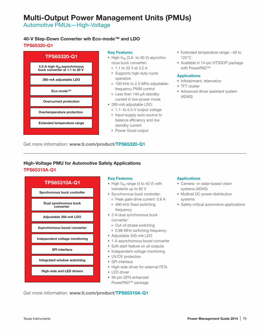
Texas Instruments Power Management Guide 2014 | 79
Multi-Output Power Management Units (PMUs)Automotive PMUs—High-Voltage
40-V Step-Down Converter wih Eco-mode™ and LDOTPS65320-Q1
Get more information: www.ti.com/product/TPS65320-Q1
High-Voltage PMU for Automotive Safety ApplicationsTPS65310A-Q1
Key Features• High VIN range (4 to 40 V) with
transients up to 60 V• Synchronous buck controller:
Peak gate-drive current: 0.6 A490-kHz fixed switching frequency
• 2-A dual synchronous buck converter:
Out-of-phase switching0.98-MHz switching frequency
• Adjustable 350-mA LDO• 1-A asynchronous boost converter• Soft-start feature on all outputs• Independent voltage monitoring• UV/OV protection• SPI interface• High-side driver for external FETs• LED driver• 56-pin QFN enhanced
PowerPAD™ package
Get more information: www.ti.com/product/TPS65310A-Q1
Key Features• High-VIN (3.6- to 40-V) asynchro-
nous buck converter:1.1 to 20 V at 3.2 ASupports high-duty-cycle operation100-kHz to 2.5-MHz adjustable-frequency PWM controlLess than 140-µA standby current in low-power mode
• 280-mA adjustable LDO:1.1- to 5.5-V output voltageInput-supply auto-source to balance efficiency and low standby currentPower Good output
TPS65320-Q1
3.2-A high-VIN asynchronousbuck converter at 1.1 to 20 V
Extended temperature range
280-mA adjustable LDO
Overcurrent protection
Overtemperature protection
Eco-mode™
TPS65310A-Q1
SPI interface
Dual synchronous buckconverter
Asynchronous boost converter
Independent voltage monitoring
Adjustable 350-mA LDO
Synchronous buck controller
Integrated window watchdog
High-side and LED drivers
• Extended temperature range: –40 to 125°C
• Available in 14-pin HTSSOP package with PowerPAD™
Applications• Infotainment, telematics• TFT cluster• Advanced driver assistant system
(ADAS)
Applications• Camera- or radar-based vision
systems (ADAS)• Multirail DC power-distribution
systems• Safety-critical automotive applications

80 | Power Management Guide 2014 Texas Instruments
Multi-Output Power Management Units (PMUs)Automotive PMUs—Low-Voltage
Integrated PMU with Three DC/DC Converters and Eight LDOsTPS659119-Q1
Get more information: www.ti.com/product/TPS659119-Q1
2.25-MHz Step-Down Converter with Dual LDOs and SVSTPS65000-Q1The TPS65000 was introduced several years ago as a general-purpose LDO for consumer products. It has been requalified to enable the same flexibility in automotive products.
Get more information: www.ti.com/product/TPS65000-Q1
Key Features• VIN range from 2.7 to 5.5 V• Four adjustable step-down
converters:Two 0.8- to 1.65-V at 1.8 A for DVFSOne 0.9- to 3.4-V at 1 A for I/OOne 1.2- to 3.4-V at 1.8 A for DDRx memory
• Two microprocessor DC/DC converters for RTC supply
• 200-mA LDO at 0.9- to 3.3-V adjustable output
• Three load switches support:DDR3 self-refresh modeUSB port9-V auxiliary power port
• Precision output-voltage monitor-ing for compatibility with SA335x
• Automatic power-up/down sequencing• Extended temperature range of –40 to
125°C• I2C interface• 6 x 6-mm QFN or 9 x 9-mm HTQFP
package
Applications• Infotainment• Advanced driver assistant system
(ADAS)• Instrument cluster
Key Features• 0.6-A step-down converter:
VIN range from 2.3 to 6 VSpread-spectrum clock (SSC) generation for reduced EMI2.25-MHz fixed-frequency operation
• Two 0.3-A adjustable LDOs:VIN range from 1.6 to 6 VSeparate power inputs and enables
• AEC-Q100 qualified:Device temperature grade 2: –40 to 105°CDevice HBM ESD classification level H2Device CDM ESD classification level C4B
• 3 x 3-mm 16-pin QFN package
Applications• Point of load• Embedded processor power• Portable media
TPS659119-Q1
Two buck converters with DVS
Buck converter for I/O power
Embedded power controller
Eight LDOs and one RTC LDO
High-speed I2C interface
RTC resource
Nine configurable GPIOs
32-kHz clock output
TPS65000-Q1
0.6-A buck converter
Spread-spectrum clockgeneration
2.25-MHz fixed frequency
Two 0.3-A adjustable LDOs
Separate power inputsand enables
3 x 3-mm QFN
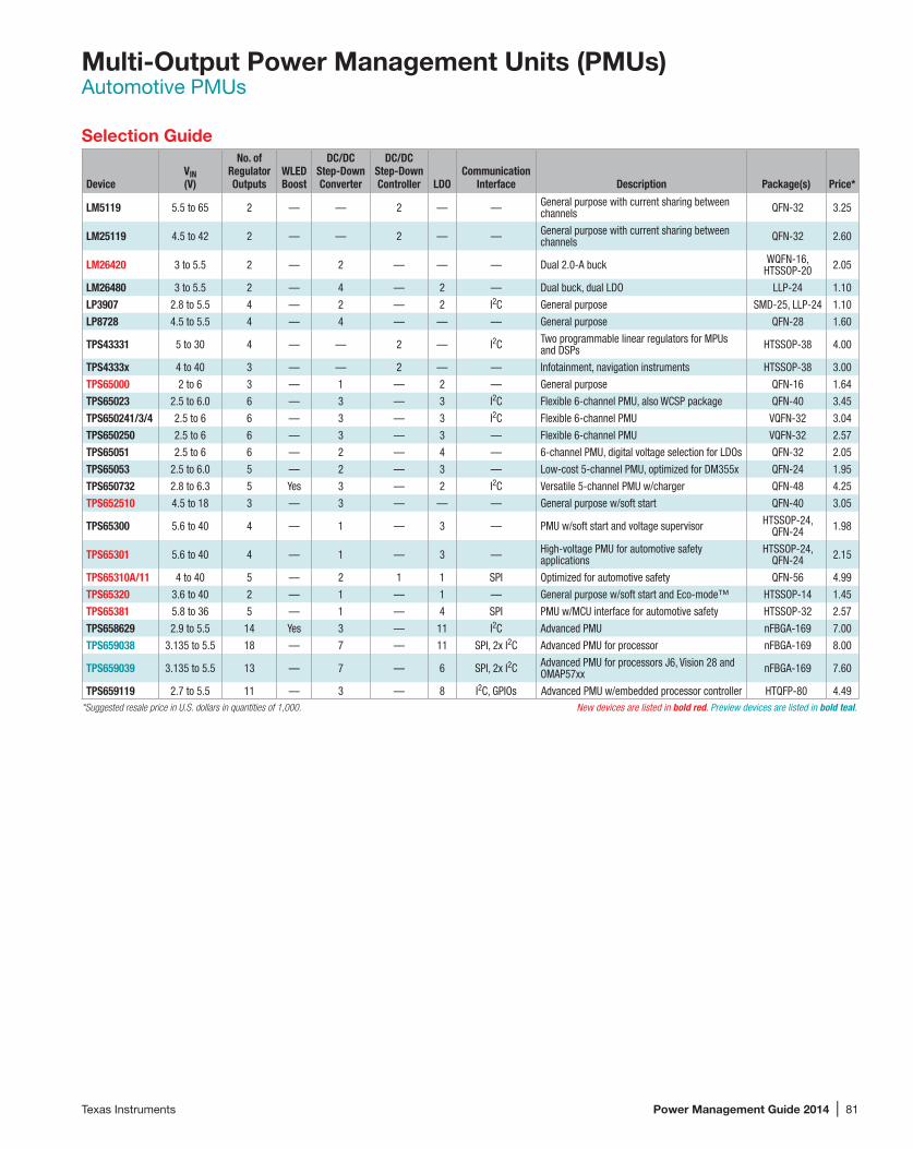
Texas Instruments Power Management Guide 2014 | 81
Multi-Output Power Management Units (PMUs)Automotive PMUs
Selection Guide
DeviceVIN (V)
No. of Regulator Outputs
WLED Boost
DC/DC Step-Down Converter
DC/DC Step-Down Controller LDO
Communication Interface Description Package(s) Price*
LM5119 5.5 to 65 2 — — 2 — — General purpose with current sharing between channels QFN-32 3.25
LM25119 4.5 to 42 2 — — 2 — — General purpose with current sharing between channels QFN-32 2.60
LM26420 3 to 5.5 2 — 2 — — — Dual 2.0-A buck WQFN-16, HTSSOP-20 2.05
LM26480 3 to 5.5 2 — 4 — 2 — Dual buck, dual LDO LLP-24 1.10
LP3907 2.8 to 5.5 4 — 2 — 2 I2C General purpose SMD-25, LLP-24 1.10
LP8728 4.5 to 5.5 4 — 4 — — — General purpose QFN-28 1.60
TPS43331 5 to 30 4 — — 2 — I2C Two programmable linear regulators for MPUs and DSPs HTSSOP-38 4.00
TPS4333x 4 to 40 3 — — 2 — — Infotainment, navigation instruments HTSSOP-38 3.00
TPS65000 2 to 6 3 — 1 — 2 — General purpose QFN-16 1.64
TPS65023 2.5 to 6.0 6 — 3 — 3 I2C Flexible 6-channel PMU, also WCSP package QFN-40 3.45
TPS650241/3/4 2.5 to 6 6 — 3 — 3 I2C Flexible 6-channel PMU VQFN-32 3.04
TPS650250 2.5 to 6 6 — 3 — 3 — Flexible 6-channel PMU VQFN-32 2.57
TPS65051 2.5 to 6 6 — 2 — 4 — 6-channel PMU, digital voltage selection for LDOs QFN-32 2.05
TPS65053 2.5 to 6.0 5 — 2 — 3 — Low-cost 5-channel PMU, optimized for DM355x QFN-24 1.95
TPS650732 2.8 to 6.3 5 Yes 3 — 2 I2C Versatile 5-channel PMU w/charger QFN-48 4.25
TPS652510 4.5 to 18 3 — 3 — — — General purpose w/soft start QFN-40 3.05
TPS65300 5.6 to 40 4 — 1 — 3 — PMU w/soft start and voltage supervisor HTSSOP-24, QFN-24 1.98
TPS65301 5.6 to 40 4 — 1 — 3 — High-voltage PMU for automotive safety applications
HTSSOP-24, QFN-24 2.15
TPS65310A/11 4 to 40 5 — 2 1 1 SPI Optimized for automotive safety QFN-56 4.99
TPS65320 3.6 to 40 2 — 1 — 1 — General purpose w/soft start and Eco-mode™ HTSSOP-14 1.45
TPS65381 5.8 to 36 5 — 1 — 4 SPI PMU w/MCU interface for automotive safety HTSSOP-32 2.57
TPS658629 2.9 to 5.5 14 Yes 3 — 11 I2C Advanced PMU nFBGA-169 7.00
TPS659038 3.135 to 5.5 18 — 7 — 11 SPI, 2x I2C Advanced PMU for processor nFBGA-169 8.00
TPS659039 3.135 to 5.5 13 — 7 — 6 SPI, 2x I2C Advanced PMU for processors J6, Vision 28 and OMAP57xx nFBGA-169 7.60
TPS659119 2.7 to 5.5 11 — 3 — 8 I2C, GPIOs Advanced PMU w/embedded processor controller HTQFP-80 4.49*Suggested resale price in U.S. dollars in quantities of 1,000. New devices are listed in bold red. Preview devices are listed in bold teal.

82 | Power Management Guide 2014 Texas Instruments
Multi-Output Power Management Units (PMUs)Special Function PMUs
PMU for Baseband and RF-PA PowerTPS657120
Get more information: www.ti.com/product/TPS657120
Key Features• VIN range from 2.8 to 5.5 V• Three step-down converters for
RF transceiver power• Dynamic voltage scaling• Two low-noise RF LDOs with 1.2-
to 3.4-V output-voltage range• 16- to 26-µA quiescent current for
converters, 32-µA for LDOs• Bypass switch for powering
RF-PA• Eco-mode™• Two GPIOs with 1-mA sink
capability• 26-MHz MIPI® RFFE interface• Flexible power-up/down
sequencing
Applications• Data cards• Smartphones
TPS657120
Two 0.25/0.3-A fixed-voltagebuck converters and
2-A adjustable buck converter
Two 10-mA adjustablelow-noise RF LDOs
MIPI® RFFE interface
Eco-mode™
Two GPIOs
Selection Guide
DeviceVIN (V) No
. of R
egul
ator
Ou
tput
s
Char
ger
WLE
D Bo
ost
DC/D
C St
ep-D
own
Conv
erte
r
LDO
DC/D
C St
ep-U
p Co
nver
ter
Com
mun
icat
ion
Inte
rface
Description Package(s) Price*
LM10502 2.5 to 5.5 3 — — 2 1 — SPI PMU for SSD memory Micro SMD-34 0.90
LP3910 2.5 to 6 5 Linear — 2 2 1 I2C PMU for HDD-based media player WQFN-48 2.11
LP3913 2.5 to 6 5 Linear — 3 2 — I2C PMU for flash-based media player WQFN-48 2.11
LP3918 3 to 5.5 7 Linear — — 7 — I2C Battery charge management PMU DSBGA-25 0.53
LP3921 3 to 5.5 7 Linear — — 7 — I2C Battery management PMU for audio amp WQFN-32 0.90
LP3923 3 to 5.5 8 Linear — — 8 — I2C Cell phone PMU DSBGA-30 0.60
LP3925 2.5 to 4.5 18 Linear — 3 15 — I2C High-performance PMU for handsets w/USB 2.0 DSBGA-30 1.40
LP3927 3 to 5.5 5 — — — 5 — — PMU for cellular/handsets WQFN-28 2.16
TPS40490 6 to 60 1 Switch — 1 — — — Buck controller configured for GaN/Si FETs QFN-28 6.00
TPS65030 2.5 to 6 1 — — — 1 — — Three charge pumps for USB OTG 25-ball chip scale 2.75
TPS65090 5.0 to 17.0 5 Switch — 3 2 — I2C Front-end PMU for two to three Li-Ion in series QFN-100 4.95
TPS65200 2.5 to 6.5 0 Switch Yes — — — I2C Front-end PMU with charger+WLED WCSP, QFN 2.45
TPS65233 4.5 to 20 2 — — — 1 1 I2C LNB voltage regulator for satellites QFN-16 0.90
TPS65290 2.5 to 5.5 2 — — 1 1 — I2C Meters, energy harvesting, +10-year battery QFN-24 1.75
TPS65471 2.7 to 5.75 5 Linear Yes — 4 1 — PMU for handheld devices QFN-40 2.25
TPS65510 2.7 to 5.5 5 — — — 4 1 — Battery-backup IC QFN-16 1.50
TPS65530/30A 1.5 to 5.5 9 — — 7 1 1 — PMU for digital still cameras QFN-48 3.90
TPS657120 2.8 to 5.5 — — — 3 2 — MIPI® RFFE, 2x GPIO PMU for baseband and RF-PA power WCSP-30 1.95
TPS65735/x835 2.5 to 6.4 2 Linear — — 1 — — 3D glasses, x835 with MSP430™ QFN-40 1.25
TPS658310 3.0 to 6.0 0 Switch Yes — — — I2C Front-end PMU with charger+flash+WLED WCSP-49 3.45*Suggested resale price in U.S. dollars in quantities of 1,000. New devices are listed in bold red.

Texas Instruments Power Management Guide 2014 | 83
Multi-Output Power Management Units (PMUs)Processor Attachment PMUs
Selection Guide
DeviceVIN (V) No
. of R
egul
ator
Ou
tput
s
Char
ger
Audi
o Co
dec
USB
2.0
OTG
Tr
ansc
eive
r
WLE
D Bo
ost
DC/D
C St
ep-D
own
Conv
erte
r
DC/D
C St
ep-D
own
Cont
rolle
r
LDO
Com
mun
icat
ion
Inte
rface
Description Package(s) Price*
ARM® Cortex™-R4TPS65381-Q1 5.8 to 36 5 — — — — 1 — 4 SPI Safety-critical applications HTSSOP-32 2.57
ARM Cortex A8 PMUsLP3925 4.5 to 6.5 18 Linear — — Yes 3 — 15 I2C Smartphone PMU Micro SMD-81 1.40
LP3974 4.5 to 6.5 20 Linear — — — 4 — 16 I2C Smartphone PMU Micro SMD-100 2.46
TPS65023x 2.5 to 6.0 6 — — — — 3 — 3 I2C Flexible 6-channel PMU, also WCSP package QFN-40 2.95
TPS65024x 2.5 to 6 6 — — — — 3 — 3 I2C Flexible 6-channel PMU VQFN-32 2.60
TPS650250 2.5 to 6.0 6 — — — — 3 — 3 — Flexible PMU with adjustable VOUT, optimized for AM335x QFN-32 2.20
TPS65053 2.5 to 6.0 5 — — — — 2 — 3 — Low-cost 5-channel PMU, optimized for DM355x QFN-24 1.95
TPS65070/2/3x 2.8 to 6.3 5 Linear — — Yes 3 — 2 I2C With and without touch-screen controller, Jacinto 3 QFN-48 3.60
TPS65217x 2.7 to 6.5 7 Linear — — Yes 3 — 4 — Optimized for AM335x processors QFN-48 3.45
TPS65910x 2.7 to 5.5 13 — — — — 3 — 9 2x I2C Flexible PMU with 5-V boost QFN-48 3.30
TPS65921 2.7 to 4.5 7 — — Yes — 3 — 4 2x I2C Optimized for OMAP™35x processors BGA-139 3.20
TPS65930 2.7 to 4.5 7 — Yes Yes — 3 — 4 2x I2C Optimized for OMAP35x processors BGA-139 3.80
TPS65950 2.7 to 4.5 13 Linear Yes Yes — 3 — 10 2x I2C Optimized for OMAP35x processors BGA-209 4.40
TPS65951 2.7 to 4.5 13 — Yes Yes — 3 — 10 2x I2C Optimized for OMAP35x, 0.8-mm pitch BGA-169 4.40
ARM Cortex A9 PMUsTPS65862x/4x 4.3 to 6.5 14 Linear — — Yes 3 — 11 I2C Optimized for Tegra® 2 BGA-121 5.95
TPS659110/2/3/9 2.7 to 5.5 13 — — — — 3 1 9 2x I2C With DC/DC controller up to 10 A, TPS659119 optimized for Jacinto 4/5 and Tegra 3 BGA-98 3.75
TPS65912x 2.3 to 5.5 14 — — — — 4 — 10 I2C/SPI Flexible PMU with four DC/DC converters WCSP-81 4.95
TWL6030/32/40/41 2.3 to 5.5 18 Switch Yes — — 7 — 11 2x I2C OMAP 4 power and audio FBGA + PBGA 4.30
ARM Cortex A15 PMUsTPS659038EP-Q1 3.15 to 5.5 12 — — — — 7 — 5 2x I2C Cortex A15 processors, OMAP54xx nFBGA, mrQFN-st 8.00
TPS659039-Q1 3.135 to 5.5 13 — — — — 7 — 6 SPI, 2x I2C Advanced PMU for processors J6, Vision 28 and OMAP57xx nFBGA-169 7.60
TPS65913 2.3 to 5.5 18 — — — 1 6 — 11 2x I2C Cortex A15 processors WCSP, mrQFN TBD
TWL6040/41 2.3 to 5.5 18 — — — 1 6 — 11 2x I2C OMAP 5 power and audio WCSP, mrQFN 1.70/1.50*Suggested resale price in U.S. dollars in quantities of 1,000. New devices are listed in bold red. Preview devices are listed in bold teal.

84 | Power Management Guide 2014 Texas Instruments
Multi-Output Power Management Units (PMUs)General Purpose PMUs
Selection Guide
DeviceVIN (V) No
. of R
egul
ator
Ou
tput
s
Char
ger
WLE
D Bo
ost
DC/D
C St
ep-D
own
Conv
erte
r
LDO
Load
Sw
itche
s
Com
mun
icat
ion
Inte
rface
Description Package(s) Price*
LM10503 3 to 5.5 3 — — 3 — — PWI™ Ideal for ASIC and SOC designs WQFN-36 3.75
LM10504/6 3 to 5.5 4 — — 3 1 — SPI Ideal for flash and SSDs DSBGA-34 1.20
LM10524 3 to 5.5 3 — — 3 — — SPI Ideal for flash and SSDs SMD-46 2.15
LM26400Y 3.0 to 20.0 2 — — 2 — — — Dual buck LLP-16 2.10
LM26420 3 to 5.5 2 — — 2 — — — Dual 2.0-A buck WQFN-16, HTSSOP-20 2.05
LM26480 2.8 to 5.5 4 — — 2 2 — — General purpose LLP-24 0.95
LM26484 3 to 5.5 3 — — 2 1 — — General purpose WQFN-24 0.70
LM3280 2.7 to 5.5 4 — — 1 3 — — Battery-powered RF SMD-16 0.65
LM3686 2.7 to 5.5 3 — — 1 2 — — Low-power PMU DSBGA-12 0.40
LM3687 2.7 to 5.5 3 — — 1 1 — — Low-power PMU DSBGA-9 0.40
LP3905 3 to 5.5 4 — — 2 2 — — General purpose WSON-14 1.17
LP3906 2.7 to 5.5 4 — — 2 2 — I2C General purpose WQFN-24 1.17
LP3907 2.8 to 5.5 4 — — 2 2 — I2C General purpose DSBGA-25, WQFN-24 0.95
LP3910 2.7 to 5.5 5 Linear — 3 2 — I2C Portable with buck-boost LLP-48 2.11
LP3971/2 2.7 to 5.5 9 Backup — 3 6 — I2C PMU for advanced applications processors WQFN-40 3.25
LP3974 2.7 to 5.5 15 Linear — 4 11 — I2C PMU for advanced applications processors Micro SMD-100 2.46
LP8720 2.7 to 4.5 6 — — 1 5 — I2C General purpose DSBGA-20 0.70
LP8725 2.6 to 4.5 9 — — 2 7 — I2C General purpose DSBGA-30 1.29
TPS6500x 1.8 to 6.0 3 — — 1 2 — — General purpose QFN-16 1.40
TPS6501x 4.5 to 5.5 4 Linear 2 2 — I2C General purpose QFN-48 2.55
TPS65050/1/2/4/6 2.5 to 6.0 6 — — 2 4 — Logic H/L Low-cost 6-channel PMU QFN-32 1.75
TPS65053/8 2.5 to 6.0 5 — — 2 3 — — Low-cost 5-channel PMU QFN-24 1.65
TPS65250/1 4.5 to 18.0 3 — — 3 — — — General purpose QFN-40 3.05
TPS65252 4.5 to 16.0 2 — — 2 — 1 — General purpose w/USB switch QFN-28 1.95
TPS65253 4.5 to 16.0 2 — — 2 — — — General purpose w/integrated FETs QFN-28 2.95
TPS65257/8 4.5 to 16 3 — — 3 — 2 — With 1/2 USB switches QFN-40 3.25
TPS65261 4.5 to 18 3 — — — 3 — — General purpose triple buck converter QFN-32 1.90
TPS65262 4.5 to 18 5 — — 3 2 — — Triple buck converters with dual LDO QFN 2.20
TPS65270 4.5 to 16.0 2 — — 2 — — — General purpose (3 A, 2 A), ideal for two layers QFN-28 1.25
TPS65273V/6V/9V 4.5 to 18 2 — — 2 — — I2C General purpose w/diff. current ratings HTSSOP-32, QFN-36 2.95
TPS65280/1/2 4.5 to 18.0 1 — — 1 — 2 — With one to two power switches QFN-24 1.95
TPS65287 4.4 to 18 4 — — 3 — 1 — Triple output buck with integrated USB high-power switch QFN-40 2.45
TPS65288 4.5 to 18 5 — — 3 — 2 — Triple buck converters with two high-power switches QFN-40 2.45
TPS65580/1 4.5 to 18 3 — — 3 — — — Advanced D-CAP2™ HTSSOP-20 0.65
TPS657051/2 3.3 to 6 3 — — 2 1 — — PMU for embedded cameras WCSP-16 1.20
TPS65708 3.6 to 6 4 — — 2 2 — — PMU for embedded cameras WCSP-16 1.65
TPS65720/1 4.3 to 28.0 2 Linear — 1 1 — I2C Smallest single-Li-Ion applications WCSP-25, QFN 1.65
TPS65800/10/11/20 4.3 to 16 11 Linear Yes 2 7 — I2C, three GPIOs Advanced PMU w/ LED drivers QFN-56 5.75*Suggested resale price in U.S. dollars in quantities of 1,000. New devices are listed in bold red.

Texas Instruments Power Management Guide 2014 | 85
Multi-Output Power Management Units (PMUs)Embedded Processor Support
Reference designs for these TI processor families are avail-able online. Bookmark these pages to find new designs for the latest DSP and microprocessor generations.
PMU solutions with and without battery charger: www.ti.com/pmu
TI power-management reference designs: www.ti.com/processorpower
Processor Part Number PMU
TI C2834x TPS65000, TPS650061, TPS65300/301-Q1
TI C55x TPS65000x
TI C6742/6/8 TPS65910, TPS65070, TPS65023-Q1
TI C6745/7 TPS65910, TPS65023
TI C6A814x TPS659113
TI C6A816x TPS659112
TI DM335, DM355, DM365, DM367 TPS65053, TPS65070/73
TI DM368 TPS650532, TPS65023
TI DM385 TPS659113
TI DM37x 800MHz TPS6595x/30/2x/10, TPS65023, TPS650731
TI DM37x 1GHz TPS65950A3/x51/x21B1/x10, TPS65023, TPS650731
TI DM643x, DM644x TPS65023-Q1, TPS659105
TI DM812x/ DM814x TPS659113
TI DM816x TPS659112
TI AM17x TPS65910, TPS65000x, TPS650061, TPS65023-Q1
TI AM18x TPS65910, TPS65000x, TPS650061, TPS65070/73
TI AM335x TPS65910A/A3, TPS65217/8, TPS650250-Q1
TI AM35x TPS65910, TPS650732-Q1, TPS65023-Q1
TI AM37x 800MHz TPS6595x/30/2x/10, TPS65023-Q1, TPS650731
TI AM37x 1GHz TPS65950A3/x51/x21B1/x10, TPS65023, TPS650731
TI AM387x TPS659113
TI AM389x TPS659112
TI RM4x, TMS570 TPS65300/301-Q1, TPS6531x-Q1, TPS65381-Q1
TI OMAP™3503/15/25/30 TPS6595x/30/2x/10, TPS65073x, TPS65023-Q1
TI OMAP3611/21/30 TPS6595x/30/2x/10, TPS65023
TI OMAP-L132, L137, L138 TPS65910, TPS65023, TPS650061, TPS65070
TI OMAP4430/60/70 TWL6030/32, TWL6040/41 TPS659119-Q1
TI OMAP543x TWL6040/41, TPS659038-Q1
TI Jacinto 3 (DRA5xx) TPS650732-Q1
TI Jacinto 4 (DRA64x) TPS659119-Q1
TI Jacinto 5 (DRA62x/65x) TPS659119-Q1
TI Jacinto 6 (DRA72x/74x) TPS659038-Q1
Processor Part Number PMU
Altair 3100/6200 TPS659122
Ambarella iOne Please ask TI
Freescale IMX25 TPS65051/2
Freescale IMX27 TPS65053-Q1, TPS659107
Freescale IMX35/37 TPS650250-Q1, TPS659107
Freescale IMX508 TPS659108
Freescale IMX51 TPS659109
Freescale IMX53 TPS659106
Freescale IMX6x Please ask TI
Freescale1 Qorivva (57xx) TPS65381-Q1
Freescale1 Qorivva (576x) TPS65381-Q1
Infineon1 Aurix (TC27x) TPS65381-Q1
Marvell PXA270 TPS65021/2
Marvell Armada Please ask TI
Nvidia Tegra 2 TPS658621/2/3, TPS658640/3, TPS658629-Q1
Nvidia Tegra 3 TPS659110/9, TPS659119-Q1
Nvidia Tegra 4 TPS65913
Nvidia Tegra 4 (SP30) TPS65712x, LP8755
Nvidia i450, i500 TPS659121
Renesas1 RH850/V850 TPS65381-Q1
Rockchip RK29 TPS659102
Rockchip RK30 TPS659102
Samsung S5PV210, S5PC110 TPS659101
Samsung S5PC100 TPS659103, LP3974
Samsung S5P6440 TPS659104
Samsung S5PV310 Please ask TI
Samsung Exynos 4210 Please ask TI
STM SPEAr 300 TPS650532
STM SPEAr 1310 Please ask TI1Automotive-only processor.
Embedded Processors Supported by TI Power Management Units (PMUs)
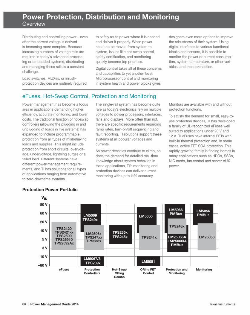
86 | Power Management Guide 2014 Texas Instruments
Power Protection, Distribution and MonitoringOverview
Distributing and controlling power—even after the correct voltage is derived—is becoming more complex. Because increasing numbers of voltage rails are required in today’s advanced process-ing or embedded systems, distributing and managing these rails is a constant challenge.
Load switches, MUXes, or inrush- protection devices are routinely required
to safely route power where it is needed and deliver it properly. When power needs to be moved from system to system, issues like hot-swap control, safety certification, and monitoring quickly become top priorities.
Digital control takes all of these concerns and capabilities to yet another level. Microprocessor control and monitoring in system health and power blocks gives
designers even more options to improve the robustness of their system. Using digital interfaces to various functional blocks and sensors, it is possible to monitor the power or current consump-tion, system temperature, or other vari-ables, and then take action.
eFuses, Hot-Swap Control, Protection and Monitoring
80 V
60 V
20 V
10 V
5 V
3 V
–10 V
–80 V
VIN
eFuses ProtectionControllers
Hot-SwapORingCombo
ORing FET Control
Protection andMonitoring
LM5069TPS249x
LM5067/8TPS239x
TPS235xTPS245x
LM5050
LM5066PMBus
LM25066ALM25066IA
PMBus
LM5051
LM2506xTPS247xxTPS233x
LM25056
Monitoring
LM5056PMBus
TPS2420TPS2421-xTPS2590
TPS25910TPS2592Ax
TPS241x
TPS248x
Protection Power Portfolio
Power management has become a focus area in applications demanding higher efficiency, accurate monitoring, and lower costs. The traditional function of hot-swap controllers (allowing the plugging in and unplugging of loads in live systems) has expanded to include programmable pro tection from all types of misbehaving loads and supplies. This might include protection from short circuits, overvolt-age, undervoltage, lightning surges or a failed load. Different systems have different power-management require-ments, and TI has solutions for all types of applications ranging from automotive to zero-downtime systems.
The single-rail system has become quite rare as today’s electronics rely on multiple voltages to power processors, interfaces, fans and displays. More often than not, there are specific requirements regarding ramp rates, turn-on/off sequencing and fault reporting. TI solutions support these systems at all popular voltages and currents.
As power densities continue to climb, so does the demand for detailed real-time knowledge about system behavior. In these applications, TI’s monitoring and protection devices can deliver current monitoring with up to ½% accuracy.
Monitors are available with and without protection functions.
To satisfy the demand for small, easy-to-use protection devices, TI has developed a family of UL-recognized eFuses well suited to applications under 20 V and 12 A. TI eFuses have internal FETs with built-in thermal protection and, in some cases, active FET SOA protection. This rapidly growing family is finding homes in many applications such as HDDs, SSDs, NIC cards, fan control and server AUX power.

Texas Instruments Power Management Guide 2014 | 87
Power Protection, Distribution and MonitoringeFuses, Hot-Swap Control, Protection and Monitoring
System Power Management and Protection IC with PMBusLM25066, LM25066I, LM25066ATI’s PMBus-enabled system protection and management products combine hot swap control with embedded telemetry measurement, intelligence, and digital communica-tions which enable them to deliver accurate power usage data back to the system to optimize power consumption, reduce operating expenses, and increase reliability
LM25066/I/A
VSYS VOUT
PowerGood
GND
UVLO
SCL
PWRGNDTIMER
PGD
OUTVIN SENSE GATE
SMBusInterface SDA
SMBA
ADR0ADR1ADR2
AUX
D+
VDD
OVLO
VAUX
FB V PG
RETRY
CLCB
VREF
Typical application circuit.
Key Features• Intel Node Manager 2.0 compliant• Hot swap with current and power
limiting• Adjustable current limit, circuit breaker
thresholds• Measure voltage, current, power and
temperature• Simultaneous sampling of current and
voltage for true power measurement• Peak and programmable average
power capture• Dynamic configuration of fault and
warning levels• I2C/SMBus interface with PMBus
compliance
Applications• Server backplane systems• Base station power distribution systems• Solid-state circuit breakers
Get more information: www.ti.com/product/LM25066
eFuse (Integrated FET) Selection Guide
Device Description Chan
nels
VIN (min)(V) V a
bsm
ax_c
ont
(V)
Current-Limit Threshold (typ)
(A)Fault
Response R ON
(mΩ
)
ON_OFF Control Input(s)
Status Output Package(s) Price*
TPS2420 3- to 20-V, 2- to 5-A eFuse with load current monitoring 1 2.9 to 20 25 1 to 5 Prog 30 EN\ FLT, IMON,
PG 16 QFN 1.38
TPS2421-1/2 3- to 20-V, 2- to 5-A eFuse 1 2.9 to 20 25 1 to 5 Latch/Retry 33 EN\ FLT, PG 8SO PowerPAD™ 1.06
TPS24750/1 2.5- to 18-V, 12-A eFuse, current limit at startup only 1 2.5 to 18 30 Adjustable Latch/Retry 3 ENUV FLT, IMON,
PG\ 36 VQFN 1.80
TPS2590 3- to 20-V, 0- to 6.5-A eFuse 1 2.9 to 20 25 1 to 5 Prog 30 EN\ FLT 16 QFN 0.90
TPS25910 3- to 20-V, 2- to 6.5-A eFuse with dV/dt control 1 2.9 to 20 22 0.8 to 6.5 Auto Retry 30 EN\ FLT 16 QFN 0.90
TPS2592AL/AA 12-V, 2- to 5-A eFuse/surge clamp with block FET driver 1 4.5 to 13.8 20 2 to 5 Latch/Retry 28 ENUV — 10 SON 0.55
TPS2592BA/BL 5-V, 2- to 5-A eFuse/surge clamp with block FET driver 1 4.5 to 5.5 20 2 to 5 Latch/Retry 28 ENUV — 10 SON 0.55
TPS2592ZA 19-V, 2- to 5-A eFuse with block FET driver 1 4.5 to 19 20 2 to 5 Auto Retry 28 ENUV — 10 SON 0.55
UCC2912 3- to 8-V , 0- to 3-A single hot-swap IC high-side MOSFET 1 3 to 8 8 IFAULT +1 or 4 A Auto Retry 150 SHTDWN\ FLT\ 16 SOIC,
24 TSSOP 3.25
UCC2915 7- to 15-V, 0- to 3-A high-side MOSFET, 100-µA IQ 1 7 to 15 15.5 IFAULT +1 or 4 A Auto Retry 150 SHTDWN\ FLT\ 16 SOIC 5.00
UCC3912 3- to 8-V, 0- to 3-A single hot-swap IC high-side MOSFET 1 3 to 8 8 IFAULT +1 or 4 A Auto Retry 150 SHTDWN\ FLT\ 16 SOIC,
24 TSSOP 2.30
UCC3915 0- to 3-A, 7- to 15-V high-side MOSFET, 100-µA IQ 1 7 to 15 15.5 IFAULT +1 or 4 A Auto Retry 150 SHTDWN\ FLT\ 16 SOIC,
24 TSSOP 2.55
UCC3916 4- to 6-V, 1.65-A high-side MOSFET for SCSI 1 4 to 6 6 2 Auto Retry 220 SHTDWN\ FLT 8 SOIC 2.55
UCC3918 3- to 6-V, 0- to 4-A low RON high-side protection 1 3 to 6 8 0.5 to 5 Auto Retry 75 SHTDWN\ FLT\ 16 SOIC 2.35
TPS2556/7 2.5- to 6.5-V, 0.5- to 5-A precision limit eFuse 1 2.5 to 6.5 7 0.5 to 5 Auto Retry 22 1L/1H FLT\ 8 QFN 0.90
TPS2560/A 2.5- to 6.5-V, 0.25- to 2.8-A dual precision limit eFuse 2 2.5 to 6.6 7 0.25 to 2.8 Auto Retry 44 2L FLT\ 10 QFN 0.90
TPS2561/A 2.5- to 6.5-V, 0.25- to 2.8-A dual precision limit eFuse 2 2.5 to 6.7 7 0.25 to 2.8 Auto Retry 44 2H FLT\ 10 QFN 0.90
*Suggested resale price in U.S. dollars in quantities of 1,000. New devices are listed in bold red.

88 | Power Management Guide 2014 Texas Instruments
Power Protection, Distribution and MonitoringeFuses, Hot-Swap Control, Protection and Monitoring
Hot Swap Controllers (External FET) Selection GuideFeatures1
Device Target Applications ChannelsVIN Range
(V)Enable/
Shutdown UV OV Fault PG LatchAuto Retry Ramp
PowerLimiting Package(s) Price*
TPS2300/01 CompactPCI®, general 2 3 to 13/3 to 5.5 1L/1H 4 4 4 4 Voltage No 20-pin TSSOP 1.60TPS2310/11 CompactPCI, general 2 3 to 13/3 to 5.5 1L/1H 4 4 4 4 Voltage No 20-pin TSSOP 1.60TPS2320/21 CompactPCI, general 2 3 to 13/3 to 5.5 1L/1H 4 4 4 4 Voltage No 16-pin SOIC/TSSOP 1.35TPS2330/31 CompactPCI, general 1 3 to 13 1L/1H 4 4 4 4 Voltage No 14-pin SOIC/TSSOP 1.25
TPS2342 CompactPCI, PCI-X®, PC-X2.0 12 3.3, Vaux, VIO, 5, +12, –12 1L 4 4 4 Voltage No 80-pin HTQFP 7.00
TPS2350 Full featured –48-V telecom, LS active ORing 2 –12 to –80 1H 4 4 4 4 4 Current No 14-pin SOIC/TSSOP 1.90TPS2358 xTCA mezzanine cards, general 12 V 2 8.5 to 17 2L 4 4 4 4 Current No 48-pin QFN 4.00TPS2359 xTCA mezzanine cards, general 12 V 2 8.5 to 17 1H/1L 4 4 4 4 S2 S2 Current No 36-pin QFN 5.00TPS2363 PCI Express® 6 3.3 Vaux, 3.3, +12 1L 4 4 4 4 Voltage No 48-pin QFP 2.50TPS2390 Simple –48-V telecom 1 –36 to –80 1H 4 4 Current No 8-pin MSOP 1.00TPS2391 Simple –48-V telecom 1 –36 to –80 1H 4 4 Current No 8-pin MSOP 1.00TPS2392 Full featured –48-V telecom 1 –20 to –80 1H 4 4 4 4 4 Current No 14-pin TSSOP 1.35TPS2393 Full featured –48-V telecom 1 –20 to –80 1H 4 4 4 4 4 Current No 14/44-pin TSSOP 1.35TPS2393A Full featured –48-V telecom (Fast retry) 1 –20 to –80 1H 4 4 4 4 4 Current No 14-pin TSSOP 1.35TPS2394 Full featured, ESD ruggedized –48-V hotswap 1 –12 to –80 1H 4 4 4 4 4 Current No 14-pin TSSOP 1.35TPS2398 Simple –48-V telecom with PG 1 –36 to –80 1H 4 4 Current No 8-pin MSOP 1.35TPS2399 Simple –48-V telecom with PG 1 –36 to –80 1H 4 4 Current No 8-pin MSOP 1.35TPS2400 Overvoltage/undervoltage protection IC 1 2 to 100 1H 4 4 4 — No 5-pin SOT-23 0.80TPS2456/A Inrush controller with reverse current control 2 8.5 to 15 2H 4 4 4 4 Current No 36-pin QFN 3.75TPS2458 xTCA mezzanine cards, general 12 V 1 8.5 to 15 1L 4 4 4 4 Current No 32-pin QFN 2.00TPS2459 xTCA mezzanine cards, general 12 V 1 8.5 to 15 1H/1L 4 4 4 4 S2 S2 Current No 32-pin QFN 2.50TPS24700 Industrial, mass storage, servers, telecom 1 2.5 to 18 1H 4 4 4 Current No 8-pin MSOP 1.10TPS24701 Industrial, mass storage, servers, telecom 1 2.5 to 18 1H 4 4 4 Current No 8-pin MSOP 1.10TPS24710 Industrial, mass storage, servers, telecom 1 2.5 to 18 1H 4 L L 4 Current Yes 10-pin MSOP 1.25TPS24711 Industrial, mass storage, servers, telecom 1 2.5 to 18 1H 4 L L 4 Current Yes 10-pin MSOP 1.25TPS24712 Industrial, mass storage, servers, telecom 1 2.5 to 18 1H 4 H H 4 Current Yes 10-pin MSOP 1.25TPS24713 Industrial, mass storage, servers, telecom 1 2.5 to 18 1H 4 H H 4 Current Yes 10-pin MSOP 1.25TPS24720 Industrial, mass storage, servers, telecom 1 2.5 to 18 1H 4 4 4 4 S2 S2 Current Yes 16-pin SON 1.40TPS2490 Servers, basestations, +48 V, +12 V 1 9 to 80 1H 4 4 4 Current Yes 10-pin MSOP 1.40TPS2491 Servers, basestations, +48 V, +12 V 1 9 to 80 1H 4 4 4 Current Yes 10-pin MSOP 1.40TPS2492 Servers, basestations, industrial, +48 V, +12 V 1 9 to 80 1H 4 4 4 4 4 Current Yes 14-pin TSSOP 1.45TPS2493 Servers, basestations, industrial, +48 V, +12 V 1 9 to 80 1H 4 4 4 4 4 Current Yes 14-pin TSSOP 1.45LM25069 12-V hotswap controller with power limiting 1 2.9 to 17 1H 4 4 4 H -1 -2 Current Yes 10-pin MSOP 1.19LM25061 12-V hotswap controller with power limiting 1 2.9 to 17 1H 4 4 H -1 -2 Current Yes 10-pin MSOP 1.33LM5060/Q Low Iq high-side protection controller 1 5.5 to 65 1H 4 4 4 L 4 Voltage No 10-pin MSOP 1.28/1.40LM5069 +48-V hotswap controller with power limiting 1 9 to 80 1H 4 4 4 H -1 -2 Current Yes 10-pin MSOP 1.35LM5068 Simple –48-V hotswap controller family 1 –10 to –90 1H 4 4 4 H/H/L/L -1/-3 -2/-4 Current No 8-pin MSOP 1.35LM5067 –48-V hotswap controller with power limiting 1 –9 to –80 1H 4 4 4 H -1 -2 Current Yes 10-pin MSOP/14-pin SOIC 1.50
1Pin function: L = active low, H = active high.2S = Selectable.`*Suggested resale price in U.S. dollars in quantities of 1,000.

Texas Instruments Power Management Guide 2014 | 89
Power Protection, Distribution and MonitoringeFuses, Hot-Swap Control, Protection and Monitoring
ORing Controllers Selection Guide
Device Description ChannelsVIN Range
(V)Enable/
Shutdown UV OV Fault PG
ORing Linear Gate
Drive
On/Off ORing
Function Package(s) Price*
TPS2410 ORing FET controller/MUX controller 1 0.8 to 16.5 1H 4 4 4 4 4 14-pin TSSOP 1.70
TPS2411 ORing FET controller/MUX controller 1 0.8 to 16.5 1H 4 14-pin TSSOP 1.70
TPS2412 ORing FET controller 1 0.8 to 16.5 48-pin SOIC,
8-pin TSSOP 1.20
TPS2413 ORing FET controller 1 0.8 to 16.5 48-pin SOIC,
8-pin TSSOP 1.20
TPS2419 ORing FET controller with OV/enable 1 3 to 16.5 1H 4 4 8-pin SOIC 1.20
LM5050-1 Positive HV ORing controller with AUX input 1 5 to 80 L 4 4 6-pin TSOT 1.25
LM5050-2 Positive HV ORing controller with FET test 1 6 to 80 L 4 4 4 6-pin TSOT 1.25
LM5051 Negative HV ORing controller with FET test 1 –6 to –100 L 4 4 4 8-pin SOIC 1.25
TPS2456/A Inrush/reverse current controller for dual sources 2 8.5 to 15 2H 4 4 4 4 36-pin QFN 3.45
TPS2358 Dual 12-V/3.3-V hotswap/ORing controller 2 8.5 to 15 2L 48-pin QFN 4.00
TPS2359 Dual 12-V/3.3-V hotswap/ORing controller 2 8.5 to 15 Via I2C 36-pin QFN 5.00*Suggested resale price in U.S. dollars in quantities of 1,000.
Protection and Monitoring with PMBus/I2C Selection Guide
DeviceVIN Range
(V)Enable/
Shutdown UV OV Fault PG LatchAuto Retry Interface
FET SOA Protection Package(s) Price*
LM25066/A 2.9 to 17 1H 4 4 4 4 Prog Prog I2C, SMBus, PMBus Yes 24-pin LLP 2.33/2.80
LM25066I/A 2.9 to 17 1H 4 4 4 4 Prog Prog I2C, SMBus, PMBus Yes 24-pin LLP 2.33/2.80
TPS2480/1 9 to 24 1H 4 4 Prog Prog I2C Yes 20-pin TSSOP 2.50
TPS2482/3 9 to 36 1H 4 4 Prog Prog I2C Yes 20-pin TSSOP 3.00
LM5066 10 to 80 1H 4 4 4 4 Prog Prog I2C, SMBus, PMBus Yes 28-pin eTSSOP 3.95
LM5064 –10 to –80 1H 4 4 4 4 Prog Prog I2C, SMBus, PMBus Yes 28-pin eTSSOP 3.45*Suggested resale price in U.S. dollars in quantities of 1,000.
Monitoring with PMBus/I2C Selection Guide
DeviceVIN Range
(V)Enable/
Shutdown Fault
Telemetry Data
Interface Package(s) Price*VIN IIN PIN Temp
LM25056/A 3 to 17 1H 4 4 4 4 4 I2C, SMBus, PMBus 24-pin LLP 1.50/1.70
LM5056 10 to 80 1H 4 4 4 4 4 I2C, SMBus, PMBus 28-pin TSSOP 2.49*Suggested resale price in U.S. dollars in quantities of 1,000.

90 | Power Management Guide 2014 Texas Instruments
Power Protection, Distribution and MonitoringCurrent-Limited and Non-Current-Limited Load Switches
>8 mm2
Needs design time and expertiseSlew-rate control will need R and C
91%Solution-Size
Reduction
Conventional SolutionTI’s TPS22901 Load Switch
ON
VIN VOUT
GND
>2.56 mm2
>2.56 mm2
0.5 mm21.28 mm2
1.28 mm2
0.64 mm2
Controlled slew rateReduced design time
ON GND
VIN VOUT
ON Resistance at V = 3.6 V (typical) (mΩ)IN
50 100 250 500
Num
ber
of
Cha
nnel
s
2
1
LM34904
500-mA current limit , r = 0.4 ΩPkg: 6 micro SMD
ON
LM34902
300-mA current limit , r = 0.6 ΩPkg: 6 micro SMD
ON
TPS22924C
Pkg: 6 CSP (0.5-mm pitch)rON = 5.7 mΩ, tr = 800 µs, QOD
TPS22906
TPS22904
TPS22903
TPS22929 (B/C)
TPS22951TPS22911A/13B
TPS22902B
bq2431x
TPS22946TPS22922B
TPS22902
TPS2552/3
TPS22941/3
TPS22960
TPS22922
TPS22901 TPS22942/4/5
TPS22949/A
TPS22921
Pkg: 4 CSP (0.5 -mm pitch)
Pkg: 4 CSP (0.4 -mm pitch)
Pkg: 4 CSP (0.4 -mm pitch)
Pkg: SC70
300-mA current limit , r = 1 ΩPkg: 6 CSP
ONPkg: 4 CSP (0.5-mm pitch)
Pkg: 4 CSP (0.4 -mm pitch)
Overvoltage/overcurrent protectionPkg: SON
30/70/155-mA current limit, shutdown and auto-restart, rON = 400 mΩ,
ultralow power (1 µA)Pkg: 6 CSP (0.5-mm pitch)
Pkg: 4 CSP (0.4- and 0.5-mm pitch)
Pkg: 4 CSP (0.4 -mm pitch)
USB, current-limited,7.5% current-limit accuracy
Pkgs: SON, SOT23
40-mA current limit, shutdownand auto-restart, r = 500 mΩ
Pkg: SC70ONPkg: 6 CSP (0.4- and 0.5-mm pitch)
Pkg: 4 CSP (0.4 -mm pitch)
Dual USB, current limited,10% current-limit accuracy
Pkg: SON
100-mA current limit, shutdownand auto-restart, r = 500 mΩ
Pkg: SC70ON
Integrated 100-mA current limit,low-noise LDO
Pkgs: 8 CSP/SON
Dual-channel, t = 75 or 660 µs,r = 435 mΩ
Pkgs: 8 SOT, µQFN
rON
Pkg: 6 CSP (0.4- and 0.5-mm pitch)
TPS2560/1
QOD = Quick output discharge
rON = 50 mΩ, tr = multiple options, QOD
rON = 14 mΩ, tr = 30 µs
rON = 14 mΩ, tr = 30 µs, QOD
rON = 14 mΩ, tr = 200 µs, QOD rON = 115 mΩ, tr = 100 µs or 4.5 ms
rON = 78 mΩ, tr = 40 µs, QOD
rON = 78 mΩ, tr = 40 µs
rON = 78 mΩ, tr = 220 µs, QOD
rON = 66 mΩ, tr = 1 µs
rON = 66 mΩ, tr = 1 µs, QOD
rON = 90 mΩ, tr = 220 µs, QODTPS22907
Pkg: 4 CSP (0.4-mm pitch)rON = 44 mΩ, tr = 1 µs
The Integration/Size Advantage of Load Switches
Portable Electronics Integrated Load Switches Product Portfolio

Texas Instruments Power Management Guide 2014 | 91
Power Protection, Distribution and MonitoringCurrent-Limited and Non-Current-Limited Load Switches
Selection Guide
DeviceInput Voltage
Range (V)Number of Channels
rON at 3.6 V(mΩ)
Output Rise Time (µs)
Quick Output Discharge
Max Output Current Enable Package(s) Price*
Non-Current-Limiting Load SwitchesTPS22901 1.0 to 3.6 1 78 40 No 500 mA Active high CSP (0.8x0.8 mm) 0.32TPS22902/B 1.0 to 3.6 1 78 40/220 Yes 500 mA Active high CSP (0.8x0.8 mm) 0.32TPS22903 1.1 to 3.6 1 66 1 No 500 mA Active high CSP (0.8x0.8 mm) 0.32TPS22906 1.0 to 3.6 1 90 220 Yes 500 mA Active high CSP (0.9x0.9 mm) 0.32TPS22907 1.1 to 3.6 1 44 36 No 1 A Active high CSP (0.9x0.9 mm) 0.38TPS22921 0.9 to 3.6 1 14 30 No 2 A Active high CSP (0.8x1.2 mm or 0.9x1.4 mm) 0.43TPS22922/B 0.9 to 3.6 1 14 30/200 Yes 2 A Active high CSP (0.8x1.2 mm or 0.9x1.4 mm) 0.43TPS22924B/C 0.75 to 3.6 1 18.3 100/800 Yes 2 A Active high CSP (0.9x1.4x0.4/0.5 mm) 0.28TPS22920 0.75 to 3.6 1 5.3 800 Yes 4 A Active high CSP, 0.9x1.9 mm 0.34TPS22966 0.8 to 5.5 2 15 Adj. Yes 6 A Active high SON-14, 3x2 mm 0.44
Non-Current-Limiting Load Switches with Reverse Current ProtectionTPS22910A 1.4 to 5.5 1 61 1 No 2 A Active low CSP (0.9x0.9x0.5 mm) 0.24TPS22913B 1.4 to 5.5 1 61 100 Yes 2 A Active high CSP (0.9x0.9x0.5 mm) 0.24TPS22913C 1.4 to 5.5 1 61 1000 Yes 2 A Active high CSP (0.9x0.9x0.5 mm) 0.24TPS22912C 1.4 to 5.5 1 61 1000 No 2 A Active high CSP (0.9x0.9x0.5 mm) 0.24TPS22929D 1.4 to 5.5 1 115 4000 Yes 2 A Active high SOT23-6 (3x3 mm) 0.24
DeviceInput Voltage
Range (V)rON at 1.8 V
(Ω)Current Limit
(mA)Current-Limit
Blanking Time (ms)Auto-Restart Time
(ms) Active Package(s) Price*
Current-Limiting Load SwitchesTPS22941 1.62 to 5.5 1.1 40 10 80 Low 5 SC70 0.42TPS22942 1.62 to 5.5 1.1 100 10 80 Low 5 SC70 0.42TPS22943 1.62 to 5.5 1.1 40 0 — High 5 SC70 0.42TPS22944 1.62 to 5.5 1.1 100 0 — High 5 SC70 0.42TPS22945 1.62 to 5.5 1.1 100 10 80 High 5 SC70 0.42TPS22946 1.62 to 5.5 0.6 155/70/30 10 70 High 6 CSP 0.55TPS22949/A 1.62 to 4.5 1 100 12 70 High 8 CSP/SON 0.70TPS22951 2.8 to 5.3 1 600 — — High 6 CSP 0.45LM34902/4 2.8 to 5.3 0.6/0.4 300/500 — — High micro SMD-6 0.29/0.33
*Suggested resale price in U.S. dollars in quantities of 1,000.
Input Voltage (V)
0.75 1.2 1.8 3.6 125.5
500
1000
50
100
10
ON
Res
ista
nce
(typ
) (mΩ
)
TPS22960Dual-channel, t = 75 or 660 µs, SOT23r
TPS22929 (B/D)
TPS22921/2/2B
TPS22932B500 mA, configurable logic, QOD,
6 CSP (0.4-mm pitch)
TPS22907
TPS22932B500 mA, configurable logic, QOD,
6 CSP (0.4-mm pitch)
TPS22911A/13B2 A, tr = 0.5 or 100 µs, QOD, RCB, 4 CSP (0.4-mm pitch)
TPS22901/2/2B/3/4/6500 mA, t =r 1, 30 or 220 µs,QOD, 4 CSP (0.4-mm pitch)
TPS22924C QOD = Quick output dischargeRCB = Reverse current blocking
2 A, tr = 100 µs or 4.5 ms, QOD, RCB, SOT23-6
1 A, tr = 30 µs, 4 CSP (0.5-mm pitch)
2 A, tr = 800 µs, QOD 6 CSP (0.5-mm pitch)
2 A, tr = 30 or 200 µs, QOD, 6 CSP (0.5-mm pitch)
Non-Current-Limited Load Switches Product Portfolio

92 | Power Management Guide 2014 Texas Instruments
Power Protection, Distribution and MonitoringPower-over-Ethernet (PoE)
The concept of providing power along with data is as old as basic telephone service, but the formal standard for pro viding power along Ethernet lines is much more recent. Though the original Power-over-Ethernet (PoE) specification was approved in 2005, the IEEE ratified a superseding standard in summer 2009—the IEEE 802.3at. Both stan-dards specify behavior for devices receiving power across Ethernet lines, known as powered devices (PDs), and methods for injecting power onto the line, used in equip-ment known as power sourcing equipment (PSE).
TPS23851 and TPS23752 maximize light-load efficiency using programmable synchronous rectifier shutoff and variable-frequency operation.
Original PoE . . . Only Better!The vast majority of PoE applications need less than 12.95 W. For this growing market area, TI has a large portfolio of options to consider.
TPS23753A• Simplest, most elegant, lowest-cost
solution for a standard PoE PD• Incorporates rugged tolerance for
extended ESD exposure• Auxiliary power supplies are fully
supported—down to 12 V
TPS23750• TI’s original PD front end plus DC/DC
converter• Supports simple, low-cost, non-isolated
buck-converter topologies with no transformer required
TI has a family of IEEE 802.3at compliant PoE solutions for all power levels, includ-ing those above 13 W.
Up to 350-ftCategory 5
Cable
RX
TX
TPS23851PSE
TPS2375xPD + DC/DCConverter
Interface
MSP430™Controller + –
48-V Supply
Power Sourcing Equipment (PSE) Powered Devices (PDs)
12345678
12345678
EthernetDevice
RX
TX
IEEE 802.3at PoE High-Power PD InterfaceTPS2378, TPS2379The TPS2378 and TPS2379 are IEEE 802.3at compliant, type 2 PoE PDCs targeted specifically for high-power PDs such as surveillance-system cameras and wireless access points.
The TPS2378 and TPS2379 enable nonstandard, 51-W (four-pair) PDs
such as Cisco UPOE™ in either forced (TPS2378) or LLDP-based (TPS2379) modes.
Key Features• TPS2378: Supports high-power auxil-
iary adapters (APD pin)• TPS2378: Forced UPOE (SLVA625)
• TPS2379: Gate drive for external booster NFET allowing high-power expansion (GATE pin)
• TPS2379: LLDP UPOE (SLVA498)• Start-up control for the DC/DC
converter (CDB pin)• IEEE 802.3at compliant• 100-V monolithic process
From Spare Pairsor Transformers
ACAdapter
From EthernetTransformers
RTN
VC
VSS
CLSDEN
CDBT2P
APD
TPS2378
SS
C1
D1
DA
RDEN
RCLS
RAPD1 RAPD2
VDD RT2P
CBULK
DC
/DC
Co
nver
ter
From Spare Pairsor Transformers
From EthernetTransformers
RTN
VC
VSS
CLSDEN
CDB
T2P
GATE
TPS2379
SS
Q1
C1
D1
RDEN
RCLS
RBLST
VDD RT2P
CBULK
DC
/DC
Co
nver
ter
Get more information: www.ti.com/product/TPS2378 or TPS2379
Get more information: www.ti.com/poe

Texas Instruments Power Management Guide 2014 | 93
Power Protection, Distribution and MonitoringPower-over-Ethernet (PoE)
Selection Guide
Device Description
Abs Max
VIN (V)
Operating Temp (°C)
Full Inrush Current Limiting
Current Limit (mA)
Second Gate Driver for Maximum
Efficiency Package(s) Price*
Power-over-Ethernet (PoE) Powered Device (PD) Controllers with Integrated DC/DC ControllersTPS23750/70 Integrated PD with PWM controller 100 –40 to 85 Fixed 405 No TSSOP-20 1.50TPS23753A PD+controller with AUX ORing 100 –40 to 85 Fixed 405 No TSSOP-14 1.45TPS23754/6 High-power PD + high-efficiency controller 100 –40 to 125 Fixed 850 Yes TSSOP-20 PowerPAD™ 1.90TPS23757 PD + high-efficiency controller 100 –40 to 125 Fixed 405 Yes TSSOP-20 1.65TPS23751/2 PD with Green Mode PWM 100 –40 to 85 Fixed 800 No - VF TSSOP-20 1.50LM5070 Integrated PD with PWM controller 80 –40 to 125 Prog 500 No TSSOP-16 1.45LM5071 Integrated PD with PWM controller and AUX interface 80 –40 to 125 Fixed 390 No TSSOP-16 1.45LM5072 Integrated PD with PWM controller and AUX control 100 –40 to 125 Prog 800 No TSSOP16 1.85
Device Applications Channels
Abs Max
VIN (V)
OperatingTemp(°C)
IEEECompliant Interface Disconnect Measurements Power FET Package Price*
Power-over-Ethernet (PoE) Power Sourcing Equipment (PSE) Controllers
TPS2384 Routers, switches, SOHO hubs, midspans 4 80 –40 to 125 802.3af I2C Both AC and DC Current, voltage, capacitance and
temperature Internal 64-pin LQFP 4.75
TPS23841 Proprietary, higher-power 24-V/48-V PoE switches, hubs, midspans 4 80 –40 to 125 802.3af I2C Both AC and DC Current, voltage, capacitance and
temperature Internal 64-pin LQFP 7.50
TPS23851 High power PoE for switches, hubs, midspans and industrial applications 4 70 –20 to 125 802.3at
Type 1 & 2 I2C Both AC and DC Current, voltage and temperature External 36-pin SSOP 4.50
Device Description Detection Classification
Abs Max
VIN (V)
Operating Temp (°C)
Full Inrush Current Limiting
Current Limit (mA)
Auto Retry or Latch Off
in Fault UVLODC/DC
Interface Package(s) Price*
Power-over-Ethernet (PoE) Powered Device (PD) Interface Front-End ControllersTPS2375/-1 Powered device controller 4 Yes, Class 0-4 100 –40 to 85 Programmable 450 Latch Off/Retry 802.3af (30.6/39.4 V) PG SOIC-8, TSSOP-8/TSSOP-8 1.00TPS2376 Powered device controller 4 Yes, Class 0-4 100 –40 to 85 Programmable 450 Latch Off Adjustable PG SOIC-8, TSSOP-8 1.00TPS2376-H High-power PD controller 4 Yes, Class 0-4 100 –40 to 85 Programmable 600 Auto Retry Adjustable PG SOIC-8 1.25TPS2377 Powered device controller 4 Yes, Class 0-4 100 –40 to 85 Programmable 450 Latch Off Legacy (30.5/35.0 V) PG SOIC-8, TSSOP-8 1.00TPS2377-1 Powered device controller 4 Yes, Class 0-4 100 –40 to 85 Programmable 450 Auto Retry Legacy (30.5/35.0 V) PG SOIC-8 1.00TPS2378 PD with AUX control 4 Yes, Class 0-4 100 –40 to 85 Fixed 800 Auto Retry 30.5/35 PG SOIC-8 1.00TPS2379 PD with high power 4 Yes, Class 0-4 100 –40 to 85 Fixed 800 Auto Retry 30.5/35 PG SOIC-8 1.00LM5073 PD controller w/AUX control 4 Yes, Class 0-4 100 –40 to 85 Programmable 800 Auto Retry Adjustable PG TSSOP-14 1.30
Reference Design Description DeviceVIN
(VAC) VOUT (V) at IOUT (A) Class TopologyEfficiency
(%)
Power-over-Ethernet (PoE) Reference DesignsPMP5592 Positive-referenced PoE buck TPS23750 36 to 57 3.3 V at 0.6 A 1 Non-isolated buck, upside down 74
PMP8752 Multiple-output, high-efficiency flyback converter TPS23785B, TLV431A, CSD17507Q5A 36 to 57 3.3 V at 0.7 A,
5 V at 0.145 A 1 Isolated synchronous flyback 89
*Suggested resale price in U.S. dollars in quantities of 1,000.
Check for reference designs similar to your application: www.ti.com/poe

94 | Power Management Guide 2014 Texas Instruments
Power Protection, Distribution and MonitoringPower-over-Ethernet (PoE)
Power-over-Ethernet (PoE) Evaluation Modules
EVM Name1 Topology Description Input-Voltage Source(s) Output Power ClassEfficiency at Full Load: DC/DC
Converter at VIN PoE End-to-End
TPS23753AEVM-001 (HPA304) CCM/DCM flyback diode rectifier PoE, 24/48-V adapters. 12-V
adapter at reduced output power. 7 W (5 V, 1.4 A) 3 82% at 48 V, 80% at PoE 48 V
TPS23750EVM-107 (HPA107) Low-side buck PoE, 48-V adapters 10 W (5 V, 2 A) 3 84% at 44 V, 80% at PoE 48 V
TPS23750EVM-107 (HPA107) Low-side buck PoE, 48-V adapters 10 W (3.3 V, 2.5 A) 3 79% at 44 V, 75% at PoE 48 V
TPS23750EVM-108 (HPA108)
CCM flyback synchronous rectifier (self-driven) PoE, 48-V adapters 10 W (3.3 V, 3 A) 3 84% at 44 V, 81% at PoE 48 V
TPS23750EVM-108 (HPA108)
CCM flyback synchronous rectifier (self-driven) PoE, 48-V adapters 10 W (5 V, 2 A) 3 84% at 44 V, 80% at PoE 48 V
TPS23753AEVM-004 (HPA305)
CCM flyback synchronous rectifier (self-driven)
PoE, 24/48-V adapters. 12-V adapter at reduced output power. 10 W (3.3 V, 3.0 A) 3 87% at 48 V, 83% at PoE 48 V
TPS23757EVM (HPA480) CCM flyback synchronous rectifier (driven) PoE, 24/48-V adapters 11 W (5 V, 2.2 A) 3 91% at 48 V, 89% at PoE 48 V
TPS23757EVM (HPA480) CCM flyback synchronous rectifier (driven) PoE, 24/48-V adapters 11 W (3.3 V, 3.3 A) 3 88% at 48 V, 85% at PoE 48 V
TPS2375EVM (HPA028) PD controller only (no DC/DC) PoE 13 W 3 NA, 95% at PoE 48 V
TPS2378EVM-105 (PWR105) Type 2 PD controller only (no DC/DC) PoE, 48-V adapters 25 W 4 NA, 97.4% (2-pair) at PoE 48 V
TPS23751EVM-104 (PWR104)
Efficient CCM flyback synchronous rectifier (self-driven) PoE, 24/48-V adapters 25 W (5 V, 4.5 A) 4 90% at 48 V, 87.5% at PoE 48 V
TPS23752EVM-145 (PWR145)
High-efficiency CCM flyback synchronous rectifier (driven) PoE, 24/48-V adapters 25 W (5 V, 5.0 A) 4 93% at 48 V, 90% at PoE 48 V
TPS23754EVM-383 (HPA383)
Active-clamp forward synchronous rectifiers (self-driven) PoE, 48-V adapters 25 W (12 V, 2.0 A) 4 89% at PoE 48 V
TPS23754EVM-420 (HPA420) CCM flyback synchronous rectifier (driven) PoE, 24/48-V adapters 25 W (5 V, 5.0 A) 4 88% at 48 V, 85% at PoE 48 V
TPS23754EVM-420 (PMP6672) CCM flyback synchronous rectifier (driven) PoE, 24/48-V adapters 25 W (5 V, 5.0 A) 4 92% at 48 V, 89% at PoE 48 V
TPS23756EVM (HPA479) Active-clamp forward synchronous rectifier (self-driven) PoE, 12/24/48-V adapters 25 W (5 V, 5.0 A) 4 91% at 12 V, 92% at 24 V, 88% at 48 V,
86% at PoE 48 V
TPS2376HEVM (HPA244) CCM flyback synchronous rectifier PoE, 48-V adapters 25 W (5 V, 5 A) 4 87% at 48 V, 82% at PoE 48 V
TPS2379EVM-106 (PWR106)
Type 2 PD controller only, with external boost FET (no DC/DC) PoE and extended PoE 60 W 4+ NA, 97.5% (4-pair) at PoE 48 V
1Bold indicates a fully orderable (as is) device. Otherwise PD is configurable via BOM changes.

Texas Instruments Power Management Guide 2014 | 95
Power Protection, Distribution and MonitoringUSB and Power Switches
1 & 2 Channels, 4.5- to 5.5-V USB Switches
Channels
RatedCurrentAmps
EnablePolarity
OutputDischarge SOIC
MSOPDGN
PowerPAD™MSOPDGK SOT-23
SONDRC
1
0.5L Y TPS2041CDBVH Y TPS2051CDBV
1
L Y TPS2061CDGN TPS2061CDBV
HY TPS2065CDGN TPS2065CDBVN TPS2065CDGN-2 TPS2065CDBV-2
1.5
L Y TPS2068CDGN
HY TPS2069CDGN TPS2069CDBVN TPS2069CDGN-2
2L Y TPS2000CDGN TPS2000CDGK
H Y TPS2001CDGN TPS2001CDGK
2
0.5 H Y TPS2052CDGN
1
LY TPS2062CD TPS2062CDGNN TPS2062CDRB-2
HY TPS2066CD TPS2066CDGN
N TPS2066CDGN-2
1.5
L Y TPS2060CDGN
HY TPS2064CDGNN TPS2064CDGN-2
2L Y TPS2002CDRCH Y TPS2003CDRC
Value devices are listed in bold red.
Fixed ILIMIT Single Channel, 2.7- to 5.5-V USB Switches
Rated CurrentAmps
EnablePolarity
OutputDischarge
SOICD
MSOPDGN
PowerPAD™SOT-23
DBV P
0.1 L N TPS2049D
0.2L N TPS2020D, TPS2020IDRQ1
H N TPS2030D, TPS2030DRQ1 TPS2030P
0.25L N TPS2045ADH N TPS2055AD
0.5L N TPS2041BD, LM3525M-L TPS2041BDGN
TPS2530BV, TPS2041BDBV, TPS2041BMDBVTEP, TPS2041BQDBVRQ1
H NTPS2051BD, TPS2051BD,
LM3525M-HTPS2051BDGN TPS2051BDBV
0.6L N TPS2021D, TPS2021DRQ1 TPS2021PH N TPS2031D TPS2031P
1
L NTPS2022D, TPS2022DRQ1,
TPS2061DTPS2061DGN TPS2061DBV
HY TPS2065DGN-1
NTPS2065D, TPS2032D,
TPS2032DRQ1TPS2065DGN,
TPS2065DGNRQ1TPS2065DBV
1.5L N
TPS2023D, TPS2068D, TPS2068IDGNRQ1
TPS2068DGN TPS2023P
H N TPS2033D TPS2069DGN
2L N TPS2024D, TPS2024IDRQ1 TPS2024P
H N TPS2034D TPS2034P Value devices are listed in bold red.
Most TI USB switches are recognized by UL under UL2367. Please consult datasheet for latest status.

96 | Power Management Guide 2014 Texas Instruments
Power Protection, Distribution and MonitoringUSB and Power Switches
Fixed ILIMIT Dual Channels, 2.7- to 5.5-V USB Switches
RatedCurrentAmps
EnablePolarity
OutputDischarge
SOICD
MSOPDGN
PowerPAD™SONDRC
0.25L N TPS2046BD
H N TPS2056AD
0.5L N
TPS2042BD, TPS2042BQDRQ1,
LM3526M-LTPS2042BDGN TPS2042BDRB
H NTPS2052BD, LM3526M-H
TPS2052BDGN TPS2052BDRB
1
LY TPS2062D-1
NTPS2062AD, TPS2062D
TPS2062QDGNRQ1, TPS2062DGN
TPS2062ADBR
HY TPS2066DGN-1
NTPS2066AD, TPS2066D
TPS2066DGN, TPS2066DGNRQ1
TPS2066ADBR
1.5L N TPS2060DGN TPS2060DBR
H N TPS2064DGN TPS2064DBR
Fixed ILIMIT 3 & 4 Channels, 2.7- to 5.5-V USB Switches
V Operating Channels
RatedCurrentAmps
EnablePolarity
SOICD16
2.7 to 5.5
3
0.25L TPS2047BDH TPS2057AD
0.5L TPS2043BDH TPS2053BD
1L TPS2063DH TPS2067D
4
0.25L TPS2048ADH TPS2058AD
0.5L TPS2044BD,
LM3544M-L
H TPS2054BD, LM3544M-H
Most TI USB switches are recognized by UL under UL2367. Please consult datasheet for latest status.
Fixed ILIMIT with Boost Converter USB Switches
V Operating
USBChannels
ILIMIT Adj. Range
( Amps/Channel )3.3-VLDO
Enable Polarity
FVARIABLE Eco-mode™ QFN20
SON10DRC
1.8 to 5.51 0.13 to 1.4 N
H
Y TPS2500N TPS2501
2 0.1 to 1.1 Y Y TPS2505TPS2500 application diagram.
Precision Adjustable ILIMIT USB Switches
Channels
ICONT. Adj. Range
(Amps/Channel)V
Operating VABSMAX
Number of Programmable
ThresholdsLatch Off
RetryOutput
Discharge
Active Reverse Current Blocking Threshold (mV)
RON (mΩ) Packages Device
1
0.1 to 1.0
2.5 to 6.5 7 1
Retry
N 135
85 SOT 23-6 TPS2551QDBVRQ1
0.075 to 1.5
85 SOT 23-6 TPS2552DBV100 SON6 2x2 mm TPS2552DRV
Latch Off85 SOT 23-6 TPS2552DBV-1
100 SON6 2x2 mm TPS2552DRV-1
Retry85 SOT 23-6 TPS2553DBV
TPS2553QDBVRQ1100 SON6 2x2 mm TPS2553DRV
Latch Off85 SOT 23-6 TPS2553DBV-1
100 SON6 2x2 mm TPS2553DRV-1
0.075 to 2.5 2.5 to 6.5 20 1 Latch Off N na 60 SOT 23-6 TPS25200DRV0.5 to 2.5
Dual Adjustable, Selectable
4.5 to 5.5 7 2 Retry Y na 73SON10 3x3 mm TPS2555DRC
SON10 3x3 mm TPS2554DRC
0.5 to 5.0 2.5 to 6.5 7 1 Retry N na 22SON8 3x3 mm TPS2556DRB
TPS2556QDRBRQ1
SON8 3x3 mm TPS2557DRBTPS2557QDRBRQ1
2
0.25 to 2.8
2.5 to 6.5 7 1 Retry N na 45
SON10 3x3 mm TPS2560DRC
SON10 3x3 mm TPS2561DRCTPS2561QDRCRQ1
0.25 to 2.8(Tuned for ILIMIT =
2.3 ± 0.2 A)
SON10 3x3 mm TPS2560ADRC
SON10 3x3 mm TPS2561ADRCTPS2561AQDRCRQ1
New devices are listed in bold red.

Texas Instruments Power Management Guide 2014 | 97
Power Protection, Distribution and MonitoringUSB and Power Switches
USB Charging Port Controllers (USB-CPC)
Device
Internal Power Switch CDP SDP
DCP/Auto
S3 Mouse HID
WakeLoad
DetectUL
Listed Package(s)BC1.2 Mode
Divide Mode 1
2.0/2.7 V
Divide Mode 2
2.7/2.0 V 1.2/1.2 V
Divide Mode 3
2.7/2.7 V
TPS2513A/3AQ100/4A No No No Yes Yes Yes Yes Yes No No No SOT-23
TPS2513/14 No No No Yes Yes Yes Yes No No No No SOT-23
TPS2511/Q100 Yes No No Yes Yes Yes Yes No No 50% of ILIMIT Yes MSOP 8
TPS2546 Yes Yes Yes Yes Yes Yes Yes No LS/FS 50 mA Yes QFN 16
TPS2544 Yes Yes Yes Yes Yes Yes Yes No LS/FS No Yes QFN 16
TPS2543/Q100 Yes Yes Yes Yes Yes Yes No No LS 50 mA Yes QFN 16 New devices are listed in bold red.• AllswitchdevicesareULrecognized.
• SDP=BC1.2standarddownstreamport,supportsUSB2.0(500mA)andUSB3.0(900mA).
• CDP=BC1.2chargingdownstreamport,supportschargingto1.5A.
• DCP=BC1.2dedicatedchargingport,astand-alonechargerwithnodatapath(wallcharger).
• Dividermode2allowschargingto2.1A.
• TPS2546pin/functioncompatibletoTPS2543;TPS2544pin/functioncompatibletoTPS2543/6.
• TPS2513/A=2channels;TPS2514/A=1channel;TPS2513A/14Asupport2.7/2.7-Vdividermode.
Most TI USB switches are recognized by UL under UL2367. Please consult datasheet for latest status.
STATUS Signal
FAULT Signal
VUSBD-D+GND
4.5 VPower Bus
ILIM Select
Power Switch EN
To Host Controller
To Portable Device
USBConnector
CUSB
RILIM_LO
RILIM_HI
RSTATUS(10 kΩ)
RFAULT(10 kΩ)
Mode Select I/O
5.5 V 0.1 µFIN
ENCTL1CTL2CTL3
DM_INDP_IN
DM_OUTDP_OUT
ILIM_SEL
GND
STATUS
ILIM_LOILIM_HI
OUT
FAULT
TPS2546
TPS2546 application schematic.

98 | Power Management Guide 2014 Texas Instruments
A Brief Explanation of USB Charging Handshakes
Mode
Switch Node (V)
D– D+ A B C
BC1.2 200 Ωto D+
200 Ωto D– — — —
Divider 1 2.7 V 2.0 V 2.7 — 2.0
Divider 2 2.0 V 2.7 V 2.0 — 2.7
1.2 V 1.2 V 1.2 V — 1.2 —
Handshaking Schemes Supported by TI USB Charging Controllers
YD/T 1591-2009 is a subset of the BC1.2 specification which supports the vast majority of devices that implement USB charging. Divider Modes 1 and 2 and 1.2-V charging schemes support popular devices from specific manufacturers. BC1.2 lists three different port types as listed below.
DCP 1.2-V Charging Scheme1.2-V charging scheme is used by some handheld devices to enable fast charging at 2.0 A. Certain devices (as shown) support this scheme in the DCP-Auto mode before the device enters BC1.2 shorted mode. To simulate this charging scheme, D+/D– lines are shorted and pulled up to 1.2 V for a fixed dura-tion; then the device moves to DCP shorted mode as defined in BC1.2 specification.
USB charging controller handshake interface.
TI USB charging controllers support, to varying degrees, four of the most common USB charging schemes found in popularhandheld media and cellular devices:• USB Battery Charging Specification BC1.2• Chinese Telecommunications Industry Standard YD/T
1591-2009• Divider Mode 1 and Divider Mode 2• 1.2-V mode
DCP BC1.2 and YD/T 1591-2009Both standards define that the D+ and D– data lines should be shorted together at the host with a maximum series impedance of 200 Ω as shown here in the table and figure.
DCP Divider Charging SchemeSome charging controllers support Divider Modes 1 and 2. The DCP interface configurations for Divider 1 and Divider 2 are shown in the table and figure. Divider 1 charging applies 2.0 V and 2.7 V to D+ and D– data lines, respectively. This is reversed in Divider Mode 2.
Most TI USB switches are recognized by UL under UL2367. Please consult datasheet for latest status.
Power Protection, Distribution and MonitoringUSB and Power Switches
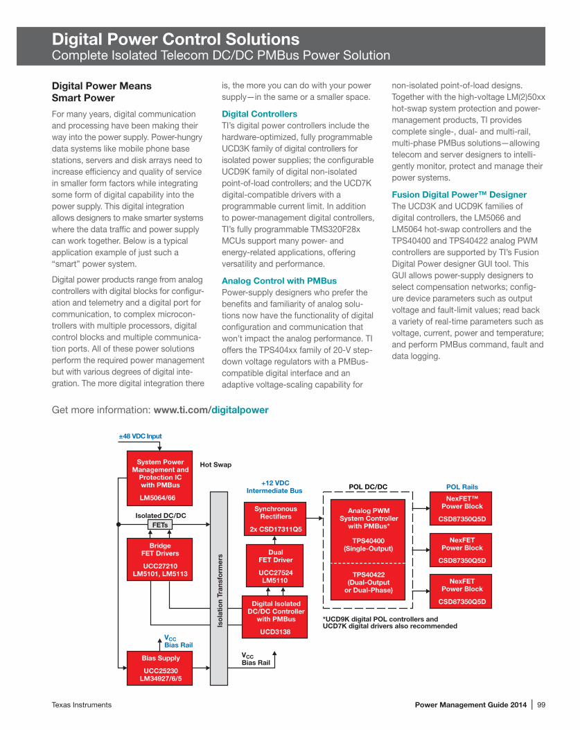
Texas Instruments Power Management Guide 2014 | 99
Digital Power Control SolutionsComplete Isolated Telecom DC/DC PMBus Power Solution
Digital Power Means Smart Power
For many years, digital communication and processing have been making their way into the power supply. Power-hungry data systems like mobile phone base stations, servers and disk arrays need to increase efficiency and quality of service in smaller form factors while integrating some form of digital capability into the power supply. This digital integration allows designers to make smarter systems where the data traffic and power supply can work together. Below is a typical application example of just such a “smart” power system.
Digital power products range from analog controllers with digital blocks for config ur-ation and telemetry and a digital port for communication, to complex microcon-trollers with multiple processors, digital control blocks and multiple communica-tion ports. All of these power solutions perform the required power management but with various degrees of digital inte -gration. The more digital integration there
is, the more you can do with your power supply—in the same or a smaller space.
Digital ControllersTI’s digital power controllers include the hardware-optimized, fully programmable UCD3K family of digital controllers for isolated power supplies; the configurable UCD9K family of digital non-isolated point-of-load controllers; and the UCD7K digital-compatible drivers with a pro gram mable current limit. In addition to power-management digital controllers, TI’s fully programmable TMS320F28x MCUs support many power- and energy-related applications, offering versatility and performance.
Analog Control with PMBusPower-supply designers who prefer the benefits and familiarity of analog solu-tions now have the functionality of digital configuration and communication that won’t impact the analog performance. TI offers the TPS404xx family of 20-V step-down voltage regulators with a PMBus- compatible digital interface and an adaptive voltage-scaling capability for
non-isolated point-of-load designs. Together with the high-voltage LM(2)50xx hot-swap system protection and power-management products, TI provides complete single-, dual- and multi-rail, multi-phase PMBus solutions—allowing telecom and server designers to intelli-gently monitor, protect and manage their power systems.
Fusion Digital Power™ DesignerThe UCD3K and UCD9K families of digital controllers, the LM5066 and LM5064 hot-swap controllers and the TPS40400 and TPS40422 analog PWM controllers are supported by TI’s Fusion Digital Power designer GUI tool. This GUI allows power-supply designers to select compensation networks; config-ure device parameters such as output voltage and fault-limit values; read back a variety of real-time parameters such as voltage, current, power and temperature; and perform PMBus command, fault and data logging.
System PowerManagement and
Protection ICwith PMBus
LM5064/66
+12 VDCIntermediate Bus POL Rails
Hot Swap
Isolated DC/DC
TPS40400(Single-Output)
POL DC/DC
±48 VDC Input
TPS40422(Dual-Output
or Dual-Phase)
Analog PWMSystem Controller
with PMBus*
Digital IsolatedDC/DC Controller
with PMBus
UCD3138
BridgeFET Drivers
UCC27210LM5101, LM5113
*UCD9K digital POL controllers and UCD7K digital drivers also recommended
DualFET Driver
UCC27524LM5110
Bias Supply
UCC25230LM34927/6/5
VCCBias Rail
VCCBias Rail
NexFET™Power Block
CSD87350Q5D
NexFETPower Block
CSD87350Q5D
NexFETPower Block
CSD87350Q5D
SynchronousRectifiers
2x CSD17311Q5
Iso
lati
on
Tran
sfo
rmer
s
FETs
Get more information: www.ti.com/digitalpower

100 | Power Management Guide 2014 Texas Instruments
Digital Power Control SolutionsIsolated and Non-Isolated Digital Power Controllers
TI focuses on non-isolated (UCD9K) and isolated (UCD3K) PWM digital power controllers, complementary Power Stage solutions (UCD7K), and PTD-series modules. These products are power- management specific and are well-suited for applications that benefit from configu-rability, communications, diagnostics and adaptive control solutions. They include both isolated and non-isolated solutions from AC line to point-of-load, covering uninterruptible power supplies (UPS), server, telecom and datacom applica-tions. The digital power ICs provide cost-effective solutions with greater levels of performance, reliability and flexibility than today’s pure analog designs. For the most up-to-date information on digital power technology and product availabil-ity, go to: www.ti.com/digitalpower
Key Benefits• High levels of integration:
Multiple outputs and phases with a single controllerIntegrated supply-voltage sequenc-ing, monitoring and marginingImproved reliability with fewer parts
• Advanced functionality:Real-time power monitoring, data logging and failure predictionFlexible control for varying operation modes and load characteristicsCalibration in manufacturing
• System optimization:Easily set fault limits, start character-istics after system is assembledEnhanced phase management
• Full programmability (UCD3K)
Digital Solution Features• PMBus Version 1.1• Power + Designer Graphical User
Interface tool• Programmable soft-start/stop
configuration• Voltage sequencing and tracking• Voltage margining and monitoring• Pre-biased, monotonic start-up
• Multiple levels of fault protection with selectable response
• Hardware-accelerated digital compensator
• Load sharing on multiphase power stages
• Frequency synchronization• Digital monitoring of power-supply
parameters
Up to 2
48-Pin
OutputsUp to 4 Phases
Up to 4 Outputs
64-PinUp to 6 Phases
Up to 4 OutputsUp to 8 Phases80-Pin
UCD92xx
UCD9248
UCD9246
UCD9224
Non-Isolated SMPS Integrated Driver and MOSFET
UCD7242
Isolated SMPS Drivers
Non-Isolated SMPS Drivers
UCD7xxxxUCD74111
UCD74120
UCD7231
UCD7201 UCD7100
Dual 6 A
Single 15 A
Dual 10 A
Single 25 A
20 A
6 A
Dual10 A PTD08D210W
15 A PTD08A015W
10 A
PTD Modules
PTD08A006W
PTD08A010W
PTD08A020W
Non-Isolated Digital Power-Train Modules
UCD9K Buck Controllers
Digital Power Stage Solutions
Up to 8 DPWM Outputs
64/80-PinUp to 4 Loops
Up to 8 DPWM Outputs
40/48-PinUp to 2 Loops
Up to 8 DPWM OutputsUp to 3 Loops40/64-Pin
UCD3xxx
UCD3138
UCD302x
UCD3040
UCD3K Isolated Power Controllers

Texas Instruments Power Management Guide 2014 | 101
Digital Power Control SolutionsIsolated and Non-Isolated Digital Power Controllers
Digital Point-of-Load ControllerUCD9248
Key Features• Controls up to 8 power stages and up to
4 voltage-feedback control loops• Output voltage is configurable from 0.4
to 4.0 V• Flexible configuration to control:
Four single or two dual power stages,Two 4-phase power stages, orOne 2-, 4-, 6- or 8-phase power stage
• Switching frequencies of up to 2 MHz• Supports conversion ratio of 12:1 at
2 MHz with 250-ps duty-cycle resolution• ±1-mV feedback resolution• Hardware-accelerated, digital 3-pole/
3-zero compensator• Can synchronize PWM clocks between
multiple UCD9248 devices
Diff Input 1
PWM1 Outputs
Diff Input 2PWM2 Outputs
Diff Input 3
PWM3 Outputs
Diff Input 4
PWM4 Outputs
Fusion Power Peripheral
Fusion Power Peripheral
Fusion Power Peripheral
Internal Data Bus
± 800-mVReference
0.5%,PMBus
33-MHzOscillator
LinearRegulator
Watchdog
2 Counters/Timers
33-MHz ARM7™ CPU Core
Data Flash w/ECC Up to 16 x 12-Bit, 200-kHz Channelsand 4 Comparators for Monitoring:Voltage Current Temperature
Fusion Power Peripheral
UCD9248
UCD9248 controller overview.
Graphical user interface (GUI) Digital Power developer tool simplifies the design process.
PMBus
1.2 V
3.3 V
1.8 V
1.5 V
1.8 V
1.2 V
3.3 V
12 DSPs
PLL1.8 V
RGMII1.5 V
Rapid I/O
1.2 V
Digital PowerUCD9248
Multiprocessor, multiple-supply-rail systems (three single-phase outputs and one dual-phase output) featuring UCD9248 and first- generation PTD modules.
Fusion Digital Power™ Designer
Get more information: www.ti.com/product/UCD9248

102 | Power Management Guide 2014 Texas Instruments
Digital Power Control SolutionsIsolated and Non-Isolated Digital Power Controllers
Isolated Digital Power-Control SolutionsUCD3138
The UCD3138 is a highly integrated and configurable digital-power-management controller that is optimized for AC/DC and isolated DC/DC power-supply applica-tions. The device offers an innovative path to increase power density and reliability in a broad range of power-supply topolo-gies used in servers, telecom rectifiers and high-power DC/DC modules. Digital control capabilities allow designers to do more with their power systems, includ-ing reuse of hardware designs across multiple platforms. Designers also have the versatility to fine-tune the perfor-mance and control parameters for each application, thus allowing faster time to market. The UCD3138 combines a powerful 32-bit microprocessor, high-speed precision data converters, multiple programmable hardware control loops and various communication engines in a small 6x6-mm package.
Key Features• Digital control—Three voltage or
current feedback loops with up to six high-resolution digital pulse-width-modulated (DPWM) outputs.
• Boosted peak- and light-load effi-ciency—Includes sync-FET soft on-off control, dynamic phase shedding, dynamic frequency adjustment and dynamic mode switching.
• Supports all isolated power-supply topologies—Controller support for single-phase, two-phase interleaved, or bridgeless power factor correction; hard-switching full bridge, phase-shifted full bridge, resonant LLC and other topologies.
• Integrates all essential protection features—Included functions are peak current-mode control, cycle-by-cycle peak-current limiting, high-speed input voltage feed-forward, overvolt-age, overcurrent and overtemperature protection.
Easy-to-Use GUI and Development ToolsDesigners will have easy access to several digital-power development tools such as full-voltage and feature-rich evaluation modules, development kits, reference designs, application firmware source code, programmerís manuals and the Code Composer Studio™ software development environment. TI’s Fusion Digital Power™ Designer graphical user interface (GUI) software tool provides flex-ible configuration of key power param-eters, as well as telemetry, logging and communication functions. A broad range of hardware design tools, such as control-card and open-loop evaluation modules, are available to select customers. In addi-tion, TI offers easy-to-use development kits and reference designs.
Evaluation Modules• UCD3138CC64EVM-030 control card• UCD3138OL64EVM-031—UCD3138
64-pin, open-loop board with socket
• UCD3138OL40EVM-032—UCD3138 40-pin, open-loop board with socket
• UCD3138064EVM-166—Control card in digitally controlled off-line isolated power converters
Development Kits• UCD3138PFCEVM-026—Universal-
input, 400-VOUT, AC/DC PFC devel-opment kit that is configurable into single- or two-phase interleaved and bridgeless topologies
• UCD3138PSFBEVM-027— 400-VIN/12-VOUT DC/DC phase-shifted full bridge
• UCD3138LLCEVM-028— 400-VIN/12-VOUT DC/DC half-bridge resonant LLC
• UCD3138HSFBEVM-029— 48-VIN/12-VOUT DC/DC hard-switching full bridge
Reference Designs • 48-VIN/12-VOUT 1/8-brick DC/DC refer-
ence design (hard-switching full bridge)
500-W AC/DC power supply reference design.
250-W 1/8th brick module reference design.
Get more information: www.ti.com/product/UCD3138

Texas Instruments Power Management Guide 2014 | 103
Digital Power Control SolutionsIsolated and Non-Isolated Digital Power Controllers
Selection Guide
Device Pin CountNumber
of OutputsNumber
of PhasesMaximum FSW
(MHz)PWM Resolution
(ps) CompensatorNonvolatile
Memory Price*
Digital Point-of-Load ControllersUCD9222/441 48/64 2/4 1 2 250 3-pole/3-zero 3-pole/3-zero 3.15/5.85
UCD9224 48 2 4 2 250 3-pole/3-zero 3-pole/3-zero 2.65
UCD9248/6 80/64 4 8/6 2 250 3-pole/3-zero Yes w/ECC 4.85/4.501UCD9222 and UCD9244 digital PWM controllers with support for TMS320C6670 and TMS320C6678 DSPs VID interface.*Suggested resale price in U.S. dollars in quantities of 1,000.
DeviceNumber of
Outputs Output ConfigurationOutput Type1
Peak IOUT Source/Sink
(A)
Rise/Fall Time (ns)
VCC Range
(V)
Propagation Delay (ns)
Input Threshold
Dead-Time Control
Protection Features Price*
Digital Power MOSFET DriversUCD7231 2 Non-inverting CMOS 6/6 10/10 4.5 to 15.5 25 CMOS/TTL Adaptive Adjustable 0.60
UCD7232 2 Non-inverting CMOS 6/6 10/10 4.5 to 15.5 25 CMOS/TTL Adaptive Adjustable 0.60
UCD7100 1 Uncommitted/Non-inverting TrueDrive™ 4/4 10/10 4.5 to 16 20 CMOS/TTL Adaptive Adjustable 0.99
UCD7201 2 Uncommitted/Non-inverting TrueDrive 4/4 10/10 4.5 to 16 20 CMOS/TTL Adaptive Adjustable 1.201Output type: TrueDrive is the hybrid bipolar/CMOS output architecture for improved current drive capability at low voltages (at Miller threshold).*Suggested resale price in U.S. dollars in quantities of 1,000.
Device Pin CountNumber of DPWM
Outputs
Number of Independent
Control LoopsDPWM Resolution
(ps)DPWM Maximum Frequency (MHz)
Program Flash Memory Size (KB)
Number of 12-Bit ADC Channels Compensator Price*
Digital Isolated Power ControllersUCD3020 48 6 2 250 2 32 9 3-pole/3-zero 2.45
UCD3028 40 8 2 250 2 32 9 3-pole/3-zero 2.35
UCD3040 64/80 8 4 250 2 32 11/15 3-pole/3-zero 3.75/4.05
UCD3138 40/64 8 3 250 2 32 7/14 2-pole/2-zero 2.70/4.10
UCD3138064 64 8 3 250 2 64 9 2-pole/2-zero 4.89
DeviceInput Voltage
(V)Output
Configuration Current Rating (A) Price*
Digital Power StagesUCD7242 4.5 to 18 Dual 10/10 2.65
UCD74106 4.5 to 14 Single 6 1.00
UCD74111 4.5 to 14 Single 15 2.95
UCD74120 4.5 to 14 Single 25 3.95
DeviceInput Voltage
(V)Output
Configuration Current Rating (A) Price*
Digital Power-Train ModulesPTD08A006W 4.75 to 14 Single 6 6.90
PTD08A010W 4.75 to 14 Single 10 8.50
PTD08A015W 4.75 to 14 Single 15 9.80
PTD08A020W 4.75 to 14 Single 20 12.90
PTD08D210W 4.75 to 14 Dual 10/10 9.25
PTD08A210W 4.75 to 14 Single 10 7.50*Suggested resale price in U.S. dollars in quantities of 1,000. New devices are listed in bold red.

104 | Power Management Guide 2014 Texas Instruments
Supervisors and Reset ICs
Window Comparator for Over- and Under-Voltage DetectionTPS3700
Features• Wide supply range: 1.8 to 18 V• High accuracy threshold: 1% (over
temperature range)• Open drain OV and UV output• Available in TSOT23-6 package
Get more information: www.ti.com/product/TPS3700
Supervisory Circuits, Reset ICs and Sequencers Family of Products
Watchdog
TPS3420TPS3421TPS3422
Push Button
TPS3123/4
TPS3820/8
TPS3823
Backup-Battery Switch
TL77xxA/B
TL7700
LM809/10TPS3831/9
LMS33460
TPS3809
UCCx946
TPS3813 bq2205TPS3606TPS3619
TPS3617
Chip-Enable Gate
TPS3600
TPS3610TPS3613
TPS3124
TPS3824
Reset Active High Watchdog Power Fail
TPS3125
TPS3825
TPS3837
TPS3126TPS3103/6
TPS3828
Dual
TPS3705
LM3710
Power Fail
TPS3305-xx
Manual Reset
TPS3807TPS3806
TPS3700 TL7770-xxTPS3805
TPS3707
LM3704
LMC6953
TPS3106 TPS3306-xx
Watchdog,Power Fail
Triple
TPS3510
TPS3514
TPS386596
TPS386040
TPS3513
TPS3511
TLC77xx
LP3470
TL7757/9
TPS3307-xx
Manual Reset,Active High Reset
Quad
TPS386000
Single
Watchdog
Reset Active High
Manual Reset
LM3724
TPS3801
TPS3808
TPS3836
TPS3838
TPS389x
TPS3803TLV8xx
Power Fail
Reset Active High
TPS3110
New devices shown in bold red.
LM8364/5UCx543/4
TPS3422
Push Button
VITP
OU
TB
INB–
VITPR1
GND
1.8 to 18 V
OUTA
OUTB
R2
R3
Vmonitor
INA+
INB
VDD RP1
1
2
3
6
5
4
OUTB
VDD
INB–
OUTA
GND
INA+
DDC PACKAGEThinSOT23-6(TOP VIEW)
TPS3700
OU
TA
INA+
For more information, please visit: www.ti.com/supervisors

Texas Instruments Power Management Guide 2014 | 105
Supervisors and Reset ICs
Selection Guide
Device Num
ber o
f Sup
ervis
ors
SupervisedVoltages Package(s)
VDDRange
(V)
IDD(typ) (µA)
TimeDelay(ms) W
atch
dog T
imer
W
DI (s
ec)
Rese
t Thr
esho
ld Ac
cura
cy (%
)
Manu
al Re
set/E
nable
Res
et
Activ
e-Lo
w Re
set/O
utpu
t
Activ
e-Hi
gh R
eset
/Out
put
Rese
t Out
put T
opolo
gy1
Powe
r-Fail
PFI/
PFO
Over
volta
ge D
etec
tion
Over
curre
nt D
etec
tion
Chip-
Enab
led G
ating
Comments Price*
General Purpose Supply SupervisorsLM3724 1 2.32, 3.08, 4.63 SOT23-5, D, W 1 to 6 6 0.02 ±2.5 4 4 OD 4 0.95/0.80
LP3470 1 2.63, 2.75, 2.83, 2.93, 3.08, 3.65, 4.0, 4.38, 4.63, 4.8 SOT23-5 0.5 to 5 16 0.3 ±1 4 OD 0.595/0.562
LM3704 2 2.32, 3.08, 3.6 micro SMD-9, MSOP-10 1 to 5.5 28 0.02 ±2 4 4 CMOS, OD 4 0.77
LM3710 2 2.32, 3.08, 4.63 MINI SOIC 1 to 5.5 28 0.02 0.0062 to 25.6 ±2 4 4 CMOS, OD 4 1.10
LM8364 1 2.0 SOT23-5 1 to 6 0.65 0.3 ±2.5 4 CMOS, OD 0.24LM8365 1 2.75, 4.5 SOT23-5 1 to 6 0.65 0.1 ±2.5 4 CMOS, OD 0.25LM809 1 2.63, 2.93, 3.08, 4.38, 4.63 SOT23-3, LLP-6, D, W 1 to 6 15 0.02 ±1.5 4 CMOS 0.23LM810 1 4.63 SOT23-3, D, W 1 to 6 15 0.02 ±1.5 4 CMOS 0.23LMS33460 1 3 SC-70 1 to 7 1 0.2 ±5 4 OD 0.17LMC6953 2 3.3, 3.5 SOIC-8 1.5 to 6 800 0.0005 ±3 4 4 OD 1.44TPS3895 1 Adj. SON-6 1.7 to 6.5 6 0.04, Prog — 0.25 4 4 PP Ultra small 0.60TPS3896 1 Adj. SON-6 1.7 to 6.5 6 0.04, Prog — 0.25 4 4 PP Ultra small 0.60TPS3897 1 Adj. SON-6 1.7 to 6.5 6 0.04, Prog — 0.25 4 4 OD Ultra small 0.60TPS3898 1 Adj. SON-6 1.7 to 6.5 6 0.04, Prog — 0.25 4 4 OD Ultra small 0.60TLV803 1 2.5/3/3.3/5 3SOT-23 1.1 to 6 9 200 — 2.00 4 OD 0.20TLV810 1 2.5/3/3.3/5 3SOT-23 1.1 to 6 9 200 — 2.00 4 PP 0.20
TPS3808 1 Adj./0.9/1.2/1.5/1.8/2.5/ 3.0/3.3/5.0/EEPROM SOT-23, SON-6 1.8 to 6.5 2.4 Prog — 0.5 4 4 OD 0.70
TPS3103 1 1.2/1.5/2.0/3.3 SOT-23 0.4 to 3.3 1.2 130 — 0.75 4 4 OD 4 0.90TPS3123 1 1.2/1.5/1.8 SOT-23 0.75 to 3.3 14 180 1.4 3.6 4 4 PP 0.85TPS3124 1 1.2/1.5/1.8 SOT-23 0.75 to 3.3 14 180 1.4 3.6 4 4 PP 0.85TPS3125 1 1.2/1.5/1.8/3.0 SOT-23 0.75 to 3.3 14 180 — 3.6 4 4 4 PP 0.80TPS3126 1 1.2/1.5/1.8 SOT-23 0.75 to 3.3 14 180 — 3.5 4 4 4 OD 0.80TPS3128 1 1.2/1.5/1.8 SOT-23 0.75 to 3.3 14 180 1.4 3.5 4 4 OD 0.85TPS3800 1 2.7 SC-70 1.6 to 6.0 9 100 — 2 4 4 PP 0.40TPS3801 1 Adj./1.8/2.5/3.0/3.3/5.0 SC-70 1.6 to 6.0 9 200 — 2 4 4 PP 0.40TPS3802 1 3.0/3.3 SC-70 1.6 to 6.0 9 400 — 2 4 4 PP 0.40
TPS3803 1 Adj./1.5 SC-70 1.3 to 6.0 3 — — 1.5 4 OD Voltage detector 0.25
TLV809 1 2.5/3.0/3.3/5.0 SOT-23 2.0 to 6.0 9 200 — 2.2 4 PP 0.25
TPS3813 1 2.5/3.0/3.3/5.0 SOT-23 2.0 to 6.0 9 25 Window 2.2 4 OD Window watchdog 0.90
TPS3820/8-xx 1 3.3/5.0 SOT-23 1.1 to 5.5 15 25/200 0.2/1.6 2.4 4 4 PP/OD 0.65TPS3823 1 2.5/3.0/3.3/5.0 SOT-23 1.1 to 5.5 15 200 1.6 2.4 4 4 PP 0.65TPS3824-xx 1 2.5/3.0/3.3/5.0 SOT-23 1.1 to 5.5 15 200 1.6 2.2 4 4 PP 0.65TPS3825-xx 1 3.3/5.0 SOT-23 1.1 to 5.5 15 200 — 2.2 4 4 4 PP 0.55TPS3831 1 — SON-4 0.6 to 6.5 0.15 200 — 1.5 4 4 PP Ultra small 0.30TPS3839 1 — SON-4, SOT-23 0.6 to 6.5 0.15 200 — 1.5 4 PP Ultra small 0.21TPS3836/8 1 1.8/2.5/3.0/3.3 SOT-23 1.6 to 6.0 0.22 10/200 — 2.5 4 4 PP/OD 0.85TPS3837 1 1.8/2.5/3.0/3.3 SOT-23 1.6 to 6.0 0.22 10/200 — 2.4 4 4 PP 0.85TLC77xx 1 Adj./2.5/3.3/3.0/5.0 SO-8, DIP-8, TSSOP-8 2.0 to 6.0 9 Prog — 5.5 4 4 PP 0.65TPS3807 2 3/3.5 SC-70 1.8 to 6.5 3.5 20 — 1 4 OD 0.95TPS3106 2 Adj./0.9/1.6/3.3 SOT-23 0.4 to 3.3 1.2 130 — 0.75 4 4 OD 0.90TPS3110 2 Adj./0.9/1.2/1.5/3.3 SOT-23 0.4 to 3.3 1.2 130 1.1 0.75 4 4 PP 0.99TPS3305-xx 2 1.8/2.5/3.3/5.0 SO-8, MSOP-8 2.7 to 6.0 15 200 1.6 2.7 4 4 4 PP 1.00TPS3306-xx 2 1.5/1.8/2.0/2.5/3.3/5.0 SO-8, MSOP-8 2.7 to 6.0 15 100 0.8 2.7 4 OD 4 1.05
TPS3700 2 Adj. ThinSOT23-6, SON-6 1.8 to 18 5.5 — — 0.25 4 4 OD Window comparator 0.70
TPS3705-xx 2 3.0/3.3/5.0 SO-8, MSOP-8 2.0 to 6.0 30 200 1.6 2.1 4 4 PP 4 0.80TPS3707-xx 2 2.5/3.0/3.3/5.0 SO-8, MSOP-8 2.0 to 6.0 20 200 — 2.2 4 4 4 PP 4 0.75
1PP = push-pull, OD = open drain, OC = open collector. *Suggested resale price in U.S. dollars in quantities of 1,000.
Note: Custom voltages can be provided. Minimum order New devices are listed in bold red.quantities may apply. Contact TI for details and availability.

106 | Power Management Guide 2014 Texas Instruments
Supervisors and Reset ICs
Selection Guide (Continued)
Device Num
ber o
f Sup
ervis
ors
SupervisedVoltages Package(s)
VDDRange
(V)
IDD(typ) (µA)
TimeDelay(ms) W
atch
dog T
imer
W
DI (s
ec)
Rese
t Thr
esho
ld Ac
cura
cy (%
)
Manu
al Re
set/E
nable
Res
et
Activ
e-Lo
w Re
set/O
utpu
t
Activ
e-Hi
gh R
eset
/Out
put
Rese
t Out
put T
opolo
gy1
Powe
r-Fail
PFI/
PFO
Over
volta
ge D
etec
tion
Over
curre
nt D
etec
tion
Chip-
Enab
led G
ating
Comments Price*
General Purpose Supply Supervisors (Continued)
TPS3805 2 Adj./3.3 SC-70 1.3 to 6.0 3 — — 1.5 4 PP Voltage detector 0.34
TPS3806 2 Adj./2.0/3.3 SOT-23 1.3 to 6.0 3 — — 2 4 OD Voltage detector 0.45
TPS3307-xx 3 Adj./1.8/2.5/3.3/5.0 SO-8, MSOP-8 2.0 to 6.0 15 200 — 2.7 4 4 4 PP 1.05TPS386596 4 Adj./3.0 MSOP-8 1.8 to 6.5 7.5 Prog — 0.25 4 4 OD 4 1.25TPS3860x0 4 Adj. (includes negative rail) QFN 1.8 to 6.5 9 Prog 0.6 0.25 4 4 4 PP/OD 4 1.95
Battery Backup Switchover Supply SupervisorsTPS3600 1 2.0/2.5/3.3/5.0 TSSOP-14 1.6 to 5.5 20 100 0.8 2.3 4 4 PP 4 4 2.15TPS3606-33 1 3.3 MSOP-10 1.6 to 5.5 20 100 0.8 2 4 4 PP 4 1.45TPS3610 1 1.8/5.0 TSSOP-14 1.6 to 5.5 20 100 0.8 2 4 PP 4 4 1.80TPS3613-01 1 Adjustable MSOP-10 1.6 to 5.5 20 100 — 1.7 4 4 4 PP 4 1.50TPS3619 1 3.3/5.0 MSOP-8 1.6 to 5.5 15 100 — 2 4 4 PP 4 1.10
Special Function Supply Supervisors
TPS3510/1 3 3.3/5.0/12.0 SO-8, DIP-8 4 to 15 1 mA 300 — 9.1 4 OD 4 4PC power supplies 0.45
TPS3513/4 3 3.3/5.0/12.0 SO-14, DIP-14 4.5 to 15 1 mA 300 — 9.1 4 OD 4 4 4PC power supplies 0.70
1PP = push-pull, OD = open drain, OC = open collector. *Suggested resale price in U.S. dollars in quantities of 1,000.
Note: Custom voltages can be provided. Minimum order New devices are listed in bold red.quantities may apply. Contact TI for details and availability.
Sequencers
Selection Guide
DeviceNumber of
SupervisorsSupervised
Voltages
Number of Sequenced
Outputs Package(s)
VDDRange
(V)
IDD(typ) (µA)
TimeDelay(ms) Comments Price*
LM3880 — — 3 SOT23-6 2.7 to 5.5 25 Fixed 0.50LM3881 — — 3 MSOP-8 2.7 to 5.5 80 Prog 0.50UCD9090 10 Prog. by software GUI — QFN-64 3.3 to 12 50 mA Prog 3.60UCD90120A 13 Prog. by software GUI — QFN-64 3.3 to 12 50 mA Prog 4.95UCD90124A 13 Prog. by software GUI — QFN-64 3.3 to 12 50 mA Prog With fan control 6.45UCD90160 16 Prog. by software GUI — QFN-64 3.3 to 12 50 mA Prog 5.65UCD90910 10 Prog. by software GUI — QFN-64 3.3 to 12 50 mA Prog With fan control 5.90
*Suggested resale price in U.S. dollars in quantities of 1,000.

Texas Instruments Power Management Guide 2014 | 107
Push-Button Controllers
Current Power Monitors
Selection Guide
Device Description
Common-Mode Range
Gain (V/V)
Output Type
Input Offset (+/-)(max)
(µV)
CMRR (min) (dB)
Quiescent Current
(+/-)(typ)(mA)
VS
Package(s) Price* (min)
(V)(max)
(V)(min)
(V)(max)
(V)
INA226 High-side measurement, bi-directional current power monitor with I2C interface 0 36 1 I2C 10 126 0.33 2.7 5.5 MSOP-10 1.30
INA210 Voltage output, high/low-side measurement, bi-directional zero-drift series current power monitor –0.3 26 200 Voltage 35 105 0.065 2.7 26 µQFN-10,
SC70-6 0.65
INA219 Zero-drift, bi-directional current power monitor 0 26 Programmable I2C 50 100 0.7 3 5.5 SOIC-8, SOT-23-8 0.80
INA230 Precision digital/current/voltage/power monitor 0 28 1 I2C 50 100 330 2.7 5.5 QFN-16 1.15
INA282 Wide common mode range, bidirectional, high accuracy current power monitor –14 80 50 Voltage 70 120 0.6 2.7 18 SOIC-8 1.25
LMP8640 Precision high-voltage current sense amplifier –2 76 20, 50, 100 Voltage 900 60 0.72 2.7 12 SOT-6 0.89
LMP8645 Precision high-voltage current sense amplifier –2 76 Programmable Voltage 1000 60 0.61 2.7 12 SOT-6 0.89
LMP8646 Precision current limiter –2 76 Programmable Voltage 1000 95 0.38 2.7 12 SOT-6 1.20*Suggested resale price in U.S. dollars in quantities of 1,000.
Single and Dual Push-Button ControllersTPS3420, TPS3421, TPS3422
TPS342x family of devices provide the ability to perform a hardware system reset during a software crash. It also eliminates the need to remove batteries to activate a reset. These controllers are used in designs with an embedded battery to ensure a hard- and full-system reset when needed. They include a fail-safe option when the system/microprocessor freezes and a system reset is required. Holding one or two external button switches for x amount of seconds generates a reset. To improve system stability, short-period switch closures are rejected by the setup delay time (t_setup), as shown in the timing diagram.
Key Features• Very small, 1.45x1-mm SON package• Low supply current: 250 nA• User-selectable input delay using
two-state logic• Fixed-pulse or input-dependent reset
behavior
Applications• Smart phones• Tablets• Ultrabooks• Notebooks• Routers• Consumer medicalReset
SwitchInput
t_setup = 4 s1.5 s
No reset pulsewhen t < t_setup
Reset pulsewhen t = t_setup
Get more information: www.ti.com/product/TPS3420D, TPS3421EC or TPS3422EG

108 | Power Management Guide 2014 Texas Instruments
DDR Power Solutions
TI DDR Power Application
Selection Guide
DeviceVIN (V)
IOUT (A) Provides DDR Type
Plug-in ModulesPTH03010/50/60W 2.95 to 3.65 6/10/15 VTT 1, 2, 3
PTH05010/50/60W 4.5 to 5.5 6/10/15 VTT 1, 2, 3
PTH12010/50/60L 10.8 to 13.2 6/10/12 VTT 1, 2, 3
ControllersTPS40042 2.25 to 5.5 Up to 15 VTT 1, 2, 3
TPS40057 8 to 40 Up to 20 VTT 1, 2, 3
Controller + LDO
TPS51116, TPS51216/716/916 3 to 281 Up to 25 A for VDDQ, 3 (2-A VTT for TPS51216/916) VTT, VDDQ, VREF 1, 2, 3, LV3, LP3
Dual ControllerTPS51020 4.5 to 28 Up to 15 VTT, VDDQ, VREF 1, 2
Termination Voltage (Source and Sink) LDOsTPS51100 1.2 to 3.62 Up to 3 VTT, VREF 1, 2, 3, LV3, LP3
TPS51200 1.1 to 3.53 Up to 3 VTT, VREF 1, 2, 3, LV3, LP3
TPS51206 VTT+0.4 V to 3.5 V Up to 2 VTT, VREF 1, 2, 3, LV3, LP4
LP2995 2.2 to 5.5 1.5 VTT, VREF 1
LP2996 1.8 to 5.5 1.5 VTT, VREF 1, 2
LP2996A 1.5 to 5.5 1.5 VTT, VREF 1, 2, 3
LP2997 1.8 to 5.5 0.5 VTT, VREF 1, 2
LP2998 1.35 to 5.5 1.5 VTT, VREF 1, 2, 3
Switchers with Integrated FETsTPS54372 3 to 6 3 VTT 1, 2, 3
TPS53317, TPS54672 3 to 6 6 VTT 1, 2, 3 , LV3, LP3
TPS54972 3 to 4 9 VTT 1, 2, 3
TPS51362/7 3 to 221 10/12 VDDQ 1, 2, 3, LV3, LP3
TPS560200 4.5 to 17 0.5 VPP 41Needs 4.5- to 5.5-V bias.2Needs 4.75- to 5.25-V bias.3Needs 2.4- to 3.5-V bias.
TI Voltage Controller (TPS51116)
SODIMM 2SODIMM 1
Data/Strobes
2 Clock Pairs
VREF VDD (SPD)
VDD (VDD, VDDQ, VDDL)
VSS (VDD, VSSQ, VSSL, VSS(SPD))
VTT
Rt
VTT
4.5 to 28 V (DC)
Rt
Data/Strobes
2 Clock Pairs
Address/Commandand Control Lines
Address/Commandand Control Lines
VDDQ
VSSQ
SW1
R1
R2
VDDQ
VSSQ
SW1
R1
R2
ODT Circuit ODT Circuit
DDR2Memory
Controller
(SSTL_18 I/O) Battery(Adapter)
Register/PLL
Register/PLL

Texas Instruments Power Management Guide 2014 | 109
ResourcesDesign Support
PowerLab™ Power Reference Design Library
WEBENCH Design Center online design and prototyping tools put an award-winning online design environment right at your fingertips. Design, optimize, generate your prototype and download your test vectors—all online. And you can do it all for free, anywhere, anytime.
Select It—Choose from only those parts that meet your specifications• Input your design requirements• Choose a recommended part from a
customized list
Design It—Create your custom BOM using readily available parts• Tune your design quickly with the opti-
mization tool to balance design objec-tives for efficiency and footprint
• Adjust components and use charts to make design decisions on a wide selection of electrical characteristics
• Exchange parts and use bill-of- materials graphs for easy external component selection based on effi-ciency, footprint, cost or vendors Get more information
www.ti.com/webench
Features• Extensive collection of tested power-
management reference designs• Hundreds of power-management
designs for a wide range of applica tions and power-conversion topologies
• Reference designs include both isolated and non-isolated designs for lighting, telecommunication, comput-ing, consumer electronics and more
Get more information:www.ti.com/powerlab
The PowerLab library includes an inter-active and powerful search engine for design engineers looking for a proven and tested solution to their power-supply requirements. This interactive search tool allows engineers to find designs by application, topology, input type, input voltage or output voltage.
WEBENCH® Design Center Saves Development Time and Cost
Analyze It—Solve your design problems before you prototype• Simulate your circuit and evaluate
performance using electrical and thermal simulations
• Simulate electrical characteristics, choose probe points and examine waveforms to determine performance
• Simulate thermal behavior and your circuit on a PCB in your defined envi-ronment and view color heat maps
• Overlay alternate circuits and compare results to get optimal performance
Build It—Save weeks getting your final design into production• Request samples and purchase parts
or demo boards• Receive your custom prototyping kit
the next business day• Download your automatically gener-
ated CAD files, assembly details, test instructions and complete perform-ance results

110 | Power Management Guide 2014 Texas Instruments
ResourcesPackaging
Surface Mount Packages
Package TypePackage
Designator Key Characteristics
Small Outline Packages
Small Outline Integrated Circuit (SOIC)
D, DW, DWU, DTH, DTC, DDA, DVB, DWP
High MSL rating* (MSL1/MSL2), variable size availability
Mini Small Outline Package (MSOP) DGK, DGS Small form factor, thin
package
Heat Sink Small Outline Package (HSOP)
DWP, DWD Thermally enhanced SOP (low to mid power)
Small Shrink Outline Package (SSOP)
DL, DB, DF, DBQ, DCE, DCT
High MSL rating* (MSL1/MSL2), higher stand-off height
Thin Shrink Small Outline Package (TSSOP)
DA, PW, DBT
Variable pin count options available, high MSL rating* (MSL1/MSL2), small form factor
Exposed Pad Thin Shrink Small Outline Package (HTSSOP)
PWP, DAP, DAD, DCA
Thermally enhanced TSSOP (low to high power); various pin count options available
Power Small Outline Package (PSOP3)
DKP (slug down), DKD (slug up)
Very high power handling capability, mechanically robust package
Quad Leaded Packages
Thin Quad Flat Pack (TQFP)
PFB, PAG, PJT, PBS, PAG
High pin count, leadframe based package
Exposed Pad Thin Quad Flat Pack (HTQFP)
PAP, PJD, PZP, PHP, PNP, PHD
Thermally enhanced TQFP (mid to high power)
Small Outline Transistors
Small Outline Transistor (SC-70) DCK Mini form factor
Small Outline Transistor Package (SOT23)
DBV, DCN, DDC, thin SOT
Small form factor, high MSL rating* (MSL1/MSL2)
Small Outline Transistor (SOT223)
DCY, DCQ High MSL rating* (MSL1/MSL2)
Transistor Outline (TO236) DBZ Small form factor
Leaded Packages
Plastic Flange Mount Package (DDPak/TO-263)
KTT, KTW Very high power handling capability
Leadless Packages
Small Outline No Leads (SON)
DRB, DRC, DRD, DRK, DRM, DRN, DRT, DSE, DSG, DSJ
Small footprint, thermal package (low to mid power)
Package TypePackage
Designator Key Characteristics
Leadless Packages (Continued)
Quad Flatpack No Leads (QFN)
RGC, RGE, RGF, RGP, RGT, RGW, RGY, RGZ, RHA, RHB, RHD, RHF, RHH, RHL, RSA, RSB, RSH, RSJ, RSL, RSM, RTE, RTH, RTQ, RTT, RUK, RUV, RVA
Compact footprint, thermal package (mid to high power), available in variable thicknesses
Flip-Chip Power Packages RSJ High power handling
capability
Ball Grid Arrays (BGAs)Wafer Chip Scale Package (WCSP)/ Die Sized Ball Grid Array (DSBGA)
YEG, YEK, YEJ, YEA, YZA, YED
Die size package, very small form factor, finer pitch
MicroStar BGA™ ZGU
Controllable count density, variable thickness option availability
MicroStar Junior™ BGA ZQE, ZQZ
Smaller sized MicroStar BGA, controllable pin count density
PicoStar™ YFMExtremely small sized package, ultra-thin, board embeddable
BGA ZVD Very high pin count density
Through-Hole Packages
Package TypePackage
Designator Key Characteristics
Plastic Dual Inline Package (PDIP) P, N, NT, NTD
Recommended for wave soldering, excellent board-level reliability
Transistor Outline (TO220) KC
Very high power handling capability, recommended for wave soldering, mechanically robust
Package Modules
Package TypePackage
Designator Key Characteristics
Power Modules — Integrated passives, enhanced functionality
*MSL rating should be checked for individual device.
Surface Mount Packages (Continued)
Get more information:www.ti.com/packaging

Texas Instruments Power Management Guide 2014 | 111
ResourcesPackaging
The PowerPAD package should be connected to the appropriate internal signal plane as specified in the product datasheet. Depending on the electrical properties of the thermally conductive epoxy used to connect the Integrated Circuit (IC) to the lead frame, the PowerPAD may have a low impedance connection to the internal signal plane as specified in the product datasheet.
You can find additional information in the following resources. Technical literature can be accessed online with www.ti.com/lit/litnumber by replacing
Connecting the PowerPAD™ litnumber with one of the following literature numbers shown in parentheses.• Remember to check the CAD format
for your package under “Symbols/Footprints,” available in all TI Product Folders
• Download the “PowerPAD Made Easy” application brief (SLMA004) in conjunction with the “PowerPAD Thermally Enhanced Package” techni-cal brief (SLMA002)
Internal CopperNot Tied to Vias
PowerPAD™-to-PWBSolder Connection
Bottom LayerCopper Tied to Vias
Internal CopperTied to Vias
IC Body
Thermal Vias
Top Layer Copper
• Specific information on QFN/SON packages is available in application reports (SLUA271 and SCBA017)
• Visit TI’s Analog & Mixed-Signal KnowledgeBase at: support.ti.com/sc/knowledgebase
• Ask our experts your specific design questions via email by selecting Analog & Mixed-Signal email support in the Contact Tech Support frame at: support.ti.com
Connect with your Power-Management peers andcustomers to ask questions,share knowledge, exploreideas, and solve problems.
Join the discussion today!
TI E2E™Communityengineer.to.engineer,solving problemswww.ti.com/e2epower

112 | Power Management Guide 2014 Texas Instruments
ResourcesDevice Index
Device Page Device Page Device Page Device Page Device Page Device Pagebq2000/T . . . . . . . . . . . . . . 58bq2002/C/E/F . . . . . . . . . . . 58bq2004/E/H . . . . . . . . . . . . 58bq2005 . . . . . . . . . . . . . . . 58bq2019 . . . . . . . . . . . . . . . 60bq2023 . . . . . . . . . . . . . . . 60bq2031 . . . . . . . . . . . . . . . 58bq20z655-R1 . . . . . . . . . . . 60bq24030/31/35 . . . . . . . . . 57bq24032A/38 . . . . . . . . . . . 57bq24040/41 . . . . . . . . . . . . 57bq24045 . . . . . . . . . . . . . . 57bq24050/52 . . . . . . . . . . . . 57bq24055 . . . . . . . . . . . . . . 57bq24072/72T . . . . . . . . . . . 57bq24073 . . . . . . . . . . . . . . 57bq24074 . . . . . . . . . . . . . . 57bq24075T/79T . . . . . . . . . . 57bq24090/91 . . . . . . . . . . . . 57bq24092/93 . . . . . . . . . . . . 57bq24095 . . . . . . . . . . . . . . 57bq24130 . . . . . . . . . . . . . . 57bq24133 . . . . . . . . . . . . . . 57bq24140 . . . . . . . . . . . . . . 57bq24153A/58 . . . . . . . . . . . 57bq24156A/59 . . . . . . . . . . . 57bq24157 . . . . . . . . . . . . . . 57bq24160/A . . . . . . . . . . . . . 57bq24161/B . . . . . . . . . . . . . 57bq24163 . . . . . . . . . . . . . . 57bq24165 . . . . . . . . . . . . . . 57bq24166 . . . . . . . . . . . . . . 57bq24167 . . . . . . . . . . . . . . 57bq24168 . . . . . . . . . . . . . . 57bq24170 . . . . . . . . . . . . . . 58bq24171 . . . . . . . . . . . . . . 58bq24172 . . . . . . . . . . . . . . 58bq24180 . . . . . . . . . . . . . . 57bq24185 . . . . . . . . . . . . . . 57bq24187 . . . . . . . . . . . . . . 57bq24190 . . . . . . . . . . . . . . 57bq24192 . . . . . . . . . . . . . . 57bq24192I . . . . . . . . . . . . . . 57bq24193 . . . . . . . . . . . . . . 57bq24195 . . . . . . . . . . . . . . 57bq24195L . . . . . . . . . . . . . 57bq24196 . . . . . . . . . . . . . . 57bq24210 . . . . . . . . . . . . . . 58bq24232 . . . . . . . . . . . . . . 57bq24232H . . . . . . . . . . . . . 57bq24250/51 . . . . . . . . . . . . 57bq24253 . . . . . . . . . . . . . . 57bq24257 . . . . . . . . . . . . . . 57bq24260 . . . . . . . . . . . . . . 57bq24261 . . . . . . . . . . . . . . 57bq24262 . . . . . . . . . . . . . . 57bq24270/71 . . . . . . . . . . . . 57bq24272 . . . . . . . . . . . . . . 57bq24273 . . . . . . . . . . . . . . 57bq24278 . . . . . . . . . . . . . . 57bq24300/4/5 . . . . . . . . . . . 59bq24308 . . . . . . . . . . . . . . 59bq24312 . . . . . . . . . . . . . . 59bq24313 . . . . . . . . . . . . . . 59bq24314/A . . . . . . . . . . . . . 59bq24314C . . . . . . . . . . . . . 59bq24315 . . . . . . . . . . . . . . 59bq24316 . . . . . . . . . . . . . . 59bq24350 . . . . . . . . . . . . . . 59bq24351 . . . . . . . . . . . . . . 59bq24352 . . . . . . . . . . . . . . 59bq24380 . . . . . . . . . . . . . . 59bq24381 . . . . . . . . . . . . . . 59bq24382 . . . . . . . . . . . . . . 59bq24400/1 . . . . . . . . . . . . . 58bq24450 . . . . . . . . . . . . . . 58bq24600 . . . . . . . . . . . . . . 58bq24610 . . . . . . . . . . . . . . 58bq24616 . . . . . . . . . . . . . . 58bq24617 . . . . . . . . . . . . . . 58bq24618 . . . . . . . . . . . . . . 58
bq24620 . . . . . . . . . . . . . . 58bq24630 . . . . . . . . . . . . . . 58bq24640 . . . . . . . . . . . . . . 58bq24650 . . . . . . . . . . . . . . 58bq24707A . . . . . . . . . . . . . 58bq24715 . . . . . . . . . . . . . . 58bq24725A . . . . . . . . . . . . . 58bq24735 . . . . . . . . . . . . . . 58bq24765 . . . . . . . . . . . . . . 58bq25040 . . . . . . . . . . . . . . 57bq25050 . . . . . . . . . . . . . . 57bq25060 . . . . . . . . . . . . . . 57bq25070 . . . . . . . . . . . . . . 58bq25504 . . . . . . . . . . . . . . 58bq25505 . . . . . . . . . . . . . . 58bq25570 . . . . . . . . . . . . . . 58bq26200 . . . . . . . . . . . . . . 60bq26220 . . . . . . . . . . . . . . 60bq27421 . . . . . . . . . . . . . . 60bq27425 . . . . . . . . . . . . . . 60bq27510 . . . . . . . . . . . . . . 60bq27520 . . . . . . . . . . . . . . 60bq2753x . . . . . . . . . . . . . . 60bq27541 . . . . . . . . . . . . . . 60bq28400 . . . . . . . . . . . . . . 60bq28550 . . . . . . . . . . . . . . 60bq28z560 . . . . . . . . . . . . . 60bq2920x . . . . . . . . . . . . . . 61bq2944x . . . . . . . . . . . . . . 61bq2945xy . . . . . . . . . . . . . . 61bq2946xy . . . . . . . . . . . . . . 61bq3050 . . . . . . . . . . . . . . . 60bq3055 . . . . . . . . . . . . . . . 60bq3060 . . . . . . . . . . . . . . . 60bq33100 . . . . . . . . . . . . . . 60bq34z100 . . . . . . . . . . . . . 60bq34z110 . . . . . . . . . . . . . 60bq34z651 . . . . . . . . . . . . . 60bq34z950 . . . . . . . . . . . . . 60bq500210 . . . . . . . . . . 59, 61bq500211 . . . . . . . . . . 59, 61bq500212A . . . . . . . . . 59, 61bq500412A . . . . . . . . . 59, 61bq500414Q . . . . . . . . . 59, 61bq51003 . . . . . . . . . . . 59, 61bq51010B . . . . . . . . . . 59, 61bq51013B . . . . . . . . . . 59, 61bq51020 . . . . . . . . . . . 59, 61bq51021 . . . . . . . . . . . 59, 61bq51221 . . . . . . . . . . . 59, 61bq76925 . . . . . . . . . . . . . . 61bq76PL536A . . . . . . . . 60, 61bq76PL536A-Q1 . . . . . . . . 61bq7716xy . . . . . . . . . . . . . . 61bq7718xy . . . . . . . . . . . . . . 61bq77908A . . . . . . . . . . . . . 61bq77910A . . . . . . . . . . . . . 61bq77PL157A4225 . . . . . . . 61bq77PL900 . . . . . . . . . . . . 61BUF01900 . . . . . . . . . . . . . 68BUF01901 . . . . . . . . . . . . . 68BUF04701 . . . . . . . . . . . . . 68BUF05703 . . . . . . . . . . . . . 68BUF05704 . . . . . . . . . . . . . 68BUF06703 . . . . . . . . . . . . . 68BUF06704 . . . . . . . . . . . . . 68BUF07702/3/4 . . . . . . . . . . 68BUF08630 . . . . . . . . . . . . . 68BUF08800 . . . . . . . . . . . . . 68BUF08821 . . . . . . . . . . . . . 68BUF08832 . . . . . . . . . . . . . 68BUF11702/4/5 . . . . . . . . . . 68BUF12800 . . . . . . . . . . . . . 68BUF12840 . . . . . . . . . . . . . 68BUF16820 . . . . . . . . . . . . . 68BUF16821 . . . . . . . . . . . . . 68BUF18830 . . . . . . . . . . . . . 68BUF20800 . . . . . . . . . . . . . 68BUF20820 . . . . . . . . . . . . . 68BUF22821 . . . . . . . . . . . . . 68CSD13201W10 . . . . . . . . . 47
CSD13303W1015 . . . . . . . 47CSD13381F4 . . . . . . . . . . . 47CSD15571Q2 . . . . . . . . . . . 47CSD16301Q2 . . . . . . . . . . . 47CSD16321Q5 . . . . . . . . . . . 47CSD16321Q5C . . . . . . . . . . 49CSD16322Q5 . . . . . . . . . . . 47CSD16322Q5C . . . . . . . . . . 49CSD16323Q3 . . . . . . . . . . . 47CSD16323Q3C . . . . . . . . . . 47CSD16325Q5 . . . . . . . . . . . 47CSD16325Q5C . . . . . . . . . . 49CSD16327Q3 . . . . . . . . . . . 47CSD16340Q3 . . . . . . . . . . . 47CSD16342Q5A . . . . . . . . . . 47CSD16401Q5 . . . . . . . . . . . 47CSD16403Q5A . . . . . . . . . . 47CSD16404Q5A . . . . . . . . . . 48CSD16406Q3 . . . . . . . . . . . 47CSD16407Q5 . . . . . . . . . . . 48CSD16407Q5C . . . . . . . . . . 49CSD16408Q5 . . . . . . . . . . . 48CSD16408Q5C . . . . . . . . . . 49CSD16409Q3 . . . . . . . . . . . 47CSD16410Q5A . . . . . . . . . . 48CSD16411Q3 . . . . . . . . . . . 47CSD16412Q5A . . . . . . . . . . 48CSD16413Q5A . . . . . . . . . . 48CSD16414Q5 . . . . . . . . . . . 48CSD16415Q5 . . . . . . . . . . . 48CSD16556Q5B . . . . . . . . . . 48CSD17301Q5A . . . . . . . . . . 48CSD17302Q5A . . . . . . . . . . 48CSD17303Q5 . . . . . . . . . . . 48CSD17304Q3 . . . . . . . . . . . 47CSD17305Q5A . . . . . . . . . . 48CSD17306Q5A . . . . . . . . . . 48CSD17307Q5A . . . . . . . . . . 48CSD17308Q3 . . . . . . . . . . . 47CSD17309Q3 . . . . . . . . . . . 47CSD17310Q5A . . . . . . . . . . 48CSD17311Q5 . . . . . . . . 48, 99CSD17312Q5 . . . . . . . . . . . 48CSD17313Q2 . . . . . . . . . . . 47CSD17313Q2Q1 . . . . . . . . . 47CSD17322Q5A . . . . . . . . . . 48CSD17327Q5A . . . . . . . . . . 48CSD17381F4 . . . . . . . . . . . 47CSD17483F4 . . . . . . . . . . . 47CSD17501Q5A . . . . . . . . . . 48CSD17505Q5A . . . . . . . . . . 48CSD17506Q5A . . . . . . . . . . 48CSD17507Q5A . . . . . . . 48, 93CSD17510Q5A . . . . . . . . . . 48CSD17522Q5A . . . . . . . . . . 48CSD17527Q5A . . . . . . . . . . 48CSD17551Q3A . . . . . . . . . . 47CSD17551Q5A . . . . . . . . . . 48CSD17552Q3A . . . . . . . . . . 47CSD17552Q5A . . . . . . . . . . 48CSD17553Q5A . . . . . . . . . . 48CSD17555Q5A . . . . . . . . . . 48CSD17556Q5B . . . . . . . . . . 48CSD17559Q5 . . . . . . . . . . . 48CSD18501Q5A . . . . . . . . . . 48CSD18502KCS . . . . . . . . . . 49CSD18502Q5B . . . . . . . . . . 48CSD18503KCS . . . . . . . . . . 49CSD18503Q5A . . . . . . . . . . 48CSD18504KCS . . . . . . . . . . 49CSD18504Q5A . . . . . . . . . . 48CSD18531Q5A . . . . . . . . . . 48CSD18532KCS . . . . . . . . . . 49CSD18532NQ5B . . . . . . . . . 48CSD18532Q5B . . . . . . . . . . 48CSD18533KCS . . . . . . . . . . 49CSD18533Q5A . . . . . . . . . . 48CSD18534KCS . . . . . . . . . . 49CSD18534Q5A . . . . . . . . . . 48CSD18537NKCS . . . . . . . . . 49CSD18537NQ5A . . . . . . . . . 48
CSD18563Q5A . . . . . . . . . . 48CSD19501KCS . . . . . . . . . . 49CSD19502Q5B . . . . . . . . . . 48CSD19503KCS . . . . . . . . . . 49CSD19505KCS . . . . . . . . . . 49CSD19506KCS . . . . . . . . . . 49CSD19531KCS . . . . . . . . . . 49CSD19531Q5A . . . . . . . . . . 48CSD19532Q5B . . . . . . . . . . 49CSD19533KCS . . . . . . . . . . 49CSD19533Q5A . . . . . . . . . . 49CSD19535KCS . . . . . . . . . . 49CSD19536KCS . . . . . . . . . . 49CSD22202W15 . . . . . . . . . 50CSD23201W10 . . . . . . . . . 49CSD23381F4 . . . . . . . . . . . 49CSD25201W15 . . . . . . . . . 50CSD25211W1015 . . . . . . . 49CSD25213W10 . . . . . . . . . 49CSD25301W1015 . . . . . . . 49CSD25303W1015 . . . . . . . 49CSD25310Q2 . . . . . . . . . . . 50CSD25402Q3A . . . . . . . . . . 50CSD25481F4 . . . . . . . . . . . 49CSD25483F4 . . . . . . . . . . . 49CSD75204W15 . . . . . . . . . 50CSD75205W1015 . . . . . . . 50CSD75207W15 . . . . . . . . . 50CSD75211W1723 . . . . . . . 50CSD75301W1015 . . . . . . . 50CSD86311W1723 . . . . . . . 47CSD86330Q3D . . . . . . . . . . 51CSD86350Q5D . . . . . . . . . . 51CSD86360Q5D . . . . . . . . . . 51CSD87312Q3E . . . . . . . . . . 47CSD87330Q3D . . . . . . . . . . 51CSD87331Q3D . . . . . . . . . . 51CSD87333Q3D . . . . . . . . . . 51CSD87350Q5D . . . . . . . 51, 99CSD87351Q5D . . . . . . . . . . 51CSD87351ZQ5D . . . . . . . . . 51CSD87352Q5D . . . . . . . . . . 51CSD87353Q5D . . . . . . . . . . 51CSD87381P . . . . . . . . . . . . 51CSD87384M . . . . . . . . . . . 51CSD87588N . . . . . . . . . . . . 51CSD88537ND . . . . . . . . . . . 47CSD88539ND . . . . . . . . . . . 47CSD95372AQ5M . . . . . . . . 51CSD95372BQ5M . . . . . . . . 51CSD95373AQ5M . . . . . . . . 51CSD95375Q4M . . . . . . . . . 51CSD96370Q5M . . . . . . . . . 51CSD96371Q5M . . . . . . . . . 51CSD97370AQ5M . . . . . . . . 51CSD97370Q5M . . . . . . . . . 51CSD97374Q4M . . . . . . . . . 51CSD97376Q4M . . . . . . . . . 51INA210 . . . . . . . . . . . . . . 107INA219 . . . . . . . . . . . . . . 107INA226 . . . . . . . . . . . . . . 107INA230 . . . . . . . . . . . . . . 107INA282 . . . . . . . . . . . . . . 107LM(2)5005 . . . . . . . . . . . . . 28LM(2)5007 . . . . . . . . . . . . . 28LM(2)5010/A . . . . . . . . . . . 28LM(2)5017 . . . . . . . . . . . . . 28LM(2)5018 . . . . . . . . . . . . . 27LM(2)5019 . . . . . . . . . . . . . 27LM(2)5037 . . . . . . . . . . . . . . 8LM(2)5085/A . . . . . . . . . . . 39LM(2)5088 . . . . . . . . . . . . . 39LM(2)5115/A . . . . . . . . . 9, 39LM(2)5116 . . . . . . . . . . . . . 39LM(2)5117 . . . . . . . . . . . . . 39LM(2)5118 . . . . . . . . . . . . . 40LM(2)5119 . . . . . . . . . . . . . 40LM10502 . . . . . . . . . . . . . . 82LM10503 . . . . . . . . . . . . . . 84LM10504/6 . . . . . . . . . . . . 84LM10524 . . . . . . . . . . . . . . 84
LM1084 . . . . . . . . . . . . . . . 54LM20123/33/43 . . . . . . . . . 27LM20124/34/44/54 . . . . . . 27LM20125/45 . . . . . . . . . . . 27LM20136/46 . . . . . . . . . . . 27LM20242 . . . . . . . . . . . . . . 28LM20323/33/43 . . . . . . . . . 28LM21212-1 . . . . . . . . . . . . 27LM21212-2 . . . . . . . . . . . . 27LM21215 . . . . . . . . . . . . . . 27LM21215A . . . . . . . . . . . . . 27LM21305 . . . . . . . . . . . . . . 27LM22670/73/76 . . . . . . . . . 23LM22671/74 . . . . . . . . . . . 23LM22672/75 . . . . . . . . . . . 23LM22677/78/79 . . . . . . . . . 23LM22680 . . . . . . . . . . . 23, 25LM25011/A . . . . . . . . . . . . 28LM25056/A . . . . . . . . . . . . 89LM25061 . . . . . . . . . . . . . . 88LM25066/A . . . . . . . . . 87, 89LM25066I/A . . . . . . . . . 87, 89LM25069 . . . . . . . . . . . . . . 88LM25101A/B/C . . . . . . . . . 13LM25119 . . . . . . . . . . . . . . 81LM25574 . . . . . . . . . . . 23, 25LM25575 . . . . . . . . . . . 23, 25LM25576 . . . . . . . . . . . 23, 25LM2585 . . . . . . . . . . . . . . . 34LM2586 . . . . . . . . . . . . . . . 34LM2587 . . . . . . . . . . . . . . . 34LM2588 . . . . . . . . . . . . . . . 34LM26001 . . . . . . . . . . . . . . 28LM26003 . . . . . . . . . . . . . . 28LM2621 . . . . . . . . . . . . . . . 33LM2622 . . . . . . . . . . . . . . . 33LM2623 . . . . . . . . . . . . . . . 33LM26400Y . . . . . . . . . . . . . 84LM2642 . . . . . . . . . . . . . . . 40LM26420 . . . . . . . . . . . 81, 84LM2647 . . . . . . . . . . . . . . . 40LM26480 . . . . . . . . . . . 81, 84LM26484 . . . . . . . . . . . . . . 84LM2657 . . . . . . . . . . . . . . . 40LM2698 . . . . . . . . . . . . . . . 33LM2700 . . . . . . . . . . . . . . . 33LM2717 . . . . . . . . . . . . . . . 27LM2717-ADJ . . . . . . . . . . . 27LM2731 . . . . . . . . . . . . . . . 33LM27313 . . . . . . . . . . . . . . 33LM2733 . . . . . . . . . . . . . . . 33LM2735 . . . . . . . . . . . . . . . 33LM27402 . . . . . . . . . . . . . . 39LM27403 . . . . . . . . . . . 37, 39LM2742 . . . . . . . . . . . . . . . 39LM2743 . . . . . . . . . . . . . . . 39LM2744 . . . . . . . . . . . . . . . 39LM2745 . . . . . . . . . . . . . . . 39LM2747 . . . . . . . . . . . . . . . 39LM2748 . . . . . . . . . . . . . . . 39LM2756 . . . . . . . . . . . . . . . 72LM2771 . . . . . . . . . . . . . . . 41LM2772 . . . . . . . . . . . . . . . 41LM2773 . . . . . . . . . . . . . . . 41LM2852 . . . . . . . . . . . . . . . 23LM2853 . . . . . . . . . . . . . . . 23LM2854 . . . . . . . . . . . . . . . 23LM2936HV . . . . . . . . . . . . . 54LM3000 . . . . . . . . . . . . . . . 40LM3100 . . . . . . . . . . . . . . . 23LM3102 . . . . . . . . . . . . . . . 23LM3103 . . . . . . . . . . . . . . . 23LM3150 . . . . . . . . . . . . . . . 36LM3151 . . . . . . . . . . . . . . . 36LM3152 . . . . . . . . . . . . . . . 36LM3153 . . . . . . . . . . . . . . . 36LM3209-G3 . . . . . . . . . . . . 44LM3212 . . . . . . . . . . . . . . . 44LM3224 . . . . . . . . . . . . . . . 33LM3241 . . . . . . . . . . . . . . . 44LM3242 . . . . . . . . . . . . . . . 44
LM3243 . . . . . . . . . . . . . . . 44LM3248 . . . . . . . . . . . . . . . 44LM3262 . . . . . . . . . . . . . . . 44LM3263 . . . . . . . . . . . . . . . 44LM3269 . . . . . . . . . . . . . . . 44LM3279 . . . . . . . . . . . . . . . 44LM3280 . . . . . . . . . . . . . . . 84LM3290/91 . . . . . . . . . . . . 44LM3310 . . . . . . . . . . . . . . . 33LM3311 . . . . . . . . . . . . . . . 33LM3402/02HV . . . . . . . . . . 65LM3404/04HV . . . . . . . . . . 65LM3406/06HV . . . . . . . . . . 65LM3409/09HV . . . . . . . . . . 65LM3410X/Y . . . . . . . . . . . . 65LM3414/14HV . . . . . . . . . . 65LM3421/23/29 . . . . . . . . . . 65LM3424 . . . . . . . . . . . . . . . 65LM3430 . . . . . . . . . . . . . . . 40LM3431 . . . . . . . . . . . . . . . 65LM3433/34 . . . . . . . . . . . . 65LM3444 . . . . . . . . . . . . . . . 64LM3445 . . . . . . . . . . . . . . . 64LM3447 . . . . . . . . . . . . . . . 64LM3448 . . . . . . . . . . . . . . . 64LM3450/50A . . . . . . . . . . . 64LM3463 . . . . . . . . . . . . . . . 65LM3464/64A . . . . . . . . . . . 65LM3466 . . . . . . . . . . . . . . . 65LM3475 . . . . . . . . . . . . . . . 39LM3477 . . . . . . . . . . . . . . . 39LM3478 . . . . . . . . . . . . . . . 40LM3481 . . . . . . . . . . . . . . . 40LM3485 . . . . . . . . . . . . . . . 39LM3488 . . . . . . . . . . . . . . . 40LM3489 . . . . . . . . . . . . . . . 39LM34902/4 . . . . . . . . . . . . 91LM34910/C . . . . . . . . . . . . 28LM34917A . . . . . . . . . . . . . 28LM34919/B/C . . . . . . . . . . 28LM3492/92HC . . . . . . . . . . 65LM34927/6/5 . . . . . . . . . 9, 99LM3525M-H . . . . . . . . . . . . 95LM3525M-L . . . . . . . . . . . . 95LM3526M-H . . . . . . . . . . . . 96LM3526M-L . . . . . . . . . . . . 96LM3528 . . . . . . . . . . . . . . . 71LM3530 . . . . . . . . . . . . . . . 71LM3532 . . . . . . . . . . . . . . . 71LM3533 . . . . . . . . . . . . . . . 71LM3535 . . . . . . . . . . . . . . . 71LM3537 . . . . . . . . . . . . . . . 71LM3538 . . . . . . . . . . . . . . . 71LM3544M-H . . . . . . . . . . . . 96LM3544M-L . . . . . . . . . . . . 96LM3550 . . . . . . . . . . . . . . . 73LM3554 . . . . . . . . . . . . . . . 73LM3555 . . . . . . . . . . . . . . . 73LM3556 . . . . . . . . . . . . . . . 73LM3559 . . . . . . . . . . . . . . . 73LM3560 . . . . . . . . . . . . . . . 73LM3561 . . . . . . . . . . . . . . . 73LM3565 . . . . . . . . . . . . . . . 73LM3630 . . . . . . . . . . . . . . . 71LM3642 . . . . . . . . . . . . . . . 73LM3646 . . . . . . . . . . . . . . . 73LM3668 . . . . . . . . . . . . . . . 35LM3670 . . . . . . . . . . . . . . . 29LM3671 . . . . . . . . . . . . . . . 29LM3678 . . . . . . . . . . . . . . . 30LM3686 . . . . . . . . . . . . . . . 84LM3687 . . . . . . . . . . . . . . . 84LM3691 . . . . . . . . . . . . . . . 30LM3697 . . . . . . . . . . . . . . . 71LM3704 . . . . . . . . . . . . . . 105LM3710 . . . . . . . . . . . . . . 105LM3724 . . . . . . . . . . . . . . 105LM3743 . . . . . . . . . . . . . . . 39LM3753 . . . . . . . . . . . . 39, 40LM3753/54 . . . . . . . . . . . . 39LM3754 . . . . . . . . . . . . . . . 40

Texas Instruments Power Management Guide 2014 | 113
ResourcesDevice Index
LM3880 . . . . . . . . . . . . . . 106LM3881 . . . . . . . . . . . . . . 106LM4510 . . . . . . . . . . . . . . . 33LM5000 . . . . . . . . . . . . . . . 33LM5001 . . . . . . . . . . . . . . . 33LM5002 . . . . . . . . . . . . . . . 32LM5006 . . . . . . . . . . . . . . . 28LM5008/A . . . . . . . . . . . . . 28LM5009/A . . . . . . . . . . . . . 27LM5015 . . . . . . . . . . . . . . . . 8LM5017 . . . . . . . . . . . . . 9, 26LM5020 . . . . . . . . . . . . . 8, 40LM5021 . . . . . . . . . . . . . . . . 8LM5022 . . . . . . . . . . . . . 8, 40LM5022/C . . . . . . . . . . . . . 40LM5023 . . . . . . . . . . . . . . . . 8LM5025/A/B/C . . . . . . . . . . . 9LM5026 . . . . . . . . . . . . . . . . 9LM5027/A . . . . . . . . . . . . . . 9LM5030 . . . . . . . . . . . . . . . . 9LM5032 . . . . . . . . . . . . . . . . 8LM5033 . . . . . . . . . . . . . . . . 9LM5034 . . . . . . . . . . . . . . . . 8LM5035/A/B/C . . . . . . . . . . . 8LM5039 . . . . . . . . . . . . . . . . 8LM5041/A/B . . . . . . . . . . . . 9LM5045 . . . . . . . . . . . . . . . . 8LM5046 . . . . . . . . . . . . . . . . 9LM5050-1 . . . . . . . . . . . . . 89LM5050-2 . . . . . . . . . . . . . 89LM5051 . . . . . . . . . . . . . . . 89LM5056 . . . . . . . . . . . . . . . 89LM5060/Q . . . . . . . . . . . . . 88LM5064 . . . . . . . . . . . . 89, 99LM5066 . . . . . . . . . . . . 89, 99LM5067 . . . . . . . . . . . . . . . 88LM5068 . . . . . . . . . . . . . . . 88LM5069 . . . . . . . . . . . . . . . 88LM5070 . . . . . . . . . . . . . . . 93LM5071 . . . . . . . . . . . . . . . 93LM5072 . . . . . . . . . . . . . . . 93LM5073 . . . . . . . . . . . . . . . 93LM5100A/B/C . . . . . . . . . . 13LM5101A/B/C . . . . . . . . . . 13LM5110 . . . . . . . . . . . . 12, 99LM5111 . . . . . . . . . . . . . . . 12LM5112 . . . . . . . . . . . . . . . 12LM5113 . . . . . . . . . . . . 13, 99LM5114A/B . . . . . . . . . . . . 12LM5119 . . . . . . . . . . . . . . . 81LM5121/2 . . . . . . . . . . 38, 40LM5122 . . . . . . . . . . . . . . . 38LM5134 . . . . . . . . . . . . . . . 12LM5574 . . . . . . . . . . . . . . . 23LM5575 . . . . . . . . . . . . . . . 23LM5576 . . . . . . . . . . . . . . . 23LM5642 . . . . . . . . . . . . . . . 40LM5642x . . . . . . . . . . . . . . 40LM809 . . . . . . . . . . . . . . . 105LM810 . . . . . . . . . . . . . . . 105LM8207 . . . . . . . . . . . . . . . 68LM8364 . . . . . . . . . . . . . . 105LM8365 . . . . . . . . . . . . . . 105LM8502 . . . . . . . . . . . . . . . 72LM8801 . . . . . . . . . . . . . . . 30LM9076 . . . . . . . . . . . . . . . 54LMC6953 . . . . . . . . . . . . . 105LMH2100 . . . . . . . . . . . . . . 45LMH2110 . . . . . . . . . . . . . . 45LMH2120 . . . . . . . . . . . . . . 45LMH2121 . . . . . . . . . . . . . . 45LMP8640 . . . . . . . . . . . . . 107LMP8645 . . . . . . . . . . . . . 107LMP8646 . . . . . . . . . . . . . 107LMR10510 . . . . . . . . . . . . . 24LMR10515 . . . . . . . . . . . . . 24LMR10520 . . . . . . . . . . . . . 24LMR12007 . . . . . . . . . . . . . 24LMR12010 . . . . . . . . . . . . . 24LMR14006 . . . . . . . . . . . . . 24,LMR14203 . . . . . . . . . . . . . 24,
LMR14206 . . . . . . . . . . . . . 24,LMR22007 . . . . . . . . . . . . . 24LMR24210 . . . . . . . . . . . . . 24LMR24220 . . . . . . . . . . . . . 24,LMR62014 . . . . . . . . . . . . . 34LMR62421 . . . . . . . . . . . . . 34LMR64010 . . . . . . . . . . . . . 34LMR70503 . . . . . . . . . . . . . 34LMS33460 . . . . . . . . . . . . 105LMV221 . . . . . . . . . . . . . . . 45LMV225 . . . . . . . . . . . . . . . 45LMV226 . . . . . . . . . . . . . . . 45LMV228 . . . . . . . . . . . . . . . 45LMV232 . . . . . . . . . . . . . . . 45LMV242 . . . . . . . . . . . . . . . 45LMZ10500/01 . . . . . . . 16, 24LMZ10503/04/05 . . . . . . . . 17LMZ10503/04/05EXT . . . . . 17LMZ12001/02/03 . . . . . . . . 17LMZ12001/02/03EXT . . . . . 17LMZ12008/10 . . . . . . . . . . 17LMZ13608/10 . . . . . . . . . . 17LMZ14201/02/03 . . . . . . . . 17LMZ14201/02/03EXT . . . . . 17LMZ14201H/02H/03H . . . . 17LMZ22003/5 . . . . . . . . . . . 17LMZ22008/10 . . . . . . . . . . 17LMZ23603/5 . . . . . . . . . . . 17LMZ23608/10 . . . . . . . . . . 17LMZ30602 . . . . . . . . . . . . . 15LMZ30604 . . . . . . . . . . . . . 15LMZ30606 . . . . . . . . . . . . . 15LMZ31503 . . . . . . . . . . . . . 15LMZ31506 . . . . . . . . . . . . . 15LMZ31520 . . . . . . . . . . . . . 15LMZ31530 . . . . . . . . . . . . . 15LMZ31704 . . . . . . . . . . . . . 15LMZ31707 . . . . . . . . . . . . . 15LMZ31710 . . . . . . . . . . . . . 15LMZ34002 . . . . . . . . . . . . . 15LMZ35003 . . . . . . . . . . . . . 15LP2966 . . . . . . . . . . . . . . . 55LP2967 . . . . . . . . . . . . . . . 55LP2989/LV . . . . . . . . . . . . . 54LP2995 . . . . . . . . . . . . . . 108LP2996 . . . . . . . . . . . . . . 108LP2996A . . . . . . . . . . . . . 108LP2997 . . . . . . . . . . . . . . 108LP2998 . . . . . . . . . . . . . . 108LP3470 . . . . . . . . . . . . . . 105LP3851(1/2/3) . . . . . . . . . . 54LP3851x . . . . . . . . . . . . . . 54LP38798-ADJ . . . . . . . 53, 54LP388(1/2/3) . . . . . . . . . . . 54LP3885(2/5/8) . . . . . . . . . . 54LP3885(3/6/9) . . . . . . . . . . 54LP38851 . . . . . . . . . . . . . . 54LP3905 . . . . . . . . . . . . . . . 84LP3906 . . . . . . . . . . . . . . . 84LP3907 . . . . . . . . . . . . 81, 84LP3910 . . . . . . . . . . . . 82, 84LP3913 . . . . . . . . . . . . . . . 82LP3918 . . . . . . . . . . . . . . . 82LP3921 . . . . . . . . . . . . . . . 82LP3923 . . . . . . . . . . . . . . . 82LP3925 . . . . . . . . . . . . 82, 83LP3927 . . . . . . . . . . . . . . . 82LP3971/2 . . . . . . . . . . . . . . 84LP3974 . . . . . . . . . . . . .83-85LP3996 . . . . . . . . . . . . . . . 55LP5521 . . . . . . . . . . . . . . . 72LP5522 . . . . . . . . . . . . . . . 72LP5523 . . . . . . . . . . . . . . . 72LP5524 . . . . . . . . . . . . . . . 72LP590(0/7) . . . . . . . . . . . . . 54LP5907 . . . . . . . . . . . . .53-55LP5996 . . . . . . . . . . . . . . . 55LP8340 . . . . . . . . . . . . . . . 54LP8543 . . . . . . . . . . . . . . . 71LP8545 . . . . . . . . . . . . . . . 71LP8550 . . . . . . . . . . . . . . . 71
LP8553 . . . . . . . . . . . . . . . 71LP8556 . . . . . . . . . . . . . . . 71LP8557 . . . . . . . . . . . . 70, 71LP8720 . . . . . . . . . . . . . . . 84LP8725 . . . . . . . . . . . . . . . 84LP8728 . . . . . . . . . . . . . . . 81LP8755 . . . . . . . . . . . . . . . 85LP8900 . . . . . . . . . . . . . . . 55MC34063A . . . . . . . . . 33, 34PMP5592 . . . . . . . . . . . . . . 93PMP8752 . . . . . . . . . . . . . . 93PTD08A006W . . . . . 100, 103PTD08A010W . . . . . 100, 103PTD08A015W . . . . . 100, 103PTD08A020W . . . . . 100, 103PTD08A210W . . . . . . . . . 103PTD08D210W . . . . . 100, 103PTH03000W . . . . . . . . . . . . 19PTH03010/50/60W . . . . . 108PTH03010W . . . . . . . . . . . . 19PTH03010Y . . . . . . . . . . . . 19PTH03020W . . . . . . . . . . . . 19PTH03030W . . . . . . . . . . . . 19PTH03050W . . . . . . . . . . . . 19PTH03050Y . . . . . . . . . . . . 19PTH03060W . . . . . . . . . . . . 19PTH03060Y . . . . . . . . . . . . 19PTH04000W . . . . . . . . . . . . 19PTH04040W . . . . . . . . . . . . 19PTH04070W . . . . . . . . . . . . 19PTH04T220/221W . . . . 18, 19PTH04T230/231W . . . . . . . 19PTH04T240/241W . . . . . . . 19PTH04T260/261W . . . . . . . 19PTH05000W . . . . . . . . . . . . 19PTH05010/50/60W . . . . . 108PTH05010W . . . . . . . . . . . . 19PTH05010Y . . . . . . . . . . . . 19PTH05020W . . . . . . . . . . . . 19PTH05030W . . . . . . . . . . . . 19PTH05050W . . . . . . . . . . . . 19PTH05050Y . . . . . . . . . . . . 19PTH05060W . . . . . . . . . . . . 19PTH05060Y . . . . . . . . . . . . 19PTH05T210W . . . . . . . . . . . 19PTH08000W . . . . . . . . . . . . 19PTH08080W . . . . . . . . . . . . 19PTH08T210W . . . . . . . . . . . 19PTH08T220/221W . . . . . . . 19PTH08T230/231W . . . . . . . 19PTH08T240/241W . . . . . . . 19PTH08T240F . . . . . . . . . . . 19PTH08T250/255W . . . . . . . 19PTH08T260/261W . . . . . . . 19PTH12000L/W . . . . . . . . . . 19PTH12010/50/60L . . . . . . 108PTH12010L/W . . . . . . . . . . 19PTH12010Y . . . . . . . . . . . . 19PTH12020L/W . . . . . . . . . . 19PTH12030L/W . . . . . . . . . . 19PTH12040W . . . . . . . . . . . . 19PTH12050L/W . . . . . . . . . . 19PTH12050Y . . . . . . . . . . . . 19PTH12060L/W . . . . . . . . . . 19PTH12060Y . . . . . . . . . . . . 19PTN04050A . . . . . . . . . . . . 20PTN04050C . . . . . . . . . . . . 19PTN78000A . . . . . . . . . . . . 20PTN78000W/H . . . . . . . . . . 19PTN78020A . . . . . . . . . . . . 20PTN78020W/H . . . . . . . . . . 19PTN78060A . . . . . . . . . . . . 20PTN78060W/H . . . . . . . . . . 19PTR08060W . . . . . . . . . . . . 19PTR08100W . . . . . . . . . . . . 19PTV03010W . . . . . . . . . . . . 19PTV03020W . . . . . . . . . . . . 19PTV05010W . . . . . . . . . . . . 19PTV05020W . . . . . . . . . . . . 19PTV08T250W . . . . . . . . . . . 19PTV12010L/W . . . . . . . . . . 19
PTV12020L/W . . . . . . . . . . 19REG710 . . . . . . . . . . . . . . . 42REG71050 . . . . . . . . . . 42, 71REG711 . . . . . . . . . . . . . . . 42TCA6507 . . . . . . . . . . . . . . 71TL3842B/3B/4B/5B . . . . . . . 8TL4242 . . . . . . . . . . . . . . . 77TL494 . . . . . . . . . . . . . . . . . 8TL497A . . . . . . . . . . . . .32-34TL499A . . . . . . . . . . . . 33, 34TL594 . . . . . . . . . . . . . . . . . 8TL598 . . . . . . . . . . . . . . . . . 8TL7660 . . . . . . . . . . . . . . . 41TLC59025 . . . . . . . . . . . . . 77TLC59108 . . . . . . . . . . . . . 77TLC59108F . . . . . . . . . . . . 77TLC59116 . . . . . . . . . . . . . 77TLC59116F . . . . . . . . . . . . 77TLC5916 . . . . . . . . . . . . . . 77TLC5917 . . . . . . . . . . . . . . 77TLC59208F . . . . . . . . . . . . 77TLC5921 . . . . . . . . . . . . . . 77TLC59210 . . . . . . . . . . . . . 77TLC59211 . . . . . . . . . . . . . 77TLC59212 . . . . . . . . . . . . . 77TLC59213/A . . . . . . . . . . . . 77TLC5922 . . . . . . . . . . . . . . 77TLC5923 . . . . . . . . . . . . . . 77TLC5924 . . . . . . . . . . . . . . 77TLC5925 . . . . . . . . . . . . . . 77TLC5926 . . . . . . . . . . . . . . 77TLC5927 . . . . . . . . . . . . . . 77TLC5928 . . . . . . . . . . . . . . 77TLC59281 . . . . . . . . . . . . . 77TLC59283 . . . . . . . . . . 76, 77TLC59284 . . . . . . . . . . . . . 77TLC5929 . . . . . . . . . . . . . . 77TLC5940 . . . . . . . . . . . . . . 77TLC59401 . . . . . . . . . . . . . 77TLC5941 . . . . . . . . . . . . . . 77TLC5942 . . . . . . . . . . . . . . 77TLC5943 . . . . . . . . . . . . . . 77TLC5944 . . . . . . . . . . . . . . 77TLC5945 . . . . . . . . . . . . . . 77TLC5946 . . . . . . . . . . . . . . 77TLC59461 . . . . . . . . . . . . . 77TLC5947 . . . . . . . . . . . . . . 77TLC59482 . . . . . . . . . . . . . 77TLC5948A . . . . . . . . . . . . . 77TLC5949 . . . . . . . . . . . . . . 77TLC5951 . . . . . . . . . . . . . . 77TLC5952 . . . . . . . . . . . . . . 77TLC5960 . . . . . . . . . . . . . . 72TLC5970 . . . . . . . . . . . . . . 77TLC5971 . . . . . . . . . . . . . . 77TLC59711 . . . . . . . . . . 75, 77TLC5973 . . . . . . . . . . . 75, 77TLC59731 . . . . . . . . . . . . . 77TLC77xx . . . . . . . . . . . . . . 105TLV431A . . . . . . . . . . . . . . 93TLV62080 . . . . . . . . . . . . . 29TLV62084 . . . . . . . . . . . . . 29TLV62090 . . . . . . . . . . . . . 29TLV62130 . . . . . . . . . . . . . 29TLV62150 . . . . . . . . . . . . . 29TLV62565 . . . . . . . . . . . . . 29TLV705xx . . . . . . . . . . . . . . 55TLV707xx . . . . . . . . . . . . . . 55TLV710 . . . . . . . . . . . . . . . 55TLV711 . . . . . . . . . . . . . . . 55TLV713xx . . . . . . . . . . . . . . 55TLV716 . . . . . . . . . . . . . . . 55TLV717xx . . . . . . . . . . . . . . 55TLV803 . . . . . . . . . . . . . . 105TLV809 . . . . . . . . . . . . . . 105TLV810 . . . . . . . . . . . . . . 105TPS2000 . . . . . . . . . . . . . . 95TPS2001 . . . . . . . . . . . . . . 95TPS2002 . . . . . . . . . . . . . . 95TPS2003 . . . . . . . . . . . . . . 95TPS2020 . . . . . . . . . . . . . . 95
TPS2020-Q1 . . . . . . . . . . . 95TPS2021 . . . . . . . . . . . . . . 95TPS2021-Q1 . . . . . . . . . . . 95TPS2021 . . . . . . . . . . . . . . 95TPS2022 . . . . . . . . . . . . . . 95TPS2022-Q1 . . . . . . . . . . . 95TPS2023 . . . . . . . . . . . . . . 95TPS2024 . . . . . . . . . . . . . . 95TPS2024-Q1 . . . . . . . . . . . 95TPS2030 . . . . . . . . . . . . . . 95TPS2030-Q1 . . . . . . . . . . . 95TPS2031 . . . . . . . . . . . . . . 95TPS2032 . . . . . . . . . . . . . . 95TPS2032-Q1 . . . . . . . . . . . 95TPS2033 . . . . . . . . . . . . . . 95TPS2034 . . . . . . . . . . . . . . 95TPS2041 . . . . . . . . . . . . . . 95TPS2042 . . . . . . . . . . . . . . 96TPS2043B . . . . . . . . . . . . . 96TPS2044B . . . . . . . . . . . . . 96TPS2045A . . . . . . . . . . . . . 95TPS2046B . . . . . . . . . . . . . 96TPS2047B . . . . . . . . . . . . . 96TPS2048A . . . . . . . . . . . . . 96TPS2049 . . . . . . . . . . . . . . 95TPS2051B . . . . . . . . . . . . . 95TPS2051B . . . . . . . . . . . . . 95TPS2051B . . . . . . . . . . . . . 95TPS2051C . . . . . . . . . . . . . 95TPS2052 . . . . . . . . . . . . . . 96TPS2053 . . . . . . . . . . . . . . 96TPS2054 . . . . . . . . . . . . . . 96TPS2055 . . . . . . . . . . . . . . 95TPS2056 . . . . . . . . . . . . . . 96TPS2057 . . . . . . . . . . . . . . 96TPS2058 . . . . . . . . . . . . . . 96TPS2060 . . . . . . . . . . . . . . 95TPS2061 . . . . . . . . . . . . . . 95TPS2062 . . . . . . . . . . . . . . 96TPS2063 . . . . . . . . . . . . . . 96TPS2064 . . . . . . . . . . . . . . 95TPS2065 . . . . . . . . . . . . . . 95TPS2066 . . . . . . . . . . . 95, 96TPS2067 . . . . . . . . . . . . . . 96TPS2068 . . . . . . . . . . . . . . 95TPS2069 . . . . . . . . . . . . . . 95TPS22901 . . . . . . . . . . . . . 91TPS22902/B . . . . . . . . . . . 91TPS22903 . . . . . . . . . . . . . 91TPS22906 . . . . . . . . . . . . . 91TPS22907 . . . . . . . . . . . . . 91TPS22910A . . . . . . . . . . . . 91TPS22912C . . . . . . . . . . . . 91TPS22913B . . . . . . . . . . . . 91TPS22913C . . . . . . . . . . . . 91TPS22920 . . . . . . . . . . . . . 91TPS22921 . . . . . . . . . . . . . 91TPS22922/B . . . . . . . . . . . 91TPS22924B/C . . . . . . . . . . 91TPS22929D . . . . . . . . . . . . 91TPS22941 . . . . . . . . . . . . . 91TPS22942 . . . . . . . . . . . . . 91TPS22943 . . . . . . . . . . . . . 91TPS22944 . . . . . . . . . . . . . 91TPS22945 . . . . . . . . . . . . . 91TPS22946 . . . . . . . . . . . . . 91TPS22949/A . . . . . . . . . . . 91TPS22951 . . . . . . . . . . . . . 91TPS22966 . . . . . . . . . . . . . 91TPS2300/01 . . . . . . . . . . . . 88TPS2310/11 . . . . . . . . . . . . 88TPS2320/21 . . . . . . . . . . . . 88TPS2330/31 . . . . . . . . . . . . 88TPS2342 . . . . . . . . . . . . . . 88TPS2350 . . . . . . . . . . . . . . 88TPS2358 . . . . . . . . . . . 88, 89TPS2359 . . . . . . . . . . . 88, 89TPS2363 . . . . . . . . . . . . . . 88TPS2375/-1 . . . . . . . . . . . . 93TPS23750 . . . . . . . . . . 92, 93TPS23750/70 . . . . . . . . . . . 93
TPS23750EVM-107 . . . . . . 94TPS23750EVM-108 . . . . . . 94TPS23751/2 . . . . . . . . . . . . 93TPS23751EVM-104 . . . . . . 94TPS23752EVM-145 . . . . . . 94TPS23753A . . . . . . . . . 92, 93TPS23753AEVM-001 . . . . . 94TPS23753AEVM-004 . . . . . 94TPS23754/6 . . . . . . . . . . . . 93TPS23754EVM-383 . . . . . . 94TPS23754EVM-420 . . . . . . 94TPS23756EVM . . . . . . . . . . 94TPS23757 . . . . . . . . . . . . . 93TPS23757EVM . . . . . . . . . . 94TPS2375EVM . . . . . . . . . . . 94TPS2376 . . . . . . . . . . . . . . 93TPS2376-H . . . . . . . . . . . . 93TPS2376HEVM . . . . . . . . . . 94TPS2377 . . . . . . . . . . . . . . 93TPS2377-1 . . . . . . . . . . . . 93TPS2378 . . . . . . . . . . . 92, 93TPS23785B . . . . . . . . . . . . 93TPS2378EVM-105 . . . . . . . 94TPS2379 . . . . . . . . . . . 92, 93TPS2379EVM-106 . . . . . . . 94TPS2384 . . . . . . . . . . . . . . 93TPS23841 . . . . . . . . . . . . . 93TPS23851 . . . . . . . . . . 92, 93TPS2390 . . . . . . . . . . . . . . 88TPS2391 . . . . . . . . . . . . . . 88TPS2392 . . . . . . . . . . . . . . 88TPS2393 . . . . . . . . . . . . . . 88TPS2393A . . . . . . . . . . . . . 88TPS2394 . . . . . . . . . . . . . . 88TPS2398 . . . . . . . . . . . . . . 88TPS2399 . . . . . . . . . . . . . . 88TPS2400 . . . . . . . . . . . . . . 88TPS2410 . . . . . . . . . . . . . . 89TPS2411 . . . . . . . . . . . . . . 89TPS2412 . . . . . . . . . . . . . . 89TPS2413 . . . . . . . . . . . . . . 89TPS2419 . . . . . . . . . . . . . . 89TPS2420 . . . . . . . . . . . . . . 87TPS2421-1/2 . . . . . . . . . . . 87TPS2456/A . . . . . . . . . 88, 89TPS2458 . . . . . . . . . . . . . . 88TPS2459 . . . . . . . . . . . . . . 88TPS24700 . . . . . . . . . . . . . 88TPS24701 . . . . . . . . . . . . . 88TPS24710 . . . . . . . . . . . . . 88TPS24711 . . . . . . . . . . . . . 88TPS24712 . . . . . . . . . . . . . 88TPS24713 . . . . . . . . . . . . . 88TPS24720 . . . . . . . . . . . . . 88TPS24750/1 . . . . . . . . . . . . 87TPS2480/1 . . . . . . . . . . . . . 89TPS2482/3 . . . . . . . . . . . . . 89TPS2490 . . . . . . . . . . . . . . 88TPS2491 . . . . . . . . . . . . . . 88TPS2492 . . . . . . . . . . . . . . 88TPS2493 . . . . . . . . . . . . . . 88TPS2500 . . . . . . . . . . . . . . 96TPS2501 . . . . . . . . . . . . . . 96TPS2505 . . . . . . . . . . . . . . 96TPS2511/Q100 . . . . . . . . . 97TPS2513/14 . . . . . . . . . . . . 97TPS2513A/3AQ100/4A . . . . 97TPS25200 . . . . . . . . . . . . . 96TPS2530 . . . . . . . . . . . . . . 95TPS2543/Q100 . . . . . . . . . 97TPS2544 . . . . . . . . . . . . . . 97TPS2546 . . . . . . . . . . . . . . 97TPS2551Q-Q1 . . . . . . . . . . 96TPS2552 . . . . . . . . . . . . . . 96TPS2552-1 . . . . . . . . . . . . 96TPS2553 . . . . . . . . . . . . . . 96TPS2553-1 . . . . . . . . . . . . 96TPS2553-Q1 . . . . . . . . . . . 96TPS2554 . . . . . . . . . . . . . . 96TPS2555 . . . . . . . . . . . . . . 96TPS2556/7 . . . . . . . . . . . . . 87
Device Page Device Page Device Page Device Page Device Page Device Page

114 | Power Management Guide 2014 Texas Instruments
ResourcesDevice Index
TPS2556 . . . . . . . . . . . . . . 96TPS2556-Q1 . . . . . . . . . . . 96TPS2557 . . . . . . . . . . . . . . 96TPS2557-Q1 . . . . . . . . . . . 96TPS2560/A . . . . . . . . . . . . 87TPS2560A . . . . . . . . . . . . . 96TPS2560 . . . . . . . . . . . . . . 96TPS2561/A . . . . . . . . . . . . 87TPS2561 . . . . . . . . . . . . . . 96TPS2561-Q1 . . . . . . . . . . . 96TPS2590 . . . . . . . . . . . . . . 87TPS25910 . . . . . . . . . . . . . 87TPS2592AL/AA . . . . . . . . . . 87TPS2592BA/BL . . . . . . . . . . 87TPS2592ZA . . . . . . . . . . . . 87TPS2812 . . . . . . . . . . . . . . 12TPS2814 . . . . . . . . . . . . . . 12TPS28225 . . . . . . . . . . . . . 13TPS28226 . . . . . . . . . . . . . 13TPS2828 . . . . . . . . . . . . . . 12TPS2829 . . . . . . . . . . . . . . 12TPS2830 . . . . . . . . . . . . . . 12TPS2831 . . . . . . . . . . . . . . 12TPS2832 . . . . . . . . . . . . . . 12TPS2833 . . . . . . . . . . . . . . 13TPS2834 . . . . . . . . . . . . . . 13TPS2835 . . . . . . . . . . . . . . 13TPS2836 . . . . . . . . . . . . . . 13TPS2837 . . . . . . . . . . . . . . 13TPS2838 . . . . . . . . . . . . . . 12TPS2839 . . . . . . . . . . . . . . 12TPS2848 . . . . . . . . . . . . . . 12TPS2849 . . . . . . . . . . . . . . 12TPS3103 . . . . . . . . . . . . . 105TPS3106 . . . . . . . . . . . . . 105TPS3110 . . . . . . . . . . . . . 105TPS3123 . . . . . . . . . . . . . 105TPS3124 . . . . . . . . . . . . . 105TPS3125 . . . . . . . . . . . . . 105TPS3126 . . . . . . . . . . . . . 105TPS3128 . . . . . . . . . . . . . 105TPS3305-xx . . . . . . . . . . . 105TPS3306-xx . . . . . . . . . . . 105TPS3307-xx . . . . . . . . . . . 106TPS3420 . . . . . . . . . . . . . 107TPS3421 . . . . . . . . . . . . . 107TPS3422 . . . . . . . . . . . . . 107TPS3510/1 . . . . . . . . . . . . 106TPS3513/4 . . . . . . . . . . . . 106TPS3600 . . . . . . . . . . . . . 106TPS3606-33 . . . . . . . . . . 106TPS3610 . . . . . . . . . . . . . 106TPS3613-01 . . . . . . . . . . 106TPS3619 . . . . . . . . . . . . . 106TPS3700 . . . . . . . . . 104, 105TPS3705-xx . . . . . . . . . . . 105TPS3707-xx . . . . . . . . . . . 105TPS3800 . . . . . . . . . . . . . 105TPS3801 . . . . . . . . . . . . . 105TPS3802 . . . . . . . . . . . . . 105TPS3803 . . . . . . . . . . . . . 105TPS3805 . . . . . . . . . . . . . 106TPS3806 . . . . . . . . . . . . . 106TPS3807 . . . . . . . . . . . . . 105TPS3808 . . . . . . . . . . . . . 105TPS3813 . . . . . . . . . . . . . 105TPS3820/8-xx . . . . . . . . . 105TPS3823 . . . . . . . . . . . . . 105TPS3824-xx . . . . . . . . . . . 105TPS3825-xx . . . . . . . . . . . 105TPS3831 . . . . . . . . . . . . . 105TPS3836/8 . . . . . . . . . . . . 105TPS3837 . . . . . . . . . . . . . 105TPS3839 . . . . . . . . . . . . . 105TPS3860x0 . . . . . . . . . . . 106TPS386596 . . . . . . . . . . . 106TPS3895 . . . . . . . . . . . . . 105TPS3896 . . . . . . . . . . . . . 105TPS3897 . . . . . . . . . . . . . 105TPS3898 . . . . . . . . . . . . . 105TPS40000/2 . . . . . . . . . . . . 39
TPS40007/9 . . . . . . . . . . . . 39TPS40020/21 . . . . . . . . . . . 39TPS40040 . . . . . . . . . . . . . 39TPS40041 . . . . . . . . . . . . . 39TPS40042 . . . . . . . . . 39, 108TPS40054/55/57 . . . . . . . . 39TPS40056 . . . . . . . . . . . . . 39TPS40057 . . . . . . . . . . . . 108TPS40075 . . . . . . . . . . . . . 39TPS40077 . . . . . . . . . . . . . 39TPS40100 . . . . . . . . . . . . . 39TPS40101 . . . . . . . . . . . . . 39TPS40132 . . . . . . . . . . . . . 40TPS40140 . . . . . . . . . . . . . 40TPS40170 . . . . . . . . . . . . . 39TPS40180 . . . . . . . . . . . . . 40TPS40190 . . . . . . . . . . . . . 39TPS40192/3 . . . . . . . . . . . . 39TPS40195 . . . . . . . . . . . . . 39TPS40200 . . . . . . . . . . . . . 39TPS40210/1 . . . . . . . . . . . . 40TPS40211 . . . . . . . . . . . . . 65TPS40303/4/5 . . . . . . . . . . 39TPS40322 . . . . . . . . . . . . . 40TPS40400 . . . . . . . 37, 39, 99TPS40422 . . . . . . . . . . 40, 99TPS40490 . . . . . . . . . . . . . 82TPS43000 . . . . . . . . . . . . . 40TPS43060/61 . . . . . . . . . . . 40TPS43331 . . . . . . . . . . . . . 81TPS4333x . . . . . . . . . . . . . 81TPS51020 . . . . . . . . . . . . 108TPS51100 . . . . . . . . . . . . 108TPS51116 . . . . . . . . . . . . 108TPS51200 . . . . . . . . . . . . 108TPS51206 . . . . . . . . . . . . 108TPS51216/716/916 . . . . . 108TPS51220A . . . . . . . . . . . . 40TPS51225/B/C . . . . . . . . . . 40TPS51275/B/C . . . . . . . . . . 40TPS51285A/B . . . . . . . . . . 40TPS51315 . . . . . . . . . . . . . 27TPS51362 . . . . . . . . . 27, 108TPS51367 . . . . . . . . . 27, 108TPS51631 . . . . . . . . . . . . . 40TPS53014/15 . . . . . . . . . . . 39TPS53125/26/27 . . . . . . . . 39TPS53128/29 . . . . . . . . . . . 40TPS53211 . . . . . . . . . . . . . 40TPS53219 . . . . . . . . . . . . . 40TPS53311 . . . . . . . . . . . . . 27TPS53313 . . . . . . . . . . . . . 27TPS53316 . . . . . . . . . . . . . 27TPS53317 . . . . . . . . . 22, 108TPS53319 . . . . . . . . . . . . . 22TPS53353 . . . . . . . . . . . . . 22TPS53355 . . . . . . . . . . . . . 22TPS53513 . . . . . . . . . . . . . 22TPS53515 . . . . . . . . . . . . . 22TPS53915 . . . . . . . . . . . . . 22TPS54020 . . . . . . . . . . . . . 22TPS54040A/60A . . . . . . . . 28TPS54061 . . . . . . . . . . . . . 27TPS54062 . . . . . . . . . . . . . 27TPS5410 . . . . . . . . . . . . . . 28TPS54140A/60A . . . . . . . . 28TPS5420 . . . . . . . . . . . . . . 28TPS54218 . . . . . . . . . . . . . 22TPS54226 . . . . . . . . . . . . . 22TPS54227/8 . . . . . . . . . . . . 27TPS54231/2/3 . . . . . . . . . . 27TPS54239/239E . . . . . . . . . 27TPS54240/60 . . . . . . . . . . . 28TPS54283/6 . . . . . . . . . . . . 28TPS54290/1/2 . . . . . . . . . . 28TPS54294/5 . . . . . . . . . . . . 28TPS5430 . . . . . . . . . . . . . . 28TPS54318 . . . . . . . . . . . . . 22TPS54319 . . . . . . . . . . . . . 27TPS54320 . . . . . . . . . . 22, 27TPS54326 . . . . . . . . . . . . . 22
TPS54327/8 . . . . . . . . . . . . 27TPS54331 . . . . . . . . . . . . . 27TPS54332 . . . . . . . . . . . . . 27TPS54335/6 . . . . . . . . . . . . 22TPS54339/339E . . . . . . . . . 27TPS54340/60 . . . . . . . . . . . 28TPS54341/61 . . . . . . . . . . . 28TPS54372 . . . . . . . . . . . . 108TPS54426 . . . . . . . . . . . . . 22TPS54427/8 . . . . . . . . . . . . 27TPS54478 . . . . . . . . . . . . . 22TPS54494/5 . . . . . . . . . . . . 28TPS544B20 . . . . . . . . . . . . 22TPS544C20 . . . . . . . . . . . . 22TPS5450 . . . . . . . . . . . . . . 28TPS54526 . . . . . . . . . . . . . 22TPS54527/8 . . . . . . . . . . . . 27TPS54531 . . . . . . . . . . . . . 27TPS54540/60 . . . . . . . . . . . 28TPS54541/61 . . . . . . . . . . . 28TPS54622 . . . . . . . . . . . . . 22TPS54627/8 . . . . . . . . . . . . 27TPS54672 . . . . . . . . . . . . 108TPS54678 . . . . . . . . . . . . . 22TPS54821 . . . . . . . . . . . . . 27TPS54917 . . . . . . . . . . . . . 22TPS54972 . . . . . . . . . . . . 108TPS55010 . . . . . . . . . . . . . . 9TPS55330 . . . . . . . . . . . . . 33TPS55340 . . . . . . . . . . . . . 33TPS55383/6 . . . . . . . . . . . . 28TPS560200 . . . . . . . . 22, 108TPS56121 . . . . . . . . . . . . . 22TPS56221 . . . . . . . . . . . . . 22TPS56428 . . . . . . . . . . . . . 27TPS56528 . . . . . . . . . . . . . 27TPS56628 . . . . . . . . . . . . . 27TPS56921 . . . . . . . . . . . . . 27TPS59124 . . . . . . . . . . . . . 40TPS59610/11 . . . . . . . . . . . 40TPS59621 . . . . . . . . . . . . . 40TPS59640 . . . . . . . . . . . . . 40TPS59641 . . . . . . . . . . . . . 40TPS59650 . . . . . . . . . . . . . 40TPS60100 . . . . . . . . . . . . . 41TPS60101 . . . . . . . . . . . . . 41TPS60110 . . . . . . . . . . . . . 41TPS60111 . . . . . . . . . . . . . 41TPS60120 . . . . . . . . . . . . . 41TPS60130 . . . . . . . . . . . . . 41TPS60140 . . . . . . . . . . . . . 41TPS60150 . . . . . . . . . . . . . 41TPS60200 . . . . . . . . . . . . . 41TPS60202 . . . . . . . . . . . . . 41TPS60210 . . . . . . . . . . . . . 41TPS60212 . . . . . . . . . . . . . 41TPS60230/1 . . . . . . . . . . . . 71TPS60240 . . . . . . . . . . 41, 42TPS60250/5 . . . . . . . . . . . . 71TPS60251 . . . . . . . . . . . . . 71TPS60300 . . . . . . . . . . . . . 42TPS60310 . . . . . . . . . . . . . 42TPS60400 . . . . . . . . . . 41, 42TPS60401 . . . . . . . . . . . . . 42TPS60402 . . . . . . . . . . . . . 42TPS60403 . . . . . . . . . . . . . 42TPS60500 . . . . . . . . . . . . . 41TPS61010 . . . . . . . . . . . . . 33TPS61014/5/6 . . . . . . . . . . 33TPS61020 . . . . . . . . . . . . . 33TPS61024/5/7 . . . . . . . . . . 33TPS61026/9 . . . . . . . . . . . . 33TPS61028 . . . . . . . . . . . . . 33TPS61030/1/2 . . . . . . . . . . 33TPS61040 . . . . . . . . . . 32, 71TPS61041 . . . . . . . . . . 32, 71TPS61042 . . . . . . . . . . . . . 71TPS61043 . . . . . . . . . . . . . 71TPS61045 . . . . . . . . . . . . . 71TPS61050/2 . . . . . . . . . . . . 73TPS61054/5 . . . . . . . . . . . . 73
TPS61060 . . . . . . . . . . . . . 71TPS61061 . . . . . . . . . . . . . 71TPS61062 . . . . . . . . . . . . . 71TPS61070/1/2/3 . . . . . . . . 32TPS61080 . . . . . . . . . . . . . 32TPS61081 . . . . . . . . . . . . . 33TPS61085 . . . . . . . . . . 33, 67TPS61086 . . . . . . . . . . . . . 33TPS61087 . . . . . . . . . . 33, 67TPS61090 . . . . . . . . . . . . . 33TPS61091/2 . . . . . . . . . . . . 33TPS61093 . . . . . . . . . . . . . 33TPS61097-33 . . . . . . . . . . 32TPS61120 . . . . . . . . . . . . . 34TPS61121/2 . . . . . . . . . . . . 34TPS61130/31/32 . . . . . . . . 35TPS61140 . . . . . . . . . . . . . 71TPS61150A . . . . . . . . . . . . 71TPS61158 . . . . . . . . . . . . . 70TPS61160 . . . . . . . . . . . . . 71TPS61161 . . . . . . . . . . . . . 71TPS61165 . . . . . . . . . . . . . 71TPS61166 . . . . . . . . . . . . . 71TPS61170 . . . . . . . . . . . . . 33TPS61175 . . . . . . . . . . . . . 33TPS61176 . . . . . . . . . . 70, 71TPS61183/87 . . . . . . . . . . . 71TPS61185 . . . . . . . . . . . . . 71TPS61195 . . . . . . . . . . . . . 71TPS61196 . . . . . . . . . . . . . 71TPS61199 . . . . . . . . . . . . . 71TPS61200/1/2 . . . . . . . . . . 33TPS61220/21/22 . . . . . . . . 32TPS61230 . . . . . . . . . . . . . 33TPS61240/41 . . . . . . . . . . . 32TPS61251 . . . . . . . . . . . . . 33TPS61252 . . . . . . . . . . . . . 33TPS61253/58/59 . . . . . . . . 33TPS61254/6 . . . . . . . . . . . . 33TPS61260/61 . . . . . . . . . . . 32TPS61280 . . . . . . . . . . 31, 33TPS61281 . . . . . . . . . . . . . 33TPS61282 . . . . . . . . . . 31, 33TPS61291 . . . . . . . . . . . . . 33TPS61300/1/5 . . . . . . . . . . 73TPS61310/1 . . . . . . . . . . . . 73TPS61325 . . . . . . . . . . . . . 73TPS62050 . . . . . . . . . . . . . 29TPS62060 . . . . . . . . . . . . . 29TPS62065 . . . . . . . . . . . . . 29TPS62067 . . . . . . . . . . . . . 29TPS62080 . . . . . . . . . . . . . 29TPS62085 . . . . . . . 24, 27, 29TPS62090 . . . . . . . . . . . . . 29TPS62095 . . . . . . . . . . . . . 29TPS62110 . . . . . . . . . . . . . 29TPS62120 . . . . . . . . . . . . . 29TPS62125 . . . . . . . . . . . . . 29TPS62130 . . . . . . . . . . . . . 29TPS62140 . . . . . . . . . . 27, 29TPS62150 . . . . . . . . . . . . . 29TPS62160 . . . . . . . . . . 27, 29TPS62170 . . . . . . . . . . . . . 29TPS62175 . . . . . . . . . . 27, 29TPS62230 . . . . . . . . . . . . . 30TPS62240 . . . . . . . . . . . . . 29TPS62250 . . . . . . . . . . . . . 29TPS62260 . . . . . . . . . . . . . 29TPS62270 . . . . . . . . . . . . . 30TPS62290 . . . . . . . . . . . . . 29TPS62360 . . . . . . . . . . . . . 30TPS62366 . . . . . . . . . . . . . 30TPS62400 . . . . . . . . . . . . . 29TPS62410 . . . . . . . . . . . . . 29TPS62420 . . . . . . . . . . . . . 29TPS62510 . . . . . . . . . . . . . 29TPS62560 . . . . . . . . . . . . . 29TPS62619 . . . . . . . . . . . . . 30TPS62620 . . . . . . . . . . . . . 30TPS62650 . . . . . . . . . . . . . 30TPS62660 . . . . . . . . . . . . . 30
TPS62674 . . . . . . . . . . . . . 30TPS62690 . . . . . . . . . . . . . 30TPS62730 . . . . . . . 26, 29, 44TPS62736 . . . . . . . . . . . . . 29TPS62737 . . . . . . . . . . . . . 29TPS62740 . . . . . . . 26, 29, 44TPS62750 . . . . . . . . . . . . . 29TPS63000/1/2 . . . . . . . . . . 35TPS63010/11/12 . . . . . . . . 35TPS63020 . . . . . . . . . . . . . 35TPS63025 . . . . . . . . . . . . . 35TPS63030/31/36 . . . . . . . . 35TPS63050 . . . . . . . . . . . . . 35TPS63060/1 . . . . . . . . . . . . 35TPS63700 . . . . . . . . . . . . . 34TPS65000 . . . . . . . 80, 81, 85TPS65000x . . . . . . . . . . . . 85TPS650061 . . . . . . . . . . . . 85TPS6500x . . . . . . . . . . . . . 84TPS6501x . . . . . . . . . . . . . 84TPS65021/2 . . . . . . . . . . . . 85TPS65023 . . . . . . . . . . 81, 85TPS65023-Q1 . . . . . . . . . . 85TPS65023x . . . . . . . . . . . . 83TPS650241/3/4 . . . . . . . . . 81TPS65024x . . . . . . . . . . . . 83TPS650250 . . . . . . . . . 81, 83TPS650250-Q1 . . . . . . . . . 85TPS65030 . . . . . . . . . . . . . 82TPS65050/1/2/4/6 . . . . . . . 84TPS65051 . . . . . . . . . . 81, 85TPS65051/2 . . . . . . . . . 81, 85TPS65053 . . . . . . . .81, 83-85TPS65053/8 . . . . . . . . . . . . 84TPS650532 . . . . . . . . . . . . 85TPS65053-Q1 . . . . . . . . . . 85TPS65070 . . . . . . . . . . 83, 85TPS65070/2/3x . . . . . . . . . 83TPS65070/73 . . . . . . . . . . . 85TPS650731 . . . . . . . . . . . . 85TPS650732 . . . . . . . . . . . . 81TPS650732-Q1 . . . . . . . . . 85TPS65073x . . . . . . . . . . . . 85TPS65090 . . . . . . . . . . 78, 82TPS65100/Q1 . . . . . . . . . . 67TPS65105 . . . . . . . . . . . . . 67TPS65120 . . . . . . . . . . . . . 68TPS65121 . . . . . . . . . . . . . 68TPS65124 . . . . . . . . . . . . . 68TPS65130 . . . . . . . . . . . . . 68TPS65131/Q1 . . . . . . . . . . 68TPS65132 . . . . . . . . . . 66, 68TPS65133 . . . . . . . . . . . . . 68TPS65135 . . . . . . . . . . . . . 68TPS65136 . . . . . . . . . . . . . 68TPS65137 . . . . . . . . . . . . . 68TPS65138 . . . . . . . . . . . . . 68TPS65140/Q1 . . . . . . . . . . 67TPS65142 . . . . . . . . . . . . . 67TPS65145/Q1 . . . . . . . . . . 67TPS65146 . . . . . . . . . . . . . 67TPS65148 . . . . . . . . . . . . . 67TPS65149 . . . . . . . . . . . . . 67TPS65150/Q1 . . . . . . . . . . 67TPS65154 . . . . . . . . . . . . . 67TPS65160/A . . . . . . . . . . . 67TPS65161 . . . . . . . . . . . . . 67TPS65161A . . . . . . . . . . . . 67TPS65161B . . . . . . . . . . . . 67TPS65162 . . . . . . . . . . . . . 67TPS65163 . . . . . . . . . . . . . 67TPS65165 . . . . . . . . . . . . . 67TPS65168 . . . . . . . . . . . . . 67TPS65170 . . . . . . . . . . . . . 67TPS65175/B . . . . . . . . . . . 67TPS65176 . . . . . . . . . . . . . 67TPS65177 . . . . . . . . . . . . . 67TPS65178 . . . . . . . . . . . . . 67TPS65185 . . . . . . . . . . . . . 68TPS65186 . . . . . . . . . . . . . 68TPS65192 . . . . . . . . . . . . . 67
TPS65193 . . . . . . . . . . . . . 67TPS65194 . . . . . . . . . . . . . 67TPS65196 . . . . . . . . . . . . . 67TPS65197 . . . . . . . . . . . . . 67TPS65198 . . . . . . . . . . . . . 67TPS65200 . . . . . . . . . . . . . 82TPS65217/8 . . . . . . . . . . . . 85TPS65217x . . . . . . . . . . . . 83TPS65233 . . . . . . . . . . . . . 82TPS65250/1 . . . . . . . . . . . . 84TPS652510 . . . . . . . . . . . . 81TPS65252 . . . . . . . . . . . . . 84TPS65253 . . . . . . . . . . . . . 84TPS65257/8 . . . . . . . . . . . . 84TPS65261 . . . . . . . . . . . . . 84TPS65262 . . . . . . . . . . . . . 84TPS65270 . . . . . . . . . . . . . 84TPS65273V/6V/9V . . . . . . . 84TPS65280/1/2 . . . . . . . . . . 84TPS65287 . . . . . . . . . . . . . 84TPS65288 . . . . . . . . . . . . . 84TPS65290 . . . . . . . . . . . . . 82TPS65300 . . . . . . . . . . 81, 85TPS65300/301-Q1 . . . . . . . 85TPS65301 . . . . . . . . . . . . . 81TPS65310A/11 . . . . . . 79, 81TPS6531x-Q1 . . . . . . . . . . 85TPS65320 . . . . . . . . . . 79, 81TPS65381 . . . . . . . . . . . . . 81TPS65381-Q1 . . . . . . . 83, 85TPS65471 . . . . . . . . . . . . . 82TPS65510 . . . . . . . . . . . . . 82TPS65530/30A . . . . . . . . . 82TPS65580/1 . . . . . . . . . . . . 84TPS65631 . . . . . . . . . . . . . 68TPS65632A . . . . . . . . . . . . 68TPS65642/A . . . . . . . . 66, 67TPS657051/2 . . . . . . . . . . . 84TPS65708 . . . . . . . . . . . . . 84TPS657120 . . . . . . . . . 78, 82TPS65712x . . . . . . . . . . . . 85TPS65720/1 . . . . . . . . . . . . 84TPS65735/x835 . . . . . . . . . 82TPS65800/10/11/20 . . . . . 84TPS658310 . . . . . . . . . . . . 82TPS658621/2/3 . . . . . . . . . 85TPS658629 . . . . . . . . . . . . 81TPS658629-Q1 . . . . . . . . . 85TPS65862x/4x . . . . . . . . . . 83TPS658640/3 . . . . . . . . . . . 85TPS659038 . . . . . . . . . . . . 81TPS659038EP-Q1 . . . . . . . 83TPS659038-Q1 . . . . . . . . . 85TPS659039 . . . . . . . . . . . . 81TPS659039-Q1 . . . . . . . . . 83TPS65910 . . . . . . . . . . . . . 85TPS659101 . . . . . . . . . . . . 85TPS659102 . . . . . . . . . . . . 85TPS659103 . . . . . . . . . . . . 85TPS659104 . . . . . . . . . . . . 85TPS659105 . . . . . . . . . . . . 85TPS659106 . . . . . . . . . . . . 85TPS659107 . . . . . . . . . . . . 85TPS659108 . . . . . . . . . . . . 85TPS659109 . . . . . . . . . . . . 85TPS65910A/A3 . . . . . . . . . 85TPS65910x . . . . . . . . . . . . 83TPS659110/2/3/9 . . . . . . . 83TPS659110/9 . . . . . . . . . . . 85TPS659112 . . . . . . . . . . . . 85TPS659113 . . . . . . . . . . . . 85TPS659119 . . . . . . . . . 81, 83TPS659119-Q1 . . . . . . 80, 85TPS659121 . . . . . . . . . . . . 85TPS659122 . . . . . . . . . . . . 85TPS65912x . . . . . . . . . . . . 83TPS65913 . . . . . . . . . . 83, 85TPS65921 . . . . . . . . . . . . . 83TPS65930 . . . . . . . . . . . . . 83TPS65950 . . . . . . . . . . . . . 83TPS65950A3/x51/x21B1 . . 85
Device Page Device Page Device Page Device Page Device Page Device Page

Texas Instruments Power Management Guide 2014 | 115
ResourcesDevice Index
TPS65951 . . . . . . . . . . . . . 83TPS6595x/30/2x/10 . . . . . . 85TPS709xx . . . . . . . . . . . . . . 54TPS712 . . . . . . . . . . . . . . . 55TPS715Axx . . . . . . . . . . . . . 54TPS717xx . . . . . . . . . . . . . . 54TPS718 . . . . . . . . . . . . . . . 55TPS719 . . . . . . . . . . . . . . . 55TPS720xx . . . . . . . . . . . . . . 54TPS727xx . . . . . . . . . . . . . . 54TPS73(1/2/6)xx . . . . . . . . . 54TPS73(5/7)xx . . . . . . . . . . . 54TPS74(2/3/4)xx . . . . . . . . . 54TPS74(2/3/8)xx . . . . . . . . . 54TPS74(4/9)xx . . . . . . . . . . . 54TPS747xx . . . . . . . . . . . . . . 54TPS75103/5 . . . . . . . . . . . . 71TPS78(0/2)xx . . . . . . . . . . . 54TPS797xx . . . . . . . . . . . . . . 54TPS799xx . . . . . . . . . . . . . . 54TPS7A16xx . . . . . . . . . . . . . 54TPS7A3001 . . . . . . . . . . . . 54TPS7A3301 . . . . . . . . . . . . 54TPS7A3501 . . . . . . . . . 52, 54TPS7A37xx . . . . . . . . . . . . . 54TPS7A40xx . . . . . . . . . . . . . 54TPS7A470(0/1) . . . . . . . 52, 54TPS7A4901 . . . . . . . . . . . . 54TPS7A7(1/2/3)xx . . . . . . . . 54
TPS7A8101 . . . . . . . . . . . . 54TPS7A8300 . . . . . . . . . . . . 54TPS81256 . . . . . . . . . . . . . 20TPS82671 . . . . . . . . . . . . . 16TPS82681 . . . . . . . . . . . . . 16TPS82693 . . . . . . . . . . . . . 16TPS82695 . . . . . . . . . . . . . 16TPS82740 . . . . . . . . . . . . . 16TPS84259 . . . . . . . . . . . . . 20TPS92001 . . . . . . . . . . . . . 64TPS92023 . . . . . . . . . . . . . 64TPS92074 . . . . . . . . . . . . . 64TPS92075 . . . . . . . . . . . . . 64TPS92210 . . . . . . . . . . . . . 64TPS92310 . . . . . . . . . . . . . 64TPS92311 . . . . . . . . . . . . . 64TPS92314/14A . . . . . . . . . 64TPS92315 . . . . . . . . . . . . . 64TPS92411 . . . . . . . . . . 62, 64TPS92411EVM-001 . . . . . . 62TPS92411EVM-002 . . . . . . 62TPS92510 . . . . . . . . . . . . . 65TPS92511 . . . . . . . . . . . . . 65TPS92550 . . . . . . . . . . . . . 65TPS92551 . . . . . . . . . . . . . 65TPS92560 . . . . . . . . . . . . . 65TPS92561 . . . . . . . . . . . . . 64TPS92640/41 . . . . . . . . . . . 65TPS92660 . . . . . . . . . . 63, 65
TPS92660EVM . . . . . . . . . . 63TPS92690 . . . . . . . . . . 64, 65TPS92690EVM . . . . . . . . . . 64TWL6030/32 . . . . . . . . 83, 85TWL6030/32/40/41 . . . . . . 83TWL6040/41 . . . . . . . . 83, 85UC28023 . . . . . . . . . . . . . . . 8UC28025 . . . . . . . . . . . . . . . 9UC3524A . . . . . . . . . . . . . . . 8UC3525B . . . . . . . . . . . . . . . 8UC3526A . . . . . . . . . . . . . . . 8UC3823A/B . . . . . . . . . . . . . 8UC3824 . . . . . . . . . . . . . . . . 8UC3825 . . . . . . . . . . . . . . . . 9UC3825A/B . . . . . . . . . . . . . 9UC3827-1/-2 . . . . . . . . . . . . 8UC3842A/3A/4A/5A . . . . . . . 8UC3846/56 . . . . . . . . . . . . . 9UC3909 . . . . . . . . . . . . . . . 58UCC24610 . . . . . . . . . . . . . 12UCC25230 . . . . . . . . . . . 9, 99UCC25600 . . . . . . . . . . . 9, 72UCC25710 . . . . . . . . . . . . . 72UCC27200/A . . . . . . . . . . . 13UCC27201/A . . . . . . . . . . . 13UCC27210 . . . . . . . . . . 13, 99UCC27211 . . . . . . . . . . . . . 13UCC27221 . . . . . . . . . . . . . 12UCC27222 . . . . . . . . . . . . . 12
UCC27223 . . . . . . . . . . . . . 12UCC27511 . . . . . . . . . . . . . 12UCC27512 . . . . . . . . . . . . . 12UCC27516 . . . . . . . . . . . . . 12UCC27517A . . . . . . . . . . . . 12UCC27518 . . . . . . . . . . . . . 12UCC27519 . . . . . . . . . . . . . 12UCC27523 . . . . . . . . . . . . . 12UCC27524A . . . . . . . . . . . . 12UCC27525A . . . . . . . . . . . . 12UCC27526A . . . . . . . . . . . . 12UCC27531 . . . . . . . . . . 11, 12UCC27532 . . . . . . . . . . . . . 12UCC27533 . . . . . . . . . . . . . 12UCC27536 . . . . . . . . . . . . . 12UCC27537 . . . . . . . . . . . . . 12UCC27538 . . . . . . . . . . . . . 12UCC27611 . . . . . . . . . . . . . 12UCC28089 . . . . . . . . . . . . . . 8UCC28220/1 . . . . . . . . . . . . 9UCC28230/1 . . . . . . . . . . . . 9UCC28250/1 . . . . . . . . . . . . 9UCC28600 . . . . . . . . . . . . . . 8UCC28610 . . . . . . . . . . . . . . 8UCC28700/1/2/3 . . . . . . . . . 8UCC28710/1 . . . . . . . . . . . . 8UCC28720 . . . . . . . . . . . . . . 8UCC28740 . . . . . . . . . . . . . . 8UCC28810 . . . . . . . . . . . . . 64
UCC28811 . . . . . . . . . . . . . 64UCC28950 . . . . . . . . . . . . 7, 9UCC2897A . . . . . . . . . . . . . . 9UCC2912 . . . . . . . . . . . . . . 87UCC2915 . . . . . . . . . . . . . . 87UCC35701/2 . . . . . . . . . . . . 9UCC35705/6 . . . . . . . . . . . . 9UCC37321 . . . . . . . . . . . . . 12UCC37322 . . . . . . . . . . . . . 12UCC3800/1/2/3/4/5 . . . . . . . 8UCC3806 . . . . . . . . . . . . . . . 9UCC3807-1-2-3 . . . . . . . . . . 8UCC3808-1/-2/A-1/A-2 . . . . 8UCC38083/4/5/6 . . . . . . . . . 8UCC3809-1-2 . . . . . . . . . . . 8UCC3810 . . . . . . . . . . . . . . . 8UCC3813-0/1/2/3/4/5 . . . . . 8UCC3884 . . . . . . . . . . . . . . . 8UCC3889 . . . . . . . . . . . . . . . 8UCC3895 . . . . . . . . . . . . . . . 9UCC38C40/1/2/3/4/5 . . . . . . 8UCC3912 . . . . . . . . . . . . . . 87UCC3915 . . . . . . . . . . . . . . 87UCC3916 . . . . . . . . . . . . . . 87UCC3918 . . . . . . . . . . . . . . 87UCD3020 . . . . . . . . . . . . . 103UCD3028 . . . . . . . . . . . . . 103UCD3040 . . . . . . . . . 100, 103UCD3138 . . . . . 100, 102, 103
UCD3138064 . . . . . . . . . . 103UCD7100 . . . . . . . . . 100, 103UCD7100PWP . . . . . . . . . . 12UCD7201 . . . . . . . . . 100, 103UCD7201PWP . . . . . . . . . . 12UCD7230 . . . . . . . . . . . . . . 12UCD7231 . . . . . . . . . 100, 103UCD7232 . . . . . . . . . . . . . 103UCD7242 . . . . . . . . . 100, 103UCD74106 . . . . . . . . . . . . 103UCD74111 . . . . . . . . 100, 103UCD74120 . . . . . . . . 100, 103UCD90120A . . . . . . . . . . . 106UCD90124A . . . . . . . . . . . 106UCD90160 . . . . . . . . . . . . 106UCD9090 . . . . . . . . . . . . . 106UCD90910 . . . . . . . . . . . . 106UCD9222/44 . . . . . . . . . . 103UCD9224 . . . . . . . . . 100, 103UCD9248/6 . . . . . . . 101, 103
Device Page Device Page Device Page Device Page Device Page Device Page
Jump start your design process• Comprehensivereferencedesigns
• Completeschematics/blockdiagrams
• BOMs
• Designfilesandtestreports
Search by product type, application or keyword to find inspiration for your next design www.ti.com/tidesigns

© 2014 Texas Instruments IncorporatedPrinted in U .S .A . by (Printer, City, State) SLVT145N
WEBENCH® Design CenterGet results faster with easy-to-use design tools that deliver custom results.
Quickly compare performance across multiple parameters for complete systems
•DesignerSeries– Single-circuit design tools
•ArchitectSeries– Advanced hierarchical design tools
•UniqueDesignFeatures– Visualizer and Optimizer Dial
www.ti.com/webench
TI Worldwide Technical SupportInternetTI Semiconductor Product Information Center Home Pagesupport .ti .comTI E2E™ Community Home Pagee2e .ti .com
Product Information CentersAmericas Phone +1(512) 434-1560
Brazil Phone 0800-891-2616
Mexico Phone 0800-670-7544
Fax +1(972) 927-6377 Internet/Email support .ti .com/sc/pic/americas .htm
Europe, Middle East, and AfricaPhone
European Free Call 00800-ASK-TEXAS (00800 275 83927)
International +49 (0) 8161 80 2121
Russian Support +7 (4) 95 98 10 701
Note: The European Free Call (Toll Free) number is not active in all countries . If you have technical difficulty calling the free call number, please use the international number above .
Fax +(49) (0) 8161 80 2045Internet www .ti .com/asktexasDirect Email asktexas@ti .com
JapanFax International +81-3-3344-5317 Domestic 0120-81-0036Internet/Email International support .ti .com/sc/pic/japan .htm Domestic www .tij .co .jp/pic
AsiaPhone International +86-21-23073444 Domestic Toll-Free Number Note: Toll-free numbers may not support mobile and IP phones .
B021014
Important Notice: The products and services of Texas Instruments Incorporated and its subsidiaries described herein are sold subject to TI’s standard terms and conditions of sale . Customers are advised to obtain the most current and complete information about TI products and services before placing orders . TI assumes no liability for applications assistance, customer’s applications or product designs, software performance, or infringement of patents . The publication of information regarding any other company’s products or services does not constitute TI’s approval, warranty or endorsement thereof .
Trademarks: The platform bar, Auto-Track, C2000, Code Composer Studio, D-CAP, D-CAP+, D-CAP2, D-CAP3, DCS-Control, DualCool, E2E, EasyScale, EasySet, Eco-mode, Fly-Buck, Fusion Digital Power, HotRod, iHVM, Impedance Track, MicroSiP, MicroStar BGA, MicroStar Junior, MSP430, my .TI, NexFET, OMAP, PicoStar, POLA, PowerLab, PowerPAD, PowerStack, Predictive Gate Drive, PWI, SDQ, Sitara, SWIFT, TrueDrive, TurboTrans and ULQ are trademarks and SIMPLE SWITCHER and WEBENCH are registered trademarks of Texas Instruments . ARM7 and Cortex are trademarks and ARM is a registered trademark of ARM Limited . The Bluetooth word mark and logos are owned by the Bluetooth SIG, Inc ., and any use of such marks by Texas Instruments is under license . Cisco UPOE is a trademark of Cisco Systems, Inc ., CompactPCI is a registered trademark of PCI Computer Manufacturers Group, Inc . (PICMG) . E Ink and Vizplex are registered trademarks of E Ink Corporation . PCI Express and PCI-X are registered trademarks of PCI-SIG Corporation . MIPI is a registered trademark of MIPI Alliance, Inc ., ZigBee is a registered trademark of the ZigBee Alliance . All other trademarks are the property of their respective owners .
Australia 1-800-999-084 China 800-820-8682 Hong Kong 800-96-5941 India 000-800-100-8888 Indonesia 001-803-8861-1006 Korea 080-551-2804
Malaysia 1-800-80-3973 New Zealand 0800-446-934 Philippines 1-800-765-7404 Singapore 800-886-1028 Taiwan 0800-006800 Thailand 001-800-886-0010
Fax +86-21-23073686Email tiasia@ti .com or ti-china@ti .comInternet support .ti .com/sc/pic/asia .htm

IMPORTANT NOTICETexas Instruments Incorporated and its subsidiaries (TI) reserve the right to make corrections, enhancements, improvements and otherchanges to its semiconductor products and services per JESD46, latest issue, and to discontinue any product or service per JESD48, latestissue. Buyers should obtain the latest relevant information before placing orders and should verify that such information is current andcomplete. All semiconductor products (also referred to herein as “components”) are sold subject to TI’s terms and conditions of salesupplied at the time of order acknowledgment.TI warrants performance of its components to the specifications applicable at the time of sale, in accordance with the warranty in TI’s termsand conditions of sale of semiconductor products. Testing and other quality control techniques are used to the extent TI deems necessaryto support this warranty. Except where mandated by applicable law, testing of all parameters of each component is not necessarilyperformed.TI assumes no liability for applications assistance or the design of Buyers’ products. Buyers are responsible for their products andapplications using TI components. To minimize the risks associated with Buyers’ products and applications, Buyers should provideadequate design and operating safeguards.TI does not warrant or represent that any license, either express or implied, is granted under any patent right, copyright, mask work right, orother intellectual property right relating to any combination, machine, or process in which TI components or services are used. Informationpublished by TI regarding third-party products or services does not constitute a license to use such products or services or a warranty orendorsement thereof. Use of such information may require a license from a third party under the patents or other intellectual property of thethird party, or a license from TI under the patents or other intellectual property of TI.Reproduction of significant portions of TI information in TI data books or data sheets is permissible only if reproduction is without alterationand is accompanied by all associated warranties, conditions, limitations, and notices. TI is not responsible or liable for such altereddocumentation. Information of third parties may be subject to additional restrictions.Resale of TI components or services with statements different from or beyond the parameters stated by TI for that component or servicevoids all express and any implied warranties for the associated TI component or service and is an unfair and deceptive business practice.TI is not responsible or liable for any such statements.Buyer acknowledges and agrees that it is solely responsible for compliance with all legal, regulatory and safety-related requirementsconcerning its products, and any use of TI components in its applications, notwithstanding any applications-related information or supportthat may be provided by TI. Buyer represents and agrees that it has all the necessary expertise to create and implement safeguards whichanticipate dangerous consequences of failures, monitor failures and their consequences, lessen the likelihood of failures that might causeharm and take appropriate remedial actions. Buyer will fully indemnify TI and its representatives against any damages arising out of the useof any TI components in safety-critical applications.In some cases, TI components may be promoted specifically to facilitate safety-related applications. With such components, TI’s goal is tohelp enable customers to design and create their own end-product solutions that meet applicable functional safety standards andrequirements. Nonetheless, such components are subject to these terms.No TI components are authorized for use in FDA Class III (or similar life-critical medical equipment) unless authorized officers of the partieshave executed a special agreement specifically governing such use.Only those TI components which TI has specifically designated as military grade or “enhanced plastic” are designed and intended for use inmilitary/aerospace applications or environments. Buyer acknowledges and agrees that any military or aerospace use of TI componentswhich have not been so designated is solely at the Buyer's risk, and that Buyer is solely responsible for compliance with all legal andregulatory requirements in connection with such use.TI has specifically designated certain components as meeting ISO/TS16949 requirements, mainly for automotive use. In any case of use ofnon-designated products, TI will not be responsible for any failure to meet ISO/TS16949.Products ApplicationsAudio www.ti.com/audio Automotive and Transportation www.ti.com/automotiveAmplifiers amplifier.ti.com Communications and Telecom www.ti.com/communicationsData Converters dataconverter.ti.com Computers and Peripherals www.ti.com/computersDLP® Products www.dlp.com Consumer Electronics www.ti.com/consumer-appsDSP dsp.ti.com Energy and Lighting www.ti.com/energyClocks and Timers www.ti.com/clocks Industrial www.ti.com/industrialInterface interface.ti.com Medical www.ti.com/medicalLogic logic.ti.com Security www.ti.com/securityPower Mgmt power.ti.com Space, Avionics and Defense www.ti.com/space-avionics-defenseMicrocontrollers microcontroller.ti.com Video and Imaging www.ti.com/videoRFID www.ti-rfid.comOMAP Applications Processors www.ti.com/omap TI E2E Community e2e.ti.comWireless Connectivity www.ti.com/wirelessconnectivity
Mailing Address: Texas Instruments, Post Office Box 655303, Dallas, Texas 75265Copyright © 2014, Texas Instruments Incorporated