power modules for hybrid and electric vehicles · power modules used in hybrid and electric...
TRANSCRIPT

October 2010 - Vector - Page 43
AUTOMATION &C O N T R O L S
As a result of these temperature swings, steps must be taken to ensure that power modules used in hybrid and electric vehicles are able to meet typical application requirements, such as being able to withstand more than three million active thermal cycles. As regards the future development of hybrid and electric vehicles, semiconductor technology reliability is an important quality factor.At the moment, 4% of all power modules in use today are found in automotive applications. Over the next few years, this market is expected to
Power modules for hybrid and electric vehicles
by Dr. Volker Demuth, Semikron
In hybrid and electric vehicle power trains, power inverters are exposed to considerable temperature swings. The resultant non-homogenous temperature distribution limits the output power and reduces the service life of the power converter.
grow by an impressive 20% per year. The application possibilities are vast, and inverters for hybrid and electric drives can already be found in lorries, buses and agricultural vehicles, as well as in automotive and racing car applications. As different as the requirements may be in the different areas of application, the main focus in all cases is to develop reliable packaging technology for the power modules. The most prevalent
packaging solutions today are soldered modules with and without base plate, and, most recently, modules with no base plate in sinter technology. These packaging technologies have different advantages and disadvantages, which is why the service life design calls for an evaluation of these technologies with regard to the requirements for hybrid and electric vehicle applications. Changing ambient temperatures, e.g. in the cooling water cycle, are responsible for passive thermal cycles. In addition, the power loss that occurs in the power semiconductors produces brief (5 – 20 s) temperature l i f t s of DT = 40°C to 60°C. Here, the power semiconductors are heated from e.g. the cooling water temperature of 70°C to between 110°C and 130°C, after which they drop back to the cooling water temperature. Owing to the different coefficients of thermal expansion of the materials used, every temperature change that occurs results in mechanical stress. This causes material fatigue in the solder and bond connections and, ultimately, component failure.
Avoiding solder connections
In modules with no base plate featuring pressure contact technology, several paths are pursued to boost module reliability. By consistently avoiding solder connections, solder fatigue – a key failure mechanism in power modules – can be completely eliminated. Here, the Fig. 1: The SKiM 63 power module.

October2010- Vector - Page 44
solder connections between chips and insulating DBC ceramic substrate are replaced by a highly stable sinter layer and conducting connections in contact pressure technology. The removal of the base plate has a number of benefits: first of all, the thickness of the thermal paste layer between module and heat sink can be reduced. Thermal paste is one of the main factors contributing to the total thermal resistance in the power module; this is why as thin a layer of thermal paste as possible should be used. In modules with base plate, a thermal paste layer of between 75 and 150 µm in thickness is needed to compensate for
base plate bending. In modules with no base plate, the main problem that has to be dealt with is how to compensate for the surface roughness of the heat sink and DBC surface, which is why a 20 – 30 µm thick thermal paste layer is sufficient. The removal of the base plate means the removal of one of the main causes of thermal stress. Temperature-induced stress is effectively reduced and reliability thus significantly increased, as accelerated passive thermal shock tests at 40°C and 125°C show: in the case of sintered modules with no base plate, the number of possible thermal shocks was increased
by a factor of 15. A further advantage of the removal of solder inter-connects and base plate is that, in modules with base plate the soldered DBC areas should be reduced to a minimum in order to reduce material fatigue in the solder joints; here, the high thermal conductivity of the base plate ensures the necessary thermal spreading. When designing a module with no base plate, in contrast, the DBC area can be larger.
Optimum heat distribution
This paper looks at the positioning of IGBT and free-wheeling diode in a 3-phase 400 A, 600 V inverter module. In the case of the modules with a base plate, two 200 A IGBTs and two 200 A free-wheeling diodes are used per semiconductor switch. A complete phase therefore consists of 4 IGBTs and 4 free-wheeling diodes. The optimum arrangement for modules with no base plate is four 100 A IGBTs and two 200 A free-wheeling diodes per switch (eight IGBTs and four free-wheeling diodes per phase). This means that the base area of a 3-phase module with no base plate will be around 10% larger than that of a module with base plate.When the inverter is in operation, conduction and switching losses occur, meaning that the power semiconductors act as local heat sources. With the help of 3D Finite Element calculations, thermal spread in an inverter module and heat sink for any given operating state can be calculated. For example, when a hybrid or electric vehicle is accelerated, the majority of power losses are produced in the IGBTs, while the free-wheeling diodes are subjected to a lower load. This is why in the thermal image, the IGBT positions are seen as strong heat sources. In the case of modules with base plate, the heat is concentrated in the centre of the 3-phase configuration. Owing to the close positioning of the semiconductors and the short distance between the phases, the temperatures of the IGBTs are highest at this point. Although in this operating state the freewheeling diodes are subjected to moderate loading only, the IGBTs cause the diodes in the centre of the module to heat up considerably. At the edges of the inverter module, the temperature of the diodes, by way of contrast, is 15°C lower. Despite base plate, the power semiconductors in the edge regions of the inverter module become far less hot than in the module centre, which ultimately leads to non-homogenous heat distribution
Fig. 2: Cross-section of a SKiM module with base plate (left) and a solder-free module without base plate (right). The removal of solder joints eliminates solder fatigue, a common failure mechanism in power modules. The removal of the base plate also eliminates a large
proportion of the thermal stresses.
Fig. 3: Chip layout for a module with base plate with 4 x 200 A IGBTs and 2 x 200 A free wheeling diodes. By comparison, the layout of a SKiM module without base plate with 8 x 100 A IGBTs and 2 x 200 A free wheeling diodes utilises the larger DBC area for
optimised heat distribution and for heat dissipation.
October 2010 - Vector - Page 46
to the 3 phases: the mean thermal load on the IGBTs in the centre phase is almost 10°C higher than the mean temperature of the IGBTs of the external (outer, at the module edges) phase. The difference between the maximum and minimum IGBT temperature is more than 20°C. The centre phase limits the useable electric power in the entire inverter module. This has two consequences: on the one hand, the cooling conditions and the load have to be selected such that the temperatures in the centre DBC do not become too high; on the other hand, temperature-induced damage mechanisms have a stronger effect on the centre phase. This means the design engineer of the power circuitry for the inverter should always factor in the temperature of the centre phase. In SKiM modules with no base plate, heat
distribution is far more homogenous: here, too, the IGBT positions can be seen as the strongest heat sources. However, since the thermal losses are distributed across several positions and the distance between the DBCs is greater, more space is available for heat dissipation. The losses produced can be effectively dissipated, reducing mutual heating between IGBT and diode. The optimum heat dissipation also ensures homogenous load distribution across the different phases: the temperatures of the IGBTs and diodes between the three phases of the power inverter are homogenous; the mean temperature of the IGBTs at all three phases is almost identical. The maximum temperature difference between the IGBTs is no more than 10°C. The load is distributed evenly and makes optimum use of the available cooling power, thus facilitating
overall system design. In addition to this, temperature sensors on each insulating DBC ceramic substrate allow for separate evaluation of the individual phases, providing an additional control possibility for operating temperatures.
Temperature and service life
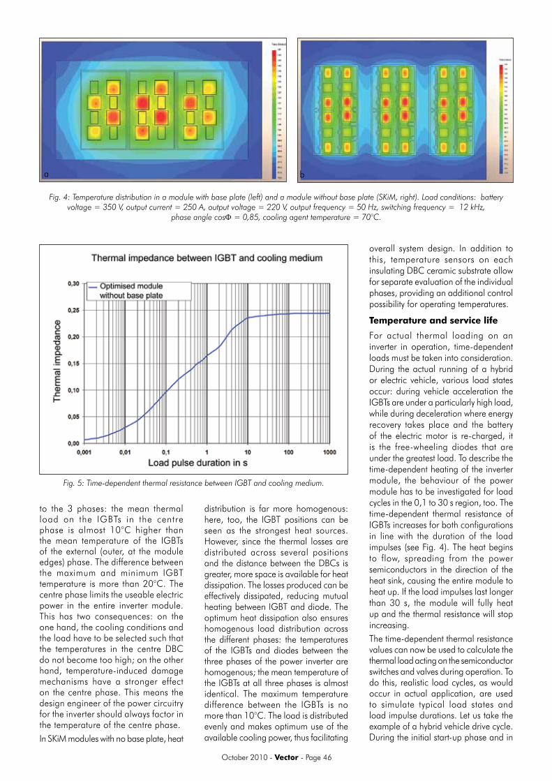
For actual thermal loading on an inverter in operation, time-dependent loads must be taken into consideration. During the actual running of a hybrid or electric vehicle, various load states occur: during vehicle acceleration the IGBTs are under a particularly high load, while during deceleration where energy recovery takes place and the battery of the electric motor is re-charged, it is the free-wheeling diodes that are under the greatest load. To describe the time-dependent heating of the inverter module, the behaviour of the power module has to be investigated for load cycles in the 0,1 to 30 s region, too. The time-dependent thermal resistance of IGBTs increases for both configurations in line with the duration of the load impulses (see Fig. 4). The heat begins to flow, spreading from the power semiconductors in the direction of the heat sink, causing the entire module to heat up. If the load impulses last longer than 30 s, the module will fully heat up and the thermal resistance will stop increasing. The time-dependent thermal resistance values can now be used to calculate the thermal load acting on the semiconductor switches and valves during operation. To do this, realistic load cycles, as would occur in actual application, are used to simulate typical load states and load impulse durations. Let us take the example of a hybrid vehicle drive cycle. During the initial start-up phase and in
a b
Fig. 4: Temperature distribution in a module with base plate (left) and a module without base plate (SKiM, right). Load conditions: battery voltage = 350 V, output current = 250 A, output voltage = 220 V, output frequency = 50 Hz, switching frequency = 12 kHz,
phase angle cosΦ = 0,85, cooling agent temperature = 70°C.
Fig. 5: Time-dependent thermal resistance between IGBT and cooling medium.

October 2010 - Vector - Page 47
the acceleration phases, energy is taken from the battery and fed to the electric motor. In these acceleration phases the power output reaches as much as 60 kW. The temperature of the IGBTs goes up to 95°C in line with inverter output. In phases of constant speed very little inverter power is needed, and the temperature of the semiconductors drops again. During deceleration the aim is for as much energy as possible to be recovered and fed back to the battery. Here, the power loss of both the IGBTs and the diodes is approximately the same, while the heat to be dissipated is at its highest, and the IGBTs reach almost 110°C.
The maximum temperature rise of the IGBTs is DT = 40°C. In terms of module service life, this is equivalent to 6-million load cycles (see Fig. 6). Just how important homogenous temperature distribution is for inverter service life and design can be seen if one looks at a temperature rise of just 10°C more – DT = 50°C – where the number of possible load cycles is 3 times lower at just 2-million cycles. To facilitate service life design and make optimum use of the semiconductors, the homogenous distribution of losses is an absolute must.
Conclusion
All in all, sintered modules with no base plate offer a series of possibilities for boosting the reliability of inverters in hybrid and electric vehicles. The disadvantages of solder connections and expansion caused by the base plate are eliminated. The optimised layout ensures a largely homogenous temperature dis t r ibut ion across the power semiconductors during operation. This means that in the service life expectation calculations all 3 phases may be considered in equal terms, facilitating inverter design. The reliability of the inverter, even under considerable active and passive temperature swings, is clearly improved. Testimony to this are the many different applications for sintered modules without base plate, such as in electric power-trains in cars and utility vehicles, as well as harsher applications such as racing cars.Contact Karen Schutte, Semikron, Tel 012 345-6060, [email protected]
Fig. 6: IGBT temperature curve during hybrid vehicle operation.
Fig. 7: Life cycle curve for load cycles in power modules. Homogenous temperature distribution is a must. A 10°C increase in temperature rise reduces the number of load cycles
by a factor of 3; a 20°C increase reduces the service life by a factor of 6.