power quality improvement using a shunt active power ... 7 no 5/power... · international...
TRANSCRIPT

International Electrical Engineering Journal (IEEJ)
Vol. 7 (2016) No.5, pp. 2266-2278
ISSN 2078-2365
http://www.ieejournal.com/
2266 Halawa et. al., Power Quality Improvement Using a Shunt Active Power Filter Based on the Hysteresis Current Controller
Abstract— one of the main power quality concerns currently is
the existence of harmonics. Shunt active power filters are
widely applied in power distribution grids to mitigate current
harmonics and compensate the reactive power. In this paper
the instantaneous reactive power theory is used to detect
reference compensation current for the controller of the shunt
active filter and a hysteresis current controller is used to
synthesize it precisely. Hysteresis current controller is one of
the simplest current control methods and the most popular one
for active power filter applications, but it suffers from an
uneven switching frequency, to overcome this disadvantage a
novel fuzzy hysteresis current controller is being used. The
proposed controller is characterized by simplicity as a result of
reducing the size of calculations that makes it acting faster and
doesn’t rely on the load parameters. The system was modeled
and simulated using MATLAB/SIMULINK. The results of
simulation are presented and discussed they show the
effectiveness of the proposed fuzzy hysteresis controller in
improving the PWM performance and thus improve the shunt
active power filter performance.
Index Terms— Shunt Active Power Filters, p-q theory,
Hysteresis Band Current Controller, Fuzzy Logic, Harmonic
Distortion
I. INTRODUCTION
Ideally an electricity supply should fixedly show a perfectly
sinusoidal voltage signal at every customer location. However,
for a number of reasons, utilities often find it difficult to
maintain such desirable condition [1.2]. For example the
widespread use of nonlinear devices likes (microprocessor,
variable speed drives, uninterrupted power supplies and
electronic lighting) which have become used on a large scale.
These modern power electronic devices draw a significant
amount of harmonics from the electrical grid; these non
sinusoidal currents interact with the impedance of the power
distribution lines creating voltage distortion at the point of
common coupling (PCC) that can affect both the distribution
system equipment and the user loads connected to it. As a
result, the utilities obliged to reduce the total harmonic
distortion (THD) at the point of common coupling below 5%
as given in the IEEE 519-1992 harmonic standard. This can
be achieved through the use of the harmonic filters whether
passive or active filters [3-5]. The passive filtering is the
simplest classical solution to mitigate the harmonic distortion,
these filters consisting of R, L and C elements connected in
various configurations. Although simple, these filters have
many defects such as fixed compensation, bulky size and
resonance so these filters may not be able to achieve the
desired performance thus we need to use dynamic and
adjustable devices to mitigate the power quality problems
such as active power filters [6,7]. Active power filters are
considered the most ideal solutions to the many of power
quality problems such as harmonics, reactive power, regulate
terminal voltage, flicker and improve voltage balance in three
phase systems. Shunt active power filter is the most important
configuration and widely used in active power line
conditioners applications. It automatically adapts to changes
in the grid and load fluctuations, can compensate for several
harmonic orders and eliminating the risk of resonance
between the filter and the grid impedance [8-14].
II. SHUNT ACTIVE POWER FILTER
Shunt active power filter based on voltage source converter
(VSC) is an effective solution to current harmonics, reactive
power and current unbalance. The basic principle of this filter
is to use power electronics technologies to generate particular
currents components that can cancel the current harmonic
components from non linear load [15-17].
The performance of the shunt active filter depends on the
reference compensating current detection algorithm and the
current control technique used to drive the gating pulses of the
active power filter switches to generate compensating current
that should be injected into the power system to mitigate the
current harmonics and compensate the reactive power
[18-22].
The compensation characteristics of the shunt APF are shown
in Fig. 1
Power Quality Improvement Using a
Shunt Active Power Filter Based on the
Hysteresis Current Controller
Mohamed Halawa1, Belal Abou-Zalam2, Abdel-Azem Sobaih3
1,2,3Industrial Electronics and Control Engineering Department, Faculty of Electronic Engineering, Menoufia University, Egypt
M7alawa @gmail.com

International Electrical Engineering Journal (IEEJ)
Vol. 7 (2016) No.5, pp. 2266-2278
ISSN 2078-2365
http://www.ieejournal.com/
2267 Halawa et. al., Power Quality Improvement Using a Shunt Active Power Filter Based on the Hysteresis Current Controller
Fig.1 Basic configuration of a shunt active filter
III. INSTANTANEOUS REACTIVE POWER THEORY
Estimation of reference compensating current can be done
through two main approaches, time domain and frequency
domain approach. A time domain method uses the
conventional concepts of circuit analysis and algebraic
transformations that require less calculation, thus simplifying
the control function, in the opposite the frequency domain
methods require a large amount of calculations and a lot of
memory [23]
Reactive power theory is the most commonly used time
domain methods where it is very efficient and flexible in
designing controllers for active power filters. It’s based on a
set of instantaneous powers defined in the time domain, thus
allowing the controller of the active filters to operate in real
time. The following steps are used to calculate current
harmonic components of the load current that are used as a
reference signal for the shunt active power filter controller
[24-26].
Step 1: transform the three phase load currents and phase
voltages from the a-b-c coordinates to 0 coordinates
by:
1 11
2 2 2
3 3 30
2 2
a
b
c
ii
ii
i
(1)
1 11
2 2 2
3 3 30
2 2
a
b
c
vv
vv
v
(2)
Step 2: calculate the values of the instantaneous real and
imaginary powers by:
p v i v i (3)
q v i v i (4)
Step 3: for this step, as shown in Fig. 2. The high pass filter is
used to extract the oscillating components of real power.
P P
Fig.2 The high pass filter used to extract the ac component of p
Step 4: The compensated currents produced by the shunt APF
in coordinates are;
*
2 2*
1
-
c
c
i v v p
v v qv vi
(5)
Step 5: these currents are transformed from coordinates
to the a-b-c coordinates that are used as a reference signal for
active power filter controller:
*
*
*
*
*
1 0
2 1 3
3 2 2
1 3
2 2
ca
c
cb
c
cc
ii
ii
i
(6)
IV. HYSTERESIS CURRENT CONTROL
Current controller is the most critical part for the shunt
active power filter performance that drawn more attention
from industry and researchers [27]. It force power circuit of
the shunt active filter to synthesize the compensating current
precisely by drive the gating pulses of the active power filter
switches [28].
There are various current control methods such as PI
control, sinusoidal PWM and hysteresis control. Hysteresis
current controller has proven to be the most suitable for all the
application of current controlled voltage source converters in
shunt active power filters [29-33]. It derives the switching
signals of the active power filter switches by comparing the
current error signal with a constant hysteresis band as shown
in Fig. 3
HPF

International Electrical Engineering Journal (IEEJ)
Vol. 7 (2016) No.5, pp. 2266-2278
ISSN 2078-2365
http://www.ieejournal.com/
2268 Halawa et. al., Power Quality Improvement Using a Shunt Active Power Filter Based on the Hysteresis Current Controller
Fig. 3 a constant hysteresis band current control loop
The current controller is designed to the three phases and
the switching logic for each phase is developed as follows
[5,23,34-36].
If the error current exceeds the upper limit of the hysteresis
band, the upper switch of the inverter arm is turned off and the
lower switch is turned on, As a result, the current starts to
decay. If the error current crosses the lower limit of the band ,
the lower switch is turned off and the upper switch is turned
on. As a result, the current gets back into the hysteresis band.
The main problem when applying the conventional
hysteresis band current controller is its uneven switching
frequency and that leads to audio noises, high switching losses,
injection of high frequency ripple current to the system and
difficulty in designing suitable filters to remove these high
frequency components. To avoid these unsatisfactory features
adaptive hysteresis band has been recommended in the
literature [37-44] to control the modulation frequency.
Fig. 4 PWM current and voltage waves with hysteresis band current control
Fig. 4. Shows current and voltage waves of the PWM-voltage
source inverter for phase a. The behavior of the switching
can be divided into two components over one switching
period, as follows:
1) During the switching period (t1):
The current ramps from lower hysteresis band –HB to the
upper hysteresis band +HB and the inverter side voltage
is 0.5 dcv
1(0.5 - ( )) a
dc s
div v t
dt L
(7)
2) During the switching period (t2):
The currents ramps from upper hysteresis band +HB to the
lower hysteresis band -HB and the inverter side voltage is -0.5
vdc
-1
(0.5 ( ))adc s
div v t
dt L (8)
From the geometry of Figure 4, we can write
*
1 1 2a adi dit t HB
dt dt
(9)
*
2 2 2a adi dit t HB
dt dt
(10)
1 2
1s
sw
t t Tf
(11)
Where t1 and t2 are the respective switching intervals, and
swf is the modulation frequency Adding (9) and (10) and
substituting (11), we can write:
*
1 2
10a a a
sw
di di dit t
dt dt f dt
(12)
Subtracting (10) from (9), we get *
1 2 1 24 ( )a a adi di diHB t t t t
dt dt dt
(13)
Substituting (8) in (13)
*
1 2 1 24 ( ) ( )a adi diHB t t t t
dt dt
(14)
Substituting (8) in (12) and simplifying *
1 2( )
a
sw a
di dtt t
f di dt (15)
Substituting (15) in (14), gives
2
2
0.125 ( )4[ (1 ( ))]dc s
sw dc
v v tLHB S
f L v L (16)
Where fsw is the switching frequency; 0.5 vdc is half of the
total bus voltage; L is the output load inductor; vs(t) is the
supply voltage; S is the slope of reference current and HB is
the hysteresis band.
The adaptive HB should be derived instantaneously during

International Electrical Engineering Journal (IEEJ)
Vol. 7 (2016) No.5, pp. 2266-2278
ISSN 2078-2365
http://www.ieejournal.com/
2269 Halawa et. al., Power Quality Improvement Using a Shunt Active Power Filter Based on the Hysteresis Current Controller
each sample time to keep the switching frequency remains
nearly constant, this can be achieved with the help of fuzzy
logic controller as stated In literature [20,23,45,46]. which S
and vs(t) are taken as input variables to the fuzzy controller
and the HB is the output. But if the reference current is
assumed to be smooth, the following equations can be written
in the switching intervals t1 and t2:
1
0.5 - ( )2 dc sv v tHB
t L (17)
2
- 0.5 - ( )-2 dc sv v tHB
t L (18)
Combining (17) and (18) and solving for the switching period
T gives:
2 2
2
(0.25 ( ))
dc
dc s
LHBvT
v v t
(19)
2 2(0.25 ( ))
2
dc ssw
dc
v v tf
LHBv
(20)
For a fixed hysteresis band current controller the
parameters of equation (02) are constant except for the supply
voltage that changes over each fundamental cycle causing
uneven switching frequency for the voltage source converter,
ttherefore, if HB can be varied in response to vs (t) a constant
switching frequency can be achieved [47,48]. In next section
fuzzy logic based adaptive hysteresis current controller will
help to fix the switching frequency.
V. THE PROPOSED FUZZY LOGIC FOR
HYSTERESIS CURRENT CONTROLLER
The fuzzy logic controller is one of the advantageous
control methods for systems facing difficulties in obtaining
mathematical models or having performance restrictions with
traditional linear control methods. In a fuzzy logic controller,
the control signal is determined from the assessment of a set
of linguistic rules (if-then rules), these rules are obtained from
our understanding of the process to be controlled. To design
fuzzy controller, variables that can represent the dynamic
performance of the system to be controlled must be taken as
the inputs to the controller [49]. Subsequently the supply
voltage vS(t) and its derivative ∆ vS(t) are chosen as inputs to
the fuzzy controller, and the hysteresis band (HB) is taken as
the output as shown in Fig. 5
Fig.5 The proposed fuzzy hysteresis band current controller
VI. SIMULATION RESULTS
This section introduce the details of simulations that have
been implemented using MATLAB/SIMULINK, to shows
the performance of the proposed shunt active power filter to
mitigate the current harmonics and compensate reactive
power in the distribution grid. Test system that was used to
carry out the analysis consists of a three-phase diode bridge
rectifier with RL load Connected to three-phase three wire
distribution system and shunt active power filter connected to
the system by an inductor L. The control strategy of the shunt
active filter based on p-q theory to generate the reference
compensation current, hysteresis band current controller to
drive the gating signals of the shunt active filter switches and
PI controller to regulate the voltage of dc side capacitor of the
shunt active filter. The values of the circuit components used
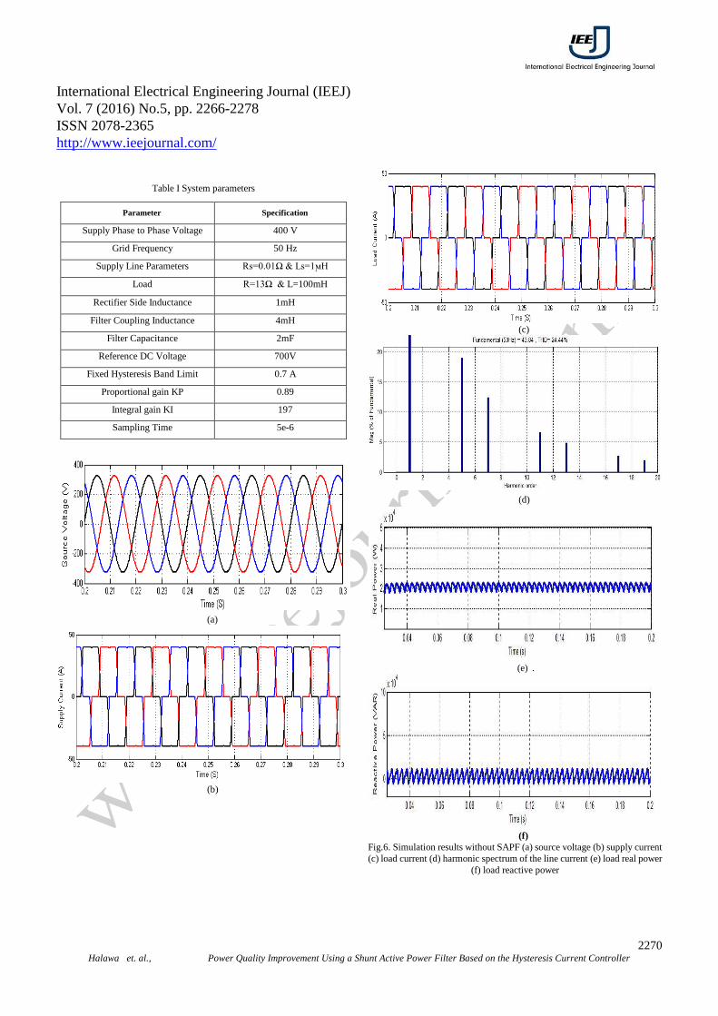
in the simulation are given in Table I. The system
performance was analyzed without the shunt active filter and
Fig. 6 gives the details of source voltage, source current, load
current, harmonic spectrum of the supply current, real and
reactive power supplied by the source to the load. It is seen
that line current is distorted due to nonlinear load and the total
harmonic distortion (THD) of the supply current is 24.44%,
this current distortion resulting from the dominance of 5th, 7th,
11th and 13th harmonic spectral components. Real and reactive
power supplied from the source to the load have constant
values and a superposition of oscillating components, These
oscillating components are related to the presence of
harmonics.
International Electrical Engineering Journal (IEEJ)
Vol. 7 (2016) No.5, pp. 2266-2278
ISSN 2078-2365
http://www.ieejournal.com/
2270 Halawa et. al., Power Quality Improvement Using a Shunt Active Power Filter Based on the Hysteresis Current Controller
Table I System parameters
Parameter Specification
Supply Phase to Phase Voltage 400 V
Grid Frequency 50 Hz
Supply Line Parameters Rs=0.01Ω & Ls=1ϻH
Load R=13Ω & L=100mH
Rectifier Side Inductance 1mH
Filter Coupling Inductance 4mH
Filter Capacitance 2mF
Reference DC Voltage 700V
Fixed Hysteresis Band Limit 0.7 A
Proportional gain KP 0.89
Integral gain KI 197
Sampling Time 5e-6
(a)
(b)
(c)
(d)
(e) .
(f)
Fig.6. Simulation results without SAPF (a) source voltage (b) supply current
(c) load current (d) harmonic spectrum of the line current (e) load real power
(f) load reactive power

International Electrical Engineering Journal (IEEJ)
Vol. 7 (2016) No.5, pp. 2266-2278
ISSN 2078-2365
http://www.ieejournal.com/
2271 Halawa et. al., Power Quality Improvement Using a Shunt Active Power Filter Based on the Hysteresis Current Controller
A. PERFORMANCE OF FIXED HYSTERESIS
BAND CURRENT CONTROLLER BASED
SAPF
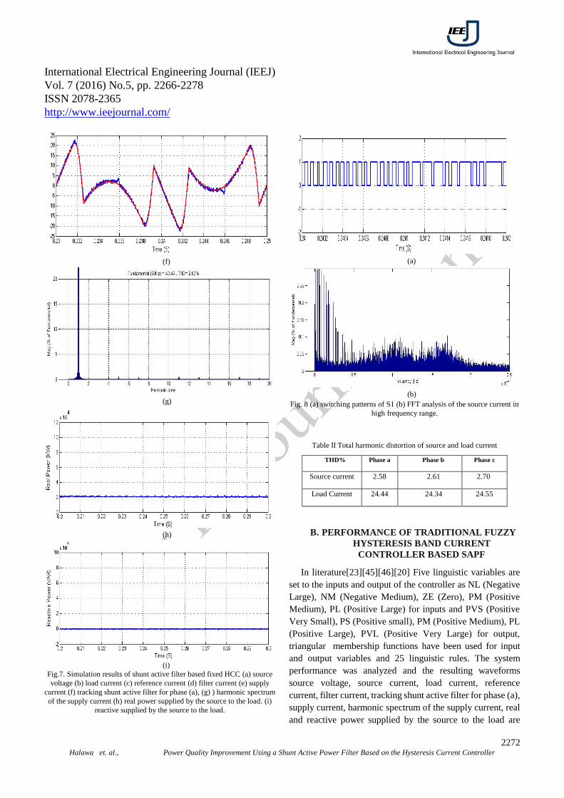
The system performance was analyzed and the resulting
waveforms source voltage, source current, load current,
reference current, filter current, tracking shunt active filter for
phase (a), supply current, harmonic spectrum of the supply
current, real and reactive power supplied by the source to the
load are shown in Fig. 7(a)-(i) respectively. As shows the
shunt active power filter (SAPF) shows a good filtering
process which leads to compensate harmonic components
from the source current, as it is clear from Table II and
harmonic spectrum analysis of the supply current, THD of the
source current has decreased from 24.44% to 2.63% that is
less than 5% which is in compliance with IEEE 519-1992
standard for harmonics under non linear loads. As well shows
the undesired portions of the real and reactive power of the
load that related to the presence of harmonics have been
compensated by the SAPF and the source supplies only
fundamental real power and zero reactive power to the load.
In spite of that when applying the conventional hysteresis
band current controller the Shunt APF operates in uneven
switching frequency as it is shown in Fig. 8. This uneven
switching frequency Leads to audio noises, high switching
losses, injection of high frequency ripple current to the system
and makes the design of suitable filters to remove these high
frequency components is difficult, difficulty in determining
convenient switching device and calculate its switching
losses. To avoid these unsatisfactory features, adaptive
hysteresis band current controller with the changeable
hysteresis band will be used based on the fuzzy logic.
(a)
(b)
(c)
(d)
(e)
International Electrical Engineering Journal (IEEJ)
Vol. 7 (2016) No.5, pp. 2266-2278
ISSN 2078-2365
http://www.ieejournal.com/
2272 Halawa et. al., Power Quality Improvement Using a Shunt Active Power Filter Based on the Hysteresis Current Controller
(f)
(g)
(h)
(i)
Fig.7. Simulation results of shunt active filter based fixed HCC (a) source
voltage (b) load current (c) reference current (d) filter current (e) supply
current (f) tracking shunt active filter for phase (a), (g) ) harmonic spectrum
of the supply current (h) real power supplied by the source to the load. (i)
reactive supplied by the source to the load.
(a)
(b)
Fig. 8 (a) switching patterns of S1 (b) FFT analysis of the source current in
high frequency range.
Table II Total harmonic distortion of source and load current
THD% Phase a Phase b Phase c
Source current 2.58 2.61 2.70
Load Current 24.44 24.34 24.55
B. PERFORMANCE OF TRADITIONAL FUZZY
HYSTERESIS BAND CURRENT
CONTROLLER BASED SAPF
In literature[23][45][46][20] Five linguistic variables are
set to the inputs and output of the controller as NL (Negative
Large), NM (Negative Medium), ZE (Zero), PM (Positive
Medium), PL (Positive Large) for inputs and PVS (Positive
Very Small), PS (Positive small), PM (Positive Medium), PL
(Positive Large), PVL (Positive Very Large) for output,
triangular membership functions have been used for input
and output variables and 25 linguistic rules. The system
performance was analyzed and the resulting waveforms
source voltage, source current, load current, reference
current, filter current, tracking shunt active filter for phase (a),
supply current, harmonic spectrum of the supply current, real
and reactive power supplied by the source to the load are
International Electrical Engineering Journal (IEEJ)
Vol. 7 (2016) No.5, pp. 2266-2278
ISSN 2078-2365
http://www.ieejournal.com/
2273 Halawa et. al., Power Quality Improvement Using a Shunt Active Power Filter Based on the Hysteresis Current Controller
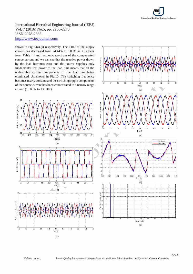
shown in Fig. 9(a)-(i) respectively. The THD of the supply
current has decreased from 24.44% to 3.03% as it is clear
from Table III and harmonic spectrum of the compensated
source current and we can see that the reactive power drawn
by the load becomes zero and the source supplies only
fundamental real power to the load, this means that all the
undesirable current components of the load are being
eliminated. As shown in Fig.10. The switching frequency
becomes nearly constant and the switching ripple components
of the source current has been concentrated to a narrow range
around (10 KHz to 13 KHz)
(a)
(b)
(c)
(d)
(e)
(f)
(g)

International Electrical Engineering Journal (IEEJ)
Vol. 7 (2016) No.5, pp. 2266-2278
ISSN 2078-2365
http://www.ieejournal.com/
2274 Halawa et. al., Power Quality Improvement Using a Shunt Active Power Filter Based on the Hysteresis Current Controller
(h)
(i)
Fig.9. Simulation results of traditional fuzzy HCC (a) source voltage (b) load
current (c) reference current (d) filter current (e) supply current (f) tracking
shunt active filter for phase (a), (g) ) harmonic spectrum of the supply current
(h) real power supplied by the source to the load. (i) reactive supplied by the
source to the load.
Table III Total harmonic distortion of source and load currents
THD% Phase a Phase b Phase c
Source current 2.99 3.10 3.02
Load Current 24.44 24.34 24.55
(a)
(b)
Fig. 12 (a) switching patterns of S1 (b) FFT analysis of the source current in
high frequency range.
C. PERFORMANCE OF PROPOSED FUZZY
HYSTERESIS BAND CURRENT
CONTROLLER BASED SAPF
Three linguistic variables are set to the inputs and output of
the controller as NL (Negative Large), ZE (Zero), PL
(Positive Large) for inputs and PS (Positive small), PM
(Positive Medium), PL (Positive Large) for output, triangular
membership functions as shown in Fig. 11, have been used for
input and output variables because of its simplicity, the fuzzy
rules are given in Table IV. Fig. 12 (a)-(e) highlights the
performance of proposed fuzzy hysteresis current controller,
gives the details of source voltage, source current, load
current, reference current, filter current, tracking shunt active
filter for phase (a), supply current, harmonic spectrum of the
supply current, real and reactive power supplied by the source
to the load. The THD of the supply current has decreased
from 24.44% to 2.66% as it is clear from Table V and
harmonic spectrum of the compensated source current and the
undesired portions of the real and reactive powers of the load
that related to the presence of harmonics have been
compensated by the SAPF and the source supplies only
fundamental real power and zero reactive power to the load. It
is seen from Fig. 13, that the switching frequency becomes
nearly constant and the switching ripple components of the
source current has been concentrated to a narrow range
around (15 KHz), this means that the proposed fuzzy
hysteresis band current controller has worked properly and
the modulation frequency of the shunt active power filter is
held in 15 KHz, Hence select the appropriate filter to mitigate
the ripple components in the filter current, determine
convenient switching device and calculate switching losses
has become easier.
Table IV Fuzzy inference rule
Vs (t)
PL Z NL

International Electrical Engineering Journal (IEEJ)
Vol. 7 (2016) No.5, pp. 2266-2278
ISSN 2078-2365
http://www.ieejournal.com/
2275 Halawa et. al., Power Quality Improvement Using a Shunt Active Power Filter Based on the Hysteresis Current Controller
∆ Vs (t)
PL PS PS PS
Z PM PL PM
NL PS PS PS
(a)
(b)
(c)
Fig. 11 Membership functions of the input variables and output variable
(a) Source voltage (b) rate of change of source voltage (c) hysteresis
band
(a)
(b)
(c)
(d)
(e)

International Electrical Engineering Journal (IEEJ)
Vol. 7 (2016) No.5, pp. 2266-2278
ISSN 2078-2365
http://www.ieejournal.com/
2276 Halawa et. al., Power Quality Improvement Using a Shunt Active Power Filter Based on the Hysteresis Current Controller
(f)
(g)
(h)
(i)
Fig.10. simulation results of proposed fuzzy HCC (a) source voltage (b) load
current (c) reference current (d) filter current (e) supply current (f) tracking
shunt active filter for phase (a), (g) ) harmonic spectrum of the supply current
(h) real power supplied by the source to the load. (i) reactive supplied by the
source to the load.
Table V Total harmonic distortion of source and load currents
THD% Phase a Phase b Phase c
Source current 2.67 2.64 2.69
Load Current 24.44 24.34 24.55
(a)
(b)
Fig. 13 (a) switching patterns of S1 (b) FFT analysis of the source current in
high frequency range.
VII. RESULTS AND ANALYSIS
The results obtained from the simulation is given in table
VII .It shows that the three current controllers, fixed HCC,
Traditional fuzzy HCC and Proposed fuzzy HCC have been
found to meet the IEEE 519-1992 standard for harmonics
under nonlinear loads where THD is less than 5% at the point
of common coupling, with the following observations:
The proposed fuzzy HCC gets better compensation
than traditional fuzzy HCC.
The modulation frequency is held nearly fixed with
Traditional fuzzy HCC and got constant more
and more using the proposed fuzzy HCC contrary
to fixed HCC.
The proposed fuzzy HCC acts faster than
traditional Fuzzy HCC as a result of the use of
simplified calculations (9 rules instead of 25
rules)

International Electrical Engineering Journal (IEEJ)
Vol. 7 (2016) No.5, pp. 2266-2278
ISSN 2078-2365
http://www.ieejournal.com/
2277 Halawa et. al., Power Quality Improvement Using a Shunt Active Power Filter Based on the Hysteresis Current Controller
The proposed fuzzy HCC forces the compensating
current to track the reference compensation
current more accurately.
The proposed fuzzy HCC characterized by
removing reliance on variable parameters like
reference current that is detected from load
parameters and uses only fixed parameters like
supply voltage that does not change in a real
system.
Table VII Summary of total harmonic distortion of source current and
switching frequency for each current controller
Current Control
Technique
THD % Switching Frequency
(KHz) Without Filter 24.44
FHCC 2.63 10:18
Traditional fuzzy HCC 3.03 10:13
Proposed fuzzy HCC 2.66 15
VIII. CONCLUSION
Shunt active power filter is the most effective solution to
mitigate the current harmonics and compensate the reactive
power. In this paper a novel current control strategy based on
fuzzy logic for shunt APF was introduced to improve the
current controller technique that is the backbone of the shunt
active power filter operation. The simulation results have
verified the effectiveness of this new technique to fix the
modulation frequency of the shunt active power filter
compared to the conventional current controller where the
modulation frequency changing over a wide range causing
many of undesirable effects.
REFERENCES
[1] S. Pal, P. S. Bondriya, and Y. Pahariya, “MATLAB-Simulink
Model Based Shunt Active Power Filter Using Fuzzy Logic
Controller to Minimize the Harmonics,” Int. J. Sci. Res. Publ., vol.
3, no. 12, pp. 7–11, 2013.
[2] D. Prathyusha and P. Venkatesh, “UVTG Control Strategy for
Three Phase Four Wire UPQC to Improve Power Quality,” Int.
Electr. Eng. J., vol. 6, no. 9, pp. 1988–1993, 2015.
[3] S. F. Mekhamer and S. M. Ismael, “Sources and Mitigation of
Harmonics in Industrial Electrical Power Systems : State of the
Art,” Online J. Power Energy Eng., vol. 3, no. 4, pp. 320–332,
2012.
[4] W. M. Grady and S. Santoso, “Understanding power system
harmonics,” IEEE Power Eng. Rev., vol. 21, pp. 8–11, 2001.
[5] A. N. Jog and N. G. Apte, “An adaptive hysteresis band current
controlled shunt active power filter,” 5th Int. Conf. Compat.
Power Electron. CPE 2007, pp. 8031–8040, 2007.
[6] Z. Salam, P. C. Tan, and A. Jusoh, “Harmonics mitigation using
active power filter: a technological review,” Elektrika, vol. 8, no.
2, pp. 17–26, 2006.
[7] A. Teke, L. Saribulut, M. E. Meral, and M. Tümay, “Active Power
Filter : Review of Converter Topologies and Control Strategies,”
Gazi Univ. J. Sci., vol. 24, no. 2, pp. 283–289, 2011.
[8] B. Singh, K. Al-haddad, S. Member, and A. Chandra, “A Review
of Active Filters for Power Quality Improvement,” IEEE Trans.
Ind. Electron., vol. 46, no. 5, pp. 960–971, 1999.
[9] A. Martins, J. Ferreira, and H. Azevedo, “Active Power Filters for
Harmonic Elimination and Power Quality Improvement,” in
Power Quality, 2011, pp. 162–182.
[10] C. Veeresh, “Shunt Active Filter for Power Quality Improvement,”
Int. J. Eng. Res. Gen. Sci., vol. 3, no. 4, pp. 136–148, 2015.
[11] E. Mhawi, H. Daniyal, and M. H. Sulaiman, “Advanced
Techniques in Harmonic Suppression via Active Power Filter : A
Review,” Int. J. Power Electron. Drive Syst., vol. 6, no. 2, 2015.
[12] J. L. Afonso, J. G. Pinto, and H. Gonçalves, “Active Power
Conditioners to Mitigate Power Quality Problems in Industrial
Facilities,” in Power Quality Issues, 2013, pp. 105–138.
[13] S. Chourasiya and S. Agarwal, “A REVIEW : Control Techniques
for Shunt Active Power Filter for Power Quality Improvement
from Non-Linear Loads,” Int. Electr. Eng. J., vol. 6, no. 10, pp.
2028–2032, 2015.
[14] P. A. Prasad, N. V. V Ramesh, and L. V Narasimharao, “Modified
Three-Phase Four-Wire UPQC Topology with Reduced DC-Link
Voltage Rating,” Int. Electr. Eng. J., vol. 6, no. 2, pp. 1749–1755,
2015.
[15] F. Z. Peng, “Application issues of active power filters,” Ind. Appl.
Mag. IEEE, vol. 4, no. 5, pp. 21–30, 1998.
[16] G. Adam, A. G. S. Baciu, and G. Livinţ, “a matlab-simulink
approach to shunt active power filters,” in 25th European
Conference on Modelling and Simulation, 2011, vol. 6, no. Cd,
pp. 2–7.
[17] M. Kale and E. Özdemir, “Harmonic and reactive power
compensation with shunt active power filter under non-ideal
mains voltage,” Electr. Power Syst. Res., vol. 74, no. 3, pp.
363–370, Jun. 2005.
[18] A. G. Prasad and A. N. Kumar, “Comparison of Control
Algorithms for Shunt Active Filter for Harmonic Mitigation,” Int.
J. Eng. Res. Technol., vol. 1, no. 5, pp. 1–6, 2012.
[19] Z. Chelli, R. Toufouti, A. Omeiri, and S. Saad, “Hysteresis Control
for Shunt Active Power Filter under Unbalanced Three-Phase
Load Conditions,” J. Electr. Comput. Eng., vol. 2015, pp. 1–9,
2015.
[20] P. Rathika and D. Devaraj, “Fuzzy Logic – Based Approach for
Adaptive Hysteresis Band and Dc Voltage Control in Shunt Active
Filter,” Int. J. Comput. Electr. Eng., vol. 2, no. 3, pp. 404–412,
2010.
[21] K. Sebasthirani and K. Porkumaran, “Efficient Control of Shunt
Active Power Filter with Self- Adaptive Filter Using Average
Power Algorithm,” Int. J. Emerg. Technol. Adv. Eng., vol. 3, no. 5,
pp. 3–8, 2013.
[22] C. Salim and B. M. Toufik, “Intelligent Controllers for Shunt
Active Filter to Compensate Current Harmonics Based on SRF
and SCR Control Strategies,” Int. J. Electr. Eng. Informatics, vol.
3, no. 3, pp. 372–393, 2011.
[23] P. Rathika, “A Novel Fuzzy—Adaptive Hysteresis Controller
Based Three Phase Four Wire-Four Leg Shunt Active Filter for
Harmonic and Reactive Power Compensation,” Energy Power
Eng., vol. 03, no. 04, pp. 422–435, 2011.
[24] S. Saddam and P. J. Patel, “A Literature Review and Industrial
Survey on Active Power Filter,” Int. J. Eng. Dev. Res. (, vol. 2, no.
1, pp. 118–125, 2014.
[25] S. Mikkili, “Instantaneous Active and Reactive Power and Current

International Electrical Engineering Journal (IEEJ)
Vol. 7 (2016) No.5, pp. 2266-2278
ISSN 2078-2365
http://www.ieejournal.com/
2278 Halawa et. al., Power Quality Improvement Using a Shunt Active Power Filter Based on the Hysteresis Current Controller
Strategies for Current harmonics cancellation in 3-ph 4wire SHAF
With both PI and Fuzzy Controllers,” Energy Power Eng., vol. 03,
no. 03, pp. 285–298, 2011.
[26] N. Eskandarian, Y. A. Beromi, and S. Farhangi, “Improvement of
Dynamic Behavior of Shunt Active Power Filter Using Fuzzy
Instantaneous Power Theory,” J. Power Electron., vol. 14, no. 6,
pp. 1303–1313, Nov. 2014.
[27] C. C. Azevedo, R. L. a Ribeiro, C. B. Jacobina, and R. M. Sousa,
“DC-link regulator for Shunt Power Active Filter using
feed-forward control strategy,” in XI Brazilian Power Electronics
Conference, 2011, no. 1, pp. 877–883.
[28] A. Hirofumi, H. W. Edson, and A. Mauricio, instantaneous power
theory and applications to power conditioning. the Institute of
Electrical and Electronics Engineers,Inc, 2007.
[29] H. Vahedi, E. Pashajavid, and K. Al-Haddad, “Fixed-band
fixed-frequency hysteresis current control used in APFs,” in
IECON Proceedings (Industrial Electronics Conference), 2012,
pp. 5944–5948.
[30] S. M. Abedi and H. Vahedi, “Simplified calculation of adaptive
hysteresis current control to be used in active power filter,” Trends
Appl. Sci. Res, vol. 8, pp. 46–54, 2012.
[31] K. P. K.Sebasthirani, “performance enhancement of shunt active
power filter with fuzzy and hysteresis controllers,” J. Theor. Appl.
Inf. Technol., vol. 60, no. 2, pp. 284–291, 2014.
[32] C. Rejil and A. K. R, “Design and Simulation of Three Phase
Shunt Active Power Filter Using SRF Theory,” Adv. Electron.
Electr. Eng., vol. 3, no. 6, pp. 651–660, 2013.
[33] S. Anjana and P. Maya, “Fuzzy Logic Control of Shunt Active
Power Filter for Power Quality Improvement,” in Proceedings of
the International Conference on Soft Computing Systems, 2015,
pp. 975–985.
[34] P. V. R. Kumar and M. S. Kalavathi, “Fuzzy Based Hysteresis
Current Controlled Shunt Active Power Filter for Power
Conditioning,” Int. J. Mod. Eng. Res., vol. 3, no. 1, pp. 477–485,
2013.
[35] P. S. S. Hadpe, M. P. Bhawalkar, N. B. Shaikh, and K. P. Varade,
“Variable Hysteresis Band Current Controller for Power
Harmonics Compensation,” Int. J. Emerg. Technol. Adv. Eng.,
vol. 3, no. 4, pp. 426–431, 2013.
[36] G. Jayakrishna, “Fuzzy Logic Control based Three Phase Shunt
Active Filter for Voltage Regulation and Harmonic Reduction,”
Int. J. Comput. Appl., vol. 10, no. 5, pp. 13–19, 2010.
[37] H. Vahedi and a Sheikholeslami, “Variable hysteresis current
control applied in a shunt active filter with constant switching
frequency,” 2010 1st Power Qual. Conferance, PQC 2010, 2010.
[38] H. Vahedi, Y. R. Kukandeh, M. G. Kashani, A. Dankoob, and A.
Sheikholeslami, “Comparison of adaptive and fixed-band
hysteresis current control considering high frequency harmonics,”
2011 IEEE Appl. Power Electron. Colloquium, IAPEC 2011, pp.
185–188, 2011.
[39] B. K. Bose, “An Adaptive Hy steresis-Band Current Control
Technique of a Voltage-Fed PWM Inverter for Machine Drive
System,” IEEE Trans. Ind. Electron., vol. 31, no. 5, pp. 402–408,
1990.
[40] H. Vahedi, A. Sheikholeslami, M. Tavakoli Bina, and M. Vahedi,
“Review and simulation of fixed and adaptive hysteresis current
control considering switching losses and high-frequency
harmonics,” Adv. Power Electron., vol. 2011, no. 2011, pp. 1–6,
2011.
[41] M. Kale and E. Ozdemir, “An adaptive hysteresis band current
controller for shunt active power filter,” Electr. Power Syst. Res.,
vol. 73, no. 2, pp. 113–119, Feb. 2005.
[42] K. P and K. K. Mahapatra, “PI and fuzzy logic controllers for shunt
active power filter — A report,” ISA Trans., vol. 51, no. 1, pp.
163–169, 2012.
[43] K. Pitchaivijaya and K. Mahapatra, “Adaptive-Fuzzy Controller
Based Shunt Active Filter for Power Line Conditioners,”
TELKOMNIKA, vol. 9, no. 2, pp. 203–210, 2011.
[44] S. Hassan, “Implementation of Adaptive Hysteresis Current
Controlled Shunt Active Filter For Non-Linear Loads,” Int. J.
Innov. Res. Electr. Electron. Instrum. Control Eng., vol. 2, no. 2,
pp. 1089–1093, 2014.
[45] B. M. A. F. MEKRI, “Fuzzy Hysteresis Control and Parameter
OptFimization of a Shunt Active Power Filter,” J. Inf. Sci. Eng.,
vol. 1156, pp. 1139–1156, 2005.
[46] M. B. B. Sharifian, R. Rahnavard, and Y. Ebrahimi, “Variable
Hysteresis Band Current Controller of Shunt Active Filter Based
Fuzzy logic Theory under Constant Switching Frequency,” Int. J.,
vol. 1, no. 2, pp. 236–244, 2009.
[47] S. M. A. and H. Vahedi, “Simplified Calculation of Adaptive
Hysteresis Current Control To Be Used In Active Power Filter,”
Trends Appl. Sci. Res., vol. 8, no. 1, pp. 46–54, 2013.
[48] D. G. Holmes, R. Davoodnezhad, and B. P. McGrath, “An
improved three-phase variable-band hysteresis cuegularrent
Regulator,” IEEE Trans. Power Electron., vol. 28, no. 1, pp.
441–450, 2013.
[49] R. Manikanta and S. Chaitanya, “A Fuzzy Logic Based
D-STATCOM Topology with Reduced VSI Rating, DC Link
Voltage and Filter Size,” Int. Electr. Eng. J., vol. 5, no. 10, pp.
1586–1593, 2014.