power quality improvement using d-statcom with pi … · power quality improvement using d-statcom...
TRANSCRIPT

Power Quality Improvement Using D-STATCOM withPI and Fuzzy Logic ControllerBanothu Raju1*, Fatima Azra2
AbstractIt was observed from the literature Survey that, the field of power quality and custom power devices plays animportant role in power system. The electronic devices are very sensitive to disturbances and become lesstolerant to power quality problems such as voltage sags, swells and harmonics. Voltage dips are consideredto be one of the most severe disturbances to the industrial equipments .The major problems dealt here is thevoltage sag and swell. To solve this problem, custom power devices are used. One of those devices is theD-STATCOM, which is the most efficient and effective modern custom power device used in power distributionnetworks. DSTATCOM injects a current in to the system to correct the voltage sag and swell. A IGBT basedVSC is used. A PWM method is used to generate pulses for IGBT. VSC with pulse-width modulation (PWM)offers fast and reliable control for voltage dips mitigation. The proposed D-STATCOM is modeled and simulatedusing MATLAB/SIMULINK software. The D-STATCOM is controlled using Synchronous Reference Frame Theory(SRF) using the PI controller.
KeywordsDistribution Static Compensator (D-STATCOM), Fuzzy Inference Systems (FIS), Proportional Integral (PI),Synchronous Reference Frame Theory (SRF), Voltage Sag, Voltage swell, MATLAB
1PG Scholar, Dept.of EEE, JBIT.2Assistant Professor, Dept.of EEE, JBIT.Corresponding author: [email protected], [email protected]
Contents
1 Introduction 1
2 Basic Concepts 12.1 D-STATCOM . . . . . . . . . . . . . . . . . . . . . . . . . . 2
3 Proportional Integral (PI) Controller 2
4 Fuzzy Inference System (FIS) 2
5 Modeling Simulation and It’s Re¬sults 3
6 concusion 4
References 4
1. IntroductionPower quality is one of major concern in the present era. Ithas become important, especially, with the introduction ofsophisticated devices, whose performance is very sensitiveto the quality of power supply.The power quality problemis an occurrence manifested as a nonstandard voltage,current or frequency that results in a failure of end userequipments [1]. Power quality problems comprise a widerange of disturbances such as voltage sags/swells, flicker,harmonics, distortion, impulse, transient and interrup-tions. Among this problem, voltage sag is the most com-monly occurring problems in terms of power quality prob-
lems. The IEC electro technical vocabulary, IEC 60050-604, 1998 defines a voltage sag as any “sudden reductionof the voltage at a point in the electrical system, followedby voltage recovery after a short period of time, from halfa cycle to a few seconds”. Likewise, in more explicitly,A sag, as defined by IEEE Standard 1159, IEEE Recom-mended Practice for Monitoring Electric Power Quality,is “a decrease in RMS voltage or current at the power fre-quency for durations from 0.5 cycles to 1 minute, reportedas the remaining voltage”. Typical values are between0.1 p.u. and0. 9 p.u. Typical fault clearing times rangefrom three to thirty cycles depending on the fault currentmagnitude and the type of over current detection andinterruption. Actually, Voltage sags are appearing due tofaults, motor starting , and transformer energizing. D-STATCOM includes lower cost, smaller size, and its fastdynamic response to the disturbance. [2]. The importanceof this paper is to resolve voltage sag and swell problemmanifested in voltage deviations that result in failure ofcustomer equipment and to present the model of the cus-tom power device, namely, D-STATCOM and its controlapplication to mitigate voltage sag/swell.
2. Basic Concepts
International Journal of Computational Science, Mathematics and EngineeringVolume 3, Issue.9, 2016
ISSN-2349-8439
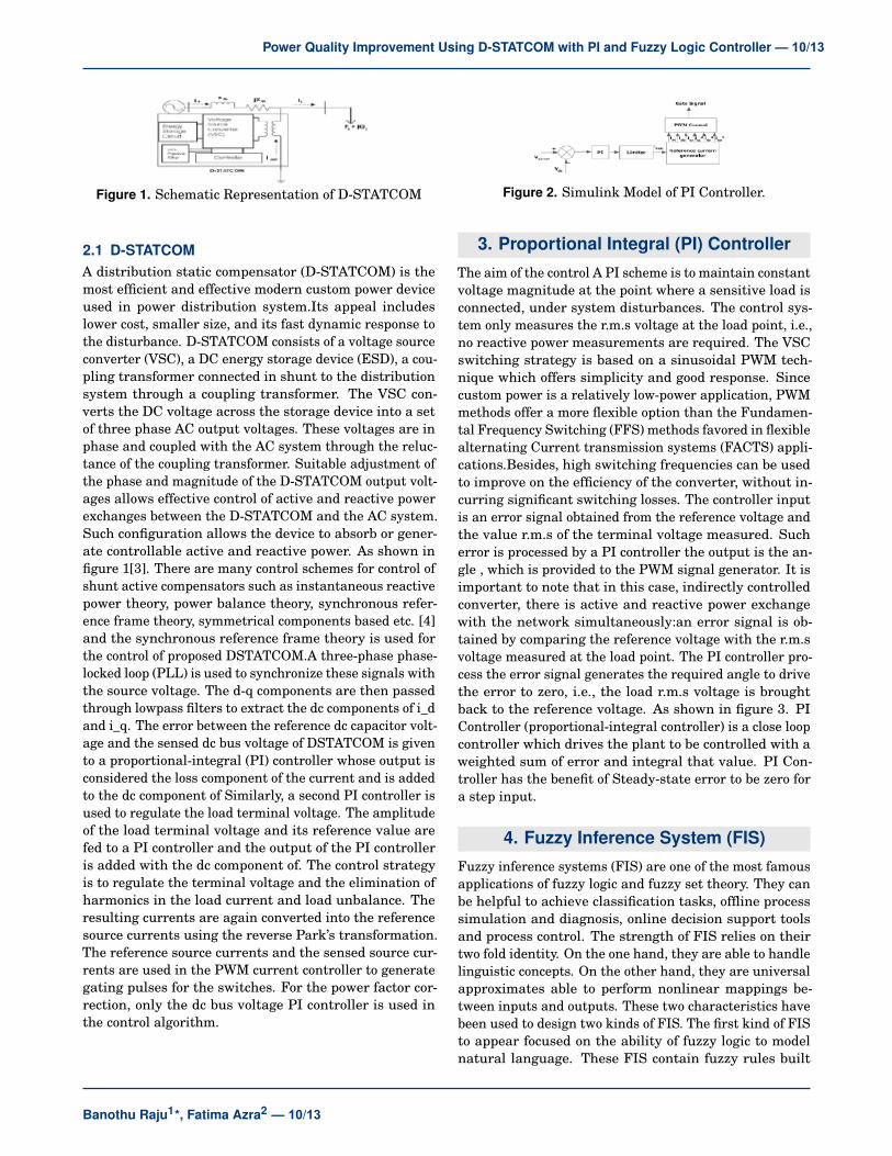
Figure 1. Schematic Representation of D-STATCOM
2.1 D-STATCOMA distribution static compensator (D-STATCOM) is themost efficient and effective modern custom power deviceused in power distribution system.Its appeal includeslower cost, smaller size, and its fast dynamic response tothe disturbance. D-STATCOM consists of a voltage sourceconverter (VSC), a DC energy storage device (ESD), a cou-pling transformer connected in shunt to the distributionsystem through a coupling transformer. The VSC con-verts the DC voltage across the storage device into a setof three phase AC output voltages. These voltages are inphase and coupled with the AC system through the reluc-tance of the coupling transformer. Suitable adjustment ofthe phase and magnitude of the D-STATCOM output volt-ages allows effective control of active and reactive powerexchanges between the D-STATCOM and the AC system.Such configuration allows the device to absorb or gener-ate controllable active and reactive power. As shown infigure 1[3]. There are many control schemes for control ofshunt active compensators such as instantaneous reactivepower theory, power balance theory, synchronous refer-ence frame theory, symmetrical components based etc. [4]and the synchronous reference frame theory is used forthe control of proposed DSTATCOM.A three-phase phase-locked loop (PLL) is used to synchronize these signals withthe source voltage. The d-q components are then passedthrough lowpass filters to extract the dc components of i_dand i_q. The error between the reference dc capacitor volt-age and the sensed dc bus voltage of DSTATCOM is givento a proportional-integral (PI) controller whose output isconsidered the loss component of the current and is addedto the dc component of Similarly, a second PI controller isused to regulate the load terminal voltage. The amplitudeof the load terminal voltage and its reference value arefed to a PI controller and the output of the PI controlleris added with the dc component of. The control strategyis to regulate the terminal voltage and the elimination ofharmonics in the load current and load unbalance. Theresulting currents are again converted into the referencesource currents using the reverse Park’s transformation.The reference source currents and the sensed source cur-rents are used in the PWM current controller to generategating pulses for the switches. For the power factor cor-rection, only the dc bus voltage PI controller is used inthe control algorithm.
Figure 2. Simulink Model of PI Controller.
3. Proportional Integral (PI) Controller
The aim of the control A PI scheme is to maintain constantvoltage magnitude at the point where a sensitive load isconnected, under system disturbances. The control sys-tem only measures the r.m.s voltage at the load point, i.e.,no reactive power measurements are required. The VSCswitching strategy is based on a sinusoidal PWM tech-nique which offers simplicity and good response. Sincecustom power is a relatively low-power application, PWMmethods offer a more flexible option than the Fundamen-tal Frequency Switching (FFS) methods favored in flexiblealternating Current transmission systems (FACTS) appli-cations.Besides, high switching frequencies can be usedto improve on the efficiency of the converter, without in-curring significant switching losses. The controller inputis an error signal obtained from the reference voltage andthe value r.m.s of the terminal voltage measured. Sucherror is processed by a PI controller the output is the an-gle , which is provided to the PWM signal generator. It isimportant to note that in this case, indirectly controlledconverter, there is active and reactive power exchangewith the network simultaneously:an error signal is ob-tained by comparing the reference voltage with the r.m.svoltage measured at the load point. The PI controller pro-cess the error signal generates the required angle to drivethe error to zero, i.e., the load r.m.s voltage is broughtback to the reference voltage. As shown in figure 3. PIController (proportional-integral controller) is a close loopcontroller which drives the plant to be controlled with aweighted sum of error and integral that value. PI Con-troller has the benefit of Steady-state error to be zero fora step input.
4. Fuzzy Inference System (FIS)Fuzzy inference systems (FIS) are one of the most famousapplications of fuzzy logic and fuzzy set theory. They canbe helpful to achieve classification tasks, offline processsimulation and diagnosis, online decision support toolsand process control. The strength of FIS relies on theirtwo fold identity. On the one hand, they are able to handlelinguistic concepts. On the other hand, they are universalapproximates able to perform nonlinear mappings be-tween inputs and outputs. These two characteristics havebeen used to design two kinds of FIS. The first kind of FISto appear focused on the ability of fuzzy logic to modelnatural language. These FIS contain fuzzy rules built
Banothu Raju1*, Fatima Azra2 — 10/13
Power Quality Improvement Using D-STATCOM with PI and Fuzzy Logic Controller — 10/13
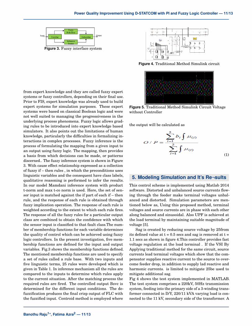
Figure 3. Fuzzy interface system
from expert knowledge and they are called fuzzy expertsystems or fuzzy controllers, depending on their final use.Prior to FIS, expert knowledge was already used to buildexpert systems for simulation purposes. These expertsystems were based on classical Boolean logic and werenot well suited to managing the progressiveness in theunderlying process phenomena. Fuzzy logic allows grad-ing rules to be introduced into expert knowledge basedsimulators. It also points out the limitations of humanknowledge, particularly the difficulties in formalizing in-teractions in complex processes. Fuzzy inference is theprocess of formulating the mapping from a given input toan output using fuzzy logic. The mapping, then providesa basis from which decisions can be made, or patternsdiscerned.. The fuzzy inference system is shown in Figure3. With cause effect relationship expressed as a collectionof fuzzy if – then rules , in which the preconditions useslinguistic variables and the consequent have class labels,qualitative reasoning is performed to infer the results.In our model Mamdani inference system with productt-norm and max t-co norm is used. Here, the set of sen-sor input is matched against the if part of each if – thenrule, and the response of each rule is obtained throughfuzzy implication operation. The response of each rule isweighted according to the extent to which each rule fires.The response of all the fuzzy rules for a particular outputclass are combined to obtain the confidence with whichthe sensor input is classified to that fault class.The num-ber of membership functions for each variable determinesthe quality of control which can be achieved using fuzzylogic controllers. In the present investigation, five mem-bership functions are defined for the input and outputvariables. Fig.3 shows the membership functions defined.The mentioned membership functions are used to specifya set of rules called a rule base. With two inputs andfive linguistic terms, 25 rules were developed which isgiven in Table 1. In inference mechanism all the rules arecompared to the inputs to determine which rules applyto the current situation. After the matching process therequired rules are fired. The controlled output Bsvc isdetermined for the different input conditions. The de-fuzzification produces the final crisp output of FLC withthe fuzzified input. Centroid method is employed where
Figure 4. Traditional Method Simulink circuit
Figure 5. Traditional Method Simulink Circuit Voltagewithout Controller
the output will be calculated as
(1)
5. Modeling Simulation and It’s Re¬sultsThis control scheme is implemented using Matlab 2014software. Distorted and unbalanced source currents flow-ing through the feeder make terminal voltages unbal-anced and distorted. Simulation parameters are men-tioned below as, Using this proposed method, terminalvoltages and source currents are in phase with each otheralong balanced and sinusoidal. Also UPF is achieved atthe load terminal by maintaining suitable magnitude ofvoltage [5].
Sag is created by reducing source voltage by 25fromits defined value at t = 0.5 secs and sag is removed at t =1.1 secs as shown in figure 4.This controller provides fastvoltage regulation at the load terminal . If the VSI ByApplying traditional method for the same circuit, sourcecurrents lead terminal voltages which show that the com-pensator supplies reactive current to the source to over-come feeder drop, in addition to supply lad reactive andharmonic currents. is limited to mitigate 25be used tomitigate additional sag.Fig 4 shows the test system implemented in MATLAB.The test system comprises a 220kV, 50Hz transmissionsystem, feeding into the primary side of a 3-winding trans-former connected in D/Y, 220/11 kVA varying load is con-nected to the 11 kV, secondary side of the transformer. A
Banothu Raju1*, Fatima Azra2 — 11/13
Power Quality Improvement Using D-STATCOM with PI and Fuzzy Logic Controller — 11/13

Figure 6. Traditional Method Simulink Circuit Voltagewith Conventional Controller
Figure 7. Traditional Method Simulink Circuit Voltagewith Conventional Controller THD
two-level DSTATCOM is connected to the 11 kV tertiarywinding to provide instantaneous voltage support at theload point. A 750 F capacitor on the dc side provides theDSTATCOM energy storage capabilities. To show theeffectiveness of this controller in providing continuousvoltage regulation, simulations were carried out with andwith no DSTATCOM connected to the system. Duringtransients this voltage deviates from its reference voltage,but returned back to its reference value once steady stateis reached. For the simulation study a three source istreated as primary distribution substation and the distri-bution line is treated as the lumped inductance in serieswith the resistance. Let us consider a fixed load is con-nected to the distribution line and a heavy inductive andcapacitive load is connected at required instants to studythe performance the D-STATCOM for the case of voltagesag conditions.
Source voltage is reduced to 50Percentage of the de-fined value which has the capability to mitigate deep sagby applying DSTATCOM. Load is increased to 120that thetraditional method gives less power factor without DSTAT-COM and can be improved by applying this DSTATCOM[6].
The voltage output waveforms are as shown in Fig-
Figure 8. Fuzzy Controller Based Simulation Circuit forProposed Converter
Figure 9. Fuzzy Controller for Proposed Converter
Figure 10. Fuzzy Controller Based Output Wave Form
ures.The proposed method is experimentally verified ona reduced scale set up. In this method the rms value ofsource current is reduced from 0.61 to 0.73 A and sourcecurrent is also reduced to 1.75 A from 1.84 A in this pro-posed
6. concusionIn this paper, a method has been proposed for the gen-eration of reference load voltage for a voltage controlledDSTATCOM . The performance of the proposed scheme iscompared with the traditional voltage controlled DSTAT-COM using linear and nonlinear load . The proposedmethod satisfies the following conditions such that main-tenance of UPF even at load changes, better voltage reg-ulation, losses are reduced in VSI. The simulation andexperimental results how that the proposed scheme pro-vides DSTATCOM, a capability to improve several PQproblems.The modelling of test system for voltage sagwithout D-STATCOM gives the output 15 and 85percent-age loss. The modeling of test system for voltage sag withD-STATCOM(PI control) gives the 91percentage outputand 9percentage loss. The modelling of test system forvoltage sag with D-STATCOM(fuzzy control) gives the95percentage output and 5percentage loss. The modellingof test system for voltage swell without D-STATCOMgives the output 80percentage and 20percentage loss.The modelling of test system for voltage swell with D-STATCOM(PI control) gives the 97percentage output and3percentage loss.
Figure 11. Fuzzy Controller Based Output Wave FormTHD Value Is Low
Banothu Raju1*, Fatima Azra2 — 12/13
Power Quality Improvement Using D-STATCOM with PI and Fuzzy Logic Controller — 12/13

References[1] M. Bollen. 2000. Understanding Power Quality Prob-
lems. Piscataway, NJ, USA: IEEE. 1: 1-35.[2] A. Ghosh and G. Ledwich. 2003. Load compensating
DSTATCOM in weak ac systems. IEEE Trans. PowerDel. 18(4): 1302-1309.
[3] A. Elnady and M. Salama. 2005. Unified approachfor mitigating voltage sag and voltage flicker usingthe DSTATCOM. IEEE Trans. Power Del. 20(2), pt. 1:992-1000.
[4] S. Rahmani, A. Hamadi and K. Al-Haddad. 2012. ALyapunov-function based control for a three-phaseshunt hybrid active filter. IEEE Trans. Ind. Electron.59(3): 1418-1429.
[5] M. K. Mishra and K. Karthikeyan. 2009. A fast-actingdc-link voltage controller for three-phase DSTATCOMto compensate ac and dc loads. IEEE Trans. PowerDel. 24(4): 2291-2299.
[6] M. K. Mishra, A. Ghosh and A. Joshi.2003. Operationof a DSTATCOM in voltage control mode. IEEE Trans.Power Del. 18(1): 258-264. A. Jain, K. Joshi, A. Behal,and N. Mohan. 2006. Voltage regulation with STAT-COMs: Modeling, control and results. IEEE Trans.Power Del. 21(2): 726-735.
[7] P. Mitra and G. Venayagamoorthy. 2010. An adaptivecontrol strategy for DSTATCOM applications in anelectric ship power system. IEEE Trans. Power Elec-tron. 25(1): 95-104.
Banothu Raju
Fatima Azra
IJCSME OPEN ACCESS
Banothu Raju1*, Fatima Azra2 — 13/13
Power Quality Improvement Using D-STATCOM with PI and Fuzzy Logic Controller — 13/13