power quality interface for low, medium and high voltage ... · pdf filethe state-of-the-art...
TRANSCRIPT

Type PQI-DA
ApplicationThe state-of-the-art PQI-DA Power Quality Interface for low, medium and high voltage networks is the main component of a system for carrying out all of the re-quired measurement tasks in electrical networks. The PQI-DA can be used as both a Power Quality Interface compliant to DIN EN 50160 and as a measurement de-vice for measuring all physically defined measurement quantities in AC electrical networks.The component is primarily designed to monitor special reference quantities and quality agreements between the energy supplier and the customer, as well as to re-cord, analyse and save the data.Modern voltage quality measurement devices operate according to the IEC 61000-4-30 standard. This stan-dard defines measurement methods and so provides the user with a basis for comparison.Devices from different manufacturers which function according to this standard must give approximately the same readings.The standard defines two measurement device classes.Class A measurement devices are used primarily for measurements related to contracts in customer/sup-plier relationships, while class B measurement devices can be used for determining statistical quality values. A class B device is sufficient for measurements according to EN 50160.
The PQI-DA complies with the requirements of IEC 610004- 30 for class A devices for the following para-meters.
Parameters Class• Accuracy of the voltage measurement A• Determination of the time intervals A• Marking of measurement values for events A• Harmonics, interharmonics A
Power Quality Interface for Low, Medium and High Voltage Networks
* As wall mounting housing* As DIN busbar housing
• Frequency A• Voltage asymmetry A• Event recording A• Synchronisation A (with DCF77or GPS)
In addition, three different fault-value recorders and/or fault recorders can be used.
The oscilloscope recorder stores fault records which are composed of 100 μs sampling values and whose length (information regarding the time period before and after the event) can be freely chosen.
The r.m.s. recorder stores fault records which are com-posed of the r.m.s. values of half period values (10 ms). The length of the fault record (information regarding the time period before and after the event) can also be freely chosen.
The harmonics recorder stores the corresponding harmonic spectrum of all harmonics from 2nd to 50th harmonic if a limit value (harmonic or THD of a voltage) is exceeded.
All fault records are triggered by events which can be freely defined. This enables phase-phase and phase-earth events to be recorded simultaneously.The signal voltage recorder records a freely-adjustable frequency (e.g. ripple control frequency) over a freely-selectable time range.Limit value violations can also be signalled via relays, if required.Various hardware versions are available for the input in-terface (U, I).
Current inputs for the measuring circuit (C20, C30) and for the protective circuit (C21, C31) are available.
GB
1 A. Eberle GmbH & Co. KG
Technical dataVersion 05/2008
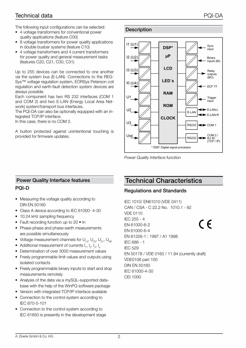
Power Quality Interface function
DescriptionThe following input configurations can be selected:• 4 voltage transformers for conventional power quality applications (feature C00)• 8 voltage transformers for power quality applications in double busbar systems (feature C10)• 4 voltage transformers and 4 current transformers for power quality and general measurement tasks (features C20, C21, C30, C31)
Up to 255 devices can be connected to one another via the system bus (E-LAN). Connections to the REG-Sys™ voltage regulation system, EORSys Peterson coil regulation and earth-fault detection system devices are always possible.Each component has two RS 232 interfaces (COM 1 and COM 2) and two E-LAN (Energy Local Area Net-work) system/transport bus interfaces.The PQI-DA can also be optionally equipped with an in-tegrated TCP/IP interface.In this case, there is no COM 2.
A button protected against unintentional touching is provided for firmware updates.
Power Quality Interface features
PQI-D
• Measuring the voltage quality according to DIN EN 50160• Class A device according to IEC 61000- 4-30• 10.24 kHz sampling frequency• Fault recording function up to 20 • In• Phase-phase and phase-earth measurements are possible simultaneously• Voltage measurement channels for U12, U23, U31, UNE
• Additional measurement of currents I1, I2, I3, Io• Determination of over 3000 measurement values• Freely programmable limit values and outputs using isolated contacts• Freely programmable binary inputs to start and stop measurements remotely• Analysis of the data via a mySQL-supported data- base with the help of the WinPQ software package• Version with integrated TCP/IP interface available• Connection to the control system according to IEC 870-5-101• Connection to the control system according to IEC 61850 is presently in the development stage
Technical CharacteristicsRegulations and Standards
IEC 1010/ EN61010 (VDE 0411)CAN / CSA - C 22.2 No. 1010.1 - 92VDE 0110IEC 255 - 4EN 61000-6-2EN 61000-6-4EN 61326-1 : 1997 / A1 1998IEC 688 - 1IEC 529EN 50178 / VDE 0160 / 11.94 (currently draft)VDE0106 part 100DIN EN 50160IEC 61000-4-30CEI 1000
Technical data PQI-DA
A. Eberle GmbH & Co. KG 2
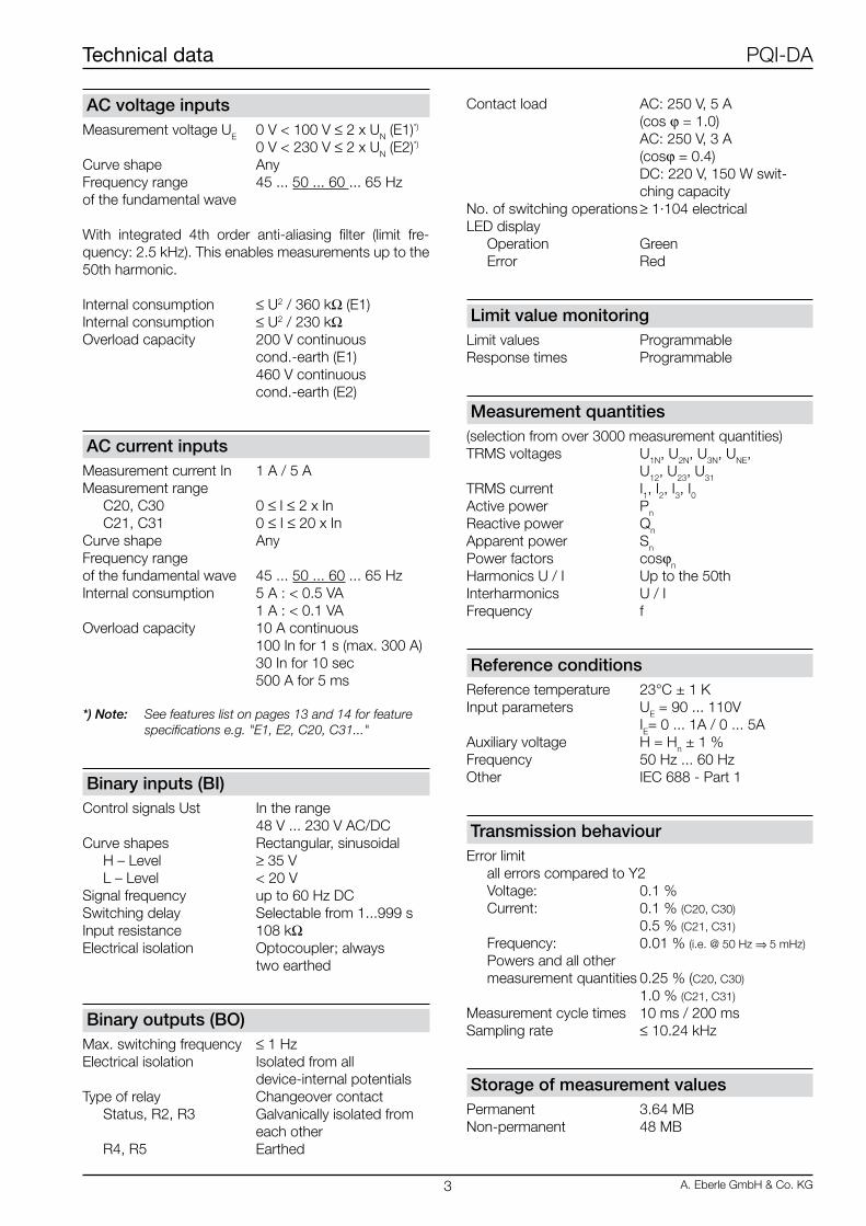
AC voltage inputsMeasurement voltage UE 0 V < 100 V ≤ 2 x UN (E1)*)
0 V < 230 V ≤ 2 x UN (E2)*)
Curve shape AnyFrequency range 45 ... 50 ... 60 ... 65 Hzof the fundamental wave
With integrated 4th order anti-aliasing filter (limit fre-quency: 2.5 kHz). This enables measurements up to the 50th harmonic.
Internal consumption ≤ U2 / 360 kΩ (E1)Internal consumption ≤ U2 / 230 kΩOverload capacity 200 V continuous cond.-earth (E1) 460 V continuous cond.-earth (E2)
AC current inputsMeasurement current In 1 A / 5 AMeasurement range C20, C30 0 ≤ I ≤ 2 x In C21, C31 0 ≤ I ≤ 20 x InCurve shape AnyFrequency rangeof the fundamental wave 45 ... 50 ... 60 ... 65 HzInternal consumption 5 A : < 0.5 VA 1 A : < 0.1 VAOverload capacity 10 A continuous 100 In for 1 s (max. 300 A) 30 In for 10 sec 500 A for 5 ms
*) Note: See features list on pages 13 and 14 for feature specifications e.g. "E1, E2, C20, C31..."
Binary inputs (BI)Control signals Ust In the range 48 V ... 230 V AC/DCCurve shapes Rectangular, sinusoidal H – Level ≥ 35 V L – Level < 20 VSignal frequency up to 60 Hz DCSwitching delay Selectable from 1...999 sInput resistance 108 kΩElectrical isolation Optocoupler; always two earthed
Binary outputs (BO)Max. switching frequency ≤ 1 HzElectrical isolation Isolated from all device-internal potentialsType of relay Changeover contact Status, R2, R3 Galvanically isolated from each other R4, R5 Earthed
Contact load AC: 250 V, 5 A (cos ϕ = 1.0) AC: 250 V, 3 A (cosϕ = 0.4) DC: 220 V, 150 W swit- ching capacityNo. of switching operations ≥ 1·104 electricalLED display Operation Green Error Red
Limit value monitoringLimit values ProgrammableResponse times Programmable
Measurement quantities(selection from over 3000 measurement quantities)TRMS voltages U1N, U2N, U3N, UNE, U12, U23, U31
TRMS current I1, I2, I3, I0Active power Pn
Reactive power Qn
Apparent power Sn
Power factors cosϕn
Harmonics U / I Up to the 50thInterharmonics U / IFrequency f
Reference conditionsReference temperature 23°C ± 1 KInput parameters UE = 90 ... 110V IE= 0 ... 1A / 0 ... 5AAuxiliary voltage H = Hn ± 1 %Frequency 50 Hz ... 60 HzOther IEC 688 - Part 1
Transmission behaviourError limit all errors compared to Y2 Voltage: 0.1 % Current: 0.1 % (C20, C30)
0.5 % (C21, C31)
Frequency: 0.01 % (i.e. @ 50 Hz ⇒ 5 mHz)
Powers and all other measurement quantities 0.25 % (C20, C30)
1.0 % (C21, C31)
Measurement cycle times 10 ms / 200 msSampling rate ≤ 10.24 kHz
Storage of measurement valuesPermanent 3.64 MBNon-permanent 48 MB
Technical data PQI-DA
3 A. Eberle GmbH & Co. KG

Test voltages Uaux COMs BO BI UE IE
Auxiliary voltage Uaux - 2.7 2.7 2.7 4.0 4.0
COMs, E-LAN, Time/Trigger BUS COMs 2.7 - 2.3 2.3 4.0 4.0
Binary outputs BO 2.7 2.3 - 2.3 4.0 4.0
Binary inputs (250 V) BI 2.7 2.3 2.3 - 4.0 4.0
Input voltage (E1, E2) UE 4.0 4.0 4.0 4.0 - 4.0
Input currents IE 4.0 4.0 4.0 4.0 4.0 -
Immunity to interference
CE conformity - Immunity to interference EN 61326 EN 61000-6-2 - Emitted interference EN 61326 EN 61000-6-4ESD IEC 61000-4-2 8 kV / 16 kV IEC 60 255-22-2
Electromagnetic fields IEC 61000-4-3 10 V/m IEC 60 255-22-3
Burst IEC 61000-4-4 4 kV / 2 kV IEC 60 255-22-4
Surge 1 MHz burst IEC 61000-4-5 4 kV / 2 kV IEC 61000-4-12 2.5 kV, class III IEC 60 255-22-1
Conducted high frequency magnetic fields IEC 61000-4-6 10 V, 150 kHz ... 80 MHz IEC 61000-4-8 100 A/m continuous All positions 1000 A/m 1 s
Voltage dips IEC 61000-4-11 30 % 0.02s, 60 % 1 s
Emitted interference EN 61326 EN 61000-6-4 - Housing At a distance of 10 m 30 ... 230 MHz, 40 dB 230 ... 1000 MHz, 47 dB - AC mains connection At a distance of 10 m 0.15 ... 0.5 MHz, 79 dB 0.5 ... 5 MHz, 73 dB 5 ... 30 MHz, 73 dB
Electrical safetyDegree of protection IDegree of pollution 2Measuring category III / 300 V optional III / 500 V
Operating voltages
50 V 230 V
E-LAN,COM-Server, COM1 ... COM2Time- / Trigger- BUS
Auxiliary voltageBinary inputsRelay outputs
Power supply
Feature H0 H1
AC (internal) - -
AC 85 … 264 V -
DC 88 … 280 V 18 … 72 V
Powerconsumption
≤ 15 VA ≤ 15 Watt
Frequency 45 … 20 mA -
Miniature fuse T2 250 V T2 250 V
The following applies to all features:Voltage interruptions ≤ 80 ms do not cause a fault or loss of data.
Note: All test voltages are AC voltages in kV, which may be applied for 1 minute. COM1, COM2 are tested against each other with 0.5 kV.
Technical data PQI-DA
A. Eberle GmbH & Co. KG 4

Dimensions
Ambient conditions
Temperature range Function -15 ... +55°C Transport und storage -25 ... +65°C
Humidity No condensation on 30 days/year 95 % rel.
Dry, cold IEC 60068-2-1 -15°C / 16 h
Dry, hot IEC 60068-2-2 +55°C / 16 h
Constant humid heat IEC 60068-2-3 + 40 °C/93 % / 2 days
Cyclical humid heat IEC 60068-2-30 12+12h, 6 cycles, +55°C/93%
Toppling IEC 60068-2-31 100 mm drop, unwrapped
Vibration IEC 60255-21-1 Class 1
Impact IEC 60255-21-2 Class 1
Data storageDevice settings Serial EEPROM with ≥ 1000 k read/write cyclesRAM data Li battery laser-welded
Mechanical Design
HousingThe PQI-DA Power Quality Interface has a robust stain-less steel housing.All connections are accessible via Phoenix terminals.All connections apart from the current and voltage in-puts are plug/clamping connections.If the COM server (feature T1) option is selected, an RJ 45 connection is available.
The device can be used for wall mounting as well as busbar mounting.
Material Stainless steelDegree of protection Housing IP 40 Terminals IP 20Weight ≤ 2 kgDimensions See figure belowConnection elements Screw terminals
Technical data PQI-DA
5 A. Eberle GmbH & Co. KG
Terminal strip no.
Description FunctionTerminal
no.Assignment
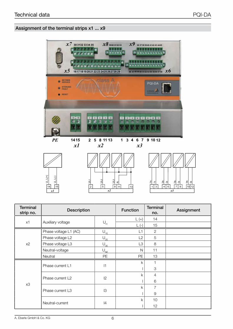
x1 Auxiliary voltage UH
L (+) 14
L (-) 15
x2
Phase voltage L1 (AC) U1E L1 2
Phase voltage L2 U2E L2 5
Phase voltage L3 U3E L3 8
Neutral-voltage UNE N 11
Neutral PE PE 13
x3
Phase current L1 I1k 1
l 3
Phase current L2 I2k 4
l 6
Phase current L3 I3k 7
l 9
Neutral-current I4k 10
l 12
Assignment of the terminal strips x1 ... x9
Technical data PQI-DA
A. Eberle GmbH & Co. KG 6

Terminal strip no.
Description FunctionTerminal
no.Assignment
x5
Status R1Pole
NC contactNO contact
161718
Not programmable
Binary outputs 230 V
R2Pole
NC contactNO contact
192021
Freely programmable
R3Pole
NC contactNO contact
222324
Freely programmable
R4Pole
NC contactNO contact
272625
Freely programmable
R5Pole
NC contactNO contact
272829
Freely programmable
x7 Binary inputs (230 V)
E1 + 30 Freely programmable
E2 + 31 Freely programmable
E1 / E2 GND 32
E3 + 33 Freely programmable
E4 + 34 Freely programmable
E3 / E4 GND 35
x9
E-LAN R (on the right) E- 36
E+ 37
EA- 38
EA+ 39
GND 40
E-LAN L (on the left) E- 41
E+ 42
EA- 43
EA+ 44
GND 45
Technical data PQI-DA
7 A. Eberle GmbH & Co. KG
Terminal strip no.
Description FunctionTerminal
no.Assignment
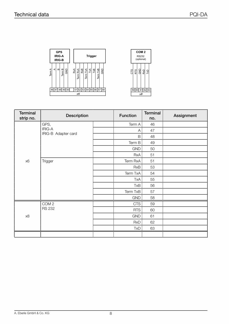
x6
GPS,IRIG-AIRIG-B Adapter card
Term A 46
A 47
B 48
Term B 49
GND 50
RxA 51
Trigger Term RxA 51
RxB 53
Term TxA 54
TxA 55
TxB 56
Term TxB 57
GND 58
x8
COM 2RS 232
CTS 59
RTS 60
GND 61
RxD 62
TxD 63
Technical data PQI-DA
A. Eberle GmbH & Co. KG 8

Serial interfacesRS232 interfacesEach PQI-DA has two RS 232 interfaces designated COM 1 and COM 2.COM 1 can be used as a parameterisation and pro-gramming interface via a 9-pole SUB-D plug.COM 2 can be wired via a plug-in terminal block.If option T1 (COM server / TCP/IP) is selected, an RJ 45 connection is available instead of COM 2.
Connection elementsCOM 1 Pin strip, Sub Min D on the front of the device, pin assignment as on PC
COM 2 Terminal strip x8
Connection options PC, terminal, modem, PLC
Number of data bits/ Parity 8, even, off, oddprotocol
Transfer rate bit / s 1200, 2400, 4800, 9600, 19200, 38400, 57600, 76800, 115200
Handshake RTS / CTS or XON / XOFF
TCP/IPThe TCP/IP or COM server interface is galvanically isola-ted from all other electrical circuits.Communication via this interface is possible with a baud rate of 100 MBaud.Parameterisation of the connection (IP address etc.) is carried out using the WinPQ parameterisation software.
RS485 InterfacesEach PQI-DA is equipped with a double E-LAN interface as standard. It provides the bus connection to PQI-DAs, REG-D voltage regulators, REG-DP Petersen coil regu-lators, or an EORSys earth fault locating system.
E-LAN (Energy - Local Area Network)Features• 255 bus stations can be addressed• Multimaster structure• Integrated repeater function• Open ring, bus or combination of bus and ring possible• Log based on SDLC/HDLC framework• Transfer rates of 62.5 or 125 kbit/s• Telegram length 10 to 30 Bytes• Average throughput approx. 100 telegrams / s
Hardware-orientated device versionsThe flexibility of the system, i.e. precisely matching spe-cific requirements, can also be achieved using the hard-ware characteristics of the input and output configura-tion.Table 1 shows the different possibilities.
Measurement inputs
Feature
C00 4 voltage inputs (100 V / 230 V)
C10 2 x 4 voltage inputs (100 V / 230 V) for double busbar system
C20 to C31 4 voltage inputs (100 V / 230 V),4 current inputs (1 A / 5 A)
Table 1
Technical data PQI-DA
9 A. Eberle GmbH & Co. KG

Application Examples (a selection)
Feature group “C” has 5 typical applications.
Technical data PQI-DA
A. Eberle GmbH & Co. KG 10

Block diagram for features C20, C21, C30, C31
Technical data PQI-DA
11 A. Eberle GmbH & Co. KG

Block diagram for feature C10
Technical data PQI-DA
A. Eberle GmbH & Co. KG 12

CHARACTERISTIC CODEPower Quality Interfacefor medium and high voltage systemsaccording to DIN EN-50160 und IEC 61000-4-30 (class A)with 4 binary in- and outputs plus life-contactwith two E-LAN interfaces for communication withother REGSys- components like REG-D(A), PAN-D, REG-DP(A)as wall- and/or DIN-rail mounting enclosure (204x142x132) mm
PQI-DA
Power Supply:AC 85V..110V..264V oder DC 88V..220V..280V
DC 18V...60V...72VH0H1
Input Configuration:
4 VTs adn 4CTs4 VTs adn 4CTs4 VTs adn 4CTs4 VTs adn 4CTs
4 VTs2 x 4 VTs
Ir =1A (Imax < 2 x Ir) Ir =1A (Imax < 20 x Ir)
Ir =5A (Imax < 2 x Ir) Ir =5A (Imax < 20 x Ir)
C00C10C20C21C30C31
Additional Interface:as RS 232 (COM 2)
as COM-Server (RJ 45)
T0T1
Rated Input Values:100/110V230/400V
other rated values (e.g. 4 x 100V and 4 x 400V) Please note: E9 can only be chosen together with C10!!
E1E2E9
Binary Inputs:
4 programable binary inputs (AC/DC 48…250V)4 programable binary inputs (DC 10…48V)
4 programable binary inputs with other input voltages
M1M2M9
Operating Manual: GermanEnglish
FrenschSpanish
Italian
G1G2G3G4G5
Ordering informationWhen ordering please note:• Only one code with the same capital letter is possible• If the capital letter is followed by the number 9, additional details in plain text are required• If the capital letter is followed by 0, the code can be omitted.
Technical data PQI-DA
13 A. Eberle GmbH & Co. KG
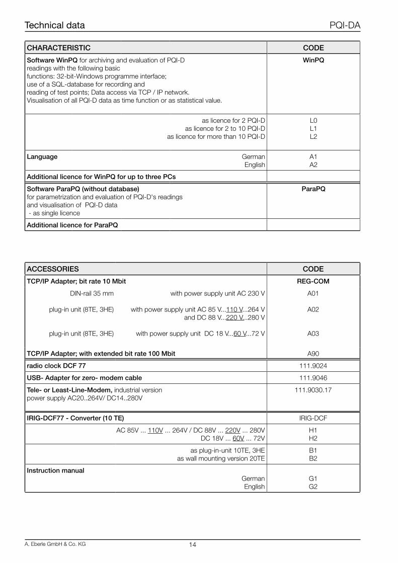
CHARACTERISTIC CODE
Software WinPQ for archiving and evaluation of PQI-Dreadings with the following basicfunctions: 32-bit-Windows programme interface;use of a SQL-database for recording andreading of test points; Data access via TCP / IP network.Visualisation of all PQI-D data as time function or as statistical value.
WinPQ
as licence for 2 PQI-Das licence for 2 to 10 PQI-D
as licence for more than 10 PQI-D
L0L1L2
Language GermanEnglish
A1A2
Additional licence for WinPQ for up to three PCs
Software ParaPQ (without database)for parametrization and evaluation of PQI-D's readingsand visualisation of PQI-D data - as single licence
ParaPQ
Additional licence for ParaPQ
ACCESSORIES CODE
TCP/IP Adapter; bit rate 10 Mbit REG-COM
DIN-rail 35 mm
plug-in unit (8TE, 3HE)
plug-in unit (8TE, 3HE)
with power supply unit AC 230 V
with power supply unit AC 85 V...110 V...264 Vand DC 88 V...220 V...280 V
with power supply unit DC 18 V...60 V...72 V
A01
A02
A03
TCP/IP Adapter; with extended bit rate 100 Mbit A90
radio clock DCF 77 111.9024
USB- Adapter for zero- modem cable 111.9046
Tele- or Least-Line-Modem, industrial version power supply AC20..264V/ DC14..280V
111.9030.17
IRIG-DCF77 - Converter (10 TE) IRIG-DCF
AC 85V ... 110V ... 264V / DC 88V ... 220V ... 280V DC 18V ... 60V ... 72V
H1H2
as plug-in-unit 10TE, 3HEas wall mounting version 20TE
B1B2
Instruction manualGermanEnglish
G1G2
Technical data PQI-DA
A. Eberle GmbH & Co. KG 14

Notes: .....................................................................................................................
................................................................................................................................
................................................................................................................................
................................................................................................................................
................................................................................................................................
................................................................................................................................
................................................................................................................................
................................................................................................................................
................................................................................................................................
................................................................................................................................
................................................................................................................................
................................................................................................................................
................................................................................................................................
................................................................................................................................
................................................................................................................................
................................................................................................................................
................................................................................................................................
................................................................................................................................
................................................................................................................................
................................................................................................................................
................................................................................................................................
................................................................................................................................
................................................................................................................................
................................................................................................................................
................................................................................................................................
................................................................................................................................
................................................................................................................................
................................................................................................................................
................................................................................................................................
................................................................................................................................
................................................................................................................................
................................................................................................................................
Technical data PQI-DA
15 A. Eberle GmbH & Co. KG
T627D201-04.INDD
Technical data PQI-DA
A. Eberle GmbH & Co. KG 16
Presented by:A.Eberle GmbH & Co. KG
Aalener Str. 30/32D-90441 NürnbergPhone: +49 (0) 911 / 62 81 08-0Fax: +49 (0) 911 / 62 81 08 96
http://[email protected]
Subject to change.The most recent version of this datasheet can be found on http://www.a-eberle.de.