power sources utility: 60 hz - 120/240 v - 1,2,3 phase fixed voltage batteries fuel cells photo...
TRANSCRIPT

Power Sources
• Utility: 60 Hz - 120/240 V - 1,2,3 Phase• Fixed Voltage Batteries• Fuel Cells• Photo Voltaic • Thermionic Generators• AC generators (“Alternators”) – variable frequency• DC Generators

Electrical Consumption
• AC motors – sync/async• DC Motors• Residential Heating/Cooling• Lighting AC/DC High frequency• Induction Heating HF• Electronic Systems – Fixed Voltage DC• Transmission Losses• Conversion Losses
Replacement of Legacy Technologies
• Automotive (Electric Vehicle Propulsion)• Hydraulic controls (Fly by wire)• Tele - commuting, tele - presence• Beam Weapons• Unmanned Aircraft

Critical Converter Parameters
• Efficiency• Weight• Size/Volume• Power handling Capacity• Power Density• Cost

Photo-voltaic Cells

UsN Type DopantsP Type Dopants

P
N
PN Junction
Diode Doping Profile
P
N
Diffusion Result
Depletion Region
Hole Diffusion
Electron Diffusion
+ + + + + +
+ + + + + +
- - - - - -
- - - - - -
Equilibrium Charge
Displacement
Internal E-FieldResulting from
ChargeDisplacement Inhibits
Further Diffusion
- Photon Generated Hole/Electron Pair
E- Field Accelerates Electron and Hole
ISS
(Proportional to
photon flux)
Equivalent effect of photon generated internal current.
+

Resistive Load
-
VSS
+
ISS
(Proportional to
photon flux)
0.0260 1
SSV
vJI I e
0
0.026 ln 1JSS
IV v
I
IJ
L SS JI I I
Shockley’s Equation:
Photo-voltaic Cell
SS
L
V
R
VSS
IJ

P VI
PI
V
Hyperbolic Curve
P1
P2 > P1
0.578 1.4 0.83
0.5780.403
1.4
Opt
Opt
P v A W
vR
A
To get maximum power out of the photovoltaic cell, the converter must make the cells see 0.403 ohms when ISS = 1.5 amps!
Power Converter
Load:R = ?
Photovoltaic Array
To make matters worse, POpt and ROpt vary with temperature as well as ISS!

Maximum Power Condition: Curves are Tangent
0.0260
0.0260 0
1SS
SS
VOptv
L SS J SSSS
V
vSS SS Opt
PI I I I I e
V
V I I e I P
0.02602
20.0260
0.026
0.026
SS
SS
VOptvL
SS SS
V
vSSOpt
PIdIe
dV v V
V Ie P
v
20.026 0.0260
0 0
0 0
0.026
0.026 0.0260.026 ln 1 0.026 ln
0.026
SS SSV V
v vSSSS SS
SS SSSS
SS SS
V IV I I e I e
v
I Iv vV v v
I V V V I
… which converges to ~ 0.1% in 4 or 5 iterations, but will be ~ 0.6 V for almost any reasonable conditions . . . so to hell with the math!

In full sunlight, the solar energy flux is ~ 1Kw/m2, and 15% efficiency is normal, so
2150Opt CellwP A
m 250
0.6Opt
SS Cell
PI A
v
ISS in amperes, ACell in m2.
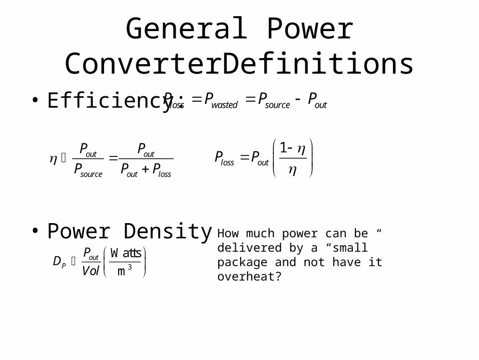
General Power ConverterDefinitions
• Efficiency:
• Power Density
loss wasted source outP P P P
out out
source out loss
P P
P P P
1loss outP P
3
Watts
mout
P
PD
Vol
How much power can be delivered by a “small” package and not have it overheat?
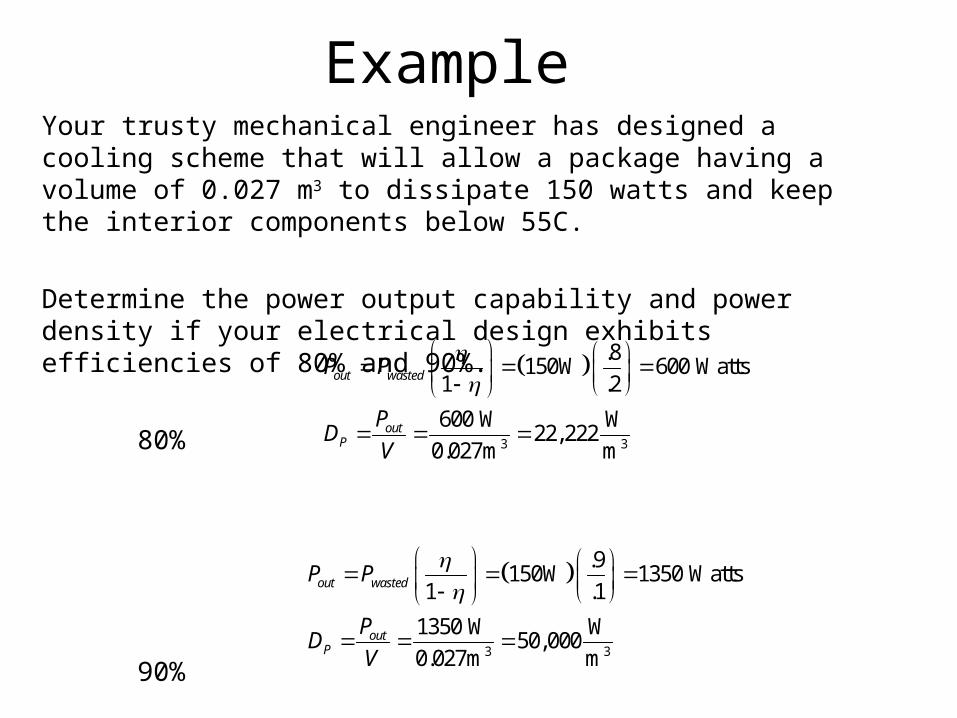
ExampleYour trusty mechanical engineer has designed a cooling scheme that will allow a package having a volume of 0.027 m3 to dissipate 150 watts and keep the interior components below 55C.
Determine the power output capability and power density if your electrical design exhibits efficiencies of 80% and 90%.
80%
90%
3 3
.8150W 600 Watts
1 .2
600 W W22,222
0.027m m
out wasted
outP
P P
PD
V
3 3
.9150W 1350 Watts
1 .1
1350 W W50,000
0.027m m
out wasted
outP
P P
PD
V