power steering box fit the steering wheel … · 16. refit the tie bar to the steering box, and...
TRANSCRIPT

POWER STEERING BOX
Remove and refit
Service tools:Drop arm extractor-MS252A
NOTE: It is important that whenever any part ofthe system, including the f lexible piping, isremoved or disconnected, that the utmostcleanliness is observed.
A l l p o r t s a n d h o s e c o n n e c t i o n s s h o u l d b esuitably sealed off to prevent ingress of dirt, etc.If metallic sediment is found in any part of thesystem, the complete system should be checked,the cause rect i f ied and the system thoroughlycleaned.
Under no circumstances must the engine bestarted until the reservoir has been filled. Failureto observe this rule will result in damage to the
pump.
Metr ic pipe f i t t ings are used with ‘0’ ring pipeends on the fittings to the steering box.
Fol low normal ‘0’ r ing replacement procedure
; . : ;:. whenever pipes are disconnected.. . .
Ensure that compatible metr ic components areused when fitting replacement pipes.
CAUTION: PRIOR TO REMOVING ANY OF THECOMPONENTS I N C O R P O R A T E D I N THESTEERING LINKAGE, IT IS IMPERATIVE THAT THER O A D W H E E L S A R E I N A S T R A I G H T A H E A DPOSITION AND THAT THE STEERING WHEEL IST H E N R E M O V E D T O P R E V E N T T H E C R U I S ECONTROL SPIRAL CASSETTE BEING WOUND UPOR DAMAGED IF THE STEERING LINKAGE ISINADVERTENTLY MOVED OR ROTATED.AFTER REFllTlNG STEERING LINKAGECOMPONENTS, THE ROAD WHEELS MUST BERE-POSITIONED S T R A I G H T A H E A D BEFOREFllTlNG T H E S T E E R I N G W H E E L , D O N O TRECONNECT THE MULTI-PLUG TO THE CASSETTEOR FIT THE TRIM PAD AT THIS STAGE. IF, AFTERTHE VEHICLE HAS BEEN DRIVEN, IT IS FOUNDT H A T THE STEERING WHEEL REQUIRESRE-POSITIONING, REMOVE THE WHEEL.RE-ALIGN THE DRIVE PEGS ON THE CRUISEC O N T R O L CASSElTE B Y S L I G H T L Y R O T A T I N GT H E U P P E R P A R T O F T H E CASSE’ITE I N T H EAPPROPRIATE DIRECTION UNTIL THE PEGS LIEHORIZONTAL TO THE STEERING COLUMN.
FIT THE STEERING WHEEL ENSURING THAT THEDRIVE PEGS LOCATE IN THEIR RESPECTIVEHOLES ON THE REAR OF THE STEERING WHEEL.
A F T E R F I N A L A L I G N M E N T R E C O N N E C T T H EMULTI-PLUG TO THE CASSETTE, TIGHTEN THESTEERING WHEEL SECURING NUT AND FIT THETRIM PAD.
Removing
1 .2 .3 .
4 .
5 .
Park the vehicle on a level surface.Prop open the hood.Remove the filler cap from the power steeringfluid reservoir.Disconnect the f luid pipes from the pump.Drain and discard the fluid. Replace the fillercap.Disconnect the f luid feed and return pipesfrom the steering box.
6. Seal all disconnected hose connections toprevent ingress of foreign matter.
7 lack up and support the chassis front end withaxle stands. Alternatively, raise the vehicle on ahoist.
WARNING: Whichever method is adopted, i t isessent ia l that the wheels are chocked, theparking brake is applied, and low range selectedwith differential lock engaged.
Continued-’

,ga, r(HI*uC
ROVER
8 .
9 .
10.
11.
1 2 .
1 3 .
1 4 .
Disconnect the drag fink from the drop armusing a suitable extractor.Remove the drop arm, using drop armextractor MS252A.Remove the pinch bolt attaching the universaljoint to the power steering box.Loosen the nut securing the tie bar to thechassis.Remove the bolts securing the tie bar to thesteering box and move the tie bar aside.Remove the f ixings attaching the powersteering box to the chassrs side member.Withdraw the power steering box.
8,19
RR2196E
Refitt ing
9;18
15. Refit the steering box to the chassis sidemember and t ighten the four Nyloc nuts tothe correct torque (see section 06-Torquevalues).
16. Refi t the t ie bar to the steering box, andtighten the tie bar securing nut to the correcttorque (see section 06-Torque values).
17. Reconnect the pinch bolt, attaching theuniversal joint to the power steering box, andtighten to the correct torque (see sectionOC-Torque values).
18. Refit the drop arm.19. Refit the drag link and secure.20. Lower the vehicle to ground level.21. Remove the sealing. plugs and reconnect the
flexible hoses to the steering box.
2 2 .
2 3 .
2 5 .2 6 .
2 7 .
Remove the sealing plug and refit the flexiblehose to the power steering pump.Ensure that the steering wheel is correctlyaligned when t h e w h e e l s a r e in thestraight-ahead position.
NOTE: II may be necessary to remove thesteering w h e e l a n d r e p o s i t i o n o n t h esplines t o o b t a i n t h i s c o n d i t i o n . S e esteering wheel- remove and refit.
Remove the filler cap from the power steeringfluid reservoir. Fill the reservoir to the oil levelmark on the dipstick attached to the filler capwith the recommended fluid (see Section 09)and bleed the power steering system. Seepower steering system-bleed.Check the liuid level and replace the filler cap.Check, and if necessary, adjust the steeringbox.Test the steering system for leaks. with theengine running, by holding the steering hardon full lock in both directions.
. \.,
CAUTION: Do not maintain this pressure formore than 30 seconds in any one minute, toavoid causing the oil to overheat and possibledamage to the seals.
28. Close the hood.29. Road test the vehicle.
2
;.

. ..
POWER STEERING BOX OVERHAUL
Service tools:LSTl20 -‘C’ WrenchLSTl l9 -Worm adjust ing wrenchMS252A -Drop arm extractor606602 -Ring expander606603 -Ring compressor606604 -Seal saver, sector shaftR01015 -Seal saver, valve and wormR01016 -Torque setting tool
Dismantle
I. Remove the steering box from the vehicle,and withdraw the drop arm.
; . , . :‘,.
:.. .:,Rotate the retainer ring, as necessary, until oneend is approximately 12 mm (0.500 in) fromthe extractor hole.Lift the cover retaining ring from the groove inthe cylinder bore, using a suitable pointed driftapplied through the hole provided in thecylinder wall.Complete the removal of the retainer r ing,using a screwdriver.Turn on left lock until the piston pushes outthe end cover.
6 .
7 .8 .9 .
1 0 .
1 1 .
Loosen the set screw retaining the rack padadjuster.Remove the rack pad adjuster.Remove the sector shaft adjuster locknut.Remove the sector shaft cover fixings.Screw in the sector shaft adjuster unti l thecover is removed.Slide out the sector shaft.
12. Withdraw the piston. using a suitable boltscrewed Into the tapped hole in the piston.
Continued
_’
,.:.
REVISED: DEC. 87 3 .’.:.

‘.‘.,
:.
‘.‘;;
:
.:
..I
...
‘.....
RANGt“*’ R O V E R
.
13. R e m o v e the worm adjuster locknut using ‘C’Wrench, LSTI 20.
14. Remove the worm adjuster using wrenchLSTll9.
IS.
16.
17.18.
19.
Tap the splined end of the shaft to free thebearing.Withdraw the bearing cup and caged bal lbearing assembly.Withdraw the valve and worm assembly.Withdraw the inner bearing ball race andshims.Retain the shims for reassembly
Steering box seals
20. Remove the circlip and seals from the sectorshaft housing bore.
NOTE: Do not remove the sector bushesfrom the casing, Replacement parts are notavailable.
I
21. Remove the circlip and seals from the inputshaft housing bore.
..-
‘. 1
RR234SE
Inspecting
22. Discard all rubber seals and provide
replacements.
NOTE: A rubber seal is fitted behind theplastic ring on the rack piston. Discard theseal and also the plastic ring and providereplacements.
lj. .’
4 REVISED: DEC. 87
AR23!5OE fs ’
‘ ‘. ‘.-
.i :
! *
.’ .
:

STEERING 157 1
‘.
,_-
; ,:
(.’
. :Steering box casing
23. Examine the piston bore for traces of scoringand wear .
24. Examine the inlet tube thread for damage. Ifrepair is necessary this can be undertaken byusing a suitable tap.
25. Examine the feed tube for signs of cracking.
23
Sector shaft assembly
26. Check that there is no side play on the rollers.27. If excessive side play on the roller does exist
fit a new sector shaft.28. Check the condition of the adjuster screw
threads.29. Examine the bearing areas on the shaft for
excessive wear.30 . Examine the gear teeth fo r uneven o r
excessive wear.
Sector shaft cover assembly
31. The cover, bush and seat are supplied as acomplete assembly for replacement purposes.
Sector shaft adjuster locknut
32. The locknut functions also as a fluid seal, anew nut be fitted at overhaul.
Valve and worm assembly
33. Examine the valve rings which must be freefrom cuts, scratches and grooves. The valverings should be a loose fit in the valvegrooves.
34. Remove the damaged rings ensuring that nodamage is done to the seal grooves.
35. If required, fit replacement rings, using thering expander 606602. Warm the rings andexpander tool to aid assembly, using hot waterfor this purpose. Fit the rings to the expander,slide the expander over the valve and wormassembly, in turn fit the rings to theirrespective grooves. Remove the expander,slide the valve and worm assembly into thering compressor 606603 and allow the rings to
NOTE: The expander will not pass over ringsalready fitted. The rings must be discardedto allow access and then new rings must befitted.
Continued * ’
REVISED: DEC. 87 5

I
:.,
;,a
*
:
‘.
:‘. .‘,
l-l57 STEERING.\, .# .VL
“*’ R O V E R
36. Examine the bearing areas for wear. The areasmust be smooth and not indented.
37. Examine the worm track which must besmooth and not indented.
38. Check for wear on the torsion bar assemblypins; no free movement should exist betweenthe input shaft and the worm.
NOTE: Any sign of wear makes it essentialtha t a new va lve and worm assembly isfitted.
RR932M
Ball bearing and cage assemblies
39. Examine the ball races and cups for wear andgeneral condition.
40. If the ball cage has worn against the bearingcup, fit replacements.
41. Bearing balls must be retained by the cage.42. Bearings and cage repair are carried out by the
complete replacement of the bearings andcage assembly.
6 REVISED: DEC. 87
43. To remove the inner bearing cup and shimwashers, jar the steering box on the workbench, or use a suitable extractor.
i “I
NOTE: Should dif f iculty be experienced atthis stage, warm the casing and the bearingassembly. Cool the bearing cup using asuitable mandrel and jar the steer ing boxon the bench.
Rack thrust pad and adjuster
44. Examine the thrust pad for scores.45. Examine the adfuster for wear in the pad seat.46. Examine the nylon pad for distort ion and
adjuster set screw assembly for wear.
46/ ‘P
Rack and piston
47.48.
49.
5 0 .
Examine for excessive wear on the rack teeth.Ensure the thrust pad bearing surface is freefrom scores and wear.Ensure that the piston outer diameters are freefrom burrs and damage.Examine the seal and ring groove for scoresand damage.

51. Fit a new rubber ring to the piston. Warm the Sector shaft sealwhite nylon seal and fit this to the piston.
52. Sl ide the piston assembly into the cylinderwith the rack tube outwards. Allow to cool.
Reassemble
NOTE: When fitting replacement oil seals, thesemust be lubricated with recommended fluid.Also ensure that absolute cleanliness is observedduring assembly.
Input shaft oil seal
53. Fit the seal, lipped side first, into the housing.When correctly seated, the seal backing will lieflat on the bore shoulder.
54. Fit the extrusion washer and secure with thecirclip.
,53
RR2362E x’ I
55. Fit the oil seal, lipped side first.56. Fit the extrusion washer.57. Fit the dust seal, lipped side last.58. Fit the circlip.
RRQ38M
Fitting the valve and worm assembly
59 . If removed, refi t the original shim washer(s)and the inner bearing cap. Only PetroleumJelly may be used as an aid to assembling thebearings.
NOTE: If the original shims are notavailable, fit shim(s) of 0.76 mm (0.030 in)nominal thickness.
Continued
REVISED: DEC. 87 7.

1987 RANGEROVER
60. Fit the inner cage and bearings assembly.61. Fit the valve and worm assembly, using seal
saver RQ1015 to protect the input shaft seal.62. Fit the outer cage and bearings assembly.63. Fit the outer bearing cup.
63
64. F i t a new worm adjuster seal ing r ing andloosely screw the adjuster into the casing. Fitthe locknut, but do not tighten.
65. Turn in the worm adjuster until the end-floatat the input is almost eliminated.
66. Measure and record the maximum rol l ingdistance of the valve and worm assembly,using a spring balance and cord coiled aroundthe torque setting tool ~01016.
67. Turn in the worm adjuster to increase thefigure recorded in instruction 66 by 1.8 to 2.2kg (4 to 5 lb) at 1.250 in (31.7 mm) radius tosettle the bearings, then back off the wormadjuster until the figure recorded in instruction66 is increased by 0.9 to 1.3 kg (2 to 3 lb)only, with locknut tight. Use worm adjustingwrench LSTl19 and ‘C’ wrench LSTI 20.
Fitting the rack and piston
68.
6 9 .
7 0 .
Screw a slave bolt into the piston head for useas an assembly tool.Fit the piston and rack assembly so that thepiston is 63.5 mm (2.5 in) approximately fromthe outer end of the bore.Feed in the sector shaft using seal saver606604 aligning the centre gear pitch on therack with the centre gear tooth on the sectorshaft . Push in the sector shaft , and, at thesame time rotate the input shaft about a smallarc to allow the sector roller to engage theworm.
RRS41H
a REVISED: DEC. 87

7 4 .7 5 .
7 6 .7 7 .
Fitting the rack adjuster
71. Fit the sealing ring to the rack adjuster.72. Fit the rack adjuster and thrust pad to engage
the rack. Back off a half turn on the adjuster.73. Loosely fit the nylon pad and adjuster set
screw assembly to engage the rack adjuster.
NOTE: Before tightening the fixings, rotatethe input shaft about a small arc to ensurethat the sector roller is free to move in thevalve worm.
78. Fit the cover fixings and tighten to the correcttorque (see section 06-Torque values).
Fitting the cylinder cover
79. Fit the square section seal to the cover.80. Remove the slave bolt fitted at operation 68
and press the cover into the cylinder justsufficient to clear the retainer ring groove.
81. Fit the retainer ring to the groove with oneend of the ring positioned I2 mm (0.5 in)approximately from the extractor hole.
RR942M
Fitting the sector shaft cover
Fit the sealing ring to the cover.Screw the cover assembly fully on to thesector shaft adjuster screw.Position the cover on to the casing.Tap the cover in place. It necessary back offon the sector shaft adjuster screw to allow thecover to joint fully with the casing. RR944M I I I
Continued
9 .i:,;.

RANGElg8’ ROVER
. . . .. .
I
Adjusting the sector shaft Torque peak check
82.
83.
84.
as.
86.
87.
,
Set the worm on centre by rotating the inputshaft half the total number of turns from eitherlock.Rotate the sector shaf t ad jus t ing screwcounter-clockwise to obtain backlash betweenthe input shaft and the sector shaft.Rotate the sector shaf t ad jus t ing screwclockwise until the backlash is just eliminated.Measure and record the max imum ro l l ingresistance at the input shaft, using a springbalance, cord and torque tool ROlOl6.Ho ld the sector shat t ad jus ter sc rew andloosely tit a new locknut.Turn in the sector shaft adjuster screw untilthe f igure recorded in ins t ruct ion 85 i sincreased by 0.9 to 1.3 kg (2 to 3 lb) with thelocknut tightened.
Adjusting the rack adjuster
aa. Turn in the rack adjuster to increase the figurerecorded in instruction 87 by 0.9 to 1.3 kg (2to 3 lb). The final figure may be less than7.25 kg (16 lb) but must not exceed thisfigure.
89. Lock the rack adjuster in position with the setscrew.
With the input shaft rotated from lock-to-lock, the .‘.. ’ ”roliing resisiance torque figures should be greatestacross the centre position (1.5 turns approximatelyfrom full lock) and equally disposed about thecentre position.
The condition depends on the value of shimmingfitted between the valve and worm assembly innerbear ing cup and the cas ing. The or ig inal sh imwasher value will give the correct torque peakpos i t ion un less major components have beenrep laced.
Procedure
90. Wi th the input coupl ing shaf t toward theoperator, turn the shaft fully -‘>counter-clockwise.
91. Check the torque f igures obta ined f romlock-to-lock using a spring balance cord andtorque tool R01016.
Y‘5
‘. ., ,:
Adjustments
92. Note where the greatest figures are recordedrelative to the steering position. If the greatestfigures are not recorded across the centre oftravel (i.e. steering straight-ahead position),adjust as follows:
.,,:. .‘.

: If the torque peak occurs before the centreposition, add to the shim washer value; if thetorque peak occurs after the centre position,subtract from the shim washer value.
Shim washers are available as follows:O.O3mm, O.O7mm, 0.12mm and 0.24mm (0.0015 in,0.003 in, 0.005 in and 0.010 in).
NOTE: Adjustment of 0.07mm (0.003 in) to theshim value will move the torque peak area by l/4turn approximately on the shaft.
9 3 .
9 4 .9 5 .
9 6 .
Fit the drop arm to the steering box using anew tab washer. Tighten the nut to the correctt o r q u e ( s e e s e c t i o n OC-Torque values)andbend over tab.Refit the steering box to the vehicle.Replenish the system with the correct grade offluid. Refer to Recommended Lubricants andPower Steering System-bleed.Test the system for leaks, with the enginerunning, by holding the steering hard on fulllock in both directions.
NOTE: Do not maintain this pressure formore than 30 seconds in any one minute toavoid overheating the fluid and possiblydamaging the seals.
9 7 . Road test the vehicle.
POWER STEERING SYSTEM
Bleed
1. Fill the steering fluid reservoir to theappropriate level marking on the dipstick withone of the recommended fluids.
2. Start and run the engine until it attains normaloperating temperature.
3. Check and correct the reservoir fluid level.
NOTE: During the carrying out of items 4, 5and 6, ensure that the steering reservoir iskept full. Do not increase the engine speedor move the steering wheel.
4. Run the engine at idle speed, loosen thebleed screw. When fluid seepage past thebleed screw is observed, retighten the screw.
Ensure that the fluid level is in alignment withthe mark on the dipstick.Wipe off all fluid lost during bleeding.Check all hose connections, pump andsteering box for fluid leaks under pressure byholding the steering hard on full lock in bothdirections.
CAUTION: Do not maintain this pressure formore than 30 seconds in any one minute, toavoid causing the oil to overheat andpossible damage to the seals. The steeringshould be smooth. lock-to-lock in bothdirections, that is, no heavy or light spotswhen changing direction when the vehicleis stationary.
(-any o u t a s h o r t r o a d t e s t . I f necessary,repeat the complete foregoing procedure.
11

POWER STEERING SYSTEM Procedure
.,. I Test 1 .
If there is a lack of power assistance for thesteering the pressure of the hydraulic pump shouldbe checked first before fitting new components tothe system. The fault diagnosis chart should also beused to assist in tracing faults in the power steeringsystem. 2 .
SERVICE TOOLS
HY23 -Pressure gaugejD10-2 -Test adaptorLSTlO-11 -Thread adaptor
3 .
4 .
9 .
,. . Y .
L-JA‘14ERR10
A. Steering box.B. Steering pump.C. Existing hose, steering box to pump.D. Hose JDIO-3A.E. Test adaptor JDIO-2.F. Pressure gauge HY23.G. Thread adaptor LSTIO-11.H. Thread adaptor LSTl O-l I.
.
: , ’ ‘,.,.;..’
1 2
RANGElg8’ ROVER
The hydraulic pressure gauge in conjunctionwith the test adaptor is used for testing thepower steering system. This gauge is calibratedto read up to 140 kgflcm’ (2000 p.s.i.) and thenormal pressure which may be expected in thepower steering system is 77 kgf lcm’ (1100p.s.i.).Under certain fault conditions of the hydraulicpump it is possible to obtain pressures up to105 kgf/cm’ ( 1 5 0 0 p.s.i.). T h e r e f o r e , i t i simportant IO realise that the pressure upon thegauge is in direct proportion to the pressurebeing exerted upon the steering wheel. Whentesting, apply pressure to the steering wheelvery gradually while carefully observing thepressure gauge.Check, and if necessary replenish, the fluidreservoir.E x a m i n e t h e p o w e r s t e e r i n g u n i t s a n dconnections for leaks. All leaks must berectified before attempting to test the system.Check the steering pump drive belt forcondition and tension, rectify as necessar)‘.Assemble the test equipment and f i t to thevehicle, as shown in the diagram.Open the tap in the adaptor.Bleed the system but exercise extreme carewhen carrying out this operation so as not tooverload the pressure gauge.With the system in good condition, thepressures should be as follows:
(a) Steering wheel held hard on full lock andengine running at 1,000 rev/min, thepressure should be 70 to 77 kgflcm’ (1000to 1100 p.s.i.). I’*
(b) With the engine idl ing and the steering iwheel held hard on full lock, the pressureshould be 28 kgflcm’ (400 p.s.i.) minimum.
‘I
.’

These checks should be carried out first on onelock, then on the other.
CAUTION: Under no circumstances must thesteer ing wheel be held on ful l lock for morethan 30 seconds in any one minute, otherwisethere will be a tendency for the oil to overheatand possible damage to the seals may result.
10.
11.
12.
13.
Release the steering wheel and allow theengine to idle. The pressure should be below7 kgf/cm’ (100 p.s.i.1.If the pressures recorded during the foregoingtests are outside the specified range, orpressure imbalance is recorded, a fault exist inthe system. To determine if the fault is in thesteering box or the pump, close the adaptortap for a period not exceeding five seconds.If the gauge fails to register the specifiedpressure, the pump is at fault and a new unitmust be fitted.Repeat the foregoing test after fitting a newpump and bleeding the system. I f pumpdelivery is satisfactory but low pressure or asubstantial imbalance exists, the fault must bein the steering box valve and worm assembly.
ADJUST POWER STEERING BOX
NOTE: The condit ion of adjustment which mustbe checked is one of minimum backlash withoutovert ightness when the wheels are in thestraight-ahead position.
1. Jack up the front of the vehicle unti l thewheels are clear of the ground and supportthe chassis with axle stands.
WARNING: I t is essent ia l that the wheels arechocked, the parking brake appl ied, and lowrange selected with differential lock engaged.
2.
3.
Gently rock the steering wheel about thestraight-ahead position to obtain the ‘feel’ ofthe backlash present. This backlash must notbe more than 9.5mm (0.375 in).Continue the rocking action while an assistantslowly tightens the steering box adjuster screwafter loosening the locknut until the steeringwheel movement is reduced to 9.5mm (0.375in) maximum.
4. Tighten the locknut,. then turn the steeringwheel from lock to lock and check that noexcessive tightness exists at any point.
5. Lower the vehicle to ground level and removethe wheel chocks.
6. Road test the vehicle. .:
.:) RANtiE. < : lg8’ ROVER
“I .,: . . . _
j:;:i.*
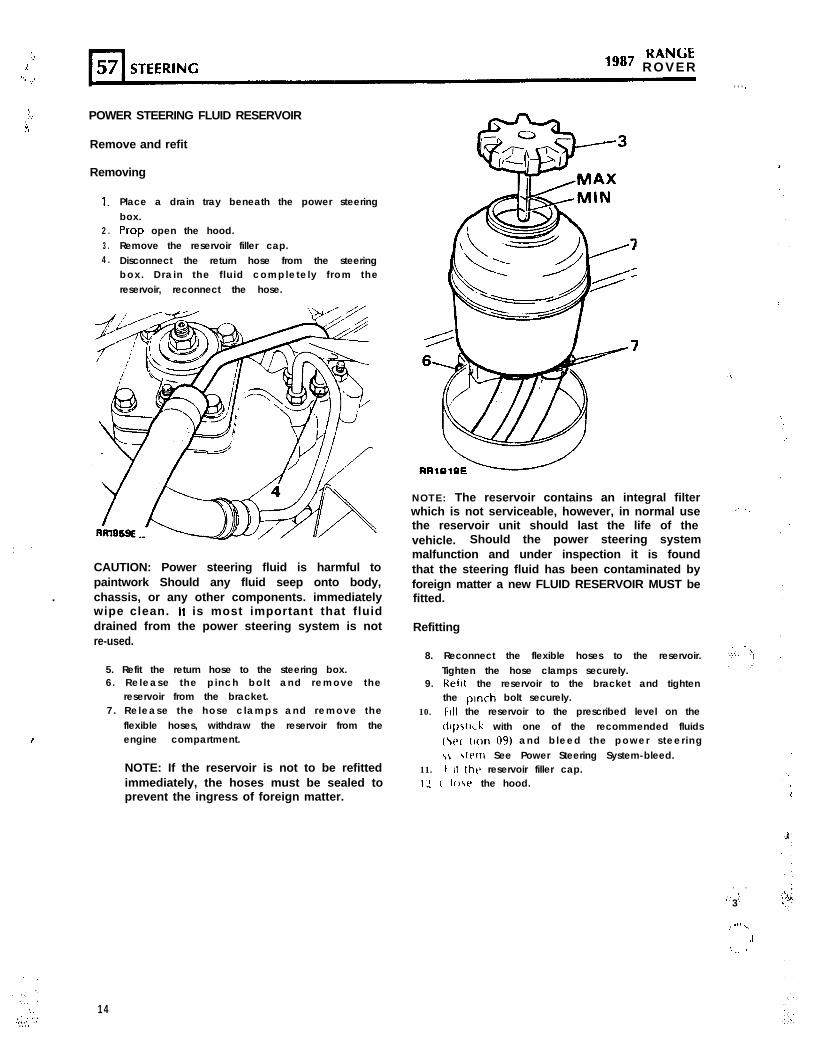
POWER STEERING FLUID RESERVOIR
Remove and refit
Removing
1.
2 .3 .4 .
Place a drain tray beneath the power steeringbox.Prop open the hood.Remove the reservoir filler cap.Disconnect the return hose from the steeringbox. Drain the f luid completely from thereservoir, reconnect the hose.
CAUTION: Power steering fluid is harmful topaintwork Should any fluid seep onto body,
. chassis, or any other components. immediatelywipe clean. It is most important that fluiddrained from the power steering system is notre-used.
I
5. Refit the return hose to the steering box.6. Release the pinch bolt and remove the
reservoir from the bracket.7. Release the hose clamps and remove the
flexible hoses, withdraw the reservoir from theengine compartment.
NOTE: If the reservoir is not to be refittedimmediately, the hoses must be sealed toprevent the ingress of foreign matter.
‘:,
NOTE: The reservoir contains an integral filterwhich is not serviceable, however, in normal usethe reservoir unit should last the life of thevehicle. Should the power steering systemmalfunction and under inspection it is foundthat the steering fluid has been contaminated byforeign matter a new FLUID RESERVOIR MUST befitted.
Refitting
8. Reconnect the flexible hoses to the reservoir.Tighten the hose clamps securely.
9. Relit the reservoir to the bracket and tightenthe pinch bolt securely.
10. Ftll the reservoir to the prescribed level on the~I~SIIC~ with one of the recommended fluids(\ts( tlon 09) and bleed the power steering,L \ttlrn See Power Steering System-bleed.
11. t II Ihe reservoir filler cap.12 C Io\e the hood.
. . . .*- : ;3
, _ .‘. .,
.j
‘.__ ’
‘.‘.
.,,I : ‘.‘.’.:::,
1 4

POWER STEERING PUMP DRIVE BELT
Adjust
Procedure
1 .
2 .
3 .
4 .
5.
Prop open the hood and disconnect thebattery negative lead.Check, by thumb pressure, the belt tensionbetween the crankshaft and the pump pulley.There should be a free movement of between4 to 6mm (0.19 to 0.25 in).Loosen the two nuts at the side of the pumpto allow the pump to be pivoted.Loosen the bolt securing the pump lowerbracket to the slotted adjustment link.Pivot the pump (in the direction of the boldarrow) as necessary and adjust until the correctbelt tension is obtained.
CAUTION: Do not use the pump casing as apoint of leverage when tensioning the powersteering drive belt. Damage to the pump casingmay be caused leading to fluid leakage.
6. Maintaining the tension, tighten the pumpadjusting bolt and the top pivot nuts.
NOTE: Check the alternator drive belttension after adjusting the power steeringpump belt.
7. Reconnect the battery negative lead and closethe hood.
NOTE: Check adjustment after runningengine at fast idle speed for 3 to 5 minutesif a new belt has been fitted.
POWER STEERING PUMP DRIVE BELT
Remove and refit
Removing or preparing for the fitting of a new .belt.
1 .
2 .
3 .
4 .5.
Prop open the hood and disconnect thebattery negative lead.Loosen the idler pulley bolt and remove thefan belt.Loosen the alternator mountings and removethe drive belt.Loosen the power steering pump mountings.Pivot the pump and remove the drive belt.
Refitting
6. Locate the driving belt over the crankshaft andpump pulleys.
7. Adjust the position of the pump to give adriving belt tension of 4 to 6mm (0.19 to 0.25in) movement when checked by thumbpressure midway between the crankshaft andpump pulleys.
CAUTION: Do not use the pump casing as apoint of leverage when- tensioning the powersteering drive belt. Damage to the pump casingmay be caused leading to fluid leakage.
8. Maintaining the tension, tighten the pumpadjusting bolt and the top pivot nut.
9. Refit the fan belt and ad/ust the tension togive 4 to 6mm (0.19 to 0.25 in) movementwhen checked by thumb pressure midwaybetween the crankshaft and water pumppulleys.
REVISED: MAY 89
Continued
1 5

r-l57 STEERING1987 KANbt
ROVERc I
1 0 .
1 1 .
Refit the alternator drive belt and adjust togive 4 to 6mm (0.19 to 0.25 in) movementwhen checked midway between the powersteering pump and alternator pulleys.Reconnect the battery negative lead and closethe hood.
NOTE: Check adjustment after runningengine at fast idle speed for 3 to 5 minutesif a new belt has been fitted.
STEERING PUMP
NOTE: The power steering pump is not aserviceable item. In the event of failure ordamage a new pump must be fitted.
Remove and refit
) i Removing
1.
2 .
3 ..,, .
4 .
5 .
6 .
7 .
8 .
Disconnect the battery negative lead.Loosen the alternator pivot bolts andadjustment link bolts, pivot the alternatorinwards and remove the drive belt.Loosen the water pump drive belt idler pulleyand remove the drive belt.Remove the left hand bank spark plug leadsand detach the distributor cap, place the leadsand cap to one side.Disconnect the electrical plug from thedistributor amplifier unit.Loosen the two nuts securing the powersteering pump pivot bracket.Release the three bolts securing the pulley tothe steering pump, do not remove them atthis stage.Release the bottom adjustment bolt below thesteering pump and pivot the pump inwardstowards the water pump to enable the drivebelt to be removed.
6
9. Remove the three bolts with plain washersretaining the pulley to the pump and withdrawthe pulley.
NOTE: Place a drain tray underneath thevehicle to catch any power steering fluidwhich will seep from the pump when thefluid pipe is disconnected.
CAUTION: Power steering fluid is harmful topaintwork. Should any fluid seep onto the body, -. ‘-‘<,chassis, or any other components immediately -wipe clean. lt is most important that fluiddrained from the power steering system is notre-used.
10. Disconnect the fluid pipe from the side of thepump, plug the pipe and pump openings toprevent ingress of dirt.
REVISED: MAY 89I :

ro;;; 1987 STEERING 57
11.
12.
Remove the three bolts securing the pump tothe pivot bracket, maneuver the pump out ofthe bracket and withdraw it from the enginecompartment as far as the remainingconnected fluid hose will permit.Release the clamp securing the hose to the
Pump, remove the hose and plug bothopenings to prevent ingress of dirt.
Refitt ing
13. Remove the plug from the fluid hose andsecure the hose to a NEW pump. Tighten thehose clamp securely.
14. Maneuver the pump into the pivot bracket andsecure in position with the three retainingbolts. Tighten the bolts to the specified torque(see section 06-Torque values).
15. Remove the plugs f rom the f luid pipe andsteering pump openings and f i t the pipe.Tighten the pipe securely.
CAUTION: Care should be taken to ensure thatthe high pressure fluid pipe is well clear of boththe drive belt and the top of the power steeringbox.
16.
17.
18.
Fit the pulley to the steering pump driveflange, coat the three bolts with Loctite and fitto the steering pump, do not-fully tighten thebolts at this stage.Refit the crankshaft to steering pump drivebelt, pivot the steering pump outwards totension the belt, t ighten the pivot boltss e c u r e l y . C h e c k t h a t t h e b e l t d e f l e c t sapproximately 4 to 6 mm (0 .19 to 0.25in)when checked by thumb pressure midwaybetween the crankshaft and pump pulleys.Tighten the three steering pump pulleyretaining bolts to the specified torque (seesection 06-Torque values).Reverse the remaining removal instructions.Bleed the power steering system.Test the power steering system for leaks withthe engine running, holding the steering onfull lock in both directions.
CAUTION: Do not maintain this pressure formore than 30 seconds in any one minute, toavoid causing the oil to overheat and possibledamage to the seals.
22. Close the hood.23. Road test the vehicle.

1987 KANbtROVER
POWER STEERING
FAULT DIAGNOSIS
SYMPTOM CAUSE TEST ACTION CURE
INSUFFICIENT POWER (I ) Lack of fluid Check hydraulic fluid If low, fill and bleed the
GSISTANCE WHEN tank level system
PARKING
(2) Driving belt Check belt tension Adjust the driving belt
(3) Defective hydraulic
pump
(a) Fit pressure guage of pressure is outsidebetween high limits (high or low) afterpressure hose and checking items I and 2,steering pump with see Note 2steering held hard onfull lock, see Note 1and ‘Power SteeringSystem Test’
(b) Release steeringwheel and allowengine to idle. See‘Power SteeringSystem Test’
If pressure is greater,check box for freedomand self- centering action
POOR HANDLINGWHEN VEHICLE IS INMOTION
Lack of castor action This is caused by It is most important that
(wheels will not return to over-tightening the this screw is correctly
centre) rocker shaft backlash adjusted. Seeadjusting screw on top instructions governingof the steering box adjustment
HYDRAULIC FLUIDLEAKS
Damaged pipework, Check by visual Tighten or renew asloose connecting unions inspection; leaks from necessary
etc. the high pressure Irnesare best found whileholding the steering onfull lock with enginerunning at fast idle speed(See Note 1)
NOTE: Leaks from the steering box tend to show Check ‘0’ rings on Renew as necessaryup under low pressure conditions, that is, engine pipeworkidling and no pressure on steering wheel
Continued
1 8

S T E E R I N G 57r l
S Y M P T O M CAUSE TEST ACTION CURE
EXCESSIVE NOISE (1) If the high pressure Check the loose runs of Alter hose route orhose is allowed to the hoses insulate as necessarycome into contactwith the body shell,or any componentnot insulated by thebody mounting,noise will betransmitted to thecar interior
(2) Noise from hydraulic Check oil level and bleed If no cure, change
pump system hydraulic pump
Note I. Never hold the steering wheel on full lock for more than 30 seconds in any one minute, to avoidcausing the oil to overheat and possible damage to the seals.
Note 2. High pressure-
Low pressure-
In general it may be assumed that excessive pressure is due to a fault in thehydraulic pump.Insufficient pressure may be caused by one of the following:
1. Low fluid level in reservoir ) Most usual cause of2. Pump belt slip ) insufficient pressure
3. Leaks in the power steering system4. Hydraulic pump not delivering correct pressure5. Fault in steering box valve and worm assembly6. Leak at piston sealing in steering box7. Worn components in either steering box or hydraulic pump
Steering pump
Make/type ......................................................................... Hobourn-Eaton series 200
Operating pressure - straight ahead position - at idle ...... 7 kgf/cm’ (100 p.s.i.1 maximumFull lock (left or right) at idle ............................................ 28 kgf/cm’ (400 p.s.i.) minimumFull lock (left or right) 1000 rev/min ................................. 70-77 kgflcm’ (1000-1100 p.s.i.)
.i
‘9 .::.

,987 KANCitROVER
COUPLING SHAFT AND UNIVERSAL JOINTS
Remove and refit
CAUTION: PRIOR TO REMOVING ANY OF THECOMPONENTS INCORPORATED IN THESTEERING LINKAGE, IT IS IMPERATIVE THAT THEROAD WHEELS ARE IN A STRAIGHT AHEADPOSITION AND THAT THE STEERING WHEEL ISTHEN REMOVED TO PREVENT THE CRUISECONTROL SPIRAL CASSETTE BEING WOUND UPOR DAMAGED IF THE STEERING LINKAGE ISINADVERTENTLY MOVED OR ROTATED.
AFTER REFITTING STEERING LINKAGECOMPONENTS, THE ROAD WHEELS MUST BERE-POSITIONED STRAIGHT AHEAD BEFOREFll-FlNC THE STEERING WHEEL, DO NOTRECONNECT THE MULTI-PLUG TO THE CASSETTEOR FIT THE TRIM PAD AT THIS STAGE. IF, AFTERTHE VEHICLE HAS BEEN DRIVEN, IT IS FOUNDTHAT THE STEERING WHEEL REQUIRESRE-POSITIONING, REMOVE THE WHEEL.RE-ALIGN THE DRIVE PEGS ON THE CRUISECONTROL CASSETTE BY SLIGHTLY ROTATINGTHE UPPER PART OF THE CASSETTE IN THEAPPROPRIATE DIRECTION UNTIL THE PEGS LIEHORIZONTAL TO THE STEERING COLUMN.
FIT THE STEERING WHEEL ENSURING THAT THEDRIVE PEGS LOCATE IN THEIR RESPECTIVEHOLES ON THE REAR OF THE STEERING WHEEL.
AFFER FINAL ALIGNMENT RE-CONNECI-MULTI-PLUG TO THE CASSETTE, TIGHTENSTEERING WHEEL SECURING NUT AND FIT
‘TRIM PAD.
Removing
THETHETHE
1. Ensure the road wheels are in the straightahead position.
NOTE: To gain access to the coupling shaftit is necessary to remove the air flow sensorand air filter canister.
2. Remove one pinch bolt from the top universaljoint to the steering column.
3. Remove two pinch bolts from the loweruniversal joint.
4. Maneuver the coupling shaft top universaljoint up the steering column splines to releasethe lower joint from the steering box splines.Withdraw the shaft from the steering columnsplines.
5. Withdraw the lower universal joint from thecoupling shaft.
20
NOTE: Do not dismantle the upper couplingjoint. The steering shaft, rubber couplingand top universal joint is only available asan assembly.
6. Inspect both universal joints for wear andexcessive play, fit new joints if necessary.
7. Inspect the rubber coupling for condit ion -rubber deterioration, fit a new rubber couplingassembly if necessary.
Refitting
NOTE: When refitting the universal joints totheir respective components ensure that thepinch bolt holes line up with theirrespective grooves.
8. Position the lower universal joint on the shaft.9. Position the shaft assembly toward the end of
the steering column, maneuver the assemblyup the steering column splines until it ispossible to locate the lower universal jointonto the steering box splines. ,;
0. Locate the bolt holes in the universal jointswith their respective grooves in the steeringcolumn, coupling shaft and steering boxsplines.
I 1. Fit the pinch bolts, and tighten to the correcttorque (see section 06-Torque values).
_. I..
‘.I
‘1.~
:-:.:

.’
STEERING WHEEL
Remove and refit
CAUTION: PRIOR TO REMOVING ANY OF THECOMPONENTS INCORPORATED IN THESTEERING LINKAGE, IT IS IMPERATIVE THAT THEROAD WHEELS ARE IN A STRAIGHT AHEADPOSITION AND THAT THE STEERING WHEEL ISTHEN REMOVED TO PREVENT THE CRUISECONTROL SPIRAL CASSETTE BEING WOUND UPOR DAMAGED IF THE STEERING LINKAGE ISINADVERTENTLY MOVED OR ROTATED.
AFTER REFllTlNG STEERING LINKAGECOMPONENTS, THE ROAD WHEELS MUST BERE-POSITIONED STRAIGHT AHEAD BEFOREFllTlNG THE STEERING WHEEL! DO NOTRECONNECT THE MULTI-PLUG TO THE CASSElTEQR FIT THE TRIM PAD AT THIS STAGE. IF, AFTERTHE VEHICLE HAS BEEN DRIVEN, IT IS FOUNDTHAT THE STEERING WHEEL REQUIRESRE-POSITIONING, REMOVE THE WHEEL.RE-ALIGN THE DRIVE PEGS ON THE CRUISECONTROL CASSETTE BY SLIGHTLY ROTATINGTHE UPPER PART OF THE CASSETTE IN THEAPPROPRIATE DIRECTION UNTIL THE PEGS LIEHORIZONTAL TO THE STEERING COLUMN.
,’
:.:‘. FIT THE STEERING WHEEL ENSURING THAT THE
DRIVE PhGS LOCATE IN THEIR RESPECTIVEHOLES ON THE REAR OF THE STEERING WHEEL.
AFTER FINAL ALIGNMENT RE-CONNECT THEMULTI-PLUG TO THE CASSElTE, TIGHTEN THESTEERING WHEEL SECURING NUT AND FIT THETRIM PAD.
Removing
Service Tools:1BG tot4 Steering wheel remover18G 1014-2 Adaptor pins
1 .2 .
, 3 .
. . .:”
NOTE: The steering column is of a ‘safety’type and incorporates shear pins. Thereforedo not impart shock loads to the steeringcolumn during removing and ref i t t ing thesteering wheel or at any time.
Disconnect the battery negative lead.Ensure the road wheels are in the straightahead position to enable the steering wheel tobe fitted in its correct location on re-assembly.Carefully ease the centre trim pad off thesteering wheel.
4 .
5 .
6 .
Disconnect the cru ise control electricalmulti-plug located in the small opening belowthe centre retaining nut.While holding the steering wheel remove theretaining nut and serrated washer.Extract the steering wheel using service tool18G 1014. Ensure the extractor pins areinserted in the threads up to shoulder of thepins.
CAUTION: IT IS IMPERATIVE THAT THE UPPERPART OF THE CRUISE CONTROL CASSElTE ISNOT ROTATED AFTER THE STEERING WHEEL ISREMOVED. TO PREVENT ROTATION SECURE THEUPPER AND LOWER PART OF THE CASSElTE INPOSITION WITH ADHESIVE TAPE.
Refitt ing
Ensure the road wheels are in the straightahead position.Place the steering wheel on the columnsplines and remove the previously appliedadhesive tape to the spiral cassette.Ensure the two drive pegs on the upper partof the cassette align with their respectivelocation holes on the underside of thesteering wheel, ease the wheel onto the pegs.
RR1@26E
Continued
- 21

KAN<;tlg8’ ROVER
CAUTION: Do not apply shock loads to thesteering wheel.
10. Fit the nut and washer and tighten to thespecified torque (see section 06-Torquevalues).
11. Reconnect the cruise control multi-plug andrefit the steering wheel centre cover.
12. Reconnect the battery.
STEERING COLUMN
NOTE: The steering column assembly is not aserviceable component.
Remove and refit
Service tool:18G1014-Extractor for steering wheel.1861014-2 Adaptor pins.
CAUTION: The steering column is of a ‘safety’type and incorporates shear pins. Therefore donot impart shock loads to the steering column atany time.
CAUTION: PRIOR TO REMOVING ANY OF THECOMPONENTS INCORPORATED IN THESTEERING LINKAGE, IT IS IMPERATIVE THAT THEROAD WHEELS ARE IN A STRAIGHT AHEADPOSITION AND THAT THE STEERING WHEEL ISTHEN REMOVED TO PREVENT THE CRUISECONTROL SPIRAL CASSETTE BEING WOUND UPOR DAMAGED IF THE STEERING LINKAGE ISINADVERTENTLY MOVED OR ROTATED.
AFTER REFITTING STEERING LINKAGECOMPONENTS, THE ROAD WHEELS MUST BERE-POSITIONED STRAIGHT AHEAD BEFOREFITTING THE STEERING WHEEL, DO NOTRECONNECT THE MULTI-PLUG TO THE CASSETTEOR FIT THE TRIM PAD AT THIS STAGE. IF, AFTERTHE VEHICLE HAS BEEN DRIVEN, IT IS FOUNDTHAT THE STEERING WHEEL REQUIRESRE-POSITIONING, REMOVE THE WHEEL.RE-ALIGN THE DRIVE PEGS ON THE CRUISECONTROL CASSETTE BY SLIGHTLY ROTATINGTHE UPPER PART OF THE CASSETTE IN THEAPPROPRIATE DIRECTION UNTIL THE PEGS LIEHORIZONTAL TO THE STEERING COLUMN.
FIT THE STEERING WHEEL ENSURING THAT THEDRIVE PEGS LOCATE IN THEIR RESPECTIVEHOLES ON THE REAR OF THE STEERING WHEEL.
22
AFTER FINAL ALIGNMENT RECONNECT THEMULTI-PLUG TO THE CASSETTE, TIGHTEN THE .STEERING WHEEL SECURING NUT AND FIT THE I : .:TRIM PAD.
Removing
1. Remove the steering wheel using extractor18G1014 and adaptor pins.
CAUTION: IT IS IMPERATIVE THAT THE UPPERPART OF THE CRUISE CONTROL CASSETTE ISNOT ROTATED AFTER THE STEERING WHEEL ISREMOVED. TO PREVENT ROTATION SECURE THEUPPER AND LOWER PART OF THE CASSETTE INPOSITION WITH ADHESIVE TAPE.
2 .
3 .
4 .
Remove the lower dash panel and unclip thelower trim pad from the driver’s side.Disconnect the electrical multi-plugs from thesteering column switches and release theelectrical wiring from the retaining clip locatedhalf way down the steering column.Remove the steering column shroud fixingsand maneuver the shroud off the columnswitches.Remove the top pinch bolt, universal joint tosteering column.Remove the fixings, steering column to floorboard.Remove the fixings, steering column to dashbracket.Withdraw the steering column assembly.
..i
. . 1...
‘. ,)
:.
.,
:_,
.:: ‘.
.;::;:,:.,

:,>.
‘2’
.T’
,.--;
PO;;: 1 9 8 7 S T E E R I N G 57
Refitting
9. Position the sealing gasket on the end of thecolumn assembly.
10. Feed the steering shaft through the f loorboard and engage the drive splines at thecoupling shaft.
11. Fi t the column upper f ixings, do not ful l)tighten at this stage.
12. Fit the column lower f ixings, do not ful lytighten at this stage.
13. Tighten the lower f ixings to the specifiedtorque (see section 06-Torque values).
14. Fit universal joint pinch bolt, and tighten tothe correct torque (see section 06-Torquevalues).
15. T ighten the column upper f ixings to thespecified torque (see section 06-Torquevalues).
16. Reverse 1 to 4.
STEERING COLUMN LOCK ASSEMBLY
Remove and refit
Service tool:18G1014 Extractor for steering wheel.18C1014-2 Adaptor pins.
For ignit ion/starter switch-remove and refi t asdescribed in Electrical Section 86.
CAUTION: PRIOR TO REMOVING ANY OF THECOMPONENTS INCORPORATED IN THESTE’ERING LINKAGE, IT IS IMPERATIVE THAT THEROAD WHEELS ARE IN A STRAIGHT AHEADPOSITION AND THAT THE STEERING WHEEL ISTHEN REMOVED TO PREVENT THE CRUISECONTROL SPIRAL CASSETTE BEING WOUND UPOR DAMAGED IF THE STEERING LINKAGE ISINADVERTENTLY MOVED OR ROTATED.
AFTER REFllTlNG STEERING LINKAGECOMPONENTS, THE ROAD WHEELS MUST BERE-POSITIONED STRAIGHT AHEAD BEFOREFITrING THE STEERING WHEEL, DO NOTRECONNECT THE MULTI-PLUG TO THE CASSElTEOR FIT THE TRIM PAD AT THIS STAGE. IF, AFTERTHE VEHICLE HAS BEEN DRIVEN, IT IS FOUNDTHAT THE STEERING WHEEL REQUIRESRE-POSITIONING, REMOVE THE WHEEL.RE-ALIGN THE DRIVE PEGS ON THE CRUISECONTROL CASSElTE BY SLIGHTLY ROTATINGTHE UPPER PART OF THE CASSElTE IN THEAPPROPRIATE DlRECTlON UNTIL THE PEGS LIEHORIZONTAL TO THE STEERING COLUMN.
FIT THE STEERING WHEEL ENSURING THAT THEDRIVE PEGS LOCATE IN THEIR RESPECTIVEHOLES ON THE REAR OF THE STEERING WHEEL.
AFrER FINAL ALIGNMENT RE-CONNECT THEMULTI-PLUG TO THE CASSETTE, TIGHTEN THESTEERING WHEEL SECURING NUT AND FIT THETRIM PAD.
Removing
1. Disconnect the batter)l negative lead.2. Carefully detach the steering wheel centre
cover and using service tool 18C1014 andadaptor pins remove the steering wheel.
CAUTION: IT IS IMPERATIVE THAT THE UPPERPART OF THE CRUISE CONTROL CASSElTE ISNOT ROTATED AFTER THE STEERING WHEEL ISREMOVED. TO PREVENT ROTATION SECURE THEUPPER AND LOWER PART OF THE CASSElTE INPOSITION WITH ADHESIVE TAPE.
3. Release the fixings securing the shroud to thesteering column and withdraw the shroud.
4. Release the column switches from the switchhousing to gain access to the column lockfixings.
5. Using a sharp punch and a hammer, lightly tapthe head of the shear pins in acounter-clockwise direction to release themfrom the column lock housing.
6. Remove the sheared bolts.7. Detach the upper cap.8. Withdraw the lower column lock assembly.
Continued
.’
”
.:
.:.,:,. :
;,:,.>, : ;. . .; .
23‘.;

, . . , ’ ‘,’
‘.
.’
:
‘.,.
.:.
RANGEls8’ R O V E R
Refitt ing
9 .
1 0 .
1 1 .1 2 .
1 3 .
Position the steering lock upper cap on theouter column, locating the spigot in the holeprovided.Place the lower lock assembly into thecolumn.Fit the shear bolts to retain the cap and lock.Tighten the bolts suff icient to shear off theheads.Reverse 1 to 4.
DROP ARM
Remove and refit
Service tools:MS252A Drop arm extractor
Removing
1. Place the vehicle on a suitable hydraulic hoist,alternatively raise the front of the vehicle usinga hydraulic floor jack and install axle standsunder the front axle, remove the floor jack.
2. Disconnect the drag link from the drop armball joint, using a suitable extractor.
Ball pinRetainerSpring ringsDust coverBall top socket
Ball lower socketSpring‘0’ r ingCover-plateCirclip
3. Remove the drop arm from the steering boxrocker shaft, using extractor MS252A. Dismant le
NOTE: The drop arm bal l joint is integral I Remove the drop arm from the vehicle andwith the drop arm. c Ipan the exterior.
2 Rfbrncl\,e the spring rings and prise off the dust.:C-OVt’I
3 In rhe Interests of safety, position the ball jointunder a press to relieve the spring tension andsupport the housing both sides of the ball pin,as illustrated. Apply pressure to the cover plateand remove the circlip and slowly release thepressure.
24
Refitt ing
4. Set the steering box in the midwaylock-to-lock position.
5. F i t the drop arm in posit ion, al igning themaster splines.
6. F i t the drop arm f ixings and t ighten to thecorrect torque (see section 06-Torque values).
7. Fi t the drag l ink and t ighten to the correcttorque (see section 06-Torque values).
DROP ARM BALL JOINT
Overhaul
The drop arm ball joint can be overhauled with arepair kit available which consists of the the
following items:5
WARNING: Personal injury could result if the “- ‘:;circlip i s r e m o v e d w i t h o u t p r e s s u r e b e i n gapplied and maintained to the cover plate.
Continued

Sf1382M
4. Remove the spring, top socket and ‘0’ ring.5. Since the ball pin cannot be removed with the
retainer in position, tap the threaded end ofthe ball pin to release the retainer and toremove the pin from the housing.
STl38lM
KEY TO BALL JOINT
1 . Spring rings2 . Dust cover3. Bi l l housing4. Retainer5 . Bottom socket6. Ball pin7 . Top socket8 . Spring9 . ‘0’ r ing
lo. Cover-plate1 1 . Circlip
25,‘.‘.

.”
i
RANGE“” ROVER
6. Using a sharp-edged punch or chisel, drive theball lower socket from the housing.
7. Clean the housing and remove any burrs.
Assemble
8. Press in the lower socket squarely up to theshoulder.
9. Dip the ball in Duckhams LB10 grease, orequivalent and fit to the housing and packwith grease.
10. Fit the top socket.11. Fit the spring, small diameter towards the ball.12. Fit the ‘0’ ring and using the same method as
for removing the circlip, compress the coverplate and secure with the circlip. Ensure thatthe circlip is fully seated in the machinedgroove
‘ . ’ . ’
13. Press the retainer onto the ball pin so that thetop edge is level with the edge of the taper.
14. Fit the dust cover and retain with the twospring rings.
15. Fit the drop arm to the steering box using anew lock washer. Tighten the retaining nut tothe correct torque (see section 06-Torquevalues)and bend over the lock washer.
16. Assemble the ball pin to the drag link, seeinstructions for fitting drag link and track rod,tighten the castle nut to the correct torque(see section 06-Torque values)and secure witha new cotter pin.
: ‘,:_.:

RR;;:; 19871
STEERING 57
TRACK ROD AND LINKAGE 11 6 5,8 10 5.8 6,9
.’ Remove and refit
TRACK ROD
Removing
1. Place the vehicle on a suitable hydraulic hoist,alternatively raise the front of the vehicle usinga hydraulic floor jack and install axle standsunder the front axle, remove the floor jack.
2 . Disconnect the steering damper at the trackrod.
3. Disconnect the track rod at the ball joints,using a suitable extractor.
4. Withdraw the complete track rod.
LINKAGE
Removing
,I. 5. Loosen the clamp bolts.6. Unscrew the half joints.7. Unscrew the track rod adjuster, left hand
thread.
Refitt ing
8.
9.
IO.
11.
1 2 .
Fit the replacement parts. Do not tighten theclamp pinch bolts at this stage.Screw in a ball joint to the full extent of thethreads.Set the adjuster dimensionally to the track rodas illustrated, to 8.9mm (0.350 in).Set the adjuster end ball joint dimensionally, asillustrated to 28.57mm (1.125 in).The track rod effective length of 1230.0mm(48.4 in) is subject to adjustment during thesubsequent wheel alignment check.
TRACK ROD
Refitt ing
13. Fit the track rod and tighten the ball joint nutsto the correct torque (see section 06.Torquevalues).
14. Check the front wheel alignment.15. Reverse 1 and 2.
CAUTION: A new track rod must be fitted if theexist ing track rod is damaged or bent . Noattempt should be made to repair or straightenit.
. i

RANGE1g87 R O V E R
STEERING DAMPER
Remove and refit
Removing
Place the vehicle on a suitable hydraulic hoist,alternatively raise the front of the vehicle usinga hydraulic floor jack and place axle standsunder the front axle, remove the floor jack.Remove the fixings at the differential casebracket.Remove the fixings at the track rod bracket.Withdraw the steering damper.
sRRl943E- F ”
Refitting
5. Reverse 1 to 4.
DRAG LINK AND DRAG LINK ENDS
RR1509M
DRAG LINK ENDS
Removing
6. Loosen the clamp bolts.7. Unscrew the ball joint.8. Unscrew the offset end.
8 6 . 9 7
R R 1509M
Remove and refit
Removing Refitting
1. Place the vehicle on a suitable hydraulic hoist,alternatively raise the front of the vehicle usinga hydraulic floor jack and place axle standsunder the front axle-remove the floor jack.
2. Remove the right hand front road wheel.3. Disconnect the drag link ball joint at the swivel
housing arm, using a suitable extractor.4. Disconnect the drag link end at the drop arm
ball joint, using a suitable extractor.5. Withdraw the drag Imk.
9. Fit the replacement ends. Do not tighten theclamp bolts at this stage.
10. Set the ball joint dimensionally to the draglink, as illustrated, to 28.57mm (1.125 in).
11. Adjust the offset end to obtain the nominaloverall length of 919.0mm (36.2 in). The finallength is adjusted during refitting.
.:

. ‘_ I
.I
( .
.:.
;.::.,. : .:q.
. . :
DRAG LINK
Refitt ing
12. Fit the drag link. Tighten the ball-joint nuts tothe correct torque (see sect ion 06-Torquev a l u e s ) .
13 Check, and if necessary, set the steering lockstops.
14. Turn the steering and ensure that full travel isobtained between the lock stops. Adjust thedrag link length to suit.
15. Using a mallet, tap the ball joints in the
1 6 .
direction indicated so that both pins are in thesame angular plane.Tighten the clamp bolts to the correct torque(see section 06-Torque values).
16
RRlSlOM 'w'
STEERING LOCK STOPS
Check and adjust
Checking
1. Measure the clearance between tyre wall andradius arm at full lock. This must be 20 mm(0.787 in).
RR1041E / ’
Adjusting
2 .3 .4 .5 .
Loosen the stop bolt locknut.Turn the stop bolt in or out as required.Tighten the locknut.Check the clearance between tyre wall andradius arm on each lock.
17. Reverse 1 and 2.
CAUTION: A new drag link nmust be fitted if theexist ing drag l ink is damaged or bent . Noattempt should be made to repair or straightenit.
REVISED: MARCH 90
J
29 ‘, . ’‘.‘. . , .

KAN(rt“*’ ROVER
FRONT WHEEL ALIGNMENT Adjusting
Check and adjust
Checking
Toe-out dimensions
6 .7 .
8 .
NOTE: No Adjustment is provided forcastor, camber or swivel pin inclinations.
9.Set the vehicle on level ground with the roadwheels in the straight-ahead position.Push the vehicle back then forwards for a
short distance to settle the linkage.Measure the toe-out at the horizontal
centre-line of the wheels.Check the tightness of the clamp bolt fixingsfor the correct torque (see section 06-Torquev a l u e s ) .
X-Y-l,2~to,2,44p1m,tr 010 t o 0 2 0 \,,
RR2172E
Loosen the adjuster sleeve clamp.Rotate the adjuster to lengthen or shorten thetrack rod.Check the toe-out setting as in instructions 1to 4. When the toe-out is correct lightly tapthe steering linkage ball joint, in the directionsillustrated, to the maximum of their travel toensure full unrestricted working travel.Final ly, t ighten the clamp bolts to correcttorque (see section 06-Torque values).
.,.. ”. ..
.i
.-. 1
‘.: , ,I
30 ’ REVISED: MARCH 90:::.