power supplies in dtt - agenda (indico)
TRANSCRIPT

ILO Industrial Opportunities Days
Alessandro Lampasi / ENEA
Power supplies in DTT
Osservatorio Astronomico di Capodimonte, Naples, Italy
7 June 2019

Topics of the presentation: PSS Procurements
ILO Industrial Opportunities Days
Naples, 7 June 20192
Power supply System (PSS) = everything electrical in the DTT project
Excluding (partially):
• The standard low voltage distribution inside the buildings
– Included in the BUI/site procurements
• The Additional Heating (ECRH, ICRH, NBI) PSs
– I am partially in charge
• PSs for control of ELMs, RWMs
• Not yet totally defined

Description follows flow of power
ILO Industrial Opportunities Days
Naples, 7 June 20193
HV line
Electrical distributionPFC and filters
SSEN PPEN
LV in buildings
Loads
Additional H&CD
TF coil circuit
CS/PF coil circuits
Internal coil circuits
Cooling, pumps, …
Transformers, SNUs, busbars
Transformers, FDUs, busbars
Auxiliaries
More critical

HV line (approximate) path
ILO Industrial Opportunities Days
Naples, 7 June 201944
≈15 km
ENEA Frascati
150-kV 300-MVA line
DTT
Roma EstTerna 400 kV grid
Specific substation

PS layout in ENEA Center
ILO Industrial Opportunities Days
Naples, 7 June 201955
MV distributionUnderground cables
DTT Hall
Area for new electrical substation (3 transformers 150/20 kV)
≈9
0 m
150-kV line(from TERNA)
cosϕ correction, harmonics and flicker filters

Single Line Diagram
ILO Industrial Opportunities Days
Naples, 7 June 201966
SSEN
PPEN

Options for power factor correction (+harmonics, flicker…)
ILO Industrial Opportunities Days
Naples, 7 June 201977
1. STATCOM (SVC)
2. Rotating synchronous compensator (condenser)
250 MVA
ENEA electrical substation
Terna substation
40 MVA
40 MVA
150 MVA
SSEN
PPEN
Underground cable
250 MVA
30-35 MVAR
250 MVA 380/150 kV
380 kV
Grid

Summary of the 19 coil PSs
ILO Industrial Opportunities Days
Naples, 7 June 20198
Operation: ≈100 s
Period: every 3600 s
Superconducting coils:
• 12 CS/PF
Copper coils:
• 2 VS (equatorial)
• 4 IV (under divertor)
• ELM, RWM
Continuative (days):
• 1 TF
Pla
sma
H&CD45 MW to plasma
CS3
U
4 DS
2 VS
CS2
UC
S1U
CS1
LC
S2L
CS3
L
PF2
PF5

TFC PS: 45 kA, 100 V
9
MV20 kV
Step-down transformer(s)
Base PS
Cro
w-b
ar
(un
idir
ect
ion
al)
6 coils
Slow: charge in minutes, flat-top for days FDU
FDU
6co
ils
6 coils
Pyrobreaker
FDU
Superconductors
Critical: each > 6 kV

Summary of the 19 coil PSs
ILO Industrial Opportunities Days
Naples, 7 June 201910

Max I, V ratings (old DN, SF)
ILO Industrial Opportunities Days
Naples, 7 June 201911
SF had a lot of power in the middle of the scenario

Breakdown with dynamic compensation
ILO Industrial Opportunities Days
Naples, 7 June 201912

Functional scheme of a SNU (with external FDU)
ILO Industrial Opportunities Days
Naples, 7 June 201913
…
100 mΩ
100 mΩ
100 mΩ
IGCT
R
From Base PS To CS/PF coils
…
…2x12
100 mΩ
Pyrobreaker (back-up protection)

Official scenario for Terna
ILO Industrial Opportunities Days
Naples, 7 June 20191414
DTT with cosϕ=0.9 or AFE
H&CD
DTT with energy conservation
SSEN

6 CS + 6 PF PS topology
ILO Industrial Opportunities Days
Naples, 7 June 201915
Basic principles:
• Low impact on the external grid
• Low power input: 20 kV, <100 kW (energy recovery)
• Dynamic compensation during breakdown
• Modularity
IGBT30 kA
LOAD
Filter
Energy storage bank
Power converter (H-bridge)
Crowbar
ChargerActive front end
orDiode/thyristor bridge
Chopper
<50 kW
DC Link
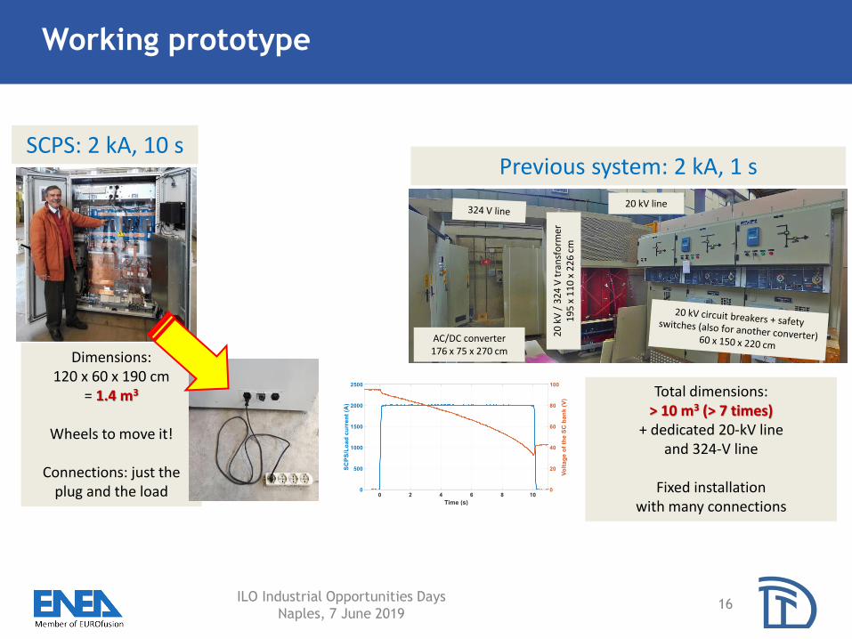
Working prototype
ILO Industrial Opportunities Days
Naples, 7 June 201916
20
kV
/ 3
24
V t
ran
sfo
rmer
19
5 x
11
0 x
22
6 c
m
AC/DC converter176 x 75 x 270 cm
20 kV line
SCPS: 2 kA, 10 sPrevious system: 2 kA, 1 s
Dimensions:120 x 60 x 190 cm
= 1.4 m3
Wheels to move it!
Connections: just the plug and the load
Total dimensions: > 10 m3 (> 7 times)
+ dedicated 20-kV line and 324-V line
Fixed installation with many connections

Rough estimation of possible final configuration
ILO Industrial Opportunities Days
Naples, 7 June 201917
• Total Energy Storage for 12 PSs: 600 MW, 3600 MJ, 960 kWh
• Moreover, ENEA has SMESs and flywheels
• Comparison:• Korea: 25 MW supercap in several facilities
• Endesa STORE, Canary Islands, Spain supercap: 4 MW, 20 MJ
• Terna, Sicilia + Sardegna supercap: 1+1 MW, 1+1 MJ
• Terna has some battery systems in order of 10 MW
• DTT could be an “electrostatic lake” (Italy has 4 hydro-storage lakes at 1 GW)
If you like to know more: www.supercap.org

Main characteristics of the base PSs
ILO Industrial Opportunities Days
Naples, 7 June 201918
Characteristic CS/PF PSs VS coil PSs IV coil PSs ELM/RWM PSs
Position Ex-vessel In-vessel equatorial Around divertor Non-axisymmetric
Load coil material Superconducting Copper Copper Copper
Number of PSs 12 2 4 To be defined
Number of quadrants 4 4 4 (2 possible) 4
Duty cycle and typical
scenarios<200s/3600s 100s/3600s Flat-top ≤40 s 100s/3600s
Ramps Up 60 s, down 30 s None To be defined None
Number of converter
transformers1 (also for more coils) 1 2 To be defined
Adopted topologyDC link storage
H-bridge
DC link storage
H-bridgeThyristor bridge
DC link
Same input power
Semiconductor
technologyIGBT (IGCT) IGBT Thyristor Silicon carbide
Energy stored in DC
link per PS>300 MJ >100 MJ None To be defined
Charger Diode or AFE Diode or AFE None Diode/thyristor
Input power <50 kW <100 kW >1 MW <1 MW
Number of basic units 12 10 5 To be defined
Current ±30 kA ±25 kA ±25 kA To be defined
No-load DC voltage 1000 V 200 V 200 V To be defined
Worst-case DC voltage 600 V 200 V 200 V To be defined
Control Fast Fast modulation Slow Fast
Controlled quantity Current or voltage Current or voltage Current Current
Supporting SNU Static None None None
Cooling Raw water Raw water Demi water Air

Layout of the coil PS area
19
Each PS has a dedicated
area 13x13 m
In each area 3-4 standard
(40 feet) containers

DC busbars and tunnels
ILO Industrial Opportunities Days
Naples, 7 June 201920
Area 13x13 m
40 feet containers
DTT Hall
DTT
Road
Container
Cover, if necessary
>3 km aluminum (or copper) bars
Critical: TF 45 kA Proposal: HTS

Assumed scenario and performances for additional heating
ILO Industrial Opportunities Days
Naples, 7 June 20192121
Poor knowledge of AH scenarios (and real efficiency), including fast variations
H&CD system Initial mix Maximum
expected upgrade
Wall-plug
efficiency η
Power factor cosϕ
ECRH 15 MW 30 MW 35-40% 0.9
ICRH 3 MW 9 MW 40% 0.9
N-NBI 7.5 MW 15 MW 40-45% 0.87
EC
N-NBI

Typical DTT scenario (and official scenario for Terna)
ILO Industrial Opportunities Days
Naples, 7 June 20192222
Typical
SSEN

Summary of PSS Calls for Tenders
ILO Industrial Opportunities Days
Naples, 7 June 20192323
2019 2020 2021 2022 2023 2024 2025
I II III IV I II III IV I II III IV I II III IV I II III IV I II III IV I II III IV
1 High-voltage line
2 Electrical substation
3 Power factor corrrection and filters
4 Electrical distribution (SSEN & PPEN)
5 Toroidal Field Coil PS
6 Toroidal Field Coil fast discharge units
7 CS/PF PSs and SNUs (some BPSs)
8 Internal Coil PSs
9 DC busbars (CS, PF, TF, IC)
10Others (dummy loads, auxiliary, transducers, …)
Color code:
Preliminary analysis
Prepare and launch the Call for Tender
Call for Tender
Design
Manufactoring and factory tests
Installation (and procedures for the HV line)
Test
Commisioning
Remember, not including:
• H&CD PSs
• ELM, RWM PSs
• LV in buildings
Short-term planning: test facility for PF, CS, TF coils
ILO Industrial Opportunities Days
Naples, 7 June 20192424
• CS and PF PSs are very different from TF PS
• Different PSs also in test facility
• Both ready by 2021 (2022)
• Proposal
1. A 40’’ container for PF6 and CS0, including SNU but with
shorter scenario (less energy)
2. A 40’’ container for 18 TF coils, including FDU but with
reduced resistance for same τ= 5 s
