power supply units, autodome vg5- and mic7000...
TRANSCRIPT
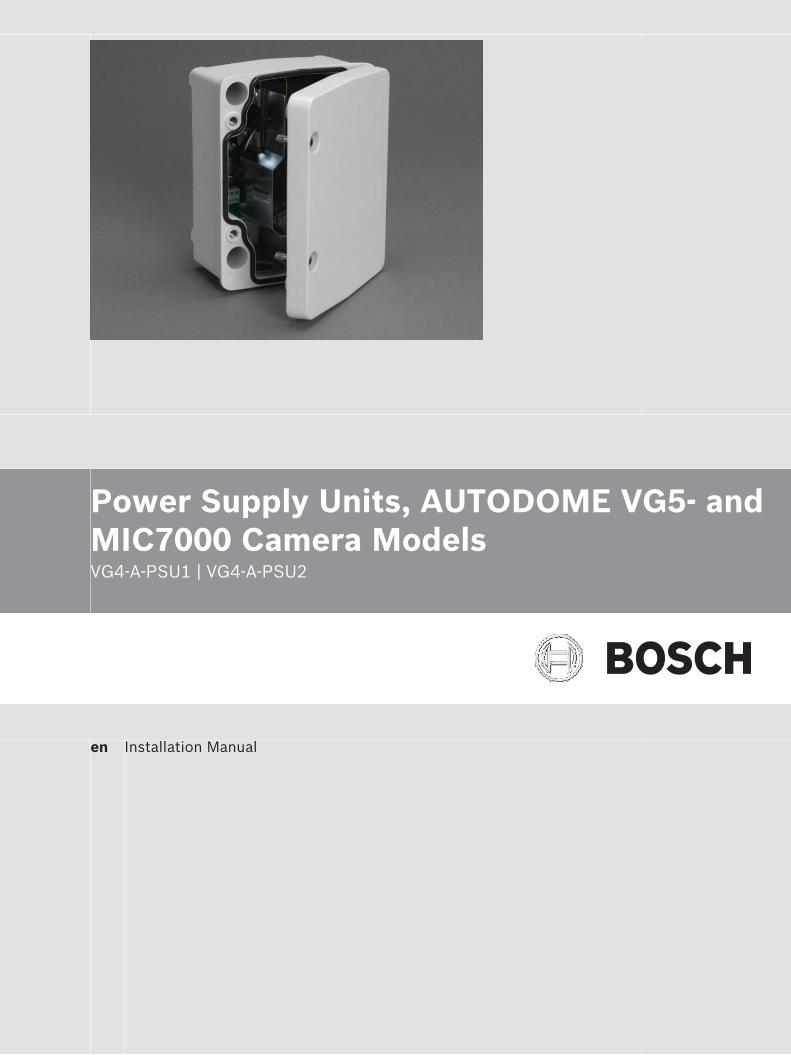
Power Supply Units, AUTODOME VG5- andMIC7000 Camera ModelsVG4-A-PSU1 | VG4-A-PSU2
en Installation Manual

Table of contents
1 Safety 41.1 Safety precautions 41.2 Important safety instructions 41.3 Important Notices 51.4 UL certification 61.5 Bosch notices 6
2 Unpacking 82.1 Parts List 82.2 Optional Parts List 82.3 Tools Required 8
3 Description 94 Pre-installation Check List 105 Mount Power Supply Box (Wall, Mast (Pole), and Corner Mounts) 126 Attach Cover Door to Power Supply Box 147 Route Wires and Attach Connectors 157.1 Methods for Routing Wires (AUTODOME Cameras ONLY) 157.2 Routing Power Wires (MIC7000 Cameras ONLY) 177.3 Wiring the Power Supply Box 187.4 Power Supply Box Connections 19
8 Video and Control Cables (AUTODOME VG5-600 Camera Models ONLY) 228.1 Using Coaxial Cable to Transmit Video and Control 228.2 Using UTP to Transmit Video and Control 228.3 Using Ethernet to Transmit Video and Control 238.4 Using Multi-mode Fiber Optic to Transmit Video and Control 238.5 Using a Fiber Optic Ethernet Media Converter to Transmit Video and Control 248.6 Controlling the AUTODOME via Biphase 258.7 Controlling the AUTODOME via the RS232 Protocol 268.8 Controlling the AUTODOME via the RS-485 Protocol 27
9 Fiber Optic Module with an RS232/RS422 Controller (AUTODOME VG5-600 CameraModels ONLY)
30
9.1 Connecting to an LTC 4629 Head End Data/Video Transceiver 309.2 Configuring the VG5 AUTODOME Camera 30
10 Audio Cables (AUTODOME Cameras ONLY, except VG5-600 Models) 33
Power Supply Units, AUTODOME VG5-and MIC7000 Camera Models
Table of Contents | en 3
Bosch Security Systems, Inc. Installation Manual 2014.05 | 2.3 | F.01U.250.895

SafetyRead, follow, and retain all of the following safety instructions. Heed all warnings on the unitand in the operating instructions before operation.
Safety precautions
Danger!
Indicates a hazardous situation which, if not avoided, will result in death or serious injury.
!Warning!
Indicates a hazardous situation which, if not avoided, could result in death or serious injury.
!
Caution!
Indicates a hazardous situation which, if not avoided, could result in minor or moderate
injury.
Notice!
Indicates a situation which, if not avoided, could result in damage to the equipment or
environment, or data loss.
Important safety instructionsRead, follow, and retain for future reference all of the following safety instructions. Heed allwarnings on the unit and in the operating instructions before operating the unit.1. Cleaning - Unplug the unit from the outlet before cleaning. Follow any instructions
provided with the unit. Generally, using a dry cloth for cleaning is sufficient but a moist,fluff-free cloth or leather shammy may also be used. Do not use liquid cleaners or aerosolcleaners.
2. Water - Do not use this unit near water, for example near a bathtub, washbowl, sink,laundry basket, in a damp or wet basement, near a swimming pool, in an outdoorinstallation, or in any area classified as a wet location. To reduce the risk of fire orelectrical shock, do not expose this unit to rain or moisture.
3. Object and liquid entry - Never push objects of any kind into this unit through openingsas they may touch dangerous voltage points or short-out parts that could result in a fireor electrical shock. Never spill liquid of any kind on the unit. Do not place objects filledwith liquids, such as vases or cups, on the unit.
4. Power connection - Protect the exit of the power connection from the unit from foottraffic, and other potential situations that could cause damage. For units intended tooperate with 230 VAC, 50 Hz, the input and output power cord must comply with thelatest versions of IEC Publication 227 or IEC Publication 245.
5. Power sources - Operate the unit only from the type of power source indicated on thelabel. Before proceeding, be sure to disconnect the power from the cable to be installedinto the unit.– For battery powered units, refer to the operating instructions.– For external power supplied units, use only the recommended or approved power
supplies.
1
1.1
1.2
4 en | SafetyPower Supply Units, AUTODOME VG5-
and MIC7000 Camera Models
2014.05 | 2.3 | F.01U.250.895 Installation Manual Bosch Security Systems, Inc.
– For limited power source units, this power source must comply with EN60950.Substitutions may damage the unit or cause fire or shock.
– If unsure of the type of power supply to use, contact your dealer or local powercompany.
6. Servicing - Do not attempt to service this unit yourself. Opening or removing covers mayexpose you to dangerous voltage or other hazards. Refer all servicing to qualified servicepersonnel.
7. Damage requiring service - Unplug the unit from the main AC power source and referservicing to qualified service personnel when any damage to the equipment has occurred,such as:– exposure to moisture, water, and/or inclement weather (rain, snow, etc.);– liquid has been spilled in or on the equipment;– an object has fallen into the unit;– unit has been dropped or the unit cabinet is damaged;– unit exhibits a distinct change in performance;– unit does not operate normally when the user correctly follows the operating
instructions.8. Replacement parts - Be sure the service technician uses replacement parts specified by
the manufacturer, or that have the same characteristics as the original parts.Unauthorized substitutions may cause fire, electrical shock, or other hazards.
9. Safety check - Safety checks should be performed upon completion of service or repairsto the unit to ensure proper operating condition.
10. Installation - Install in accordance with the manufacturer's instructions and in accordancewith applicable local codes.
11. Attachments, changes or modifications - Only use attachments/accessories specified bythe manufacturer. Any change or modification of the equipment, not expressly approvedby Bosch, could void the warranty or, in the case of an authorization agreement, authorityto operate the equipment.
Important NoticesU.S.A. models only - Section 810 of the National Electrical Code, ANSI/NFPA No.70, providesinformation regarding proper grounding of the mount and supporting structure, grounding ofthe coax to a discharge unit, size of grounding conductors, location of discharge unit,connection to grounding electrodes, and requirements for the grounding electrode.
Disposal - Your Bosch product was developed andmanufactured with high-quality material and components thatcan be recycled and reused. This symbol means thatelectronic and electrical appliances, which have reached theend of their working life, must be collected and disposed ofseparately from household waste material. Separatecollecting systems are usually in place for disused electronicand electrical products. Please dispose of these units at anenvironmentally compatible recycling facility, per EuropeanDirective 2002/96/EC
Environmental statement - Bosch has a strong commitment towards the environment. Thisunit has been designed to respect the environment as much as possible.
1.3
Power Supply Units, AUTODOME VG5-and MIC7000 Camera Models
Safety | en 5
Bosch Security Systems, Inc. Installation Manual 2014.05 | 2.3 | F.01U.250.895

Power lines: An outdoor system should not be located in the vicinity of overhead power lines,electrical lights, or power circuits, or where it may contact such power lines or circuits. Wheninstalling an outdoor system, extreme care should be taken to keep from touching power linesor circuits, as this contact may be fatal. U.S.A. models only - refer to the National ElectricalCode Article 820 regarding installation of CATV systems.SELV - All the input/output ports are Safety Extra Low Voltage (SELV) circuits. SELV circuitsshould only be connected to other SELV circuits.Avoid connecting the SELV circuit to the Telephone Network Voltage (TNV) circuits.System ground/Safety ground
System (video) ground is indicated by the symbol .
Safety (power) ground is indicated by the symbol .The system ground is only used to comply with safety standards or installation practices incertain countries. Bosch does not recommend connecting system ground to safety groundunless it is explicitly required. However, if the system ground and safety ground are connectedand grounding loops are causing interference in the video signal, use an isolation transformer(available separately from Bosch).
!
Caution!
Connecting System ground to Safety ground may result in ground loops that can disrupt the
CCTV system.
UL certificationDisclaimerUnderwriter Laboratories Inc. (“UL”) has not tested the performance or reliability of thesecurity or signaling aspects of this product. UL has only tested fire, shock and/or casualtyhazards as outlined in UL's Standard(s) for Safety for Closed Circuit Television Equipment, UL2044. UL Certification does not cover the performance or reliability of the security or signalingaspects of this product.UL MAKES NO REPRESENTATIONS, WARRANTIES, OR CERTIFICATIONS WHATSOEVERREGARDING THE PERFORMANCE OR RELIABILITY OF ANY SECURITY OR SIGNALING RELATEDFUNCTIONS OF THIS PRODUCT.
DisclaimerUnderwriter Laboratories Inc. (“UL”) has not tested the performance or reliability of thesecurity or signaling aspects of this product. UL has only tested fire, shock and/or casualtyhazards as outlined in UL's Standard(s) for Safety for Information Technology Equipment, UL60950-1. UL Certification does not cover the performance or reliability of the security orsignaling aspects of this product.UL MAKES NO REPRESENTATIONS, WARRANTIES, OR CERTIFICATIONS WHATSOEVERREGARDING THE PERFORMANCE OR RELIABILITY OF ANY SECURITY OR SIGNALING-RELATEDFUNCTIONS OF THIS PRODUCT.
Bosch noticesCopyrightThis manual is the intellectual property of Bosch Security Systems and is protected bycopyright. All rights reserved.
TrademarksAll hardware and software product names used in this document are likely to be registeredtrademarks and must be treated accordingly.
1.4
1.5
6 en | SafetyPower Supply Units, AUTODOME VG5-
and MIC7000 Camera Models
2014.05 | 2.3 | F.01U.250.895 Installation Manual Bosch Security Systems, Inc.
Note:This manual has been compiled with great care and the information it contains has beenthoroughly verified. The text was complete and correct at the time of printing. The ongoingdevelopment of the products may mean that the content of the user guide can change withoutnotice. Bosch Security Systems accepts no liability for damage resulting directly or indirectlyfrom faults, incompleteness or discrepancies between the user guide and the productdescribed.
More informationFor more information please contact the nearest Bosch Security Systems location or visitwww.boschsecurity.com
Power Supply Units, AUTODOME VG5-and MIC7000 Camera Models
Safety | en 7
Bosch Security Systems, Inc. Installation Manual 2014.05 | 2.3 | F.01U.250.895
UnpackingThis equipment should be unpacked and handled with care. If an item appears to have beendamaged in shipment, notify the shipper immediately.Verify that all the parts listed in the product's Parts List below are included. If any items aremissing, notify your Bosch Security Systems Sales or Customer Service Representative.The original packing carton is the safest container in which to transport the unit and must beused if returning the unit for service. Save it for possible future use.
Parts ListEach VG4-A-PSU power supply box is NEMA-rated and ships with an enclosure cover and:– Two (2) blanking plugs that fit a ½” conduit hole– Four (4) blanking plugs that fit a ¾” conduit hole– One (1) Installation Guide– One (1) Quick Installation Guide (valid for AUTODOME cameras only)
Optional Parts ListThe following table lists the optional equipment for use with the power supply boxes(applicable only for models that power AUTODOME cameras):
Option Part Number
Trim skirt VGA-A-TSKIRT
Replacement power supply box cover VG4-SBOX-COVER
Analog Multimode Fiber Optic Kit VGA-FIBER-AN
Ethernet Media Converter Kit VG4-SFPSCKT
Note: The fiber optic kits are mounted inside the power supply box. Refer to the individual kitfor installation instructions.
Tools Required– Small straight blade screwdrivers ~ 2.5 mm (0.1 in.) – 3.1 mm (1/8 in.)– Medium straight blade screwdriver– No. 1 and No. 2 Phillips screwdrivers– Socket wrench and 9/16 in. socket– Power drill– Water tight conduits and fittings that meet NEMA 4 standards
2
2.1
2.2
2.3
8 en | UnpackingPower Supply Units, AUTODOME VG5-
and MIC7000 Camera Models
2014.05 | 2.3 | F.01U.250.895 Installation Manual Bosch Security Systems, Inc.
DescriptionThis manual describes how to install a VG4-A-PSUx power supply box for an AUTODOME VG5-camera, or a VG4-A-PSU1 or VG4-A-PSU2 for a MIC7000 camera. Any variations to theinstallation procedures are noted. For AUTODOME cameras, these power supply boxes are intended for use with the VGA-PEND_ARM Arm Mount, VGA-A-9543 Pipe Mount, and the VG4-A-9230 or VGA-ROOF-MOUNTRoof Parapet Mount. For complete installation, mounting, and wiring information forAUTODOME cameras, refer to the VG5 Series AUTODOME Installation Manual included with thepackaging of the AUTODOME pendant. The table below describes each model of VG4-A-PSU power supply:
Part Number Rating Applicable cameras
VG4-A-PSU1 120 VAC, 60 Hz, 1.2 A AUTODOME cameras;MIC7000 cameras
VG4-A-PSU2 230 VAC, 50 Hz, 0.6 A AUTODOME cameras;MIC7000 cameras
3
Power Supply Units, AUTODOME VG5-and MIC7000 Camera Models
Description | en 9
Bosch Security Systems, Inc. Installation Manual 2014.05 | 2.3 | F.01U.250.895
Pre-installation Check List
!
Caution!
Installation must be made by qualified personnel and conform to ANSI/NFPA 70 (the National
Electrical Code® (NEC)), Canadian Electrical Code, Part I (also called CE Code or CSA C22.1),
and all applicable local codes. Bosch Security Systems, Inc. accepts no liability for any
damages or losses caused by incorrect or improper installation.
1. Determine the location and distance for the power supply box based on its voltage andcurrent consumption.
Power
115/230 VAC
Copper Wire To comply with local codes.
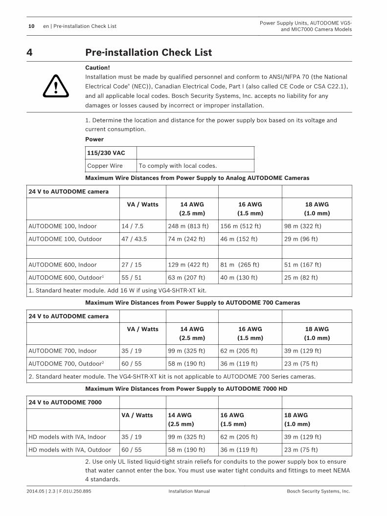
Maximum Wire Distances from Power Supply to Analog AUTODOME Cameras
24 V to AUTODOME camera
VA / Watts 14 AWG(2.5 mm)
16 AWG(1.5 mm)
18 AWG(1.0 mm)
AUTODOME 100, Indoor 14 / 7.5 248 m (813 ft) 156 m (512 ft) 98 m (322 ft)
AUTODOME 100, Outdoor 47 / 43.5 74 m (242 ft) 46 m (152 ft) 29 m (96 ft)
AUTODOME 600, Indoor 27 / 15 129 m (422 ft) 81 m (265 ft) 51 m (167 ft)
AUTODOME 600, Outdoor1 55 / 51 63 m (207 ft) 40 m (130 ft) 25 m (82 ft)
1. Standard heater module. Add 16 W if using VG4-SHTR-XT kit.
Maximum Wire Distances from Power Supply to AUTODOME 700 Cameras
24 V to AUTODOME camera
VA / Watts 14 AWG(2.5 mm)
16 AWG(1.5 mm)
18 AWG(1.0 mm)
AUTODOME 700, Indoor 35 / 19 99 m (325 ft) 62 m (205 ft) 39 m (129 ft)
AUTODOME 700, Outdoor2 60 / 55 58 m (190 ft) 36 m (119 ft) 23 m (75 ft)
2. Standard heater module. The VG4-SHTR-XT kit is not applicable to AUTODOME 700 Series cameras.
Maximum Wire Distances from Power Supply to AUTODOME 7000 HD
24 V to AUTODOME 7000
VA / Watts 14 AWG (2.5 mm)
16 AWG (1.5 mm)
18 AWG (1.0 mm)
HD models with IVA, Indoor 35 / 19 99 m (325 ft) 62 m (205 ft) 39 m (129 ft)
HD models with IVA, Outdoor 60 / 55 58 m (190 ft) 36 m (119 ft) 23 m (75 ft)
2. Use only UL listed liquid-tight strain reliefs for conduits to the power supply box to ensurethat water cannot enter the box. You must use water tight conduits and fittings to meet NEMA4 standards.
4
10 en | Pre-installation Check ListPower Supply Units, AUTODOME VG5-
and MIC7000 Camera Models
2014.05 | 2.3 | F.01U.250.895 Installation Manual Bosch Security Systems, Inc.

Notice!
Power and I/O cabling must be routed separately inside different permanently earthed metal
conduits.
3. Install all rough wiring, including: power, control, video coax, alarms I/O, relay I/O, and fiberoptic cabling. For video and control protocol methods for AUTODOME cameras, refer to Videoand Control Cables (AUTODOME VG5-600 Camera Models ONLY), page 22.4. For an analog AUTODOME camera only: If you plan to use the RS-232 or RS-485 protocolto control the camera, refer to Controlling the AUTODOME via the RS232 Protocol, page 26, orControlling the AUTODOME via the RS-485 Protocol, page 27, for instructions on configuringthe camera to accept these protocols.
!
Warning!
External mains power cables are to be installed in accordance to NEC, ANSI/NFPA70 (for US
application) and Canadian Electrical Code, Part I, CSA C22.1 (for CAN application) and in
accordance to local country codes for all other countries.
Branch circuit protection incorporating a 20 A, 2-pole Listed Circuit Breaker or Branch Rated
Fuses are required as part of the building installation. A readily accessible 2-pole disconnect
device with a contact separation of at least 3 mm must be incorporated.
5. Purchase the appropriate mounting hardware to use, depending on the location of thepower supply box.
Power Supply Units, AUTODOME VG5-and MIC7000 Camera Models
Pre-installation Check List | en 11
Bosch Security Systems, Inc. Installation Manual 2014.05 | 2.3 | F.01U.250.895
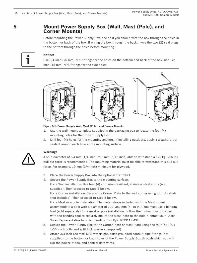
Mount Power Supply Box (Wall, Mast (Pole), andCorner Mounts)Before mounting the Power Supply Box, decide if you should wire the box through the holes inthe bottom or back of the box. If wiring the box through the back, move the two (2) seal plugsto the bottom through the holes before mounting.
Notice!
Use 3/4-inch (20-mm) NPS fittings for the holes on the bottom and back of the box. Use 1/2-
inch (15-mm) NPS fittings for the side holes.
Figure 5.1: Power Supply Wall, Mast (Pole), and Corner Mounts
1. Use the wall mount template supplied in the packaging box to locate the four (4)mounting holes for the Power Supply Box.
2. Drill four (4) holes for the mounting anchors. If installing outdoors, apply a weatherproofsealant around each hole at the mounting surface.
!
Warning!
A stud diameter of 6.4 mm (1/4 inch) to 8 mm (5/16 inch) able to withstand a 120 kg (265 lb)
pull-out force is recommended. The mounting material must be able to withstand this pull out
force. For example, 19-mm (3/4-inch) minimum for plywood.
3. Place the Power Supply Box into the optional Trim Skirt.4. Secure the Power Supply Box to the mounting surface.
For a Wall installation: Use four (4) corrosion-resistant, stainless steel studs (notsupplied). Then proceed to Step 5 below.For a Corner installation: Secure the Corner Plate to the wall corner using four (4) studs(not included). Then proceed to Step 5 below.For a Mast or a pole installation: The metal straps included with the Mast mountaccommodate a pole with a diameter of 100–380 mm (4–15 in.). You must use a bandingtool (sold separately) for a mast or pole installation. Follow the instructions providedwith the banding tool to securely mount the Mast Plate to the pole. Contact your BoschSales Representative to order Banding Tool P/N TC9311PM3T.
5. Secure the Power Supply Box to the Corner Plate or Mast Plate using the four (4) 3/8 x1-3/4-inch bolts and split lock washers (supplied).
6. Attach 3/4-inch (20-mm) NPS watertight, earth-grounded conduit pipe fittings (notsupplied) to the bottom or back holes of the Power Supply Box through which you willrun the power, video, and control data wires.
5
12 en | Mount Power Supply Box (Wall, Mast (Pole), and Corner Mounts)Power Supply Units, AUTODOME VG5-
and MIC7000 Camera Models
2014.05 | 2.3 | F.01U.250.895 Installation Manual Bosch Security Systems, Inc.
!
Warning!
For units intended to be installed outdoors: All wiring (power and I/O cabling) connecting to
the unit must be routed separately inside different permanently earthed metal conduits (not
supplied).
Power Supply Units, AUTODOME VG5-and MIC7000 Camera Models
Mount Power Supply Box (Wall, Mast (Pole), and Corner Mounts) | en 13
Bosch Security Systems, Inc. Installation Manual 2014.05 | 2.3 | F.01U.250.895
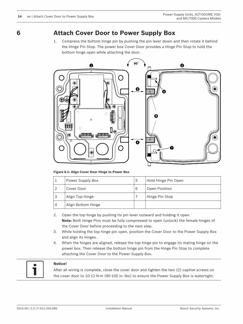
Attach Cover Door to Power Supply Box1. Compress the bottom hinge pin by pushing the pin lever down and then rotate it behind
the Hinge Pin Stop. The power box Cover Door provides a Hinge Pin Stop to hold thebottom hinge open while attaching the door.
GND T XD R XD C+ C- GND T XD R XD C+ C-
(FU
SE
) (F
US
E)
(FU
SE
)
90o
HT
R
DO
ME
LINE NC NEUT
Figure 6.1: Align Cover Door Hinge to Power Box
1 Power Supply Box 5 Hold Hinge Pin Open
2 Cover Door 6 Open Position
3 Align Top Hinge 7 Hinge Pin Stop
4 Align Bottom Hinge
2. Open the top hinge by pushing its pin lever outward and holding it open.Note: Both Hinge Pins must be fully compressed to open (unlock) the female hinges ofthe Cover Door before proceeding to the next step.
3. While holding the top hinge pin open, position the Cover Door to the Power Supply Boxand align its hinges.
4. When the hinges are aligned, release the top hinge pin to engage its mating hinge on thepower box. Then release the bottom hinge pin from the Hinge Pin Stop to completeattaching the Cover Door to the Power Supply Box.
Notice!
After all wiring is complete, close the cover door and tighten the two (2) captive screws on
the cover door to 10-12 N-m (90-105 in.-lbs) to ensure the Power Supply Box is watertight.
6
14 en | Attach Cover Door to Power Supply BoxPower Supply Units, AUTODOME VG5-
and MIC7000 Camera Models
2014.05 | 2.3 | F.01U.250.895 Installation Manual Bosch Security Systems, Inc.
Route Wires and Attach ConnectorsPower wires must be routed to the left (front) side of the Power Supply Box through aseparate electrically earth-grounded conduit. All video, control, and alarm wires must berouted through a second electrically earth-grounded conduit to the right side of the box.
!
Warning!
External interconnecting cables are to be installed in accordance to NEC, ANSI/NFPA70 (for
US application) and Canadian Electrical Code, Part I, CSA C22.1 (for CAN application) and in
accordance to local country codes for all other countries.
Branch circuit protection incorporating a 20 A, 2-pole Listed Circuit Breaker or Branch Rated
Fuses are required as part of the building installation. A readily accessible 2-pole disconnect
device with a contact separation of at least 3 mm (0.12 in.) must be incorporated.
Methods for Routing Wires (AUTODOME Cameras ONLY)There are two possible methods to route the video, control, and alarm wires:Method One is to route the video, control, and alarm wires through the conduit fitting on theright (front) side of the Power Supply Box and out to the AUTODOME Interface Board.
7
7.1
Power Supply Units, AUTODOME VG5-and MIC7000 Camera Models
Route Wires and Attach Connectors | en 15
Bosch Security Systems, Inc. Installation Manual 2014.05 | 2.3 | F.01U.250.895
GND TXD RXD C+ C-GND TXD RXD C+ C-
P101
P106 P105
P1
07
XF
10
2X
F1
03
XF
10
1
5 4
3 2
1
J1
03
J1
03
J1
03
J102
J10
1
(LED)
HT
R D
OM
E
(FU
SE
)(F
US
E)
(FU
SE
)(F
US
E)
LINE NC NEUT
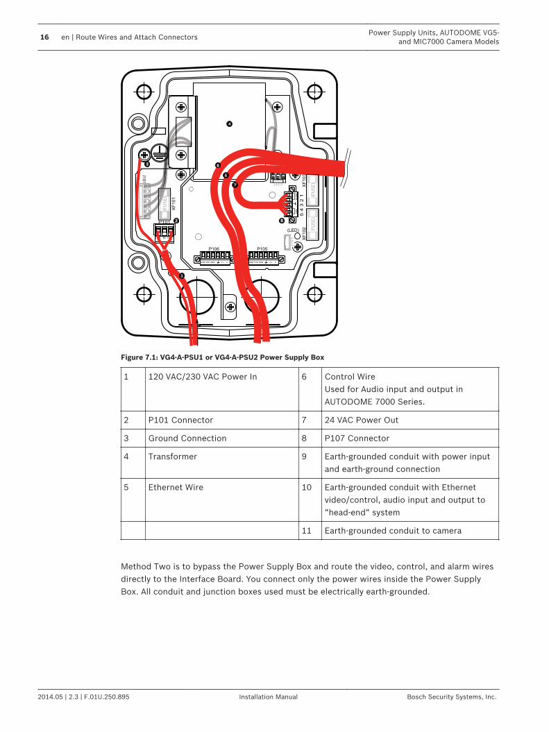
Figure 7.1: VG4-A-PSU1 or VG4-A-PSU2 Power Supply Box
1 120 VAC/230 VAC Power In 6 Control WireUsed for Audio input and output inAUTODOME 7000 Series.
2 P101 Connector 7 24 VAC Power Out
3 Ground Connection 8 P107 Connector
4 Transformer 9 Earth-grounded conduit with power inputand earth-ground connection
5 Ethernet Wire 10 Earth-grounded conduit with Ethernetvideo/control, audio input and output to“head-end“ system
11 Earth-grounded conduit to camera
Method Two is to bypass the Power Supply Box and route the video, control, and alarm wiresdirectly to the Interface Board. You connect only the power wires inside the Power SupplyBox. All conduit and junction boxes used must be electrically earth-grounded.
16 en | Route Wires and Attach ConnectorsPower Supply Units, AUTODOME VG5-
and MIC7000 Camera Models
2014.05 | 2.3 | F.01U.250.895 Installation Manual Bosch Security Systems, Inc.
GND TXD RXD C+ C-GND TXD RXD C+ C-
P101
P106 P105
P1
07
XF
10
2X
F1
03
XF
10
1
5 4
3 2
1
J1
03
J1
03
J1
03
J102
J10
1
(LED)
HT
R
DO
ME
(FU
SE
)(F
US
E)
(FU
SE
)(F
US
E)
BNC
J1
02
P1
07
P1
01
P10
2P
103
P1
04
P106
J101
AGNDA7A6A5A4A3
AGND
OUT 3
OUT 2
OUT 1
P10
5
LINE NC NEUT
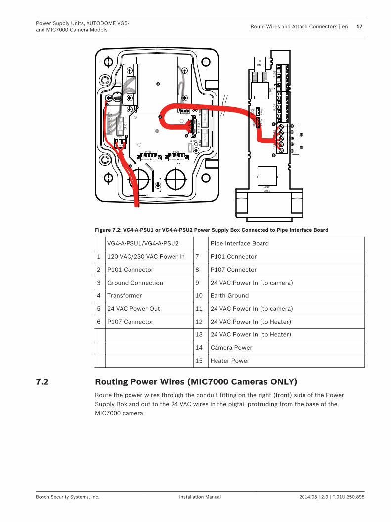
Figure 7.2: VG4-A-PSU1 or VG4-A-PSU2 Power Supply Box Connected to Pipe Interface Board
VG4-A-PSU1/VG4-A-PSU2 Pipe Interface Board
1 120 VAC/230 VAC Power In 7 P101 Connector
2 P101 Connector 8 P107 Connector
3 Ground Connection 9 24 VAC Power In (to camera)
4 Transformer 10 Earth Ground
5 24 VAC Power Out 11 24 VAC Power In (to camera)
6 P107 Connector 12 24 VAC Power In (to Heater)
13 24 VAC Power In (to Heater)
14 Camera Power
15 Heater Power
Routing Power Wires (MIC7000 Cameras ONLY)Route the power wires through the conduit fitting on the right (front) side of the PowerSupply Box and out to the 24 VAC wires in the pigtail protruding from the base of theMIC7000 camera.
7.2
Power Supply Units, AUTODOME VG5-and MIC7000 Camera Models
Route Wires and Attach Connectors | en 17
Bosch Security Systems, Inc. Installation Manual 2014.05 | 2.3 | F.01U.250.895
GND TXD RXD C+ C-GND TXD RXD C+ C-
P101
P106 P105
P1
07
XF
10
2X
F1
03
XF
10
1
5 4
3 2
1
J1
03
J1
03
J1
03
J102
J10
1
(LED)
H/A
UX
DO
ME
24V NC 24V
(FU
SE
)(F
US
E)
(FU
SE
)
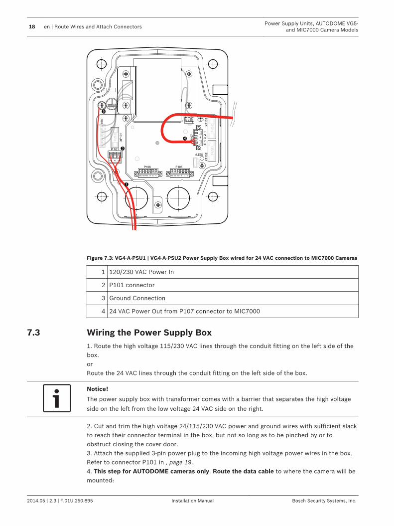
Figure 7.3: VG4-A-PSU1 | VG4-A-PSU2 Power Supply Box wired for 24 VAC connection to MIC7000 Cameras
1 120/230 VAC Power In
2 P101 connector
3 Ground Connection
4 24 VAC Power Out from P107 connector to MIC7000
Wiring the Power Supply Box1. Route the high voltage 115/230 VAC lines through the conduit fitting on the left side of thebox.orRoute the 24 VAC lines through the conduit fitting on the left side of the box.
Notice!
The power supply box with transformer comes with a barrier that separates the high voltage
side on the left from the low voltage 24 VAC side on the right.
2. Cut and trim the high voltage 24/115/230 VAC power and ground wires with sufficient slackto reach their connector terminal in the box, but not so long as to be pinched by or toobstruct closing the cover door.3. Attach the supplied 3-pin power plug to the incoming high voltage power wires in the box.Refer to connector P101 in , page 19.4. This step for AUTODOME cameras only. Route the data cable to where the camera will bemounted:
7.3
18 en | Route Wires and Attach ConnectorsPower Supply Units, AUTODOME VG5-
and MIC7000 Camera Models
2014.05 | 2.3 | F.01U.250.895 Installation Manual Bosch Security Systems, Inc.
– Analog AUTODOME: If you are using UTP for video, route the UTP cable. Refer to UsingUTP to Transmit Video and Control, page 22 for fiber optic specifications.
– IP AUTODOME: Route the Ethernet cable. Refer to Using Ethernet to Transmit Video andControl, page 23 for specifications.
5. Route the low power 24 VAC wires from the right side of the power supply box out to wherethe camera will be mounted. Attach the supplied 5-pin 24 VAC Dome plug to the wire endsinside the box. Refer to connector P107 in , page 19.
Notice!
All video, control, and alarm wires either pass through the power supply box or by-pass it and
connect directly to the Pipe Interface Board.
Power Supply Box ConnectionsThe following figure is a detailed illustration of the power supply box, which includes the fusespecifications.
7.4
Power Supply Units, AUTODOME VG5-and MIC7000 Camera Models
Route Wires and Attach Connectors | en 19
Bosch Security Systems, Inc. Installation Manual 2014.05 | 2.3 | F.01U.250.895
CONTROL
TO DOMEO DOMO DOM
CONTROL
IN/OUT
GND TXD
RXD
C+
C-
P101
1 2 3
6 5 4 3 2 1 4 3 2 1
P106 P105
P1
07
XF1
02
XF1
03
XF1
01
5 4
3 2
1
J1
03
J1
03
J1
03
J1
03
J102
J101
J101
J101
J101
J101
J101
J101
J101
J101
J101
J101
J101
J101
J101
J101
J101
J101
J101
J101
J101
J101
J101
J101
J101
J101
J101
J101
J101
J101
J101
J101
J101
J101
J101
J101
J101
J101
J101
J101
J101
J101
(LED)
6 5 4 3 2 1
GND TXD RXD C+ C- XD XD XD XD
H/A
UX
DO
ME
(FU
SE
)(F
US
E)
(FU
SE
)(F
US
E)
(FU
SE
)(F
US
E)
(FU
SE
)(F
US
E)
(FU
SE
)(F
US
E)
(FU
SE
)
(FU
SE
)(F
US
E)
(FU
SE
)(F
US
E)
(FU
SE
)(F
US
E)
24V NC 24V
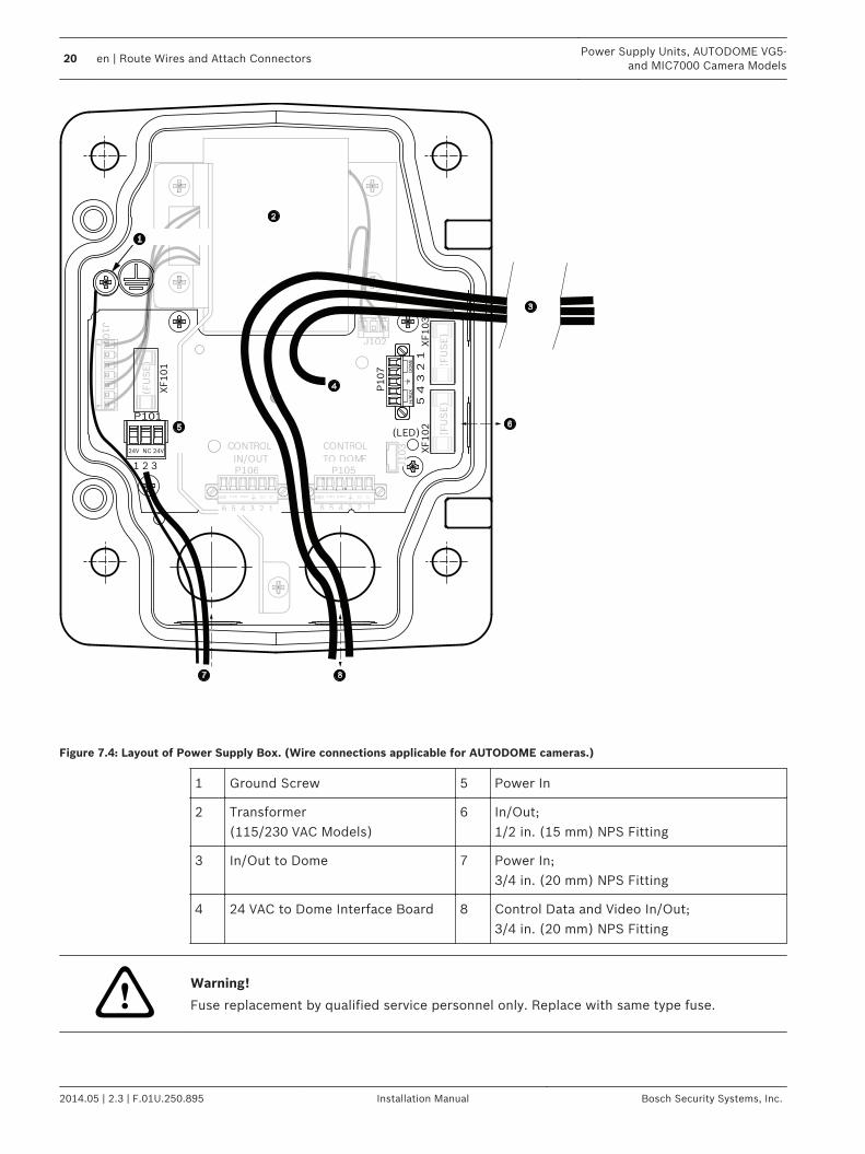
Figure 7.4: Layout of Power Supply Box. (Wire connections applicable for AUTODOME cameras.)
1 Ground Screw 5 Power In
2 Transformer (115/230 VAC Models)
6 In/Out; 1/2 in. (15 mm) NPS Fitting
3 In/Out to Dome 7 Power In; 3/4 in. (20 mm) NPS Fitting
4 24 VAC to Dome Interface Board 8 Control Data and Video In/Out; 3/4 in. (20 mm) NPS Fitting
!Warning!
Fuse replacement by qualified service personnel only. Replace with same type fuse.
20 en | Route Wires and Attach ConnectorsPower Supply Units, AUTODOME VG5-
and MIC7000 Camera Models
2014.05 | 2.3 | F.01U.250.895 Installation Manual Bosch Security Systems, Inc.
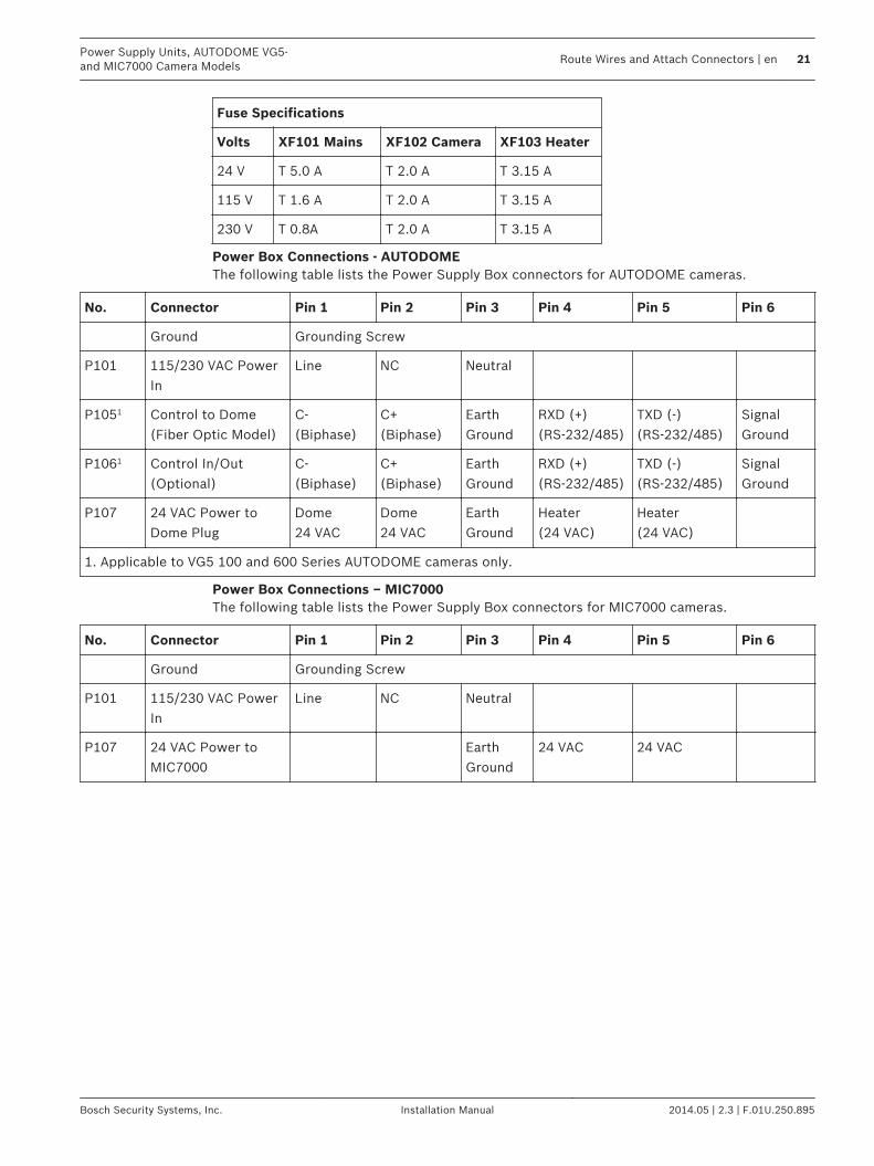
Fuse Specifications
Volts XF101 Mains XF102 Camera XF103 Heater
24 V T 5.0 A T 2.0 A T 3.15 A
115 V T 1.6 A T 2.0 A T 3.15 A
230 V T 0.8A T 2.0 A T 3.15 A
Power Box Connections - AUTODOMEThe following table lists the Power Supply Box connectors for AUTODOME cameras.
No. Connector Pin 1 Pin 2 Pin 3 Pin 4 Pin 5 Pin 6
Ground Grounding Screw
P101 115/230 VAC PowerIn
Line NC Neutral
P1051 Control to Dome(Fiber Optic Model)
C-(Biphase)
C+(Biphase)
EarthGround
RXD (+)(RS-232/485)
TXD (-)(RS-232/485)
SignalGround
P1061 Control In/Out(Optional)
C-(Biphase)
C+(Biphase)
EarthGround
RXD (+)(RS-232/485)
TXD (-)(RS-232/485)
SignalGround
P107 24 VAC Power toDome Plug
Dome24 VAC
Dome24 VAC
EarthGround
Heater(24 VAC)
Heater(24 VAC)
1. Applicable to VG5 100 and 600 Series AUTODOME cameras only.
Power Box Connections – MIC7000The following table lists the Power Supply Box connectors for MIC7000 cameras.
No. Connector Pin 1 Pin 2 Pin 3 Pin 4 Pin 5 Pin 6
Ground Grounding Screw
P101 115/230 VAC PowerIn
Line NC Neutral
P107 24 VAC Power toMIC7000
EarthGround
24 VAC 24 VAC
Power Supply Units, AUTODOME VG5-and MIC7000 Camera Models
Route Wires and Attach Connectors | en 21
Bosch Security Systems, Inc. Installation Manual 2014.05 | 2.3 | F.01U.250.895
Video and Control Cables (AUTODOME VG5-600Camera Models ONLY)This chapter applies only to AUTODOME cameras.
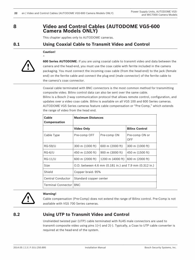
Using Coaxial Cable to Transmit Video and Control
!
Caution!
^
600 Series AUTODOME: If you are using coaxial cable to transmit video and data between the
camera and the head-end, you must use the coax cable with ferrite included in the camera
packaging. You must connect the incoming coax cable (from the head-end) to the jack (female
end) on the ferrite cable and connect the plug end (male connector) of the ferrite cable to
the camera’s coax connector.
Coaxial cable terminated with BNC connectors is the most common method for transmittingcomposite video. Bilinx control data can also be sent over the same cable.Bilinx is a Bosch 2-way communication protocol that allows remote control, configuration, andupdates over a video coax cable. Bilinx is available on all VG5 100 and 600 Series cameras.AUTODOME VG5 Series cameras feature cable compensation or “Pre-Comp,” which extendsthe range of video from the head end.
CableCompensation
Maximum Distances
Video Only Bilinx Control
Cable Type Pre-comp OFF Pre-comp ON Pre-comp ON orOFF
RG-59/U 300 m (1000 ft) 600 m (2000 ft) 300 m (1000 ft)
RG-6/U 450 m (1500 ft) 900 m (3000 ft) 450 m (1500 ft)
RG-11/U 600 m (2000 ft) 1200 m (4000 ft) 600 m (2000 ft)
Size O.D. between 4.6 mm (0.181 in.) and 7.9 mm (0.312 in.)
Shield Copper braid: 95%
Central Conductor Standard copper center
Terminal Connector BNC
!Warning!
Cable compensation (Pre-Comp) does not extend the range of Bilinx control. Pre-Comp is not
available with VG5 700 Series cameras.
Using UTP to Transmit Video and ControlUnshielded twisted pair (UTP) cable terminated with RJ45 male connectors are used totransmit composite video using pins 1(+) and 2(-). Typically, a Coax to UTP cable converter isrequired at the head-end of the system.
8
8.1
8.2
22 en | Video and Control Cables (AUTODOME VG5-600 Camera Models ONLY)Power Supply Units, AUTODOME VG5-
and MIC7000 Camera Models
2014.05 | 2.3 | F.01U.250.895 Installation Manual Bosch Security Systems, Inc.
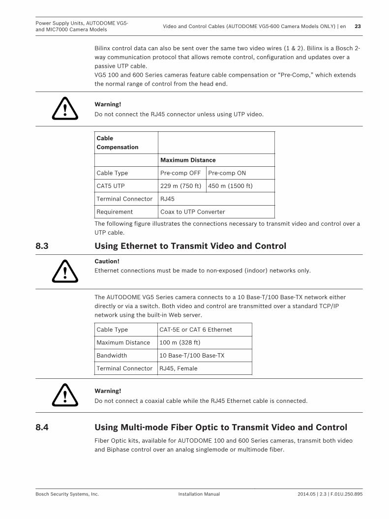
Bilinx control data can also be sent over the same two video wires (1 & 2). Bilinx is a Bosch 2-way communication protocol that allows remote control, configuration and updates over apassive UTP cable.VG5 100 and 600 Series cameras feature cable compensation or “Pre-Comp,” which extendsthe normal range of control from the head end.
!Warning!
Do not connect the RJ45 connector unless using UTP video.
CableCompensation
Maximum Distance
Cable Type Pre-comp OFF Pre-comp ON
CAT5 UTP 229 m (750 ft) 450 m (1500 ft)
Terminal Connector RJ45
Requirement Coax to UTP Converter
The following figure illustrates the connections necessary to transmit video and control over aUTP cable.
Using Ethernet to Transmit Video and Control
!
Caution!
Ethernet connections must be made to non-exposed (indoor) networks only.
The AUTODOME VG5 Series camera connects to a 10 Base-T/100 Base-TX network eitherdirectly or via a switch. Both video and control are transmitted over a standard TCP/IPnetwork using the built-in Web server.
Cable Type CAT-5E or CAT 6 Ethernet
Maximum Distance 100 m (328 ft)
Bandwidth 10 Base-T/100 Base-TX
Terminal Connector RJ45, Female
!Warning!
Do not connect a coaxial cable while the RJ45 Ethernet cable is connected.
Using Multi-mode Fiber Optic to Transmit Video and ControlFiber Optic kits, available for AUTODOME 100 and 600 Series cameras, transmit both videoand Biphase control over an analog singlemode or multimode fiber.
8.3
8.4
Power Supply Units, AUTODOME VG5-and MIC7000 Camera Models
Video and Control Cables (AUTODOME VG5-600 Camera Models ONLY) | en 23
Bosch Security Systems, Inc. Installation Manual 2014.05 | 2.3 | F.01U.250.895
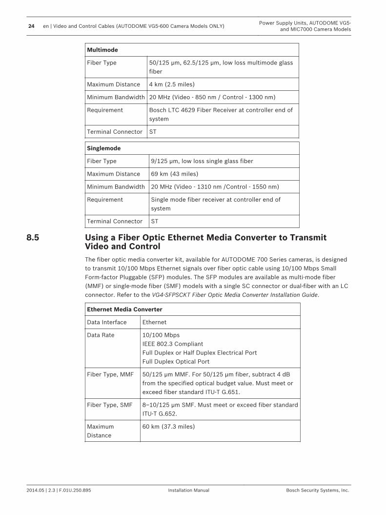
Multimode
Fiber Type 50/125 µm, 62.5/125 µm, low loss multimode glassfiber
Maximum Distance 4 km (2.5 miles)
Minimum Bandwidth 20 MHz (Video - 850 nm / Control - 1300 nm)
Requirement Bosch LTC 4629 Fiber Receiver at controller end ofsystem
Terminal Connector ST
Singlemode
Fiber Type 9/125 µm, low loss single glass fiber
Maximum Distance 69 km (43 miles)
Minimum Bandwidth 20 MHz (Video - 1310 nm /Control - 1550 nm)
Requirement Single mode fiber receiver at controller end ofsystem
Terminal Connector ST
Using a Fiber Optic Ethernet Media Converter to TransmitVideo and ControlThe fiber optic media converter kit, available for AUTODOME 700 Series cameras, is designedto transmit 10/100 Mbps Ethernet signals over fiber optic cable using 10/100 Mbps SmallForm-factor Pluggable (SFP) modules. The SFP modules are available as multi-mode fiber(MMF) or single-mode fiber (SMF) models with a single SC connector or dual-fiber with an LCconnector. Refer to the VG4-SFPSCKT Fiber Optic Media Converter Installation Guide.
Ethernet Media Converter
Data Interface Ethernet
Data Rate 10/100 MbpsIEEE 802.3 CompliantFull Duplex or Half Duplex Electrical PortFull Duplex Optical Port
Fiber Type, MMF 50/125 µm MMF. For 50/125 µm fiber, subtract 4 dBfrom the specified optical budget value. Must meet orexceed fiber standard ITU-T G.651.
Fiber Type, SMF 8–10/125 µm SMF. Must meet or exceed fiber standardITU-T G.652.
MaximumDistance
60 km (37.3 miles)
8.5
24 en | Video and Control Cables (AUTODOME VG5-600 Camera Models ONLY)Power Supply Units, AUTODOME VG5-
and MIC7000 Camera Models
2014.05 | 2.3 | F.01U.250.895 Installation Manual Bosch Security Systems, Inc.
Ethernet Media Converter
Requirement Media converter receiver (CNFE2MC/IN) at controllerend of system
TerminalConnection
Duplex LC or Single SC
Controlling the AUTODOME via Biphase(Shielded 2-wire, half-duplex, multi-drop, 5000 ft. cable limit)Biphase is the standard Bosch protocol used to send Pan/Tilt/Zoom control over 2-wireshielded twisted pair (STP) terminated with a 100 Ω terminal resistor.The cameras has a 100 Ω termination resistor between the Biphase C+ and C- terminals.
!
Caution!
The Biphase shield must be connected to the head end only.
Cable Type STP - Shielded Twisted Pair
Distance 1524 m (5000 ft) Belden 8760 recommended
Transmission Rate 31.25 KHz
Gage 1.02 mm (18 AWG)
Termination 100 Ω
Terminal Connector Screw terminals
Voltage 4 Vp-p
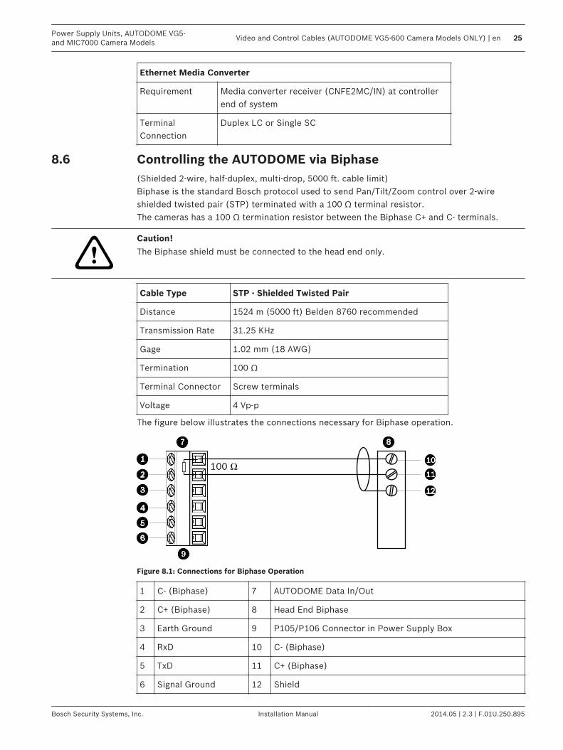
The figure below illustrates the connections necessary for Biphase operation.
100 Ω
Figure 8.1: Connections for Biphase Operation
1 C- (Biphase) 7 AUTODOME Data In/Out
2 C+ (Biphase) 8 Head End Biphase
3 Earth Ground 9 P105/P106 Connector in Power Supply Box
4 RxD 10 C- (Biphase)
5 TxD 11 C+ (Biphase)
6 Signal Ground 12 Shield
8.6
Power Supply Units, AUTODOME VG5-and MIC7000 Camera Models
Video and Control Cables (AUTODOME VG5-600 Camera Models ONLY) | en 25
Bosch Security Systems, Inc. Installation Manual 2014.05 | 2.3 | F.01U.250.895
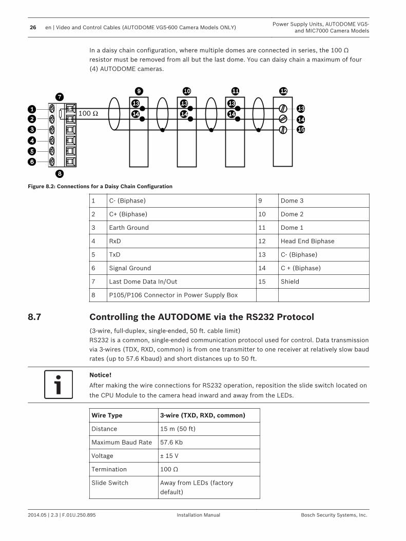
In a daisy chain configuration, where multiple domes are connected in series, the 100 Ωresistor must be removed from all but the last dome. You can daisy chain a maximum of four(4) AUTODOME cameras.
100 Ω
Figure 8.2: Connections for a Daisy Chain Configuration
1 C- (Biphase) 9 Dome 3
2 C+ (Biphase) 10 Dome 2
3 Earth Ground 11 Dome 1
4 RxD 12 Head End Biphase
5 TxD 13 C- (Biphase)
6 Signal Ground 14 C + (Biphase)
7 Last Dome Data In/Out 15 Shield
8 P105/P106 Connector in Power Supply Box
Controlling the AUTODOME via the RS232 Protocol(3-wire, full-duplex, single-ended, 50 ft. cable limit)RS232 is a common, single-ended communication protocol used for control. Data transmissionvia 3-wires (TDX, RXD, common) is from one transmitter to one receiver at relatively slow baudrates (up to 57.6 Kbaud) and short distances up to 50 ft.
Notice!
After making the wire connections for RS232 operation, reposition the slide switch located on
the CPU Module to the camera head inward and away from the LEDs.
Wire Type 3-wire (TXD, RXD, common)
Distance 15 m (50 ft)
Maximum Baud Rate 57.6 Kb
Voltage ± 15 V
Termination 100 Ω
Slide Switch Away from LEDs (factorydefault)
8.7
26 en | Video and Control Cables (AUTODOME VG5-600 Camera Models ONLY)Power Supply Units, AUTODOME VG5-
and MIC7000 Camera Models
2014.05 | 2.3 | F.01U.250.895 Installation Manual Bosch Security Systems, Inc.
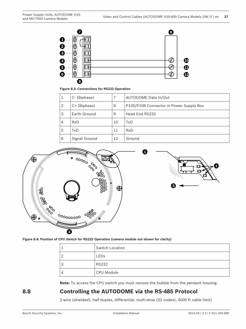
Figure 8.3: Connections for RS232 Operation
1 C- (Biphase) 7 AUTODOME Data In/Out
2 C+ (Biphase) 8 P105/P106 Connector in Power Supply Box
3 Earth Ground 9 Head End RS232
4 RxD 10 TxD
5 TxD 11 RxD
6 Signal Ground 12 Ground
Figure 8.4: Position of CPU Switch for RS232 Operation (camera module not shown for clarity)
1 Switch Location
2 LEDs
3 RS232
4 CPU Module
Note: To access the CPU switch you must remove the bubble from the pendant housing.
Controlling the AUTODOME via the RS-485 Protocol2-wire (shielded), half-duplex, differential, multi-drop (32 nodes), 4000 ft cable limit)
8.8
Power Supply Units, AUTODOME VG5-and MIC7000 Camera Models
Video and Control Cables (AUTODOME VG5-600 Camera Models ONLY) | en 27
Bosch Security Systems, Inc. Installation Manual 2014.05 | 2.3 | F.01U.250.895

RS-485 is capable of controlling a true multi-drop network and is specified for up to 32 driversand 32 receivers on a single 2-wire bus. The AUTODOME camera uses the 2-wire mode,although RS-485 can be connected in a 2- or 4-wire mode.
Notice!
The wire shield must be tied to signal at both ends, if 2-wire twisted pair is used. After
connecting the wires for RS-485 operation, make sure the slide switch on the main board to
the camera head is positioned toward the LEDs (default).
!
Caution!
Bosch recommends that multiple RS-485 connections be arranged as a connected series of
point-to-point (multi-dropped) nodes, as a line or as a bus. It is not recommended to arrange
RS-485 connections as a star, ring, or as a multiple-connected network. Star and ring
topologies may cause signal reflections or excessively low or high termination impedance.
Wire Type 2-wire shielded twisted pair
Distance 1219 m (4000 ft)
Maximum Baud Rate 57.6 kb
Gage 0.511 mm (24 AWG)
Wire Impedance 120 W
Slide Switch Toward LEDs (factory default)
The following figure illustrates the connections for RS-485 connections.
100 Ω
Figure 8.5: Connections for RS485 Operations
1 C- (Biphase) 7 AUTODOME Data In/Out
2 C+ (Biphase) 8 P105/P106 Connector in Power Supply Box
3 Earth Ground 9 Head End RS-485
4 RxD 10 Data +
5 TxD 11 Data -
6 Signal Ground 12 Ground
28 en | Video and Control Cables (AUTODOME VG5-600 Camera Models ONLY)Power Supply Units, AUTODOME VG5-
and MIC7000 Camera Models
2014.05 | 2.3 | F.01U.250.895 Installation Manual Bosch Security Systems, Inc.
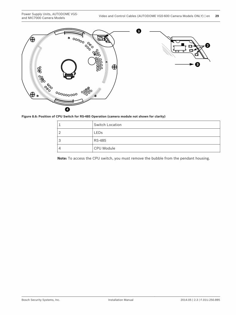
Figure 8.6: Position of CPU Switch for RS-485 Operation (camera module not shown for clarity)
1 Switch Location
2 LEDs
3 RS-485
4 CPU Module
Note: To access the CPU switch, you must remove the bubble from the pendant housing.
Power Supply Units, AUTODOME VG5-and MIC7000 Camera Models
Video and Control Cables (AUTODOME VG5-600 Camera Models ONLY) | en 29
Bosch Security Systems, Inc. Installation Manual 2014.05 | 2.3 | F.01U.250.895
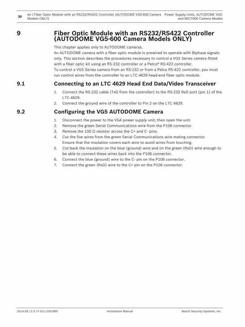
Fiber Optic Module with an RS232/RS422 Controller(AUTODOME VG5-600 Camera Models ONLY)This chapter applies only to AUTODOME cameras.An AUTODOME camera with a fiber optic module is prewired to operate with Biphase signalsonly. This section describes the procedures necessary to control a VG5 Series camera fittedwith a fiber optic kit using an RS-232 controller or a Pelco® RS-422 controller.To control a VG5 Series camera from an RS-232 or from a Pelco RS-422 controller, you mustrun control wires from the controller to an LTC 4629 head-end fiber optic module.
Connecting to an LTC 4629 Head End Data/Video Transceiver1. Connect the RS-232 cable (TxD from the controller) to the RS-232 RxD port (pin 1) of the
LTC 4629.2. Connect the ground wire of the controller to Pin 2 on the LTC 4629.
Configuring the VG5 AUTODOME Camera1. Disconnect the power to the VG4 power supply unit; then open the unit.2. Remove the green Serial Communications wire from the P106 connector.3. Remove the 100 Ω resistor across the C+ and C- pins.4. Cut the five wires from the green Serial Communications wire mating connector.
Ensure that the insulation covers each wire to avoid wires from touching.5. Cut back the insulation on the blue (ground) wire and on the green (RxD) wire enough to
be able to connect these wires back into the P106 connector.6. Connect the blue (ground) wire to the C- pin on the P106 connector.7. Connect the green (RxD) wire to the C+ pin on the P106 connector.
9
9.1
9.2
30en | Fiber Optic Module with an RS232/RS422 Controller (AUTODOME VG5-600 CameraModels ONLY)
Power Supply Units, AUTODOME VG5-and MIC7000 Camera Models
2014.05 | 2.3 | F.01U.250.895 Installation Manual Bosch Security Systems, Inc.
GND T GND GND XD R XD C+ C+ C+ C-
24 VAC
P101
P106 P105
P1
07
XF
10
2
XF
10
3
XF
10
1
5 4
3 2
1
J1
03
J1
03
J1
03
J1
03
J102
J1
01
(LED)
24V NC 24V
GND TXD RXD C+ C- XD
H/A
UX
D
OM
EH
/A
UX
D
OM
EH
/A
UX
D
OM
E
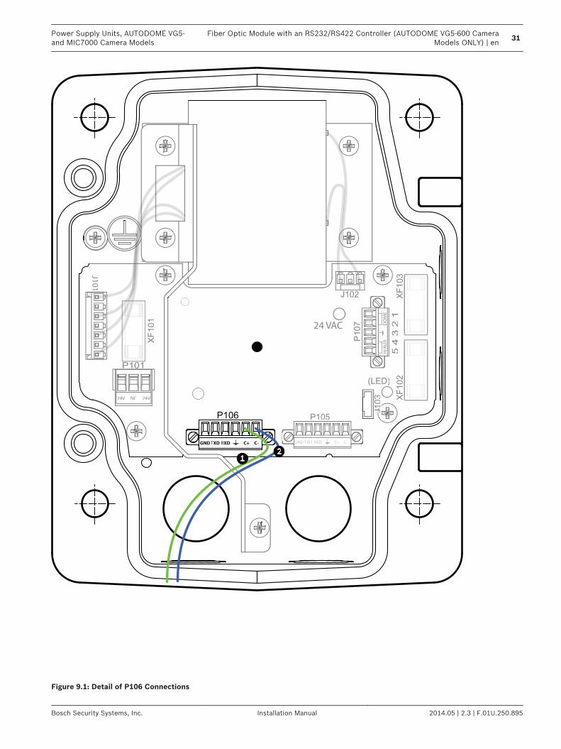
Figure 9.1: Detail of P106 Connections
Power Supply Units, AUTODOME VG5-and MIC7000 Camera Models
Fiber Optic Module with an RS232/RS422 Controller (AUTODOME VG5-600 CameraModels ONLY) | en
31
Bosch Security Systems, Inc. Installation Manual 2014.05 | 2.3 | F.01U.250.895
1 Green RxD wire connected to C+
2 Blue Ground wire connected to C-
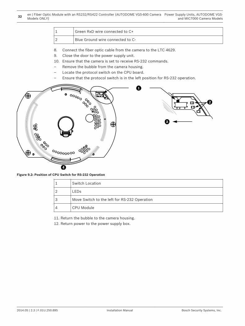
8. Connect the fiber optic cable from the camera to the LTC 4629.9. Close the door to the power supply unit.10. Ensure that the camera is set to receive RS-232 commands.– Remove the bubble from the camera housing.– Locate the protocol switch on the CPU board.– Ensure that the protocol switch is in the left position for RS-232 operation.
Figure 9.2: Position of CPU Switch for RS-232 Operation
1 Switch Location
2 LEDs
3 Move Switch to the left for RS-232 Operation
4 CPU Module
11. Return the bubble to the camera housing.12. Return power to the power supply box.
32en | Fiber Optic Module with an RS232/RS422 Controller (AUTODOME VG5-600 CameraModels ONLY)
Power Supply Units, AUTODOME VG5-and MIC7000 Camera Models
2014.05 | 2.3 | F.01U.250.895 Installation Manual Bosch Security Systems, Inc.

Audio Cables (AUTODOME Cameras ONLY, exceptVG5-600 Models)This chapter applies only to AUTODOME cameras.AUTODOME cameras of the VG5 700 Series, the VG5 800 Series, and the 7000 Series arecapable of receiving line input audio signals and transmitting it over a network. The audiosignal is transmitted one-way and in sync with the video signals.Audio Line Input Specifications
Max. Input Voltage 5.5 Vpp
Impedance 9K Ω
Sample Rate 8 K Hz, 16 Bit, mono
Shield Bare copper braid: 95% coverage
Internal gain level adjustment is available
Wire Specifications
Wire Type Coax3 (recommended)
Distance 10 m (33 ft)
Gage 22 AWG to Biphase connector (P105/P106)
Shield Bare copper braid: 95% coverage
Centerconductor
Stranded bare copper
Notice!
Separate the audio cables from the AC power lines to avoid noise.
Audio Connections1. Remove the 100 Ω termination resistor from the Biphase terminals.2. Connect the audio line level source to the Biphase C+ input terminal.3. Connect the audio signal ground to the Biphase C- input terminal.
The following figure illustrates the connections for audio over an IP network.
10
Power Supply Units, AUTODOME VG5-and MIC7000 Camera Models
Audio Cables (AUTODOME Cameras ONLY, except VG5-600 Models) | en 33
Bosch Security Systems, Inc. Installation Manual 2014.05 | 2.3 | F.01U.250.895
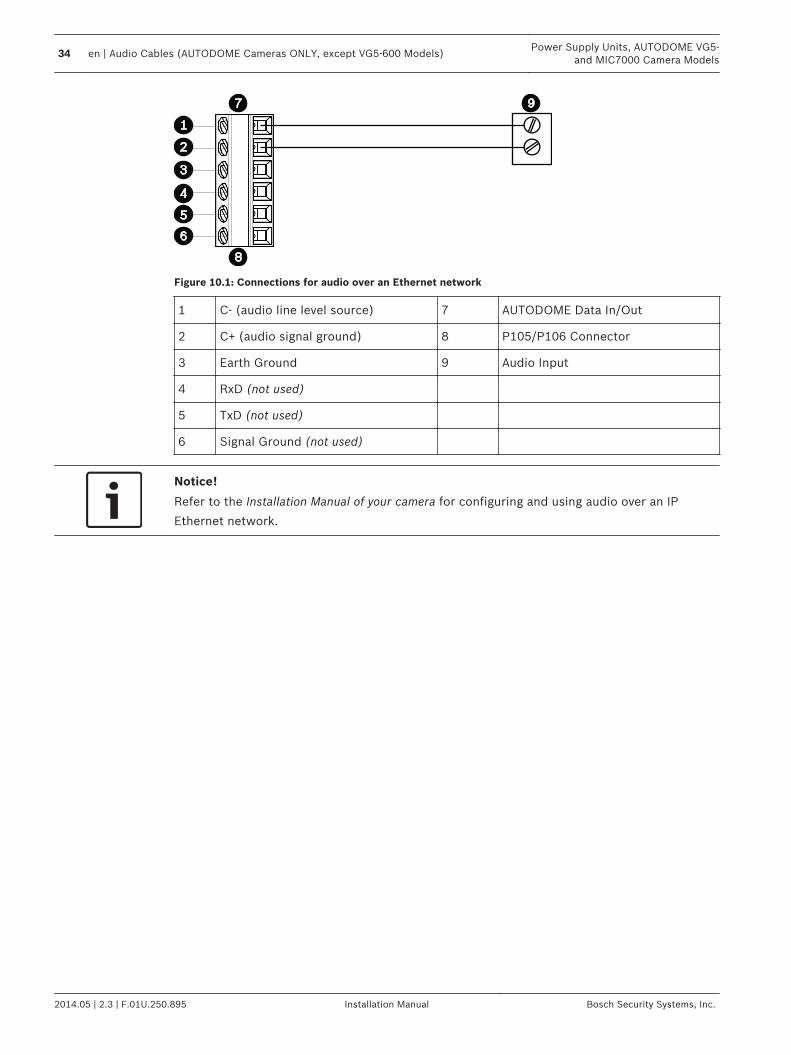
Figure 10.1: Connections for audio over an Ethernet network
1 C- (audio line level source) 7 AUTODOME Data In/Out
2 C+ (audio signal ground) 8 P105/P106 Connector
3 Earth Ground 9 Audio Input
4 RxD (not used)
5 TxD (not used)
6 Signal Ground (not used)
Notice!
Refer to the Installation Manual of your camera for configuring and using audio over an IP
Ethernet network.
34 en | Audio Cables (AUTODOME Cameras ONLY, except VG5-600 Models)Power Supply Units, AUTODOME VG5-
and MIC7000 Camera Models
2014.05 | 2.3 | F.01U.250.895 Installation Manual Bosch Security Systems, Inc.

Bosch Security Systems, Inc.850 Greenfield RoadLancaster, PA, 17601USAwww.boschsecurity.com© Bosch Security Systems, Inc., 2014