power switch cabinet 4-port new generation
TRANSCRIPT

Power SwitchCabinet 4-Port
New Generation
May 2011PSE544-XX
SUPPORT FREE technical support

This product carries the CE mark to indicate compliance with the European Directive on ElectromagneticCompatibility (89/336/EEC). It has been tested to EN55024:1998 and EN55022:1998.
PSE544
The Power Switch is an extension lead that enables you, through an Ethernet 10Base-T network, to switch on oroff the power supply of any electric device.
The built-in mini Web server allows individual control of the four sockets, using a browser.

1
Power Switch CabinetUser's Guide
Chapters
Safety instructions: To be read before use! ______________________________________________________ 21. Description _____________________________________________________________________________ 3
1.1. Diagram ____________________________________________________________________________ 41.2. Package List ________________________________________________________________________ 5
2. Installation _____________________________________________________________________________ 63. Configuration ___________________________________________________________________________ 7
3.1. Configuration through the LAN using the Finder program _____________________________________ 73.2. Configuration through an RS232 Terminal connection ________________________________________ 9
3.2.1. Serial port configuration___________________________________________________________ 93.2.2. Restore to default factory settings __________________________________________________ 103.2.3. Restore to default administrator password ___________________________________________ 10
3.3. Configuration through the LAN using a standard Browser ____________________________________ 113.3.1. General / IP configuration ________________________________________________________ 113.3.2. General / System time ___________________________________________________________ 133.3.3. General / SNMP _______________________________________________________________ 143.3.4. General / Tools ________________________________________________________________ 153.3.5. Settings / Accounts _____________________________________________________________ 16
3.3.5.1 Settings / Accounts _______________________________________________________ 163.3.5.2 Settings / Accounts / Hidden Page account ____________________________________ 18
3.3.6. Settings / Groups _______________________________________________________________ 203.3.7. Settings / Peripherals ___________________________________________________________ 223.3.8. Settings / Rules ________________________________________________________________ 24
3.3.8.1. Settings / Rules - Schedule Rule ____________________________________________ 263.3.8.2. Settings / Rules - Timer Rule _______________________________________________ 283.3.8.3. Settings / Rules - Ping Monitoring Rule _______________________________________ 303.3.8.4. Settings / Rules - Scan Monitoring Rule ______________________________________ 32
3.3.9. Settings / Shutdowns ____________________________________________________________ 343.3.10. Misc / Control Panel ___________________________________________________________ 363.3.11. Misc / Rule Panel ______________________________________________________________ 373.3.12. Misc / Log ___________________________________________________________________ 383.3.13. Misc / Log Settings ____________________________________________________________ 39
4. POWER OUTLET CONTROL _____________________________________________________________ 404.1. via the Internet using a standard browser _________________________________________________ 404.2. through a serial connection ____________________________________________________________ 414.3. through the network using simple commands in your own program_____________________________ 42
5. APPENDIX ____________________________________________________________________________ 455.1. Ping and Scan Methods ______________________________________________________________ 455.2. Technical Data _____________________________________________________________________ 465.3. Commonly used Ports ________________________________________________________________ 465.4. Syslog Messages: Severity Level Definitions ______________________________________________ 47

2
Power Switch Cabinet 4-port New Generation
Safety instructions: To be read before use!
The Power Switch Cabinet devices can only be installed by qualified people with the following installation anduse instructions. The manufacturer disclaims all responsibility in case of a bad use of the Power Switch Cabinetdevices and particularly any use with equipments that may cause personal injury or material damage.
This equipment is designed to be installed on a dedicated circuit that must have a circuit breaker or fuseprotection.
The electrical power socket used to plug the power cord of the Power Switch must be close to the Power SwitchCabinet device and easily accessible.
Check that the power cords, plugs and sockets are in good condition.
The Power Switch Cabinet devices can only be connected to three-wire 230 VAC (50-60Hz) sockets.
Always plug the Power Switch Cabinet devices into properly grounded power sockets (two poles plus ground).
Never exceed 10 Amp total load.
If you have to replace an external fuse of an Power Switch Cabinet device, never use another type of fuse than10A/250V T.
The Power Switch Cabinet devices are intended for indoor use only. Do NOT install them in an area whereexcessive moisture or heat is present.
Always disconnect the power cord of the Power Switch if you want to intervene on the device or on theequipment powered from the Power Switch Cabinet device.
The power outlets of the Power Switch Cabinet devices are not circuit breakers! If you want to intervene onequipment connected to a Power Switch Cabinet device you must disconnect this equipment from the PowerSwitch Cabinet device.
The Power Switch Cabinet devices contain potentially hazardous voltages. Do NOT attempt to disassemblethem.
The Power Switch Cabinet devices contain no user serviceable parts and repairs are to be performed by factorytrained service personnel only.

3
1. DescriptionPower Switch Cabinet is an extension lead that enables you, through an Ethernet 10Base-T network, to switch onor off the power supply of any electric device.
The built-in mini Web server allows individual control of the four sockets, using a browser.Its serial interface can be used to control the power outlets over a Terminal connection (KVM Switch, consoleserver...) or to trigger a soft shutdown of a server with shutdown capabilities. An internal Real Time Clock enablesto trigger scheduled actions and timestamp all events (logs, SNMP traps and Syslog events).
Power Switch PSE544 is more than a simple power strip. It offers IP device monitoring with automatic rebootfunction in case of lock-up.
It supports the HTTP, DHCP, Syslog, SNMP and SNTP protocols.

4
Power Switch Cabinet 4-port New Generation
1.1. Diagram
1 2 3 4 Pwr (LEDs)
1 Red. Status of power outlet 1 (On/Off)2 Red. Status of power outlet 2 (On/Off)3 Red. Status of power outlet 3 (On/Off)4 Red. Status of power outlet 4 (On/Off)Pwr Power Switch is powered
10/100 (RJ45 Connector)Network connection 10/100 Mbits/sec
Link (LED)Off = Network connection not detectedOn = Network connection detectedFlashing = the device is sending or receiving data over this port
100 (LED)Off = 10 Mbits/sec connectionOn = 100 Mbits/sec connection
RS232 (SUB-D 9F Connector)Serial port RS232 with DB-9 female connector
Pinout2 = TxD3 = RxD5 = Gnd
5 LEDs1 - 4 = Status of outlets 1 - 4Pwr = Power
4 power outlets
RJ45 Connector
SUB-D9F ConnectorTerminal connection
Power input câble230 VAC – 10 Amp

5
1.2. Package List
The following items are included:
1 extension lead, 19" rack mountable, 1 serial cable SUB-D 9 points male / female, 1 RJ45 cable, male / male. CD including this user guide and the Power Switch Finder program.
In option: wall mounting kit with 2 metal brackets,4 cage nuts, washer and screws.
The figure shows how to fix the metal brackets

6
Power Switch Cabinet 4-port New Generation
2. Installation
Remark:Make sure that the Power Switch is powered off.
Connection instructions
1. Use a shielded RJ45 network cable to connect your Power Switch to the network.
2. Use appropriated three-wire power cords (two poles plus ground) to connect your electrical devices to thePower Switch unit.
3. Plug the power cable into a grounded socket. The Pwr LED lights on to confirm that power is on.
4. You can now configure the Power Switch by following the indications of the chapter "Configuration of thePower Switch".
7
3. ConfigurationTo use the Power Switch PSE544 on your network, you must first configure its network parameters. Ask yournetwork administrator for the parameters to use.
There are three methods to configure the network parameters of the Power Switch:
3.1. Configuration through the LAN using the Finder program
It is the simplest and fastest configuration method if you use Windows as operating system. It allows to configureyour Power Switch through your local network even if its network parameters are not compatible with those of yourPC.
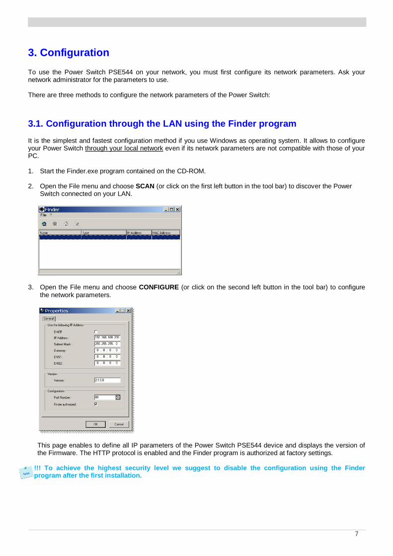
1. Start the Finder.exe program contained on the CD-ROM.
2. Open the File menu and choose SCAN (or click on the first left button in the tool bar) to discover the PowerSwitch connected on your LAN.
3. Open the File menu and choose CONFIGURE (or click on the second left button in the tool bar) to configurethe network parameters.
This page enables to define all IP parameters of the Power Switch PSE544 device and displays the version ofthe Firmware. The HTTP protocol is enabled and the Finder program is authorized at factory settings.
!!! To achieve the highest security level we suggest to disable the configuration using the Finderprogram after the first installation.

8
Power Switch Cabinet 4-port New Generation
DHCP:Check this box is you want to obtain the IP address, the subnet mask and the default gateway for your PowerSwitch via DHCP.Use of DHCP (Dynamic Host Configuration Protocol) requires a DHCP host to be set up on the network.
IP Address:IP address of the Power Switch PSE544, default is 192.168.100.200.Subnet Mask:Subnet Mask of the Power Switch PSE544, default is 255.255.255.0.Gateway:Generally the address of your router, default is blank.DNS 1:Primary DNS (Domain Name Server), default is blank.DNS 2:Secondary DNS, default is blank.
Port Number:Port number: default is 80 (HTTP).
Version:Firmware version of the Power Switch PSE544
Finder authorized:The Network parameters of the Power Switch can be configured through a Local Area Network using the
provided Finder Program. It is a simple and fast configuration method if you use Windows as operating system.!!! The Finder Program is enabled as default value. For security reasons we suggest to disable the Finderprogram after the first configuration.

9
3.2. Configuration through an RS232 Terminal connection
1. Use the provided RS232 cable to connect the Power Switch PSE544 to an available serial port of your PC.
2. Run a Terminal program such as Windows HyperTerminal or the Micro Terminal program on the CD.
3. Configure the appropriate serial port @ 9.600, n, 8, 1 and no flow control. If you use the MicroTerminal programon the CD (folder miscellaneous) you only have to choose the used serial port, this program is alreadyconfigured at 9600,n,8,1.
4. On your computer, press <ENTER> until the menu appears on your screen.
5. Press the “M” on your keyboard and follow the menu to configure the network parameters of your Power SwitchPSE544.
------------------------------------------------------------NETWORK INTERFACE PARAMETERS: IP address on LAN is 192.168.100.200 LAN interface's subnet mask is 255.255.255.0 IP address of default gateway to other networks is 0.0.0.0 IP address of primary DNS server is 0.0.0.0 IP address of secondary DNS server is 0.0.0.0MISCELLANEOUS: HTTP Port is 80 Finder program is enabledHARDWARE PARAMETERS: MAC Address is 00.13.F6.01.3C.80------------------------------------------------------------
Configuration menuSpecial commands (type /? or /Help)/viewlog Displays the log file/initlog Clears the log file/initadminaccount Restores default administrator password/restorefactconf Restores to factory default settings/help /? Displays this help
3.2.1. Serial port configuration
Connector: SUB-D9 female connector
Pin configuration RS232 parametersPin 2 = TxD (transmit data to the PC) Speed: 9600 baudsPin 3 = RxD (receive commands) Parity: NoPin 5 = GnD Format: 8 bits Stop bit: 1 Flow control:no
The serial cable provided with the Power Switch-is a standard straight extension cable with DB9 connectors. Thiscable is intended to connect the serial port of the Power Switch to a serial port of a PC.

10
Power Switch Cabinet 4-port New Generation
3.2.2. Restore to default factory settings
If you want to restore the Power Switch to factory settings, you can reset it to default value using followingprocedure:
1. Use the supplied RS232 cable to connect the Power Switch-to an available serial port of your PC.
2. Run a terminal program such as Windows HyperTerminal or the Micro Terminal program on the CD.
3. Configure the appropriate serial port with the following settings @ 9.600, n, 8, 1 and no flow control. If you usethe Micro Terminal program on the CD (folder miscellaneous) you only have to choose the used serial port, thisprogram is already configured at 9600,n,8,1.
4. On your computer, press <ENTER> until the menu appears on your screen.
5. Type in following command:/restorefactconf (the command MUST be preceded with a slash).
Now you can log in using admin as Login name and password. The login values are case sensitive.
3.2.3. Restore to default administrator password
If you have forgotten your administrator password, you can reset it to default value using following procedure:
1. Use the supplied RS232 cable to connect the Power Switch-to an available serial port of your PC.
2. Run a terminal program such as Windows HyperTerminal .
3. Configure the appropriate serial port with the following settings @ 9.600, n, 8, 1 and no flow control.If you usethe MicroTerminal program on the CD (folder miscellaneous) you only have to choose the used serial port, thisprogram is already configured at 9600,n,8,1.
4. On your computer, press <ENTER> until the menu appears on your screen.
5. Type in following command:/initadminaccount (the command MUST be preceded with a slash).
The system answers:System is restarting...System Started
Now you can log in using admin as Login name and password. The login values are case sensitive.

11
3.3. Configuration through the LAN using a standard Browser
During the first installation, change temporarily the network settings of your PC according to the default networksettings of the Power Switch PSE544.
Factory network settings of the Power Switch PSE544:IP Address: 192.168.100.200 - Port: 80Gateway: 255.255.255.0
1. Open your Web browser and type following IP address:http://192.168.100.200/sysadmin.htm
2. Enter the administrator name and password (default for both = admin)
3. The home page appears, allowing you to configure all settings of your Power Switch PSE544.
3.3.1. General / IP configuration
This page enables you to define all the IP parameters of the Power Switch PSE544.
DHCP Client enabled:Check this box is you want to obtain the IP address, the subnet mask and the default gateway for your PowerSwitch PSE544 via DHCP. Factory default setting for this option is disabled.Use of DHCP (Dynamic Host Configuration Protocol) requires a DHCP host to be set up on the network.IP Address:IP address of the Power Switch PSE544, default is 192.168.100.200.Subnet Mask:Subnet Mask of the Power Switch PSE544, default is 255.255.255.0.Default Gateway:Generally the address of your router, default is blank.Primary DNS Address:Primary DNS (Domain Name Server), default is blankSecondary DNS Address:Secondary DNS, default is blank

12
Power Switch Cabinet 4-port New Generation
Finder Program enabled:The Network parameters of the Power Switch PSE544 can also be configured through a Local Area Network usingthe provided Finder Program. It is a very simple and fast configuration method if you use Windows as operatingsystem.The Finder Program is enabled as default value.!!!For security reasons we suggest to disable the Finder program after the first configuration.
HTTP Port:Port number: default is 80.
LOGOUT:Click "Logout" at the bottom of the page to exit the session without saving changes.DISCARD CHANGES:Click "Discard Changes" at the bottom of the page to discard all the changes you have made on this page.APPLY CHANGES:Click "Apply Changes" at the bottom of the page to save changes.

13
3.3.2. General / System time
The system time of the Power Switch PSE544 is used for synchronizing scheduling actions and to timestampSNMP traps, Syslog information and internal logs. The system time can be set manually with the browser time ofthe connected computer or can be automatically synchronized with one or two NTP timeservers.
Current System Time:This field shows the current system time of the Power Switch PSE544.As the system time is displayed through the browser, a small difference (1 to 2 sec) can appear ascompared to the exact hour. The system time is nevertheless correct.Use Browser Time:If you want to set the system time using the current Browser time of your PC, select this option and click on the"Set System Time" button.Use NTP Server:If you want to set the system time using an NTP timeserver, select this option, choose a refresh interval and enterthe IP address of the timeserver you wish to use in the "Primary" field. The address of a second timeserver can bespecified in the "Secondary" field. The secondary timeserver is optional and is used only if the primary timeserver isnot available.You can enter either the hostname (in that case you must have specified a DNS server on the IPconfiguration page) or the IP address of an NTP server.NTP uses port 123/UDP.Time Zone:Set the time zone corresponding to your location. The system clock will subsequently show local time. Withoutsetting this, the system clock will show UTC/GMT time. Setting a time zone is only relevant if you are synchronizingwith an NTP server.Daylight Saving Time:If you want to set Daylight Saving dates, check this box and specify the date you want to use.
LOGOUT:Click "Logout" at the bottom of the page to exit the session without saving changes.DISCARD CHANGES:Click "Discard Changes" at the bottom of the page to discard all the changes you have made on this page.APPLY CHANGES:Click "Apply Changes" at the bottom of the page to save changes.

14
Power Switch Cabinet 4-port New Generation
3.3.3. General / SNMP
The Power Switch PSE544 provides a built-in SNMP (Simple Network Management Protocol) agent, which enablesyou to manage the Power Switch PSE544 through SNMP-based network management systems. The Power SwitchPSE544 MIB file enables to remotely read out the status of all power outlets and the values of all sensors(temperature, humidity, ambient light). It also enables to control individually all power outlets and all groups ofpower outlets. The MIB file is stored on the Power Switch PSE544 and can be downloaded from the General /Tools Page.
SNMP enabled:Check this box if you want to enable the SNMP protocol.Contact:In this field, enter the name you want to give to the Contact field. The name can be from 1 to 64 characters long,and can contain alphanumeric characters. Default name is "contact".Name:In this field, enter the name you want to give to the Name field. The name can be from 1 to 64 characters long, andcan contain alphanumeric characters. Default name is "name".Location:In this field, enter the name you want to give to the Location field. The name can be from 1 to 64 characters long,and can contain alphanumeric characters. Default name is "location".Read Community:In this field, enter the name you want to give to the Read Community field. The name can be from 1 to 64characters long, and can contain alphanumeric characters. Default name is "public".Write Community:Check this box if you want to be able to control the power outlets through a MIB browser. In the following field,enter the name you want to give to the Write Community. The name can be from 1 to 64 characters long, and cancontain alphanumeric characters. Default name is "private".Trap Community:Check this box if you want to configure the Power Switch PSE544 SNMP agent to send traps to a community. Inthe following field, enter the name you want to give to the Trap Community. The name can be from 1 to 64characters long, and can contain alphanumeric characters. Default name is "trap".Trap Destination 1:Check this box and enter the primary SNMP Server address the traps will be sent to.Trap Destination 2:Check this box and enter the secondary SNMP Server address the traps will be sent to.
LOGOUT:Click "Logout" at the bottom of the page to exit the session without saving changes.DISCARD CHANGES:Click "Discard Changes" at the bottom of the page to discard all the changes you have made on this page.APPLY CHANGES:Click "Apply Changes" at the bottom of the page to save changes.

15
3.3.4. General / Tools
This page enables you to:- download and save the current settings of your Power Switch PSE544 on your PC,- upload an existing configuration file to your Power Switch PSE544,- restore the factory settings,- download the Power Switch PSE544 MIB file on your PC.
Save:Click this button to save the current system settings onto your local hard drive.Load:Click this button and select a settings file you want to download to the Power Switch PSE544.Restore:Click this button if you want to restore the factory default settings.Save MIB:Click this button if you want to download the Power Switch PSE544 MIB file onto your local hard drive.
LOGOUT:Click "Logout" at the bottom of the page to exit the session without saving changes.

16
Power Switch Cabinet 4-port New Generation
3.3.5. Settings / Accounts
3.3.5.1 Settings / Accounts
This page is used to create, activate, deactivate, modify and delete up to 40 accounts.
- To activate or deactivate an account, check or uncheck the corresponding checkbox.- To modify an account, click on "Edit" next to the corresponding account.- To delete an existing account, click on "Delete" next to the corresponding account.- To create an account, click on "Add a New Account" on the right side of the page. A new page appears, allowing you to set all the parameters of the account.
User Name:In this field, enter the name you want to give to the user. The name can be from 1 to 32 characters long, and cancontain alphanumeric characters.Do not use quotes or special characters in labels!Password:In this field, enter the password you want to give to the user. The password can be from 4 to 32 characters long,and can contain alphanumeric characters.Confirm Password:In this field, enter the password again.
IP Address Control:Check this checkbox and specify an IP address or a range of IP address if you want to restrict the access of thisaccount.
Groups:This field is used to add or remove groups to the current account.To add Groups to the current account, press the Ctrl key and click on the displayed Groups. The selected Groupsare marked dark blue and their IDs are listed at the right side of the Groups field.This field appears only if you have already created at least one group (Settings/Groups Tab).

17
Device:In this drop-down list, choose a device from which you want to add Inputs or Outputs to the current account.Inputs/Outputs:This field is used to add/remove Inputs or Outputs to/from the current account.To add Inputs or Outputs to the current account, press the Ctrl key and click on the Inputs/Outputs of the deviceselected in the previous field. The selected Inputs/Outputs are marked dark blue and their IDs are listed at the rightside of the Input/Output field.
LOGOUT:Click "Logout" at the bottom of the page to exit the session without saving changes.DISCARD CHANGES:Click "Discard Changes" at the bottom of the page to discard all the changes you have made on this page.APPLY CHANGES:Click "Apply Changes" at the bottom of the page to save changes.

18
Power Switch Cabinet 4-port New Generation
3.3.5.2 Settings / Accounts / Hidden Page account
This account is intended for developers who want to implement the power outlet control in own programs. Ifactivated, they can access to a special page named hidden.htm and control individually the power outlets usingsimple commands.
- To activate or deactivate this account, check or uncheck the corresponding checkbox.- To modify the Hidden page account, click on "Edit" next to the corresponding account. A new page appears, allowing you to set all the parameters of the account.
ActivatedThis check box must be checked to activate the Hidden Page Account. It enables to deactivate temporarily thisaccount while keeping all its settings for a later use. The Hidden Page Account cannot be deleted.User NameIn this field, enter the name you want to give to the Hidden Page Account.The user name can be up to 32 characters long and contain alphanumeric characters.Do not use quotes or special characters in labels!PasswordIn this field, enter the password you want to give to the Hidden Page Account.The password can be up to 32 characters long and contain alphanumeric characters.Confirm PasswordIn this field, enter the password again for confirmation.IP Address ControlNetwork security can be increased by IP address filtering. Check this checkbox and specify an IP address or arange of IP addresses which has the right to access to the Hidden Page Account.
GroupsThis field appears only if at least one group has already been created. To create a group, go to theSettings/Groups Page.- To add an existing group of Power Outlets to the current account, select the group you want to add in the left fieldand click on the Arrow button, the group will then appear in the right field.- To remove a Group from the current account, select the group you want to remove in the right field and click onthe Arrow button, the group will then appear in the left field.Each group is clearly identified by its own ID (G1, G2, G3...) followed by the name given during theconfiguration. If the symbol "!" appears between brackets behind the ID Code that means that the Group isnot activated. To activate it, go to the "Settings/Groups" page.

19
DeviceIn this drop-down list, choose the device from which one you want to add Inputs or Outputs to the current account.Inputs/Outputs- This field is used to add/remove Inputs or Outputs to/from the current account.- To add an Input or Output to the current account, select the Input / Output you want to add in the left field and
click on the Arrow button, the selected Input / Output will then appear in the right field.- To remove an Input or Output from the current account, select the Input / Output you want to remove in the right
field and click on the Arrow button, the selected Input / Output will then appear in the left field.
Accessing to the Hidden Page AccountTo be able to access to the Hidden Page, you must have configured the Hidden Page Account and activated it. Forthe first tests, simply check the Activated check box, start your browser and type into your browser's address barthe IP address of your power switch followed by the name of the hidden page.
Example: if the IP address of your Power Switch is 192.168.100.200, type in:http://192.168.100.201/hidden.htm followed by <ENTER>.
Your Web browser will now display:Hidden PageDateVersion
Controlling Power OutletsOnly Power Outlets which have been selected can be controlled over the Hidden Page. To select Power Outlets,go to the "Settings/Accounts" page and edit the Hidden Page Account. In the Inputs/Outputs field, selected thePower Outlets you want to control and click on the Arrow button next to the Inputs/Outputs field. The selectedPower outlets appear in the right field, click on Apply Change to validate the configuration.
Example: if you have selected all 4 power Outlets and the IP address of your Power Switch is 192.168.100.200,type in:http://192.168.100.201/hidden.htm followed by <ENTER>.
Your Web browser will now display:Hidden PageDateVersionM0:O1=OnM0:O2=OnM0:O3=OnM0:O4=On
Each Power Outlet support individually 3 commands: On, Off and Restart using following syntax:M0:Ox=[ON], [OFF], [RESTART]
M0: ID of your Power SwitchOx: Outlet number of your Power SwitchON: ON commandOFF: OFF commandRESTART: Restart command
The first command must be preceded by a "?"Commands can be concatenated using the character "&"Commands can be specified in upper case, lower case or mixed case
Example: if you want to switch to OFF the Power Outlet #1 and 3, type in:http://192.168.100.201/hidden.htm?M0:O1=OFF&M0:O3=OFF
Your Web browser will now display:Hidden PageDateVersionM0:O1=OffM0:O2=OnM0:O3=Off

20
Power Switch Cabinet 4-port New Generation
M0:O4=On
3.3.6. Settings / Groups
This page is used to create, modify and delete groups of power outlets which can be controlled by the PowerSwitch PSE544. This functionality is particularly useful if you have to control the power supply of devices usingredundant power supplies. You can create groups including several power outlets distributed on several PowerSwitch 8XS devices.
- To delete an existing group, click on "Delete" of the corresponding device.- To add or remove power outlets to/from an existing group, click on "Edit" of the corresponding device.- To deactivate a Group, uncheck the box "Activated" of the corresponding group.- To add a new group, click on "Add a New Group" on the right side of the page. A new page appears, allowing you to set all parameters of the group.
ActivatedThis check box must be checked to activate the group. It enables to deactivate temporarily a group of Poweroutlets while keeping all its settings for a later use.Group Id:The Power Switch PSE544 automatically creates an ID Code to clearly identify each group of power outlets. All theID Codes used to identify groups start with the letter "G".Group Name:In this field, enter the name you want to give to the selected group. The name can be from 1 to 32 characters long,and can contain alphanumeric characters.Do not use quotes or special characters in labels!
Device:In this drop-down list, choose an Power Switch from which you want to add power outlets to the selected group.Power Outlets:This field is used to add and remove power outlets to/from the group.To add power outlets to the group, press the Ctrl key and click on the power outlets of the Power Switch selected inthe field above. The selected power outlets are marked dark blue and their names are listed at the right of the field"Power Outlets".To remove a power outlet from the group, press the Ctrl key and click on the power outlet you wish to remove.
LOGOUT:Click "Logout" at the bottom of the page to exit the session without saving changes.DISCARD CHANGES:Click "Discard Changes" at the bottom of the page to discard all the changes you have made on thispage.APPLY CHANGES:

21
Click "Apply Changes" at the bottom of the page to save changes.
22
Power Switch Cabinet 4-port New Generation
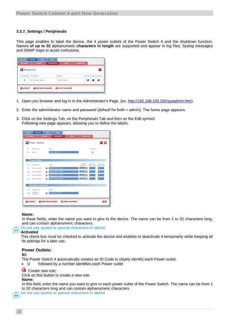
3.3.7. Settings / Peripherals
This page enables to label the device, the 4 power outlets of the Power Switch 4 and the shutdown function.Names of up to 32 alphanumeric characters in length are supported and appear in log files, Syslog messagesand SNMP traps to avoid confusions.
1. Open you browser and log in to the Administrator's Page, (ex. http://192.168.100.200/sysadmin.htm).
2. Enter the administrator name and password (default for both = admin). The home page appears.
3. Click on the Settings Tab, on the Peripherals Tab and then on the Edit symbol.Following new page appears, allowing you to define the labels.
Name:In these fields, enter the name you want to give to the device. The name can be from 1 to 32 characters long,and can contain alphanumeric characters.Do not use quotes or special characters in labels!ActivatedThis check box must be checked to activate the device and enables to deactivate it temporarily while keeping allits settings for a later use.
Power Outlets:ID:The Power Switch 4 automatically creates an ID Code to clearly identify each Power outlet.
O followed by a number identifies each Power outlet
Create new rule:Click on this button to create a new rule.Name:In this field, enter the name you want to give to each power outlet of the Power Switch. The name can be from 1to 32 characters long and can contain alphanumeric characters.Do not use quotes or special characters in labels!

23
Default Power-Up:In the drop-down lists, choose for each power outlet the default status to apply after power-up.You can choose between:- "On" if you want the corresponding power outlet to be always switched On after power-up.- "Off" if you want the corresponding power outlet to be always switched Off after power-up.- "Last Status" if you want that the corresponding power outlet takes again the state it was in before power failure.
Power up delay:In this field, enter the power up delay you want to define for each power outlet. Power up delay means the delaybefore the power outlet will take the defined status after power up. The delay can be set between 1 and 65535seconds, the value 0 means that no delay has to be applied after power up.Function delay:In this field, enter the delay you want to define before the execution of a function (for example Restart functionof an outlet).
Shutdowns FunctionsID:The Power Switch 4 automatically creates an ID Code to clearly identify the Shutdown Function.
SD1 identifies the Shutdown Function 1.
Create a new Shutdown Association:Click on this button to create a new Shutdown Association.Name:In this field, enter the name you want to give to the Shutdown function. The name can be from 1 to 32characters long and can contain alphanumeric characters.Do not use quotes or special characters in labels!
Click "Apply Changes" at the bottom of the page to save changes.LOGOUT:Click "Logout" at the bottom of the page to exit the session without saving changes.DISCARD CHANGES:Click "Discard Changes" at the bottom of the page to discard all the changes you have made on this page.APPLY CHANGES:Click "Apply Changes" at the bottom of the page to save changes.

24
Power Switch Cabinet 4-port New Generation
3.3.8. Settings / Rules
Rules are used to control actions according to a specific event. For example, you can define a rule to switch apower outlet OFF and send an alert message using different methods like SNMP or Syslog when a temperature,humidity, ambient light or current exceeds a predefined value or when a contact is open.
- To remove an existing rule, click on "Delete" of the corresponding rule.- To modify a rule, click on "Edit" of the corresponding rule.
This page is used to create, modify and delete rules.- To add a new rule, click on "Add a New Rule" on the right side of the page. A new page appears, allowing you to set all the parameters of the rule.

25
A total of 32 rules can be created and there are 4 different types of rules:
1. Schedule Rule:This rule is used to trigger user-specified actions according to a defined time table.This rule can be used to:- execute once defined actions at specified time and weekday(s). In this case you must only specify the start time
and the weekday(s),- execute repeatedly defined actions during a given time. In this case you must specify the start time, the interval
on which the rule has to be repeated and the end time.Example:- The rule could be used to restart a power outlet (or a group of power outlets) at regular interval during a given
time.
2. Timer Rule:This rule can be used to trigger user-specified actions according to a defined time table.This rule can be used to switch On or Off a power outlet (or a group of power outlets) at specified time andweekday(s) for a specified time. You must define the start time, the weekday(s) and the stop time.Example:- The rule could be used to switch On a device every Monday and Friday from 8:00 AM (Start Time) and switch itautomatically off every Monday and Friday at 05:00 PM (Stop Time)
3. Ping Monitoring Rule:This rule is used to control actions according to the response to a Ping command.This rule can be used to check if a computer or any IP device is connected to the network. If the host doesn't reply,the Power Switch PSE544 can automatically restart the powered device.
4. Scan Monitoring Rule:This rule is used to control actions according to the response to a Scan command.This rule can be used to check if a specific protocol is available on a. If the connection is not possible, PowerSwitch PSE544 can automatically restart the powered device.

26
Power Switch Cabinet 4-port New Generation
3.3.8.1. Settings / Rules - Schedule Rule
This rule can be used to trigger user-specified actions according to a defined time table. The schedule rule isweekday based and the administrator can declare, for each weekday, a start time, an end time and after what timethe rule should be repeated.
The schedule rule can also be used to send status information on specified weekdays at regular interval.
ActivatedThis check box must be checked to activate the Rule and enables to deactivate temporarily a rule while keeping allits settings for a later use.Rule ID:The Power Switch PSE544 automatically creates an ID Code to clearly identify each rule. All the ID Codes used toidentify rules start with the letter "R" followed by a number from 1 to 32. If you delete a rule in the middle of the Rulelist, the number of this rule will only be used again if no other rule is available.Rule Name:In this field, enter the name you want to give to the rule. The name can be from 1 to 32 characters long, and cancontain alphanumeric characters.Do not use quotes or special characters in labels!Rule Color:In this field, select one of the 48 standard colours you want to use to highlight the rule when executed. To use owncolours, just type in the Hex value of the colour you want. The Rule highlighting allows to quickly identify thetriggered rule when displayed in the Rule Panel page or in a special user's page.Rule Type:In this drop-down list, choose Schedule Rule then configure the event and the actions to perform.
Configuring the Event
Schedule Action:Here you can define the time when the rule has to be executed. In the Drop-Down lists choose the time and below,check one or more day boxes.Start TimeDefines what time the rule starts.Repeat TimeDefines the time period in which the rule repeats.Repeat Time cannot be set to zero.

27
Stop TimeDefines what time the rule ends.- End Time must be greater than or equal to Start Time.- If the rule has to be executed only once at the selected weekday, enter the same value for Start Time and
End Time.- If the rule has to be executed 24 hours at the selected weekday, Start Time must be 1 minute later than
EndTime.Applicable weekdayDefines which day(s) the rule has to be executed.
Type of Action
For the Event defined above, you can choose and configure following actions:
Set Group:This type of action appears and can be configured only if you have already created at least one group(Settings/Groups Tab).Check this box and in the corresponding drop-down list choose the power outlet group the rule will apply to. In thenext corresponding drop-down list, choose the action to execute.Each power outlet group can be switched On/Off and restarted. If you choose "restart" you will also be able todefine a restart delay between 0 and 65535 seconds.- If you choose 0 second, the delay will be the delay defined in the Power Switch power outlets settings.- If you choose a delay different from 0, the delay will replace the delay defined in the Power Switch power outlets
settings.Set Power Outlet:Check this box and in the corresponding drop-down list, choose the power outlet the rule will apply to. In the nextcorresponding drop-down list, choose the action to execute. Each power outlet can be switched On/Off andrestarted. If you choose "restart" you will also be able to define a restart delay between 0 and 65535 seconds.- If you choose 0 second, the delay will be the delay defined in the Power Switch power outlets settings.- If you choose a delay different from 0, the delay will replace the delay defined in the Power Switch power outlets settings.Send Syslog Message:This type of action can be configured only if you have already created at least one destination SyslogServer (Misc/Log Settings Tab).Check this box if you want to send a message to a Syslog server. In the following drop-down lists choose thefacility and the severity of the message to send. The address of the Syslog server has to be defined in the "LogSettings Page".Send Trap Message:This type of action can be configured only if you have already specified at least a destination SNMP Server(General/SNMP Tab).Check this/these box(es) and specify one or two SNMP addresses in the corresponding field if you want to sendSNMP messages to one or two SNMP Servers.Syslog / Trap Message:This field can be used only if you have already specified at least one destination Syslog Server (Misc/LogSettings Page) or one destination SNMP Server (General/SNMP Page.Up to 255 characters may be entered in this free text field. The text will appear in the Syslog and the Trap.The message can be completed with the status of an input (a power supply or door contact for example) or thevalue of a sensor (a temperature sensor for example). For this, simply enter, between two percent characters, theID of the corresponding input device (for details see § 5.1 Sending status and values using rules).
LOGOUT:Click "Logout" at the bottom of the page to exit the session without saving changes.DISCARD CHANGES:Click "Discard Changes" at the bottom of the page to discard all the changes you have made on this page.APPLY CHANGES:Click "Apply Changes" at the bottom of the page to save changes.

28
Power Switch Cabinet 4-port New Generation
3.3.8.2. Settings / Rules - Timer Rule
This rule can be used to trigger some actions according to a defined time table.For instance, you could create a rule to switch OFF a Power Outlet every Friday at 6 PM and create another rule toswitch the Power Outlets ON again every Monday at 8 AM.
ActivatedThis check box must be checked to activate the rule. It enables to deactivate temporarily a rule while keeping all itssettings for a later use.Rule IDThe Power Switch automatically creates an ID Code to clearly identify each rule. These codes start with the letter"R" followed by a number.Rule NameIn this field, enter the name you want to give to the rule. The name can be from 1 to 32 characters long, and cancontain alphanumeric characters.Do not use quotes or special characters in labels!Rule Color:In this field, select one of the 48 standard colours you want to use to highlight the rule when executed. To use owncolours, just type in the Hex value of the colour you want. The Rule highlighting allows to quickly identify thetriggered rule when displayed in the Rule Panel page or in a special user's page.Rule TypeIn this Drop-Down list, choose Schedule Rule.Rules are used to control actions according to a specific event. To create a rule, you will first have to configure thechosen event and then to choose the actions to perform.
Configuring the Event
Timer ActionStart TimeDefines what time the rule starts.Stop TimeDefines what time the rule ends.Applicable weekdayDefines which day(s) the rule has to be executed.

29
Type of Action
For the Event defined above, you can choose and configure following actions:
Set Group:This type of action appears and can be configured only if you have already created at least one group(Settings/Groups Tab).Check this box and in the corresponding drop-down list choose the power outlet group the rule will apply to. In thenext corresponding drop-down list, choose the action to execute.Each power outlet group can be switched On/Off and restarted. If you choose "restart" you will also be able todefine a restart delay between 0 and 65535 seconds.- If you choose 0 second, the delay will be the delay defined in the Power Switch power outlets settings.- If you choose a delay different from 0, the delay will replace the delay defined in the Power Switch power outlets
settings.Set Power Outlet:Check this box and in the corresponding drop-down list, choose the power outlet the rule will apply to. In the nextcorresponding drop-down list, choose the action to execute. Each power outlet can be switched On/Off andrestarted. If you choose "restart" you will also be able to define a restart delay between 0 and 65535 seconds.- If you choose 0 second, the delay will be the delay defined in the Power Switch power outlets settings.- If you choose a delay different from 0, the delay will replace the delay defined in the Power Switch power outlets settings.
LOGOUT:Click "Logout" at the bottom of the page to exit the session without saving changes.DISCARD CHANGES:Click "Discard Changes" at the bottom of the page to discard all the changes you have made on this page.APPLY CHANGES:Click "Apply Changes" at the bottom of the page to save changes.

30
Power Switch Cabinet 4-port New Generation
3.3.8.3. Settings / Rules - Ping Monitoring Rule
This rule can be used to check if a computer or any IP device is connected to the network. It sends ping packetsand listens for replies from the specific host. If the host doesn't reply, the Power Switch PSE544 can automaticallyswitch the powered device off and after a specified delay, switch it again on (for details see Ping & Scan Method).
ActivatedThis check box must be checked to activate the Rule and enables to deactivate temporarily a rule while keeping allits settings for a later use.Rule ID:The Power Switch PSE544 automatically creates an ID Code to clearly identify each rule. All the ID Codes used toidentify rules start with the letter "R" followed by a number from 1 to 32. If you delete a rule in themiddle of the Rule list, the number of this rule will only be used again if no other rule is available.Rule Name:In this field, enter the name you want to give to the rule. The name can be from 1 to 32 characters long, and cancontain alphanumeric characters.Do not use quotes or special characters in labels!Rule Color:In this field, select one of the 48 standard colours you want to use to highlight the rule when executed. To use owncolours, just type in the Hex value of the colour you want. The Rule highlighting allows to quickly identify thetriggered rule when displayed in the Rule Panel page or in a special users page.Rule Type:In this drop-down list, choose Ping Monitoring Rule then configure the event and the actions to perform.
Configuring the Event
Monitored device address:In this field enter the IP address of the IP device that you want to monitor using the Ping command.Wait Time for Answer:In this field, define the delay in seconds for the Answer Timeout.The delay can be set between 1 and 10 seconds.Interval between Requests:In this field, define the delay in seconds between ping commands sent to the IP device to monitor.The delay can set between 30 and 65535 seconds.Number of unsuccessful Requests before Action:In this field, define the number of Ping commands to be sent to the IP device before executing the actions.The number can be set between 1 and 65535 seconds.
Delay before First Request after Action:In this field, define the time in seconds before restarting the monitoring after the reboot action.The delay can be set between 30 and 65535 seconds.Maximum Number of ActionsIn this field, define the maximum number of actions.

31
The number can be set between 0 and 255.Type of Actions:
For the Event defined above, you can choose and configure following actions:
Set Group:This type of action appears and can be configured only if you have already created at least one group(Settings/Groups Tab).Check this box and in the corresponding drop-down list choose the power outlet group the rule will apply to. In thenext corresponding drop-down list, choose the action to execute.Each power outlet group can be switched On/Off and restarted. If you choose "restart" you will also be able todefine a restart delay between 0 and 65535 seconds.- If you choose 0 second for the delay, the delay will be the delay defined in the power outlets settings.- If you choose a delay different from 0, it will replace the delay defined in the power outlets settings.Set Power Outlet:Check this box and in the corresponding drop-down list, choose the power outlet the rule will apply to. In the nextcorresponding drop-down list, choose the action to execute. Each power outlet can be switched On/Off andrestarted. If you choose "restart" you will also be able to define a restart delay between 0 and 65535 seconds.- If you choose 0 second, the delay will be the delay defined in the Power Switch power outlets settings.- If you choose a delay different from 0, the delay will replace the delay defined in the Power Switch power outlets settings.Send Syslog Message:This type of action appears and can be configured only if you have already created at least one destinationSyslog Server (Misc/Log Settings Tab).Check this box if you want to send a message to a Syslog server. In the following drop-down lists choose thefacility and the severity of the message to send. The address of the Syslog server has to be defined in the "LogSettings Page".Send Trap MessageThis type of action appears and can be configured only if you have already specified at least a destinationSNMP Server (General/SNMP Tab).Check this/these box(es) and specify one or two SNMP addresses in the corresponding field if you want to sendSNMP messages to one or two SNMP Servers.Syslog / Trap MessageThis field can be used only if you have already configured at least one destination Syslog Server (Misc/LogSettings Page).Up to 255 characters may be entered in this free text field. The text will appear in the Syslog and the Trap.
LOGOUT:Click "Logout" at the bottom of the page to exit the session without saving changes.DISCARD CHANGES:Click "Discard Changes" at the bottom of the page to discard all the changes you have made on this page.APPLY CHANGES:Click "Apply Changes" at the bottom of the page to save changes.

32
Power Switch Cabinet 4-port New Generation
3.3.8.4. Settings / Rules - Scan Monitoring Rule
This rule can be used to check if a specific protocol is available on a server (for example HTTP, FTP, Telnet,POP...). If the connection is possible, Power Switch PSE544 knows that a server program is running there. If theconnection is not possible, Power Switch PSE544 can automatically switch the powered device off and, after aspecified delay, switch it again on (for details see Ping & Scan Method).
ActivatedThis check box must be checked to activate the Rule and enables to deactivate temporarily a rule while keeping allits settings for a later use.Rule ID:The Power Switch PSE544 automatically creates an ID Code to clearly identify each rule. All the ID Codes used toidentify rules start with the letter "R" followed by a number from 1 to 32. If you delete a rule in themiddle of the Rule list, the number of this rule will only be used again if no other rule is available.Rule Name:In this field, enter the name you want to give to the rule. The name can be from 1 to 32 characters long, and cancontain alphanumeric characters.Do not use quotes or special characters in labels!Rule Color:In this field, select one of the 48 standard colours you want to use to highlight the rule when executed. To use owncolours, just type in the Hex value of the colour you want. The Rule highlighting allows to quickly identify thetriggered rule when displayed in the Rule Panel page or in a special users page.Rule Type:In this drop-down list, choose Scan Monitoring Rule then configure the event and the actions to perform.
Configuring the Event
Monitored Device Address:In this field, enter the IP address of the IP device that you want to monitor using the Scan command. In the "Port toscan" field, enter the port number you want to monitor.The value can be set between 1 and 65535.Wait Time for Answer:In this field, define the delay in seconds for the Answer Timeout.The delay can be set between 1 and 10 seconds.Interval between Requests:In this field, define the delay between the scan commands sent to the IP device. The delay can be set between 30and 65535 seconds.Number of unsuccessful Requests before Action:In this field, define the number of Port scanning commands to be sent to the IP device before executing the actions.The number can be set between 1 and 65535 seconds.

33
Delay before First Request after Action:In this field, define the time in seconds before restarting the monitoring after the reboot action.The delay can be set between 30 and 65535 seconds.Maximum Number of ActionsIn this field, define the maximum number of actions.The number can be set between 0 and 255.
Configuring the ActionsFor the Event defined above, you can choose and configure following actions:Set GroupThis type of action appears and can be configured only if you have already created at least one group(Settings/Groups Tab).Check this box and in the corresponding drop-down list choose the power outlet group the rule will apply to. In thenext corresponding drop-down list, choose the action to execute.Each power outlet group can be switched On/Off and restarted. If you choose "restart" you will also be able todefine a restart delay between 0 and 65535 seconds.- If you choose 0 second, the delay will be the delay defined in the power outlets settings.- If you choose a delay different from 0, the delay will replace the delay defined in the power outlets settings.Set Power Outlet:Check this box and in the corresponding drop-down list, choose the power outlet the rule will apply to. In the nextcorresponding drop-down list, choose the action to execute. Each power outlet can be switched On/Off andrestarted. If you choose "restart" you will also be able to define a restart delay between 0 and 65535 seconds.- If you choose 0 second, the delay will be the delay defined in the Power Switch power outlets settings.- If you choose a delay different from 0, the delay will replace the delay defined in the Power Switch power outlets settings.Send Syslog Message:This type of action can be configured only if you have already created at least one destination SyslogServer (Misc/Log Settings Tab).Check this box if you want to send a message to a Syslog server. In the following drop-down lists choose thefacility and the severity of the message to send. The address of the Syslog server has to be defined in the "LogSettings Page".Send Trap Message:This type of action can be configured only if you have already specified at least a destination SNMP Server(General/SNMP Tab).Check this/these box(es) and specify one or two SNMP addresses in the corresponding field if you want to sendSNMP messages to one or two SNMP Servers.Syslog / Trap Message:This field can only be used if you have already specified at least one destination Syslog Server (Misc/LogSettings Page) or one destination SNMP Server (General/SNMP Page).Up to 255 characters may be entered in this free text field. The text will appear in the Syslog and the Trap.
LOGOUT:Click "Logout" at the bottom of the page to exit the session without saving changes.DISCARD CHANGES:Click "Discard Changes" at the bottom of the page to discard all the changes you have made on this page.APPLY CHANGES:Click "Apply Changes" at the bottom of the page to save changes.

34
Power Switch Cabinet 4-port New Generation
3.3.9. Settings / Shutdowns
This power switch supports shutdown facilities of 1 server via its Serial RS232 interface.
- To remove an existing Shutdown association, click on "Delete" of the corresponding rule.- To modify a Shutdown rule, click on "Edit" of the corresponding rule.
This page is used to create, modify and delete a Shutdown Association.Click on "Add a New Shutdown" on the right side of the page. A new page appears, allowing you to set all the parameters of the rule.
ActivatedThis check box must be checked to activate the Shutdown Rule and enables to deactivate temporarily a rule whilekeeping all its settings for a later use.
Shutdown Association IDThe Power Switch automatically creates ID codes to clearly identify each rule. The codes used to indentifyShutdown Rules start with the letters "SDA" followed by a number.Shutdown Association NameIn this field, enter the name you want to give to the rule. The name can be from 1 to 32 characters long, and cancontain alphanumeric characters.Do not use quotes or special characters in labels!Delay after Shutdown before continueIn this field, specify a delay after which the associated power outlet will be switch to off.
Shutdown DeviceIn this Drop-Down list, choose the device which will be used to trigger the Shutdown action. If the Power Switch isused as stand-alone unit, this Drop-Down list will only show the Power Switch itself.
Shutdown OutputsIn this field, choose the output which will be used to trigger the Shutdown.- To select an output, select the output you want to add in the left field and click on the Arrow button, the output will then appear in the right field.- To remove the selected output, select this output in the right field and click on the Arrow button, the output will then appear in the left field.

35
Group:This type of action appears and can be configured only if you have already created at least one group(Settings/Groups Tab).In this field, choose the group of power outlets which will be used for the Shutdown rule.- To select a group, select the output you want to add in the left field and click on the Arrow button, the output willthen appear in the right field.- To remove the group displayed in the right field, select this group in the right field and click on the Arrow button,the group will then appear in the left field.DeviceIn this Drop-Down list, choose the device of which the power outlet will be used to trigger the Shutdown action. Ifthe Power Switch is used as stand-alone unit, this Drop-Down list will only show the Power Switch itself.Power OutletsIn this field, choose the Power Outlet will be used to trigger the Shutdown.- To select a Power Outlet, select the Power outlet you want to add in the left field and click on the Arrow button,the Power Outlet will then appear in the right field.- To remove the selected Power Outlet, select this Power Outlet in the right field and click on the Arrow button, thePower Outlet will then appear in the left field.
LOGOUT:Click "Logout" at the bottom of the page to exit the session without saving changes.DISCARD CHANGES:Click "Discard Changes" at the bottom of the page to discard all the changes you have made on this page.APPLY CHANGES:Click "Apply Changes" at the bottom of the page to save changes.

36
Power Switch Cabinet 4-port New Generation
3.3.10. Misc / Control Panel
This page is very helpful for the administrator because it gives a complete overview of all the power outlets. He cancontrol all the power outlets of the Power Switch.

37
3.3.11. Misc / Rule Panel
This page shows all the rules the administrator has created and activated. The rules which have been executedcan also be highlighted in different colours according to the emergency of the action. The highlight colours canbe customized during the creation of the rule (Settings/Rules Page).
For supervision purpose, the administrator can create special accounts which display only some specific rules. Inthe example below, the user Bill has the possibility to supervise one rule and to see on a glance if the rule hasbeen triggered.
The page is automatically refreshed every 10 seconds.Unlike a standard session, the web server of the Power Switch won’t automatically close this kind ofsession. Opening many sessions of this affects the performances of the web server.

38
Power Switch Cabinet 4-port New Generation
3.3.12. Misc / Log
The log file keeps a running log of events and activities occurring on the device. The logs are automatically clearedwhen the device is rebooted. The file will display 10 recent logs.

39
3.3.13. Misc / Log Settings
This page allows you to configure the logs. The Log file is used by the system to record actions, warnings, errorsand problems. It is often quite useful to discover the causes of tricky problems. The messages recorded in the logfile and sent as copy to a Syslog server are classified into 8 severity levels (Emergency, Alert, Critical, Error,Warning, Notice, Informational and Debug).
Primary Syslog Server:Server Address" and enter the address of the Syslog Server you wish to use.You can enter either the hostname or the IP address of a Syslog server. The Syslog uses port 443/UDP.If you want to enable the Power Switch to send messages to a Syslog Server, check the box "Syslog Note: if youuse a hostname, it is important that the system can resolve the hostname locally and so you need to configure aDefault Gateway and at least one DNS Server on the Network Settings Page (General/IP Configuration page).Secondary Syslog Server:In this field you can define the IP Address of a secondary Syslog Server.You can enter either the hostname or the IP address of a Syslog server.
LOGOUT:Click "Logout" at the bottom of the page to exit the session without saving changes.DISCARD CHANGES:Click "Discard Changes" at the bottom of the page to discard all the changes you have made on this page.APPLY CHANGES:Click "Apply Changes" at the bottom of the page to save changes.

40
Power Switch Cabinet 4-port New Generation
4. POWER OUTLET CONTROL
4.1. via the Internet using a standard browser
1. Start your Web browser and type the IP address of your Power Switch PSE544. The browser displays theauthentication dialog box.
2. Enter a user name and its corresponding password. The status of the Power Switch PSE544 is displayed.
3. In the drop-down list, choose the power control unit you want to control.
If you log in as system administrator, you will be able to:- control all the power outlets and all the power outlet groups of Power Switch.
If you log in as a user (Power Switch PSE544 handles up to 40 accounts), you will be able to:- control individually all the power outlets and all the power outlet groups for which you have the rights.
The ON button allows you to switch ON the corresponding power outlet or group of power outlets.The OFF button allows you to switch OFF the corresponding power outlet or group of power outlets.The RESTART button allows you to switch OFF the corresponding power outlet or group of power outlets. Thepower outlet or group of power outlets will then be automatically switched ON after the delay defined by theadministrator (see Settings / power outlets Page).

41
4.2. through a serial connection
The power outlets of the Power Switch can be controlled using a simple ASCII protocol over an RS232 serialconnection.
1. Use the supplied RS232 serial cable to connect the Power Switch-to an available serial port of your PC.2. Run a terminal program such as Windows HyperTerminal or the MicroTerminal program on the CD (folder
miscellaneous).3. Configure the appropriate serial port with the following settings:4. 9.600 bauds, 8 bits, no parity, 1 stop bit and no flow control.
If you use the MicroTerminal program on the CD (folder miscellaneous) you only have to choose the usedserial port, this program is already configured at 9600,n,8,1.
On your computer, press <ENTER> until the configuration menu appears on your screen.
--------------------------------------------------------------------------------------NETWORK INTERFACE PARAMETERS: IP address on LAN is 192.168.1.240 LAN interface's subnet mask is 255.255.255.0 IP address of default gateway to other networks is 192.168.1.2MISCELLANEOUS: HTTP Port is 80 Finder program is enabled. HTTP config is enabled.------------------------------------------------------------------------------------Press M to modify these settings.
Syntax of the command line:
/P0y=z (the command line MUST start with a slash)
Parameter Value Function
y 0 means that all 4 power outlets have to be controlled together with one command1 to 4 indicates the number of the power outlet you want to control
z
0 Command to switch the socket(s) Off1 Command to switch the socket(s) Onr Command to restart the socket(s)t Command to toggle the state of the socket
Examples to control the Master:/P00=1 <ENTER> switch all the 4 power outlets ON/P00=0 <ENTER> switch all the 4 power outlets OFF/P04=r <ENTER> restart power outlet 4/P03=t <ENTER> toggle power outlet 3
- The Power Switch accepts lower case and upper case commands.- The Power Switch sends an echo for each received character.

42
Power Switch Cabinet 4-port New Generation
4.3. through the network using simple commands in your own program
Developers who want to implement the power outlet control in own programs can access to a special page namedhidden.htm and control individually the power outlets using simple commands.
To configure the Hidden Page Account, go to Settings / Accounts.
- To activate or deactivate this account, check or uncheck the corresponding checkbox.- To modify the Hidden page account, click on "Edit" next to the corresponding account. A new page appears, allowing you to set all the parameters of the account.
ActivatedThis check box must be checked to activate the Hidden Page Account. It enables to deactivate temporarily thisaccount while keeping all its settings for a later use. The Hidden Page Account cannot be deleted.User NameIn this field, enter the name you want to give to the Hidden Page Account.The user name can be up to 32 characters long and contain alphanumeric characters.PasswordIn this field, enter the password you want to give to the Hidden Page Account.The password can be up to 32 characters long and contain alphanumeric characters.Confirm PasswordIn this field, enter the password again for confirmation.IP Address ControlNetwork security can be increased by IP address filtering. Check this checkbox and specify an IP address or arange of IP addresses which has the right to access to the Hidden Page Account.

43
GroupsThis field appears only if at least one group has already been created. To create a group, go to theSettings/Groups Page.- To add an existing group of Power Outlets to the current account, select the group you want to add in the left fieldand click on the Arrow button, the group will then appear in the right field.- To remove a Group from the current account, select the group you want to remove in the right field and click onthe Arrow button, the group will then appear in the left field.
Each group is clearly identified by its own ID (G1, G2, G3...) followed by the name given during theconfiguration. If the symbol "!" appears between brackets behind the ID Code that means that the Group isnot activated. To activate it, go to the "Settings/Groups" page.
DeviceIn this drop-down list, choose the device from which one you want to add Inputs or Outputs to the current account.
Inputs/Outputs- This field is used to add/remove Inputs or Outputs to/from the current account.- To add an Input or Output to the current account, select the Input / Output you want to add in the left field and
click on the Arrow button, the selected Input / Output will then appear in the right field.- To remove an Input or Output from the current account, select the Input / Output you want to remove in the right
field and click on the Arrow button, the selected Input / Output will then appear in the left field.
Accessing to the Hidden Page AccountTo be able to access to the Hidden Page, you must have configured the Hidden Page Account and activated it. Forthe first tests, simply check the Activated check box, start your browser and type into your browser's address barthe IP address of your power switch followed by the name of the hidden page.
Example: if the IP address of your Power Switch is 192.168.100.200, type in:http://192.168.100.201/hidden.htm followed by <ENTER>.
Your Web browser will now display:Hidden PageDatePSE554Version: 2.1.0.0

44
Power Switch Cabinet 4-port New Generation
Controlling Power OutletsOnly Power Outlets which have been selected can be controlled over the Hidden Page. To select Power Outlets,go to the "Settings/Accounts" page and edit the Hidden Page Account. In the Inputs/Outputs field, selected thePower Outlets you want to control and click on the Arrow button next to the Inputs/Outputs field. The selectedPower outlets appear in the right field, click on Apply Change to validate the configuration.
Example: if you have selected all 4 power Outlets and the IP address of your Power Switch is 192.168.100.200,type in:http://192.168.100.201/hidden.htm followed by <ENTER>.
Your Web browser will now display:Hidden PageDateVersionM0:O1=OnM0:O2=OnM0:O3=OnM0:O4=On
Each Power Outlet support individually 3 commands: On, Off and Restart using following syntax:M0:Ox=[ON], [OFF], [RESTART]
M0: ID of your Power SwitchOx: Outlet number of your Power SwitchON: ON commandOFF: OFF commandRESTART: Restart command
The first command must be preceded by a "?"Commands can be concatenated using the character "&"Commands can be specified in upper case, lower case or mixed case
Example: if you want to switch to OFF the Power Outlet #1 and 3, type in:http://192.168.100.201/hidden.htm?M0:O1=OFF&M0:O3=OFF
Your Web browser will now display:Hidden PageDateVersionM0:O1=OffM0:O2=OnM0:O3=OffM0:O4=On

45
5. APPENDIX
5.1. Ping and Scan Methods
Power Switch has two methods to check whether an IP equipment (PC, server, router, Webcam...) is still alive:
Address Pinging:The first method uses the well-known Ping command whereby a request is sent to a specific IP address. The Pingcommand, which is an echo request, enables you to determine through an ICMP protocol (Internet ControlMessage Protocol) if an IP device is available on the network. If the system reacts to this request, Power SwitchPSE544 knows that the TCP/IP connection is established. If the system does not react to one or several requests,Power Switch PSE544 can automatically switch the device off and after a specified delay switch it again on(Reboot function).Port Scanning:The second method uses the Port Scan command to test a specific TCP/IP port. In other words, this commandallows you to find out if a specific protocol is available on a server (for example HTTP, FTP, Telnet, POP...). PowerSwitch PSE544 simply tries to connect to a specific server port. If the connection is possible, Power SwitchPSE544 knows that a server program is running there. If the connection is not possible, Power Switch PSE544 canautomatically switch the device off and after a specified delay switch it again on (Reboot function).- The Supervision function works only if the Power Switch PSE544 is connected to the LAN.- The Ping and Scan functions can be used separately or together.- The network route between Power Switch PSE544 and the IP device you wish to supervise should be as
direct as possible, so do not use unnecessary routers and complex wiring between them.A problem on a router or the wiring could reboot the IP device to supervise.
- Execute several Pings and/or Scans before running the Reboot function. It could be possible that the IPdevice doesn't respond although it is still working.
- Choose a realistic supervision cycle. One second is possible, however it's not necessary to overload thenetwork with Ping and Scan requests.
Recommended values:- Interval between Requests: 10 sec or more- Number of unsuccessful Requests before Reboot: 3 or more- Delay before Reboot: 10 sec or more- Delay before restarting monitoring after Reboot: 120 sec or more

46
Power Switch Cabinet 4-port New Generation
5.2. Technical Data
Network standards:IEEE 802.3, 10 / 100 BASE-TNetwork protocols:TCP/IP, HTTPNetwork connection:RJ-45 connector for STP CAT5Max. network cable length 100 metersSerial connection:RS232, SUB-D 9 femaleOperating temperature:0°C to +40°COperating humidity:10% to 80% RH (not condensing)Dimensions:478 x 73 x 49 mmWeight:1 KgApprovals:CE, EN55022 & EN55024
5.3. Commonly used Ports
TCP 80: This port is used for http connections.UDP 123: This port is used to allow time synchronization over NTP (Network Time Protocol).UDP 161: This port is used for SNMP Requests.UDP 162: This port is used for SNMP Traps.UDP 514: This port is used to deliver Syslog messages.

47
5.4. Syslog Messages: Severity Level Definitions
The Emergency level is the most severe type of message generated by Power Switch and the Debug severity levelis the least severe one.
Severity Level 0, Emergency:The following messages appear at severity 0:- Continuous error!Severity Level 1, Alert:The following messages appear at severity 1:- Settings have been reinitialized through the serial connection- Power Switch PSE544 does not respond- Failure on Power InputSeverity Level 2, Critical:The following messages appear at severity 2:- "file" config corrupted: restoring default valuesSeverity Level 3, Error:Power Switch 4 doesn't generate Severity Level 3.Severity Level 4, Warning:The following messages appear at severity 4:- Settings have been changed through the serial connection- Settings have been changed through the network by User "name"Severity Level 5, Notice:The following messages appear at severity 5:- has been connected- Power Supply restored- Rule (number) : Outlet (number) has been switched ON- Rule (number) : Group (number) has been switched ONSeverity Level 6, Informational:The following messages appear at severity 6:- System has been started- Date & Time have been synchronized to a Network Time Server- User "name" : Outlet (number) has been switched ON- User "name" : Group (number) has been switched ON- Session opened by user "name"Severity Level 7, Debug:Power Switch doesn't generate Severity Level 7.

48
Power Switch Cabinet 4-port New Generation
© Copyright . Black Box Corporation. All rights reserved.