power system analysis prof. debapriya das department of
TRANSCRIPT

Power System Analysis Prof. Debapriya Das
Department of Electrical Engineering Indian Institute of Technology, Kharagpur
Lecture - 59
Power System Stability (Contd.)
(Refer Slide Time: 00:29)
Ok so, let us come back to your power system stability. Actually in the previous
example when I was telling that δ1 is 500. I forgot to mention one thing that this is a non-
linear equation and one has to solve iteratively, but for the classroom purpose you have
to try little bit you know trial and error and that is why δ1is approximately your 500. So,
this I missed it I forgot to tell you. So, there is a non-linear equation right.

(Refer Slide Time: 01:05)
So, next is that your critical clearing angle and critical your clearing times. So, critical
clearing angle and critical clearing time before saying that again we have to little bit
brush up our memories.
(Refer Slide Time: 01:12)
That for equal area criterion I told you that suddenly that there is an input power Pi is
increased from this value to yourthis value, at that time your from ‘a’ to ‘d’, so Piat that
time your input power is more than the electrical power. So, in that case, the rotor will
accelerate; and it will move along this path Pe= Pmax𝐬𝐬𝐬𝐬𝐬𝐬 𝜹𝜹 delta sin Pmax𝐬𝐬𝐬𝐬𝐬𝐬 𝜹𝜹 . And

finally, and at this time that rotor it will store kinetic energy right. So, in that case it will
come to point ‘b’, but at this point of course, accelerating power is ‘0’, because Pa= Pi–
Pe, but at this point that rotor is running above synchronous speed. So, what will happen
that again it will decelerate that your what you call it will passed point ‘b’ and energy
will be your whatever energy stored during acceleration, same energy it will release
during decelerating condition, and it will move up to ‘c’ where it attains synchronous
speed.
Then again at this point that electrical power is more than your what you call that your
mechanical power input. So, finally, the rotor will oscillate oscillate oscillateyour what
you call around your point ‘b’back and forth at its natural frequency. And then machine
has its own damping, and it will subsi subsidesubside these oscillations, finally, it will
be settle at point ‘b’. This is that your philosophy of equal area criterion that means,
accelerating energy that is the area A1must be equal to the decelerating energy that is
area A2 that we have seen, this is to just brush up our memories just we make it like
this.
So, now, same philosophy will be applied for example, the critical clearing angle and
critical clearing time. So, suppose if a fault occurs in a system, the δwill continue will
increase and under the influence of positive accelerating your power, and the system will
become unstable. If δ becomes very large that means, there is a critical angle within
which the fault must be cleared if the system is to remain stable and the equal area
criterion needs to be satisfied. Actually this angle is known as that critical clearing angle;
that means, you have a you have an angle right up to which your system can your I mean
if you clear the faultwithin thatwithin that value I mean within that limit then your
system will remain stable.
So, for example, suppose you consider this one. Just we are considering a single machine
infinite bus system this is infinite bus and input power is Pito the generator and this is
that this is one transmission line, you have another radial transmission line here. Now,
you assume that there is a fault at bus ‘F’. So, if if there is a fault at bus ‘F’, so what will
happen that the terminal voltage the general terminal voltage will be immediately will be
‘0’, if it is ‘0’ then immediately generator will not generate any power. So, I repeat that
this is another radial transmission line and there is a three-phase fault say. So, as soon as
there is a fault here, their terminal voltage this will be ‘0’, till that line is disconnected
circuit breaker trips right as soon as it is isolate this youryour after when that fault is
cleared suppose this line is isolated that will see. But question is that if your fault has
occurred then immediately the terminal voltage will become‘0’that means generator will
not deliver any power. So, power delivered by the generator will be ‘0’.
(Refer Slide Time: 05:33)
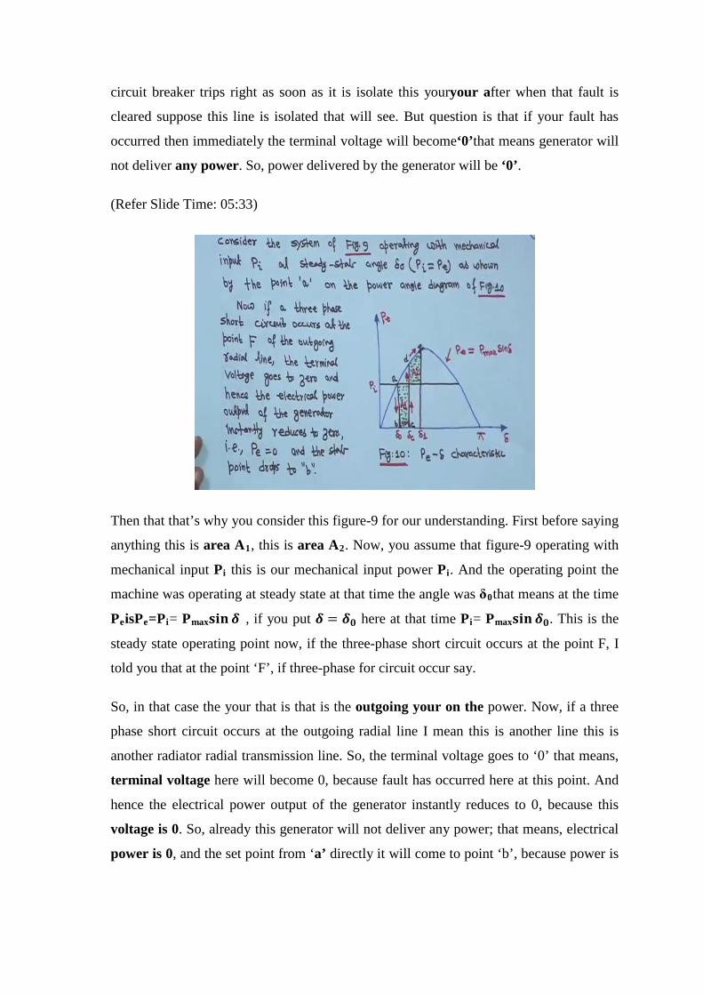
Then that that’s why you consider this figure-9 for our understanding. First before saying
anything this is area A1, this is area A2. Now, you assume that figure-9 operating with
mechanical input Pi this is our mechanical input power Pi. And the operating point the
machine was operating at steady state at that time the angle was δ0that means at the time
PeisPe=Pi= Pmax𝐬𝐬𝐬𝐬𝐬𝐬 𝜹𝜹 , if you put 𝜹𝜹 = 𝜹𝜹𝟎𝟎 here at that time Pi= Pmax𝐬𝐬𝐬𝐬𝐬𝐬 𝜹𝜹𝟎𝟎. This is the
steady state operating point now, if the three-phase short circuit occurs at the point F, I
told you that at the point ‘F’, if three-phase for circuit occur say.
So, in that case the your that is that is the outgoing your on the power. Now, if a three
phase short circuit occurs at the outgoing radial line I mean this is another line this is
another radiator radial transmission line. So, the terminal voltage goes to ‘0’ that means,
terminal voltage here will become 0, because fault has occurred here at this point. And
hence the electrical power output of the generator instantly reduces to 0, because this
voltage is 0. So, already this generator will not deliver any power; that means, electrical
power is 0, and the set point from ‘a’ directly it will come to point ‘b’, because power is
0. So, if it is so; that means, that Piin general greater than youryourPebecause Pe
become 0.
So, in that case what will happen that acceleration area A1, this is the acceleration area
will start to increase. So, we will start to that is acceleration area here, here this one will
start to increase while that is your stat point moves along bc. So, this is b to c, I made
this way arrow, this way arrow and arrow is upward. So, this this will start from point b
to point c. Suppose at time tc, corresponding to that your clearing angle this is 𝜹𝜹𝒄𝒄and at
this time the fault is cleared by the opening of the circuit breaker. So, this fault is cleared,
this circuit breakeropening of that this circuit breaker.
So, as soon as this circuit breaker opens right, so what will happen that immediately this
is the operating point b to c, so that meansthat means the line will become this this line
will transmit power this line will be transmit power, so line will become healthy. So, at
the time that it is your what you call at times tccorresponding clearing time this is
clearing angle 𝜹𝜹𝒄𝒄 the fault is cleared by opening of the line circuit breaker, tcis called the
clearing time and 𝜹𝜹𝒄𝒄 is called clearing angle. So, 𝜹𝜹𝒄𝒄is the clearing angle and the time at
which it is cleared it is called your clearing time.
Now, after the fault is cleared the system again becomes healthy and transmit power
PmaxPe is equal to this is that this is a sine curve that Pe= Pmax𝐬𝐬𝐬𝐬𝐬𝐬 𝜹𝜹 . So, at this point c
the fault is cleared. So, immediately this point will move to‘d’. So, at the timeright at
the time that your and this this point this Paat this point that is Pa value electrical power
value is more than that Pi. So, in that case, now rotor will decelerate, it will decelerate.
So, it will decelerate till the point ‘e’with the same philosophy for equal area criterion
that when area A1, will become area A2, because A2, will begin to increase till the point
‘e’ and when A1 will become A2.

(Refer Slide Time: 09:40)
So, therefore that if area A1becomes in your areaA2 then for stability that clearing angle
𝜹𝜹𝒄𝒄 must be such that this area A1 =areaA2 that means, this area this is actually rectangle
this is actually rectangle. So, it is a height is Piand difference with this 𝜹𝜹𝒄𝒄- 𝜹𝜹𝟎𝟎. So, this
area is Pi* (𝜹𝜹𝒄𝒄- 𝜹𝜹𝟎𝟎)that is area A1that is area A1= your areaA2. So, it will be
𝜹𝜹𝒄𝒄 𝒕𝒕𝟎𝟎𝜹𝜹𝟏𝟏 ∫ 𝒕𝒕𝒕𝒕𝒕𝒕𝒕𝒕 (𝑷𝑷𝒕𝒕 − 𝑷𝑷𝒊𝒊𝜹𝜹𝟏𝟏𝜹𝜹𝒄𝒄
) this is the Pmax this is that peak curve minus this horizontal
line 𝑷𝑷𝒊𝒊. So 𝑷𝑷𝒕𝒕 − 𝑷𝑷𝒊𝒊.
So, if you if youyour what you call that integrate this one, if you integrate this one from
this to this then ultimately, you will get the relationship after this thing
Pmax*( 𝐜𝐜𝐜𝐜𝐬𝐬 𝜹𝜹𝒄𝒄 − 𝐜𝐜𝐜𝐜𝐬𝐬 𝜹𝜹𝟏𝟏)=Pi* (𝜹𝜹𝟏𝟏- 𝜹𝜹𝒄𝒄)
after simplification, this is equations say-47. Now, at 𝜹𝜹 = 𝜹𝜹𝟎𝟎right then Pithat your what
you call Piwill be is equal to Pmax𝐬𝐬𝐬𝐬𝐬𝐬 𝜹𝜹𝟎𝟎 at 𝛿𝛿 = 𝜹𝜹𝟎𝟎 that means that means
Pi=Pmax𝐬𝐬𝐬𝐬𝐬𝐬 𝜹𝜹𝟎𝟎we can write. Therefore, in this equation you put Pi= Pmax𝐬𝐬𝐬𝐬𝐬𝐬 𝜹𝜹𝟎𝟎in this
equation here that means, we are writing that equation yourwhat you call from equation
using question 47 and 48, you put this value here, you put it here.

(Refer Slide Time: 11:29)
Then you will get you willget that
𝐜𝐜𝐜𝐜𝐬𝐬 𝜹𝜹𝒄𝒄 = 𝐜𝐜𝐜𝐜𝐬𝐬 𝜹𝜹𝟏𝟏+(𝜹𝜹𝟏𝟏- 𝜹𝜹𝟎𝟎)*𝐬𝐬𝐬𝐬𝐬𝐬 𝜹𝜹𝟎𝟎
this is equation-49. And 𝜹𝜹𝟏𝟏 is that maximum one it has gone up to this ‘e’ and from this
figure everything is given. So, it is understandable so that means, in order to determine
the critical clearing time we write equation-20 with Pe= 0. So, if you if you see equation-
20, it is
𝒅𝒅𝟐𝟐𝜹𝜹𝒅𝒅𝒕𝒕𝟐𝟐
= 𝝅𝝅𝝅𝝅𝑯𝑯
(𝑷𝑷𝒊𝒊 − 𝑷𝑷𝒕𝒕)
that is equation-20. I am not showing it, it is understandable, but when that your with
your with 𝑷𝑷𝒕𝒕 = 𝟎𝟎, because we have a three phase fault if we have 𝑷𝑷𝒕𝒕 = 𝟎𝟎. Therefore, 𝒅𝒅𝟐𝟐𝜹𝜹𝒅𝒅𝒕𝒕𝟐𝟐
we can write 𝝅𝝅𝝅𝝅𝑯𝑯𝑷𝑷𝒊𝒊 in equation -20. You put 𝑷𝑷𝒕𝒕 = 𝟎𝟎.
Now, if we integrate this equation twice and if you utilize the fact that at t = 0,𝒅𝒅𝜹𝜹𝒅𝒅𝒕𝒕
=0, it
will give you this one I ask you to do this integration right. I am not showing it, but you
just take twice integration put all the initial condition from your intuition and then you
will find this expression. So, you should do this.

(Refer Slide Time: 12:56)
So, I am putting
𝜹𝜹 = 𝝅𝝅𝝅𝝅 ∗ 𝑷𝑷𝒊𝒊𝟐𝟐𝑯𝑯
∗ 𝒕𝒕 + 𝜹𝜹𝟎𝟎
this is equation -51. Now, if t is equal to 𝒕𝒕𝒄𝒄say is a clearing time corresponding to a
clearing angle 𝜹𝜹 = 𝜹𝜹𝒄𝒄then equation-51, you can write. That means, in this equation you
put 𝜹𝜹 = 𝜹𝜹𝒄𝒄 and t =𝒕𝒕𝒄𝒄 then we will get the 𝒕𝒕𝒄𝒄value 𝜹𝜹𝒄𝒄value as well as 𝒕𝒕𝒄𝒄 value.
(Refer Slide Time: 13:38)

That meansthat means if you if you make it then this one the 𝜹𝜹𝒄𝒄 is equal to your then is
equal to 𝝅𝝅𝝅𝝅∗𝑷𝑷𝒊𝒊𝟐𝟐𝑯𝑯
then your𝒕𝒕𝒄𝒄𝟐𝟐 +𝜹𝜹𝟎𝟎. From this equation,
𝒕𝒕𝒄𝒄 = �𝟐𝟐𝑯𝑯(𝜹𝜹𝒄𝒄 − 𝜹𝜹𝟎𝟎)
𝝅𝝅𝝅𝝅𝑷𝑷𝒊𝒊
this is equation 52 right. It is the clearing time. Now, suppose we want to find out what
will be the maximum value of your 𝜹𝜹𝒄𝒄 that is the critical clearing angle, so that is from
the this 𝜹𝜹𝒄𝒄can be obtained from your equation-49. That means just now we have given-
49 from this equation that cosine 𝜹𝜹𝒄𝒄is equal to this sorry 𝐜𝐜𝐜𝐜𝐬𝐬𝜹𝜹𝒄𝒄 is equal to your this one,
this equation. From this equation, 𝜹𝜹𝒄𝒄 can be obtained that is equation-49.
Now, as the clearing of the fault line is delayed faulty line is delayed that means, if we
delay that faulty line that clear your clearing time then A1increases this A1will increase
A1increases and. So, does 𝜹𝜹𝟏𝟏because 𝜹𝜹𝟏𝟏also your will increase to find area A1 =areaA2.
Now, we are I mean if the fault has delayed, but one thing is there will be a limit beyond
that system will become unstable. So, still A1 =A2, if this is the condition.
So, in that case, 𝜹𝜹𝟏𝟏 will become 𝜹𝜹𝒎𝒎that means thisthat meansyour this𝜹𝜹𝟏𝟏 this 𝜹𝜹𝟏𝟏
finally, it will come to a because the 𝜹𝜹𝟏𝟏will come to a value 𝜹𝜹𝒎𝒎 that is the maximum. So,
that is why 𝜹𝜹𝟏𝟏will be this 𝜹𝜹𝒎𝒎 is equal to actually 𝜹𝜹𝒎𝒎𝒎𝒎𝒎𝒎the maximum one that means, if
the if theyour what you call clearing of the faulty line is delayed. So, this is the
maximum that we can get that means my 𝜹𝜹𝒎𝒎this is π this is this is π that means,
𝜹𝜹𝒎𝒎 = 𝝅𝝅 − 𝜹𝜹𝟎𝟎, this is 𝜹𝜹𝒎𝒎. So, for a clearing angle or clearing time larger than this value,
the system will become unstable because you cannot get beyond that. So, system will
become unstable.
(Refer Slide Time: 16:05)
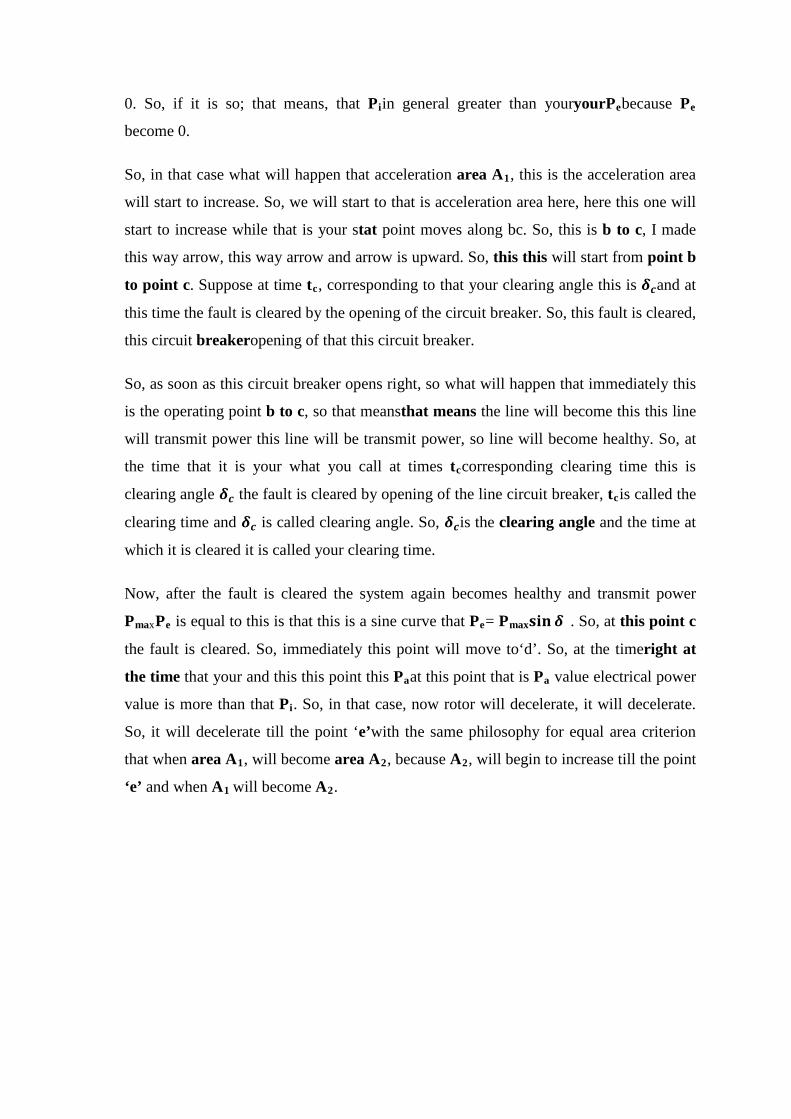
That means the maximum that the that the system would be out the maximum allowable
value of the clearing angle and clearing time for the system to remain stable are known
as critical clearing angle and critical clearing time. That means, this is the your you call
that is that maximum that you can get that is it is called δcriticalor what you call that
critical clearing angle. And corresponding time we give the tcr we call your critical
clearing time, so that is why I am putting it here that the maximum allowable value of
the clearing angle and the clearing time of the system to remain system stable are known
as critical clearing angle or critical clearing time. This is the value beyond that system
will become unstable.
So, from figurefrom this figure only from figure-11, this is figure 11, from figure 11 that
δm = 𝝅𝝅− 𝜹𝜹𝟎𝟎 this is 𝝅𝝅, so 𝝅𝝅− 𝜹𝜹𝟎𝟎. So, if you substitute in to equation-49 this one, just let
me find out that in this equation in this equation if you thisin this equation if you put
like this that your δm = 𝝅𝝅 − 𝜹𝜹𝟎𝟎actually 𝜹𝜹𝟏𝟏 there should not be any confusion. Actually
this is 𝜹𝜹𝟏𝟏= δmand δm = 𝒚𝒚𝒚𝒚𝒚𝒚𝒚𝒚 𝝅𝝅− 𝜹𝜹𝟎𝟎. So, in this equation in this equation you put like
this. Actually 𝜹𝜹𝟏𝟏= δm and δm= because 𝜹𝜹𝟏𝟏maximum it can come up that 𝜹𝜹𝟏𝟏= δmthis is
allowable angle right so that means, here if you have any there should not be any
confusion. So, 𝜹𝜹𝟏𝟏= δm.
And in this equation you put 𝜹𝜹𝟏𝟏= δmand here also and then δm= this one is =𝝅𝝅− 𝜹𝜹𝟎𝟎. So,
if you put here 𝜹𝜹𝟏𝟏= δm= 𝝅𝝅− 𝜹𝜹𝟎𝟎. then you will get 𝐜𝐜𝐜𝐜𝐬𝐬 𝜹𝜹𝒄𝒄𝒚𝒚first that’s why I am first

putting for your understanding putting 𝜹𝜹𝟏𝟏= δm. From this figure this is the maximum
allowable angle for 𝜹𝜹𝟏𝟏𝜹𝜹𝟏𝟏= δmfrom figure-11 here. So that means 𝐜𝐜𝐜𝐜𝐬𝐬 𝜹𝜹𝒄𝒄𝒚𝒚= 𝐜𝐜𝐜𝐜𝐬𝐬 𝜹𝜹𝒎𝒎 +
(δm–𝜹𝜹𝟎𝟎) ∗ 𝐬𝐬𝐬𝐬𝐬𝐬𝜹𝜹𝟎𝟎 that equation your-49, we are putting 𝜹𝜹𝟏𝟏= δm and then δm= 𝝅𝝅 − 𝜹𝜹𝟎𝟎.
Now, you put 𝝅𝝅 − 𝜹𝜹𝟎𝟎, you will get 𝐜𝐜𝐜𝐜𝐬𝐬 𝜹𝜹𝒄𝒄𝒚𝒚 = (𝝅𝝅− 𝟐𝟐𝜹𝜹𝟎𝟎) ∗ 𝐬𝐬𝐬𝐬𝐬𝐬 𝜹𝜹𝟎𝟎 − 𝐜𝐜𝐜𝐜𝐬𝐬 𝜹𝜹𝟎𝟎 this is
equation-53. So, that is that is how one will get that your one can find out if we if 𝜹𝜹𝟎𝟎is
known to you can compute 𝜹𝜹𝒄𝒄𝒚𝒚 right critical clearing angle. So, using equation-52using
equation-52 that means, this equation, this equation, this equation that
𝒕𝒕𝒄𝒄 = �𝟐𝟐𝑯𝑯(𝜹𝜹𝒄𝒄 − 𝜹𝜹𝟎𝟎)
𝝅𝝅𝝅𝝅𝑷𝑷𝒊𝒊
here you put that instead of 𝒕𝒕𝒄𝒄, 𝒕𝒕𝒄𝒄𝒚𝒚 and instead of 𝜹𝜹𝒄𝒄 ,𝜹𝜹𝒄𝒄𝒚𝒚then you will get critical
clearing time.
(Refer Slide Time: 19:48)
So, in this equation just in place of 𝒕𝒕𝒄𝒄you put 𝒕𝒕𝒄𝒄𝒚𝒚, and in place of 𝜹𝜹𝒄𝒄you put 𝜹𝜹𝒄𝒄𝒚𝒚. So, if
you do so then you will get𝒕𝒕𝒄𝒄𝒚𝒚 = �𝟐𝟐𝑯𝑯(𝜹𝜹𝒄𝒄𝒚𝒚−𝜹𝜹𝟎𝟎)𝝅𝝅𝝅𝝅∗𝑷𝑷𝒊𝒊
this is equation -54. And 𝜹𝜹𝒄𝒄𝒚𝒚 can be
computed that as equation given in equation-53 this you know. So, this is how one can
compute that critical clearing time. This is of course, your approximate thing, but this is
a good exercise using equal area criterion.
Now, next one is little bit we have to understand. So, for suppose next one is we have a
double circuit line before saying this time just see we have a double circuit line. So, this
is double circuit line. It is single machine infinite bus of course, this is generator multi
machine system here we cannot study, it is a very lengthy procedure, and for multi
machine system one has to go for iterative technique. So, we will not do that. Only for
undergraduate and for general idea for undergraduate student as well as those were you
know I mean have passed out passed out engineering for them, it will be helpful thisthis
this your this single machine infinite bus system. So, there is a transformer in anyway.
So, this is bus-1, bus-2 this is a double circuit line and suppose they fault has occurred
for bus some mark I have made 1, 2, another bus some I have marked 3, but not
necessary for this analysis. Suppose, a fault has occurred which is little bit away from the
substation sorry from this bus-1, this fault is little bit away that means, as soon as fault
has occurred that it will occur some that although your equivalent this thing what you
call the reactive impedance or if resistance is neglected. So, it is a reactance it will
increase, but anyway a fault has occurred three phase fault at a distance your of this thing
at some distance from the bus-1. So, this is this isyour this is figure-12 the double circuit
transmission line a fault has occurred. Now,now this one this one now consider the fault
location at ‘F’. I told you this is the third location at ‘F’, it is at some distance from bus-
1.
(Refer Slide Time: 22:02)

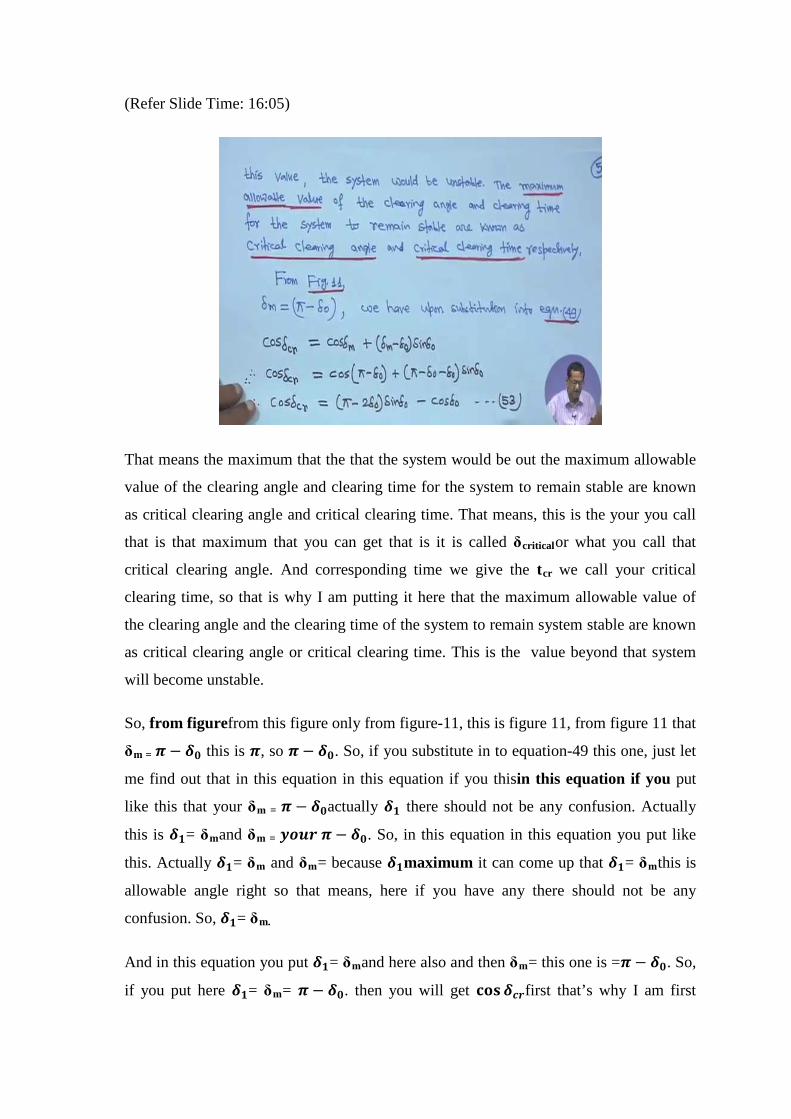
So, this is and this side is the sending end, this is sending end, of course, you know this
and this is receiving end. So, assume that the input power Pithen look at this graph input
power Pithis horizontal line is constant and the machine was operating steadily and
delivering power to the system with an power angle δ0, this is δ0. And it was your what
you call delivering power and it is shown in figure that means shown in figure-13. That
means, this green curve this green curve actually this is this is called curve ‘A’ right this
is before fault that means, pre fault this is before fault. So, this is your graph ‘A’, this is I
have marked as ‘A’.
Now,nowpower angle curve corresponding the pre fault condition is given curve A. So,
this is your curve ‘A’ the green one. Now, as the fault location with fault location ‘F’ at
your from the sending end, little bit away from the sending end this is little not at the
sending end it is away from the sending end this fault location, the equivalent transfer
reactance between bus bar is increased. That means, this we will see through an example
later on that equivalent transfer in the your reactance will increase because it away from
the this bus right.
(Refer Slide Time: 23:47)
So, power so in that case what will happen reactance as increase and you know power
transfer is equal to in general𝑽𝑽𝟏𝟏𝑽𝑽𝟐𝟐𝒎𝒎𝐬𝐬𝐬𝐬𝐬𝐬𝜹𝜹, if x increases then naturally power transfer will
decrease. So, that means, the power transfer capability and the power angle curve is
represented by curve ‘B’. So, as soon asas soon as there is a fault, so during fault this

graphB’ this is actually during fault right and suddenly the power transfer capability has
decreased. So, that is why this that means, initially it was operating at point ‘a’, but now
suddenly this has your what you call has come to graphB’ this is actually during fault.
So, during pre-fault, during fault and post fault later we will see the three condition.
So, in that case what will happen that as soon as it is falling here as soon as it is falling to
this that means, this point will be shifting to ‘b’, but it will never be 0, because it is
double circuit line and fault has occurred away from the substation. Its transfer reactance
will increase to some extent and naturally that this curve will be the black one this black
one and this will be your curve B’, this is during fault I have written here. This curve is
during fault. So, from ‘a’ the point will be shifting to ‘b’.
So, as soon as it is coming from here, so that meanmechanical input power will be
greater than during fault greater than this electrical power because this point ‘b’ is below
point ‘a’. So, at that time, what will happen mess this δ1this is the initial operating angle.
So, δ this this angle δ1will count will be your continuously increasing. So, at the so in
that case what will happen, this is your machine will Pi> Pe because this is during fault,
so machine will accelerate. So, it will it will store kinetic energy during acceleration
and after some time say at δ =δ1, the fault is clear and line is isolated; that means, this
fault is clear and this line is isolated. So, as soon as it will be single line it is isolated this
power transfer capability will increase.
So, in that case this is that this is the your grapgh-‘c’ the blue one this is your after fault
or post fault right this is, that means, that your the initially it was at ‘a’, now a fault has
occurred during fault that power transfer capability had decreased. So, this graph is the
black one it has come to this point that means ‘a’ has come to ‘b’. Now, Piis greater
than your this mechanical power this Pithis is greater than your input power is greater
than this electrical power. So, rotor will be your accelerating. So, it will store kinetic
energy and δ also, this is angle δ this is δ1it continuously increase. So, at some point that
fault is cleared that means, this fault is cleared and line is isolated, this line is isolated. It
is not there it is not there the post fault condition or after fault condition only 1 to 2 this
line is there, this is not there
So, in that case that graph this figure this this single line now. So, your this power graph
will be that graph ‘c’ that is after fault and thisδ this point that your from your as it is

moving from ‘b’ to ‘c’δ1is increasing on this graph, it is moving b’ to ‘c’, but at δ1the
fault is cleared. So, it will immediately it will jump to that point that after fault and this
curve this sine curve will come. And and this is rotor has your your stored kinetic
energy due to acceleration. So, after that what will happen this it will be it will be
decelerating same philosophy as equal area criterion. So, finally, it will it will reach to
this point ‘F’, where your accelerating energy A1 is equal to decelerating energy A2.
And after that as your this one this electrical power here on the blue graph at point ‘a’if it
is greater than Pi. So, basic basically rotor will oscillateoscillate back and forth that is
your this point at this point right. If these ‘e’ point is there around this here, so it will not
oscillate and you are in back and back and forth. And finally, that intersection of these
look at this blue line, I have made it Piand this is also blue line wherever wherever it will
come this will be your this steady state I have not marked here by dot or anything, but
this will be final steady state your operating point.
Here if you want here something I mean this point, this point, this point it will because
rotor will oscillate back and forth and finally, it will be settled at this point because
power wasPiinput power wasPi. So, somewhere on the blue graph not thegreen one
green one blue one it will be settled after oscillating. And rotor will oscillate actually at
its natural frequency and then the machine has the damping, so because of his own
ownthis is this damping effect it willsubsides subsides the your that rotor oscillation. So,
finally, it will settle on this here later will take an example at the time I have marked this
angle by 𝜹𝜹𝒎𝒎𝟏𝟏 . So, this is the philosophy for your do your yourfordouble circuit your
transmission line single machine infinite bus case that area 1must be equal to area 2 and
this philosophy same as equal area criterion here also equal area criterion.
So, all these things your all these all these things I have shown in this black your green
one - before fault, black one - during fault, and this one after fault. So, hope this will be
no there will be no difficulty at all philosophy will remain same as equal area criterion.
So, so rest whatever I said that everythingeverything is written here right. So, power
angle curve corresponding to the pre fault condition is given by A, this this one. Then
when fault look fault location and ‘F’ away from the sending end I told you that transfer
reactance will increase, so that is represented by curve B, this is curve B. This is during
fault and when fault is cleared; that means, when single line is operating this is there

your this is this is isolated only this line is there. So, in that case your this blue curve is
the your power power angle curve. So, all these things written here whatever I said.
So, I hope when you will read it, so you pause it and read it whatever I said everything is
mention here. So, that means, if these two area I mean if A1= A2if these two area equal
then we will find out all theyour your this thing and your clearing angle and everything.
So, everything is written here whatever I have told. Look at all this paragraph since Pe is
still greater than Pi, the rotor continues to decelerate and the path is retraced along the
power angle curve passing through ‘e’, I told you that this is along the retraced along the
path passing through ‘e’ right through this point ‘e’here, here, here right.
So, rotor angle will then oscillate back and forth around e at its natural frequency. So, it
will oscillate around ‘e’ at its natural frequency. And finally, the damping presented in
the machine will cause this oscillation to subside and a new steady state operation will be
established at the intersection of Piand curve ‘C’. I told you and the intersection of this
Pithe blue one and this blue curve this will be your what you call the steady state
operating point here here right.
So, next is now what will be the maximum criticalyour clearing in this case for this kind
of problem what is the maximum your critical clearing angleδcr. The critical clearing
angle is reached when any further increases δ1that means, this δ1this is δ1 it is increasing
right. What will be maximum one increasing δ1causes the area A2 that means, this area
A2representing decelerating energy to become less than the area representing the
acceleration energy.
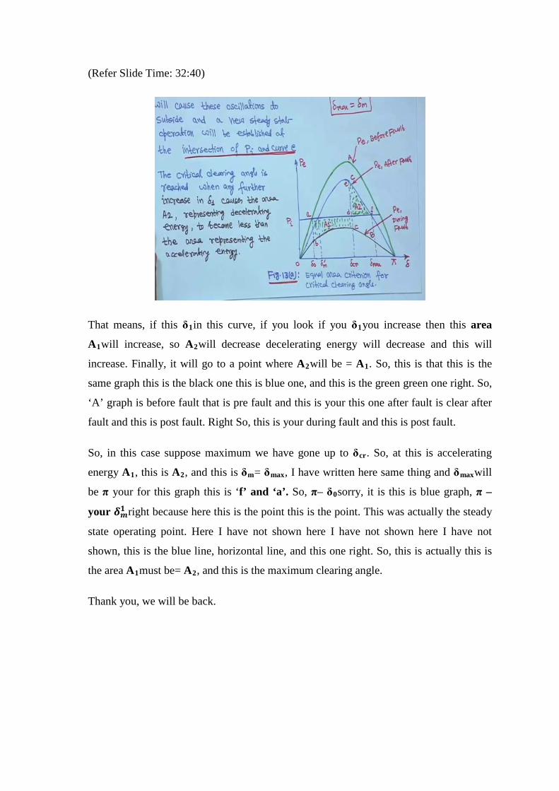
(Refer Slide Time: 32:40)
That means, if this δ1in this curve, if you look if you δ1you increase then this area
A1will increase, so A2will decrease decelerating energy will decrease and this will
increase. Finally, it will go to a point where A2will be = A1. So, this is that this is the
same graph this is the black one this is blue one, and this is the green green one right. So,
‘A’ graph is before fault that is pre fault and this is your this one after fault is clear after
fault and this is post fault. Right So, this is your during fault and this is post fault.
So, in this case suppose maximum we have gone up to δcr. So, at this is accelerating
energy A1, this is A2, and this is δm= δmax, I have written here same thing and δmaxwill
be π your for this graph this is ‘f’ and ‘a’. So, π– δ0sorry, it is this is blue graph, π –
your 𝜹𝜹𝒎𝒎𝟏𝟏 right because here this is the point this is the point. This was actually the steady
state operating point. Here I have not shown here I have not shown here I have not
shown, this is the blue line, horizontal line, and this one right. So, this is actually this is
the area A1must be= A2, and this is the maximum clearing angle.
Thank you, we will be back.