power systems 0595, 5095, and 7311 model d20 removal … · power systems 0595, 5095, and 7311...
TRANSCRIPT
Power Systems
0595, 5095, and 7311 model D20removal and replacement procedures
���


Power Systems
0595, 5095, and 7311 model D20removal and replacement procedures
���
NoteBefore using this information and the product it supports, read the information in “Notices,” onpage 53, “Safety notices” on page v, the IBM Systems Safety Notices manual, G229-9054, and theIBM Environmental Notices and User Guide, Z125–5823.
This edition applies to IBM® Power Systems® servers that contain the POWER6™ processor and to all associatedmodels.
© Copyright International Business Machines Corporation 2008, 2009.US Government Users Restricted Rights – Use, duplication or disclosure restricted by GSA ADP Schedule Contractwith IBM Corp.
Contents
Safety notices . . . . . . . . . . . . . . . . . . . . . . . . . . . . . . . . . v
0595, 5095, and 7311-D20 removal and replacement procedures . . . . . . . . . . . 1External cables. . . . . . . . . . . . . . . . . . . . . . . . . . . . . . . . . . . 2Internal cables . . . . . . . . . . . . . . . . . . . . . . . . . . . . . . . . . . . 3Air moving device (fan) . . . . . . . . . . . . . . . . . . . . . . . . . . . . . . . 4Device board . . . . . . . . . . . . . . . . . . . . . . . . . . . . . . . . . . . 9Disk drive . . . . . . . . . . . . . . . . . . . . . . . . . . . . . . . . . . . . 15
Replacing the disk drive using AIX . . . . . . . . . . . . . . . . . . . . . . . . . . 16Replacing the disk drive using Linux . . . . . . . . . . . . . . . . . . . . . . . . . . 19
Preparing to remove the disk drive . . . . . . . . . . . . . . . . . . . . . . . . . 19Removing the disk drive . . . . . . . . . . . . . . . . . . . . . . . . . . . . . 22Replacing the disk drive . . . . . . . . . . . . . . . . . . . . . . . . . . . . . 24
Replacing the disk drive nonconcurrently . . . . . . . . . . . . . . . . . . . . . . . . 26Replacing the disk drive using IBM i . . . . . . . . . . . . . . . . . . . . . . . . . . 29Rebuilding data on a replacement disk drive using Linux . . . . . . . . . . . . . . . . . . . 36
Display panel. . . . . . . . . . . . . . . . . . . . . . . . . . . . . . . . . . . 36Network interface card . . . . . . . . . . . . . . . . . . . . . . . . . . . . . . . 38Peripheral component interconnect card . . . . . . . . . . . . . . . . . . . . . . . . . . 41Power supply . . . . . . . . . . . . . . . . . . . . . . . . . . . . . . . . . . 45Selectable PCI card . . . . . . . . . . . . . . . . . . . . . . . . . . . . . . . . . 49I/O backplane . . . . . . . . . . . . . . . . . . . . . . . . . . . . . . . . . . 50
Appendix. Notices . . . . . . . . . . . . . . . . . . . . . . . . . . . . . . . 53Trademarks . . . . . . . . . . . . . . . . . . . . . . . . . . . . . . . . . . . 54Electronic emission notices . . . . . . . . . . . . . . . . . . . . . . . . . . . . . . 54
Class A Notices . . . . . . . . . . . . . . . . . . . . . . . . . . . . . . . . . 54Terms and conditions . . . . . . . . . . . . . . . . . . . . . . . . . . . . . . . . 58
© Copyright IBM Corp. 2008, 2009 iii

iv
Safety notices
Safety notices may be printed throughout this guide:v DANGER notices call attention to a situation that is potentially lethal or extremely hazardous to
people.v CAUTION notices call attention to a situation that is potentially hazardous to people because of some
existing condition.v Attention notices call attention to the possibility of damage to a program, device, system, or data.
World Trade safety information
Several countries require the safety information contained in product publications to be presented in theirnational languages. If this requirement applies to your country, a safety information booklet is includedin the publications package shipped with the product. The booklet contains the safety information inyour national language with references to the U.S. English source. Before using a U.S. English publicationto install, operate, or service this product, you must first become familiar with the related safetyinformation in the booklet. You should also refer to the booklet any time you do not clearly understandany safety information in the U.S. English publications.
German safety information
Das Produkt ist nicht für den Einsatz an Bildschirmarbeitsplätzen im Sinne § 2 derBildschirmarbeitsverordnung geeignet.
Laser safety information
IBM® servers can use I/O cards or features that are fiber-optic based and that utilize lasers or LEDs.
Laser compliance
All lasers are certified in the U.S. to conform to the requirements of DHHS 21 CFR Subchapter J for class1 laser products. Outside the U.S., they are certified to be in compliance with IEC 60825 as a class 1 laserproduct. Consult the label on each part for laser certification numbers and approval information.
CAUTION:This product might contain one or more of the following devices: CD-ROM drive, DVD-ROM drive,DVD-RAM drive, or laser module, which are Class 1 laser products. Note the following information:
v Do not remove the covers. Removing the covers of the laser product could result in exposure tohazardous laser radiation. There are no serviceable parts inside the device.
v Use of the controls or adjustments or performance of procedures other than those specified hereinmight result in hazardous radiation exposure.
(C026)
CAUTION:Data processing environments can contain equipment transmitting on system links with laser modulesthat operate at greater than Class 1 power levels. For this reason, never look into the end of an opticalfiber cable or open receptacle. (C027)
CAUTION:This product contains a Class 1M laser. Do not view directly with optical instruments. (C028)
© Copyright IBM Corp. 2008, 2009 v
CAUTION:Some laser products contain an embedded Class 3A or Class 3B laser diode. Note the followinginformation: laser radiation when open. Do not stare into the beam, do not view directly with opticalinstruments, and avoid direct exposure to the beam. (C030)
Power and cabling information for NEBS (Network Equipment-Building System)GR-1089-CORE
The following comments apply to the IBM servers that have been designated as conforming to NEBS(Network Equipment-Building System) GR-1089-CORE:
The equipment is suitable for installation in the following:v Network telecommunications facilitiesv Locations where the NEC (National Electrical Code) applies
The intrabuilding ports of this equipment are suitable for connection to intrabuilding or unexposedwiring or cabling only. The intrabuilding ports of this equipment must not be metallically connected to theinterfaces that connect to the OSP (outside plant) or its wiring. These interfaces are designed for use asintrabuilding interfaces only (Type 2 or Type 4 ports as described in GR-1089-CORE) and require isolationfrom the exposed OSP cabling. The addition of primary protectors is not sufficient protection to connectthese interfaces metallically to OSP wiring.
Note: All Ethernet cables must be shielded and grounded at both ends.
The ac-powered system does not require the use of an external surge protection device (SPD).
The dc-powered system employs an isolated DC return (DC-I) design. The DC battery return terminalshall not be connected to the chassis or frame ground.
vi

0595, 5095, and 7311-D20 removal and replacementprocedures
Use the removal and replacement procedures when you repair, maintain, or exchange system parts foryour 0595, 5095, or 7311-D20 expansion unit.
Before you begin a replacement, perform these tasks:1. If you are performing a replacement procedure that might put your data at risk, ensure, if possible,
that you have a current backup of your system or logical partition (including operating systems,licensed programs, and data).
2. Review the installation or replacement procedure for the feature or part.3. Note the significance of color on your system. Blue or terra-cotta on a part of the hardware indicates
a touch point where you can grip the hardware to remove it from or install it in the system, open orclose a latch, and so on. Terra-cotta might also indicate that the part can be removed and replacedwith the system or logical partition power on.
4. Ensure that you have access to a medium, flat-blade screwdriver.5. If parts are incorrect, missing, or visibly damaged, contact your service provider or next level of
support.
© Copyright IBM Corp. 2008, 2009 1
DANGER
When working on or around the system, observe the following precautions:
Electrical voltage and current from power, telephone, and communication cables are hazardous. Toavoid a shock hazard:v Connect power to this unit only with the IBM provided power cord. Do not use the IBM
provided power cord for any other product.v Do not open or service any power supply assembly.v Do not connect or disconnect any cables or perform installation, maintenance, or reconfiguration
of this product during an electrical storm.v The product might be equipped with multiple power cords. To remove all hazardous voltages,
disconnect all power cords.v Connect all power cords to a properly wired and grounded electrical outlet. Ensure that the outlet
supplies proper voltage and phase rotation according to the system rating plate.v Connect any equipment that will be attached to this product to properly wired outlets.v When possible, use one hand only to connect or disconnect signal cables.v Never turn on any equipment when there is evidence of fire, water, or structural damage.v Disconnect the attached power cords, telecommunications systems, networks, and modems before
you open the device covers, unless instructed otherwise in the installation and configurationprocedures.
v Connect and disconnect cables as described in the following procedures when installing, moving,or opening covers on this product or attached devices.
To Disconnect:1. Turn off everything (unless instructed otherwise).2. Remove the power cords from the outlets.3. Remove the signal cables from the connectors.4. Remove all cables from the devices
To Connect:1. Turn off everything (unless instructed otherwise).2. Attach all cables to the devices.3. Attach the signal cables to the connectors.4. Attach the power cords to the outlets.5. Turn on the devices.
(D005)
Attention: Failure to follow the step-by-step sequence for FRU removal or installation may result inFRU or system damage.
Use the following precautions whenever you handle electronic components or cables.v The electrostatic discharge (ESD) kit and the ESD wrist strap must be used when handling logic cards,
SCMs, MCMs, electronic boards, and disk drives.v Keep all electronic components in the shipping container or envelope until you are ready to install
them.v If you remove, then reinstall an electronic component, temporarily place the component on an ESD pad
or blanket.
External cablesUse this procedure to service the external cables.
2
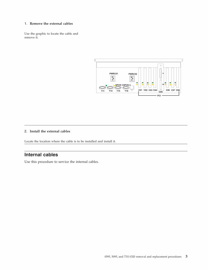
1. Remove the external cables
Use the graphic to locate the cable andremove it.
2. Install the external cables
Locate the location where the cable is to be installed and install it.
Internal cablesUse this procedure to service the internal cables.
0595, 5095, and 7311-D20 removal and replacement procedures 3

1. Remove the internal cables
1. Remove the power cord.
2. Use the graphic to locate the cable andremove it.
2. Install the internal cables
1. Locate the location where the cable is to be installed and install it.
2. Install the power cord.
Air moving device (fan)Use this procedure to service the air moving device (fan).
4

1. Place unit into service position
Attention: When placing yoursystem into the service position,all stability plates must be firmlyin position to prevent the rackfrom tipping over. Ensure thatonly one system unit is in theservice position at a time.
1. Open the front rack door.
2. If your system is equippedwith two blue thumbscrewssecuring it to the rack, removethe thumbscrews (A) at thistime. The screws are located onthe right and left side of thebezel, just above eachsubsystem release latch.
3. Release the subsystem releaselatches (B).
4. Pull the system unit out fromthe rack until the rails are fullyextended.
5. Note: When the system railsare fully extended, safetylatches on the slide rails lockinto place. This action preventsthe system from beingaccidentally pulled out too farand dropped.
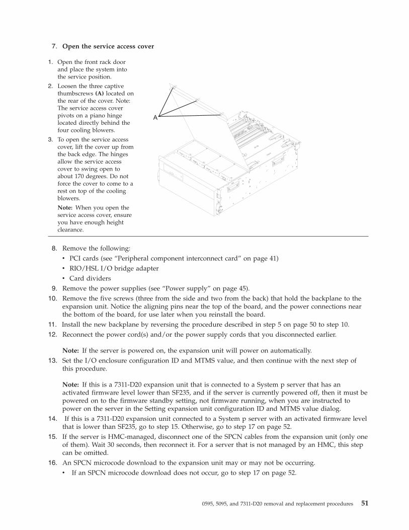
2. Open the service access cover
1. Open the front rack doorand place the system intothe service position.
2. Loosen the three captivethumbscrews (A) located onthe rear of the cover. Note:The service access coverpivots on a piano hingelocated directly behind thefour cooling blowers.
3. To open the service accesscover, lift the cover up fromthe back edge. The hingesallow the service accesscover to swing open toabout 170 degrees. Do notforce the cover to come to arest on top of the coolingblowers.
Note: When you open theservice access cover, ensureyou have enough heightclearance.
0595, 5095, and 7311-D20 removal and replacement procedures 5
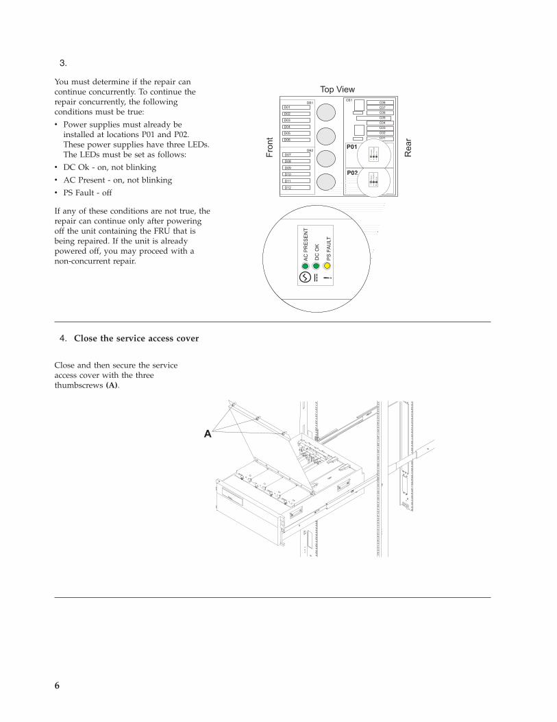
3.
You must determine if the repair cancontinue concurrently. To continue therepair concurrently, the followingconditions must be true:
v Power supplies must already beinstalled at locations P01 and P02.These power supplies have three LEDs.The LEDs must be set as follows:
v DC Ok - on, not blinking
v AC Present - on, not blinking
v PS Fault - off
If any of these conditions are not true, therepair can continue only after poweringoff the unit containing the FRU that isbeing repaired. If the unit is alreadypowered off, you may proceed with anon-concurrent repair.
4. Close the service access cover
Close and then secure the serviceaccess cover with the threethumbscrews (A).
6
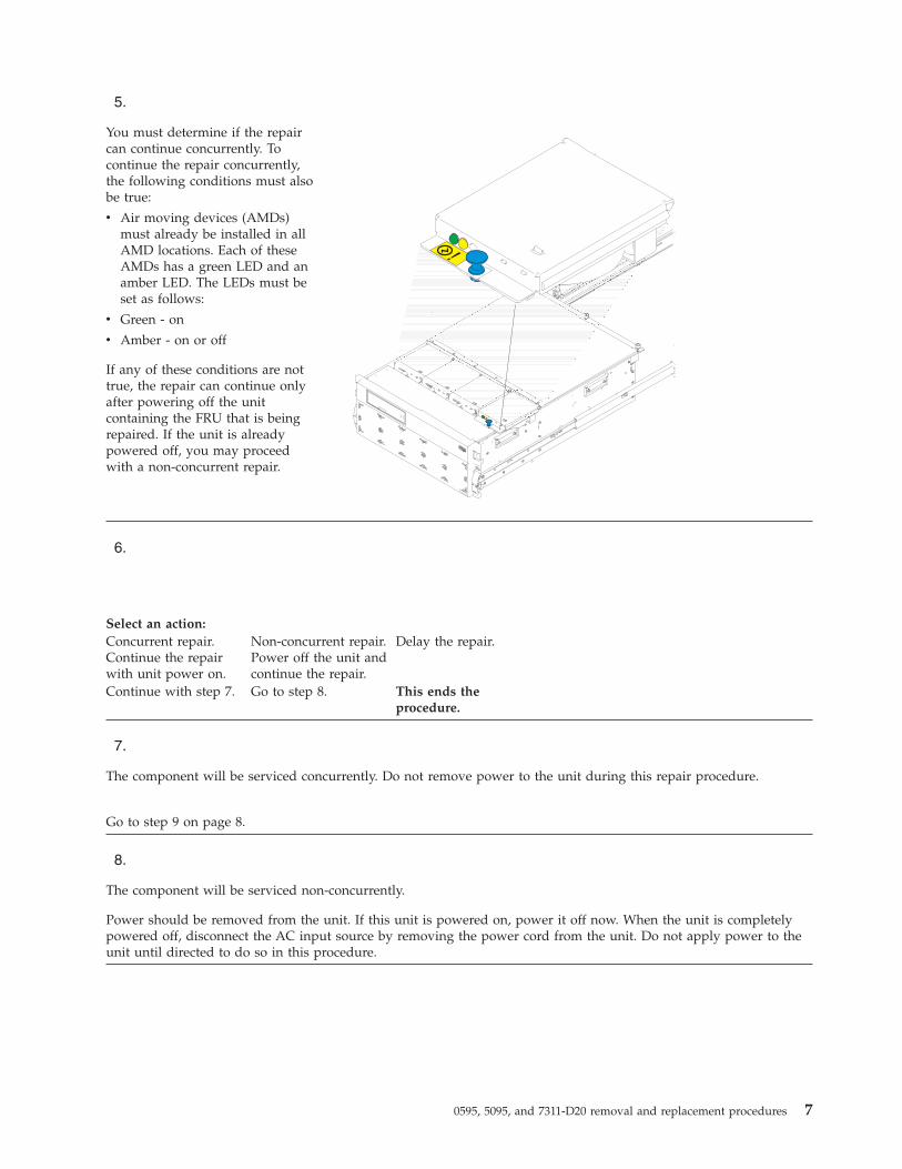
5.
You must determine if the repaircan continue concurrently. Tocontinue the repair concurrently,the following conditions must alsobe true:
v Air moving devices (AMDs)must already be installed in allAMD locations. Each of theseAMDs has a green LED and anamber LED. The LEDs must beset as follows:
v Green - on
v Amber - on or off
If any of these conditions are nottrue, the repair can continue onlyafter powering off the unitcontaining the FRU that is beingrepaired. If the unit is alreadypowered off, you may proceedwith a non-concurrent repair.
6.
Select an action:Concurrent repair.Continue the repairwith unit power on.
Non-concurrent repair.Power off the unit andcontinue the repair.
Delay the repair.
Continue with step 7. Go to step 8. This ends theprocedure.
7.
The component will be serviced concurrently. Do not remove power to the unit during this repair procedure.
Go to step 9 on page 8.
8.
The component will be serviced non-concurrently.
Power should be removed from the unit. If this unit is powered on, power it off now. When the unit is completelypowered off, disconnect the AC input source by removing the power cord from the unit. Do not apply power to theunit until directed to do so in this procedure.
0595, 5095, and 7311-D20 removal and replacement procedures 7
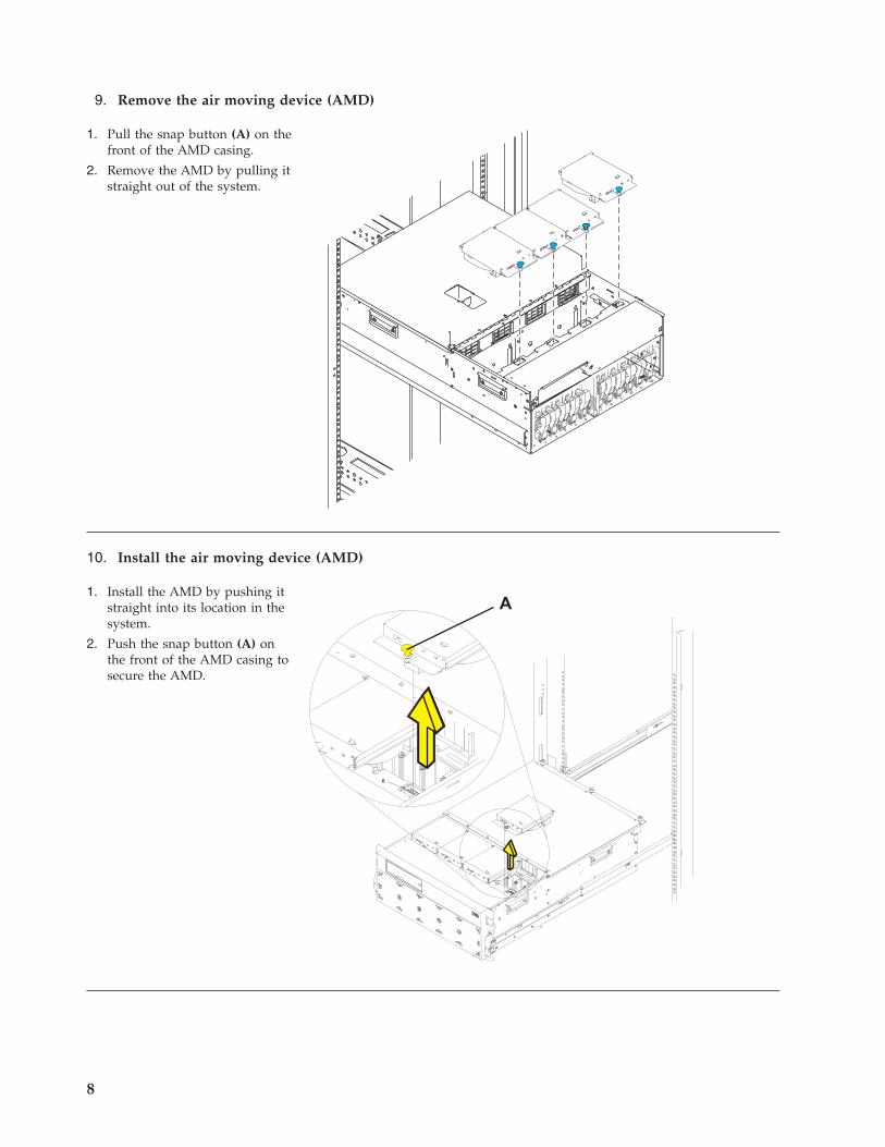
9. Remove the air moving device (AMD)
1. Pull the snap button (A) on thefront of the AMD casing.
2. Remove the AMD by pulling itstraight out of the system.
10. Install the air moving device (AMD)
1. Install the AMD by pushing itstraight into its location in thesystem.
2. Push the snap button (A) onthe front of the AMD casing tosecure the AMD.
8
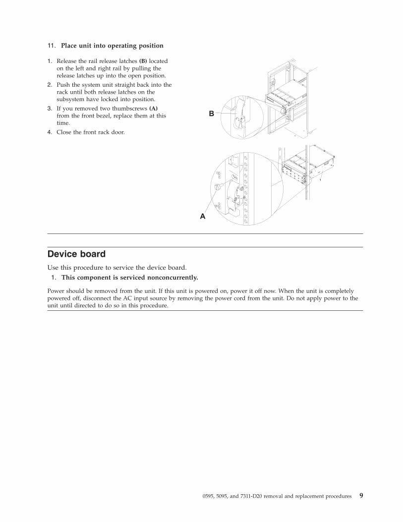
11. Place unit into operating position
1. Release the rail release latches (B) locatedon the left and right rail by pulling therelease latches up into the open position.
2. Push the system unit straight back into therack until both release latches on thesubsystem have locked into position.
3. If you removed two thumbscrews (A)from the front bezel, replace them at thistime.
4. Close the front rack door.
Device boardUse this procedure to service the device board.1. This component is serviced nonconcurrently.
Power should be removed from the unit. If this unit is powered on, power it off now. When the unit is completelypowered off, disconnect the AC input source by removing the power cord from the unit. Do not apply power to theunit until directed to do so in this procedure.
0595, 5095, and 7311-D20 removal and replacement procedures 9
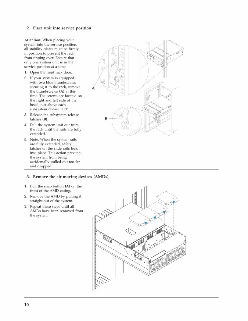
2. Place unit into service position
Attention: When placing yoursystem into the service position,all stability plates must be firmlyin position to prevent the rackfrom tipping over. Ensure thatonly one system unit is in theservice position at a time.
1. Open the front rack door.
2. If your system is equippedwith two blue thumbscrewssecuring it to the rack, removethe thumbscrews (A) at thistime. The screws are located onthe right and left side of thebezel, just above eachsubsystem release latch.
3. Release the subsystem releaselatches (B).
4. Pull the system unit out fromthe rack until the rails are fullyextended.
5. Note: When the system railsare fully extended, safetylatches on the slide rails lockinto place. This action preventsthe system from beingaccidentally pulled out too farand dropped.
3. Remove the air moving devices (AMDs)
1. Pull the snap button (A) on thefront of the AMD casing.
2. Remove the AMD by pulling itstraight out of the system.
3. Repeat these steps until allAMDs have been removed fromthe system.
10
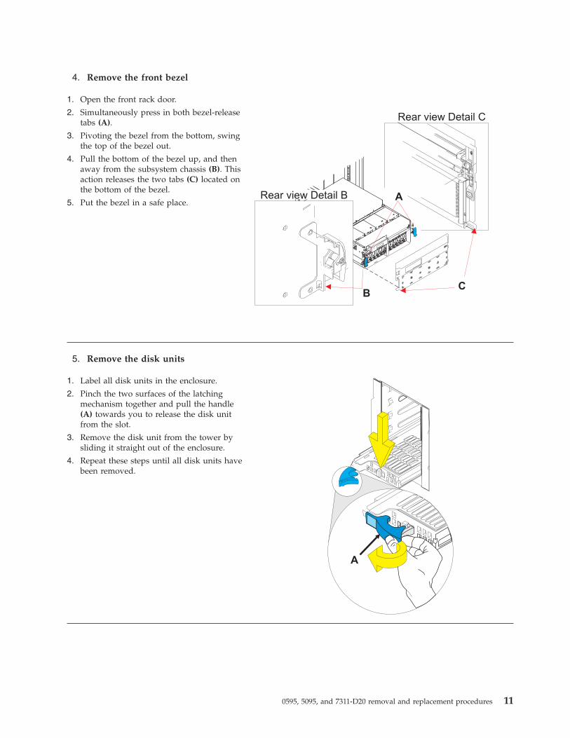
4. Remove the front bezel
1. Open the front rack door.
2. Simultaneously press in both bezel-releasetabs (A).
3. Pivoting the bezel from the bottom, swingthe top of the bezel out.
4. Pull the bottom of the bezel up, and thenaway from the subsystem chassis (B). Thisaction releases the two tabs (C) located onthe bottom of the bezel.
5. Put the bezel in a safe place.
5. Remove the disk units
1. Label all disk units in the enclosure.
2. Pinch the two surfaces of the latchingmechanism together and pull the handle(A) towards you to release the disk unitfrom the slot.
3. Remove the disk unit from the tower bysliding it straight out of the enclosure.
4. Repeat these steps until all disk units havebeen removed.
0595, 5095, and 7311-D20 removal and replacement procedures 11
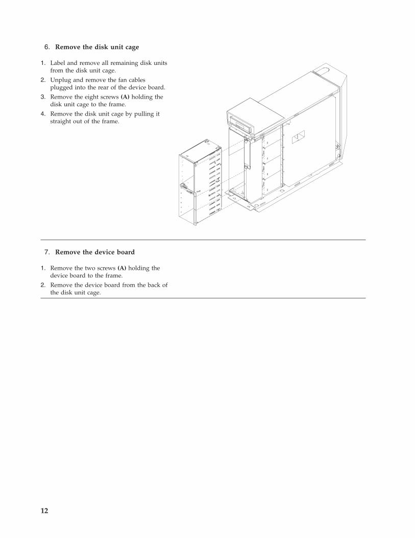
6. Remove the disk unit cage
1. Label and remove all remaining disk unitsfrom the disk unit cage.
2. Unplug and remove the fan cablesplugged into the rear of the device board.
3. Remove the eight screws (A) holding thedisk unit cage to the frame.
4. Remove the disk unit cage by pulling itstraight out of the frame.
7. Remove the device board
1. Remove the two screws (A) holding thedevice board to the frame.
2. Remove the device board from the back ofthe disk unit cage.
12
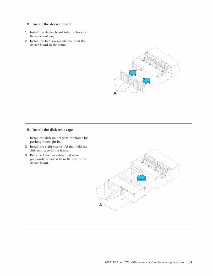
8. Install the device board
1. Install the device board into the back ofthe disk unit cage.
2. Install the two screws (A) that hold thedevice board to the frame.
9. Install the disk unit cage
1. Install the disk unit cage to the frame bypushing it straight in.
2. Install the eight screws (A) that hold thedisk unit cage to the frame.
3. Reconnect the fan cables that werepreviously removed from the rear of thedevice board.
0595, 5095, and 7311-D20 removal and replacement procedures 13
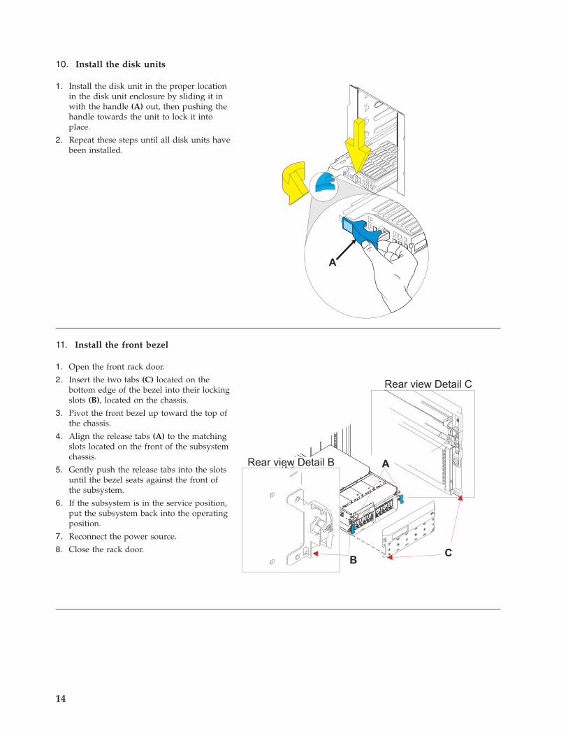
10. Install the disk units
1. Install the disk unit in the proper locationin the disk unit enclosure by sliding it inwith the handle (A) out, then pushing thehandle towards the unit to lock it intoplace.
2. Repeat these steps until all disk units havebeen installed.
11. Install the front bezel
1. Open the front rack door.
2. Insert the two tabs (C) located on thebottom edge of the bezel into their lockingslots (B), located on the chassis.
3. Pivot the front bezel up toward the top ofthe chassis.
4. Align the release tabs (A) to the matchingslots located on the front of the subsystemchassis.
5. Gently push the release tabs into the slotsuntil the bezel seats against the front ofthe subsystem.
6. If the subsystem is in the service position,put the subsystem back into the operatingposition.
7. Reconnect the power source.
8. Close the rack door.
14
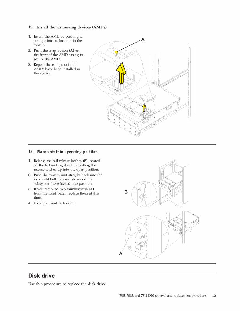
12. Install the air moving devices (AMDs)
1. Install the AMD by pushing itstraight into its location in thesystem.
2. Push the snap button (A) onthe front of the AMD casing tosecure the AMD.
3. Repeat these steps until allAMDs have been installed inthe system.
13. Place unit into operating position
1. Release the rail release latches (B) locatedon the left and right rail by pulling therelease latches up into the open position.
2. Push the system unit straight back into therack until both release latches on thesubsystem have locked into position.
3. If you removed two thumbscrews (A)from the front bezel, replace them at thistime.
4. Close the front rack door.
Disk driveUse this procedure to replace the disk drive.
0595, 5095, and 7311-D20 removal and replacement procedures 15
Your system can be powered off or powered on when you replace the disk drive. If the system is running, you canreplace a disk drive with the power on. If it is not, or if the disk drive to be replaced is in the AIX® or Linux® rootvolume group (rootvg) and it is not protected with either a redundant array of independent disks (RAID) ormirroring, use the procedure for replacing the disk drive with the power off.
1.
Do you want to replace the disk drive concurrently with system operations and the unit powered on?
Yes No↓ Go to Replace the disk drive nonconcurrently.
2.
Choose the procedure for the operating system running in the partition that the disk drive resource is assigned to.
For AIX, go to Replace the disk drive using AIX .
For Linux, go to Replace the disk drive using Linux .
For IBM i, go to Replace the disk drive using IBM i.
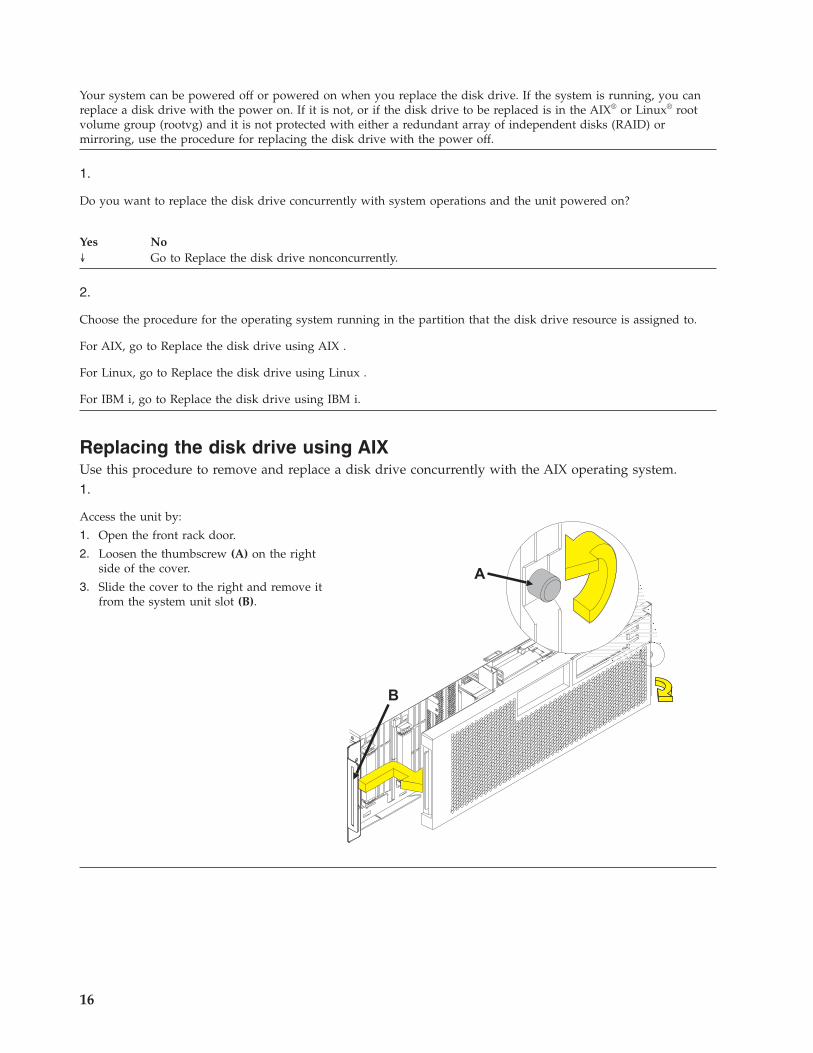
Replacing the disk drive using AIXUse this procedure to remove and replace a disk drive concurrently with the AIX operating system.1.
Access the unit by:
1. Open the front rack door.
2. Loosen the thumbscrew (A) on the rightside of the cover.
3. Slide the cover to the right and remove itfrom the system unit slot (B).
16
2.
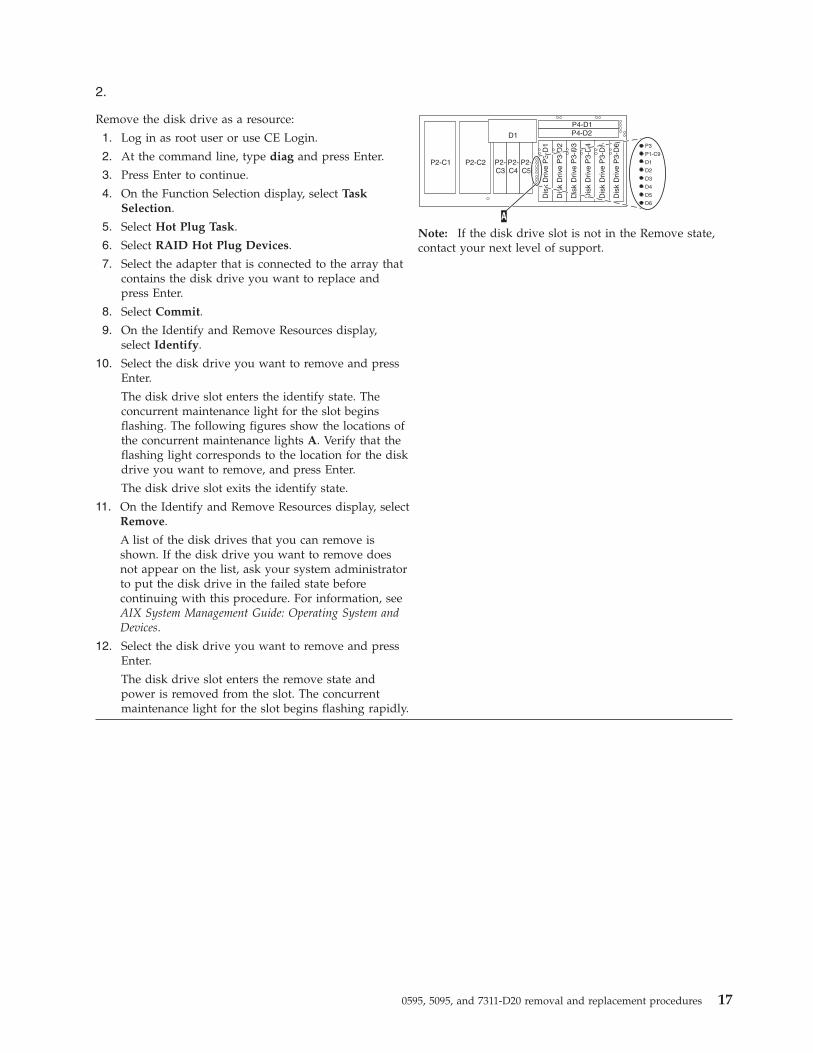
Remove the disk drive as a resource:
1. Log in as root user or use CE Login.
2. At the command line, type diag and press Enter.
3. Press Enter to continue.
4. On the Function Selection display, select TaskSelection.
5. Select Hot Plug Task.
6. Select RAID Hot Plug Devices.
7. Select the adapter that is connected to the array thatcontains the disk drive you want to replace andpress Enter.
8. Select Commit.
9. On the Identify and Remove Resources display,select Identify.
10. Select the disk drive you want to remove and pressEnter.
The disk drive slot enters the identify state. Theconcurrent maintenance light for the slot beginsflashing. The following figures show the locations ofthe concurrent maintenance lights A. Verify that theflashing light corresponds to the location for the diskdrive you want to remove, and press Enter.
The disk drive slot exits the identify state.
11. On the Identify and Remove Resources display, selectRemove.
A list of the disk drives that you can remove isshown. If the disk drive you want to remove doesnot appear on the list, ask your system administratorto put the disk drive in the failed state beforecontinuing with this procedure. For information, seeAIX System Management Guide: Operating System andDevices.
12. Select the disk drive you want to remove and pressEnter.
The disk drive slot enters the remove state andpower is removed from the slot. The concurrentmaintenance light for the slot begins flashing rapidly.
Note: If the disk drive slot is not in the Remove state,contact your next level of support.
0595, 5095, and 7311-D20 removal and replacement procedures 17
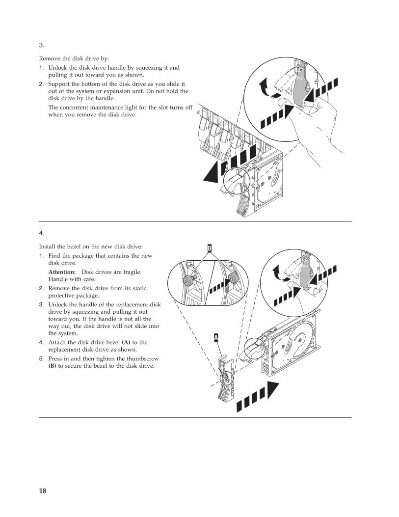
3.
Remove the disk drive by:
1. Unlock the disk drive handle by squeezing it andpulling it out toward you as shown.
2. Support the bottom of the disk drive as you slide itout of the system or expansion unit. Do not hold thedisk drive by the handle.
The concurrent maintenance light for the slot turns offwhen you remove the disk drive.
4.
Install the bezel on the new disk drive:
1. Find the package that contains the newdisk drive.
Attention: Disk drives are fragile.Handle with care.
2. Remove the disk drive from its staticprotective package.
3. Unlock the handle of the replacement diskdrive by squeezing and pulling it outtoward you. If the handle is not all theway out, the disk drive will not slide intothe system.
4. Attach the disk drive bezel (A) to thereplacement disk drive as shown.
5. Press in and then tighten the thumbscrew(B) to secure the bezel to the disk drive.
18
5.
Install the disk drive:
1. Support the bottom of the disk drive as you align it with the guide rails in the system unit. Do not hold the diskdrive by the handle.
2. Slide the disk drive into the system until it stops.
3. Push the disk drive handle in until it locks.Note: It is important to ensure that when installing a disk drive, that the drive is fully seated and all the wayinto the system.
6.
Add the new disk drive as a resource:
1. Press Enter.
The disk drive slot exits the Remove state and enters the Normal state.
2. Exit to the RAID Hot-Plug Devices menu. Press the F3 or ESC 3 key to return
3. Exit to the Task selection display.
4. Select Log Repair Action.
5. Select the disk drive that you replaced and then press Enter.
6. Select Commit after you have made your selection and then press Enter.
7. Exit to the command line.
7.
To rebuild data on the replacement disk drive, refer to the information for the controller to which the disk drive isattached:
v If the disk drive is attached to a PCI-X SCSI RAID controller, see the PCI−X SCSI RAID Controller Reference Guidefor AIX.
v If the disk drive is attached to a PCI SCSI RAID adapter (feature code 2498), see the PCI 4−Channel Ultra3 SCSIRAID Adapter Reference Guide.
For more information, see the AIX System Management Guide: Operating System and Devices.
8. Go to Verifying a repair. This completes this procedure.
Replacing the disk drive using LinuxThis procedure is used to replace a disk drive in a location that is controlled by a system or logicalpartition that is running the Linux operating system.
Preparing to remove the disk drive1. Log in as root user.2. Type iprconfig on the command line of the Linux session and press Enter.
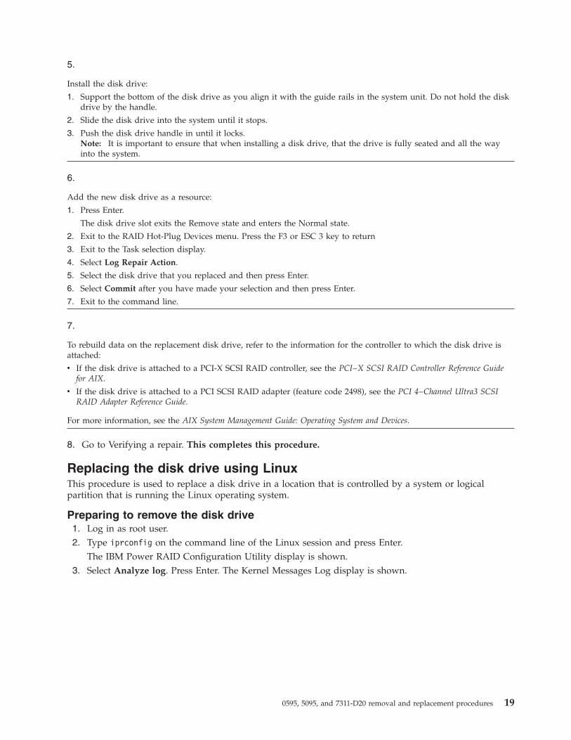
The IBM Power RAID Configuration Utility display is shown.3. Select Analyze log. Press Enter. The Kernel Messages Log display is shown.
0595, 5095, and 7311-D20 removal and replacement procedures 19
4. Select View most recent ipr error messages from the Kernel Messages Log display. Press Enter.5. Find the entry in the log for the disk drive you want to replace.6. Record the location information for the disk drive.
Note: The location information has the form of 2:0:8:0. In this example, 2 is the SCSI host number, 0is the SCSI bus, 8 is the SCSI target ID, and 0 is the LUN (logical unit).
7. Return to the command line.8. Type the following code phrase:
ls -ld /sys/class/scsi_host/host#/device
where # is the SCSI host number. Press Enter.9. Record the PCI location information.
Note: The PCI location information has the form of 61:01:0:2.10. Type iprconfig on the command line and press Enter.
The IBM Power RAID Configuration Utility display is shown.11. Select Display hardware status from the IBM Power RAID Configuration Utility display. Press Enter.
The Display Hardware Status display is shown.
Kernel Messages Log
Select one of the following:
1. View most recent ipr error messages2. View ipr error messages3. View all kernel error messages4. View iprconfig error messages5. Set root kernel message log directory6. Set default editor7. Restore defaults8. View ipr boot time messages
Selection:
e=Exit
Figure 1. Kernel Messages Log
20
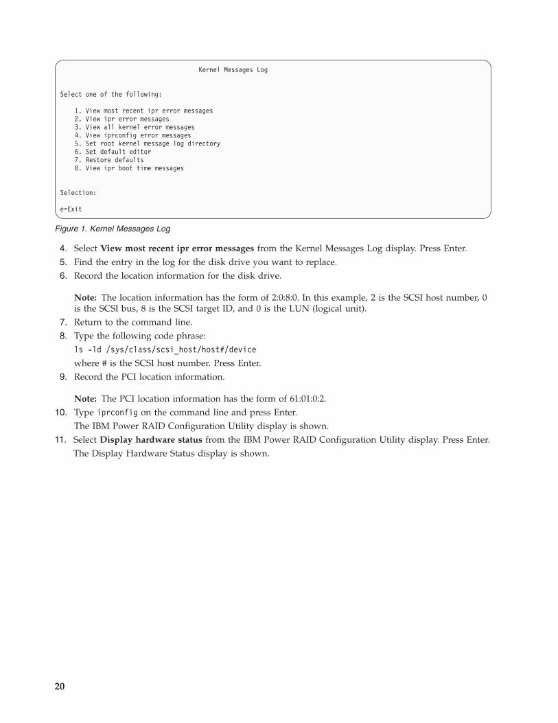
12. Look for the disk drive at the PCI location you recorded. The disk drive might have a failed status.13. If the disk drive you want to replace is unprotected or in use, move the data from the disk drive
before continuing with this procedure.For information, see the PCI-X SCSI RAID Controller Reference Guide for Linux.
14. Type option 1 (Display hardware resource information details) next to the disk drive you want toreplace. Press Enter.A Disk Hardware Resource Information Details display similar to the following is shown.
15. Record the physical location information.16. Return to the IBM Power RAID Configuration Utility display.
Display Hardware Status
Type option, press Enter.1=Display hardware resource information details
OPT Name PCI/SCSI Location Description Status--- ------ -------------------------- ------------------------- ----------------
0000:01:01.0.0/ PCI-X SCSI Adapter Operational0000:41:01.0.1/ PCI-X SCSI Adapter Operational
sda 0000:41:01.0.1/0:3:0 Physical Disk Activesdb 0000:41:01.0.1/0:4:0 Physical Disk Activesdc 0000:41:01.0.1/0:8:0 Physical Disk Activesdd 0000:41:01.0.1/1:3:0 Physical Disk Activesde 0000:41:01.0.1/1:4:0 Physical Disk Activesdf 0000:41:01.0.1/1:5:0 Physical Disk Active
0001:61:01.0.2/ PCI-X SCSI RAID Adapter Operationalsdg 0001:61:01.0.2/0:3:0 Physical Disk Active
0001:61:01.0.2/0:6:0 Advanced Function Disk Activesdi 0001:61:01.0.2/0:9:0 Physical Disk Activesdh 0001:61:01.0.2/255:0:0 RAID 10 Disk Array Failed
0001:61:01.0.2/0:4:0 RAID 10 Array Member Failed0001:61:01.0.2/0:5:0 RAID 10 Array Member Failed
e=Exit q=Cancel r=Refresh t=Toggle
Figure 2. Example Display Hardware Status
Disk Unit Hardware Resource Information Details
Manufacturer . . . . . . . . . . . . . . : IBMProduct ID . . . . . . . . . . . . . . . : ST336607LCFirmware Version . . . . . . . . . . . . : 43353048 (C50H)Serial Number. . . . . . . . . . . . . . : 00006719Capacity . . . . . . . . . . . . . . . . : 36.40 GBResource Name. . . . . . . . . . . . . . : /dev/sdd
Physical locationPCI Address. . . . . . . . . . . . . . . : 0001:50:01.0SCSI Host Number . . . . . . . . . . . . : 2SCSI Channel . . . . . . . . . . . . . . : 0SCSI Id. . . . . . . . . . . . . . . . . : 4SCSI Lun . . . . . . . . . . . . . . . . : 0
Extended DetailsFRU Number . . . . . . . . . . . . . . . : 00P2676
More...Press Enter to Continue
e=Exit q=Cancel f=PageDn b=PageUp
Figure 3. Example Disk Hardware Resource Information Details display
0595, 5095, and 7311-D20 removal and replacement procedures 21

Removing the disk drive1. From the IBM Power RAID Configuration Utility display, select Work with disk unit recovery. Press
Enter.2. From the Work with Disk Unit Recovery display, select Concurrent remove device. Press Enter. A
Concurrent Device Remove display is shown, similar to the following display.
3. Type option 1 (Select) next to the location for the disk drive you want to replace. Press Enter.4. The Verify Device Concurrent Remove display is shown. The concurrent maintenance light turns on
for that disk drive slot.
5. On the Verify Device Concurrent Remove display, verify that the selected disk drive is the disk driveyou want to replace, then press Enter. The identify light turns on for the disk drive.
Note: Ensure that the disk drive is not in use to prevent loss of data.6. The Complete Device Concurrent Remove display is shown.
Attention:
v Attach a wrist strap to an unpainted metal surface of your hardware to prevent electrostaticdischarge (ESD) from damaging your hardware.
v When using a wrist strap, follow all electrical safety procedures. A wrist strap is for static control.It does not increase or decrease your risk of receiving electric shock when using or working onelectrical equipment.
v If you do not have a wrist strap, just prior to removing the product from ESD packaging andinstalling or replacing hardware, touch an unpainted metal surface of the system for a minimumof 5 seconds.
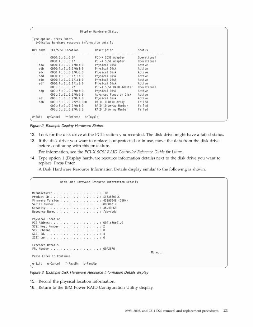
7. Squeeze and pull the handle of the disk drive out toward you before you remove the disk drive asshown in Figure 5 on page 23 or Figure 6 on page 23. If the handle is not all the way out, the disk
Concurrent Device Remove
Choose a single location for remove operations1=Select
OPT Name PCI/SCSI Location Description Status--- ------ -------------------------- ------------------------- -----------------
sdc 0000:41:01.0.1/0:8:0 Physical Disk Active0000:41:01.0.1/0:5: Empty
sdb 0000:41:01.0.1/0:4:0 Physical Disk Activesda 0000:41:01.0.1/0:3:0 Physical Disk Active
0000:41:01.0.1/1:8: Emptysdf 0000:41:01.0.1/1:5:0 Physical Disk Activesde 0000:41:01.0.1/1:4:0 Physical Disk Activesdd 0000:41:01.0.1/1:3:0 Physical Disk Active
0001:61:01.0.2/0:8: Emptysdh 0001:61:01.0.2/0:9:0 Physical Disk Activesdg 0001:61:01.0.2/0:3:0 Physical Disk Active
Figure 4. Example Concurrent Device Remove display
22
drive will not slide out of the system or expansion unit.
8. Support the bottom of the disk drive as you slide it out of the system or expansion unit. Do not holdthe disk drive by the handle.
Figure 5. Removing a disk drive from the system unit
Figure 6. Removing a disk drive from the system unit
0595, 5095, and 7311-D20 removal and replacement procedures 23
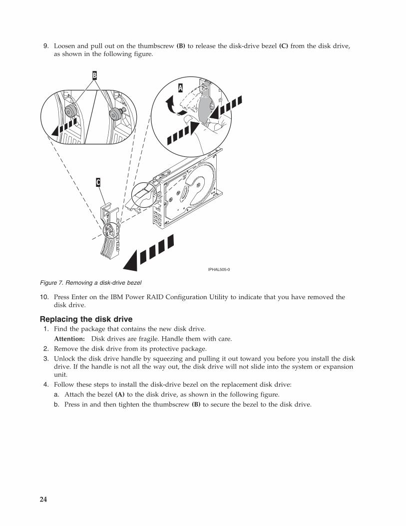
9. Loosen and pull out on the thumbscrew (B) to release the disk-drive bezel (C) from the disk drive,as shown in the following figure.
10. Press Enter on the IBM Power RAID Configuration Utility to indicate that you have removed thedisk drive.
Replacing the disk drive1. Find the package that contains the new disk drive.
Attention: Disk drives are fragile. Handle them with care.2. Remove the disk drive from its protective package.3. Unlock the disk drive handle by squeezing and pulling it out toward you before you install the disk
drive. If the handle is not all the way out, the disk drive will not slide into the system or expansionunit.
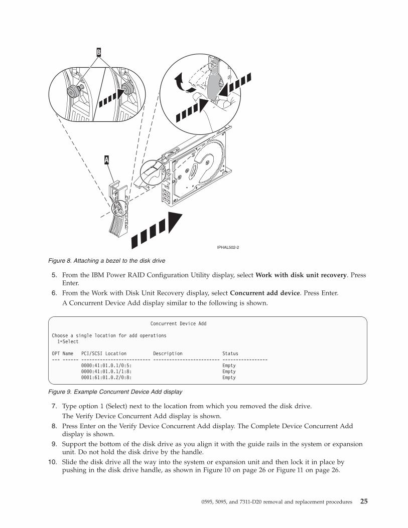
4. Follow these steps to install the disk-drive bezel on the replacement disk drive:a. Attach the bezel (A) to the disk drive, as shown in the following figure.b. Press in and then tighten the thumbscrew (B) to secure the bezel to the disk drive.
Figure 7. Removing a disk-drive bezel
24
5. From the IBM Power RAID Configuration Utility display, select Work with disk unit recovery. PressEnter.
6. From the Work with Disk Unit Recovery display, select Concurrent add device. Press Enter.A Concurrent Device Add display similar to the following is shown.
7. Type option 1 (Select) next to the location from which you removed the disk drive.The Verify Device Concurrent Add display is shown.
8. Press Enter on the Verify Device Concurrent Add display. The Complete Device Concurrent Adddisplay is shown.
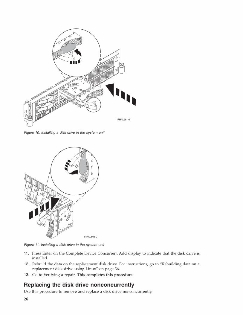
9. Support the bottom of the disk drive as you align it with the guide rails in the system or expansionunit. Do not hold the disk drive by the handle.
10. Slide the disk drive all the way into the system or expansion unit and then lock it in place bypushing in the disk drive handle, as shown in Figure 10 on page 26 or Figure 11 on page 26.
Figure 8. Attaching a bezel to the disk drive
Concurrent Device Add
Choose a single location for add operations1=Select
OPT Name PCI/SCSI Location Description Status--- ------ -------------------------- ------------------------- -----------------
0000:41:01.0.1/0:5: Empty0000:41:01.0.1/1:8: Empty0001:61:01.0.2/0:8: Empty
Figure 9. Example Concurrent Device Add display
0595, 5095, and 7311-D20 removal and replacement procedures 25
11. Press Enter on the Complete Device Concurrent Add display to indicate that the disk drive isinstalled.
12. Rebuild the data on the replacement disk drive. For instructions, go to “Rebuilding data on areplacement disk drive using Linux” on page 36.
13. Go to Verifying a repair. This completes this procedure.
Replacing the disk drive nonconcurrentlyUse this procedure to remove and replace a disk drive nonconcurrently.
Figure 10. Installing a disk drive in the system unit
Figure 11. Installing a disk drive in the system unit
26

1.
The component will not be serviced concurrently. If this system is powered on, power it off before continuing.
When the system is powered off, disconnect the AC input source from the enclosure being serviced. Do not applypower to the enclosure until directed to do so in this procedure.
2.
Access the unit by:
1. Open the front rack door.
2. Loosen the thumbscrew (A) on the rightside of the cover.
3. Slide the cover to the right and remove itfrom the system unit slot (B).
0595, 5095, and 7311-D20 removal and replacement procedures 27
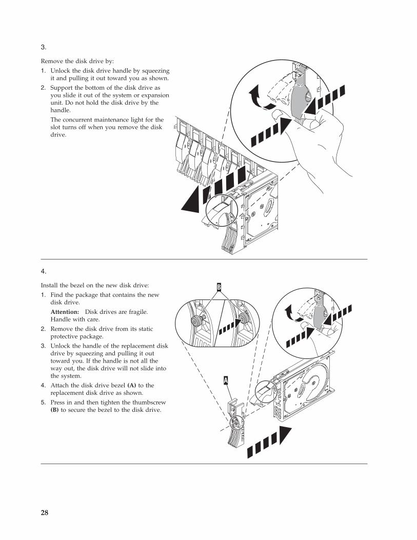
3.
Remove the disk drive by:
1. Unlock the disk drive handle by squeezingit and pulling it out toward you as shown.
2. Support the bottom of the disk drive asyou slide it out of the system or expansionunit. Do not hold the disk drive by thehandle.
The concurrent maintenance light for theslot turns off when you remove the diskdrive.
4.
Install the bezel on the new disk drive:
1. Find the package that contains the newdisk drive.
Attention: Disk drives are fragile.Handle with care.
2. Remove the disk drive from its staticprotective package.
3. Unlock the handle of the replacement diskdrive by squeezing and pulling it outtoward you. If the handle is not all theway out, the disk drive will not slide intothe system.
4. Attach the disk drive bezel (A) to thereplacement disk drive as shown.
5. Press in and then tighten the thumbscrew(B) to secure the bezel to the disk drive.
28
5.
Install the disk drive:
1. Support the bottom of the disk drive as you align it with the guide rails in the system unit. Do not hold the diskdrive by the handle.
2. Slide the disk drive into the system until it stops.
3. Push the disk drive handle in until it locks.Note: It is important to ensure that when installing a disk drive, that the drive is fully seated and all the wayinto the system.
4. Reconnect the power source.
5. Power on the unit, and then go to Verifying a repair. This completes this procedure.
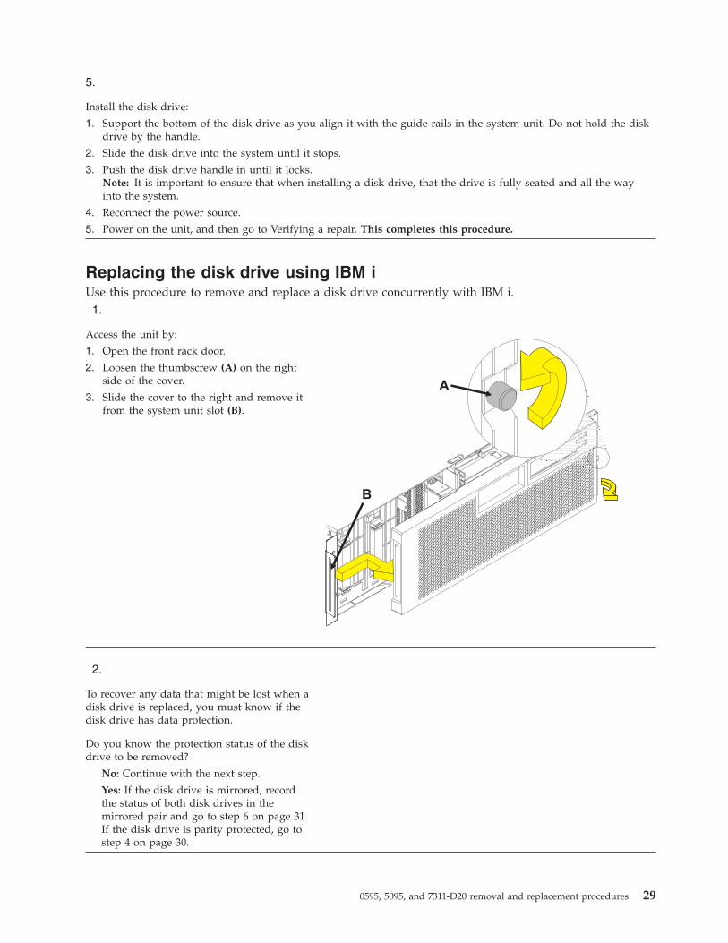
Replacing the disk drive using IBM iUse this procedure to remove and replace a disk drive concurrently with IBM i.1.
Access the unit by:
1. Open the front rack door.
2. Loosen the thumbscrew (A) on the rightside of the cover.
3. Slide the cover to the right and remove itfrom the system unit slot (B).
2.
To recover any data that might be lost when adisk drive is replaced, you must know if thedisk drive has data protection.
Do you know the protection status of the diskdrive to be removed?
No: Continue with the next step.
Yes: If the disk drive is mirrored, recordthe status of both disk drives in themirrored pair and go to step 6 on page 31.If the disk drive is parity protected, go tostep 4 on page 30.
0595, 5095, and 7311-D20 removal and replacement procedures 29
3.
Determine the protection status of the disk drive to beremoved:
1. Sign on the operator console with at least service levelauthority.
2. Type strsst on the command line of the IBM i sessionand press Enter.
3. Type your service tools user ID and service toolspassword on the Start Service Tools (STRSST) Sign Ondisplay. Press Enter.
4. Select Work with disk units from the System ServiceTools (SST) display. Press Enter.
5. Select Display Disk Configuration from the Workwith Disk Units display. Press Enter.
6. Select Display Disk Configuration Status from theDisplay Disk Configuration display. Press Enter.
A list of each auxiliary storage pool (ASP) displays,showing the disk drives that are members of theASPs..
7. Is the status of the failing disk drive Mirrored?
No: Continue with the next step.
Yes: Record the status of both disk drives in themirrored pair and continue at step 6 on page 31.
4.
Determine if the failing disk drive is parity protected:
Check the status of the failing disk drive for one of thefollowing items:
DPY/Active
DPY/Failed
DPY/HDW Failure
DPY/Degraded
DPY/Power Loss
DPY/Not Ready
DPY/Unknown
If the status of the failing disk drive and all other diskdrives in the array is shown in the preceding list, thefailing disk drive is parity protected.
Is the failing disk drive parity protected?
Yes: Go to step 9 on page 32.
No: Continue with the next step.
Note: An ASP with a status of unprotected mightcontain disk drives that are device parity protected.
5.
Perform a backup of the data in the failing ASP.
Go to step 9 on page 32.
Note: This is a customer task. Refer to the system’soperations information for instructions.
30
6.
Does the disk drive you are replacing have a status ofsuspended?
Yes: Go to step 9 on page 32.
No: Check the status of the disk drive that ismirrored to the disk drive you are replacing. If it isSuspended, go to step 8. If it is Active, continue withthe next step.
7.
Suspend the disk drive that you are replacing byperforming the following steps:
1. Press F3 from the Display Disk Configuration displayto return to the Work with Disk Units display.
2. Select Work with Disk Unit Recovery from the Workwith Disk Units display and press Enter.
3. Select Suspend mirrored protection from the Workwith Disk Unit Recovery display and press Enter.
4. Select the option to suspend the disk drive that youare replacing from the Suspend Mirrored Protectiondisplay and press Enter.
5. Go to step 9 on page 32.
8.
The suspended mirrored pair of the failing drive has alsofailed and must be replaced.
Perform a backup of the data in the failing ASP.
Go to step 9 on page 32 to replace the failing mirroreddisk.
Return to the beginning of this procedure to replace thedisk that you originally intended to replace.
Note: Performing a backup is a customer task. Refer tothe system’s operations information for instructions.
0595, 5095, and 7311-D20 removal and replacement procedures 31
9.
Select Device Concurrent Maintenance from theHardware Service Manager display. Press Enter. TheDevice Concurrent Maintenance display is displayed.
1. Enter the location code of the disk drive beingreplaced in the form of: U787A.001.AAAXXXX-P3-D4
2. Select option 1 (Remove device) for the Action to beperformed.
3. Set the time delay for one minute: 01.
Important: Do not press Enter at this time.
4. Locate the concurrent maintenance light thatcorresponds to the position of the disk drive that youare replacing.Important: When you press Enter, after a one minutedelay, this light comes on and begins to blink rapidly.You then have nine seconds to remove the disk drive.
5. Press Enter on the console.
6. When the light blinks rapidly, perform the next stepto remove the disk drive within 9 seconds.
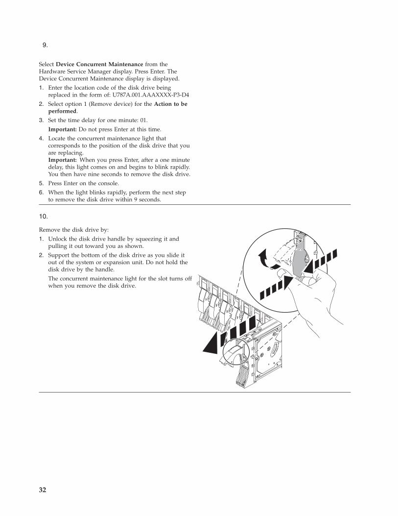
10.
Remove the disk drive by:
1. Unlock the disk drive handle by squeezing it andpulling it out toward you as shown.
2. Support the bottom of the disk drive as you slide itout of the system or expansion unit. Do not hold thedisk drive by the handle.
The concurrent maintenance light for the slot turns offwhen you remove the disk drive.
32
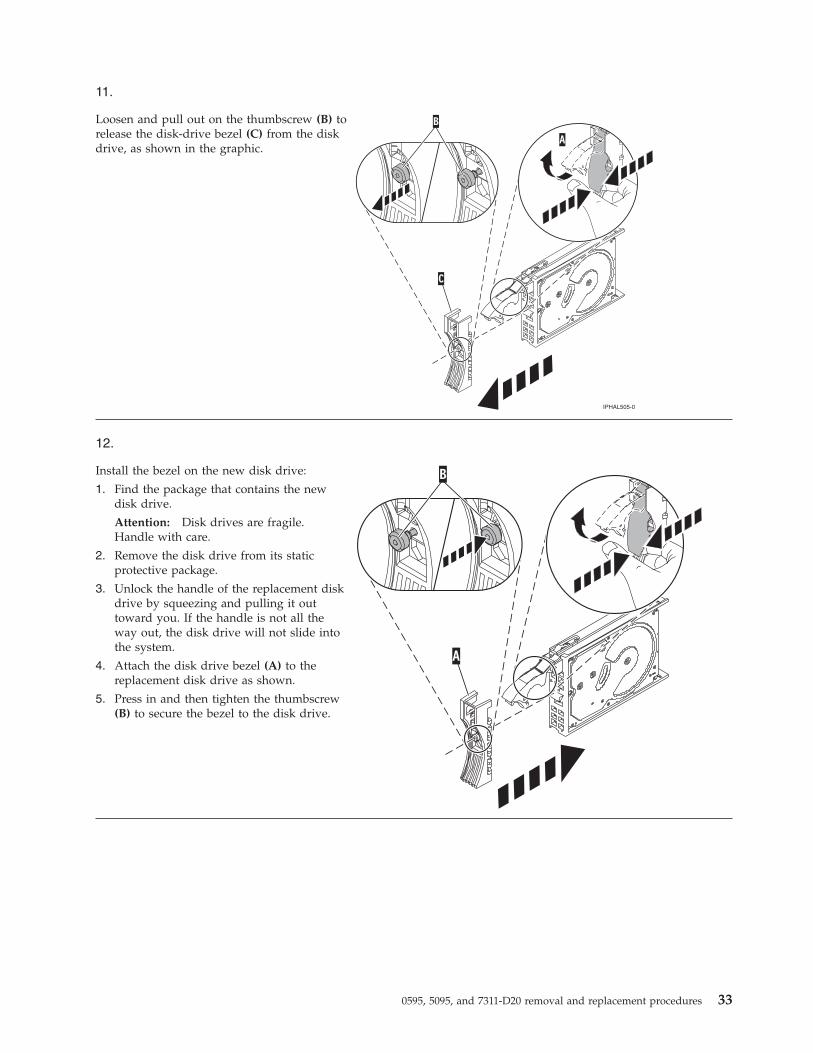
11.
Loosen and pull out on the thumbscrew (B) torelease the disk-drive bezel (C) from the diskdrive, as shown in the graphic.
12.
Install the bezel on the new disk drive:
1. Find the package that contains the newdisk drive.
Attention: Disk drives are fragile.Handle with care.
2. Remove the disk drive from its staticprotective package.
3. Unlock the handle of the replacement diskdrive by squeezing and pulling it outtoward you. If the handle is not all theway out, the disk drive will not slide intothe system.
4. Attach the disk drive bezel (A) to thereplacement disk drive as shown.
5. Press in and then tighten the thumbscrew(B) to secure the bezel to the disk drive.
0595, 5095, and 7311-D20 removal and replacement procedures 33
13.
1. Return to the console and wait until the ConcurrentMaintenance Results display is shown. Press F12.
2. The physical locations you entered in step 6 of thisprocedure might still appear on the display. If not,retype the physical location where you will beinstalling the new disk drive.
3. Select option 2 (Install device) for the Action to beperformed.
4. Set the time delay for one minute: 01.
Important: Do not press Enter at this time.
5. Locate the concurrent maintenance light thatcorresponds to the position of the disk drive that youare replacing
6. Important: When you press Enter, after a one minutedelay, this light comes on and begins to blink rapidly.You then have nine seconds to install the disk drive.
14.
Install the disk drive:
1. Support the bottom of the disk drive as you align it with the guide rails in the system unit. Do not hold the diskdrive by the handle.
2. Slide the disk drive into the system until it stops.
3. Press Enter on the console.
4. When the light blinks rapidly, perform the next step to install the disk drive within 9 seconds.
5. Push the disk drive handle in until it locks.Note: It is important to ensure that the drive is fully seated all the way into the system when installing a diskdrive.
15.
1. If you removed a front cover, install the front cover
2. Install or close the system, expansion unit or rack front door.
3. Return to the console and wait until the Concurrent Maintenance Results display is shown. Press Enter.
4. If you return to the service action log display, exit the service action log.
5. When the Hardware Service Manager display is shown, press F3.
16.
Rebuild the data on the replacement disk drive by:
1. If necessary, start System Service Tools (SST) by typing strsst on the command line of the IBM i session andpressing Enter.
2. Type your service tools user ID and service tools password on the Start Service Tools (STRSST) Sign On display.Press Enter.
Note: The service tools password is case sensitive.
3. Select Work with disk units from the Start System Service Tools (SST) display. Press Enter.
4. Select Work with disk unit recovery from the Work with Disk Units display. Press Enter.
Was the failing disk drive mirrored?
Yes: Go to step 20 on page 35.
No: Continue with the next step.
34

17.
Was the failing disk drive parity protected?
Yes: Go to step 20.
No: Continue with the next step.
18.
Restore the data on the replacement disk drive from the latest backup available.Note: Performing a restore is a customer task. Refer to the system’s operations information for instructions.
19.
1. Select Rebuild disk unit data on the Work with Disk unit recovery display. Press Enter.
2. Select 1 to rebuild the disk drive displayed (the disk drive displayed is the disk drive that you removed) on theRebuild Disk Unit Data display. Press Enter.
3. Press Enter on the Confirm Rebuild Disk Unit Data display. The rebuild process might take several minutes tocomplete.
4. Press F5 to refresh the display until the Percent complete shows 5%.
5. When the display shows at least 5% complete, you can either continue to monitor this display to completion, orpress F3 (Exit) to return to the Work with disk units display.
6. Press F3 (Exit) to return to the System service tools display.
7. Press F3 (Exit) to return to the Exit SST display and press Enter.
20.
1. Select Replace configured unit on the Work with Disk unit recovery display. Press Enter.
2. Select the configured disk drive that you are exchanging (suspended drive) on the Select Configured Unit toReplace display. Press Enter.
3. Select the disk drive that you just installed on the Select Replacement Unit display. This drive has anon-configured status.
Note: In some cases, it might take several minutes for a new disk drive to display. Repeat these steps until thenew drive is shown.
Press Enter.
4. Press Enter on the Confirm Replace of Configured Unit display to confirm your choice for replacement.
The replacement process might take several minutes to complete.
When the process is complete, the Work with Disk unit recovery display is shown.
5. Press F3 (Exit) to return to the Work with disk units display.
6. Select Display disk configuration on the Work with disk units display.
7. Select Display disk configuration status on the Display Disk Configuration display.
Mirrored status shows Resuming. When complete, the mirrored status shows Active. This process might takeseveral minutes to complete. You can either monitor this display to completion, or press F3 (Exit) three times, andthen press Enter to return to the main menu.
Was the failing disk drive mirrored?
Yes: Go to step 22 on page 36.
No: Continue with the next step.
0595, 5095, and 7311-D20 removal and replacement procedures 35
21.
To rebuild data on the replacement disk drive, refer to the information for the controller to which the disk drive isattached:
v If the disk drive is attached to a PCI-X SCSI RAID controller, see the PCI−X SCSI RAID Controller Reference Guidefor AIX.
v If the disk drive is attached to a PCI SCSI RAID adapter (feature code 2498), see the PCI 4−Channel Ultra3 SCSIRAID Adapter Reference Guide.
For more information, see the AIX System Management Guide: Operating System and Devices.
22. Go to Verifying a repair. This completes this procedure.
Rebuilding data on a replacement disk drive using LinuxUse this procedure to rebuild data on a replacement disk drive.
To rebuild data on the replacement disk drive, complete the steps listed here.
For an unprotected disk drive
If the disk drive you are replacing is in a RAID Level 0 disk array or in a failed RAID Level 5 or RAIDLevel 10 disk array, perform these tasks:1. Re-create the disk array.2. Re-create the file systems on the disk array.3. Copy the data back to the restored disk array from your backup media.
For information on these tasks, see the PCI-X SCSI RAID Controller Reference Guide for Linux, SA23-1327.
Display panelUse this procedure to service the display panel.1.
The component will be serviced non-concurrently.
Power should be removed from the unit. If this unit is powered on, power it off now. When the unit is completelypowered off, disconnect the AC input source by removing the power cord from the unit. Do not apply power to theunit until directed to do so in this procedure.
36
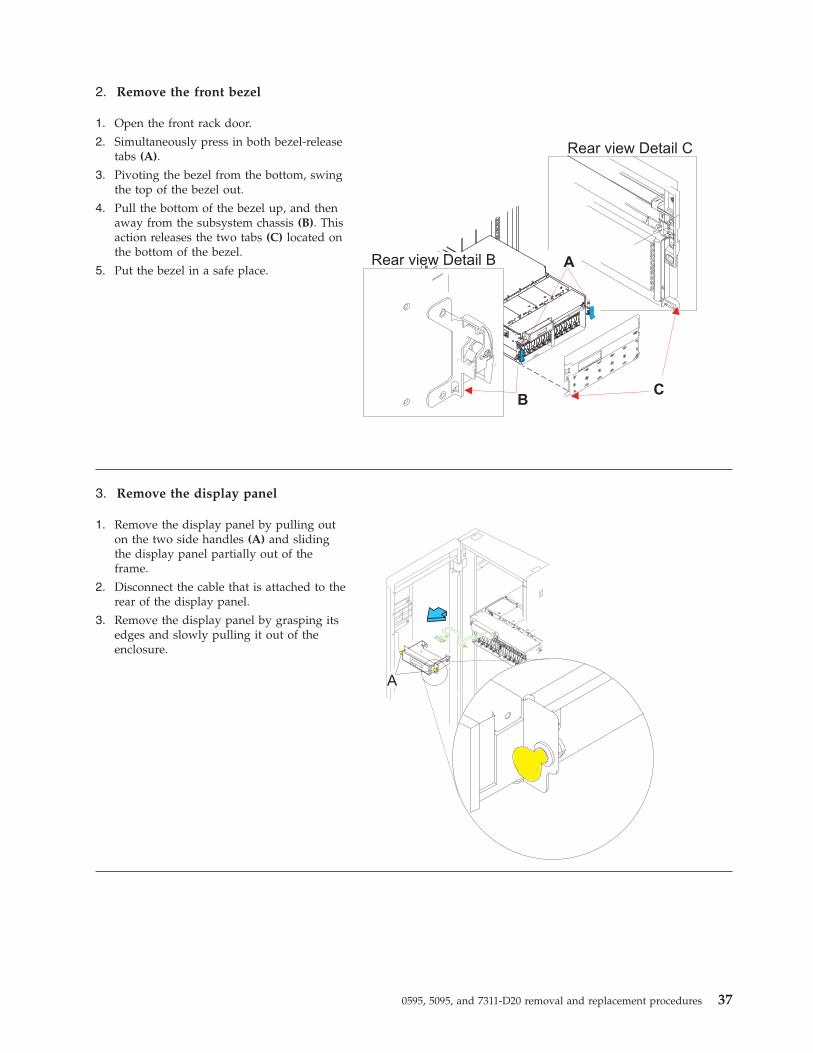
2. Remove the front bezel
1. Open the front rack door.
2. Simultaneously press in both bezel-releasetabs (A).
3. Pivoting the bezel from the bottom, swingthe top of the bezel out.
4. Pull the bottom of the bezel up, and thenaway from the subsystem chassis (B). Thisaction releases the two tabs (C) located onthe bottom of the bezel.
5. Put the bezel in a safe place.
3. Remove the display panel
1. Remove the display panel by pulling outon the two side handles (A) and slidingthe display panel partially out of theframe.
2. Disconnect the cable that is attached to therear of the display panel.
3. Remove the display panel by grasping itsedges and slowly pulling it out of theenclosure.
0595, 5095, and 7311-D20 removal and replacement procedures 37
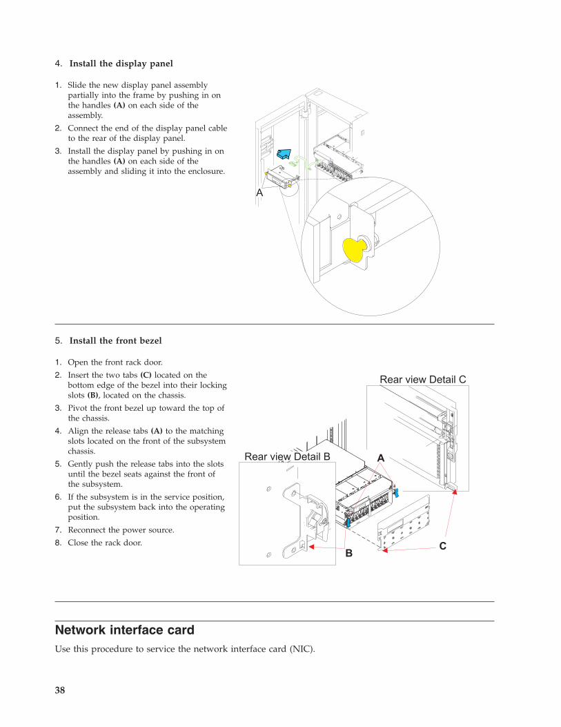
4. Install the display panel
1. Slide the new display panel assemblypartially into the frame by pushing in onthe handles (A) on each side of theassembly.
2. Connect the end of the display panel cableto the rear of the display panel.
3. Install the display panel by pushing in onthe handles (A) on each side of theassembly and sliding it into the enclosure.
5. Install the front bezel
1. Open the front rack door.
2. Insert the two tabs (C) located on thebottom edge of the bezel into their lockingslots (B), located on the chassis.
3. Pivot the front bezel up toward the top ofthe chassis.
4. Align the release tabs (A) to the matchingslots located on the front of the subsystemchassis.
5. Gently push the release tabs into the slotsuntil the bezel seats against the front ofthe subsystem.
6. If the subsystem is in the service position,put the subsystem back into the operatingposition.
7. Reconnect the power source.
8. Close the rack door.
Network interface cardUse this procedure to service the network interface card (NIC).
38
1. This component is serviced nonconcurrently.
Power should be removed from the unit. If this unit is powered on, power it off now. When the unit is completelypowered off, disconnect the AC input source by removing the power cord from the unit. Do not apply power to theunit until directed to do so in this procedure.
2. CAUTION:
The system contains circuit cards and/or assemblies that contain lead solder. To avoid the release of lead (Pb) intothe environment, do not burn. Discard the circuit card as instructed by local regulations. (C014)
Attention: All cards are sensitive to electrostatic discharge.
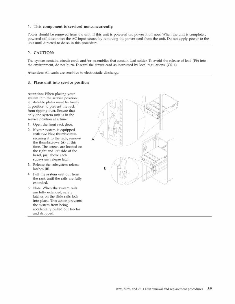
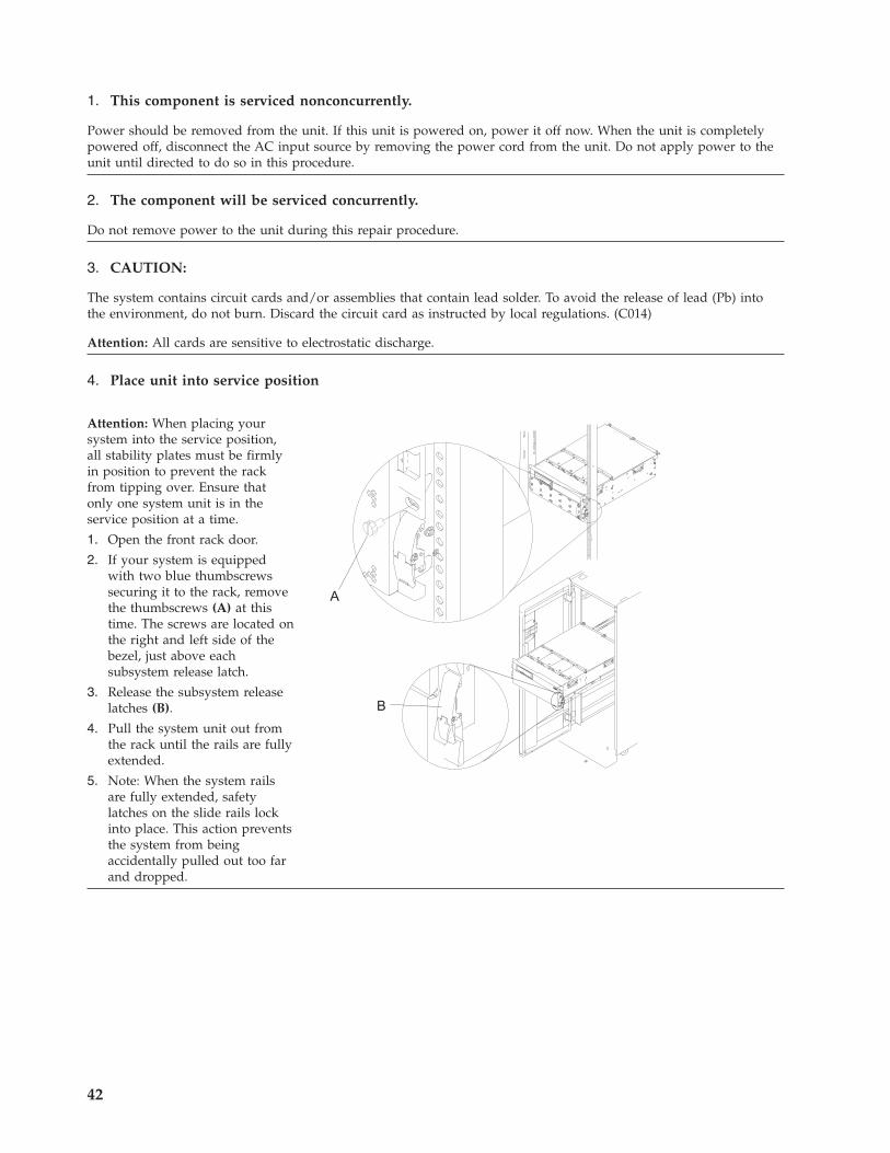
3. Place unit into service position
Attention: When placing yoursystem into the service position,all stability plates must be firmlyin position to prevent the rackfrom tipping over. Ensure thatonly one system unit is in theservice position at a time.
1. Open the front rack door.
2. If your system is equippedwith two blue thumbscrewssecuring it to the rack, removethe thumbscrews (A) at thistime. The screws are located onthe right and left side of thebezel, just above eachsubsystem release latch.
3. Release the subsystem releaselatches (B).
4. Pull the system unit out fromthe rack until the rails are fullyextended.
5. Note: When the system railsare fully extended, safetylatches on the slide rails lockinto place. This action preventsthe system from beingaccidentally pulled out too farand dropped.
0595, 5095, and 7311-D20 removal and replacement procedures 39
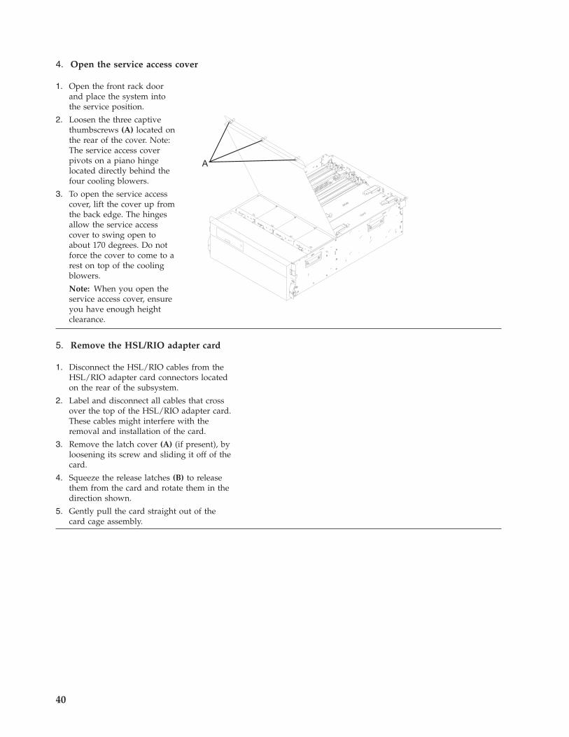
4. Open the service access cover
1. Open the front rack doorand place the system intothe service position.
2. Loosen the three captivethumbscrews (A) located onthe rear of the cover. Note:The service access coverpivots on a piano hingelocated directly behind thefour cooling blowers.
3. To open the service accesscover, lift the cover up fromthe back edge. The hingesallow the service accesscover to swing open toabout 170 degrees. Do notforce the cover to come to arest on top of the coolingblowers.
Note: When you open theservice access cover, ensureyou have enough heightclearance.
5. Remove the HSL/RIO adapter card
1. Disconnect the HSL/RIO cables from theHSL/RIO adapter card connectors locatedon the rear of the subsystem.
2. Label and disconnect all cables that crossover the top of the HSL/RIO adapter card.These cables might interfere with theremoval and installation of the card.
3. Remove the latch cover (A) (if present), byloosening its screw and sliding it off of thecard.
4. Squeeze the release latches (B) to releasethem from the card and rotate them in thedirection shown.
5. Gently pull the card straight out of thecard cage assembly.
40
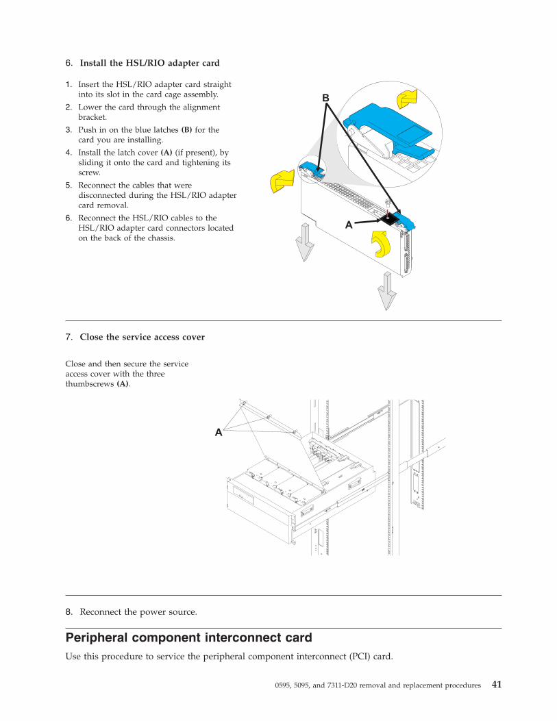
6. Install the HSL/RIO adapter card
1. Insert the HSL/RIO adapter card straightinto its slot in the card cage assembly.
2. Lower the card through the alignmentbracket.
3. Push in on the blue latches (B) for thecard you are installing.
4. Install the latch cover (A) (if present), bysliding it onto the card and tightening itsscrew.
5. Reconnect the cables that weredisconnected during the HSL/RIO adaptercard removal.
6. Reconnect the HSL/RIO cables to theHSL/RIO adapter card connectors locatedon the back of the chassis.
7. Close the service access cover
Close and then secure the serviceaccess cover with the threethumbscrews (A).
8. Reconnect the power source.
Peripheral component interconnect cardUse this procedure to service the peripheral component interconnect (PCI) card.
0595, 5095, and 7311-D20 removal and replacement procedures 41
1. This component is serviced nonconcurrently.
Power should be removed from the unit. If this unit is powered on, power it off now. When the unit is completelypowered off, disconnect the AC input source by removing the power cord from the unit. Do not apply power to theunit until directed to do so in this procedure.
2. The component will be serviced concurrently.
Do not remove power to the unit during this repair procedure.
3. CAUTION:
The system contains circuit cards and/or assemblies that contain lead solder. To avoid the release of lead (Pb) intothe environment, do not burn. Discard the circuit card as instructed by local regulations. (C014)
Attention: All cards are sensitive to electrostatic discharge.
4. Place unit into service position
Attention: When placing yoursystem into the service position,all stability plates must be firmlyin position to prevent the rackfrom tipping over. Ensure thatonly one system unit is in theservice position at a time.
1. Open the front rack door.
2. If your system is equippedwith two blue thumbscrewssecuring it to the rack, removethe thumbscrews (A) at thistime. The screws are located onthe right and left side of thebezel, just above eachsubsystem release latch.
3. Release the subsystem releaselatches (B).
4. Pull the system unit out fromthe rack until the rails are fullyextended.
5. Note: When the system railsare fully extended, safetylatches on the slide rails lockinto place. This action preventsthe system from beingaccidentally pulled out too farand dropped.
42
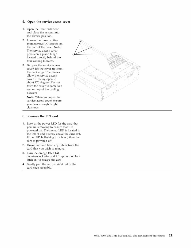
5. Open the service access cover
1. Open the front rack doorand place the system intothe service position.
2. Loosen the three captivethumbscrews (A) located onthe rear of the cover. Note:The service access coverpivots on a piano hingelocated directly behind thefour cooling blowers.
3. To open the service accesscover, lift the cover up fromthe back edge. The hingesallow the service accesscover to swing open toabout 170 degrees. Do notforce the cover to come to arest on top of the coolingblowers.
Note: When you open theservice access cover, ensureyou have enough heightclearance.
6. Remove the PCI card
1. Look at the power LED for the card thatyou are removing to ensure that it ispowered off. The power LED is located tothe left of and directly above the card slot.If the LED is flashing or it is off, then thecard is powered off.
2. Disconnect and label any cables from thecard that you wish to remove.
3. Turn the orange latch (A)counter-clockwise and lift up on the blacklatch (B) to release the card.
4. Gently pull the card straight out of thecard cage assembly.
0595, 5095, and 7311-D20 removal and replacement procedures 43
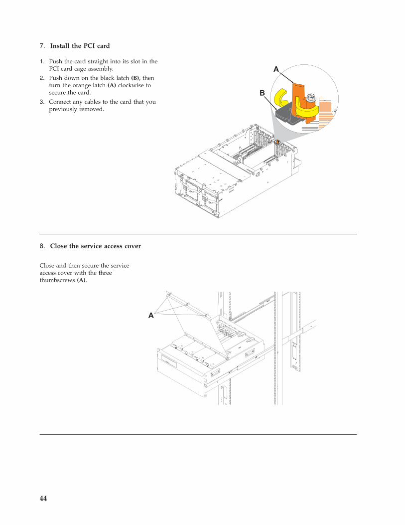
7. Install the PCI card
1. Push the card straight into its slot in thePCI card cage assembly.
2. Push down on the black latch (B), thenturn the orange latch (A) clockwise tosecure the card.
3. Connect any cables to the card that youpreviously removed.
8. Close the service access cover
Close and then secure the serviceaccess cover with the threethumbscrews (A).
44
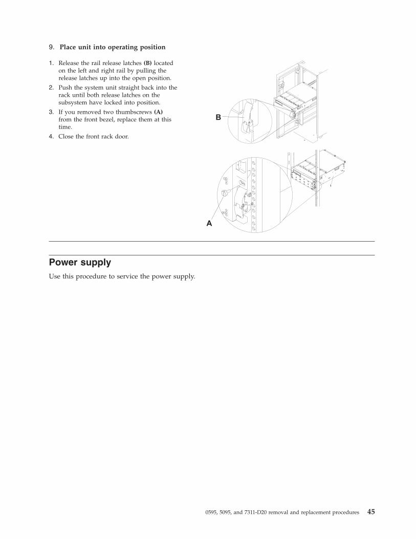
9. Place unit into operating position
1. Release the rail release latches (B) locatedon the left and right rail by pulling therelease latches up into the open position.
2. Push the system unit straight back into therack until both release latches on thesubsystem have locked into position.
3. If you removed two thumbscrews (A)from the front bezel, replace them at thistime.
4. Close the front rack door.
Power supplyUse this procedure to service the power supply.
0595, 5095, and 7311-D20 removal and replacement procedures 45

1. Place unit into service position
Attention: When placing yoursystem into the service position,all stability plates must be firmlyin position to prevent the rackfrom tipping over. Ensure thatonly one system unit is in theservice position at a time.
1. Open the front rack door.
2. If your system is equippedwith two blue thumbscrewssecuring it to the rack, removethe thumbscrews (A) at thistime. The screws are located onthe right and left side of thebezel, just above eachsubsystem release latch.
3. Release the subsystem releaselatches (B).
4. Pull the system unit out fromthe rack until the rails are fullyextended.
5. Note: When the system railsare fully extended, safetylatches on the slide rails lockinto place. This action preventsthe system from beingaccidentally pulled out too farand dropped.
2. Open the service access cover
1. Open the front rack doorand place the system intothe service position.
2. Loosen the three captivethumbscrews (A) located onthe rear of the cover. Note:The service access coverpivots on a piano hingelocated directly behind thefour cooling blowers.
3. To open the service accesscover, lift the cover up fromthe back edge. The hingesallow the service accesscover to swing open toabout 170 degrees. Do notforce the cover to come to arest on top of the coolingblowers.
Note: When you open theservice access cover, ensureyou have enough heightclearance.
46
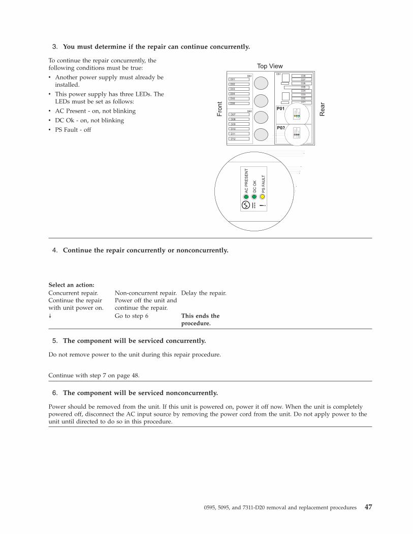
3. You must determine if the repair can continue concurrently.
To continue the repair concurrently, thefollowing conditions must be true:
v Another power supply must already beinstalled.
v This power supply has three LEDs. TheLEDs must be set as follows:
v AC Present - on, not blinking
v DC Ok - on, not blinking
v PS Fault - off
4. Continue the repair concurrently or nonconcurrently.
Select an action:Concurrent repair.Continue the repairwith unit power on.
Non-concurrent repair.Power off the unit andcontinue the repair.
Delay the repair.
↓ Go to step 6 This ends theprocedure.
5. The component will be serviced concurrently.
Do not remove power to the unit during this repair procedure.
Continue with step 7 on page 48.
6. The component will be serviced nonconcurrently.
Power should be removed from the unit. If this unit is powered on, power it off now. When the unit is completelypowered off, disconnect the AC input source by removing the power cord from the unit. Do not apply power to theunit until directed to do so in this procedure.
0595, 5095, and 7311-D20 removal and replacement procedures 47
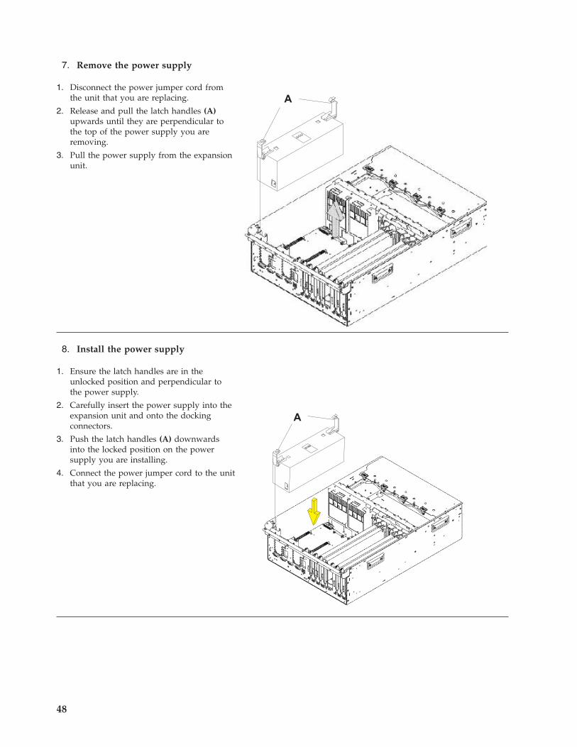
7. Remove the power supply
1. Disconnect the power jumper cord fromthe unit that you are replacing.
2. Release and pull the latch handles (A)upwards until they are perpendicular tothe top of the power supply you areremoving.
3. Pull the power supply from the expansionunit.
8. Install the power supply
1. Ensure the latch handles are in theunlocked position and perpendicular tothe power supply.
2. Carefully insert the power supply into theexpansion unit and onto the dockingconnectors.
3. Push the latch handles (A) downwardsinto the locked position on the powersupply you are installing.
4. Connect the power jumper cord to the unitthat you are replacing.
48
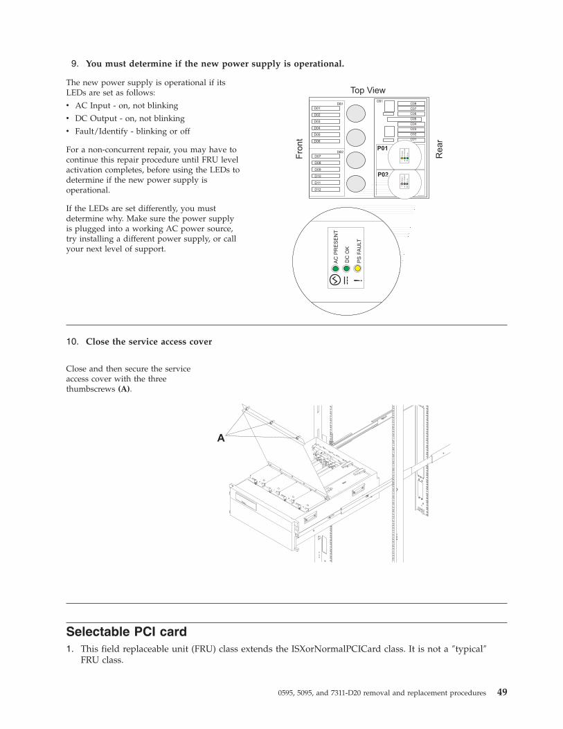
9. You must determine if the new power supply is operational.
The new power supply is operational if itsLEDs are set as follows:
v AC Input - on, not blinking
v DC Output - on, not blinking
v Fault/Identify - blinking or off
For a non-concurrent repair, you may have tocontinue this repair procedure until FRU levelactivation completes, before using the LEDs todetermine if the new power supply isoperational.
If the LEDs are set differently, you mustdetermine why. Make sure the power supplyis plugged into a working AC power source,try installing a different power supply, or callyour next level of support.
10. Close the service access cover
Close and then secure the serviceaccess cover with the threethumbscrews (A).
Selectable PCI card1. This field replaceable unit (FRU) class extends the ISXorNormalPCICard class. It is not a ″typical″
FRU class.
0595, 5095, and 7311-D20 removal and replacement procedures 49
I/O backplaneUse this procedure to service a 0595, 5095, or 7311-D20 I/O backplane.1. Record the activated firmware level of the server for use in this procedure. The activated firmware
level of the server can be found in the upper-right corner of the ASMI utility.2. If this is a 7311-D20 expansion unit connected to a System p® server with an activated firmware level
that is earlier than SF235, the partitions that own slots in the expansion unit must be powered offduring this procedure. Power the partitions off now. This power-off action can be accomplished bypowering off individual partitions, or powering off the server.
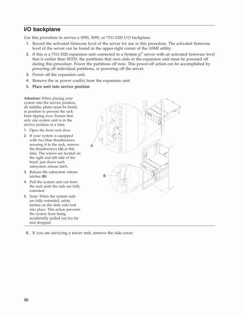
3. Power off the expansion unit.4. Remove the ac power cord(s) from the expansion unit.5. Place unit into service position
Attention: When placing yoursystem into the service position,all stability plates must be firmlyin position to prevent the rackfrom tipping over. Ensure thatonly one system unit is in theservice position at a time.
1. Open the front rack door.
2. If your system is equippedwith two blue thumbscrewssecuring it to the rack, removethe thumbscrews (A) at thistime. The screws are located onthe right and left side of thebezel, just above eachsubsystem release latch.
3. Release the subsystem releaselatches (B).
4. Pull the system unit out fromthe rack until the rails are fullyextended.
5. Note: When the system railsare fully extended, safetylatches on the slide rails lockinto place. This action preventsthe system from beingaccidentally pulled out too farand dropped.
6. If you are servicing a tower unit, remove the side cover.
50
7. Open the service access cover
1. Open the front rack doorand place the system intothe service position.
2. Loosen the three captivethumbscrews (A) located onthe rear of the cover. Note:The service access coverpivots on a piano hingelocated directly behind thefour cooling blowers.
3. To open the service accesscover, lift the cover up fromthe back edge. The hingesallow the service accesscover to swing open toabout 170 degrees. Do notforce the cover to come to arest on top of the coolingblowers.
Note: When you open theservice access cover, ensureyou have enough heightclearance.
8. Remove the following:v PCI cards (see “Peripheral component interconnect card” on page 41)v RIO/HSL I/O bridge adapterv Card dividers
9. Remove the power supplies (see “Power supply” on page 45).10. Remove the five screws (three from the side and two from the back) that hold the backplane to the
expansion unit. Notice the aligning pins near the top of the board, and the power connections nearthe bottom of the board, for use later when you reinstall the board.
11. Install the new backplane by reversing the procedure described in step 5 on page 50 to step 10.12. Reconnect the power cord(s) and/or the power supply cords that you disconnected earlier.
Note: If the server is powered on, the expansion unit will power on automatically.13. Set the I/O enclosure configuration ID and MTMS value, and then continue with the next step of
this procedure.
Note: If this is a 7311-D20 expansion unit that is connected to a System p server that has anactivated firmware level lower than SF235, and if the server is currently powered off, then it must bepowered on to the firmware standby setting, not firmware running, when you are instructed topower on the server in the Setting expansion unit configuration ID and MTMS value dialog.
14. If this is a 7311-D20 expansion unit connected to a System p server with an activated firmware levelthat is lower than SF235, go to step 15. Otherwise, go to step 17 on page 52.
15. If the server is HMC-managed, disconnect one of the SPCN cables from the expansion unit (only oneof them). Wait 30 seconds, then reconnect it. For a server that is not managed by an HMC, this stepcan be omitted.
16. An SPCN microcode download to the expansion unit may or may not be occurring.v If an SPCN microcode download does not occur, go to step 17 on page 52.
0595, 5095, and 7311-D20 removal and replacement procedures 51

v If an SPCN microcode download does occur, wait for the download to finish. Then power theserver off and back on again. Partitions may be started at this time. Then go to step 17.
v There are two ways to determine if an SPCN download is occurring:– Look at the Error/Event Logs using the ASMI utility
- Expand System Service Aids.- Select Error/Event Logs.- A 1xxx9107 SRC in the informational logs section indicates that an SPCN download was
started.- A 1xxx91DD SRC in the informational logs section indicates that an SPCN download
completed.– Look at the expansion unit rack address using the ASMI utility.
- Expand System Configuration.- Select Configure I/O Enclosures.- If the rack address for the expansion unit is a 1-byte value, an SPCN download is occurring.- If the rack address is a 2-byte value, the SPCN download has completed or is not needed.
17. Go to Verifying a repair.This ends the procedure.
52
Appendix. Notices
This information was developed for products and services offered in the U.S.A.
The manufacturer may not offer the products, services, or features discussed in this document in othercountries. Consult the manufacturer’s representative for information on the products and servicescurrently available in your area. Any reference to the manufacturer’s product, program, or service is notintended to state or imply that only that product, program, or service may be used. Any functionallyequivalent product, program, or service that does not infringe any intellectual property right of themanufacturer may be used instead. However, it is the user’s responsibility to evaluate and verify theoperation of any product, program, or service.
The manufacturer may have patents or pending patent applications covering subject matter described inthis document. The furnishing of this document does not grant you any license to these patents. You cansend license inquiries, in writing, to the manufacturer.
The following paragraph does not apply to the United Kingdom or any other country where suchprovisions are inconsistent with local law: THIS INFORMATION IS PROVIDED “AS IS” WITHOUTWARRANTY OF ANY KIND, EITHER EXPRESS OR IMPLIED, INCLUDING, BUT NOT LIMITED TO,THE IMPLIED WARRANTIES OF NON-INFRINGEMENT, MERCHANTABILITY OR FITNESS FOR APARTICULAR PURPOSE. Some states do not allow disclaimer of express or implied warranties in certaintransactions, therefore, this statement may not apply to you.
This information could include technical inaccuracies or typographical errors. Changes are periodicallymade to the information herein; these changes will be incorporated in new editions of the publication.The manufacturer may make improvements and/or changes in the product(s) and/or the program(s)described in this publication at any time without notice.
Any references in this information to Web sites not owned by the manufacturer are provided forconvenience only and do not in any manner serve as an endorsement of those Web sites. The materials atthose Web sites are not part of the materials for this product and use of those Web sites is at your ownrisk.
The manufacturer may use or distribute any of the information you supply in any way it believesappropriate without incurring any obligation to you.
Any performance data contained herein was determined in a controlled environment. Therefore, theresults obtained in other operating environments may vary significantly. Some measurements may havebeen made on development-level systems and there is no guarantee that these measurements will be thesame on generally available systems. Furthermore, some measurements may have been estimated throughextrapolation. Actual results may vary. Users of this document should verify the applicable data for theirspecific environment.
Information concerning products not produced by this manufacturer was obtained from the suppliers ofthose products, their published announcements or other publicly available sources. This manufacturer hasnot tested those products and cannot confirm the accuracy of performance, compatibility or any otherclaims related to products not produced by this manufacturer. Questions on the capabilities of productsnot produced by this manufacturer should be addressed to the suppliers of those products.
All statements regarding the manufacturer’s future direction or intent are subject to change or withdrawalwithout notice, and represent goals and objectives only.
© Copyright IBM Corp. 2008, 2009 53
The manufacturer’s prices shown are the manufacturer’s suggested retail prices, are current and aresubject to change without notice. Dealer prices may vary.
This information is for planning purposes only. The information herein is subject to change before theproducts described become available.
This information contains examples of data and reports used in daily business operations. To illustratethem as completely as possible, the examples include the names of individuals, companies, brands, andproducts. All of these names are fictitious and any similarity to the names and addresses used by anactual business enterprise is entirely coincidental.
If you are viewing this information in softcopy, the photographs and color illustrations may not appear.
The drawings and specifications contained herein shall not be reproduced in whole or in part without thewritten permission of the manufacturer.
The manufacturer has prepared this information for use with the specific machines indicated. Themanufacturer makes no representations that it is suitable for any other purpose.
The manufacturer’s computer systems contain mechanisms designed to reduce the possibility ofundetected data corruption or loss. This risk, however, cannot be eliminated. Users who experienceunplanned outages, system failures, power fluctuations or outages, or component failures must verify theaccuracy of operations performed and data saved or transmitted by the system at or near the time of theoutage or failure. In addition, users must establish procedures to ensure that there is independent dataverification before relying on such data in sensitive or critical operations. Users should periodically checkthe manufacturer’s support websites for updated information and fixes applicable to the system andrelated software.
TrademarksIBM, the IBM logo, and ibm.com are trademarks or registered trademarks of International BusinessMachines Corp., registered in many jurisdictions worldwide. Other product and service names might betrademarks of IBM or other companies. A current list of IBM trademarks is available on the Web atCopyright and trademark information at www.ibm.com/legal/copytrade.shtml.
Linux is a registered trademark of Linus Torvalds in the United States, other countries, or both.
Other company, product, or service names may be trademarks or service marks of others.
Electronic emission notices
Class A NoticesThe following Class A statements apply to the IBM servers that contain the POWER6 processor.
Federal Communications Commission (FCC) statement
Note: This equipment has been tested and found to comply with the limits for a Class A digital device,pursuant to Part 15 of the FCC Rules. These limits are designed to provide reasonable protection againstharmful interference when the equipment is operated in a commercial environment. This equipmentgenerates, uses, and can radiate radio frequency energy and, if not installed and used in accordance withthe instruction manual, may cause harmful interference to radio communications. Operation of thisequipment in a residential area is likely to cause harmful interference, in which case the user will berequired to correct the interference at his own expense.
54
Properly shielded and grounded cables and connectors must be used in order to meet FCC emissionlimits. IBM is not responsible for any radio or television interference caused by using other thanrecommended cables and connectors or by unauthorized changes or modifications to this equipment.Unauthorized changes or modifications could void the user’s authority to operate the equipment.
This device complies with Part 15 of the FCC rules. Operation is subject to the following two conditions:(1) this device may not cause harmful interference, and (2) this device must accept any interferencereceived, including interference that may cause undesired operation.
Industry Canada Compliance Statement
This Class A digital apparatus complies with Canadian ICES-003.
Avis de conformité à la réglementation d’Industrie Canada
Cet appareil numérique de la classe A respecte est conforme à la norme NMB-003 du Canada.
European Community Compliance Statement
This product is in conformity with the protection requirements of EU Council Directive 2004/108/EC onthe approximation of the laws of the Member States relating to electromagnetic compatibility. IBM cannotaccept responsibility for any failure to satisfy the protection requirements resulting from anon-recommended modification of the product, including the fitting of non-IBM option cards.
This product has been tested and found to comply with the limits for Class A Information TechnologyEquipment according to European Standard EN 55022. The limits for Class A equipment were derived forcommercial and industrial environments to provide reasonable protection against interference withlicensed communication equipment.
European Community contact:IBM Technical RegulationsPascalstr. 100, Stuttgart, Germany 70569Tele: 0049 (0)711 785 1176Fax: 0049 (0)711 785 1283E-mail: [email protected]
Warning: This is a Class A product. In a domestic environment, this product may cause radiointerference, in which case the user may be required to take adequate measures.
VCCI Statement - Japan
The following is a summary of the VCCI Japanese statement in the box above:
This is a Class A product based on the standard of the VCCI Council. If this equipment is used in adomestic environment, radio interference may occur, in which case, the user may be required to takecorrective actions.
Appendix. Notices 55
Japanese Electronics and Information Technology Industries Association (JEITA)Confirmed Harmonics Guideline (products less than or equal to 20 A per phase)
Japanese Electronics and Information Technology Industries Association (JEITA)Confirmed Harmonics Guideline with Modifications (products greater than 20 A perphase)
Electromagnetic Interference (EMI) Statement - People’s Republic of China
Declaration: This is a Class A product. In a domestic environment this product may cause radiointerference in which case the user may need to perform practical action.
Electromagnetic Interference (EMI) Statement - Taiwan
The following is a summary of the EMI Taiwan statement above.
Warning: This is a Class A product. In a domestic environment this product may cause radio interferencein which case the user will be required to take adequate measures.
IBM Taiwan Contact Information:
56

Electromagnetic Interference (EMI) Statement - Korea
Please note that this equipment has obtained EMC registration for commercial use. In the event that ithas been mistakenly sold or purchased, please exchange it for equipment certified for home use.
Germany Compliance Statement
Deutschsprachiger EU Hinweis: Hinweis für Geräte der Klasse A EU-Richtlinie zurElektromagnetischen Verträglichkeit
Dieses Produkt entspricht den Schutzanforderungen der EU-Richtlinie 2004/108/EG zur Angleichung derRechtsvorschriften über die elektromagnetische Verträglichkeit in den EU-Mitgliedsstaaten und hält dieGrenzwerte der EN 55022 Klasse A ein.
Um dieses sicherzustellen, sind die Geräte wie in den Handbüchern beschrieben zu installieren und zubetreiben. Des Weiteren dürfen auch nur von der IBM empfohlene Kabel angeschlossen werden. IBMübernimmt keine Verantwortung für die Einhaltung der Schutzanforderungen, wenn das Produkt ohneZustimmung der IBM verändert bzw. wenn Erweiterungskomponenten von Fremdherstellern ohneEmpfehlung der IBM gesteckt/eingebaut werden.
EN 55022 Klasse A Geräte müssen mit folgendem Warnhinweis versehen werden:″Warnung: Dieses ist eine Einrichtung der Klasse A. Diese Einrichtung kann im WohnbereichFunk-Störungen verursachen; in diesem Fall kann vom Betreiber verlangt werden, angemesseneMaßnahmen zu ergreifen und dafür aufzukommen.″
Deutschland: Einhaltung des Gesetzes über die elektromagnetische Verträglichkeit von Geräten
Dieses Produkt entspricht dem “Gesetz über die elektromagnetische Verträglichkeit von Geräten(EMVG)“. Dies ist die Umsetzung der EU-Richtlinie 2004/108/EG in der Bundesrepublik Deutschland.
Zulassungsbescheinigung laut dem Deutschen Gesetz über die elektromagnetische Verträglichkeit vonGeräten (EMVG) (bzw. der EMC EG Richtlinie 2004/108/EG) für Geräte der Klasse A.
Dieses Gerät ist berechtigt, in Übereinstimmung mit dem Deutschen EMVG das EG-Konformitätszeichen- CE - zu führen.
Verantwortlich für die Konformitätserklärung nach des EMVG ist die IBM Deutschland GmbH, 70548Stuttgart.
Appendix. Notices 57
Generelle Informationen:
Das Gerät erfüllt die Schutzanforderungen nach EN 55024 und EN 55022 Klasse A.
Electromagnetic Interference (EMI) Statement - Russia
Terms and conditionsPermissions for the use of these publications is granted subject to the following terms and conditions.
Personal Use: You may reproduce these publications for your personal, noncommercial use provided thatall proprietary notices are preserved. You may not distribute, display or make derivative works of thesepublications, or any portion thereof, without the express consent of the manufacturer.
Commercial Use: You may reproduce, distribute and display these publications solely within yourenterprise provided that all proprietary notices are preserved. You may not make derivative works ofthese publications, or reproduce, distribute or display these publications or any portion thereof outsideyour enterprise, without the express consent of the manufacturer.
Except as expressly granted in this permission, no other permissions, licenses or rights are granted, eitherexpress or implied, to the publications or any data, software or other intellectual property containedtherein.
The manufacturer reserves the right to withdraw the permissions granted herein whenever, in itsdiscretion, the use of the publications is detrimental to its interest or, as determined by the manufacturer,the above instructions are not being properly followed.
You may not download, export or re-export this information except in full compliance with all applicablelaws and regulations, including all United States export laws and regulations.
THE MANUFACTURER MAKES NO GUARANTEE ABOUT THE CONTENT OF THESEPUBLICATIONS. THESE PUBLICATIONS ARE PROVIDED ″AS-IS″ AND WITHOUT WARRANTY OFANY KIND, EITHER EXPRESSED OR IMPLIED, INCLUDING BUT NOT LIMITED TO IMPLIEDWARRANTIES OF MERCHANTABILITY, NON-INFRINGEMENT, AND FITNESS FOR A PARTICULARPURPOSE.
58


����
Printed in USA