power trim square motor and round motor...
TRANSCRIPT
B5
MID-SECTION
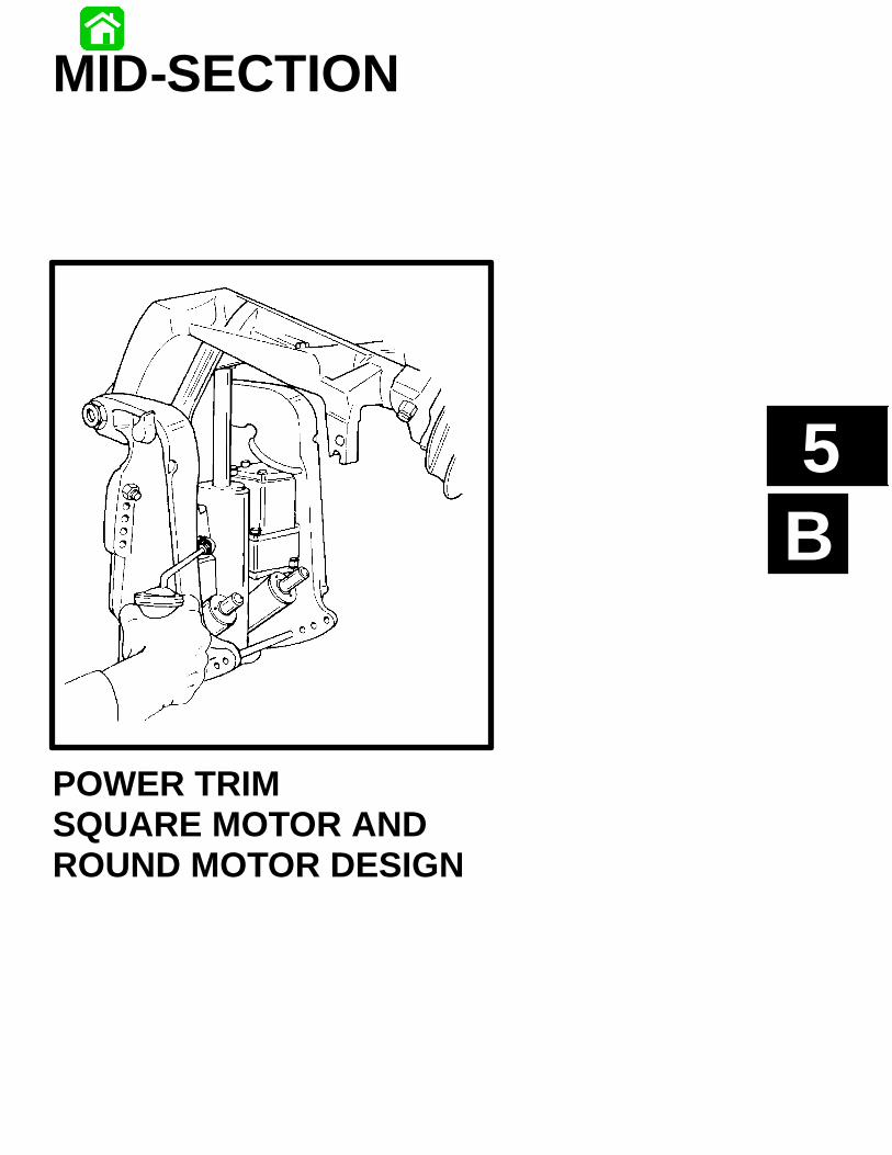
POWER TRIMSQUARE MOTOR ANDROUND MOTOR DESIGN

5B-0 - MID-SECTION 90-822900R3 DECEMBER 1997
Table of ContentsPage
Power Trim Specifications 5B-1. . . . . . . . . . . . . . . . . . . . .Special Tools 5B-1. . . . . . . . . . . . . . . . . . . . . . . . . . . . . . . .Power Trim Components (Square Motor) 5B-2. . . . . . . .Power Trim Motor 5B-4. . . . . . . . . . . . . . . . . . . . . . . . . . . .Notes: 5B-5. . . . . . . . . . . . . . . . . . . . . . . . . . . . . . . . . . . . . .Power Trim Components (Round Motor) 5B-6. . . . . . . . .3 Ram Power Trim (External Mounted - Aft Fill)Hydraulic System 5B-8. . . . . . . . . . . . . . . . . . . . . . . . . . . . .
Trim Up 5B-8. . . . . . . . . . . . . . . . . . . . . . . . . . . . . . . . . .Hydraulic Tilt 5B-9. . . . . . . . . . . . . . . . . . . . . . . . . . . . . .UP Circuit 5B-9. . . . . . . . . . . . . . . . . . . . . . . . . . . . . . . .
3 Ram Power Trim Hydraulic System 5B-10. . . . . . . . . . .Trim Down 5B-10. . . . . . . . . . . . . . . . . . . . . . . . . . . . . . .Down Circuit 5B-10. . . . . . . . . . . . . . . . . . . . . . . . . . . . .
3 Ram Power Trim Hydraulic System 5B-11. . . . . . . . . . .Bounce and Shock Absorber 5B-11. . . . . . . . . . . . . . .Bounce System 5B-11. . . . . . . . . . . . . . . . . . . . . . . . . .Shock System 5B-11. . . . . . . . . . . . . . . . . . . . . . . . . . . .
3 Ram Power Trim Hydraulic System 5B-12. . . . . . . . . . .Manual Tilt 5B-12. . . . . . . . . . . . . . . . . . . . . . . . . . . . . . .Manual Tilt System 5B-12. . . . . . . . . . . . . . . . . . . . . . .Reverse Operation 5B-12. . . . . . . . . . . . . . . . . . . . . . . .
Power Trim - General Information 5B-13. . . . . . . . . . . . . .Description 5B-13. . . . . . . . . . . . . . . . . . . . . . . . . . . . . .Trimming Characteristics 5B-13. . . . . . . . . . . . . . . . . .Trailering Outboard 5B-13. . . . . . . . . . . . . . . . . . . . . . .Tilting Outboard Manually 5B-14. . . . . . . . . . . . . . . . . .Trim “In”Angle Adjustment 5B-14. . . . . . . . . . . . . . . . .Striker Plate Replacement 5B-15. . . . . . . . . . . . . . . . .Anode Plate 5B-15. . . . . . . . . . . . . . . . . . . . . . . . . . . . .Trim Indicator Gauge 5B-15. . . . . . . . . . . . . . . . . . . . . .Check, Fill and Purge - Power Trim System 5B-15. .
Hydraulic System Troubleshooting 5B-16. . . . . . . . . . . . .Troubleshooting (Square Motor) 5B-17. . . . . . . . . . . .Side Mount Remote Control Wiring Diagram(Test Points for Electrical Troubleshooting) 5B-19. . .
Electrical SystemTroubleshooting 5B-20. . . . . . . . . . . . . . . . . . . . . . . . . . . . .
Troubleshooting the “Down”Circuit(When “Up”Circuit is OK) 5B-20. . . . . . . . . . . . . . . . . .Troubleshooting the “Up”Circuit(When “Down”Circuit Is OK) 5B-21. . . . . . . . . . . . . . .Troubleshooting the “Down”and “Up”Circuits (All Circuits Inoperative) 5B-22. . . . . . . . . . . .Troubleshooting (Round Motor) 5B-23. . . . . . . . . . . . .Power Trim System with Relays and 2 WireTrim Motor (Round Motor) 5B-25. . . . . . . . . . . . . . . . .53794 5B-25. . . . . . . . . . . . . . . . . . . . . . . . . . . . . . . . . . .
PageElectrical System Troubleshooting (Round Motor) 5B-26Troubleshooting the “Down Circuit” 5B-26. . . . . . . . . . . . .Troubleshooting the “Up”Circuit 5B-27. . . . . . . . . . . . . . .Troubleshooting the “Down”and “Up”Circuits(All Circuits Inoperative) 5B-28. . . . . . . . . . . . . . . . . . . . . .Power Trim Assembly Removal and Installation(All Models) 5B-29. . . . . . . . . . . . . . . . . . . . . . . . . . . . . . . . .
Removal 5B-29. . . . . . . . . . . . . . . . . . . . . . . . . . . . . . . .Installation 5B-31. . . . . . . . . . . . . . . . . . . . . . . . . . . . . . .Testing Power Trim System With Test GaugeKit (91-52915A6) 5B-33. . . . . . . . . . . . . . . . . . . . . . . . .“UP”Pressure Check 5B-33. . . . . . . . . . . . . . . . . . . . .“DOWN”Pressure Check 5B-34. . . . . . . . . . . . . . . . . .Hydraulic Repair 5B-35. . . . . . . . . . . . . . . . . . . . . . . . . .Trim Rod End Cap Seal 5B-36. . . . . . . . . . . . . . . . . . .Tilt Ram 5B-37. . . . . . . . . . . . . . . . . . . . . . . . . . . . . . . . .Disassembly 5B-38. . . . . . . . . . . . . . . . . . . . . . . . . . . . .Scraper Seal Replacement 5B-40. . . . . . . . . . . . . . . . .
Motor and Electrical Tests/Repair (Square Motor) 5B-43Trim Pump Motor Test 5B-43. . . . . . . . . . . . . . . . . . . . .Solenoid Test 5B-43. . . . . . . . . . . . . . . . . . . . . . . . . . . .Motor Disassembly 5B-43. . . . . . . . . . . . . . . . . . . . . . .Armature Tests 5B-44. . . . . . . . . . . . . . . . . . . . . . . . . . .Motor Repair 5B-45. . . . . . . . . . . . . . . . . . . . . . . . . . . . .Reassembly 5B-46. . . . . . . . . . . . . . . . . . . . . . . . . . . . .Reassembly - Motor and Pump 5B-47. . . . . . . . . . . . .Priming Power Trim System 5B-48. . . . . . . . . . . . . . . .
Motor and Electrical Tests/Repair (Round Motor) 5B-49.Trim Pump Motor Test 5B-49. . . . . . . . . . . . . . . . . . . . .Motor Disassembly 5B-49. . . . . . . . . . . . . . . . . . . . . . .Armature Tests 5B-50. . . . . . . . . . . . . . . . . . . . . . . . . . .Motor Repair 5B-51. . . . . . . . . . . . . . . . . . . . . . . . . . . . .Reassembly 5B-53. . . . . . . . . . . . . . . . . . . . . . . . . . . . .Reassembly - Motor and Pump 5B-55. . . . . . . . . . . . .Priming Power Trim System 5B-56. . . . . . . . . . . . . . . .Trim Sender (Optional Accessory) Test 5B-56. . . . . .Trim Indicator Gauge Needle Adjustment 5B-56. . . .
Trim Indicator WiringDiagrams 5B-57. . . . . . . . . . . . . . . . . . . . . . . . . . . . . . . . . . .
90-822900R3 DECEMBER 1997 MID-SECTION - 5B-1
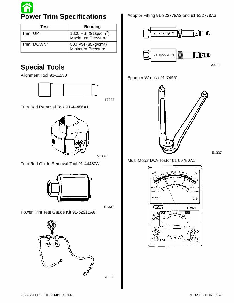
Power Trim SpecificationsTest Reading
Trim “UP” 1300 PSI (91kg/cm2)Maximum Pressure
Trim “DOWN” 500 PSI (35kg/cm2)Minimum Pressure
Special ToolsAlignment Tool 91-11230
17238
Trim Rod Removal Tool 91-44486A1
51337
Trim Rod Guide Removal Tool 91-44487A1
51337Power Trim Test Gauge Kit 91-52915A6
73835
Adaptor Fitting 91-822778A2 and 91-822778A3
54458
Spanner Wrench 91-74951
51337
Multi-Meter DVA Tester 91-99750A1
5B-2 - MID-SECTION 90-822900R3 DECEMBER 1997
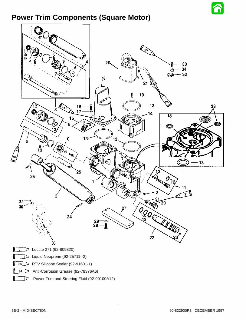
Power Trim Components (Square Motor)
94 Anti-Corrosion Grease (92-78376A6)110 Power Trim and Steering Fluid (92-90100A12)
25 Liquid Neoprene (92-25711--2)
85 RTV Silicone Sealer (92-91601-1)
7 Loctite 271 (92-809820)
90-822900R3 DECEMBER 1997 MID-SECTION - 5B-3
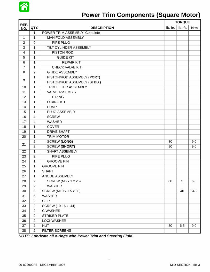
Power Trim Components (Square Motor)REF.
TORQUEREF.NO. QTY. DESCRIPTION lb. in. lb. ft. N·m
-- 1 POWER TRIM ASSEMBLY--Complete1 1 MANIFOLD ASSEMBLY2 9 PIPE PLUG3 1 TILT CYLINDER ASSEMBLY4 1 PISTON ROD5 1 GUIDE KIT6 1 REPAIR KIT7 1 CHECK VALVE KIT8 2 GUIDE ASSEMBLY
91 PISTON/ROD ASSEMBLY (PORT)
9 1 PISTON/ROD ASSEMBLY (STBD.)10 1 TRIM FILTER ASSEMBLY11 1 VALVE ASSEMBLY12 1 E RING13 1 O RING KIT14 1 PUMP15 1 PLUG ASSEMBLY16 4 SCREW17 4 WASHER18 1 COVER19 1 DRIVE SHAFT20 1 TRIM MOTOR
212 SCREW (LONG) 80 9.0
21 2 SCREW (SHORT) 80 9.022 1 SHAFT ASSEMBLY23 2 PIPE PLUG24 1 GROOVE PIN25 1 GROOVE PIN26 1 SHAFT27 1 ANODE ASSEMBLY28 2 SCREW (M6 x 1 x 25) 60 5 6.829 2 WASHER30 6 SCREW (M10 x 1.5 x 30) 40 54.231 6 WASHER32 2 CLIP33 2 SCREW (10-16 x .44)34 2 C WASHER35 2 STRIKER PLATE36 2 LOCKWASHER37 2 NUT 80 6.5 9.038 2 FILTER SCREENS
NOTE: Lubricate all o-rings with Power Trim and Steering Fluid.
5B-4 - MID-SECTION 90-822900R3 DECEMBER 1997
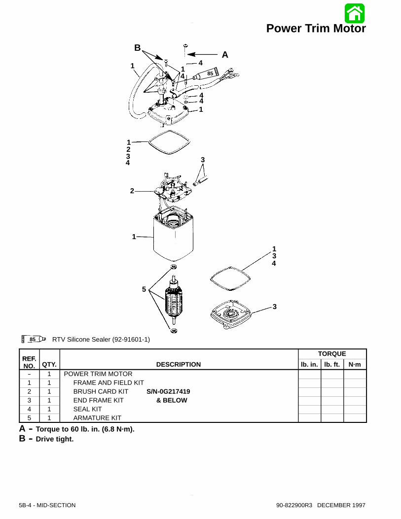
Power Trim Motor
14
85 RTV Silicone Sealer (92-91601-1)
85
AB
1
23
4
5
1
1
1
44
4 3
2
13
3
4
REF.TORQUE
REF.NO. QTY. DESCRIPTION lb. in. lb. ft. N·m
-- 1 POWER TRIM MOTOR1 1 FRAME AND FIELD KIT2 1 BRUSH CARD KIT S/N-0G2174193 1 END FRAME KIT & BELOW4 1 SEAL KIT5 1 ARMATURE KIT
A -- Torque to 60 lb. in. (6.8 N·m).B -- Drive tight.

90-822900R3 DECEMBER 1997 MID-SECTION - 5B-5
Notes:
5B-6 - MID-SECTION 90-822900R3 DECEMBER 1997
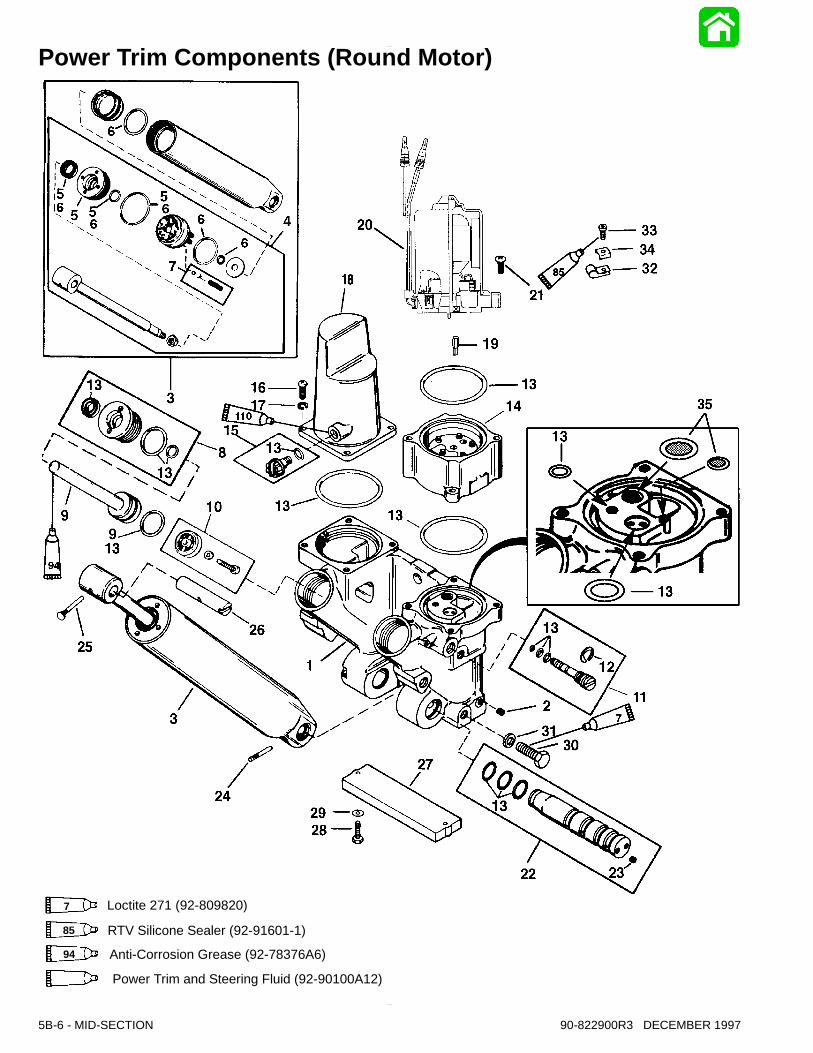
Power Trim Components (Round Motor)
110 Power Trim and Steering Fluid (92-90100A12)
94 Anti-Corrosion Grease (92-78376A6)
85 RTV Silicone Sealer (92-91601-1)
7 Loctite 271 (92-809820)
90-822900R3 DECEMBER 1997 MID-SECTION - 5B-7
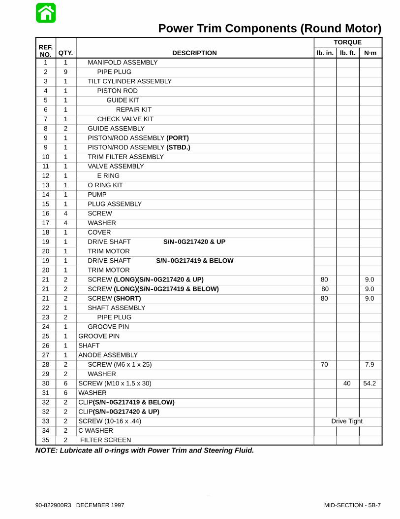
Power Trim Components (Round Motor)REF.
TORQUEREF.NO. QTY. DESCRIPTION lb. in. lb. ft. N·m
1 1 MANIFOLD ASSEMBLY2 9 PIPE PLUG3 1 TILT CYLINDER ASSEMBLY4 1 PISTON ROD5 1 GUIDE KIT6 1 REPAIR KIT7 1 CHECK VALVE KIT8 2 GUIDE ASSEMBLY9 1 PISTON/ROD ASSEMBLY (PORT)9 1 PISTON/ROD ASSEMBLY (STBD.)10 1 TRIM FILTER ASSEMBLY11 1 VALVE ASSEMBLY12 1 E RING13 1 O RING KIT14 1 PUMP15 1 PLUG ASSEMBLY16 4 SCREW17 4 WASHER18 1 COVER19 1 DRIVE SHAFT S/N--0G217420 & UP20 1 TRIM MOTOR19 1 DRIVE SHAFT S/N--0G217419 & BELOW20 1 TRIM MOTOR21 2 SCREW (LONG)(S/N--0G217420 & UP) 80 9.021 2 SCREW (LONG)(S/N--0G217419 & BELOW) 80 9.021 2 SCREW (SHORT) 80 9.022 1 SHAFT ASSEMBLY23 2 PIPE PLUG24 1 GROOVE PIN25 1 GROOVE PIN26 1 SHAFT27 1 ANODE ASSEMBLY28 2 SCREW (M6 x 1 x 25) 70 7.929 2 WASHER30 6 SCREW (M10 x 1.5 x 30) 40 54.231 6 WASHER32 2 CLIP(S/N--0G217419 & BELOW)32 2 CLIP(S/N--0G217420 & UP)33 2 SCREW (10-16 x .44) Drive Tight34 2 C WASHER35 2 FILTER SCREEN
NOTE: Lubricate all o-rings with Power Trim and Steering Fluid.
5B-8 - MID-SECTION 90-822900R3 DECEMBER 1997
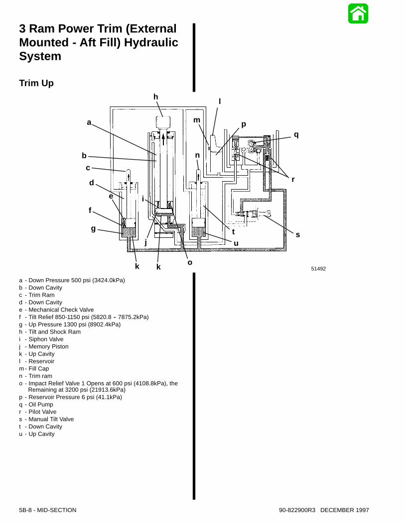
3 Ram Power Trim (ExternalMounted - Aft Fill) HydraulicSystem
Trim Up
51492
a
bc
de
f
g
k k o
j
i
h l
m
n
pq
r
stu
a - Down Pressure 500 psi (3424.0kPa)b - Down Cavityc - Trim Ramd - Down Cavitye - Mechanical Check Valvef - Tilt Relief 850-1150 psi (5820.8 -- 7875.2kPa)g - Up Pressure 1300 psi (8902.4kPa)h - Tilt and Shock Rami - Siphon Valvej - Memory Pistonk - Up Cavityl - Reservoirm - Fill Capn - Trim ramo - Impact Relief Valve 1 Opens at 600 psi (4108.8kPa), the
Remaining at 3200 psi (21913.6kPa)p - Reservoir Pressure 6 psi (41.1kPa)q - Oil Pumpr - Pilot Valves - Manual Tilt Valvet - Down Cavityu - Up Cavity

90-822900R3 DECEMBER 1997 MID-SECTION - 5B-9
3 Ram Power Trim (ExternalMounted - Aft Fill) HydraulicSystem
Hydraulic Tilt
51494
abc
de
f
g
k o
j
i
h
mn
l pq
r
stu
a - Down Pressure 500 psi (3424.0kPa)b - Down Cavityc - Trim Ramd - Down Cavitye - Mechanical Check Valvef - Tilt Relief 850-1150 psi (5820.8 -- 7875.2kPa)g - Up Pressure 1300 psi (8902.4kPa)h - Tilt and Shock Rami - Siphon Valvej - Memory Pistonk - Up Cavityl - Reservoirm - Fill Capn - Trim ramo - Impact Relief Valve 1 Opens at 600 psi (4108.8kPa), the
Remaining at 3200 psi (21913.6kPa)p - Reservoir Pressure 6 psi (41.1kPa)q - Oil Pumpr - Pilot Valves - Manual Tilt Valvet - Down Cavityu - Up Cavity
UP CIRCUITWhen the up button is activated the electric motor willrotate the oil pump gears. As the oil pump gears be-gin to rotate, oil is drawn through the up circuit pickup and into the pump, supplying pressure for the upcircuit. Oil is blocked from returning into the reservoirby the closed check ball inside the down circuit pickup. Oil, under pressure moves the (up) shuttle valveup, oil also flows through the (up) shuttle valve centerpin. Oil flows past the check ball and through a con-necting passage into a chamber above the downshuttle valve. The down shuttle valve and check ballare forced against the spring loaded down circuit pilotcheck valve, opening the pilot check valve and allow-ing oil to return into the pump from the down side cav-ity of the tilt cylinder, which supplies oil to operate the“up circuit”. Oil under pressure opens the up circuit pi-lot check valve, allowing oil to exit through the uppressure port, and into the manifold casting. The oilthen continues on through the up passage into the upcavities below the trim and tilt ram pistons, pushingthe rams up and out. Oil returns into the reservoir,from the trim rams, through passages cast inside ofthe manifold. Oil returning from above the tilt cylinderpiston exits the down cavity through an interconnect-ing passage cast located along side of the cylinder.Oil returns through the lower pivot pin and past theopen pilot valve, into the pump, suppling some of theoil required for the up circuit. Due to the surface areaof their pistons, the small outer trim rams move first.As the trim rams reach the limit of their travel, the me-chanical check valve, on the top of the port trim rampiston, contacts the trim ram cover. The “pin”contactwith the cover mechanically opens the shut off valve,allowing oil, to flow through the piston. The oil flowingthrough the port trim ram lowers the pressure avail-able for the tilt ram (850-1150 psi). However, due tothe smaller diameter of the tilt cylinder, the engine willmove at a faster rate. The tilt cylinder will continue toraise the outboard engine, until reaching its maxi-mum limit. At full travel, the only passage for the oilfrom the pump is through the port trim ram, at a veryslow rate. To supply oil into the pump at this time, asmall amount of oil is drawn up through the oil pickup. If the up button is not released, the electric motorwill heat up and the thermal overload switch, insidethe electric motor will open, stopping the motor. Toprevent the high oil “up”pressure from continuing tomove the engine, after the trim button is released, the“system”pressure must be bleed off. A small bleedpassage past the down circuit oil pick up will allow theup pressure to bleed out of the pump.
5B-10 - MID-SECTION 90-822900R3 DECEMBER 1997
3 Ram Power Trim HydraulicSystemTrim Down
51493
a
b
c
d
e
f
g
k o
j
i
hl
m
n
pq
r
stu
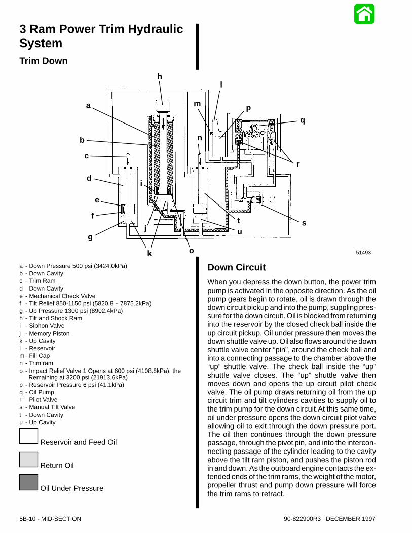
a - Down Pressure 500 psi (3424.0kPa)b - Down Cavityc - Trim Ramd - Down Cavitye - Mechanical Check Valvef - Tilt Relief 850-1150 psi (5820.8 -- 7875.2kPa)g - Up Pressure 1300 psi (8902.4kPa)h - Tilt and Shock Rami - Siphon Valvej - Memory Pistonk - Up Cavityl - Reservoirm - Fill Capn - Trim ramo - Impact Relief Valve 1 Opens at 600 psi (4108.8kPa), the
Remaining at 3200 psi (21913.6kPa)p - Reservoir Pressure 6 psi (41.1kPa)q - Oil Pumpr - Pilot Valves - Manual Tilt Valvet - Down Cavityu - Up Cavity
Reservoir and Feed Oil
Return Oil
Oil Under Pressure
Down CircuitWhen you depress the down button, the power trimpump is activated in the opposite direction. As the oilpump gears begin to rotate, oil is drawn through thedown circuit pickup and into the pump, suppling pres-sure for the down circuit. Oil is blocked from returninginto the reservoir by the closed check ball inside theup circuit pickup. Oil under pressure then moves thedown shuttle valve up. Oil also flows around the downshuttle valve center “pin”, around the check ball andinto a connecting passage to the chamber above the“up” shuttle valve. The check ball inside the “up”shuttle valve closes. The “up” shuttle valve thenmoves down and opens the up circuit pilot checkvalve. The oil pump draws returning oil from the upcircuit trim and tilt cylinders cavities to supply oil tothe trim pump for the down circuit.At this same time,oil under pressure opens the down circuit pilot valveallowing oil to exit through the down pressure port.The oil then continues through the down pressurepassage, through the pivot pin, and into the intercon-necting passage of the cylinder leading to the cavityabove the tilt ram piston, and pushes the piston rodin and down. As the outboard engine contacts the ex-tended ends of the trim rams, the weight of the motor,propeller thrust and pump down pressure will forcethe trim rams to retract.
90-822900R3 DECEMBER 1997 MID-SECTION - 5B-11
3 Ram Power Trim HydraulicSystemBounce and Shock Absorber
51495
a
b
c
de
f
g
k
j
i
hl
m
n
o
ut s
r
qp
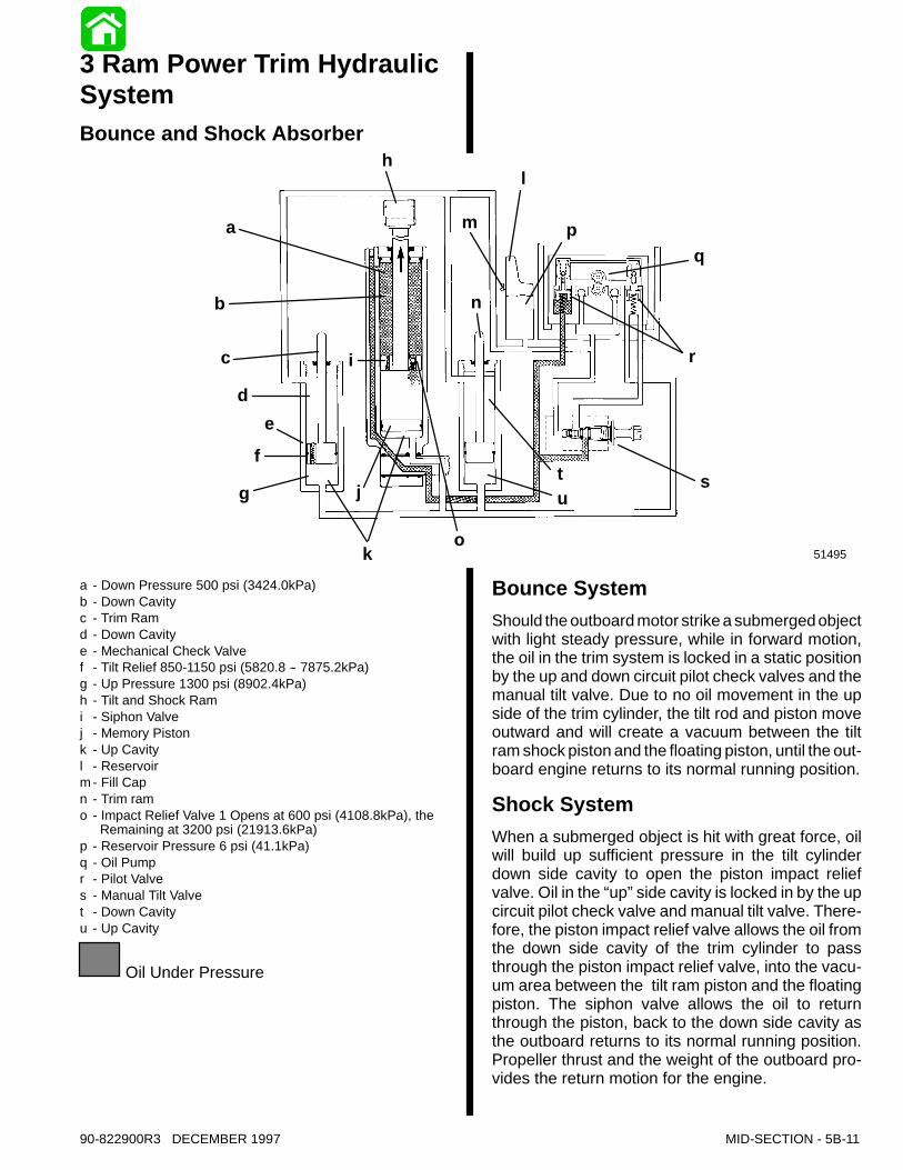
a - Down Pressure 500 psi (3424.0kPa)b - Down Cavityc - Trim Ramd - Down Cavitye - Mechanical Check Valvef - Tilt Relief 850-1150 psi (5820.8 -- 7875.2kPa)g - Up Pressure 1300 psi (8902.4kPa)h - Tilt and Shock Rami - Siphon Valvej - Memory Pistonk - Up Cavityl - Reservoirm - Fill Capn - Trim ramo - Impact Relief Valve 1 Opens at 600 psi (4108.8kPa), the
Remaining at 3200 psi (21913.6kPa)p - Reservoir Pressure 6 psi (41.1kPa)q - Oil Pumpr - Pilot Valves - Manual Tilt Valvet - Down Cavityu - Up Cavity
Oil Under Pressure
Bounce SystemShould the outboard motor strike a submergedobjectwith light steady pressure, while in forward motion,the oil in the trim system is locked in a static positionby the up and down circuit pilot check valves and themanual tilt valve. Due to no oil movement in the upside of the trim cylinder, the tilt rod and piston moveoutward and will create a vacuum between the tiltram shock piston and the floating piston, until the out-board engine returns to its normal running position.
Shock SystemWhen a submerged object is hit with great force, oilwill build up sufficient pressure in the tilt cylinderdown side cavity to open the piston impact reliefvalve. Oil in the “up”side cavity is locked in by the upcircuit pilot check valve and manual tilt valve. There-fore, the piston impact relief valve allows the oil fromthe down side cavity of the trim cylinder to passthrough the piston impact relief valve, into the vacu-um area between the tilt ram piston and the floatingpiston. The siphon valve allows the oil to returnthrough the piston, back to the down side cavity asthe outboard returns to its normal running position.Propeller thrust and the weight of the outboard pro-vides the return motion for the engine.

5B-12 - MID-SECTION 90-822900R3 DECEMBER 1997
3 Ram Power Trim HydraulicSystemManual Tilt
51496
a
b
c
de
fg
h
k o
j
i
ut s
r
qplm
n
a - Down Pressure 500 psi (3424.0kPa)b - Down Cavityc - Trim Ramd - Down Cavitye - Mechanical Check Valvef - Tilt Relief 850-1150 psi (5820.8 -- 7875.2kPa)g - Up Pressure 1300 psi (8902.4kPa)h - Tilt and Shock Rami - Siphon Valvej - Memory Pistonk - Up Cavityl - Reservoirm - Fill Capn - Trim ramo - Impact Relief Valve 1 Opens at 600 psi (4108.8kPa), the
Remaining at 3200 psi (21913.6kPa)p - Reservoir Pressure 6 psi (41.1kPa)q - Oil Pumpr - Pilot Valves - Manual Tilt Valvet - Down Cavityu - Up Cavity
Return Oil
Manual Tilt SystemIf the outboard motor is to be raised manually, turnthe manual release (tilt) valve counterclockwise tothe full out position. When in the full (out) position, oilin the trim cylinder can flow freely from the up side tothe down side or from the down side to the up side.The oil return line into the reservoir is also open, al-lowing free oil flow to either side of the tilt cylinder toaccommodate the differential oil capacities betweenthe tilt cylinder up side and down side cavities.When trimming the outboard in either the up or downposition, with the manual tilt valve open or leaking,little or no movement will occur. Oil pressure from thepump will move to both, the up cavity and through themanual tilt valve into the down cavity, each cavitywould have equal pressure resulting in little or nomovement.
Reverse OperationTo prevent the outboard from coming up or trailingout, when shifted into reverse and/or throttling backrapidly, oil in the trim system must be locked in a staticposition. This is accomplished with the up and downpilot check valves. Thus, not allowing oil in the sys-tem to move in either direction.

90-822900R3 DECEMBER 1997 MID-SECTION - 5B-13
Power Trim - GeneralInformationDescriptionThe Power Trim System consists of an electric motor,pressurized fluid reservoir, pump, tilt cylinder, andtwo trim rams.The remote control (or trim panel) has switches thattrim the outboard “Up”or “Down”and tilt the enginefor “Trailering”. The outboard can be trimmed andtilted under power or when the outboard is not run-ning.
Trimming CharacteristicsNOTE: Because hull designs react differently in vary-ing water conditions, varying the trim position will of-ten improve the ride and boat handling. When trim-ming from a mid-trim position (with outboard trim tabin a straight fore and aft position), expect the follow-ing:
TRIMMING OUTBOARD “UP” (OUT):
WARNINGExcessive trim “Out” may reduce the stability ofsome high speed hulls. To correct instability, re-duce the power gradually and trim the outboard“In” slightly before resuming high speed opera-tion. A rapid reduction in power will result in asudden change of steering torque and maycause additional boat instability.Will lift boat bow, increasing top speed.Transfers steering torque harder to port (left) on in-stallations above 23 in. transom height.Increases gearcase clearance over submerged ob-jects.Excess trim can cause “porpoising”and/or ventila-tion.
WARNINGExcessive outboard trim angle will result in in-sufficient water supply causing water pump and/or powerhead overheating damage. Insure waterlevel is above water intake holes whenever out-board is running.The “Up” circuit actuates the “up” solenoid (underoutboard cowl) and closes the motor circuit. Theelectric motor drives the pump, forcing fluid thru pas-sageways into the “up”side of the trim cylinders.
The trim cylinders position the outboard at the de-sired trim angle in the 20 degree maximum trimrange. The system will not allow the outboard to betrimmed above the 20 degree trim range as long asthe engine RPM is above approximately 2000 RPM.The outboard can be trimmed above the 20 degreemaximum trim angle (for shallow water operation,etc.), by keeping the engine RPM below 2000. If theRPM increases over 2000, propeller thrust (ifpropeller is deep enough) will result in the trimsystem to return the outboard to the 20 degreemaximum trim position.
TRIMMING OUTBOARD “DOWN” (IN):
WARNINGExcessive speed at minimum trim “In”may resultin undesirable and/or unsafe steering condi-tions. Test for handling characteristics after anyadjustment is made to the trim angle (and tilt pinlocation).Aids planing, particularly with heavy loads.Improves ride in choppy water conditions.Excess trim “In”can cause “bow steer”(boat veers toleft or right).Transfers steering torque to starboard (right).Improves acceleration to planing speed.The “Down”circuit actuates the “down”solenoid (un-der engine cowl) and closes the motor circuit. Theelectric motor drives the pump in the opposite direc-tion as the “up”circuit, forcing fluid thru passagewaysinto the “down”side of the tilt ram. The tilt ram movesthe engine down to the desired position.
Trailering OutboardThe “Up”circuit first moves the trim cylinders; whenthe trim cylinders extend fully, the tilt ram extends totilt the outboard to the full “Up”position for trailering.Before the boat is trailered, the operator shouldcheck for clearance between the outboard skeg andpavement to prevent damage to skeg from strikingpavement.If the outboard must be tilted for clearance betweenskeg and pavement, a device such as a “TransomSaver”should be installed to prevent stress to boattransom from outboard weight while the boat/out-board are being trailered.
5B-14 - MID-SECTION 90-822900R3 DECEMBER 1997
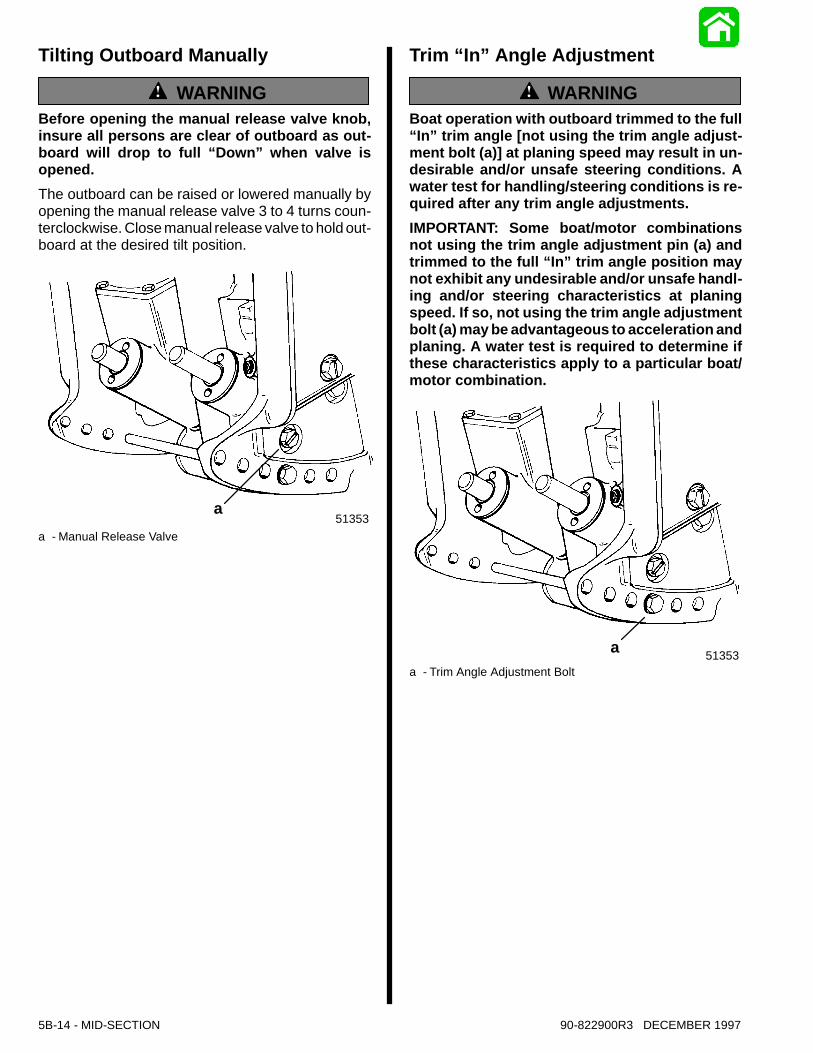
Tilting Outboard Manually
WARNINGBefore opening the manual release valve knob,insure all persons are clear of outboard as out-board will drop to full “Down” when valve isopened.The outboard can be raised or lowered manually byopening the manual release valve 3 to 4 turns coun-terclockwise. Close manual release valve to hold out-board at the desired tilt position.
51353a
a - Manual Release Valve
Trim “In” Angle Adjustment
WARNINGBoat operation with outboard trimmed to the full“In” trim angle [not using the trim angle adjust-ment bolt (a)] at planing speed may result in un-desirable and/or unsafe steering conditions. Awater test for handling/steering conditions is re-quired after any trim angle adjustments.IMPORTANT: Some boat/motor combinationsnot using the trim angle adjustment pin (a) andtrimmed to the full “In” trim angle position maynot exhibit any undesirable and/or unsafe handl-ing and/or steering characteristics at planingspeed. If so, not using the trim angle adjustmentbolt (a) may be advantageous to acceleration andplaning. A water test is required to determine ifthese characteristics apply to a particular boat/motor combination.
51353aa - Trim Angle Adjustment Bolt
90-822900R3 DECEMBER 1997 MID-SECTION - 5B-15
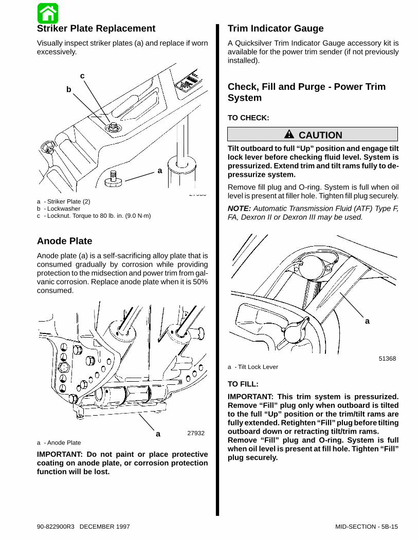
Striker Plate ReplacementVisually inspect striker plates (a) and replace if wornexcessively.
27930
a
bc
a - Striker Plate (2)b - Lockwasherc - Locknut. Torque to 80 lb. in. (9.0 N·m)
Anode PlateAnode plate (a) is a self-sacrificing alloy plate that isconsumed gradually by corrosion while providingprotection to the midsection and power trim from gal-vanic corrosion. Replace anode plate when it is 50%consumed.
27932aa - Anode Plate
IMPORTANT: Do not paint or place protectivecoating on anode plate, or corrosion protectionfunction will be lost.
Trim Indicator GaugeA Quicksilver Trim Indicator Gauge accessory kit isavailable for the power trim sender (if not previouslyinstalled).
Check, Fill and Purge - Power TrimSystem
TO CHECK:
CAUTIONTilt outboard to full “Up”position and engage tiltlock lever before checking fluid level. System ispressurized. Extend trim and tilt rams fully to de-pressurize system.Remove fill plug and O-ring. System is full when oillevel is present at filler hole. Tighten fill plug securely.NOTE: Automatic Transmission Fluid (ATF) Type F,FA, Dexron II or Dexron III may be used.
51368
a
a - Tilt Lock Lever
TO FILL:IMPORTANT: This trim system is pressurized.Remove “Fill” plug only when outboard is tiltedto the full “Up” position or the trim/tilt rams arefully extended. Retighten “Fill”plug before tiltingoutboard down or retracting tilt/trim rams.Remove “Fill” plug and O-ring. System is fullwhen oil level is present at fill hole. Tighten “Fill”plug securely.
5B-16 - MID-SECTION 90-822900R3 DECEMBER 1997
51344
ba
c
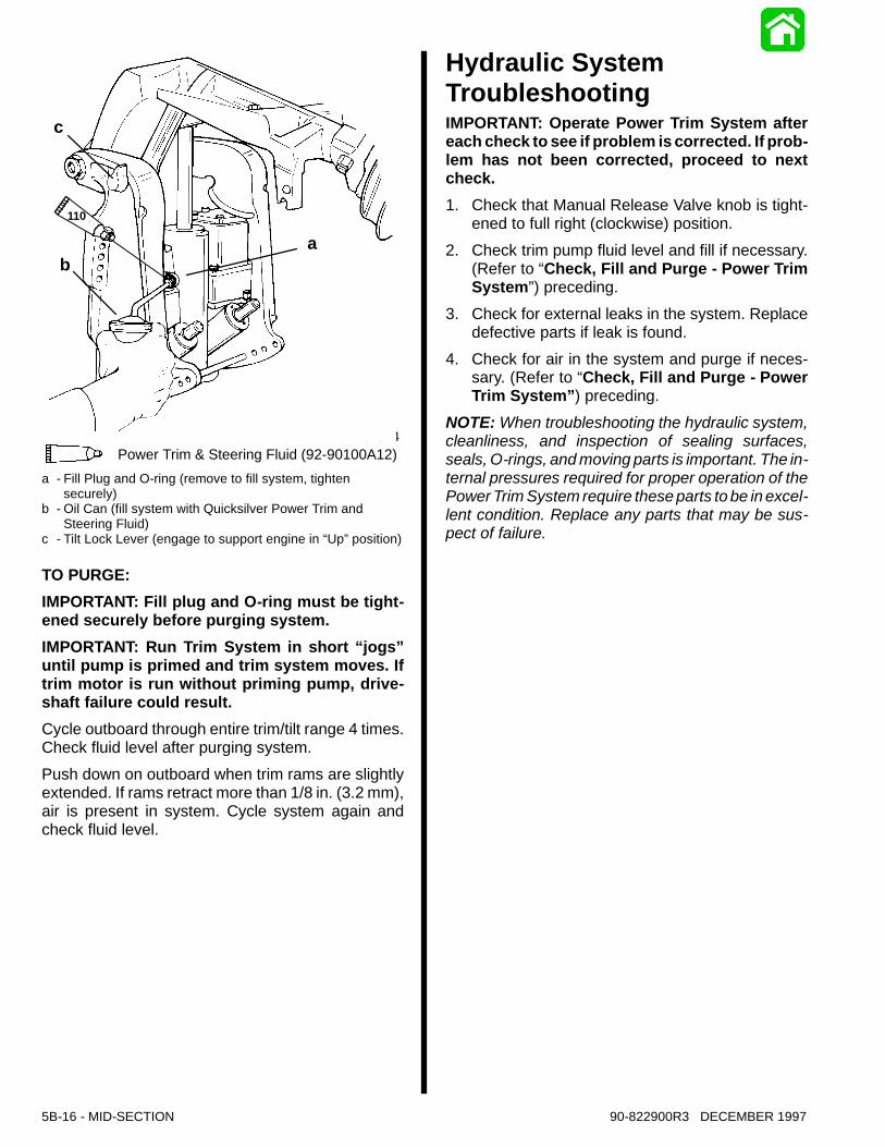
110 Power Trim & Steering Fluid (92-90100A12)
110
a - Fill Plug and O-ring (remove to fill system, tightensecurely)
b - Oil Can (fill system with Quicksilver Power Trim andSteering Fluid)
c - Tilt Lock Lever (engage to support engine in “Up”position)
TO PURGE:IMPORTANT: Fill plug and O-ring must be tight-ened securely before purging system.IMPORTANT: Run Trim System in short “jogs”until pump is primed and trim system moves. Iftrim motor is run without priming pump, drive-shaft failure could result.Cycle outboard through entire trim/tilt range 4 times.Check fluid level after purging system.Push down on outboard when trim rams are slightlyextended. If rams retract more than 1/8 in. (3.2 mm),air is present in system. Cycle system again andcheck fluid level.
Hydraulic SystemTroubleshootingIMPORTANT: Operate Power Trim System aftereach check to see if problem is corrected. If prob-lem has not been corrected, proceed to nextcheck.1. Check that Manual Release Valve knob is tight-
ened to full right (clockwise) position.2. Check trim pump fluid level and fill if necessary.
(Refer to “Check, Fill and Purge - Power TrimSystem”) preceding.
3. Check for external leaks in the system. Replacedefective parts if leak is found.
4. Check for air in the system and purge if neces-sary. (Refer to “Check, Fill and Purge - PowerTrim System”) preceding.
NOTE: When troubleshooting the hydraulic system,cleanliness, and inspection of sealing surfaces,seals, O-rings, and moving parts is important. The in-ternal pressures required for proper operation of thePower Trim System require these parts to be in excel-lent condition. Replace any parts that may be sus-pect of failure.
51491
12
56
7
4
3
10
90-822900R3 DECEMBER 1997 MID-SECTION - 5B-17
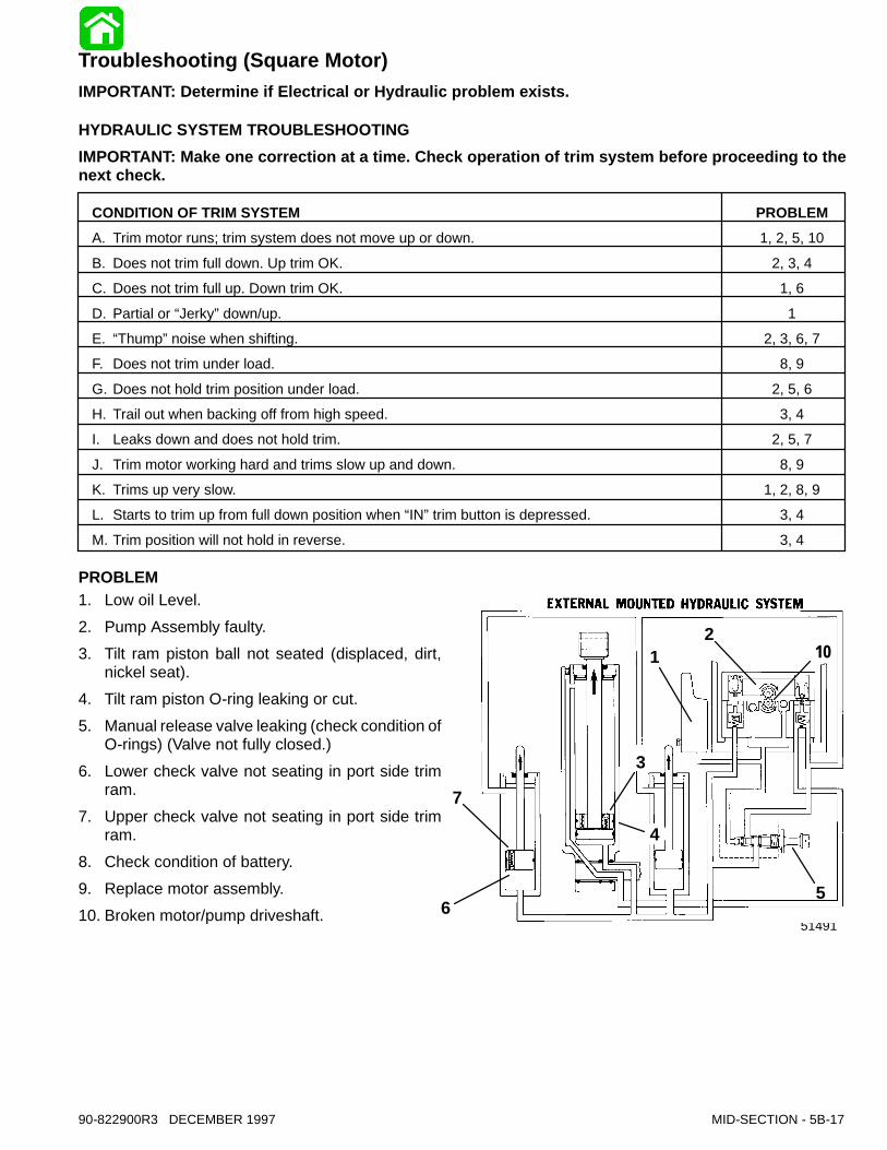
Troubleshooting (Square Motor)IMPORTANT: Determine if Electrical or Hydraulic problem exists.
HYDRAULIC SYSTEM TROUBLESHOOTINGIMPORTANT: Make one correction at a time. Check operation of trim system before proceeding to thenext check.
CONDITION OF TRIM SYSTEM PROBLEMA. Trim motor runs; trim system does not move up or down. 1, 2, 5, 10B. Does not trim full down. Up trim OK. 2, 3, 4C. Does not trim full up. Down trim OK. 1, 6D. Partial or “Jerky”down/up. 1E. “Thump”noise when shifting. 2, 3, 6, 7F. Does not trim under load. 8, 9G. Does not hold trim position under load. 2, 5, 6H. Trail out when backing off from high speed. 3, 4I. Leaks down and does not hold trim. 2, 5, 7J. Trim motor working hard and trims slow up and down. 8, 9K. Trims up very slow. 1, 2, 8, 9L. Starts to trim up from full down position when “IN”trim button is depressed. 3, 4M. Trim position will not hold in reverse. 3, 4
PROBLEM1. Low oil Level.2. Pump Assembly faulty.3. Tilt ram piston ball not seated (displaced, dirt,
nickel seat).4. Tilt ram piston O-ring leaking or cut.5. Manual release valve leaking (check condition of
O-rings) (Valve not fully closed.)6. Lower check valve not seating in port side trim
ram.7. Upper check valve not seating in port side trim
ram.8. Check condition of battery.9. Replace motor assembly.10. Broken motor/pump driveshaft.

51306
COWLTRIMSWITCH
TOTERMINAL
BLOCK
POWERTRIM
MOTOR
FUSE
TO BATTERY
BLK = BlackBLU = BlueBRN = BrownGRY = GrayGRN = GreenORN = OrangePNK = PinkPUR = PurpleRED = RedTAN = Tan
WHT = WhiteYEL = YellowLIT = Light
DRK = Dark
3 6 10
12
1
2
11
9
5B-18 - MID-SECTION 90-822900R3 DECEMBER 1997
ELECTRICAL SYSTEM TROUBLESHOOTING (SQUARE MOTOR)
CONDITION OF TRIM SYSTEM PROBLEMA. Trim motor does not run when trim button is depressed. 1, 2, 4, 5, 6B. Trim system trims opposite of buttons. 3C. Cowl mounted trim buttons do not activate trim system. 2, 4, 5, 6
PROBLEM1. Battery low or discharged.2. Open circuit in trim wiring.3. Wiring reversed in remote control.4. Wire harness corroded through.5. Internal motor problem (brushes, shorted arma-
ture).6. Blown fuse(s).NOTE: Refer to following pages to troubleshoot Pow-er Trim Electrical System.
POWER TRIM SYSTEM WITH SOLENOIDSAND 3 WIRE TRIM MOTOR
23891
54
7
90-822900R3 DECEMBER 1997 MID-SECTION - 5B-19
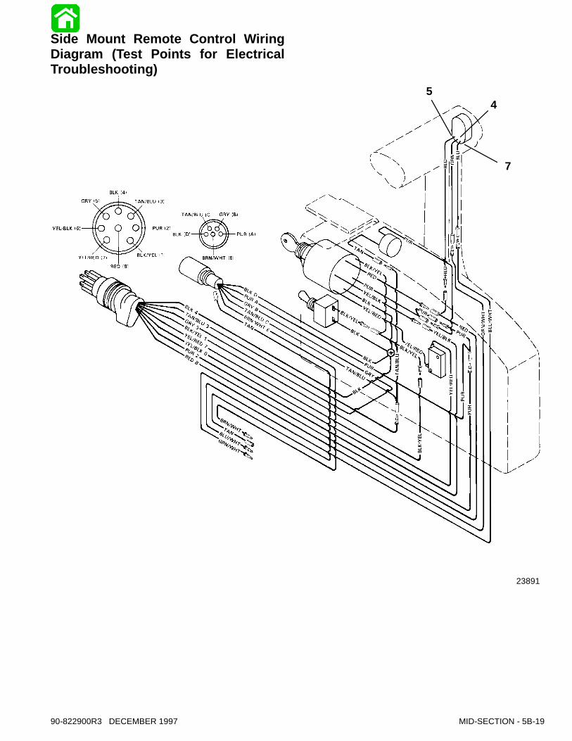
Side Mount Remote Control WiringDiagram (Test Points for ElectricalTroubleshooting)
Battery Voltage Indicated:
Battery Voltage Indicated:
Relay Good:No Voltage Indicated:
No Voltage Indicated:
No Voltage Indicated:
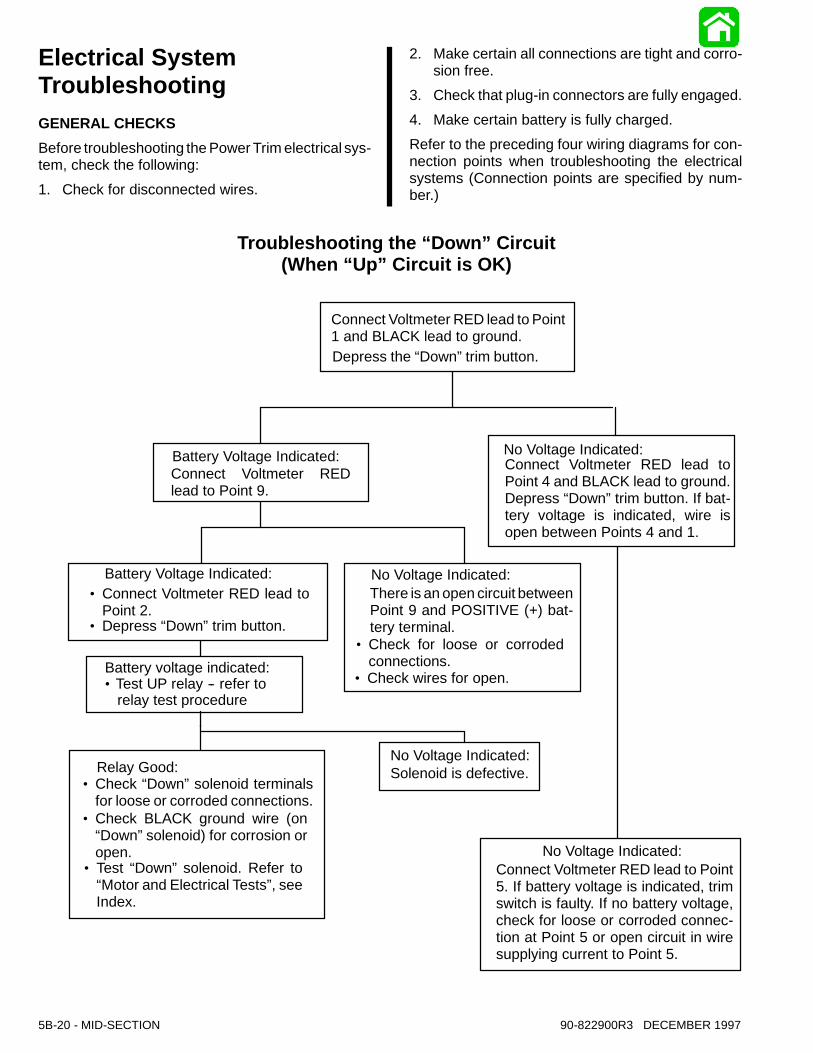
No Voltage Indicated:Connect Voltmeter RED lead to Point5. If battery voltage is indicated, trimswitch is faulty. If no battery voltage,check for loose or corroded connec-tion at Point 5 or open circuit in wiresupplying current to Point 5.
Solenoid is defective.
There is an open circuit betweenPoint 9 and POSITIVE (+) bat-tery terminal.
·Connect Voltmeter RED lead toPoint 2.
Connect Voltmeter REDlead to Point 9.
Connect Voltmeter RED lead toPoint 4 and BLACK lead to ground.Depress “Down”trim button. If bat-tery voltage is indicated, wire isopen between Points 4 and 1.
Connect Voltmeter RED lead to Point1 and BLACK lead to ground.Depress the “Down”trim button.
·Depress “Down”trim button.
·Check “Down”solenoid terminalsfor loose or corroded connections.
·Check BLACK ground wire (on“Down”solenoid) for corrosion oropen.
·Check for loose or corrodedconnections.
·Check wires for open.
Troubleshooting the “Down” Circuit(When “Up” Circuit is OK)
·Test “Down” solenoid. Refer to“Motor and Electrical Tests”, seeIndex.
Battery voltage indicated:·Test UP relay -- refer to
relay test procedure
5B-20 - MID-SECTION 90-822900R3 DECEMBER 1997
Electrical SystemTroubleshootingGENERAL CHECKSBefore troubleshooting the Power Trim electrical sys-tem, check the following:1. Check for disconnected wires.
2. Make certain all connections are tight and corro-sion free.
3. Check that plug-in connectors are fully engaged.4. Make certain battery is fully charged.Refer to the preceding four wiring diagrams for con-nection points when troubleshooting the electricalsystems (Connection points are specified by num-ber.)
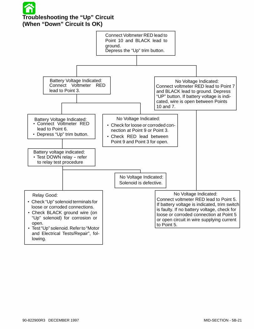
Battery Voltage Indicated:
Battery Voltage Indicated:
Relay Good:
No Voltage Indicated:
No Voltage Indicated:
No Voltage Indicated:
Solenoid is defective.
·Connect Voltmeter REDlead to Point 6.
Connect Voltmeter REDlead to Point 3.
Connect Voltmeter RED lead toPoint 10 and BLACK lead toground.Depress the “Up”trim button.
·Depress “Up”trim button.
·Check “Up”solenoid terminals forloose or corroded connections.
·Check BLACK ground wire (on“Up” solenoid) for corrosion oropen.
·Check for loose or corroded con-nection at Point 9 or Point 3.
·Check RED lead betweenPoint 9 and Point 3 for open.
·Test “Up”solenoid. Refer to“Motorand Electrical Tests/Repair”, fol-lowing.
Connect voltmeter RED lead to Point 7and BLACK lead to ground. Depress“UP”button. If battery voltage is indi-cated, wire is open between Points10 and 7.
No Voltage Indicated:Connect voltmeter RED lead to Point 5.If battery voltage is indicated, trim switchis faulty. If no battery voltage, check forloose or corroded connection at Point 5or open circuit in wire supplying currentto Point 5.
Battery voltage indicated:·Test DOWN relay -- refer
to relay test procedure
90-822900R3 DECEMBER 1997 MID-SECTION - 5B-21
Troubleshooting the “Up” Circuit(When “Down” Circuit Is OK)
Battery Voltage Indicated:
No Voltage Indicated:
Battery Voltage Indicated:
Battery Voltage Indicated:
Battery Voltage Indicated:
No Voltage Indicated:
No Voltage Indicated:
No Voltage Indicated:
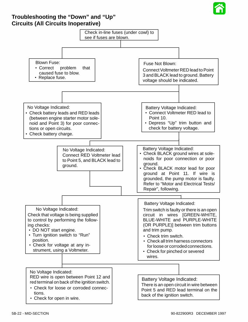
Blown Fuse: Fuse Not Blown:
Check in-line fuses (under cowl) tosee if fuses are blown.
·Correct problem thatcaused fuse to blow.
·Replace fuse.
·Check battery leads and RED leads(between engine starter motor sole-noid and Point 3) for poor connec-tions or open circuits.
·Check battery charge.
·Connect Voltmeter RED lead toPoint 10.
·Depress “Up” trim button andcheck for battery voltage.
·Check BLACK ground wires at sole-noids for poor connection or poorground.
·Check BLACK motor lead for poorground at Point 11. If wire isgrounded, the pump motor is faulty.Refer to “Motor and Electrical Tests/Repair”, following.
·Check for open in wire.
·Check for loose or corroded connec-tions.
·Check for voltage at any in-strument, using a Voltmeter.
·Turn ignition switch to “Run”position.
·DO NOT start engine.
·Check for pinched or severedwires.
·Check all trim harness connectorsfor loose or corrodedconnections.
·Check trim switch.
Connect Voltmeter RED lead to Point3 and BLACK lead to ground. Batteryvoltage should be indicated.
There is an open circuit in wire betweenPoint 5 and RED lead terminal on theback of the ignition switch.
RED wire is open between Point 12 andred terminal on back of the ignition switch.
Check that voltage is being suppliedto control by performing the follow-ing checks:
Connect RED Voltmeter leadto Point 5, and BLACK lead toground.
Trim switch is faulty or there is an opencircuit in wires [GREEN-WHITE,BLUE-WHITE and PURPLE-WHITE(OR PURPLE)] between trim buttonsand trim pump.
5B-22 - MID-SECTION 90-822900R3 DECEMBER 1997
Troubleshooting the “Down” and “Up”Circuits (All Circuits Inoperative)
514916
7
12 10
5
3
4
90-822900R3 DECEMBER 1997 MID-SECTION - 5B-23
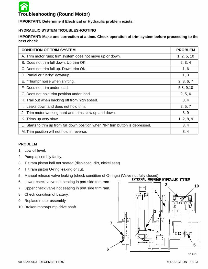
Troubleshooting (Round Motor)IMPORTANT: Determine if Electrical or Hydraulic problem exists.
HYDRAULIC SYSTEM TROUBLESHOOTINGIMPORTANT: Make one correction at a time. Check operation of trim system before proceeding to thenext check.
CONDITION OF TRIM SYSTEM PROBLEMA. Trim motor runs; trim system does not move up or down. 1, 2, 5, 10B. Does not trim full down. Up trim OK. 2, 3, 4C. Does not trim full up. Down trim OK. 1, 6D. Partial or “Jerky”down/up. 1, 3E. “Thump”noise when shifting. 2, 3, 6, 7F. Does not trim under load. 5,8, 9,10G. Does not hold trim position under load. 2, 5, 6H. Trail out when backing off from high speed. 3, 4I. Leaks down and does not hold trim. 2, 5, 7J. Trim motor working hard and trims slow up and down. 8, 9K. Trims up very slow. 1, 2, 8, 9L. Starts to trim up from full down position when “IN”trim button is depressed. 3, 4M. Trim position will not hold in reverse. 3, 4
PROBLEM1. Low oil level.2. Pump assembly faulty.3. Tilt ram piston ball not seated (displaced, dirt, nickel seat).4. Tilt ram piston O-ring leaking or cut.5. Manual release valve leaking (check condition of O-rings) (Valve not fully closed).6. Lower check valve not seating in port side trim ram.7. Upper check valve not seating in port side trim ram.8. Check condition of battery.9. Replace motor assembly.10. Broken motor/pump drive shaft.

5B-24 - MID-SECTION 90-822900R3 DECEMBER 1997
ELECTRICAL SYSTEM TROUBLESHOOTING (ROUND MOTOR)
CONDITION OF TRIM SYSTEM PROBLEMA. Trim motor does not run when trim button is depressed. 1, 2, 4, 5, 6, 7, 8B. Trim system trims opposite of buttons. 3C. Cowl mounted trim buttons do not activate trim system. 2, 4, 5, 6, 7
PROBLEM1. Battery low or discharged.2. Open circuit in trim wiring.3. Wiring reversed in remote control.4. Wire harness corroded through.5. Internal motor problem (brushes, shorted armature).6. Blown fuse(s).7. Trim switch failure.8. Verify relays are functioning correctly.
POWER TRIM RELAY TEST PROCEDUREThe trim motor relay system used on permanentmagnet trim systems connect each of the two wiresfrom the trim motor to either ground or positive in or-der to allow the motor to run in both directions.If the motor will not run in the UP direction, it could beeither the UP relay in not making contact to 12 voltsOR the DOWN relay is not making contact to ground.The opposite is true if the system will not run DOWN.When the system is not energized, both relaysshould connect the heavy motor leads to ground.To test which relay is faulty if the trim system does notoperate in one direction:1. Disconnect the heavy gauge pump wires from
the trim control relay.
2. Check for continuity between the heavy leadsfrom the trim relays to ground.
OhmmeterLeads Between
Resistance(Ohms)
Scale Reading*(x____________)
GREEN andGround
0 Full Continuity(Rx1)
BLUE and Ground 0 Full Continuity(Rx1)
Replace the relay that does not have continuity.3. Connect a voltmeter to the heavy BLUE lead and
to ground. You should have 12 volts on the BLUElead when the UP switch is pushed. You shouldshould also have 12 volts on the GREEN leadwhen the DOWN switch is pushed. Replace therelay that does not switch the lead to positive.
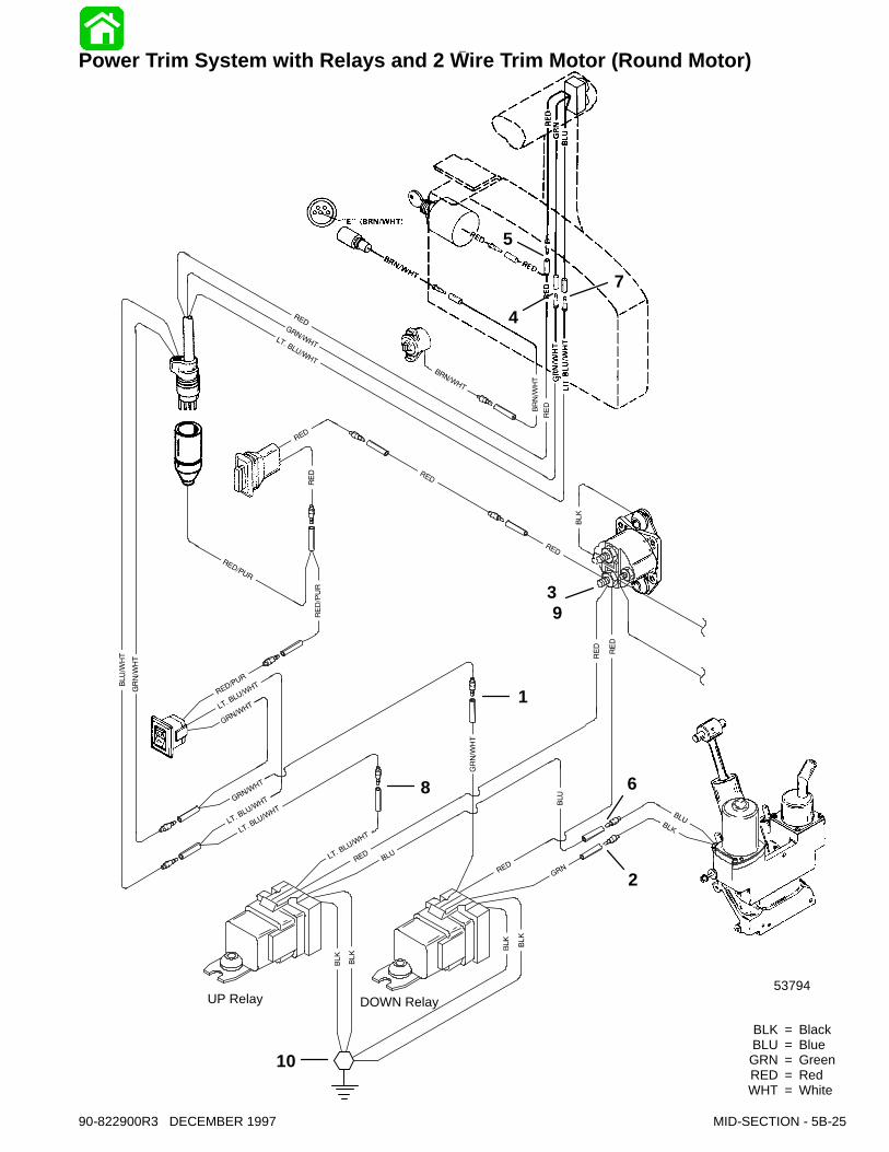
BLK = BlackBLU = BlueGRN = GreenRED = RedWHT = White
DOWN RelayUP Relay53794
7
4
5
39
1
8
2
10
6
90-822900R3 DECEMBER 1997 MID-SECTION - 5B-25
Power Trim System with Relays and 2 Wire Trim Motor (Round Motor)

Battery Voltage Indicated:
Battery Voltage Indicated:
Battery Voltage Indicated: No Voltage Indicated:
No Voltage Indicated:
No Voltage Indicated:
No Voltage Indicated:Connect Voltmeter red leadto Point 5. If battery voltageis indicated, trim switch isfaulty. If no battery voltage,check for loose or corrodedconnection at Point 5 oropen circuit in wire supply-ing current to Point 5.
Relay Switch is defective.
There is an open circuit be-tween Point 3 and positive(+) battery terminal.
·Connect Voltmeter red leadto Point 2.
Connect Voltmeter red lead toPoint 3.
Connect Voltmeter red lead toPoint 4 and black lead toground. Depress “Down”trimbutton. If battery voltage is in-dicated, wire is open betweenPoints 4 and 1.
Connect Voltmeter red lead toPoint 1 and black lead toground.Depress the “Down”trim but-ton.
·Depress “Down” trim but-ton.
·Pump motor wiring is de-fective.·Pump motor is defective.
·Check for loose or cor-roded connections.·Check wires for open.
5B-26 - MID-SECTION 90-822900R3 DECEMBER 1997
Electrical SystemTroubleshooting (RoundMotor)GENERAL CHECKSBefore troubleshooting the Power Trim electrical sys-tem, check the following:1. Check for disconnected wires.
2. Make certain all connections are tight and corro-sion free.
3. Check that plug-in connectors are fully engaged.4. Make certain battery is fully charged.Refer to the preceding four wiring diagrams for con-nection points when troubleshooting the electricalsystems (Connection points are specified by num-ber.)
Troubleshooting the “Down Circuit”
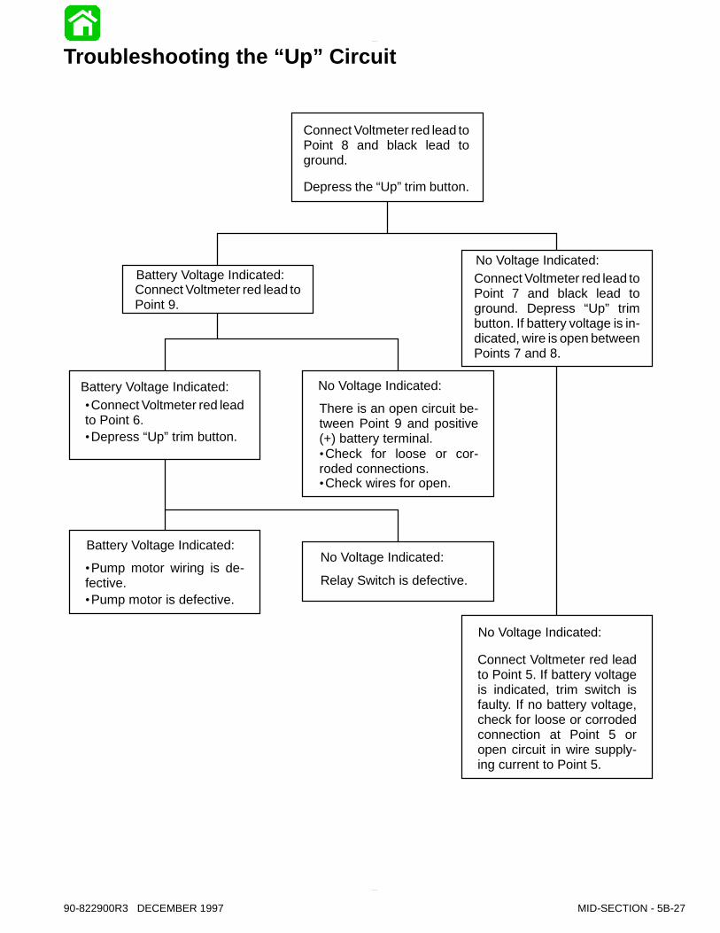
Troubleshooting the “Up” Circuit
Battery Voltage Indicated:
Battery Voltage Indicated:
Battery Voltage Indicated:No Voltage Indicated:
No Voltage Indicated:
No Voltage Indicated:
No Voltage Indicated:
Connect Voltmeter red leadto Point 5. If battery voltageis indicated, trim switch isfaulty. If no battery voltage,check for loose or corrodedconnection at Point 5 oropen circuit in wire supply-ing current to Point 5.
Relay Switch is defective.
There is an open circuit be-tween Point 9 and positive(+) battery terminal.
·Connect Voltmeter red leadto Point 6.
Connect Voltmeter red lead toPoint 9.
Connect Voltmeter red lead toPoint 7 and black lead toground. Depress “Up” trimbutton. If battery voltage is in-dicated, wire is open betweenPoints 7 and 8.
Connect Voltmeter red lead toPoint 8 and black lead toground.
Depress the “Up”trim button.
·Depress “Up”trim button.
·Pump motor wiring is de-fective.·Pump motor is defective.
·Check for loose or cor-roded connections.·Check wires for open.
90-822900R3 DECEMBER 1997 MID-SECTION - 5B-27

Troubleshooting the “Down” and “Up” Circuits(All Circuits Inoperative)
Battery Voltage Indicated:
No Voltage Indicated:
Battery Voltage Indicated:
Battery Voltage Indicated:
Battery Voltage Indicated:
No Voltage Indicated:
No Voltage Indicated:
No Voltage Indicated:
Blown Fuse: Fuse Not Blown:
Check in-line fuse (undercowl) to see if fuse is blown.
·Correct problem thatcaused fuse to blow.·Replace fuse.
·Check battery leads forpoor connections or opencircuits.
·Check battery charge.
·Connect Voltmeter red leadto Point 8 and black lead toground.·Depress “Up”trim button andcheck for battery voltage.
·Check black ground wiresfor poor connection or poorground, Point 10.·Pump motor is faulty. Referto “Motor and ElectricalTests/Repair”, following.
·Check for open in wire.
·Check for loose or cor-roded connections.
·Check for voltage at any instru-ment, using a Voltmeter.
·Turn ignition switch to“Run”position.
·DO NOT start engine.
·Check for pinched or se-vered wires.
·Check all trim harness con-nectors for loose or cor-roded connections.
·Check trim switch.
Connect Voltmeter red leadto Point 3 and black lead toground. Battery voltageshould be indicated.
There is an open circuit inwire between Point 5 andRed terminal on the back ofthe ignition switch.
Red wire is open betweenPoint 3 and red terminal onback of the ignition switch.
Check that voltage is beingsupplied to control by perform-ing the following checks:
Connect red Voltmeter leadto Point 5, and black lead toground.
Trim switch is faulty or there isan open circuit in wires (green-white, blue-white) between trimbuttons and trim pump.
5B-28 - MID-SECTION 90-822900R3 DECEMBER 1997
90-822900R3 DECEMBER 1997 MID-SECTION - 5B-29
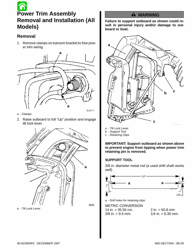
Power Trim AssemblyRemoval and Installation (AllModels)Removal1. Remove clamps on transom bracket to free pow-
er trim wiring.
51377
a
a
a - Clamps
2. Raise outboard to full “Up”position and engagetilt lock lever.
50605
a
a - Tilt Lock Lever
WARNINGFailure to support outboard as shown could re-sult in personal injury and/or damage to out-board or boat.
51346
a
b c
ca - Tilt Lock Leverb - Support Toolc - Retaining Clips
IMPORTANT: Support outboard as shown aboveto prevent engine from tipping when power trimretaining pin is removed.
SUPPORT TOOL3/8 in. diameter metal rod (a used shift shaft workswell)
14”
2”
1/4”
a a
a - Drill holes for retaining clips
METRIC CONVERSION14 in. = 35.56 cm. 2 in. = 50.8 mm3/8 in. = 9.5 mm. 1/4 in. = 6.35 mm.

5B-30 - MID-SECTION 90-822900R3 DECEMBER 1997
CAUTIONDisconnect battery cables at battery before re-moving power trim wires from solenoids.3. Disconnect power trim wires at solenoids (BLUE,
GREEN, and BLACK) or if relay style, disconnect(BLUE and GREEN) bullet connector harness.
4. Open filler cap and release any remaining pres-sure in the system.
51339
a
a - Filler Cap
IMPORTANT: Outboards equipped with thru-the-tilt-tube steering - remove steering link arm fromend of steering cable and cable retaining nutfrom tilt tube.
51354a
a - Retaining Nut
5. Remove outboard transom mounting bolts, andloosen tilt tube nut until nut is flush with end of tilttube thread.
51375
b
a
a
a - Transom Mount Bolts (2)b - Tilt Tube Nut (flush with end of thread)
6. Remove 3 screws and washers and move star-board transom bracket.
51375
ab
a - Screws (3)b - Washers (3)
90-822900R3 DECEMBER 1997 MID-SECTION - 5B-31
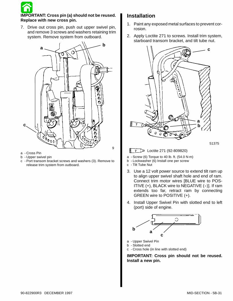
IMPORTANT: Cross pin (a) should not be reused.Replace with new cross pin.7. Drive out cross pin, push out upper swivel pin,
and remove 3 screws and washers retaining trimsystem. Remove system from outboard.
51339
a b
c
a - Cross Pinb - Upper swivel pinc - Port transom bracket screws and washers (3). Remove to
release trim system from outboard.
Installation1. Paint any exposed metal surfaces to prevent cor-
rosion.2. Apply Loctite 271 to screws. Install trim system,
starboard transom bracket, and tilt tube nut.
51375
ab
c
7 Loctite 271 (92-809820)
7
a - Screw (6) Torque to 40 lb. ft. (54.0 N·m)b - Lockwasher (6) Install one per screwc - Tilt Tube Nut
3. Use a 12 volt power source to extend tilt ram upto align upper swivel shaft hole and end of ram.Connect trim motor wires [BLUE wire to POS-ITIVE (+), BLACK wire to NEGATIVE (--)]. If ramextends too far, retract ram by connectingGREEN wire to POSITIVE (+).
4. Install Upper Swivel Pin with slotted end to left(port) side of engine.
b ac
a - Upper Swivel Pinb - Slotted endc - Cross hole (in line with slotted end)
IMPORTANT: Cross pin should not be reused.Install a new pin.
5B-32 - MID-SECTION 90-822900R3 DECEMBER 1997
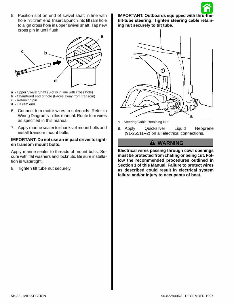
5. Position slot on end of swivel shaft in line withhole in tilt ram end. Insert a punch into tilt ram holeto align cross hole in upper swivel shaft. Tap newcross pin in until flush.
c b
d
a
a - Upper Swivel Shaft (Slot is in line with cross hole)b - Chamfered end of hole (Faces away from transom)c - Retaining pind - Tilt ram end
6. Connect trim motor wires to solenoids. Refer toWiring Diagrams in this manual. Route trim wiresas specified in this manual.
7. Apply marine sealer to shanks of mount bolts andinstall transom mount bolts.
IMPORTANT: Do not use an impact driver to tight-en transom mount bolts.Apply marine sealer to threads of mount bolts. Se-cure with flat washers and locknuts. Be sure installa-tion is watertight.8. Tighten tilt tube nut securely.
IMPORTANT: Outboards equipped with thru-the-tilt-tube steering: Tighten steering cable retain-ing nut securely to tilt tube.
51354aa - Steering Cable Retaining Nut
9. Apply Quicksilver Liquid Neoprene(91-25511--2) on all electrical connections.
WARNINGElectrical wires passing through cowl openingsmust be protected from chafing or being cut. Fol-low the recommended procedures outlined inSection 1 of this Manual. Failure to protect wiresas described could result in electrical systemfailure and/or injury to occupants of boat.
90-822900R3 DECEMBER 1997 MID-SECTION - 5B-33
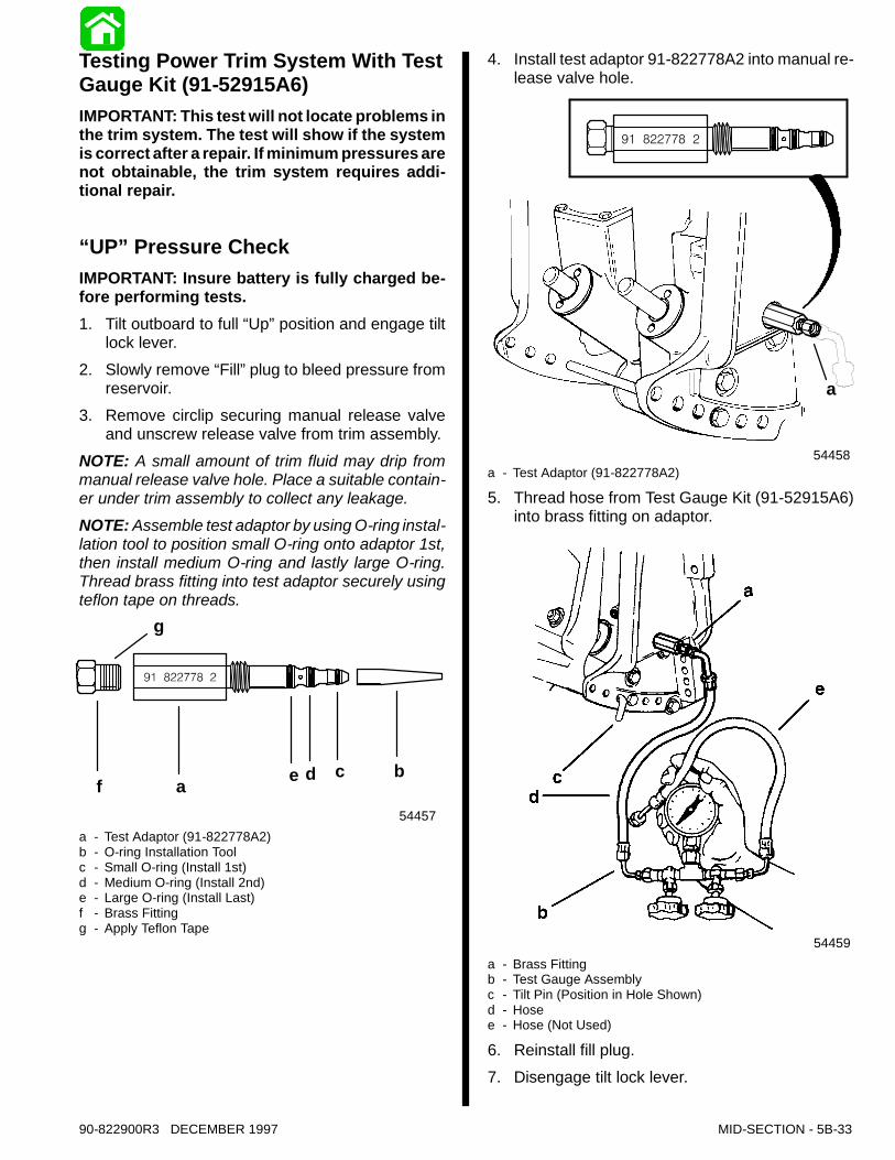
Testing Power Trim System With TestGauge Kit (91-52915A6)IMPORTANT: This test will not locate problems inthe trim system. The test will show if the systemis correct after a repair. If minimum pressures arenot obtainable, the trim system requires addi-tional repair.
“UP” Pressure CheckIMPORTANT: Insure battery is fully charged be-fore performing tests.1. Tilt outboard to full “Up”position and engage tilt
lock lever.2. Slowly remove “Fill”plug to bleed pressure from
reservoir.3. Remove circlip securing manual release valve
and unscrew release valve from trim assembly.NOTE: A small amount of trim fluid may drip frommanual release valve hole. Place a suitable contain-er under trim assembly to collect any leakage.NOTE: Assemble test adaptor by using O-ring instal-lation tool to position small O-ring onto adaptor 1st,then install medium O-ring and lastly large O-ring.Thread brass fitting into test adaptor securely usingteflon tape on threads.
e d c ba
54457
g
f
a - Test Adaptor (91-822778A2)b - O-ring Installation Toolc - Small O-ring (Install 1st)d - Medium O-ring (Install 2nd)e - Large O-ring (Install Last)f - Brass Fittingg - Apply Teflon Tape
4. Install test adaptor 91-822778A2 into manual re-lease valve hole.
54458
a
a - Test Adaptor (91-822778A2)
5. Thread hose from Test Gauge Kit (91-52915A6)into brass fitting on adaptor.
54459a - Brass Fittingb - Test Gauge Assemblyc - Tilt Pin (Position in Hole Shown)d - Hosee - Hose (Not Used)
6. Reinstall fill plug.7. Disengage tilt lock lever.

5B-34 - MID-SECTION 90-822900R3 DECEMBER 1997
CAUTIONFailure to install spare tilt pin (or hardened boltsand nuts) in hole shown could result in transombracket failure and possible injury.8. Move outboard “IN”until hole in swivel bracket
“ear”aligns with the 3rd tilt hole in transom brack-et. Lock engine in trim range by installing a 3/8 in.(9.5 mm) diameter tilt pin or two 3/8 in. (9.5 mm)hardened bolts and nuts thru the transom brack-ets and swivel bracket in the hole shown.
a 54460a - Tilt Pin Hole (Install Spare Tilt Pin or Hardened Bolts and
Nuts)
9. Open valve (a) and close valve (b).
51374
a b
10. Run trim “UP”. The minimum pressure should be1300 psi (8902.4kPa).
11. Run trim “DOWN” to release pressure and re-move spare tilt pin or bolts and nuts.
12. Tilt outboard full “UP”and engage tilt lock lever.13. Slowly remove “Fill”plug to bleed pressure.14. Remove test gauge hose and adapter.15. Reinstall Manual Release Valve and secure
valve with circlip.
16. Retighten “Fill”plug.NOTE: If pressure is less than 1300 psi (8902.4kPa),troubleshoot system per instructions on page 5B-16.
“DOWN” Pressure CheckIMPORTANT: Insure battery is fully charged be-fore performing tests.1. Tilt outboard to full “Up”position and engage tilt
lock lever.2. Slowly remove “Fill”plug to bleed pressure from
reservoir.3. Remove circlip securing manual release valve
and unscrew release valve from trim assembly.NOTE: A small amount of trim fluid may drip frommanual release valve hole. Place a suitable contain-er under trim assembly to collect any leakage.NOTE: Assemble test adaptor by using O-ring instal-lation tool to position small O-ring onto adaptor 1st,then install medium O-ring and lastly large O-ring.Thread brass fitting into test adaptor securely usingteflon tape on threads.
54457
f e d ca
b
3
g
a - Test Adaptor (91-822778A3)b - O-ring Installation Toolc - Small O-ring (Install 1st)d - Medium O-ring (Install 2nd)e - Large O-ring (Install Last)f - Brass Fittingg - Apply Teflon Tape
90-822900R3 DECEMBER 1997 MID-SECTION - 5B-35
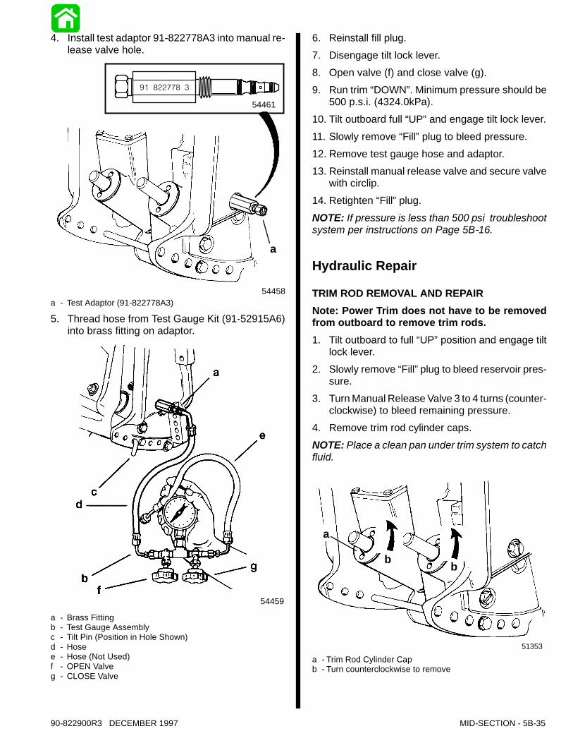
4. Install test adaptor 91-822778A3 into manual re-lease valve hole.
54458
a
54461
a - Test Adaptor (91-822778A3)
5. Thread hose from Test Gauge Kit (91-52915A6)into brass fitting on adaptor.
54459
a - Brass Fittingb - Test Gauge Assemblyc - Tilt Pin (Position in Hole Shown)d - Hosee - Hose (Not Used)f - OPEN Valveg - CLOSE Valve
6. Reinstall fill plug.7. Disengage tilt lock lever.8. Open valve (f) and close valve (g).9. Run trim “DOWN”. Minimum pressure should be
500 p.s.i. (4324.0kPa).10. Tilt outboard full “UP”and engage tilt lock lever.11. Slowly remove “Fill”plug to bleed pressure.12. Remove test gauge hose and adaptor.13. Reinstall manual release valve and secure valve
with circlip.14. Retighten “Fill”plug.NOTE: If pressure is less than 500 psi troubleshootsystem per instructions on Page 5B-16.
Hydraulic Repair
TRIM ROD REMOVAL AND REPAIRNote: Power Trim does not have to be removedfrom outboard to remove trim rods.1. Tilt outboard to full “UP”position and engage tilt
lock lever.2. Slowly remove “Fill”plug to bleed reservoir pres-
sure.3. Turn Manual Release Valve 3 to 4 turns (counter-
clockwise) to bleed remaining pressure.4. Remove trim rod cylinder caps.NOTE: Place a clean pan under trim system to catchfluid.
51353
b
a
b
a - Trim Rod Cylinder Capb - Turn counterclockwise to remove

5B-36 - MID-SECTION 90-822900R3 DECEMBER 1997
51337
b
a
a - Removal Tool (91-44487A1)b - Spanner Wrench (91-74951)
5. Install trim rod removal tool and pull trim rod fromcylinder.
27933
a
a - Trim Rod Removal Tool (91-44486A1)
CLEANING AND INSPECTION - TRIM RODSAND CAPS
CAUTIONDo not remove check valve (a). Check valve ispreset to operate at a specific pressure. Removaland installation of check valve could result in im-proper operating pressure and possible systemdamage.NOTE: Check valve is in port side trim rod only.1. Inspect check valve and check valve screen for
debris; if debris cannot be removed, replace trimrod assembly. Clean trim rod with parts cleanerand dry with compressed air.
51352
a
ba - Check valveb - Check valve screen
Trim Rod End Cap Seal1. Inspect trim cap end seal and replace if damaged
or if seal does not keep trim rod clean.
51343
a
a - Seal (Remove as shown)
2. Install new seal with seal lip up.
90-822900R3 DECEMBER 1997 MID-SECTION - 5B-37
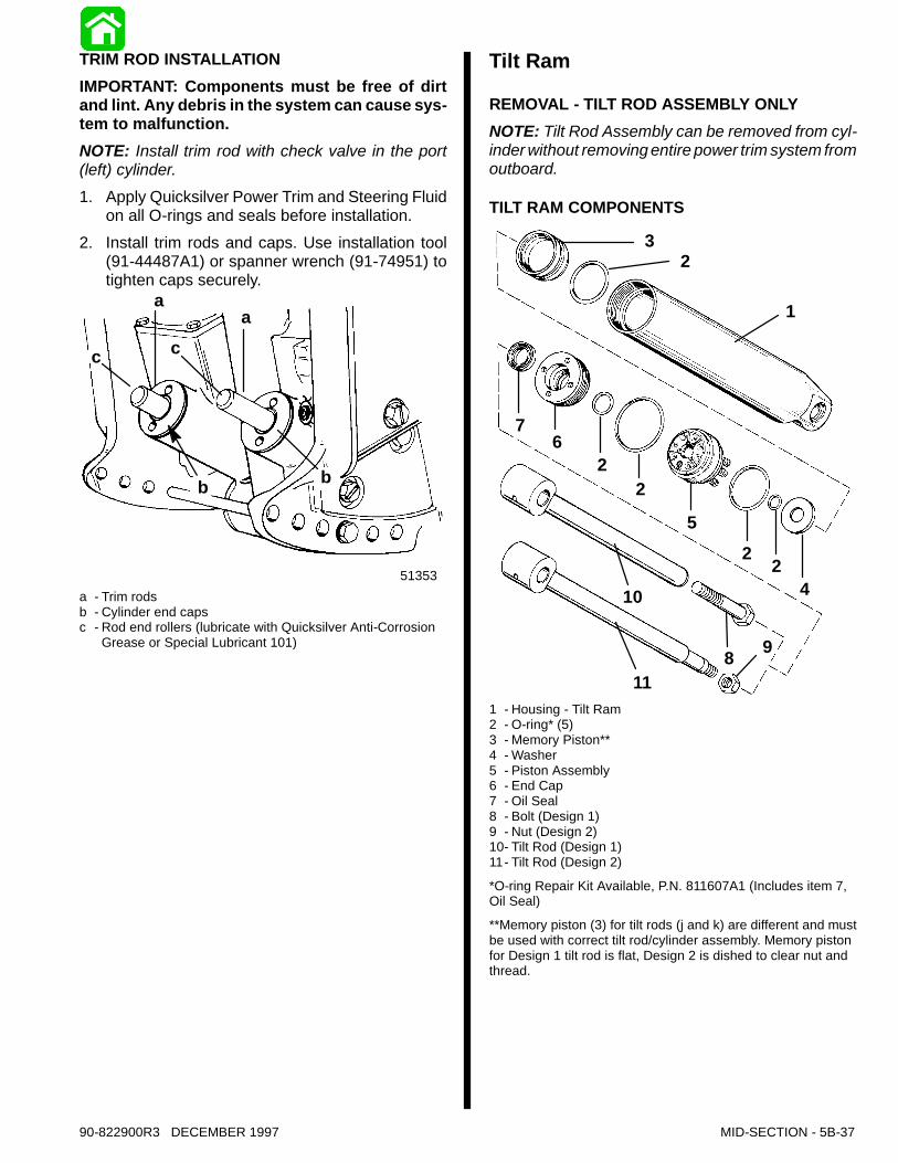
TRIM ROD INSTALLATIONIMPORTANT: Components must be free of dirtand lint. Any debris in the system can cause sys-tem to malfunction.NOTE: Install trim rod with check valve in the port(left) cylinder.1. Apply Quicksilver Power Trim and Steering Fluid
on all O-rings and seals before installation.2. Install trim rods and caps. Use installation tool
(91-44487A1) or spanner wrench (91-74951) totighten caps securely.
51353
a
ca
c
b b
a - Trim rodsb - Cylinder end capsc - Rod end rollers (lubricate with Quicksilver Anti-Corrosion
Grease or Special Lubricant 101)
Tilt Ram
REMOVAL - TILT ROD ASSEMBLY ONLYNOTE: Tilt Rod Assembly can be removed from cyl-inder without removing entire power trim system fromoutboard.
TILT RAM COMPONENTS
51372
1
3
42
25
22
67
10
118 9
2
1 - Housing - Tilt Ram2 - O-ring* (5)3 - Memory Piston**4 - Washer5 - Piston Assembly6 - End Cap7 - Oil Seal8 - Bolt (Design 1)9 - Nut (Design 2)10- Tilt Rod (Design 1)11- Tilt Rod (Design 2)
*O-ring Repair Kit Available, P.N. 811607A1 (Includes item 7,Oil Seal)
**Memory piston (3) for tilt rods (j and k) are different and mustbe used with correct tilt rod/cylinder assembly. Memory pistonfor Design 1 tilt rod is flat, Design 2 is dished to clear nut andthread.

5B-38 - MID-SECTION 90-822900R3 DECEMBER 1997
TILT RAM REMOVAL - POWER TRIM SYSTEMREMOVED FROM OUTBOARD
CAUTIONInsure trim system is depressurized prior to tiltram removal.1. Remove cross pin.
51366aa - Cross Pin (Remove as shown)
2. Remove lower swivel pin.
51355
a
a - Lower Swivel Pin (Remove as shown)
Disassembly1. Secure tilt ram in a soft jawed vise. Remove tilt
rod and cap.
51364
51337
91-74951
a
c
b
a - Cap (Turn counterclockwise to remove)b - Spanner wrench (91-74951)c - Tilt Rod - Pull to remove
2. Clamp tilt rod in a soft jawed vise. Remove bolt ornut as applicable to disassemble rod assembly.Remove O-ring.
51378
51340
ab
a - Bolt (Design 1) or Stud/Nut (Design 2)b - O-Ring
90-822900R3 DECEMBER 1997 MID-SECTION - 5B-39
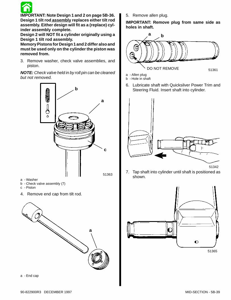
IMPORTANT: Note Design 1 and 2 on page 5B-36.Design 1 tilt rod assembly replaces either tilt rodassembly. Either design will fit as a (replace) cyl-inder assembly complete.Design 2 will NOT fit a cylinder originally using aDesign 1 tilt rod assembly.Memory Pistons for Design 1 and 2 differ also andmust be used only on the cylinder the piston wasremoved from.3. Remove washer, check valve assemblies, and
piston.NOTE: Check valve held in by roll pin can be cleanedbut not removed.
51363
b
a
c
a - Washerb - Check valve assembly (7)c - Piston
4. Remove end cap from tilt rod.
51376
a
a - End cap
5. Remove allen plug.IMPORTANT: Remove plug from same side asholes in shaft.
51361DO NOT REMOVE
a b
a - Allen plugb - Hole in shaft
6. Lubricate shaft with Quicksilver Power Trim andSteering Fluid. Insert shaft into cylinder.
513427. Tap shaft into cylinder until shaft is positioned as
shown.
51365
5B-40 - MID-SECTION 90-822900R3 DECEMBER 1997
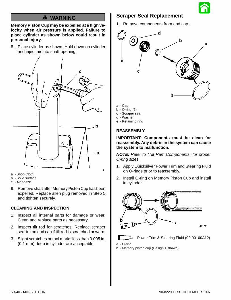
WARNINGMemory Piston Cup may be expelled at a high ve-locity when air pressure is applied. Failure toplace cylinder as shown below could result inpersonal injury.8. Place cylinder as shown. Hold down on cylinder
and inject air into shaft opening.
51353
c
b
a
a - Shop Clothb - Solid surfacec - Air nozzle
9. Remove shaft after Memory Piston Cup has beenexpelled. Replace allen plug removed in Step 5and tighten securely.
CLEANING AND INSPECTION1. Inspect all internal parts for damage or wear.
Clean and replace parts as necessary.2. Inspect tilt rod for scratches. Replace scraper
seal in rod end cap if tilt rod is scratched or worn.3. Slight scratches or tool marks less than 0.005 in.
(0.1 mm) deep in cylinder are acceptable.
Scraper Seal Replacement1. Remove components from end cap.
e
c
b
db
a
a - Capb - O-ring (2)c - Scraper seald - Washere - Retaining ring
REASSEMBLYIMPORTANT: Components must be clean forreassembly. Any debris in the system can causethe system to malfunction.NOTE: Refer to “Tilt Ram Components”for properO-ring sizes.1. Apply Quicksilver Power Trim and Steering Fluid
on O-rings prior to reassembly.2. Install O-ring on Memory Piston Cup and install
in cylinder.
110 Power Trim & Steering Fluid (92-90100A12)a - O-ringb - Memory piston cup (Design 1 shown)
90-822900R3 DECEMBER 1997 MID-SECTION - 5B-41
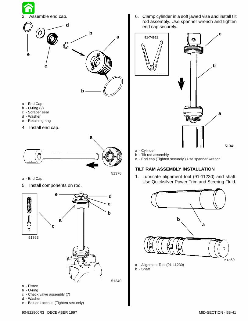
3. Assemble end cap.
d
e
c
ba
b
a - End Capb - O-ring (2)c - Scraper seald - Washere - Retaining ring
4. Install end cap.
51376
a
a - End Cap
5. Install components on rod.
51340
51363
e
ac
dc
b
a - Pistonb - O-ringc - Check valve assembly (7)d - Washere - Bolt or Locknut. (Tighten securely)
6. Clamp cylinder in a soft jawed vise and install tiltrod assembly. Use spanner wrench and tightenend cap securely.
51341
51337
91-74951c
b
a
a - Cylinderb - Tilt rod assemblyc - End cap (Tighten securely.) Use spanner wrench.
TILT RAM ASSEMBLY INSTALLATION1. Lubricate alignment tool (91-11230) and shaft.
Use Quicksilver Power Trim and Steering Fluid.
51369
ab
a - Alignment Tool (91-11230)b - Shaft
5B-42 - MID-SECTION 90-822900R3 DECEMBER 1997
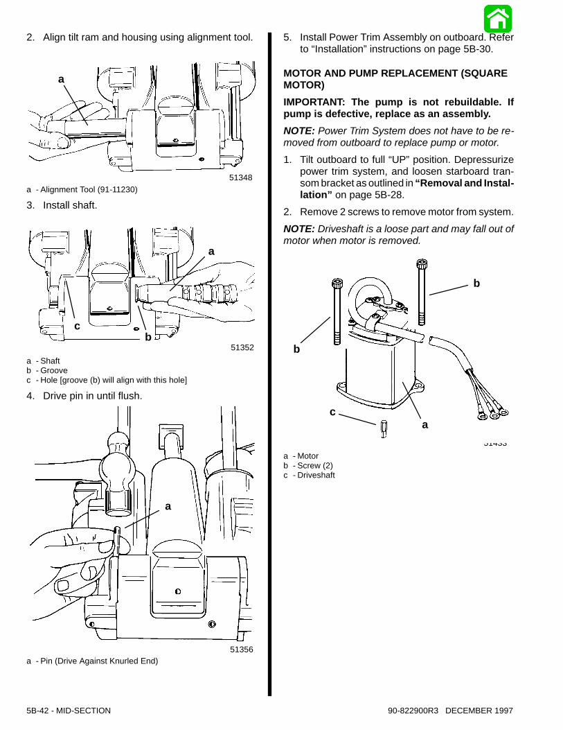
2. Align tilt ram and housing using alignment tool.
51348
a
a - Alignment Tool (91-11230)
3. Install shaft.
51352
a
cb
a - Shaftb - Groovec - Hole [groove (b) will align with this hole]
4. Drive pin in until flush.
51356
a
a - Pin (Drive Against Knurled End)
5. Install Power Trim Assembly on outboard. Referto “Installation”instructions on page 5B-30.
MOTOR AND PUMP REPLACEMENT (SQUAREMOTOR)IMPORTANT: The pump is not rebuildable. Ifpump is defective, replace as an assembly.NOTE: Power Trim System does not have to be re-moved from outboard to replace pump or motor.1. Tilt outboard to full “UP”position. Depressurize
power trim system, and loosen starboard tran-som bracket as outlined in “Removal and Instal-lation” on page 5B-28.
2. Remove 2 screws to remove motor from system.NOTE: Driveshaft is a loose part and may fall out ofmotor when motor is removed.
51433
b
ca
b
a - Motorb - Screw (2)c - Driveshaft
90-822900R3 DECEMBER 1997 MID-SECTION - 5B-43
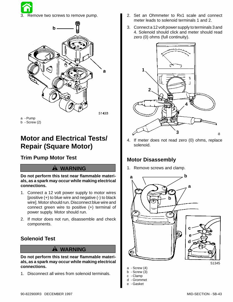
3. Remove two screws to remove pump.
a - Pumpb - Screw (2)
Motor and Electrical Tests/Repair (Square Motor)Trim Pump Motor Test
WARNINGDo not perform this test near flammable materi-als, as a spark may occur while making electricalconnections.1. Connect a 12 volt power supply to motor wires
[positive (+) to blue wire and negative (-) to blackwire]. Motor should run. Disconnect blue wire andconnect green wire to positive (+) terminal ofpower supply. Motor should run.
2. If motor does not run, disassemble and checkcomponents.
Solenoid Test
WARNINGDo not perform this test near flammable materi-als, as a spark may occur while making electricalconnections.1. Disconnect all wires from solenoid terminals.
2. Set an Ohmmeter to Rx1 scale and connectmeter leads to solenoid terminals 1 and 2.
3. Connect a 12 volt power supply to terminals 3 and4. Solenoid should click and meter should readzero (0) ohms (full continuity).
51338
1
2
4
34. If meter does not read zero (0) ohms, replace
solenoid.
Motor Disassembly1. Remove screws and clamp.
51345
a b
a
b
c
de
a - Screw (4)b - Screw (3)c - Clampd - Grommete - Gasket
5B-44 - MID-SECTION 90-822900R3 DECEMBER 1997
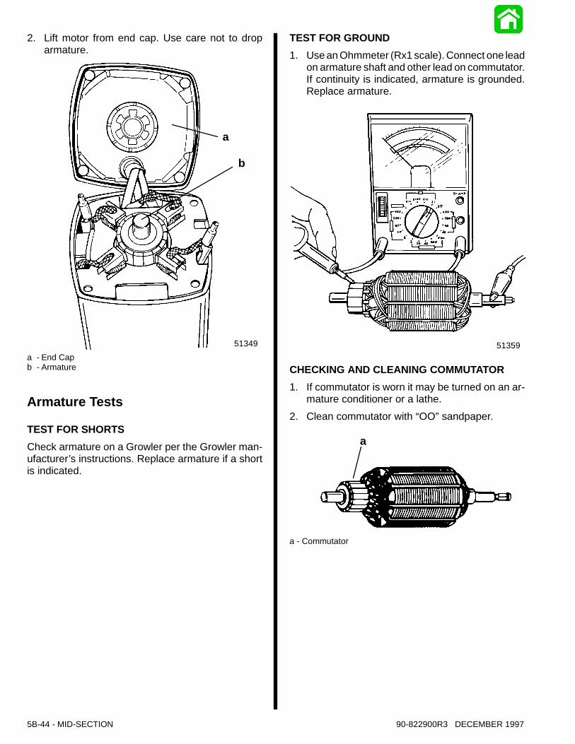
2. Lift motor from end cap. Use care not to droparmature.
51349
a
b
a - End Capb - Armature
Armature Tests
TEST FOR SHORTSCheck armature on a Growler per the Growler man-ufacturer’s instructions. Replace armature if a shortis indicated.
TEST FOR GROUND1. Use an Ohmmeter (Rx1 scale). Connect one lead
on armature shaft and other lead on commutator.If continuity is indicated, armature is grounded.Replace armature.
51359
CHECKING AND CLEANING COMMUTATOR1. If commutator is worn it may be turned on an ar-
mature conditioner or a lathe.2. Clean commutator with “OO”sandpaper.
a
a - Commutator
90-822900R3 DECEMBER 1997 MID-SECTION - 5B-45
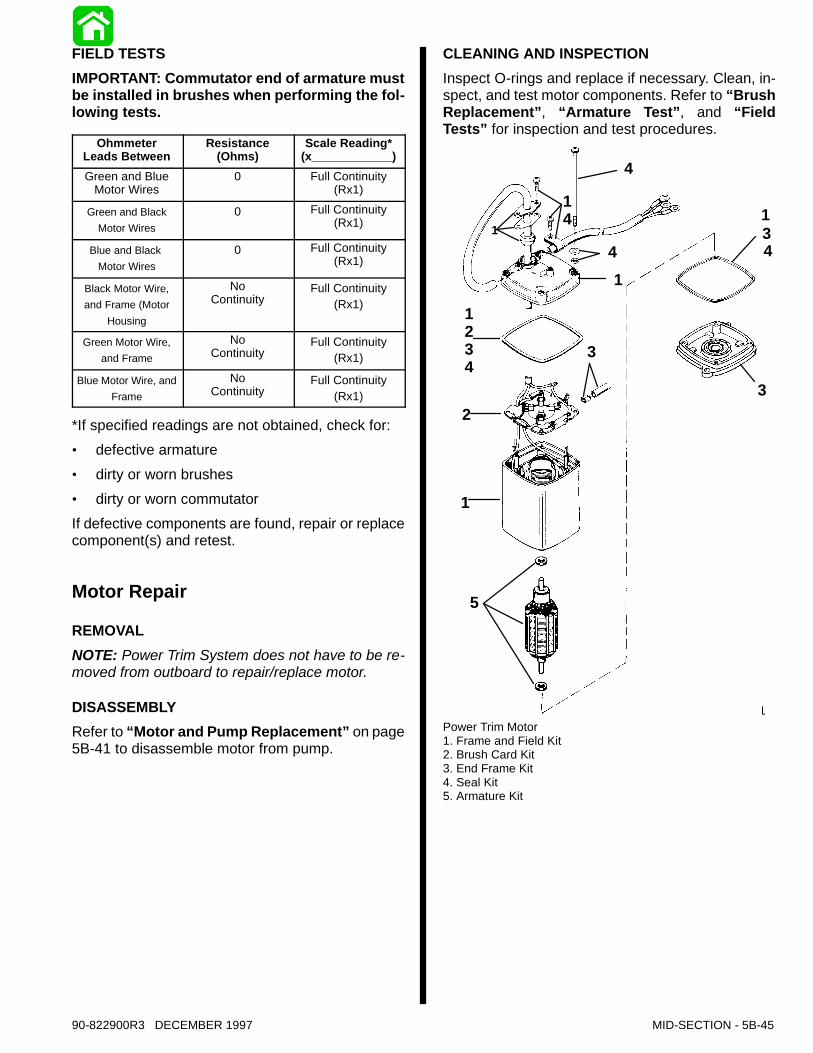
FIELD TESTSIMPORTANT: Commutator end of armature mustbe installed in brushes when performing the fol-lowing tests.
OhmmeterLeads Between
Resistance(Ohms)
Scale Reading*(x____________)
Green and BlueMotor Wires
0 Full Continuity(Rx1)
Green and BlackMotor Wires
0 Full Continuity(Rx1)
Blue and BlackMotor Wires
0 Full Continuity(Rx1)
Black Motor Wire,and Frame (Motor
Housing
NoContinuity
Full Continuity(Rx1)
Green Motor Wire,and Frame
NoContinuity
Full Continuity(Rx1)
Blue Motor Wire, andFrame
NoContinuity
Full Continuity(Rx1)
*If specified readings are not obtained, check for:· defective armature· dirty or worn brushes· dirty or worn commutatorIf defective components are found, repair or replacecomponent(s) and retest.
Motor Repair
REMOVALNOTE: Power Trim System does not have to be re-moved from outboard to repair/replace motor.
DISASSEMBLYRefer to “Motor and Pump Replacement”on page5B-41 to disassemble motor from pump.
CLEANING AND INSPECTIONInspect O-rings and replace if necessary. Clean, in-spect, and test motor components. Refer to “BrushReplacement”, “Armature Test”, and “FieldTests” for inspection and test procedures.
51371
14
1
1234
2
1
4
41
5
3
134
3
Power Trim Motor1. Frame and Field Kit2. Brush Card Kit3. End Frame Kit4. Seal Kit5. Armature Kit

5B-46 - MID-SECTION 90-822900R3 DECEMBER 1997
BRUSH REPLACEMENT1. Brush replacement is required if brushes are
pitted, chipped, or if distance (a) between thebrush pigtail and end of brush holder slot is 1/16in. or less. Check distance with armature in-stalled.
51350
a
a - 1/16 in.
2. To replace brush card, remove insulators.
51350
aa
a - Insulators
3. Remove metal connectors.
51351
a
a
a - Metal Connectors
4. Install new brush card.5. Crimp new metal connectors onto wires.6. Insulate connections with heat shrink tubing.
ReassemblyIMPORTANT: Components must be clean. Anydebris in power trim system can cause system tomalfunction.1. Install armature in motor housing.
51349
a
b
a - Motor Housingb - Armature (Spread brushes to insert commutator.)
90-822900R3 DECEMBER 1997 MID-SECTION - 5B-47
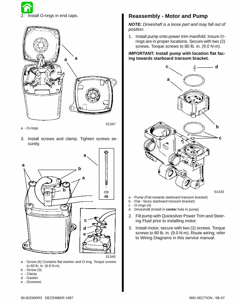
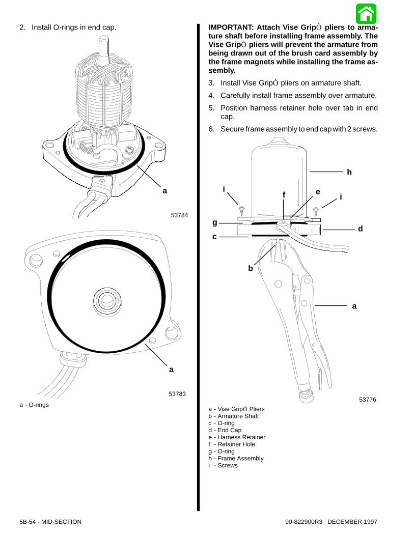
2. Install O-rings in end caps.
51347
aa
a - O-rings
3. Install screws and clamp. Tighten screws se-curely.
51357
51345
a
b
a
cde
ab
a - Screw (4) Contains flat washer and O-ring. Torque screwsto 60 lb. in. (6.8 N·m).
b - Screw (3)c - Clampd - Gaskete - Grommet
Reassembly - Motor and PumpNOTE: Driveshaft is a loose part and may fall out ofposition.1. Install pump onto power trim manifold. Insure O-
rings are in proper locations. Secure with two (2)screws. Torque screws to 80 lb. in. (9.0 N·m).
IMPORTANT: Install pump with location flat fac-ing towards starboard transom bracket.
51433
c
a
d
b
c
a - Pump (Flat towards starboard transom bracket)b - Flat - faces starboard transom bracket)c - O-rings (4)d - Driveshaft (Install in center hole in pump)
2. Fill pump with Quicksilver Power Trim and Steer-ing Fluid prior to installing motor.
3. Install motor, secure with two (2) screws. Torquescrews to 80 lb. in. (9.0 N·m). Route wiring; referto Wiring Diagrams in this service manual.
5B-48 - MID-SECTION 90-822900R3 DECEMBER 1997
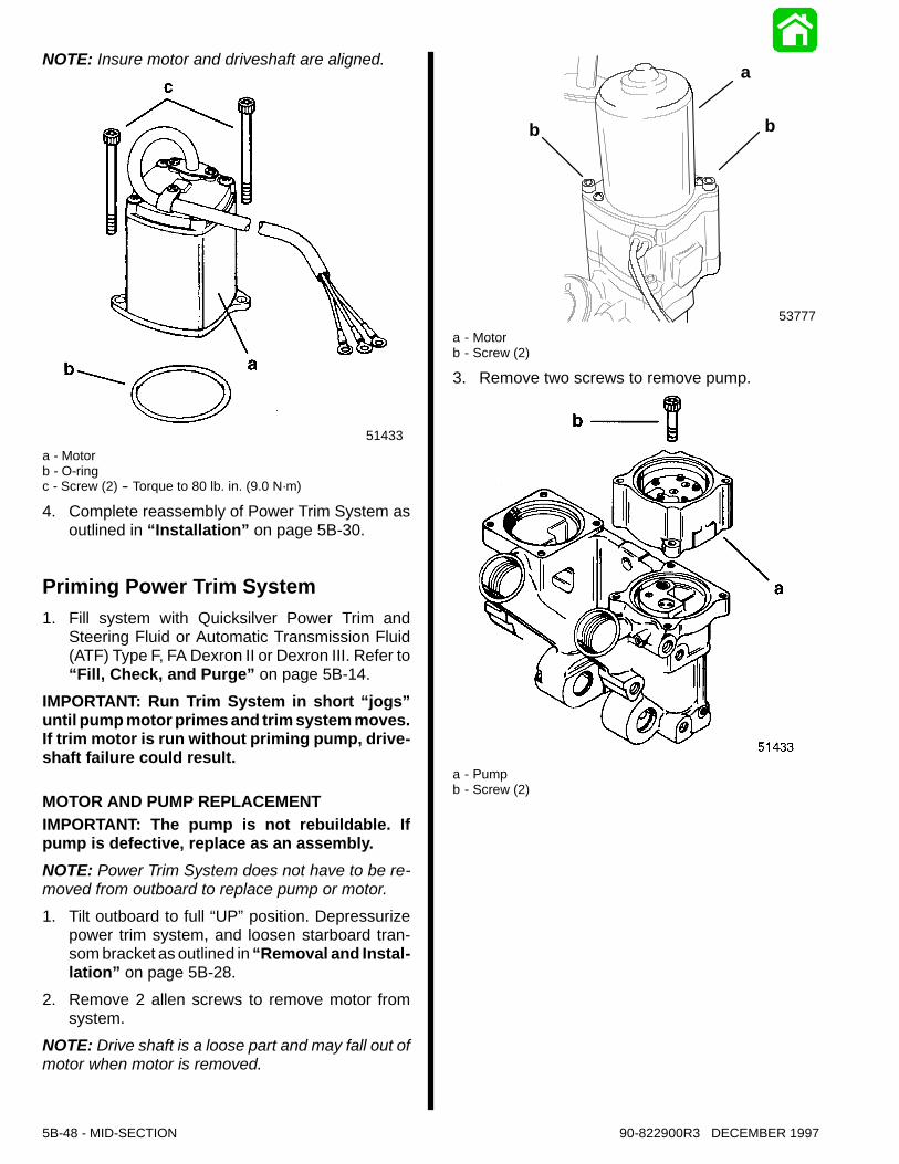
NOTE: Insure motor and driveshaft are aligned.
51433a - Motorb - O-ringc - Screw (2) -- Torque to 80 lb. in. (9.0 N·m)
4. Complete reassembly of Power Trim System asoutlined in “Installation” on page 5B-30.
Priming Power Trim System1. Fill system with Quicksilver Power Trim and
Steering Fluid or Automatic Transmission Fluid(ATF) Type F, FA Dexron II or Dexron III. Refer to“Fill, Check, and Purge” on page 5B-14.
IMPORTANT: Run Trim System in short “jogs”until pump motor primes and trim system moves.If trim motor is run without priming pump, drive-shaft failure could result.
MOTOR AND PUMP REPLACEMENTIMPORTANT: The pump is not rebuildable. Ifpump is defective, replace as an assembly.NOTE: Power Trim System does not have to be re-moved from outboard to replace pump or motor.1. Tilt outboard to full “UP”position. Depressurize
power trim system, and loosen starboard tran-som bracket as outlined in “Removal and Instal-lation” on page 5B-28.
2. Remove 2 allen screws to remove motor fromsystem.
NOTE: Drive shaft is a loose part and may fall out ofmotor when motor is removed.
53777
b b
a
a - Motorb - Screw (2)
3. Remove two screws to remove pump.
a - Pumpb - Screw (2)
90-822900R3 DECEMBER 1997 MID-SECTION - 5B-49
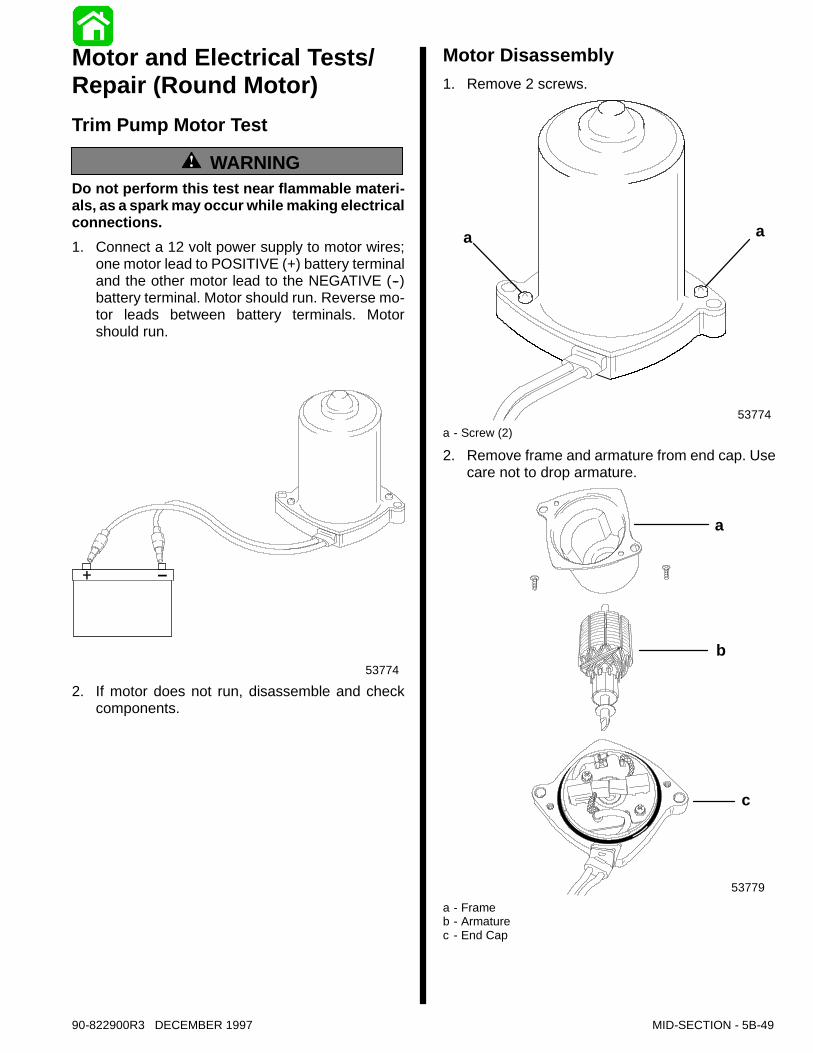
Motor and Electrical Tests/Repair (Round Motor)Trim Pump Motor Test
WARNINGDo not perform this test near flammable materi-als, as a spark may occur while making electricalconnections.1. Connect a 12 volt power supply to motor wires;
one motor lead to POSITIVE (+) battery terminaland the other motor lead to the NEGATIVE (--)battery terminal. Motor should run. Reverse mo-tor leads between battery terminals. Motorshould run.
53774
2. If motor does not run, disassemble and checkcomponents.
Motor Disassembly1. Remove 2 screws.
53774
a a
a - Screw (2)
2. Remove frame and armature from end cap. Usecare not to drop armature.
53779
a
b
c
a - Frameb - Armaturec - End Cap
5B-50 - MID-SECTION 90-822900R3 DECEMBER 1997
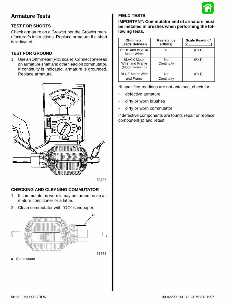
Armature TestsTEST FOR SHORTSCheck armature on a Growler per the Growler man-ufacturer’s instructions. Replace armature if a shortis indicated.
TEST FOR GROUND1. Use an Ohmmeter (Rx1 scale). Connect one lead
on armature shaft and other lead on commutator.If continuity is indicated, armature is grounded.Replace armature.
53786
CHECKING AND CLEANING COMMUTATOR1. If commutator is worn it may be turned on an ar-
mature conditioner or a lathe.2. Clean commutator with “OO”sandpaper.
53775
a
a - Commutator
FIELD TESTSIMPORTANT: Commutator end of armature mustbe installed in brushes when performing the fol-lowing tests.
OhmmeterLeads Between
Resistance(Ohms)
Scale Reading*(x____________)
BLUE and BLACKMotor Wires
0 (Rx1)
BLACK MotorWire, and Frame(Motor Housing)
NoContinuity
(Rx1)
BLUE Motor Wireand Frame
NoContinuity
(Rx1)
*If specified readings are not obtained, check for:· defective armature· dirty or worn brushes· dirty or worn commutatorIf defective components are found, repair or replacecomponent(s) and retest.
90-822900R3 DECEMBER 1997 MID-SECTION - 5B-51
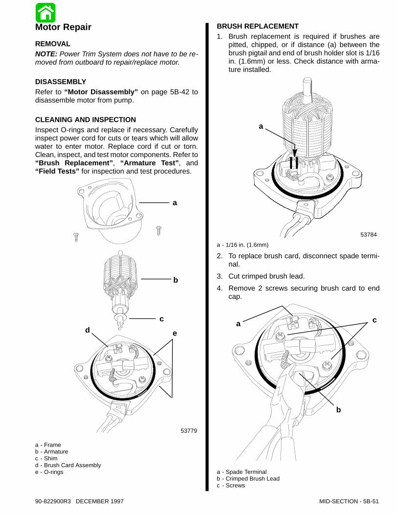
Motor RepairREMOVALNOTE: Power Trim System does not have to be re-moved from outboard to repair/replace motor.
DISASSEMBLYRefer to “Motor Disassembly” on page 5B-42 todisassemble motor from pump.
CLEANING AND INSPECTIONInspect O-rings and replace if necessary. Carefullyinspect power cord for cuts or tears which will allowwater to enter motor. Replace cord if cut or torn.Clean, inspect, and test motor components. Refer to“Brush Replacement”, “Armature Test”, and“Field Tests” for inspection and test procedures.
53779
a
b
cd e
a - Frameb - Armaturec - Shimd - Brush Card Assemblye - O-rings
BRUSH REPLACEMENT1. Brush replacement is required if brushes are
pitted, chipped, or if distance (a) between thebrush pigtail and end of brush holder slot is 1/16in. (1.6mm) or less. Check distance with arma-ture installed.
53784
a
a - 1/16 in. (1.6mm)
2. To replace brush card, disconnect spade termi-nal.
3. Cut crimped brush lead.4. Remove 2 screws securing brush card to end
cap.
a
b
c
a - Spade Terminalb - Crimped Brush Leadc - Screws
5B-52 - MID-SECTION 90-822900R3 DECEMBER 1997
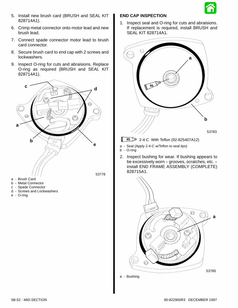
5. Install new brush card (BRUSH and SEAL KIT828714A1).
6. Crimp metal connector onto motor lead and newbrush lead.
7. Connect spade connector motor lead to brushcard connector.
8. Secure brush card to end cap with 2 screws andlockwashers.
9. Inspect O-ring for cuts and abraisions. ReplaceO-ring as required (BRUSH and SEAL KIT828714A1).
53778
c d
eb
a
a - Brush Cardb - Metal Connectorc - Spade Connectord - Screws and Lockwasherse - O-ring
END CAP INSPECTION1. Inspect seal and O-ring for cuts and abraisions.
If replacement is required, install BRUSH andSEAL KIT 828714A1.
53783
a
b
95 2-4-C With Teflon (92-825407A12)
95
a - Seal (Apply 2-4-C w/Teflon to seal lips)b - O-ring
2. Inspect bushing for wear. If bushing appears tobe excessively worn -- grooves, scratches, etc. --install END FRAME ASSEMBLY (COMPLETE)828715A1.
53785
a
a - Bushing

90-822900R3 DECEMBER 1997 MID-SECTION - 5B-53
3. If trim motor is overheated, a thermoswitch lo-cated under brush card will open. Normally, thisswitch will reset itself within 1 minute.
53781
a
a - Thermoswitch
ReassemblyIMPORTANT: Components must be clean. Anydebris in power trim system can cause system tomalfunction.1. Install armature into end cap/brush card assem-
bly.
53779
a
b
c
53784
d
a - Armatureb - Shimc - End Cap Assemblyd - Armature (Spread brushes to install armature into end cap)
5B-54 - MID-SECTION 90-822900R3 DECEMBER 1997
2. Install O-rings in end cap.
53784
a
53783
a
a - O-rings
IMPORTANT: Attach Vise GripÒ pliers to arma-ture shaft before installing frame assembly. TheVise GripÒ pliers will prevent the armature frombeing drawn out of the brush card assembly bythe frame magnets while installing the frame as-sembly.3. Install Vise GripÒ pliers on armature shaft.4. Carefully install frame assembly over armature.5. Position harness retainer hole over tab in end
cap.6. Secure frame assembly to end cap with 2 screws.
53776
i
gc
b
a
d
if e
h
a - Vise GripÒ Pliersb - Armature Shaftc - O-ringd - End Cape - Harness Retainerf - Retainer Holeg - O-ringh - Frame Assemblyi - Screws
90-822900R3 DECEMBER 1997 MID-SECTION - 5B-55
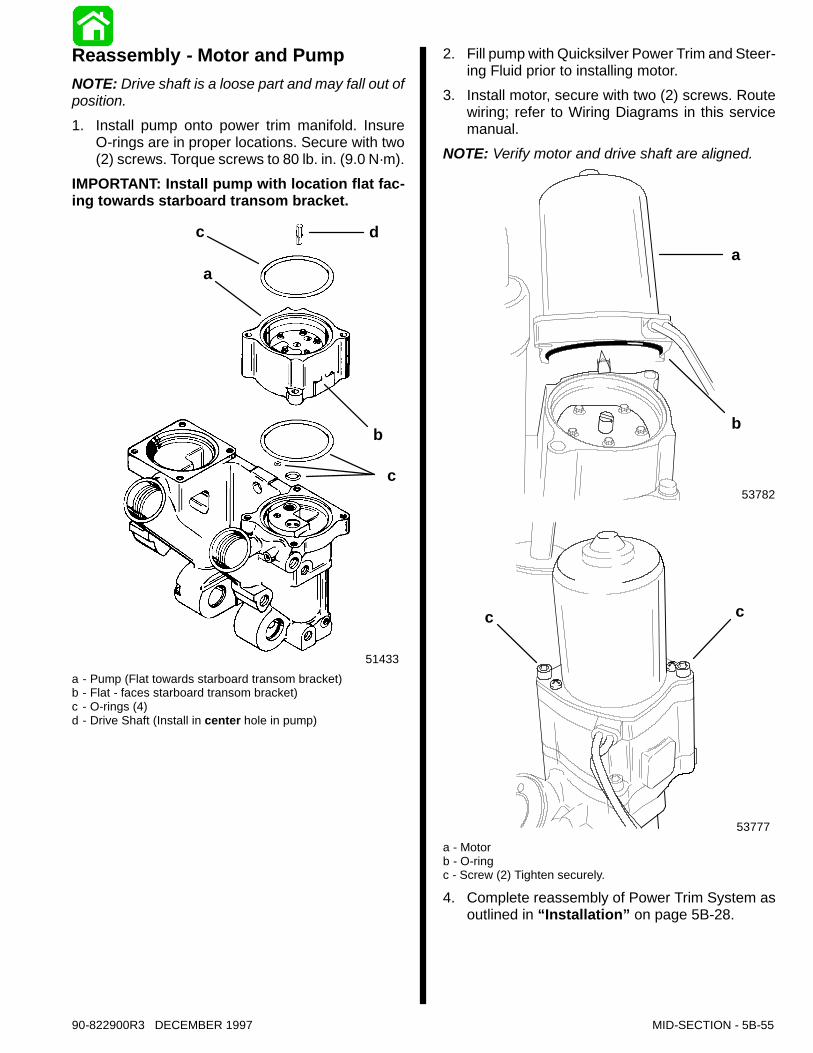
Reassembly - Motor and PumpNOTE: Drive shaft is a loose part and may fall out ofposition.1. Install pump onto power trim manifold. Insure
O-rings are in proper locations. Secure with two(2) screws. Torque screws to 80 lb. in. (9.0 N·m).
IMPORTANT: Install pump with location flat fac-ing towards starboard transom bracket.
51433
dc
a
b
c
a - Pump (Flat towards starboard transom bracket)b - Flat - faces starboard transom bracket)c - O-rings (4)d - Drive Shaft (Install in center hole in pump)
2. Fill pump with Quicksilver Power Trim and Steer-ing Fluid prior to installing motor.
3. Install motor, secure with two (2) screws. Routewiring; refer to Wiring Diagrams in this servicemanual.
NOTE: Verify motor and drive shaft are aligned.
53782
a
b
53777
cc
a - Motorb - O-ringc - Screw (2) Tighten securely.
4. Complete reassembly of Power Trim System asoutlined in “Installation” on page 5B-28.
5B-56 - MID-SECTION 90-822900R3 DECEMBER 1997
Priming Power Trim System1. Fill system with Quicksilver Power Trim and
Steering Fluid or Automatic Transmission Fluid(ATF) Type F,FA, Dexron II or Dexron III. Refer to“Fill, Check, and Purge” on page 5B-14.
IMPORTANT: Run Trim System in short “jogs”until pump motor primes and trim system moves.If trim motor is run without priming pump, driveshaft failure could result.
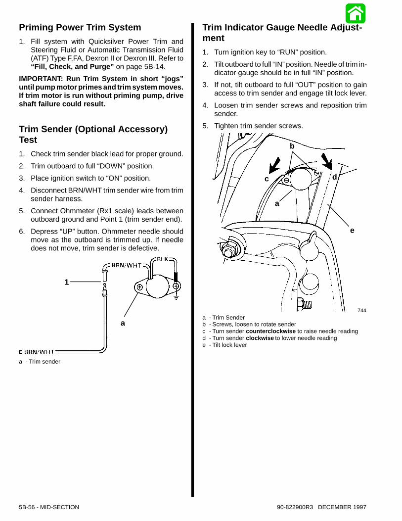
Trim Sender (Optional Accessory)Test1. Check trim sender black lead for proper ground.2. Trim outboard to full “DOWN”position.3. Place ignition switch to “ON”position.4. Disconnect BRN/WHT trim sender wire from trim
sender harness.5. Connect Ohmmeter (Rx1 scale) leads between
outboard ground and Point 1 (trim sender end).6. Depress “UP”button. Ohmmeter needle should
move as the outboard is trimmed up. If needledoes not move, trim sender is defective.
22908
a
1
a - Trim sender
Trim Indicator Gauge Needle Adjust-ment1. Turn ignition key to “RUN”position.2. Tilt outboard to full “IN”position. Needle of trim in-
dicator gauge should be in full “IN”position.3. If not, tilt outboard to full “OUT”position to gain
access to trim sender and engage tilt lock lever.4. Loosen trim sender screws and reposition trim
sender.5. Tighten trim sender screws.
22744
c
b
a
d
e
a - Trim Senderb - Screws, loosen to rotate senderc - Turn sender counterclockwise to raise needle readingd - Turn sender clockwise to lower needle readinge - Tilt lock lever
90-822900R3 DECEMBER 1997 MID-SECTION - 5B-57
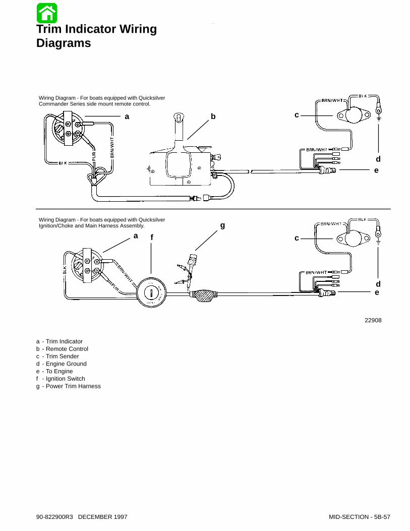
Trim Indicator WiringDiagrams
22908
Wiring Diagram - For boats equipped with QuicksilverCommander Series side mount remote control.
Wiring Diagram - For boats equipped with QuicksilverIgnition/Choke and Main Harness Assembly.
a b c
de
a fg
c
de
a - Trim Indicatorb - Remote Controlc - Trim Senderd - Engine Grounde - To Enginef - Ignition Switchg - Power Trim Harness