powerbook g4 computer - higher...
TRANSCRIPT
D e v e l o p e r N o t e
PowerBook G4 Computer
December 2001
Apple Computer, Inc.© 2000, 2001 Apple Computer, Inc.All rights reserved. No part of this publication may be reproduced, stored in a retrieval system, or transmitted, in any form or by any means, mechanical, electronic, photocopying, recording, or otherwise, without prior written permission of Apple Computer, Inc., with the following exceptions: Any person is hereby authorized to store documentation on a single computer for personal use only and to print copies of documentation for personal use provided that the documentation contains Apple’s copyright notice. The Apple logo is a trademark of Apple Computer, Inc. Use of the “keyboard” Apple logo (Option-Shift-K) for commercial purposes without the prior written consent of Apple may constitute trademark infringement and unfair competition in violation of federal and state laws. No licenses, express or implied, are granted with respect to any of the technology described in this book. Apple retains all intellectual property rights associated with the technology described in this book. This book is intended to assist application developers to develop applications only for Apple-labeled or Apple-licensed computersEvery effort has been made to ensure that the information in this document is accurate. Apple is not responsible for typographical errors.Apple Computer, Inc.1 Infinite LoopCupertino, CA 95014408-996-1010Apple, the Apple logo, FireWire, iMac, Macintosh, and PowerBook are trademarks of Apple Computer, Inc., registered in the United States and other countries.AirPort is a trademark of Apple Computer, Inc.
Adobe is a trademark of Adobe Systems Incorporated or its subsidiaries and may be registered in certain jurisdictions.OpenGL is a registered trademark of Silicon Graphics, Inc. PowerPC is a trademark of International Business Machines Corporation, used under license therefrom.Simultaneously published in the United States and Canada
Even though Apple has reviewed this manual, APPLE MAKES NO WARRANTY OR REPRESENTATION, EITHER EXPRESS OR IMPLIED, WITH RESPECT TO THIS MANUAL, ITS QUALITY, ACCURACY, MERCHANTABILITY, OR FITNESS FOR A PARTICULAR PURPOSE. AS A RESULT, THIS MANUAL IS SOLD “AS IS,” AND YOU, THE PURCHASER, ARE ASSUMING THE ENTIRE RISK AS TO ITS QUALITY AND ACCURACY.
IN NO EVENT WILL APPLE BE LIABLE FOR DIRECT, INDIRECT, SPECIAL, INCIDENTAL, OR CONSEQUENTIAL DAMAGES RESULTING FROM ANY DEFECT OR INACCURACY IN THIS MANUAL, even if advised of the possibility of such damages.
THE WARRANTY AND REMEDIES SET FORTH ABOVE ARE EXCLUSIVE AND IN LIEU OF ALL OTHERS, ORAL OR WRITTEN, EXPRESS OR IMPLIED. No Apple dealer, agent, or employee is authorized to make any modification, extension, or addition to this warranty.
Some states do not allow the exclusion or limitation of implied warranties or liability for incidental or consequential damages, so the above limitation or exclusion may not apply to you. This warranty gives you specific legal rights, and you may also have other rights which vary from state to state.
Contents
Preface About This Developer Note 9
Contents of This Note 9
Chapter 1 Introduction 11
Features 11Appearance 13Peripheral Devices 15System Software 16
Open Firmware 16Machine Identification 17Power Saving Modes 17
Chapter 2 Architecture 19
Block Diagram and Buses 19Block Diagram 19Main ICs and Buses 21
Microprocessor and Cache 21PowerPC G4 Microprocessor 21Level-2 Cache 22
Memory Controller and Bus Bridge 22System RAM 23Boot ROM 23FireWire Controller 24Ethernet Controller 24Video Display Subsystem 24
I/O Controller 25DMA Support 25Interrupt Support 26USB Interface 26
3 Apple Computer, Inc. December 2001
C O N T E N T S
Ultra ATA/66 Interface 26EIDE Interface 27Modem Support 27Sound Circuitry 27Power Controller 28Infrared Link Interface 28Wireless LAN Interface 28CardBus Controller IC 28
Chapter 3 Devices and Ports 29
USB Ports 29USB Connectors 29Booting from a USB Device 30
FireWire Port 31FireWire Connector 31FireWire Device Programming 33Target Disk Mode 33
Ethernet Port 34Internal Modem 36AirPort Card 36
Data Security 37AirPort Hardware 37AirPort Software 37
Infrared Communication Link 38Hard Disk Drive 38
Hard Disk Dimensions 39Hard Disk Connector 41
Signal Assignments 42ATA Signal Descriptions 43
DVD-ROM/CD-RW Combo drive 44Trackpad 45Keyboard 46
Removing the Keyboard 46Changing the Operation of the Keyboard 46
Keyboard Illustrations 47Using the Fn Key 50
4 Apple Computer, Inc. December 2001
C O N T E N T S
Using the Num Lock Key 50The Function-Keys Checkbox 50Operations of the Function Keys 52The Embedded Keypad 53Other Control Keys 54
Flat Panel Display 55External Monitors 56
Monitors and Picture Sizes 57Monitor Connector 58
External Video Port 60Sound System 61
Sound Inputs 62Built-in Microphone 62Modem Activity Sound Signals 62
Sound Outputs 63Headphone Jack 63Internal Speakers 63
Digitizing Sound 63
Chapter 4 Expansion Features 65
RAM Expansion Slots 65Getting Access to the Slots 66Mechanical Design of RAM SO-DIMMs 67Electrical Design of RAM SO-DIMMs 67
SDRAM Devices 68Configuration of RAM SO-DIMMs 69Address Multiplexing 69
RAM SO-DIMM Electrical Limits 70CardBus Slot 71
Appendix A Supplemental Reference Documents 73
Apple Technotes 733D Graphics 74PowerPC G4 Microprocessor 74
5 Apple Computer, Inc. December 2001
C O N T E N T S
Velocity Engine (AltiVec) 74Mac OS X 75Mac OS 9 76Open Firmware 76RAM Expansion Modules 77PC Card Manager 77ATA Devices 78USB Interface 78FireWire Interface 79Infrared Interface 79Wireless Networks 80
Appendix B Abbreviations 81
Abbreviations and Standard Units 81
6 Apple Computer, Inc. December 2001
Figures and Tables
Chapter 1 Introduction 11
Figure 1-1 Front view of the computer 14Figure 1-2 Back view showing I/O ports 15
Chapter 2 Architecture 19
Figure 2-1 Block diagram 20Table 2-1 Buses supported by the Uni-N IC 23
Chapter 3 Devices and Ports 29
Figure 3-1 USB Type A port 30Figure 3-2 FireWire connector 32Figure 3-3 Maximum dimensions of the internal hard disk 40Figure 3-4 Hard disk connector and location 41Figure 3-5 Keyboard layout 47Figure 3-6 Alternate operations of function and control keys 48Figure 3-7 Embedded numeric keypad operation 49Figure 3-8 Signal pins on the monitor connector 59Figure 3-9 S-video connector 60Table 3-1 Pin assignments on the USB port 30Table 3-2 Pin assignments on the FireWire connector 32Table 3-3 Signals for 10Base-T and 100Base-T operation 34Table 3-4 Signals for 1000Base-T operation 35Table 3-5 Pin assignments on the ATA hard disk connector 42Table 3-6 Signals on the ATA hard disk connector 43Table 3-7 Types of media read and written by the DVD-ROM/CD-RW
drive 45Table 3-8 Setting the default behavior of the function keys 51Table 3-9 The function keys as control buttons 51Table 3-10 Embedded keypad keys 53
7 Apple Computer, Inc. December 2001
F I G U R E S A N D T A B L E S
Table 3-11 Control keys that change 54Table 3-12 Flat panel display resolutions 55Table 3-13 Picture sizes supported 57Table 3-14 Signals on the monitor connector 59Table 3-15 Pin assignments for the S-video output connector 60Table 3-16 Picture sizes for S-video output 61
Chapter 4 Expansion Features 65
Figure 4-1 Interior view showing RAM expansion slots 66Table 4-1 Sizes of RAM expansion modules and devices 69Table 4-2 Types of DRAM devices 70
8 Apple Computer, Inc. December 2001
P R E F A C E
About This Developer Note
This developer note is a technical description of the PowerBook G4 computer. The note provides information about the computer’s internal design, input-output features, and expansion capabilities.
This developer note is intended to help hardware and software developers design products that are compatible with the Macintosh products described here. If you are not already familiar with Macintosh computers or if you would like additional technical information, you may wish to read the supplementary reference documents described in Appendix A.
Contents of This Note
The information in this note is arranged in four chapters and two appendixes.
� Chapter 1, “Introduction” (page 11), introduces the PowerBook G4 computer and describes its features.
� Chapter 2, “Architecture” (page 19), describes the internal logic of the computer, including the main ICs that appear in the block diagram.
� Chapter 3, “Devices and Ports” (page 29), describes the standard I/O ports and the built-in I/O devices.
Note: This developer note has been updated to include information about the latest product features and configurations.
Contents of This Note 9 Apple Computer, Inc. December 2001
P R E F A C E
About This Developer Note
� Chapter 4, “Expansion Features” (page 65), describes the expansion features of interest to developers. It includes development guides for expansion-bay devices, the RAM expansion modules, and the PC Card slot.
� Appendix A (page 73) contains links to supplemental reference documents.
� Appendix B (page 81) is a list of the abbreviations used in this developer note.
10 Contents of This Note Apple Computer, Inc. December 2001
C H A P T E R 1
1 Introduction
This chapter outlines the features of the PowerBook G4 computer.
The latest configurations are different from the previous ones in three respects.
� All configurations have a built-in DVD-ROM/CD-RW Combo drive. See “DVD-ROM/CD-RW Combo drive” (page 44).
� The AirPort Card is included in all configurations. See “AirPort Hardware” (page 37).
� The computer comes with 256 or 512 MB of main memory. See “RAM Expansion Slots” (page 65).
Features
Here is a list of the features of the PowerBook G4 computer. Each feature is described in a later chapter, as indicated in the list.
� Processor: The computer has a PowerPC G4 microprocessor running at a clock speed of 550 or 667 MHz. For more information, see “PowerPC G4 Microprocessor” (page 21).
� System bus: The speed of the system bus is either 133 MHz (in the 667 MHz model) or 100 MHz (in the 550 MHz model).
� Cache location and speed: The L2 cache is now located internal to the processor IC; the clock speed ratio is 1:1. See “Level-2 Cache” (page 22).
Features 11 Apple Computer, Inc. December 2001
C H A P T E R 1
Introduction
� RAM: The computer has two standard SO-DIMM expansion slots for SDRAM modules. The computer comes with 256 or 512 MB of SDRAM installed. See “RAM Expansion Slots” (page 65).
� ROM: The computer has 1 MB of boot ROM used by Open Firmware at startup. For information about the ROM, see “Boot ROM” (page 23). For information about Open Firmware, see “Open Firmware” (page 76).
� Hard disk storage: The computer comes with a built-in hard disk drive with a capacity of 20, 30, or 48 GB. For more information and developer guidelines for alternative hard drives, see “Hard Disk Drive” (page 38).
� Display: 15.2-inch mega-wide screen TFT display (1152 x 768 pixels). See “Flat Panel Display” (page 55).
� External monitor: All configurations support an external video monitor, using the standard VGA video connector for a video monitor and an S-video connector for a PAL or NTSC video monitor. See “External Monitors” (page 56).
� Graphics IC and memory: The ATI Mobility Radeon graphics controller contains 16 MB of DDR memory and operates on the AGP 4x bus. For more information, see “Video Display Subsystem” (page 24).
� Battery bay: The computer has a single battery bay. The battery uses lithium ion cells and provides 55.3 watt-hours at 14.4 V (nominal).
� DVD-ROM/CD-RW Combo drive: All configurations have a built-in DVD-ROM/CD-RW drive. See “DVD-ROM/CD-RW Combo drive” (page 44).
� CardBus slot: The computer has a CardBus slot that accepts one Type I or Type II PC card or a CardBus Card. For more information, see “CardBus Slot” (page 71).
� USB ports: The computer has two USB 1.1 ports for an external keyboard, a mouse, and other USB devices, described in “USB Ports” (page 29).
� FireWire port: The computer has one IEEE-1394a high-speed serial FireWire port, which supports transfer rates of 100, 200, and 400 Mbps. For more information, see “FireWire Port” (page 31).
� Target Disk Mode: The PowerBook G4 computer can act like a FireWire storage device connected to another computer. See “Target Disk Mode” (page 33)
� Modem: The computer has a built-in modem with 56 Kbps data rate and V.90 support. For more information, see “Internal Modem” (page 36).
12 Features Apple Computer, Inc. December 2001
C H A P T E R 1
Introduction
� Ethernet: The computer has a built in Ethernet port with an RJ-45 connector for 10Base-T, 100Base-T, and 1000Base-T operation. For more information, see “Ethernet Port” (page 34).
� Infrared link: The computer has an IrDA infrared link capable of transferring data at up to 4 Mbits per second. For more information, see “Infrared Communication Link” (page 38).
� AirPort Card: An AirPort Card wireless LAN card is standard on all models. For more information, see “AirPort Card” (page 36).
� Sound: The computer has a built-in microphone and stereo speakers as well as a stereo headphone jack. See “Sound System” (page 61)
� Keyboard: The keyboard has an embedded numeric keypad and inverted-T arrow keys. Some of the function keys are used to control the display brightness and speaker volume; the other function keys are programmable by the user. See “Keyboard” (page 46).
� Trackpad: The integrated trackpad includes tap/double tap and drag features. For more information, see “Trackpad” (page 45).
� Weight: The computer weighs 2.4 kg (5.4 pounds).
� Size: The computer is 341 mm (13.4 inches) wide, 241 mm (9.49 inches) deep, and 26.3 mm ( 1.04 inches) thick.
Appearance
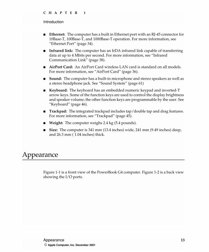
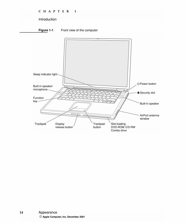
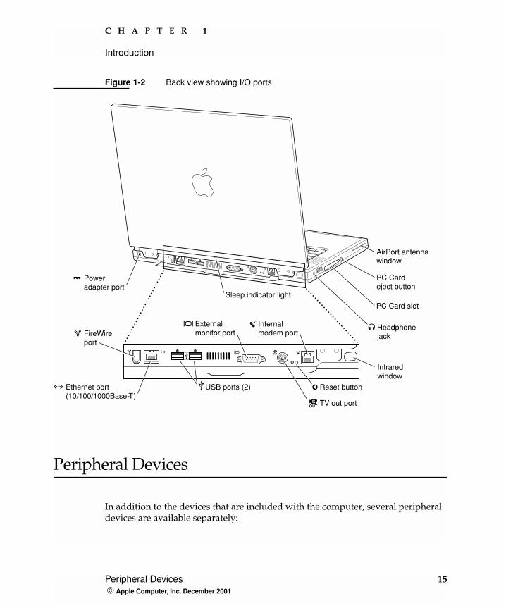
Figure 1-1 is a front view of the PowerBook G4 computer. Figure 1-2 is a back view showing the I/O ports.
Appearance 13 Apple Computer, Inc. December 2001
C H A P T E R 1
Introduction
Figure 1-1 Front view of the computer
®
Built-in speaker
Power button
Security slot
AirPort antennawindow
Built-in speaker/microphone
Sleep indicator light
Functionkey
Trackpadbutton
Displayrelease button
Trackpad Slot-loadingDVD-ROM /CD-RWCombo drive
14 Appearance Apple Computer, Inc. December 2001
C H A P T E R 1
Introduction
Figure 1-2 Back view showing I/O ports
Peripheral Devices
In addition to the devices that are included with the computer, several peripheral devices are available separately:
G
™Æ
W
PC Card slot
PC Cardeject button
AirPort antennawindow
Internalmodem port
Headphonejack
Infraredwindow
USB ports (2)
Poweradapter port
Externalmonitor port
Ethernet port(10/100/1000Base-T)
Reset button
FireWireport
Sleep indicator light
TV out port
1 2
Peripheral Devices 15 Apple Computer, Inc. December 2001
C H A P T E R 1
Introduction
� The PowerBook Intelligent Lithium Ion Battery is available separately as an additional or replacement battery.
� The Apple Portable Power Adapter, which comes with the computer, is also available separately. The adapter can recharge the internal battery in less than five hours while the computer is running or less than three hours while the computer is shut down or in Sleep mode.
� The Apple Pro Keyboard, a full-featured USB keybooard, is available separately.
� The Apple Pro Mouse, an optical USB mouse, is available separately.
� The AirPort Base Station is available separately.
System Software
The PowerBook G4 computer comes with both Mac OS 9.2.2 and Mac OS X version 10.1 installed. Mac OS 9.2 is the default startup system. For the latest information, see the references listed in “Mac OS 9” (page 76) and “Mac OS X” (page 75).
Here are a few items of interest about the system software on the PowerBook G4 computer.
Open FirmwareSystem software on all current Macintosh models uses a design based on Open Firmware. With this approach, the ROM on the main logic board contains only the Open Firmware code needed to initialize the hardware and load an operating system. The rest of the system code is loaded into RAM from disk or from the network. For more information, see the references listed in “Open Firmware” (page 76).
16 System Software Apple Computer, Inc. December 2001
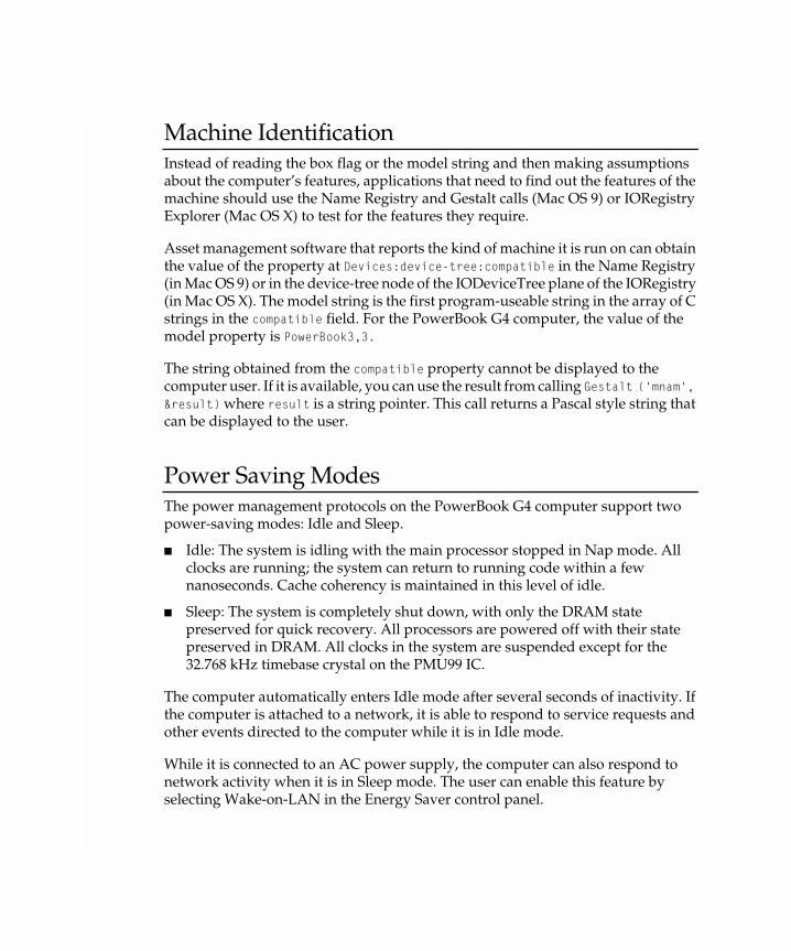
Machine IdentificationInstead of reading the box flag or the model string and then making assumptions about the computer’s features, applications that need to find out the features of the machine should use the Name Registry and Gestalt calls (Mac OS 9) or IORegistry Explorer (Mac OS X) to test for the features they require.
Asset management software that reports the kind of machine it is run on can obtain the value of the property at Devices:device-tree:compatible in the Name Registry (in Mac OS 9) or in the device-tree node of the IODeviceTree plane of the IORegistry (in Mac OS X). The model string is the first program-useable string in the array of C strings in the compatible field. For the PowerBook G4 computer, the value of the model property is PowerBook3,3.
The string obtained from the compatible property cannot be displayed to the computer user. If it is available, you can use the result from calling Gestalt ('mnam', &result) where result is a string pointer. This call returns a Pascal style string that can be displayed to the user.
Power Saving ModesThe power management protocols on the PowerBook G4 computer support two power-saving modes: Idle and Sleep.
� Idle: The system is idling with the main processor stopped in Nap mode. All clocks are running; the system can return to running code within a few nanoseconds. Cache coherency is maintained in this level of idle.
� Sleep: The system is completely shut down, with only the DRAM state preserved for quick recovery. All processors are powered off with their state preserved in DRAM. All clocks in the system are suspended except for the 32.768 kHz timebase crystal on the PMU99 IC.
The computer automatically enters Idle mode after several seconds of inactivity. If the computer is attached to a network, it is able to respond to service requests and other events directed to the computer while it is in Idle mode.
While it is connected to an AC power supply, the computer can also respond to network activity when it is in Sleep mode. The user can enable this feature by selecting Wake-on-LAN in the Energy Saver control panel.
C H A P T E R 1
Introduction
In Sleep mode, the computer consumes less than 1 watt of power. That allows it to meet the Energy Star power-saving standard.
ImportantPeripherals such as PCMCIA cards and USB devices that do not conform to the computer’s power management protocols prevent the computer from switching to Sleep mode and so deny the user the benefits of this energy-saving mode. When such peripherals are attached to the computer, the operating system displays a dialog box to inform the user that the computer no longer meets the Energy Star requirements.
18 System Software Apple Computer, Inc. December 2001
C H A P T E R 2
2 Architecture
This chapter describes the architecture of the PowerBook G4 computer. It includes information about the major components on the main logic board: the microprocessor, the other main ICs, and the buses that connect them to each other and to the I/O interfaces.
Block Diagram and Buses
This section is an overview of the major ICs and buses on the computer’s main logic board.
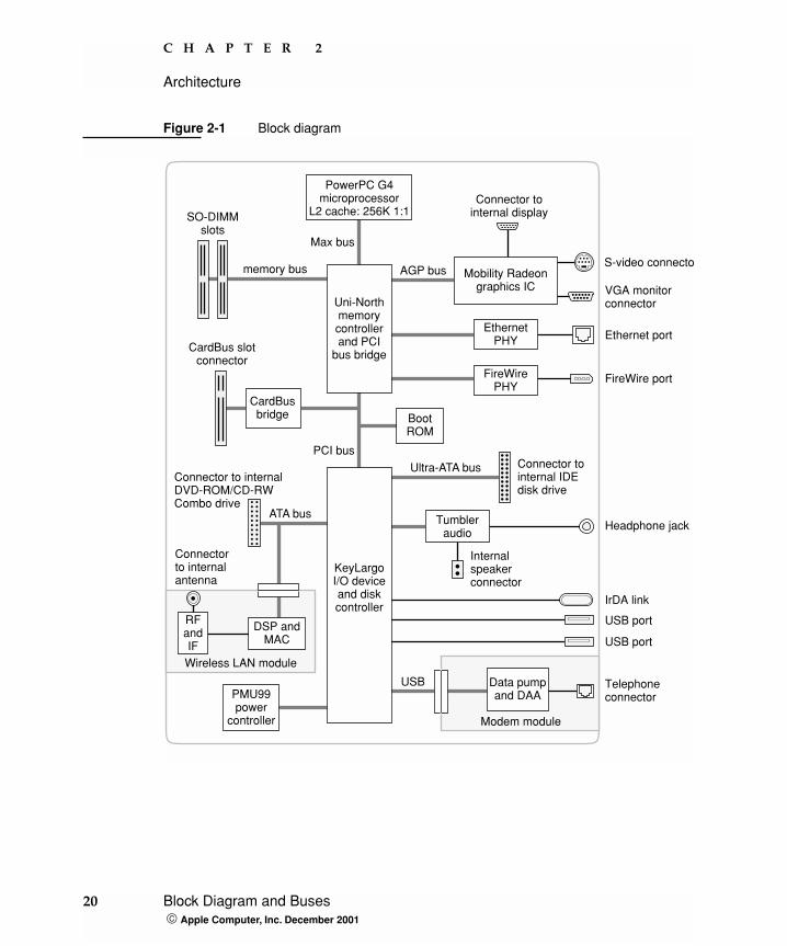
Block DiagramFigure 2-1 is a simplified block diagram of the main logic board. The diagram shows the input and output connectors, the main ICs, and the buses that connect them together.
Block Diagram and Buses 19 Apple Computer, Inc. December 2001
C H A P T E R 2
Architecture
Figure 2-1 Block diagram
memory bus
Ultra-ATA bus
ATA bus
USB
Max bus
Ethernet port
FireWire port
VGA monitorconnector
Connector tointernal display
AGP bus
PCI bus
Telephoneconnector
PowerPC G4microprocessor
L2 cache: 256K 1:1
Uni-Northmemorycontrollerand PCI
bus bridge
PMU99power
controller
BootROM
EthernetPHY
FireWirePHY
Mobility Radeongraphics IC
USB port
USB port
SO-DIMMslots
Connector tointernal IDEdisk drive
Modem module
Data pumpand DAA
DSP andMAC
KeyLargoI/O deviceand diskcontroller
Wireless LAN module
RFandIF
Connectorto internalantenna
S-video connector
Connector to internalDVD-ROM/CD-RWCombo drive
IrDA link
CardBus slotconnector
CardBusbridge
Headphone jackTumbleraudio
Internalspeakerconnector
20 Block Diagram and Buses Apple Computer, Inc. December 2001
Main ICs and BusesThe architecture of the PowerBook G4 computer is designed around the PowerPC G4 microprocessor and two custom ICs: the Uni-N memory controller and bus bridge, and the KeyLargo I/O device controller. Those three ICs occupy the center of the block diagram.
The PowerPC G4 microprocessor is connected to the Uni-N memory controller and bus bridge IC by a MaxBus bus. The bus clock speed is 133 MHz on the 667-MHz model and 100 MHz on the 550-MHz model. The Uni-N IC has other buses that connect with the KeyLargo IC, the main system RAM, and the graphics IC. The buses implemented by the Uni-N IC are summarized in Table 2-1, which is in the section “Memory Controller and Bus Bridge” (page 22).
The Uni-N IC is connected to the KeyLargo I/O controller IC by a 32-bit PCI bus with a bus clock speed of 33 MHz. That bus also connects to the Boot ROM and the CardBus controller. The KeyLargo IC has other buses that connect with the hard disk drive and the DVD-ROM/CD-RW Combo drive, the power controller IC, the sound IC, the internal modem module, and the wireless LAN module.
Each of the components listed here is described in one of the following sections.
Microprocessor and Cache
The microprocessor communicates with the rest of the system by way of a 64-bit MaxBus bus to the Uni-N IC. The microprocessor has a separate bus to its internal second-level cache.
PowerPC G4 MicroprocessorThe PowerPC G4 microprocessor used in the Power Mac G4 computer has many powerful features, including a new pipelined system bus that is more efficient than the system bus on the PowerPC G3 microprocessors. The new bus design, called MaxBus, allows for much greater efficiency of bus utilization than was possible with the previous design.
Features of the PowerPC G4 include:
C H A P T E R 2
Architecture
� 32-bit PowerPC implementation
� superscalar PowerPC core
� Velocity Engine (AltiVec technology): 128-bit-wide vector execution unit
� dual 32 KB instruction and data caches (the same as PowerPC G3)
� an on-chip level-2 (L2) cache consisting of 256 KB with a clock speed ratio of 1:1
� high bandwidth MaxBus (also compatible with 60x bus)
� fully symmetric multiprocessing capability
The PowerPC G4 microprocessor in the PowerBook G4 computer runs at a clock speed of 550 or 667 MHz.
Level-2 CacheThe data storage for the L2 cache consists of 256 KB of fast static RAM that is built into the microprocessor chip along with the cache controller. The built-in L2 cache runs at the same clock speed as the microprocessor.
Memory Controller and Bus Bridge
The Uni-N memory controller and bus bridge IC provides cost and performance benefits by combining several functions into a single IC. It contains the memory controller, the PCI bus bridge, the Ethernet and FireWire interfaces, and the AGP interface.
Each of the separate communication channels in the Uni-N IC can operate at its full capacity without degrading the performance of the other channels.
22 Memory Controller and Bus Bridge Apple Computer, Inc. December 2001
C H A P T E R 2
Architecture
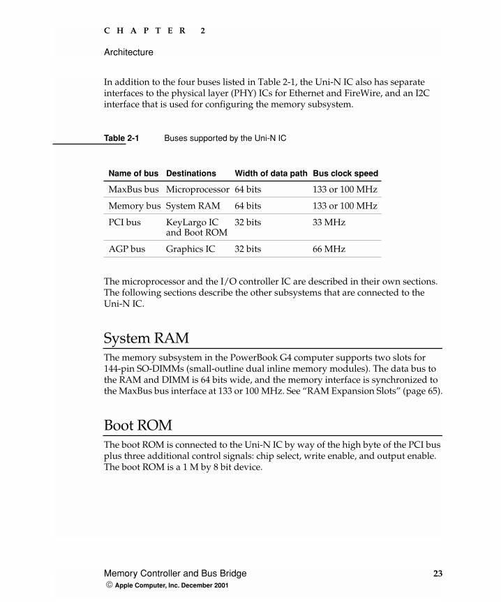
In addition to the four buses listed in Table 2-1, the Uni-N IC also has separate interfaces to the physical layer (PHY) ICs for Ethernet and FireWire, and an I2C interface that is used for configuring the memory subsystem.
The microprocessor and the I/O controller IC are described in their own sections. The following sections describe the other subsystems that are connected to the Uni-N IC.
System RAMThe memory subsystem in the PowerBook G4 computer supports two slots for 144-pin SO-DIMMs (small-outline dual inline memory modules). The data bus to the RAM and DIMM is 64 bits wide, and the memory interface is synchronized to the MaxBus bus interface at 133 or 100 MHz. See “RAM Expansion Slots” (page 65).
Boot ROMThe boot ROM is connected to the Uni-N IC by way of the high byte of the PCI bus plus three additional control signals: chip select, write enable, and output enable. The boot ROM is a 1 M by 8 bit device.
Table 2-1 Buses supported by the Uni-N IC
Name of bus Destinations Width of data path Bus clock speed
MaxBus bus Microprocessor 64 bits 133 or 100 MHz
Memory bus System RAM 64 bits 133 or 100 MHz
PCI bus KeyLargo ICand Boot ROM
32 bits 33 MHz
AGP bus Graphics IC 32 bits 66 MHz
Memory Controller and Bus Bridge 23 Apple Computer, Inc. December 2001
C H A P T E R 2
Architecture
FireWire ControllerThe Uni-N IC includes an IEEE 1394a FireWire controller with a maximum data rate of 400 Mbits (50MB) per second. The Uni-N IC provides DMA (direct memory access) support for the FireWire interface.
The controller in the Uni-N IC implements the FireWire link layer. A physical layer IC, called a PHY, implements the electrical signalling protocol of the FireWire interface and provides the electrical signals to the port. For more information, see “FireWire Connector” (page 31).
Ethernet Controller The Uni-N IC includes an Ethernet media access controller (MAC) that implements the Link layer. The Uni-N IC provides DB-DMA support for the Ethernet interface.
The Ethernet controller in the Uni-N IC is connected to a PHY interface IC that provides the electrical signals to the port. The PHY is capable of operating in either 10Base-T, 100Base-TX, or 1000Base-T mode: The actual speed of the link is automatically negotiated by the PHY and the bridge or router to which it is connected, in compliance with IEEE 802.3u-1995. For more information, see “Ethernet Port” (page 34).
The PHY supports Auto-MDIX, which allows the use of straight-through cables in crossover situations (and conversely). For more information, see “Ethernet Port” (page 34).
Video Display Subsystem The graphics controller IC is an ATI Mobility Radeon. Along with 16 MB of on-chip DDR memory, the graphics IC contains 2D and 3D acceleration engines, front-end and back-end scalers, a CRT controller, and an AGP 4X bus interface with bus master capability.
The features of the Mobility Radeon include
� support for 16 MB of DDR video memory
� 2D and 3D graphics acceleration
� video acceleration
24 Memory Controller and Bus Bridge Apple Computer, Inc. December 2001

C H A P T E R 2
Architecture
� support for MPEG decoding
� support for video mirror mode
� support for dual-display mode
� S-video output for a TV monitor
The interface between the graphics IC and the rest of the system is an AGP 4x (accelerated graphics port, quadruple speed) bus on the Uni-N IC. To give the graphics IC fast access to system memory, the AGP bus has separate address and data lines and supports deeply pipelined read and write operations. The AGP bus has 32 data lines and a clock speed of 66 MHz.
The graphics IC uses a graphics address remapping table (GART) to translate AGP logical addresses into physical addresses. The graphics driver software can allocate memory in both the on-chip SDRAM and the main memory.
The graphics IC supports the built-in flat-panel display and an external monitor. The external monitor can either mirror the built-in display or show additional desktop space (dual-display mode). For information about the displays and supported resolutions, see “Flat Panel Display” (page 55) and “External Monitors” (page 56).
I/O Controller
The I/O controller IC in the PowerBook G4 computer is a custom IC called KeyLargo. It provides the interface and control signals for the following devices:
DMA SupportThe KeyLargo IC provides DB-DMA (descriptor-based direct memory access) support for the following I/O channels:
� Ultra DMA ATA interface to the the internal hard drive
� modem slot interface to the built-in modem
Note: In the device tree, the I/O controller is named “mac-io”.
I/O Controller 25 Apple Computer, Inc. December 2001
C H A P T E R 2
Architecture
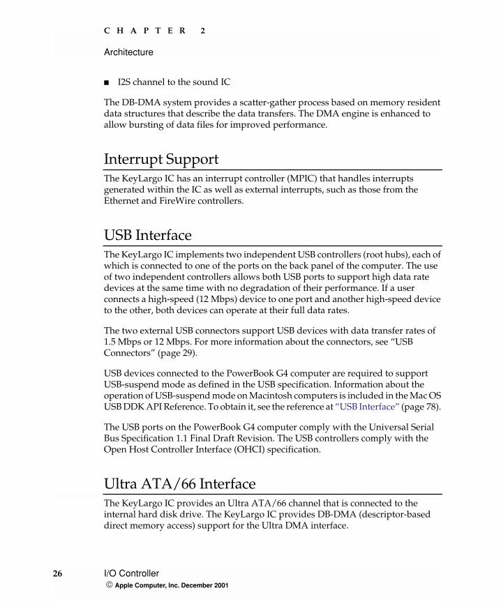
� I2S channel to the sound IC
The DB-DMA system provides a scatter-gather process based on memory resident data structures that describe the data transfers. The DMA engine is enhanced to allow bursting of data files for improved performance.
Interrupt SupportThe KeyLargo IC has an interrupt controller (MPIC) that handles interrupts generated within the IC as well as external interrupts, such as those from the Ethernet and FireWire controllers.
USB InterfaceThe KeyLargo IC implements two independent USB controllers (root hubs), each of which is connected to one of the ports on the back panel of the computer. The use of two independent controllers allows both USB ports to support high data rate devices at the same time with no degradation of their performance. If a user connects a high-speed (12 Mbps) device to one port and another high-speed device to the other, both devices can operate at their full data rates.
The two external USB connectors support USB devices with data transfer rates of 1.5 Mbps or 12 Mbps. For more information about the connectors, see “USB Connectors” (page 29).
USB devices connected to the PowerBook G4 computer are required to support USB-suspend mode as defined in the USB specification. Information about the operation of USB-suspend mode on Macintosh computers is included in the Mac OS USB DDK API Reference. To obtain it, see the reference at “USB Interface” (page 78).
The USB ports on the PowerBook G4 computer comply with the Universal Serial Bus Specification 1.1 Final Draft Revision. The USB controllers comply with the Open Host Controller Interface (OHCI) specification.
Ultra ATA/66 Interface The KeyLargo IC provides an Ultra ATA/66 channel that is connected to the internal hard disk drive. The KeyLargo IC provides DB-DMA (descriptor-based direct memory access) support for the Ultra DMA interface.
26 I/O Controller Apple Computer, Inc. December 2001
C H A P T E R 2
Architecture
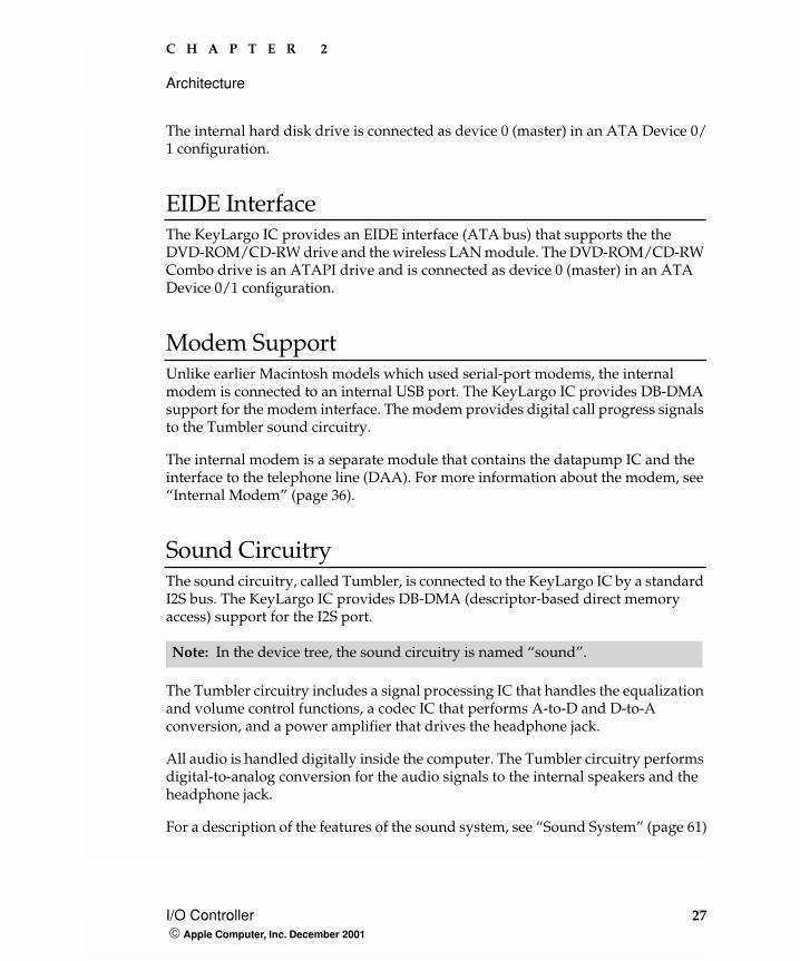
The internal hard disk drive is connected as device 0 (master) in an ATA Device 0/1 configuration.
EIDE InterfaceThe KeyLargo IC provides an EIDE interface (ATA bus) that supports the the DVD-ROM/CD-RW drive and the wireless LAN module. The DVD-ROM/CD-RW Combo drive is an ATAPI drive and is connected as device 0 (master) in an ATA Device 0/1 configuration.
Modem Support Unlike earlier Macintosh models which used serial-port modems, the internal modem is connected to an internal USB port. The KeyLargo IC provides DB-DMA support for the modem interface. The modem provides digital call progress signals to the Tumbler sound circuitry.
The internal modem is a separate module that contains the datapump IC and the interface to the telephone line (DAA). For more information about the modem, see “Internal Modem” (page 36).
Sound Circuitry The sound circuitry, called Tumbler, is connected to the KeyLargo IC by a standard I2S bus. The KeyLargo IC provides DB-DMA (descriptor-based direct memory access) support for the I2S port.
The Tumbler circuitry includes a signal processing IC that handles the equalization and volume control functions, a codec IC that performs A-to-D and D-to-A conversion, and a power amplifier that drives the headphone jack.
All audio is handled digitally inside the computer. The Tumbler circuitry performs digital-to-analog conversion for the audio signals to the internal speakers and the headphone jack.
For a description of the features of the sound system, see “Sound System” (page 61)
Note: In the device tree, the sound circuitry is named “sound”.
I/O Controller 27 Apple Computer, Inc. December 2001
C H A P T E R 2
Architecture
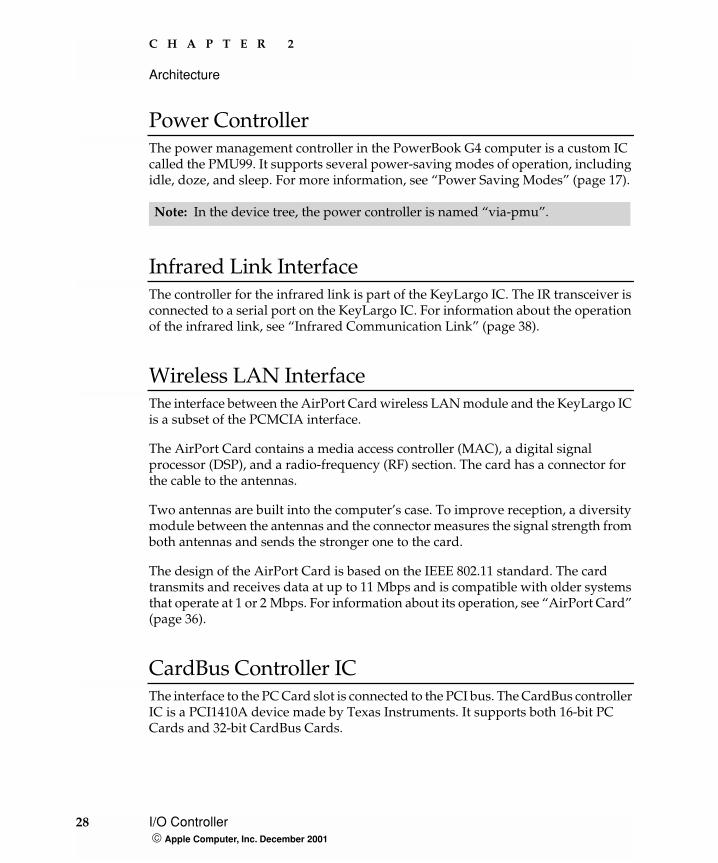
Power ControllerThe power management controller in the PowerBook G4 computer is a custom IC called the PMU99. It supports several power-saving modes of operation, including idle, doze, and sleep. For more information, see “Power Saving Modes” (page 17).
Infrared Link InterfaceThe controller for the infrared link is part of the KeyLargo IC. The IR transceiver is connected to a serial port on the KeyLargo IC. For information about the operation of the infrared link, see “Infrared Communication Link” (page 38).
Wireless LAN InterfaceThe interface between the AirPort Card wireless LAN module and the KeyLargo IC is a subset of the PCMCIA interface.
The AirPort Card contains a media access controller (MAC), a digital signal processor (DSP), and a radio-frequency (RF) section. The card has a connector for the cable to the antennas.
Two antennas are built into the computer’s case. To improve reception, a diversity module between the antennas and the connector measures the signal strength from both antennas and sends the stronger one to the card.
The design of the AirPort Card is based on the IEEE 802.11 standard. The card transmits and receives data at up to 11 Mbps and is compatible with older systems that operate at 1 or 2 Mbps. For information about its operation, see “AirPort Card” (page 36).
CardBus Controller ICThe interface to the PC Card slot is connected to the PCI bus. The CardBus controller IC is a PCI1410A device made by Texas Instruments. It supports both 16-bit PC Cards and 32-bit CardBus Cards.
Note: In the device tree, the power controller is named “via-pmu”.
28 I/O Controller Apple Computer, Inc. December 2001
C H A P T E R 3
3 Devices and Ports
This chapter describes both the built-in I/O devices and the ports for connecting external I/O devices. Each of the following sections describes an I/O port or device.
USB Ports
The PowerBook G4 computer has two external USB 1.1 ports that can be used to connect additional I/O devices such as a USB mouse, printers, scanners, and low-speed storage devices.
The USB ports on the PowerBook G4 computer comply with the Universal Serial Bus Specification 1.1 Final Draft Revision. For more information about USB on the Macintosh computer, consult the references at “USB Interface” (page 78).
USB ConnectorsThe USB ports use USB Type A connectors, which have four pins each. Two of the pins are used for power and two for data. Figure 3-1 is an illustration of a Type A port and matching connector. Table 3-1 shows the pin assignments.
USB Ports 29 Apple Computer, Inc. December 2001
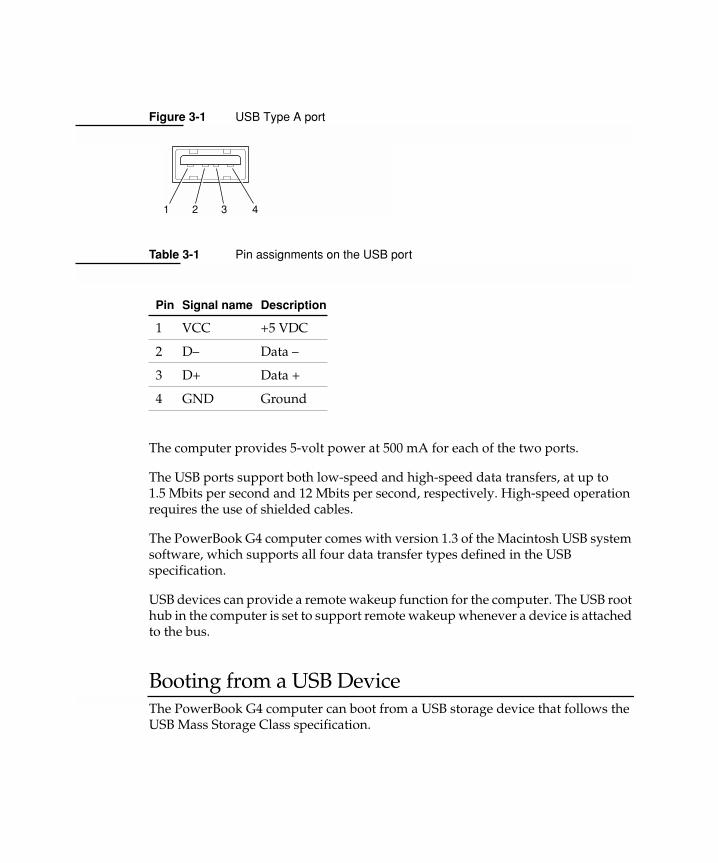
Figure 3-1 USB Type A port
The computer provides 5-volt power at 500 mA for each of the two ports.
The USB ports support both low-speed and high-speed data transfers, at up to 1.5 Mbits per second and 12 Mbits per second, respectively. High-speed operation requires the use of shielded cables.
The PowerBook G4 computer comes with version 1.3 of the Macintosh USB system software, which supports all four data transfer types defined in the USB specification.
USB devices can provide a remote wakeup function for the computer. The USB root hub in the computer is set to support remote wakeup whenever a device is attached to the bus.
Booting from a USB DeviceThe PowerBook G4 computer can boot from a USB storage device that follows the USB Mass Storage Class specification.
Table 3-1 Pin assignments on the USB port
Pin Signal name Description
1 VCC +5 VDC
2 D– Data –
3 D+ Data +
4 GND Ground
1 32 4
C H A P T E R 3
Devices and Ports
Class drivers are software components that are able to communicate with many USB devices of a particular kind. If the appropriate class driver is present, any number of compliant devices can be plugged in and start working immediately without the need to install additional software. The Mac OS for the PowerBook G4 computer includes USB Mass Storage Support 2.0, a class driver that supports devices that meet the USB Mass Storage Class specification.
FireWire Port
The PowerBook G4 computer has one external FireWire IEEE 1394a port. The FireWire port
� supports serial I/O at 100, 200, and 400 Mbps (megabits per second)
� provides up to 6 watts of power when the computer system is on
� supports booting the system from a mass storage device
� supports target disk mode
The FireWire hardware and software provided with the PowerBook G4 computer are capable of all asynchronous and isochronous transfers defined by IEEE standard 1394a.
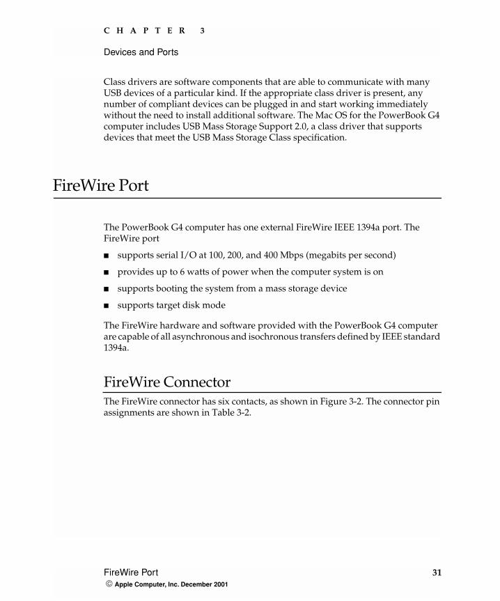
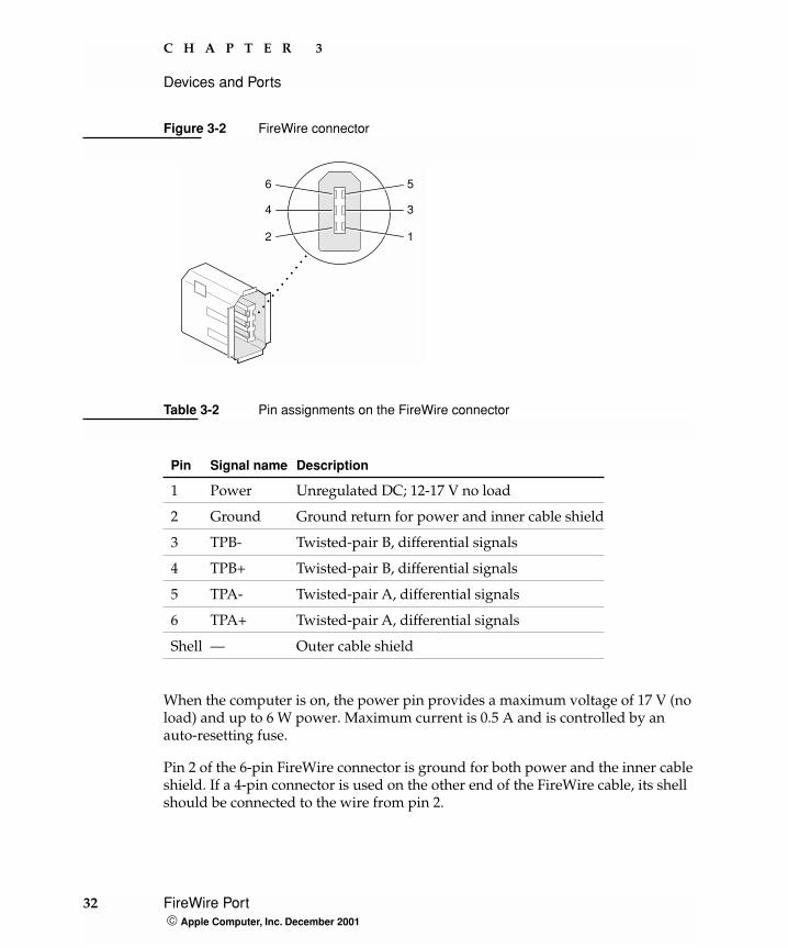
FireWire ConnectorThe FireWire connector has six contacts, as shown in Figure 3-2. The connector pin assignments are shown in Table 3-2.
FireWire Port 31 Apple Computer, Inc. December 2001
C H A P T E R 3
Devices and Ports
Figure 3-2 FireWire connector
When the computer is on, the power pin provides a maximum voltage of 17 V (no load) and up to 6 W power. Maximum current is 0.5 A and is controlled by an auto-resetting fuse.
Pin 2 of the 6-pin FireWire connector is ground for both power and the inner cable shield. If a 4-pin connector is used on the other end of the FireWire cable, its shell should be connected to the wire from pin 2.
Table 3-2 Pin assignments on the FireWire connector
Pin Signal name Description
1 Power Unregulated DC; 12-17 V no load
2 Ground Ground return for power and inner cable shield
3 TPB- Twisted-pair B, differential signals
4 TPB+ Twisted-pair B, differential signals
5 TPA- Twisted-pair A, differential signals
6 TPA+ Twisted-pair A, differential signals
Shell — Outer cable shield
1
3
5
2
4
6
32 FireWire Port Apple Computer, Inc. December 2001

C H A P T E R 3
Devices and Ports
The signal pairs are crossed in the cable itself so that pins 5 and 6 at one end of the cable connect with pins 3 and 4 at the other end. When transmitting, pins 3 and 4 carry data and pins 5 and 6 carry clock; when receiving, the reverse is true.
FireWire Device ProgrammingDevelopers of FireWire peripherals are required to provide device drivers. A driver for DV (digital video) is included in QuickTime.
The PowerBook G4 computer can boot from a FireWire storage device that implements SBP-2 (Serial Bus Protocol) with the RBC (reduced block commands) command set. Detailed information is available only under non-disclosure agreement; contact Developer Technical Support at [email protected].
For additional information about the FireWire interface and the Apple APIs for FireWire device control, refer to the resources listed at “FireWire Interface” (page 79).
Target Disk Mode One option at boot time is to put the computer into a mode of operation called Target Disk mode. This mode is similar to SCSI Disk mode on a PowerBook computer equipped with a SCSI port, except it uses a FireWire connection instead of a special SCSI cable.
When the PowerBook G4 computer is in Target Disk mode and connected to another Macintosh computer by a FireWire cable, the PowerBook G4 computer operates like a FireWire mass storage device with the SBP-2 (Serial Bus Protocol) standard. Target Disk mode has two primary uses:
� high-speed data transfer between computers
� diagnosis and repair of a corrupted internal hard drive
The PowerBook G4 computer can operate in Target Disk Mode as long as the other computer has a FireWire port and is running either
� Mac OS X (any version)
� Mac OS 9 with FireWire software 2.3.3 or newer
FireWire Port 33 Apple Computer, Inc. December 2001
C H A P T E R 3
Devices and Ports
To put the computer into Target Disk mode, the user holds down the T key while the computer is starting up. When Open Firmware detects the T key during the boot process, it transfers control to special Open Firmware code.
To take the computer out of Target Disk mode, the user presses the power button.
For more information about Target Disk mode, see the section “Target Mode” in Technote 1189, The Monster Disk Driver Technote. The technote is available on the Technote website at
http://developer.apple.com/technotes/
Ethernet Port
The PowerBook G4 computer has a built-in Ethernet port that supports 10Base-T, 100Base-T, and 1000Base-T transfer rates. In operation, the actual speed of the link is auto-negotiated between the computer’s PHY device and the network bridge or router to which it is connected.
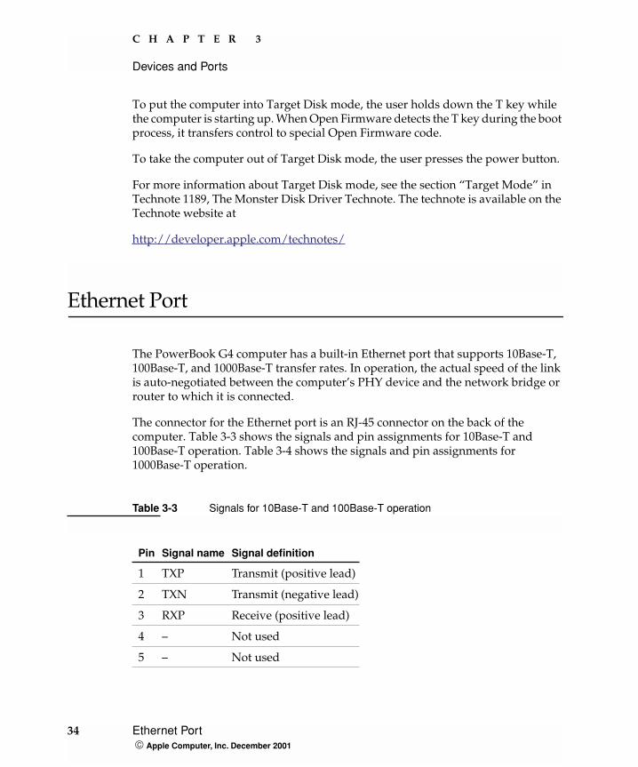
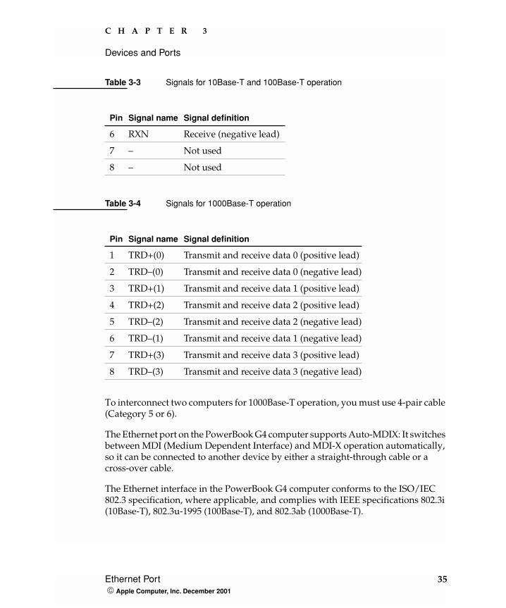
The connector for the Ethernet port is an RJ-45 connector on the back of the computer. Table 3-3 shows the signals and pin assignments for 10Base-T and 100Base-T operation. Table 3-4 shows the signals and pin assignments for 1000Base-T operation.
Table 3-3 Signals for 10Base-T and 100Base-T operation
Pin Signal name Signal definition
1 TXP Transmit (positive lead)
2 TXN Transmit (negative lead)
3 RXP Receive (positive lead)
4 – Not used
5 – Not used
34 Ethernet Port Apple Computer, Inc. December 2001
C H A P T E R 3
Devices and Ports
To interconnect two computers for 1000Base-T operation, you must use 4-pair cable (Category 5 or 6).
The Ethernet port on the PowerBook G4 computer supports Auto-MDIX: It switches between MDI (Medium Dependent Interface) and MDI-X operation automatically, so it can be connected to another device by either a straight-through cable or a cross-over cable.
The Ethernet interface in the PowerBook G4 computer conforms to the ISO/IEC 802.3 specification, where applicable, and complies with IEEE specifications 802.3i (10Base-T), 802.3u-1995 (100Base-T), and 802.3ab (1000Base-T).
6 RXN Receive (negative lead)
7 – Not used
8 – Not used
Table 3-4 Signals for 1000Base-T operation
Pin Signal name Signal definition
1 TRD+(0) Transmit and receive data 0 (positive lead)
2 TRD–(0) Transmit and receive data 0 (negative lead)
3 TRD+(1) Transmit and receive data 1 (positive lead)
4 TRD+(2) Transmit and receive data 2 (positive lead)
5 TRD–(2) Transmit and receive data 2 (negative lead)
6 TRD–(1) Transmit and receive data 1 (negative lead)
7 TRD+(3) Transmit and receive data 3 (positive lead)
8 TRD–(3) Transmit and receive data 3 (negative lead)
Table 3-3 Signals for 10Base-T and 100Base-T operation
Pin Signal name Signal definition
Ethernet Port 35 Apple Computer, Inc. December 2001

C H A P T E R 3
Devices and Ports
Internal Modem
The PowerBook G4 computer comes with a built-in modem. The connector for the modem is an RJ-11 connector on the back of the computer.
The modem has the following features:
� modem bit rates up to 56 Kbps (supports K56flex and V.90 modem standards)
� Group 3 fax modem bit rates up to 14.4 Kbps
The modem is connected to an internal USB port and is a vendor-specific USB device. The modem driver controls the modem hardware and presents a virtual serial port to the operating system and applications. Applications that bypass the operating sysem’s modem driver and communicate directly with the SCC will not work properly.
AirPort Card
The PowerBook G4 computer supports the AirPort Card, an internal wireless LAN module. The AirPort Card is available as a build-to-order option or as a user-installable upgrade through The Apple Store.
By communicating wirelessly with a base station, the AirPort Card can be used for internet access, email access, and file exchange. A base station provides the connection to the internet or the bridge between the wireless signals and a wired LAN or both. The AirPort Base Station has connectors for a wired LAN, a DSL or cable modem, and a standard telephone line using its built-in 56k modem.
AirPort transmits and receives data at speeds up to 11 Mbps, comparable to wired networking speeds. Airport is Wi-Fi Certified, which means it is fully compatible with other devices that follow the IEEE 802.11b standard, including PC's. For more information about Wi-Fi and compatibility, see the reference at “Wireless Networks” (page 80).
36 Internal Modem Apple Computer, Inc. December 2001
C H A P T E R 3
Devices and Ports
Data SecurityAirPort has several features designed to maintain the security of the user’s data.
� The system uses direct-sequence spread-spectrum (DSSS) technology that uses a multi-bit spreading code that effectively scrambles the data for any receiver that lacks the corresponding code.
� The system can use a table of authentic network client ID values to verify each client’s identity before granting access to the network.
� When communicating with a base station, AirPort uses up to 128-bit encryption to encode your data while it is in transit.
� The AirPort Base Station can be configured to act as a firewall, protecting your data from would-be Internet hackers.
� The AirPort Base Station can authenticate users by their unique Ethernet IDs, preventing unauthorized machines from logging into your network. Network administrators can take advantage of RADIUS compatibility, used for authenticating users over a remote server. Smaller networks can offer the same security using a local look-up table located within the base station.
AirPort Hardware The AirPort Card is a wireless LAN module based on the IEEE 802.11 standard and using direct-sequence spread-spectrum (DSSS) technology. It is interoperable with PC-compatible wireless LANs that conform to the 802.11b standard and use DSSS.
Two AirPort antennas are built into the computer’s cover, on either side of the flat-panel display . One antenna is always used for transmitting. Either of the two antennas may be used for receiving. Using a diversity technique, the AirPort Card selects the antenna that gives the best reception.
AirPort Software Software that is provided with the AirPort Card includes
� AirPort Setup Assistant, an easy-to-use program that guides you through the steps necessary to set up the AirPort Card or set up an AirPort Base Station.
� AirPort Application, an application that allows users to switch between wireless networks and to create and join peer-to-peer networks.
AirPort Card 37 Apple Computer, Inc. December 2001
C H A P T E R 3
Devices and Ports
� AirPort Admin Utility, a utility for advanced users and system administrators. With it the user can edit the administrative and advanced settings needed for some advanced configurations.
Infrared Communication Link
The PowerBook G4 computer has a directed infrared (IR) communication link connected internally to a serial port on the KeyLargo IC. When the computer is placed within range of another device with an IR interface, it can send and receive serial data. Other devices with an IR interface include PDAs, some digital cell phones, and some printers.
Operating range is 1 meter, and the devices must be positioned with their IR ports pointed toward each other within about 15 degrees.
The IR link in the PowerBook G4 computer supports the Infrared Data Association (IrDA) standard at up to 4.0 Mbps. The modulation method complies with the IrDA physical layer standard. For more information, see the reference at “Infrared Interface” (page 79).
Hard Disk Drive
The PowerBook G4 computer has an internal hard disk drive with a storage capacity of 20, 30, or 48 GB. The drive has fluid dynamic bearings for quieter operation.
The hard disk drive uses the extended IDE (integrated drive electronics) interface, which is also referred to as the ATA interface. The implementation of the ATA interface on this computer is a subset of the ATA/ATAPI-5 specification (ANSI NCITS 317-1998 AT Attachment - 5with Packet Interface Extension). That specification is maintained by the National Committee on Information Technology Standards (NCITS) Technical Committee T13.
38 Infrared Communication Link Apple Computer, Inc. December 2001
C H A P T E R 3
Devices and Ports
The software that supports the internal hard disk is the same as that in previous PowerBook models with internal IDE drives and includes DMA support. For the latest information about that software, see Technote #1098, ATA Device Software Guide Additions and Corrections. The web page for Technote #1098 includes a link to a downloadable copy of ATA Device Software Guide.
To obtain the reference documents listed here, see the reference links at “ATA Devices” (page 78).
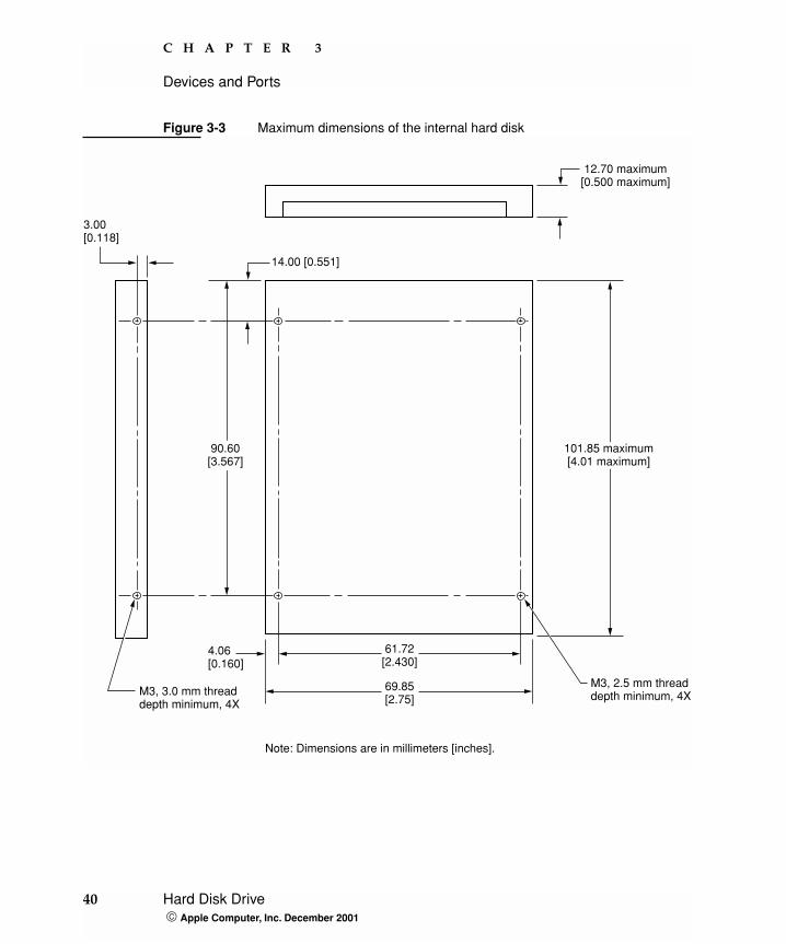
Hard Disk Dimensions Figure 3-3 shows the maximum dimensions of the hard disk and the location of the mounting holes. The hard disk is the same physical size as the ones in the recent PowerBook G3 Series computers: either 9.5 mm (0.37 inches) or 12.7 mm (0.50 inches) high.
The minimum clearance between any conductive components on the drive and the bottom of the mounting envelope is 0.5 mm.
Hard Disk Drive 39 Apple Computer, Inc. December 2001
C H A P T E R 3
Devices and Ports
Figure 3-3 Maximum dimensions of the internal hard disk
3.00[0.118]
4.06[0.160]
61.72[2.430]
69.85[2.75]
M3, 2.5 mm threaddepth minimum, 4X
Note: Dimensions are in millimeters [inches].
12.70 maximum[0.500 maximum]
101.85 maximum[4.01 maximum]
90.60[3.567]
14.00 [0.551]
M3, 3.0 mm threaddepth minimum, 4X
40 Hard Disk Drive Apple Computer, Inc. December 2001
C H A P T E R 3
Devices and Ports
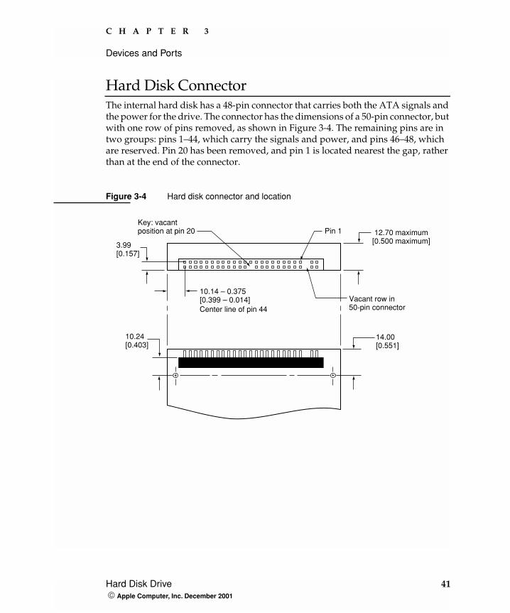
Hard Disk Connector The internal hard disk has a 48-pin connector that carries both the ATA signals and the power for the drive. The connector has the dimensions of a 50-pin connector, but with one row of pins removed, as shown in Figure 3-4. The remaining pins are in two groups: pins 1–44, which carry the signals and power, and pins 46–48, which are reserved. Pin 20 has been removed, and pin 1 is located nearest the gap, rather than at the end of the connector.
Figure 3-4 Hard disk connector and location
3.99[0.157]
10.14 – 0.375[0.399 – 0.014]
Key: vacantposition at pin 20
Vacant row in50-pin connector
Pin 1
Center line of pin 44
10.24[0.403]
14.00[0.551]
12.70 maximum[0.500 maximum]
Hard Disk Drive 41 Apple Computer, Inc. December 2001
C H A P T E R 3
Devices and Ports
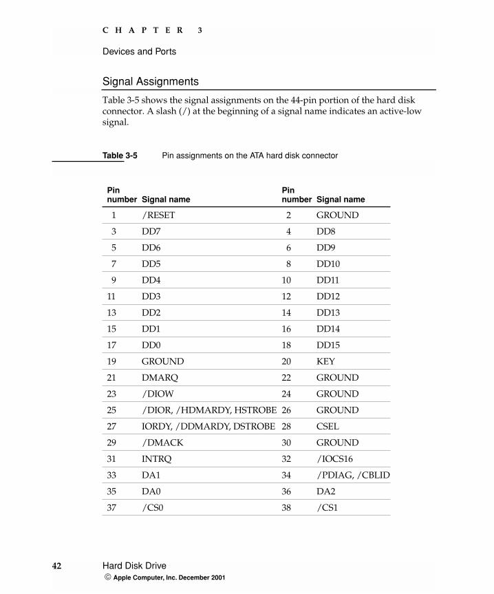
Signal Assignments
Table 3-5 shows the signal assignments on the 44-pin portion of the hard disk connector. A slash (/) at the beginning of a signal name indicates an active-low signal.
Table 3-5 Pin assignments on the ATA hard disk connector
Pin number Signal name
Pin number Signal name
1 /RESET 2 GROUND
3 DD7 4 DD8
5 DD6 6 DD9
7 DD5 8 DD10
9 DD4 10 DD11
11 DD3 12 DD12
13 DD2 14 DD13
15 DD1 16 DD14
17 DD0 18 DD15
19 GROUND 20 KEY
21 DMARQ 22 GROUND
23 /DIOW 24 GROUND
25 /DIOR, /HDMARDY, HSTROBE 26 GROUND
27 IORDY, /DDMARDY, DSTROBE 28 CSEL
29 /DMACK 30 GROUND
31 INTRQ 32 /IOCS16
33 DA1 34 /PDIAG, /CBLID
35 DA0 36 DA2
37 /CS0 38 /CS1
42 Hard Disk Drive Apple Computer, Inc. December 2001
C H A P T E R 3
Devices and Ports
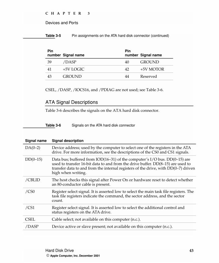
CSEL, /DASP, /IOCS16, and /PDIAG are not used; see Table 3-6.
ATA Signal Descriptions
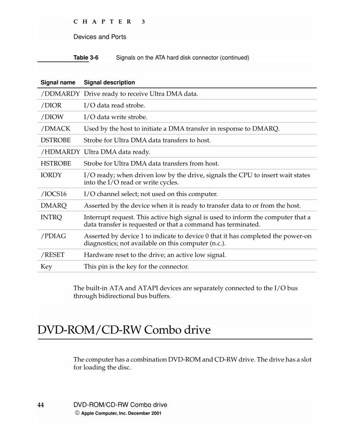
Table 3-6 describes the signals on the ATA hard disk connector.
39 /DASP 40 GROUND
41 +5V LOGIC 42 +5V MOTOR
43 GROUND 44 Reserved
Table 3-6 Signals on the ATA hard disk connector
Signal name Signal description
DA(0–2) Device address; used by the computer to select one of the registers in the ATA drive. For more information, see the descriptions of the CS0 and CS1 signals.
DD(0–15) Data bus; buffered from IOD(16–31) of the computer’s I/O bus. DD(0–15) are used to transfer 16-bit data to and from the drive buffer. DD(8–15) are used to transfer data to and from the internal registers of the drive, with DD(0–7) driven high when writing.
/CBLID The host checks this signal after Power On or hardware reset to detect whether an 80-conductor cable is present.
/CS0 Register select signal. It is asserted low to select the main task file registers. The task file registers indicate the command, the sector address, and the sector count.
/CS1 Register select signal. It is asserted low to select the additional control and status registers on the ATA drive.
CSEL Cable select; not available on this computer (n.c.).
/DASP Device active or slave present; not available on this computer (n.c.).
Table 3-5 Pin assignments on the ATA hard disk connector (continued)
Pin number Signal name
Pin number Signal name
Hard Disk Drive 43 Apple Computer, Inc. December 2001
C H A P T E R 3
Devices and Ports
The built-in ATA and ATAPI devices are separately connected to the I/O bus through bidirectional bus buffers.
DVD-ROM/CD-RW Combo drive
The computer has a combination DVD-ROM and CD-RW drive. The drive has a slot for loading the disc.
/DDMARDY Drive ready to receive Ultra DMA data.
/DIOR I/O data read strobe.
/DIOW I/O data write strobe.
/DMACK Used by the host to initiate a DMA transfer in response to DMARQ.
DSTROBE Strobe for Ultra DMA data transfers to host.
/HDMARDY Ultra DMA data ready.
HSTROBE Strobe for Ultra DMA data transfers from host.
IORDY I/O ready; when driven low by the drive, signals the CPU to insert wait states into the I/O read or write cycles.
/IOCS16 I/O channel select; not used on this computer.
DMARQ Asserted by the device when it is ready to transfer data to or from the host.
INTRQ Interrupt request. This active high signal is used to inform the computer that a data transfer is requested or that a command has terminated.
/PDIAG Asserted by device 1 to indicate to device 0 that it has completed the power-on diagnostics; not available on this computer (n.c.).
/RESET Hardware reset to the drive; an active low signal.
Key This pin is the key for the connector.
Table 3-6 Signals on the ATA hard disk connector (continued)
Signal name Signal description
44 DVD-ROM/CD-RW Combo drive Apple Computer, Inc. December 2001
C H A P T E R 3
Devices and Ports
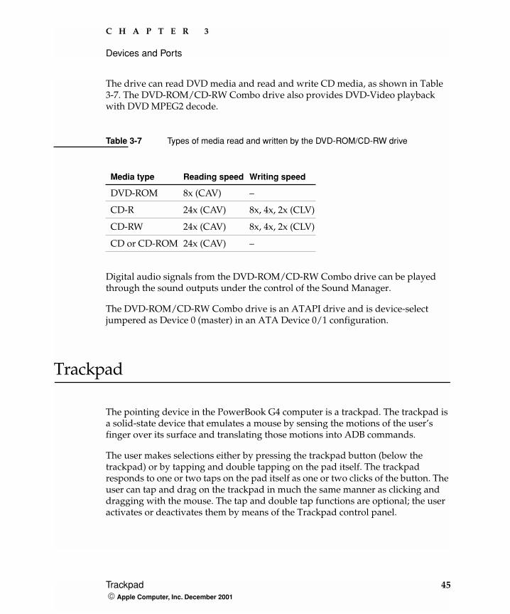
The drive can read DVD media and read and write CD media, as shown in Table 3-7. The DVD-ROM/CD-RW Combo drive also provides DVD-Video playback with DVD MPEG2 decode.
Digital audio signals from the DVD-ROM/CD-RW Combo drive can be played through the sound outputs under the control of the Sound Manager.
The DVD-ROM/CD-RW Combo drive is an ATAPI drive and is device-select jumpered as Device 0 (master) in an ATA Device 0/1 configuration.
Trackpad
The pointing device in the PowerBook G4 computer is a trackpad. The trackpad is a solid-state device that emulates a mouse by sensing the motions of the user’s finger over its surface and translating those motions into ADB commands.
The user makes selections either by pressing the trackpad button (below the trackpad) or by tapping and double tapping on the pad itself. The trackpad responds to one or two taps on the pad itself as one or two clicks of the button. The user can tap and drag on the trackpad in much the same manner as clicking and dragging with the mouse. The tap and double tap functions are optional; the user activates or deactivates them by means of the Trackpad control panel.
Table 3-7 Types of media read and written by the DVD-ROM/CD-RW drive
Media type Reading speed Writing speed
DVD-ROM 8x (CAV) –
CD-R 24x (CAV) 8x, 4x, 2x (CLV)
CD-RW 24x (CAV) 8x, 4x, 2x (CLV)
CD or CD-ROM 24x (CAV) –
Trackpad 45 Apple Computer, Inc. December 2001
C H A P T E R 3
Devices and Ports
Keyboard
The keyboard is a compact, low-profile design with a row of function keys and inverted-T cursor motion keys.
Removing the KeyboardThe keyboard is removable to allow access to the internal components and expansion connectors inside the computer. The keyboard is held in place by a locking screw and two latches.
To unlock the keyboard, the user turns a slotted screw that is part of the Num Lock LED, which is between the F5 and F6 function keys. Turning the screw 180° locks or unlocks the keyboard.
The two latches are between the ESC key and the F1 key and between the F11 and F12 keys. The user can release the latches by pulling them toward the front of the computer.
Changing the Operation of the KeyboardSeveral of the keys on the keyboard have more than one mode of operation.
� Function keys F1–F6 can also control the display brightness, speaker volume, and the Num Lock function; function key F12 is also the media eject key.
� The function keys from F7 through F11 can be set by the user to open applications, documents, or AppleScripts.
� Certain control keys can be used as page-control keys.
� The keys on the right side of the keyboard can be used as a numeric keypad.
Note: The PowerBook G4 computer leaves the factory with keyboard locking screw in the unlocked position.
46 Keyboard Apple Computer, Inc. December 2001
C H A P T E R 3
Devices and Ports
The next sections describe these groups of keys and the way their alternate modes of operation are selected by using the Fn key, the Num Lock key, and the Function Keys checkbox in the Keyboard control panel.
Keyboard Illustrations
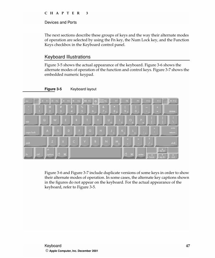
Figure 3-5 shows the actual appearance of the keyboard. Figure 3-6 shows the alternate modes of operation of the function and control keys. Figure 3-7 shows the embedded numeric keypad.
Figure 3-5 Keyboard layout
Figure 3-6 and Figure 3-7 include duplicate versions of some keys in order to show their alternate modes of operation. In some cases, the alternate key captions shown in the figures do not appear on the keyboard. For the actual appearance of the keyboard, refer to Figure 3-5.
?
Keyboard 47 Apple Computer, Inc. December 2001
C H A P T E R 3
Devices and Ports
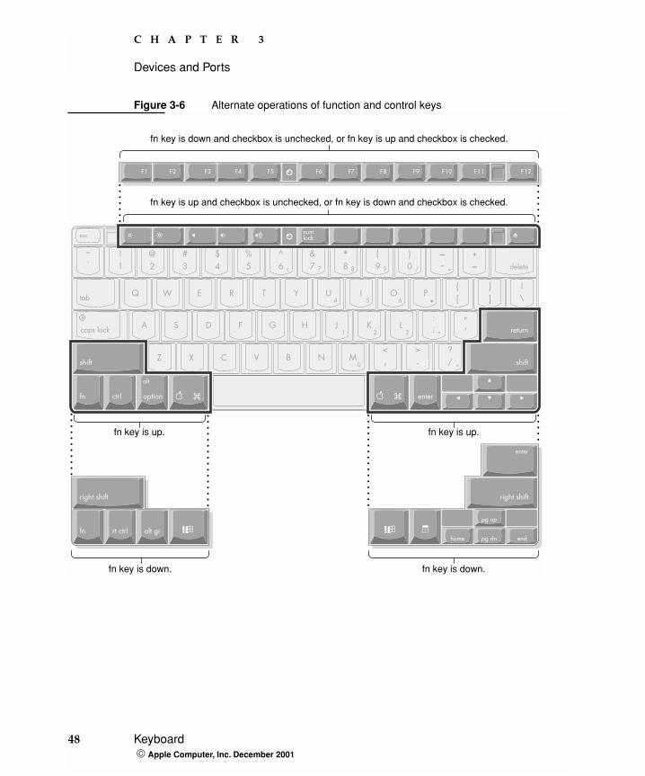
Figure 3-6 Alternate operations of function and control keys
fn key is up and checkbox is unchecked, or fn key is down and checkbox is checked.
fn key is down and checkbox is unchecked, or fn key is up and checkbox is checked.
fn key is up.
fn key is down.
fn key is up.
fn key is down.
48 Keyboard Apple Computer, Inc. December 2001
C H A P T E R 3
Devices and Ports
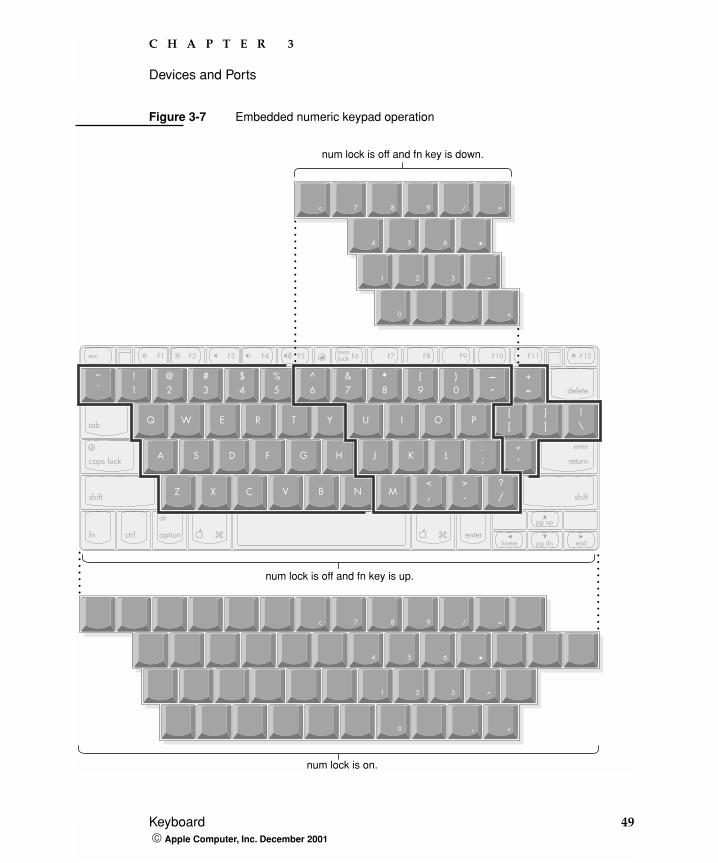
Figure 3-7 Embedded numeric keypad operation
?
num lock is off and fn key is down.
num lock is off and fn key is up.
num lock is on.
Keyboard 49 Apple Computer, Inc. December 2001
C H A P T E R 3
Devices and Ports
Using the Fn Key
Pressing the Fn key affects three sets of keys: the function keys F1–F12, the embedded numeric keypad, and certain modifier keys.
� It toggles the function keys between their control-button operation and their F1–F12 functions, as shown in Table 3-8 and Figure 3-6. The user selects the default modes of operation of those keys as described in the section “The Function-Keys Checkbox” (page 50).
� It selects the embedded numeric keypad on the right portion of the alphanumeric keys, as shown in Table 3-10 and Figure 3-7.
� It changes certain control keys, including the cursor control keys, to page control keys, as shown in Table 3-11 and Figure 3-7.
Using the Num Lock Key
Pressing the Num Lock key affects two sets of keys: the embedded keypad and the rest of the alphanumeric keys.
� It selects the embedded numeric keypad, as shown in Table 3-10 and Figure 3-7.
� It makes the rest of the alphanumeric keys functionless (NOPs), as shown in Figure 3-7.
The Function-Keys Checkbox
The Fn key lets the user switch the mode of operation of the function keys at any time. The user selects the default mode of the function keys by means of the Function-keys checkbox in the Keyboard Control Panel.
The Function-keys checkbox lets the user choose whether the function key operations are primary or secondary. “Function keys primary” means the function keys are normally in their F1–F12 mode of operation and pressing the Fn key selects their control-button mode. “Function keys secondary” means the function keys are normally in their control-button mode and pressing the Fn key selects their function-key mode.
50 Keyboard Apple Computer, Inc. December 2001
C H A P T E R 3
Devices and Ports
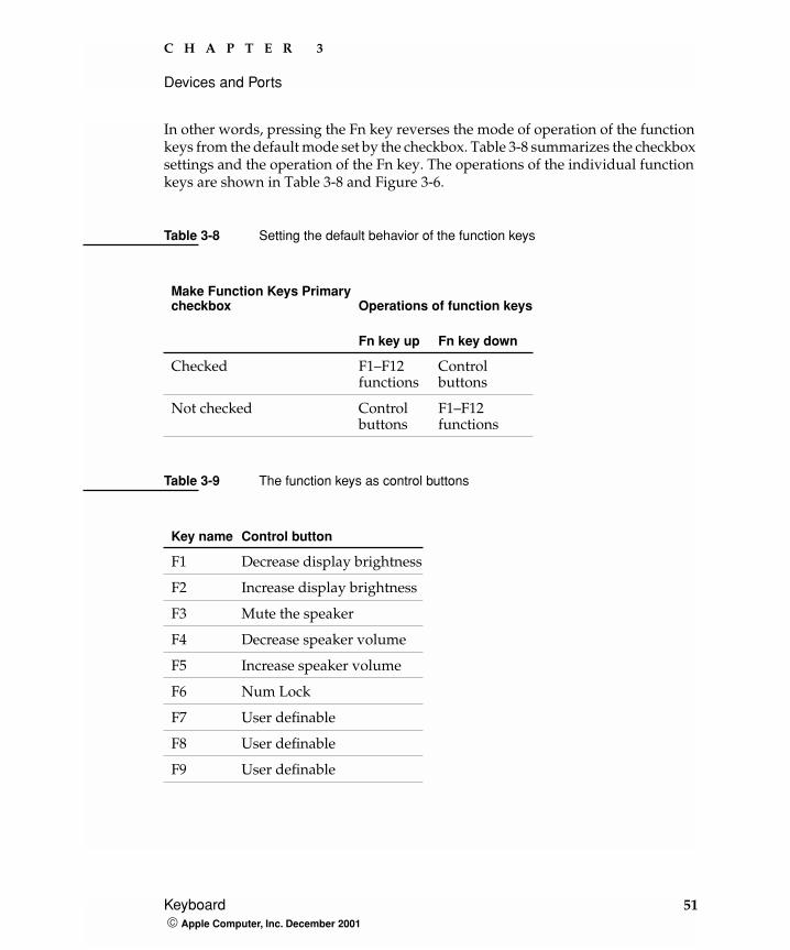
In other words, pressing the Fn key reverses the mode of operation of the function keys from the default mode set by the checkbox. Table 3-8 summarizes the checkbox settings and the operation of the Fn key. The operations of the individual function keys are shown in Table 3-8 and Figure 3-6.
Table 3-8 Setting the default behavior of the function keys
Make Function Keys Primarycheckbox Operations of function keys
Fn key up Fn key down
Checked F1–F12functions
Controlbuttons
Not checked Control buttons
F1–F12functions
Table 3-9 The function keys as control buttons
Key name Control button
F1 Decrease display brightness
F2 Increase display brightness
F3 Mute the speaker
F4 Decrease speaker volume
F5 Increase speaker volume
F6 Num Lock
F7 User definable
F8 User definable
F9 User definable
Keyboard 51 Apple Computer, Inc. December 2001
C H A P T E R 3
Devices and Ports
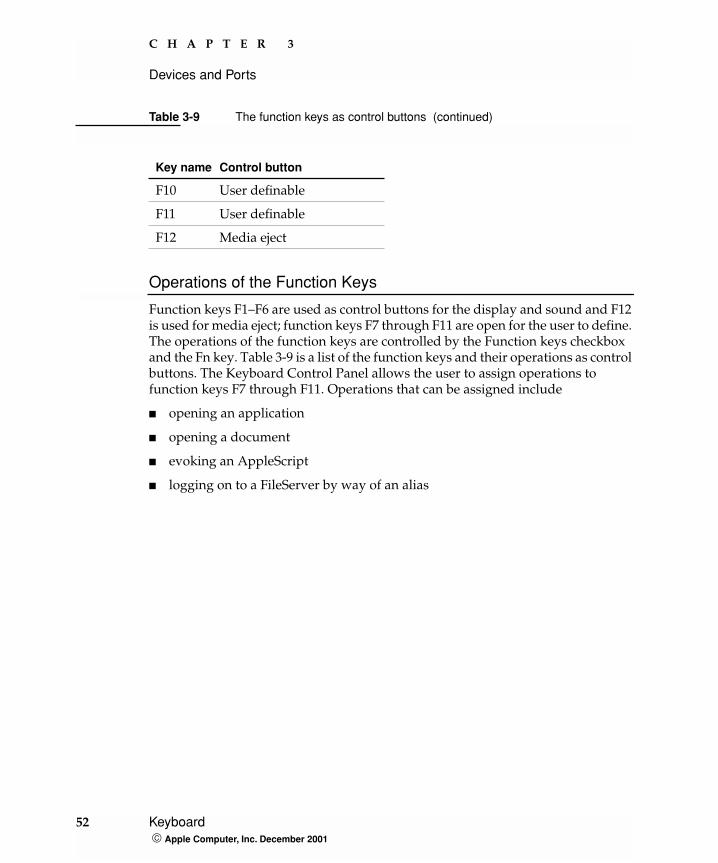
Operations of the Function Keys
Function keys F1–F6 are used as control buttons for the display and sound and F12 is used for media eject; function keys F7 through F11 are open for the user to define. The operations of the function keys are controlled by the Function keys checkbox and the Fn key. Table 3-9 is a list of the function keys and their operations as control buttons. The Keyboard Control Panel allows the user to assign operations to function keys F7 through F11. Operations that can be assigned include
� opening an application
� opening a document
� evoking an AppleScript
� logging on to a FileServer by way of an alias
F10 User definable
F11 User definable
F12 Media eject
Table 3-9 The function keys as control buttons (continued)
Key name Control button
52 Keyboard Apple Computer, Inc. December 2001
C H A P T E R 3
Devices and Ports
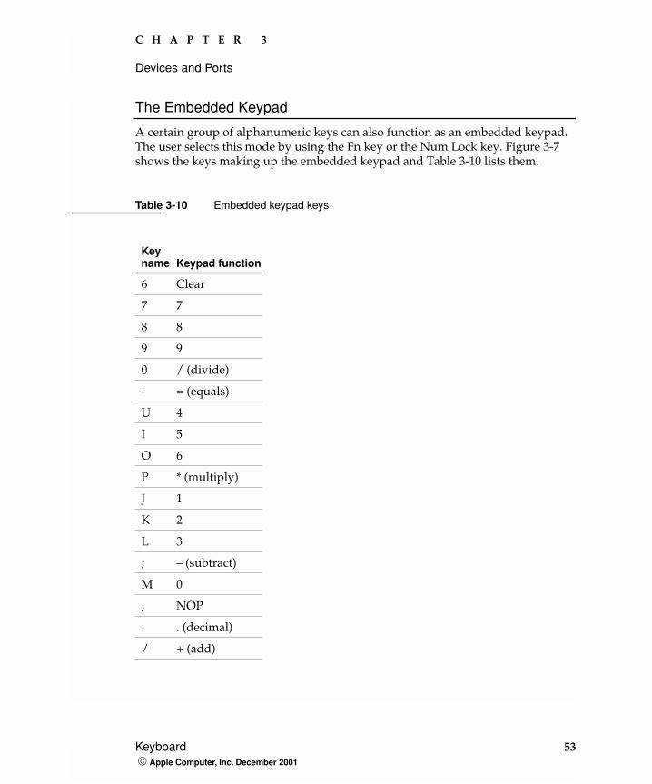
The Embedded Keypad
A certain group of alphanumeric keys can also function as an embedded keypad. The user selects this mode by using the Fn key or the Num Lock key. Figure 3-7 shows the keys making up the embedded keypad and Table 3-10 lists them.
Table 3-10 Embedded keypad keys
Key name Keypad function
6 Clear
7 7
8 8
9 9
0 / (divide)
- = (equals)
U 4
I 5
O 6
P * (multiply)
J 1
K 2
L 3
; – (subtract)
M 0
, NOP
. . (decimal)
/ + (add)
Keyboard 53 Apple Computer, Inc. December 2001
C H A P T E R 3
Devices and Ports
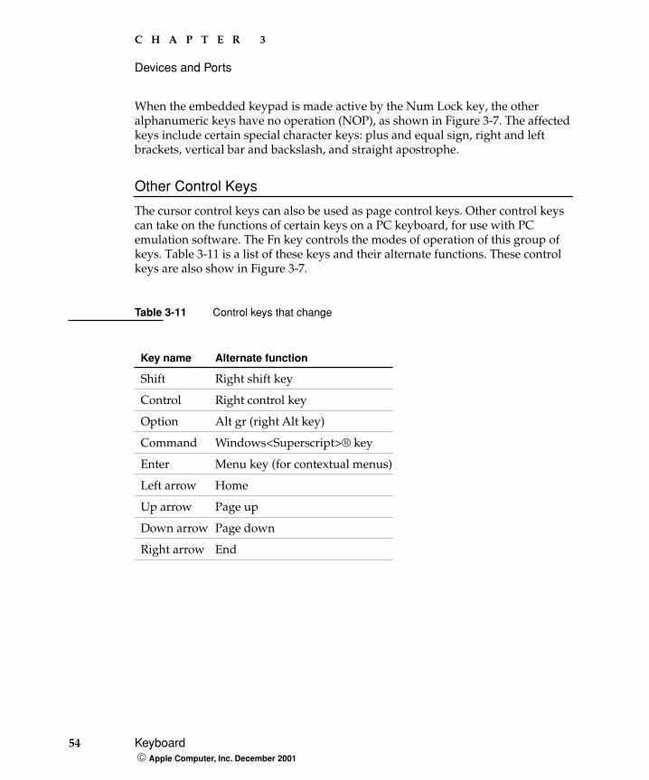
When the embedded keypad is made active by the Num Lock key, the other alphanumeric keys have no operation (NOP), as shown in Figure 3-7. The affected keys include certain special character keys: plus and equal sign, right and left brackets, vertical bar and backslash, and straight apostrophe.
Other Control Keys
The cursor control keys can also be used as page control keys. Other control keys can take on the functions of certain keys on a PC keyboard, for use with PC emulation software. The Fn key controls the modes of operation of this group of keys. Table 3-11 is a list of these keys and their alternate functions. These control keys are also show in Figure 3-7.
Table 3-11 Control keys that change
Key name Alternate function
Shift Right shift key
Control Right control key
Option Alt gr (right Alt key)
Command Windows<Superscript>® key
Enter Menu key (for contextual menus)
Left arrow Home
Up arrow Page up
Down arrow Page down
Right arrow End
54 Keyboard Apple Computer, Inc. December 2001
C H A P T E R 3
Devices and Ports
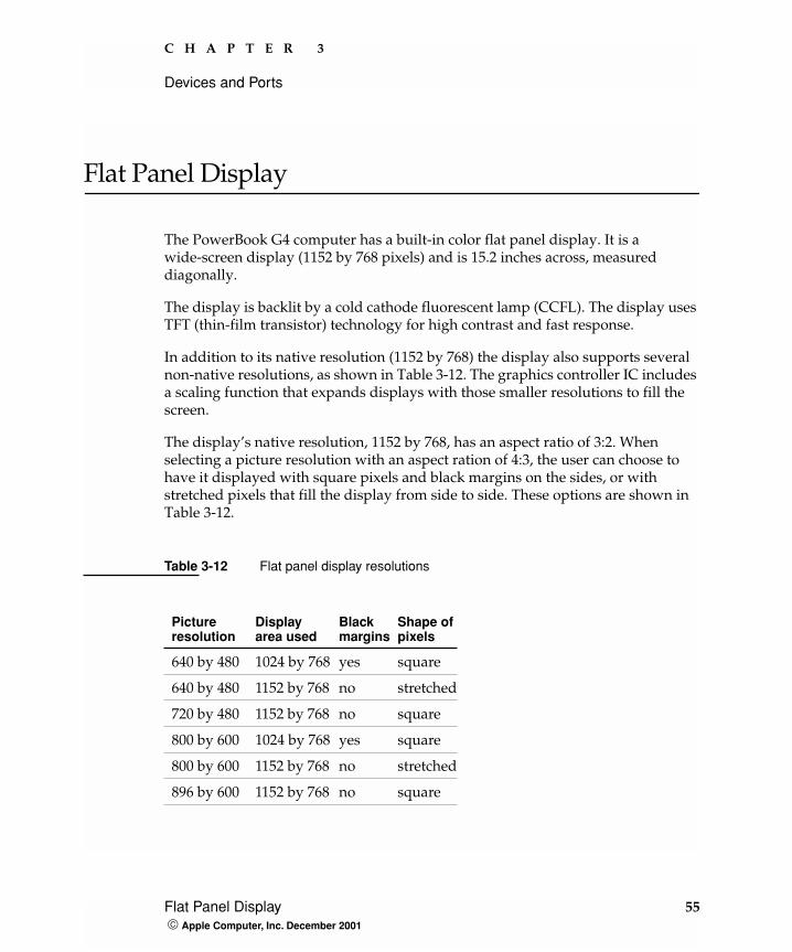
Flat Panel Display
The PowerBook G4 computer has a built-in color flat panel display. It is a wide-screen display (1152 by 768 pixels) and is 15.2 inches across, measured diagonally.
The display is backlit by a cold cathode fluorescent lamp (CCFL). The display uses TFT (thin-film transistor) technology for high contrast and fast response.
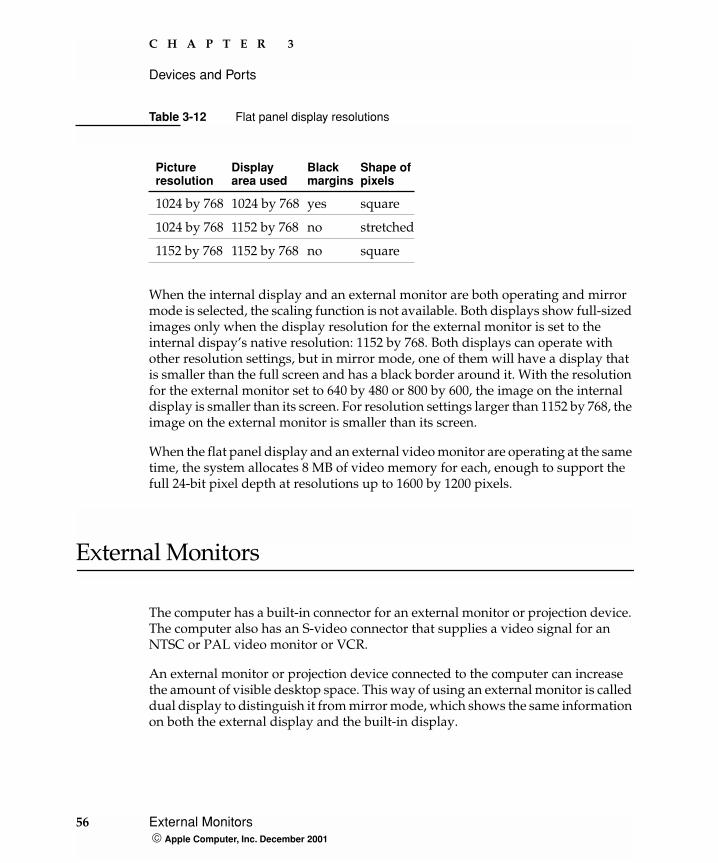
In addition to its native resolution (1152 by 768) the display also supports several non-native resolutions, as shown in Table 3-12. The graphics controller IC includes a scaling function that expands displays with those smaller resolutions to fill the screen.
The display’s native resolution, 1152 by 768, has an aspect ratio of 3:2. When selecting a picture resolution with an aspect ration of 4:3, the user can choose to have it displayed with square pixels and black margins on the sides, or with stretched pixels that fill the display from side to side. These options are shown in Table 3-12.
Table 3-12 Flat panel display resolutions
Pictureresolution
Displayarea used
Blackmargins
Shape ofpixels
640 by 480 1024 by 768 yes square
640 by 480 1152 by 768 no stretched
720 by 480 1152 by 768 no square
800 by 600 1024 by 768 yes square
800 by 600 1152 by 768 no stretched
896 by 600 1152 by 768 no square
Flat Panel Display 55 Apple Computer, Inc. December 2001
C H A P T E R 3
Devices and Ports
When the internal display and an external monitor are both operating and mirror mode is selected, the scaling function is not available. Both displays show full-sized images only when the display resolution for the external monitor is set to the internal dispay’s native resolution: 1152 by 768. Both displays can operate with other resolution settings, but in mirror mode, one of them will have a display that is smaller than the full screen and has a black border around it. With the resolution for the external monitor set to 640 by 480 or 800 by 600, the image on the internal display is smaller than its screen. For resolution settings larger than 1152 by 768, the image on the external monitor is smaller than its screen.
When the flat panel display and an external video monitor are operating at the same time, the system allocates 8 MB of video memory for each, enough to support the full 24-bit pixel depth at resolutions up to 1600 by 1200 pixels.
External Monitors
The computer has a built-in connector for an external monitor or projection device. The computer also has an S-video connector that supplies a video signal for an NTSC or PAL video monitor or VCR.
An external monitor or projection device connected to the computer can increase the amount of visible desktop space. This way of using an external monitor is called dual display to distinguish it from mirror mode, which shows the same information on both the external display and the built-in display.
1024 by 768 1024 by 768 yes square
1024 by 768 1152 by 768 no stretched
1152 by 768 1152 by 768 no square
Table 3-12 Flat panel display resolutions
Pictureresolution
Displayarea used
Blackmargins
Shape ofpixels
56 External Monitors Apple Computer, Inc. December 2001
C H A P T E R 3
Devices and Ports
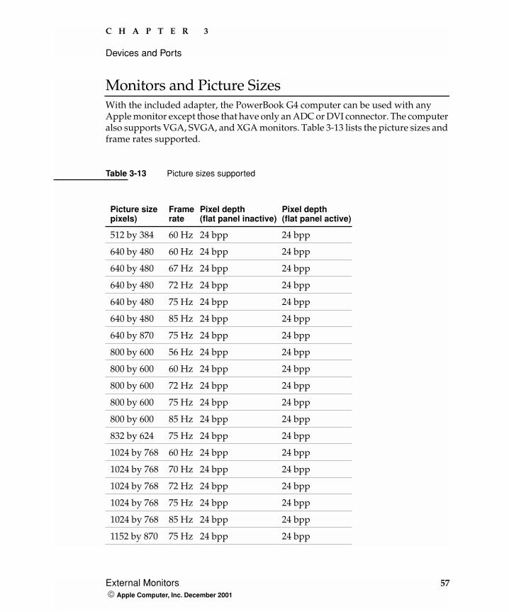
Monitors and Picture SizesWith the included adapter, the PowerBook G4 computer can be used with any Apple monitor except those that have only an ADC or DVI connector. The computer also supports VGA, SVGA, and XGA monitors. Table 3-13 lists the picture sizes and frame rates supported.
Table 3-13 Picture sizes supported
Picture sizepixels)
Framerate
Pixel depth (flat panel inactive)
Pixel depth (flat panel active)
512 by 384 60 Hz 24 bpp 24 bpp
640 by 480 60 Hz 24 bpp 24 bpp
640 by 480 67 Hz 24 bpp 24 bpp
640 by 480 72 Hz 24 bpp 24 bpp
640 by 480 75 Hz 24 bpp 24 bpp
640 by 480 85 Hz 24 bpp 24 bpp
640 by 870 75 Hz 24 bpp 24 bpp
800 by 600 56 Hz 24 bpp 24 bpp
800 by 600 60 Hz 24 bpp 24 bpp
800 by 600 72 Hz 24 bpp 24 bpp
800 by 600 75 Hz 24 bpp 24 bpp
800 by 600 85 Hz 24 bpp 24 bpp
832 by 624 75 Hz 24 bpp 24 bpp
1024 by 768 60 Hz 24 bpp 24 bpp
1024 by 768 70 Hz 24 bpp 24 bpp
1024 by 768 72 Hz 24 bpp 24 bpp
1024 by 768 75 Hz 24 bpp 24 bpp
1024 by 768 85 Hz 24 bpp 24 bpp
1152 by 870 75 Hz 24 bpp 24 bpp
External Monitors 57 Apple Computer, Inc. December 2001
C H A P T E R 3
Devices and Ports
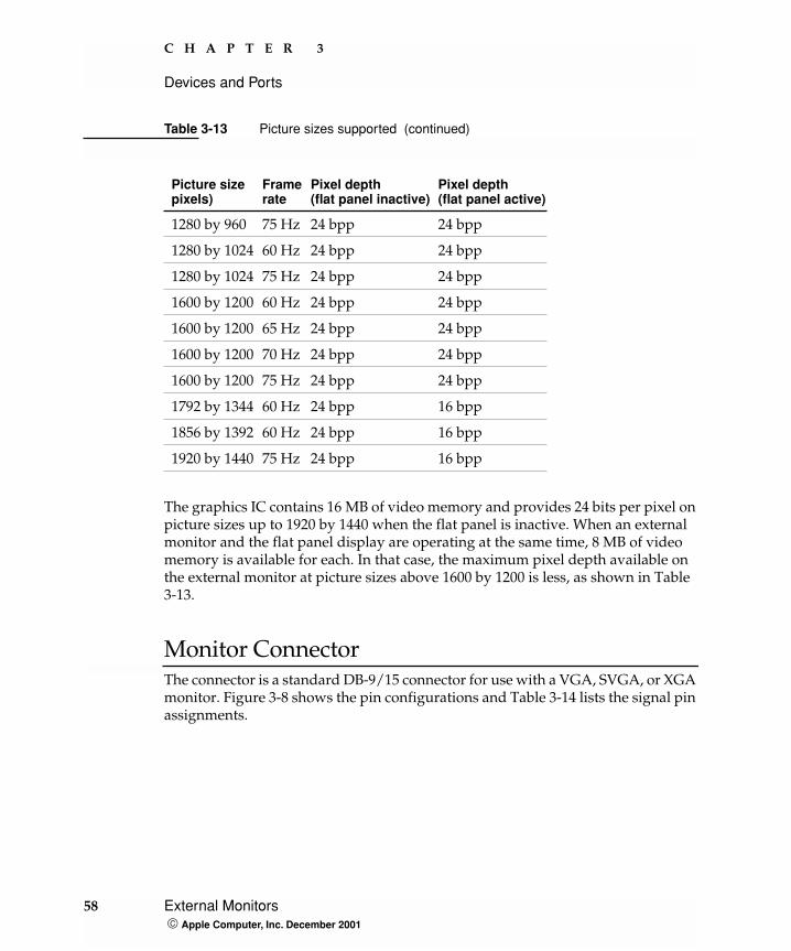
The graphics IC contains 16 MB of video memory and provides 24 bits per pixel on picture sizes up to 1920 by 1440 when the flat panel is inactive. When an external monitor and the flat panel display are operating at the same time, 8 MB of video memory is available for each. In that case, the maximum pixel depth available on the external monitor at picture sizes above 1600 by 1200 is less, as shown in Table 3-13.
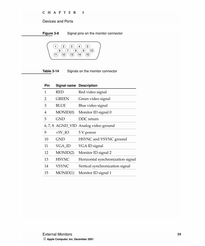
Monitor ConnectorThe connector is a standard DB-9/15 connector for use with a VGA, SVGA, or XGA monitor. Figure 3-8 shows the pin configurations and Table 3-14 lists the signal pin assignments.
1280 by 960 75 Hz 24 bpp 24 bpp
1280 by 1024 60 Hz 24 bpp 24 bpp
1280 by 1024 75 Hz 24 bpp 24 bpp
1600 by 1200 60 Hz 24 bpp 24 bpp
1600 by 1200 65 Hz 24 bpp 24 bpp
1600 by 1200 70 Hz 24 bpp 24 bpp
1600 by 1200 75 Hz 24 bpp 24 bpp
1792 by 1344 60 Hz 24 bpp 16 bpp
1856 by 1392 60 Hz 24 bpp 16 bpp
1920 by 1440 75 Hz 24 bpp 16 bpp
Table 3-13 Picture sizes supported (continued)
Picture sizepixels)
Framerate
Pixel depth (flat panel inactive)
Pixel depth (flat panel active)
58 External Monitors Apple Computer, Inc. December 2001
C H A P T E R 3
Devices and Ports
Figure 3-8 Signal pins on the monitor connector
Table 3-14 Signals on the monitor connector
Pin Signal name Description
1 RED Red video signal
2 GREEN Green video signal
3 BLUE Blue video signal
4 MONID(0) Monitor ID signal 0
5 GND DDC return
6, 7, 8 AGND_VID Analog video ground
9 +5V_IO 5 V power
10 GND HSYNC and VSYNC ground
11 VGA_ID VGA ID signal
12 MONID(2) Monitor ID signal 2
13 HSYNC Horizontal synchronization signal
14 VSYNC Vertical synchronization signal
15 MONID(1) Monitor ID signal 1
1 2 3 4 56 7 8 9 10
11 12 13 14 15
External Monitors 59 Apple Computer, Inc. December 2001
C H A P T E R 3
Devices and Ports
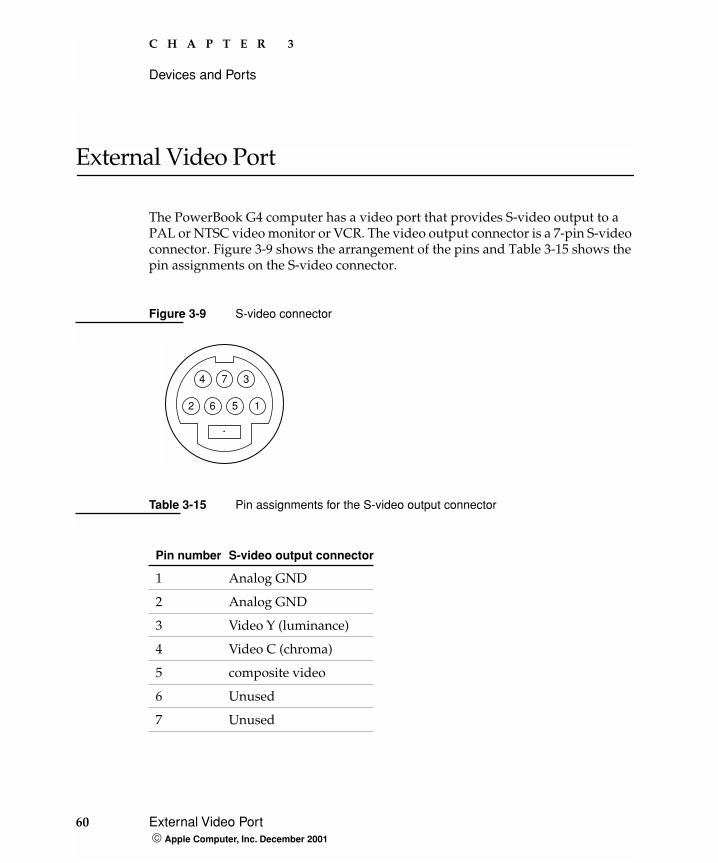
External Video Port
The PowerBook G4 computer has a video port that provides S-video output to a PAL or NTSC video monitor or VCR. The video output connector is a 7-pin S-video connector. Figure 3-9 shows the arrangement of the pins and Table 3-15 shows the pin assignments on the S-video connector.
Figure 3-9 S-video connector
Table 3-15 Pin assignments for the S-video output connector
Pin number S-video output connector
1 Analog GND
2 Analog GND
3 Video Y (luminance)
4 Video C (chroma)
5 composite video
6 Unused
7 Unused
1
4 7
2 6 5
3
60 External Video Port Apple Computer, Inc. December 2001
C H A P T E R 3
Devices and Ports
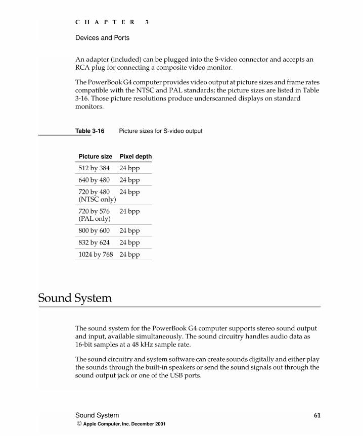
An adapter (included) can be plugged into the S-video connector and accepts an RCA plug for connecting a composite video monitor.
The PowerBook G4 computer provides video output at picture sizes and frame rates compatible with the NTSC and PAL standards; the picture sizes are listed in Table 3-16. Those picture resolutions produce underscanned displays on standard monitors.
Sound System
The sound system for the PowerBook G4 computer supports stereo sound output and input, available simultaneously. The sound circuitry handles audio data as 16-bit samples at a 48 kHz sample rate.
The sound circuitry and system software can create sounds digitally and either play the sounds through the built-in speakers or send the sound signals out through the sound output jack or one of the USB ports.
Table 3-16 Picture sizes for S-video output
Picture size Pixel depth
512 by 384 24 bpp
640 by 480 24 bpp
720 by 480(NTSC only)
24 bpp
720 by 576(PAL only)
24 bpp
800 by 600 24 bpp
832 by 624 24 bpp
1024 by 768 24 bpp
Sound System 61 Apple Computer, Inc. December 2001
C H A P T E R 3
Devices and Ports
The PowerBook G4 computer can record sound data from either the built-in microphone, an audio CD, a USB audio device, or a CardBus card. For each sound input source, sound playthrough can be enabled or disabled. Sound data from digital sources is converted to analog form for output to the speakers and the sound output jack.
Sound InputsThe sound system accepts inputs from four possible sources:
� the built-in microphone
� a CD or DVD in the DVD-ROM/CD-RW Combo drive
� a digital audio device connected to a USB or FireWire port
� sound signals from the communication (modem) slot
The microphone preamp has a dedicated analog input channel in the Tumbler ciruitry; the other inputs send digital data. The analog input can be set for play-through or recording. The digital inputs can be selected or mixed by the Tumbler sound circuitry.
The computer also accepts digital sound data from the DVD-ROM/CD-RW Combo drive or from devices connected to the USB or FireWire ports. Sound data from those sources can be sent to the sound system to be converted to analog form for output to the speakers and the output jack.
Built-in Microphone
The sound signal from the built-in microphone goes through a dedicated preamplifier that raises its nominal 30-mV level to a nominal 150 mV (peak-to-peak) signal to the sound circuitry. That signal level assures good quality digitizing without driving the analog input into clipping.
Modem Activity Sound Signals
Modem activity sound signals from the communications slot are sent to the Tumbler sound circuitry as 8-bit digital data.
Note: The PowerBook G4 computer does not have a sound input jack. The USB port can be used for sound input from a USB microphone.
62 Sound System Apple Computer, Inc. December 2001
C H A P T E R 3
Devices and Ports
Sound OutputsThe sound system sends sound output signals to the built-in speakers and the external sound output jack.
Headphone Jack
The headphone jack is located on the left side of the computer. The headphone jack provides enough current to drive a pair of low-impedance headphones. It can also be used as a line-level output.
The headphone jack has the following electrical characteristics:
� impedance suitable for driving standard 32-ohm headphones
� output level 2.0 V peak-to-peak (0.7 V RMS)
� signal-to-noise (SNR) 90 dB unweighted (typical)
� total harmonic distortion (THD) 0.03% or less
Internal Speakers
The computer has two 20mm speakers, one on either side of the keyboard. The computer turns off the sound signals to the speakers when an external device is connected to the sound output jack and during power cycling.
Digitizing SoundThe sound circuitry digitizes and records sound as 48-kHz 16-bit samples. If a sound sampled at a lower rate on another computer is played as output, the Sound Manager transparently upsamples the sound to 48 kHz prior to outputting the audio to the sound circuitry.
When recording sound from a microphone, applications that may be affected by feedback should disable sound playthrough by calling the Sound Manager APIs.
Sound System 63 Apple Computer, Inc. December 2001

C H A P T E R 3
Devices and Ports
64 Sound System Apple Computer, Inc. December 2001
C H A P T E R 4
4 Expansion Features
This chapter describes the expansion features of the PowerBook G4 computer: the RAM expansion slots and the CardBus slot.
RAM Expansion Slots
The computer has two RAM expansion slots that accommodate standard SO (small outline) DIMMs using SDRAM devices. One or both of the slots may be occupied by a factory-installed SO-DIMM. The slots are accessible for user installation of an additional or larger SO-DIMM.
RAM expansion SO-DIMMs for both models must be PC133 compliant. PC133 SO-DIMMs in the 550-MHz model operate at the speed of PC100 modules.
The SO-DIMMs must use SDRAM devices. If the user installs an SO-DIMM that uses EDO devices, the boot process will fail when the user attempts to restart the computer and the computer will not operate.
The address logic for the RAM slots supports up to 1 GB total RAM. Using the highest-density devices currently available, an SO-DIMM can contain up to 512 MB of RAM, so the two RAM expansion slots can accomodate up to 1 GB total RAM.
Note: Some configurations come with factory-installed SO-DIMMs in both slots.
RAM Expansion Slots 65 Apple Computer, Inc. December 2001
C H A P T E R 4
Expansion Features
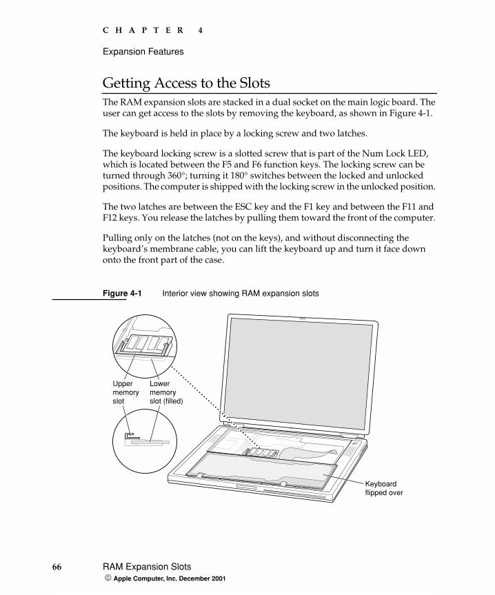
Getting Access to the SlotsThe RAM expansion slots are stacked in a dual socket on the main logic board. The user can get access to the slots by removing the keyboard, as shown in Figure 4-1.
The keyboard is held in place by a locking screw and two latches.
The keyboard locking screw is a slotted screw that is part of the Num Lock LED, which is located between the F5 and F6 function keys. The locking screw can be turned through 360°; turning it 180° switches between the locked and unlocked positions. The computer is shipped with the locking screw in the unlocked position.
The two latches are between the ESC key and the F1 key and between the F11 and F12 keys. You release the latches by pulling them toward the front of the computer.
Pulling only on the latches (not on the keys), and without disconnecting the keyboard’s membrane cable, you can lift the keyboard up and turn it face down onto the front part of the case.
Figure 4-1 Interior view showing RAM expansion slots
Uppermemoryslot
Lowermemoryslot (filled)
Keyboardflipped over
66 RAM Expansion Slots Apple Computer, Inc. December 2001
C H A P T E R 4
Expansion Features
Mechanical Design of RAM SO-DIMMsThe RAM expansion modules used in the PowerBook G4 computer are standard 144-pin 8-byte DRAM SO-DIMMs, as defined in the JEDEC specifications.
The mechanical characteristics of the RAM expansion SO-DIMM are given in the JEDEC specification for the 144-pin 8-byte DRAM SO-DIMM. The specification number is JEDEC MO-190-C. To obtain a copy of the specification, see the references listed at “RAM Expansion Modules” (page 77).
The specification defines SO-DIMMs with nominal heights of 1.0, 1.25, 1.5, and 2.0 inches. The PowerBook G4 computer can accommodate SO-DIMMS with heights of 1.25 inches or less.
ImportantThe PowerBook G4 computer will not accept a 1.5-inch or 2-inch SO-DIMM.
The JEDEC specification defines the maximum depth or thickness of an SO-DIMM as 3.8 mm. That specification is also a maximum: Modules that exceed the specified thickness can cause reliability problems.
Electrical Design of RAM SO-DIMMsSO-DIMMs for the 667-MHz model are required to be PC133 compliant. For information about the PC133 and PC100 specifications, see the references at “RAM Expansion Modules” (page 77).
ImportantPC100 DIMMs will not work in the 667-MHz model.
The electrical characteristics of the RAM SO-DIMM are given in section 4.5.6 of the JEDEC Standard 21-C, release 7. To obtain a copy of the specification, see the references listed at “RAM Expansion Modules” (page 77).
The JEDEC and Intel specifications define several attributes of the DIMM, including storage capacity and configuration, connector pin assignments, and electrical loading. The specifications support SO-DIMMs with either one or two banks of memory.
RAM Expansion Slots 67 Apple Computer, Inc. December 2001
C H A P T E R 4
Expansion Features
ImportantThe memory controller on the PowerBook G4 computer uses a separate CKE signals for each bank, as called out in the JEDEC specification. SO-DIMMs that have all the CKE pins connected together will not operate properly.
The JEDEC specification for the SO-DIMM defines a Serial Presence Detect (SPD) feature that contains the attributes of the module. SO-DIMMs for use in PowerBook computers are required to have the SPD feature. Information about the required values to be stored in the presence detect EEPROM is in section 4.1.2.5 and Figure 4.5.6–C (144 Pin SDRAM SO–DIMM, PD INFORMATION) of the JEDEC standard 21-C specification, release 7.
ImportantFor a DIMM to be recognized by the startup software, the Serial Presence Detect (SPD) feature must be programmed properly to indicate the timing modes supported by the DIMM.
Capacitance of the data lines must be kept to a minimum. Individual DRAM devices should have a pin capacitance of not more than 5 pF on each data pin.
SDRAM Devices
The SDRAM devices used in the RAM expansion modules must be self-refresh type devices for operation from a 3.3-V power supply. The speed of the SDRAM devices must be 100 MHz or higher for the 550-MHz model and 133 MHz or higher for the 667-MHz model.
The devices are programmed to operate with a CAS latency of 3. At that CAS latency, the access time from the clock transition must be 5.4 ns or less. The burst length must be at least 4 and the minimum clock delay for back-to-back random column access cycles must be a latency of 1 clock cycle.
When the computer is in Sleep mode, the RAM modules are in self-refresh mode and the maximum power-supply current available for each RAM module is 8 mA (see the section “RAM SO-DIMM Electrical Limits” (page 70)). Developers should specify SDRAM devices with low power specifications so as to stay within that limit.
68 RAM Expansion Slots Apple Computer, Inc. December 2001
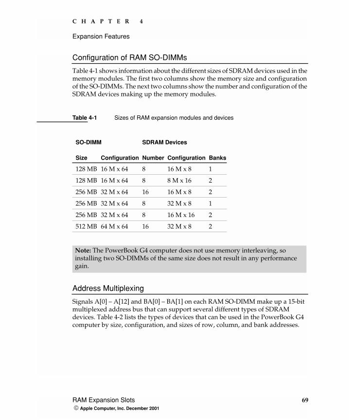
C H A P T E R 4
Expansion Features
Configuration of RAM SO-DIMMs
Table 4-1 shows information about the different sizes of SDRAM devices used in the memory modules. The first two columns show the memory size and configuration of the SO-DIMMs. The next two columns show the number and configuration of the SDRAM devices making up the memory modules.
Address Multiplexing
Signals A[0] – A[12] and BA[0] – BA[1] on each RAM SO-DIMM make up a 15-bit multiplexed address bus that can support several different types of SDRAM devices. Table 4-2 lists the types of devices that can be used in the PowerBook G4 computer by size, configuration, and sizes of row, column, and bank addresses.
Table 4-1 Sizes of RAM expansion modules and devices
SO-DIMM SDRAM Devices
Size Configuration Number Configuration Banks
128 MB 16 M x 64 8 16 M x 8 1
128 MB 16 M x 64 8 8 M x 16 2
256 MB 32 M x 64 16 16 M x 8 2
256 MB 32 M x 64 8 32 M x 8 1
256 MB 32 M x 64 8 16 M x 16 2
512 MB 64 M x 64 16 32 M x 8 2
Note: The PowerBook G4 computer does not use memory interleaving, so installing two SO-DIMMs of the same size does not result in any performance gain.
RAM Expansion Slots 69 Apple Computer, Inc. December 2001
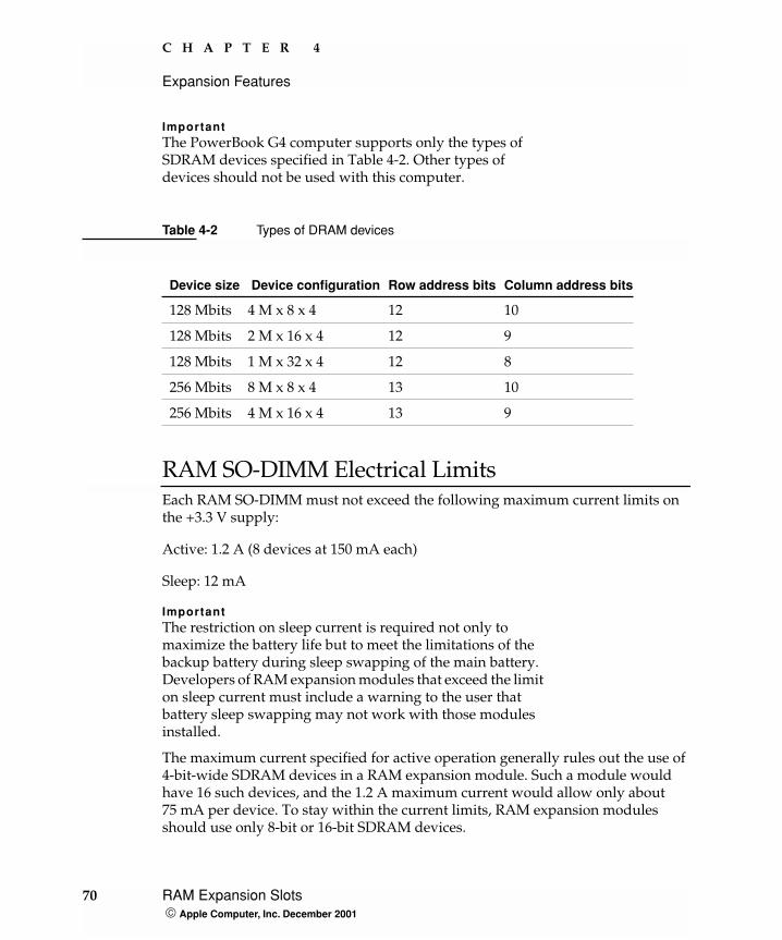
C H A P T E R 4
Expansion Features
ImportantThe PowerBook G4 computer supports only the types of SDRAM devices specified in Table 4-2. Other types of devices should not be used with this computer.
RAM SO-DIMM Electrical LimitsEach RAM SO-DIMM must not exceed the following maximum current limits on the +3.3 V supply:
Active: 1.2 A (8 devices at 150 mA each)
Sleep: 12 mA
ImportantThe restriction on sleep current is required not only to maximize the battery life but to meet the limitations of the backup battery during sleep swapping of the main battery. Developers of RAM expansion modules that exceed the limit on sleep current must include a warning to the user that battery sleep swapping may not work with those modules installed.
The maximum current specified for active operation generally rules out the use of 4-bit-wide SDRAM devices in a RAM expansion module. Such a module would have 16 such devices, and the 1.2 A maximum current would allow only about 75 mA per device. To stay within the current limits, RAM expansion modules should use only 8-bit or 16-bit SDRAM devices.
Table 4-2 Types of DRAM devices
Device size Device configuration Row address bits Column address bits
128 Mbits 4 M x 8 x 4 12 10
128 Mbits 2 M x 16 x 4 12 9
128 Mbits 1 M x 32 x 4 12 8
256 Mbits 8 M x 8 x 4 13 10
256 Mbits 4 M x 16 x 4 13 9
70 RAM Expansion Slots Apple Computer, Inc. December 2001

C H A P T E R 4
Expansion Features
CardBus Slot
The CardBus slot accepts one Type I or Type II card. The slot supports both 16-bit PC Cards and 32-bit CardBus Cards. The card can be removed and replaced while the computer is operating.
For information about the CardBus and the PC Card Manager, refer to the CardBus DDK and the PC Card Manager SDK. To obtain the DDK and the SDK, see the reference at “PC Card Manager” (page 77).
ImportantAs noted in the user manual, the AirPort Card does not work in the CardBus slot.
Note: The CardBus slot does not provide 12-V power.
CardBus Slot 71 Apple Computer, Inc. December 2001

C H A P T E R 4
Expansion Features
72 CardBus Slot Apple Computer, Inc. December 2001
A P P E N D I X A
A Supplemental Reference Documents
For more information about the technologies mentioned in this developer note, you may wish to consult some of the following references.
For information about older models of Macintosh computers, refer to the developer notes archive at
http://developer.apple.com/techpubs/hardware/hardware2.html.
You should also have copies of the relevant books describing the system software for Macintosh computers available in technical bookstores and on the World Wide Web at
http://developer.apple.com/techpubs/macos8/mac8.html
Apple Technotes
Apple Technotes answer many specific questions about the operation of Macintosh computers and the Mac OS. The technotes are available on the Technote website at
http://developer.apple.com/technotes/
Apple Technotes 73 Apple Computer, Inc. December 2001
A P P E N D I X A
Supplemental Reference Documents
3D Graphics
Developers of 3D graphics for games should know about OpenGL for Macintosh®, a new version of SGI’s application programming interface (API) and software library for 3D graphics.
Information is available on the World Wide Web at
http://www.apple.com/opengl
Developer support and documentation is available at
http://developer.apple.com/opengl/
PowerPC G4 Microprocessor
Information about the PowerPC G4 microprocessor is available on the World Wide Web at
http://www.mot.com/SPS/RISC/smartnetworks/arch/powerpc/index.htm
Velocity Engine (AltiVec)
Velocity Engine is Apple’s name for the AltiVec vector processor in the PowerPC G4 microprocessor. Apple provides support for developers who are starting to use the Velocity Engine in their applications. Documentation, development tools, and sample code are now available on the World Wide Web, at
http://developer.apple.com/hardware/ve/index.html
74 3D Graphics Apple Computer, Inc. December 2001
A P P E N D I X A
Supplemental Reference Documents
AltiVec Technology Programming Environments Manual (AltiVec PEM) is a reference guide for programmers. It contains a description for each instruction and information to help in understanding how the instruction works. You can obtain a copy of the AltiVec PEM through the Motorola AltiVec site on the World Wide Web, at
http://www.mot.com/SPS/RISC/smartnetworks/arch/powerpc/features/altivec/avindex.htm
Mac OS X
For access to Apple’s developer documentation for Mac OS X, see the website at
http://developer.apple.com/techpubs/macosx/macosx.html
Two introductory books are available: Mac OS X: An Overview for Developers, and Inside Mac OS X: System Overview. Both are available on the Mac OS X website at
http://developer.apple.com/macosx/gettingstarted/
O'Reilly & Associates publishes a series of books about Mac OS X development. The books in this series have been technically reviewed by Apple engineers and are recommended by the Apple Developer Connection. The first Mac OS X titles, Learning Carbon and Learning Cocoa, are avilable now. In addition to the book series, the O'Reilly Network provides news and articles for Macintosh Developers on the World Wide Web at
http://www.oreillynet.com/mac
Mac OS X 75 Apple Computer, Inc. December 2001
A P P E N D I X A
Supplemental Reference Documents
Mac OS 9
For a description of Mac OS 9.2.2, developers should refer to the technote for Mac OS 9.2.2. Other technotes contain information about the New World software architecture and the API changes for Power Manager 2.0. The technotes are available on the Technote website at
http://developer.apple.com/technotes/
Developers should also have copies of the relevant books describing the system software for Macintosh computers available in technical bookstores and on the World Wide Web at
http://developer.apple.com/techpubs/macos8/mac8.html
Open Firmware
Three Technotes provide an introduction to Open Firmware on the Macintosh platform. They are:
TN 1061: Open Firmware, Part I, available on the Technote website at
http://developer.apple.com/technotes/tn/tn1061.html
TN 1062: Open Firmware, Part II, available on the Technote website at
http://developer.apple.com/technotes/tn/tn1062.html
TN 1044: Open Firmware, Part III, available on the Technote website at
http://developer.apple.com/technotes/tn/tn1044.html
76 Mac OS 9 Apple Computer, Inc. December 2001
A P P E N D I X A
Supplemental Reference Documents
Another Technote tells how to debug open firmware code. Please refer to TN 2004: Debugging Open Firmware Using Telnet, available on the Technote web site at
http://developer.apple.com/technotes/tn/tn2004.html
RAM Expansion Modules
The mechanical characteristics of the RAM SO-DIMM are given in JEDEC specification number JEDEC MO190-C. The specification can be found by using the search string MO190-C on the Electronics Industry Association’s website at
http://www.jedec.org/DOWNLOAD/default.cfm
The electrical characteristics of the RAM SO-DIMM are given in JEDEC Standard 21-C. The specification can be found by using the search string JESD21-C on the Electronics Industry Association’s website at
http://www.jedec.org/DOWNLOAD/default.cfm
The RAM DIMMs are required to be PC133 or PC100 compliant. Information about the PC133 and PC100 specifications is available from Intel’s website at
http://developer.intel.com/technology/memory/pcsdram/
PC Card Manager
For information about the CardBus and the PC Card Manager, refer to the CardBus DDK and the PC Card Manager SDK. The DDK and SDK are available on the Apple Developer World web page at
http://developer.apple.com/sdk/index.html
RAM Expansion Modules 77 Apple Computer, Inc. December 2001
A P P E N D I X A
Supplemental Reference Documents
ATA Devices
For information about the system software for ATA devices such as the IDE drive, see Technote #1098, ATA Device Software Guide Additions and Corrections, available on the world wide web at
http://developer.apple.com/technotes/tn/tn1098.html
The web page for Technote #1098 includes a link to a downloadable copy of ATA Device Software Guide.
Information about the ATA standards is available at the Technical Committee T13 AT Attachment website, at
http://www.t13.org/
USB Interface
For more information about USB on Macintosh computers, you should refer to Apple Computer’s Mac OS USB DDK API Reference. Information is also available on the World Wide Web, at
http://developer.apple.com/techpubs/hardware/DeviceManagers/usb/usb.html
USB game controllers are supported by the InputSprocket component of the Apple Games Sprockets software architecture. InputSprocket software and information about the InputSprocket APIs can be found at
http://developer.apple.com/games/
For full specifications of the Universal Serial Bus, you should refer to the USB Implementation Forum on the World Wide Web, at:
78 ATA Devices Apple Computer, Inc. December 2001
A P P E N D I X A
Supplemental Reference Documents
http://www.usb.org/developers/home.php3
FireWire Interface
For additional information about the FireWire IEEE 1394 interface and the Apple APIs for FireWire software, refer to the resources available on the Apple FireWire website at
http://developer.apple.com/hardware/FireWire/index.html
or send electronic mail to
The IEEE 1394 standard is available from the IEEE. Ordering information can be found on the World Wide Web at
http://standards.ieee.org/catalog/bus.html
You may also find useful information at the 1394 Trade Association’s website:
http://www.1394ta.org/
Infrared Interface
You can obtain more information about the IrDA physical layer standard at the Infrared Data Association (IrDA) website
http://www.irda.org/
FireWire Interface 79 Apple Computer, Inc. December 2001
A P P E N D I X A
Supplemental Reference Documents
Wireless Networks
More information about Wi-Fi and wireless networks using the IEEE 802.11 standard is available on the web site of the Wireless Ethernet Compatibility Alliance, at
http://www.wirelessethernet.org/index.html
80 Wireless Networks Apple Computer, Inc. December 2001
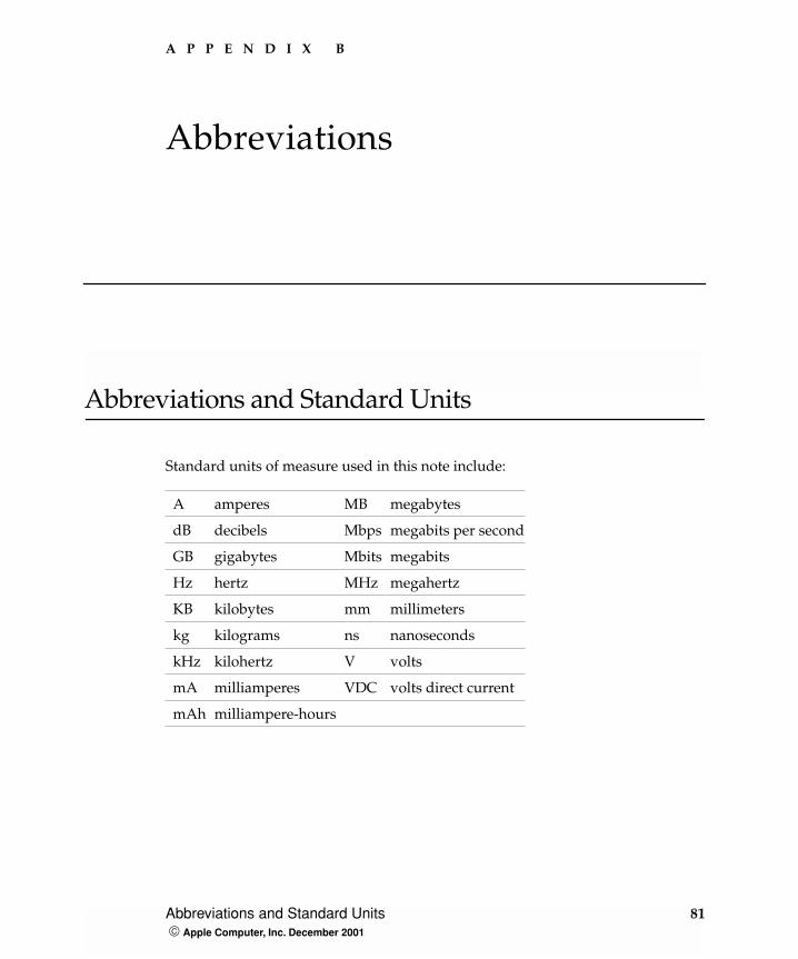
A P P E N D I X B
B Abbreviations
Abbreviations and Standard Units
Standard units of measure used in this note include:
A amperes MB megabytes
dB decibels Mbps megabits per second
GB gigabytes Mbits megabits
Hz hertz MHz megahertz
KB kilobytes mm millimeters
kg kilograms ns nanoseconds
kHz kilohertz V volts
mA milliamperes VDC volts direct current
mAh milliampere-hours
Abbreviations and Standard Units 81 Apple Computer, Inc. December 2001
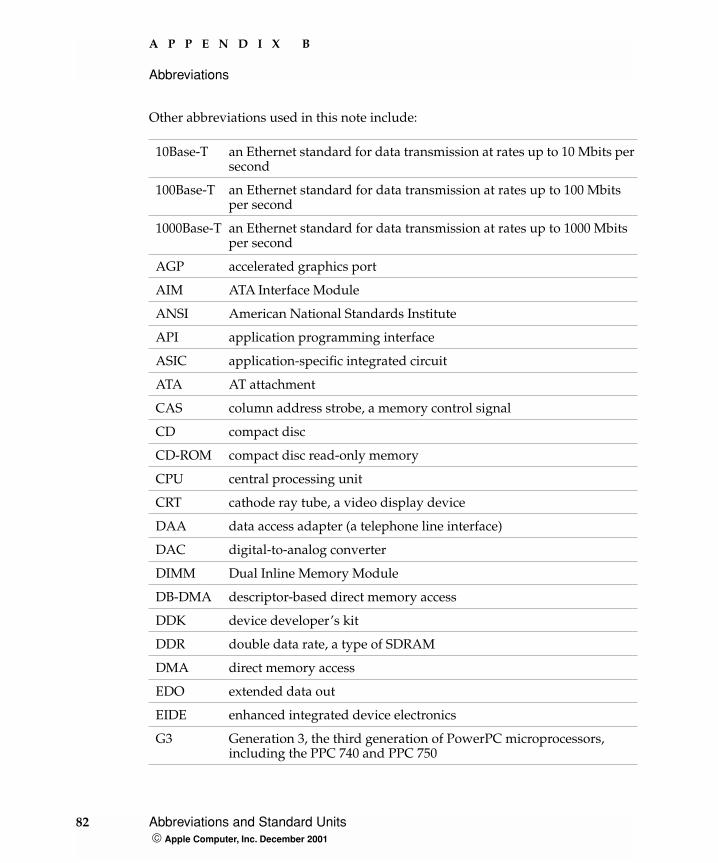
A P P E N D I X B
Abbreviations
Other abbreviations used in this note include:
10Base-T an Ethernet standard for data transmission at rates up to 10 Mbits per second
100Base-T an Ethernet standard for data transmission at rates up to 100 Mbits per second
1000Base-T an Ethernet standard for data transmission at rates up to 1000 Mbits per second
AGP accelerated graphics port
AIM ATA Interface Module
ANSI American National Standards Institute
API application programming interface
ASIC application-specific integrated circuit
ATA AT attachment
CAS column address strobe, a memory control signal
CD compact disc
CD-ROM compact disc read-only memory
CPU central processing unit
CRT cathode ray tube, a video display device
DAA data access adapter (a telephone line interface)
DAC digital-to-analog converter
DIMM Dual Inline Memory Module
DB-DMA descriptor-based direct memory access
DDK device developer’s kit
DDR double data rate, a type of SDRAM
DMA direct memory access
EDO extended data out
EIDE enhanced integrated device electronics
G3 Generation 3, the third generation of PowerPC microprocessors, including the PPC 740 and PPC 750
82 Abbreviations and Standard Units Apple Computer, Inc. December 2001
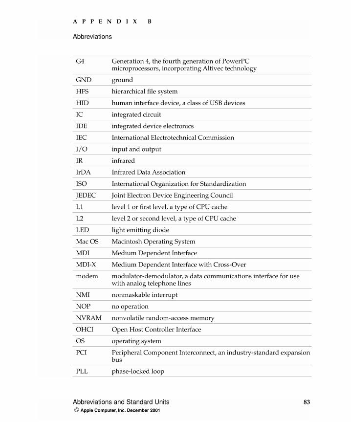
A P P E N D I X B
Abbreviations
G4 Generation 4, the fourth generation of PowerPC microprocessors, incorporating Altivec technology
GND ground
HFS hierarchical file system
HID human interface device, a class of USB devices
IC integrated circuit
IDE integrated device electronics
IEC International Electrotechnical Commission
I/O input and output
IR infrared
IrDA Infrared Data Association
ISO International Organization for Standardization
JEDEC Joint Electron Device Engineering Council
L1 level 1 or first level, a type of CPU cache
L2 level 2 or second level, a type of CPU cache
LED light emitting diode
Mac OS Macintosh Operating System
MDI Medium Dependent Interface
MDI-X Medium Dependent Interface with Cross-Over
modem modulator-demodulator, a data communications interface for use with analog telephone lines
NMI nonmaskable interrupt
NOP no operation
NVRAM nonvolatile random-access memory
OHCI Open Host Controller Interface
OS operating system
PCI Peripheral Component Interconnect, an industry-standard expansion bus
PLL phase-locked loop
Abbreviations and Standard Units 83 Apple Computer, Inc. December 2001
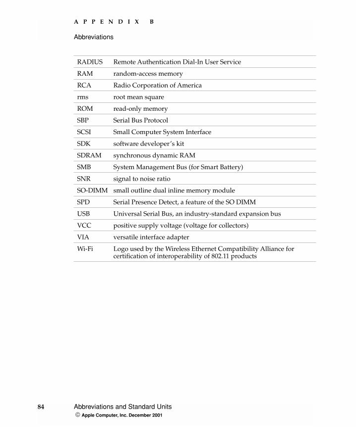
A P P E N D I X B
Abbreviations
RADIUS Remote Authentication Dial-In User Service
RAM random-access memory
RCA Radio Corporation of America
rms root mean square
ROM read-only memory
SBP Serial Bus Protocol
SCSI Small Computer System Interface
SDK software developer’s kit
SDRAM synchronous dynamic RAM
SMB System Management Bus (for Smart Battery)
SNR signal to noise ratio
SO-DIMM small outline dual inline memory module
SPD Serial Presence Detect, a feature of the SO DIMM
USB Universal Serial Bus, an industry-standard expansion bus
VCC positive supply voltage (voltage for collectors)
VIA versatile interface adapter
Wi-Fi Logo used by the Wireless Ethernet Compatibility Alliance for certification of interoperability of 802.11 products
84 Abbreviations and Standard Units Apple Computer, Inc. December 2001
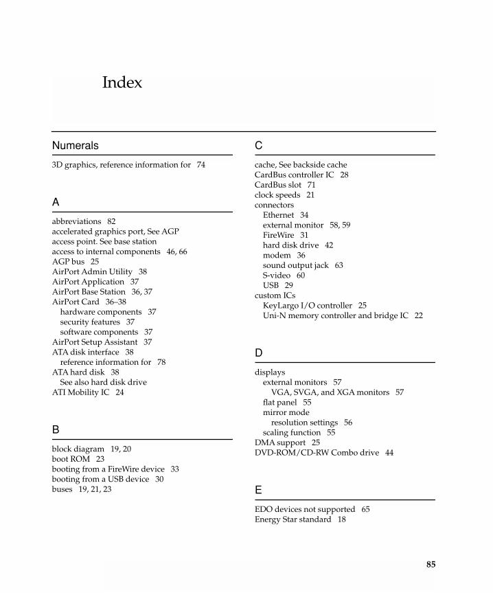
Index
Numerals
3D graphics, reference information for 74
A
abbreviations 82accelerated graphics port, See AGPaccess point. See base stationaccess to internal components 46, 66AGP bus 25AirPort Admin Utility 38AirPort Application 37AirPort Base Station 36, 37AirPort Card 36–38
hardware components 37security features 37software components 37
AirPort Setup Assistant 37ATA disk interface 38
reference information for 78ATA hard disk 38
See also hard disk driveATI Mobility IC 24
B
block diagram 19, 20boot ROM 23booting from a FireWire device 33booting from a USB device 30buses 19, 21, 23
C
cache, See backside cacheCardBus controller IC 28CardBus slot 71clock speeds 21connectors
Ethernet 34external monitor 58, 59FireWire 31hard disk drive 42modem 36sound output jack 63S-video 60USB 29
custom ICsKeyLargo I/O controller 25Uni-N memory controller and bridge IC 22
D
displaysexternal monitors 57
VGA, SVGA, and XGA monitors 57flat panel 55mirror mode
resolution settings 56scaling function 55
DMA support 25DVD-ROM/CD-RW Combo drive 44
E
EDO devices not supported 65Energy Star standard 18
85
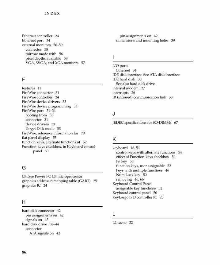
I N D E X
Ethernet controller 24Ethernet port 34external monitors 56–59
connector 58mirrow mode with 56pixel depths available 58VGA, SVGA, and XGA monitors 57
F
features 11FireWire connector 31FireWire controller 24FireWire device drivers 33FireWire device programming 33FireWire port 31–34
booting from 33connector 31device drivers 33Target Disk mode 33
FireWire, reference information for 79flat panel display 55function keys, alternate functions of 52Function-keys checkbox, in Keyboard control
panel 50
G
G4, See Power PC G4 microprocessorgraphics address remapping table (GART) 25graphics IC 24
H
hard disk connector 42pin assignments on 42signals on 43
hard disk drive 38–44connector
ATA signals on 43
pin assignments on 42dimensions and mounting holes 39
I
I/O portsEthernet 34
IDE disk interface. See ATA disk interfaceIDE hard disk 38
See also hard disk driveinternal modem 27interrupts 26IR (infrared) communication link 38
J
JEDEC specifications for SO-DIMMs 67
K
keyboard 46–54control keys with alternate functions 54effect of Function-keys checkbox 50Fn key 50function keys, user assignable 52keys with multiple functions 46Num Lock key 50removing 46, 66
Keyboard Control Panelassignable key functions 52
Keyboard control panel 50KeyLargo I/O controller IC 25
L
L2 cache 22
86
I N D E X
M
Mac OS 9, reference information for 76machine identification 17memory interleaving not supported 69microprocessor 21microprocessor clock speeds 21mirror mode 56
resolution settings for 56modem 27, 36monitor connector 58
N
NTSC video monitor 60
O
Open Firmware 16Open Firmware, reference information for 76
P, Q
PAL video monitor 60PCI bus 25peripheral devices 15pointing device 45power controller IC 28power saving modes 17, 28PowerPC G4 microprocessor 21
R
RAM expansion 65–70EDO devices not supported 65maximum current limits 70memory interleaving not supported 69module sizes 69
SDRAM device specifications 68sizes of SO-DIMMs 65
RAM expansion modulecapacities 69
ROM, See boot ROM
S
scaling of display images 55SCSI Disk mode 33SDRAM devices 65
specifications of 68serial presence detect, on SO-DIMM 68Sleep mode 17SO-DIMMs 65
address multiplexing on 69configurations 69electrical design of 67electrical limits for 70mechanical design of 67SDRAM device specifications 68serial presence detect on 68
sound circuitry 27sound specifications 62sound system 61–63
input sources 62built-in microphone 62
internal speakers 63output devices 63
speakers 63SuperDrive 44SVGA monitors 57S-video connector 60system software 16
Idle mode 17machine identification 17Open Firmware 16power saving modes 17Sleep mode 17
87
I N D E X
T
Target Disk mode 333D graphics, reference information for 74trackball 45trackpad 45
U
Uni-N memory controller and bridge IC 22units of measure 81Universal Serial Bus. See USB portsUSB connectors 29USB controller IC 26USB ports 29–31
booting from 30connectors 29data transfer speeds 26, 30
USB, reference information for 78
V
VGA monitors 57video display
controller IC 24subsystem architecture 24
video monitors 57See also external monitors
video port 60
W
wireless LAN module 28, 36–38base station 36, 37hardware components 37security features 37software components 37
X, Y, Z
XGA monitors 57
88