powerbuilt hotrod 5 gal air compressor - alltrade tools oil lubricated air compr essor is designed...
TRANSCRIPT
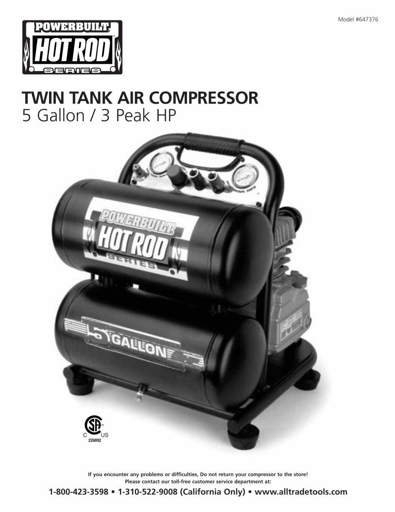
Model #647376
TWIN TANK AIR COMPRESSOR5 Gallon / 3 Peak HP
226892
If you encounter any problems or difficulties, Do not return your compressor to the store!Please contact our toll-free customer service department at:
1-800-423-3598 • 1-310-522-9008 (California Only) • www.alltradetools.com
It is the owner and/or operator’s responsibility to study all WARNINGS, operating, and maintenance instructions contained on the product labeland instruction manual prior to operation of this unit. The owner/operator shall retain product instructions for future reference.
The owner and/or operator is responsible for maintenance, maintaining all decals or warning labels and while in use, maintaining the unit ingood working order. If the owner and/or operator is not fluent in English, Spanish, or French, the product warnings and instructions shall beread and discussed in the operator’s native language by the purchaser/owner or his designee. Make sure that the operator comprehends itscontents. Safety information shall be emphasized and understood prior to usage. The air compressor shall be inspected per the operatinginstructions.
Users of this air compressor must fully understand these instructions. Each person operating this air compressor must also be of sound mindand body and must not be under the influence of any substance that might impair their vision, dexterity, or judgment.
Protect yourself and others by observing all safety information.
Failure to comply with instructions could result in personal injury and/or property damage!
If you encounter any problems or difficulties, please contact our Consumer Helpline:Phone: 1-800-423-3598E-Mail: [email protected]
TABLE OF CONTENTS
Specifications . . . . . . . . . . . . . . . . . . . . . . . . . . . . . . . . . . . . . . . . . . . . . . . . . . . . . . . . . . . . . . . . . . . . . . . . . . . . . . . . . . . . . . . . . . . . . . . . . 1
Introduction . . . . . . . . . . . . . . . . . . . . . . . . . . . . . . . . . . . . . . . . . . . . . . . . . . . . . . . . . . . . . . . . . . . . . . . . . . . . . . . . . . . . . . . . . . . . . . . . . . 2
Safety Alert. . . . . . . . . . . . . . . . . . . . . . . . . . . . . . . . . . . . . . . . . . . . . . . . . . . . . . . . . . . . . . . . . . . . . . . . . . . . . . . . . . . . . . . . . . . . . . . . . . . 2
Unpacking & Inspection . . . . . . . . . . . . . . . . . . . . . . . . . . . . . . . . . . . . . . . . . . . . . . . . . . . . . . . . . . . . . . . . . . . . . . . . . . . . . . . . . . . . . . . . . 2
Safety Warnings . . . . . . . . . . . . . . . . . . . . . . . . . . . . . . . . . . . . . . . . . . . . . . . . . . . . . . . . . . . . . . . . . . . . . . . . . . . . . . . . . . . . . . . . . . . . . . . 3
Installation and Location. . . . . . . . . . . . . . . . . . . . . . . . . . . . . . . . . . . . . . . . . . . . . . . . . . . . . . . . . . . . . . . . . . . . . . . . . . . . . . . . . . . . . . . . . 5
Grounding Instructions . . . . . . . . . . . . . . . . . . . . . . . . . . . . . . . . . . . . . . . . . . . . . . . . . . . . . . . . . . . . . . . . . . . . . . . . . . . . . . . . . . . . . . . . . . 5
Compressor Features . . . . . . . . . . . . . . . . . . . . . . . . . . . . . . . . . . . . . . . . . . . . . . . . . . . . . . . . . . . . . . . . . . . . . . . . . . . . . . . . . . . . . . . . . . . 7
Assembly Instructions . . . . . . . . . . . . . . . . . . . . . . . . . . . . . . . . . . . . . . . . . . . . . . . . . . . . . . . . . . . . . . . . . . . . . . . . . . . . . . . . . . . . . . . . . . . 9
Operation . . . . . . . . . . . . . . . . . . . . . . . . . . . . . . . . . . . . . . . . . . . . . . . . . . . . . . . . . . . . . . . . . . . . . . . . . . . . . . . . . . . . . . . . . . . . . . . . . . . . 10
Maintenance . . . . . . . . . . . . . . . . . . . . . . . . . . . . . . . . . . . . . . . . . . . . . . . . . . . . . . . . . . . . . . . . . . . . . . . . . . . . . . . . . . . . . . . . . . . . . . . . . 11
Troubleshooting Guide . . . . . . . . . . . . . . . . . . . . . . . . . . . . . . . . . . . . . . . . . . . . . . . . . . . . . . . . . . . . . . . . . . . . . . . . . . . . . . . . . . . . . . . . . . 13
Parts List . . . . . . . . . . . . . . . . . . . . . . . . . . . . . . . . . . . . . . . . . . . . . . . . . . . . . . . . . . . . . . . . . . . . . . . . . . . . . . . . . . . . . . . . . . . . . . . . . . . . . 15
Parts Diagram. . . . . . . . . . . . . . . . . . . . . . . . . . . . . . . . . . . . . . . . . . . . . . . . . . . . . . . . . . . . . . . . . . . . . . . . . . . . . . . . . . . . . . . . . . . . . . . . . 16
Limited Warranty . . . . . . . . . . . . . . . . . . . . . . . . . . . . . . . . . . . . . . . . . . . . . . . . . . . . . . . . . . . . . . . . . . . . . . . . . . . . . . . . . . . . . . . . . . . . . . 17
Duty Cycle:This air compressor pump is capable of running continuously. However, in order to prolong the life of your air compressor, it is recommendedthat a 50% to 75% average duty cycle be maintained. Duty cycle refers to the percentage of time a compressor can safely run within a givenamount of time expressed as a ratio. Example: Oil lubricated compressors are typically rated at a 50% duty cycle, meaning that the compressormotor can run about 50% of the total time it is being used to supply air to a tool. During the ON time, the motor is running to pressurize thetank. During the OFF time, the motor is stopped and the tools are running off on the pressurized air stored in the tank. If your air tools aredraining pressure off of the tank too quickly, the compressor motor must run more than 50% of the time the compressor is in use. This canlead to overheating and will significantly shorten the life of the compressor.
1
SPECIFICATIONSTwo Pole Induction Motor 3400 RPM
Power 115V, 60 Hz, 15 Amps
Air Delivery5.1 SCFM output @ 40 PSI4.1 SCFM output @ 90 PSI
Maximum Pressure 125 PSI
Duty Cycle 75%
3.0 Peak HP / 1.3 Running HP
5 Gallon Twin Stack Air Tank
Oil Lubricated Direct Drive Pump
Cast Iron Cylinder
Thermal Overload Protection for Safety
High Flow Regulator for Precision Air Flow Control
Tank and Outlet Pressure Gauges
Dual Quick Connect Coupler
INTRODUCTION
This oil lubricated air compressor is designed for Household Use Only and is not intended for commercial applications. It is well suited for do-it-yourselfers with a variety of automotive and home uses.
This instruction manual is intended for your benefit. Please read and follow the safety, installation, maintenance and troubleshooting stepsdescribed within to ensure your safety and satisfaction. The contents of this instruction manual are based upon the latest product informationavailable at the time of publication. The manufacturer reserves the right to make product changes at any time without notice.
SAFETY ALERT
READ AND UNDERSTAND THIS ENTIRE INSTRUCTION MANUAL BEFORE ATTEMPTING TO ASSEMBLE, INSTALL, OPERATE OR MAINTAIN THIS AIR COMPRESSOR. FAILURE TO COMPLY
WITH THE INSTRUCTIONS MAY RESULT IN SERIOUS PERSONAL INJURY AND/OR PROPERTY DAMAGE!
The following signal words are used to emphasize safety warnings that must be followed when using this air compressor:
Indicates an imminently hazardous situation that, if not avoided, WILL result in death or serious injury.
Indicates a potentially hazardous situation that, if not avoided, COULD result in death or serious injury.
Indicates a potentially hazardous situation that, if not avoided, MAY result in minor or moderate injury.
Indicates important information which if not followed, MAY cause damage to equipment.
UNPACKING & INSPECTION
After opening the carton, unpack your new air compressor and related parts & accessories. Please inspect it carefully for any damage that may have occurred during transit. Please check it against the photograph on carton. If any parts are missing, please contact our ConsumerHelpline:Phone: 1-800-423-3598E-Mail: [email protected]
DO NOT OPERATE THIS AIR COMPRESSOR IF DAMAGED DURING SHIPMENT, HANDLING OR MISUSE. DAMAGE MAY RESULT IN BURSTING, WHICH CAN CAUSE SERIOUS INJURY OR PROPERTY DAMAGE.
ALL DAMAGED PARTS MUST BE REPAIRED OR REPLACED AS NEEDED PRIOR TO OPERATING THIS AIR COMPRESSOR.
Check to see that all nuts, bolts and fittings are secure before putting this air compressor into service. If you have any questions, or requireassistance with damaged or missing parts, please contact our Consumer Helpline:Phone: 1-800-423-3598E-Mail: [email protected]
Please have the serial number, model number, date of purchase, and parts list (with missing parts identified) available for reference whencalling.
MODEL NUMBER: _______________________________________
SERIAL NUMBER: _______________________________________
DATE of PURCHASE: _____________________________________
2
DANGER
SAFETY WARNINGS
READ ALL SAFETY WARNINGS BEFORE USING AIR COMPRESSOR.
GENERAL SAFETY WARNINGS:• Keep work area clean. Messy areas and cluttered workbenches invite personal injury and/or property damage.• Keep children and visitors away. All children should be kept away from the work area. DO NOT let children handle the compressor or
extension cord. Maintain a safe distance for any person near the work area.• Operating any tools or equipment under the influence of drugs, alcohol, or medication can cause personal injury to yourself and others.• Wear proper apparel. Remove your jewelry before using air compressor. Do not wear loose clothing, necklaces, rings, bracelets, or other
jewelry, which may get caught in moving parts. Nonskid footwear and electrically non-conductive gloves are highly suggested while working.Wear protective hair covering to contain long hair.
• Protect your eyes. The operation of any air compressor can result in foreign objects being thrown into the eyes, which can result in severeeye damage. Always wear eye protection that meets ANSI Z28.1 specifications during air compressor operation. Eyeglasses are not alwayssafety glasses.
• Be responsible for your hearing. Wear hearing protection during extended periods of operation.• Use the right tool. Use tools properly and for their intended task. Do not force a small tool to do the job of a heavy-duty tool. Using the
right tool to do the right job will make doing the job safer.• Check damaged parts before use of any air tools or attachments. A guard or other part that is damaged should be carefully checked to
ensure that it will operate properly and perform its intended function. Check for misalignment or binding of moving parts, breakage ofparts, mounting, or any other conditions that may affect tool operation. A guard or other part that is damaged should be properly replaced.See replacement parts list for additional details.
• Avoid unintentional starting. Be sure that your air compressor is in the OFF position before plugging it into a power cord or electricalreceptacle.
• Store all maintenance tools away from the immediate area before turning ON your air compressor.• Do not overreach. Proper footing and balance is a must at all times while using tools. Unstable support may lead to personal injury. Do not
stand on the tool. Serious injury could result if the tool tips over or you accidentally contact tool.• Never leave the air compressor running unattended. Always turn the power to the OFF position and do not leave the air compressor until
it comes to a complete stop.• When using air accessories, consult the owner’s manual provided by the manufacturer. The use of improper accessories may cause risk of
injury to yourself and others.• Always make sure the tool is in the OFF position and unplugged from the electrical receptacle when making adjustments, changing parts, or
performing any maintenance.• Secure work. When possible, the use of clamps or a holding device is much safer than holding the work piece with your hands.• Keep protective guards in place and in proper working condition.• Maintain tools and equipment with care. They will function better and more safely when kept clean and in good working condition. Keeping
the air compressor clean, dry, and free of grime will add to its life and performance.• Childproof the workshop. The use of master switches and padlocks is highly recommended. Remove starter keys where applicable.
• SOME DUST CREATED BY SPRAYING, BLOWING, POWER SANDING, SAWING, GRINDING, DRILLING AND OTHER CONSTRUCTIONACTIVITIES CONTAINS CHEMICALS KNOWN TO THE STATE OF CALIFORNIA TO CAUSE CANCER, BIRTH DEFECTS OR OTHERREPRODUCTIVE HARM. REDUCE YOUR EXPOSURE TO THESE CHEMICALS BY WEARING APPROVED SAFETY EQUIPMENT SUCH AS DUSTMASKS THAT ARE DESIGNED TO FILTER OUT MICROSCOPIC PARTICLES.
• USE OF THIS PRODUCT WILL EXPOSE YOU TO CHEMICALS KNOWN TO THE STATE OF CALIFORNIA TO CAUSE CANCER, BIRTH DEFECTS,AND REPRODUCTIVE HARM. AVOID INHALING VAPORS AND DUST. WASH HANDS AFTER USING.
• THIS PRODUCT CONTAINS CHEMICALS, INCLUDING LEAD, KNOWN TO THE STATE OF CALIFORNIA TO CAUSE CANCER, BIRTH DEFECTS,AND REPRODUCTIVE HARM. WASH HANDS AFTER HANDLING.
• HANDLING THE POWER CORD ON THIS PRODUCT MAY EXPOSE YOU TO LEAD, A CHEMICAL KNOWN TO THE STATE OF CALIFORNIA TOCAUSE CANCER AND BIRTH DEFECTS OR OTHER REPRODUCTIVE HARM. WASH HANDS AFTER HANDLING.
3
DRAIN LIQUID FROM AIR TANK DAILY• Use the drain valve located on the bottom of the lower air tank to drain. Failure to properly drain liquid from the tank will cause rust from
moisture buildup, which weakens the tank and could lead to a violent tank explosion. Periodically inspect the tanks for unsafe conditionssuch as corrosion, cracked welds, and leaks.
• Release air slowly when draining moisture or depressurizing the air compressor. Fast moving air will stir up dust, dirt and debris that maybe harmful.
RISK OF FIRE OR EXPLOSIONAvoid dangerous environments. Do not spray combustible/flammable liquid in a confined area. Spray area must be well ventilated. Do notsmoke while spraying or spray where spark or flame is present. Arcing parts — keep compressor at least 20’ away from spraying area and allexplosive vapors. Do not use compressor near gasoline or other flammable materials. Operate the air compressor in a well-ventilated area.Do not direct paint or other spray material towards the compressor. Read and follow all safety instructions for the material you are spraying.Be sure to use an approved respirator designed for use with your specific application.
RISK OF INJURYDo not direct air stream at body. Use eye protection. Compressor starts automatically. Do not touch MOVING PARTS. Keep guards in place.Compressor does not supply breathable air.
RISK OF BURSTING• Do not adjust regulator to result in output pressure greater than marked maximum pressure of attachment. If a regulator has not been
installed, use only attachment rated at 200 PSI or higher. Do not weld on or repair tank — A DAMAGED TANK MUST BE REPLACEDIMMEDIATELY. Do not operate without proper safety valve in place.
• Never attempt to repair or make modifications to the tank or its attachments. Welding, drilling, or any other modifications may weakenthe tank, which may result in damage from rupture or explosion. Never remove or attempt to adjust the pressure switch, safety valve, orother components that control tank pressure. Never substitute parts or attempt to alter the factory set operating pressures.
RISK OF ELECTRICAL SHOCKDisconnect air compressor from power source before servicing. USE PROPERLY grounded ELECTRICAL CONNECTIONS — DO NOT usegrounding adaptors. Do not use in wet or damp locations or expose to rain. Keep all connections dry and off the ground. Do not allowpower cords to come into contact with water. Do not touch the plug with wet hands. Do not pull on the electrical cord to disconnect fromthe power outlet. Store air compressor indoors when not in use. Any electrical wiring or repairs performed on this air compressor should bedone by authorized service personnel in accordance with federal and local electrical codes.
RISK TO BREATHING• This air compressor is not designed, nor intended for the supply of breathable quality air. Air produced by this unit may contain carbon
monoxide or other toxic vapors. Do not inhale air from the compressor or from a breathing device connected to it.• Operate the air compressor in a well-ventilated area. Read and follow all safety instructions for the material you are spraying. Be sure to
use an approved respirator designed for use with your specific application.
RISK OF BURNSTouching exposed metal such as the compressor head or exhaust tube can result in serious burns. Keep hands and fingers away fromexposed metal parts on air compressor during or immediately after operation. Air compressors generate significant heat during normaloperation and will remain hot for some time after use. Do not reach around protective shrouds or attempt any maintenance until compressorhas been allowed to cool.
RISK OF FLYING OBJECTSDo not direct compressed air stream at people or pets. The powerful compressed air stream can damage exposed skin and easily propel loosedirt and other small objects at high-speed, resulting in serious injury. Always wear eye protection that meets ANSI Z28.1 specifications. Useonly OSHA approved air blowguns. Never leave a pressurized air compressor unattended. Shut OFF air compressor and relieve pressurebefore performing maintenance or repairs. Do not move the air compressor while the air tank is pressurized. Never attempt to move the aircompressor by pulling on the air hose.
4
DANGER
RISK OF FALLINGPortable air compressors can fall from a table, workbench, or roof causing damage to the compressor and could result in serious injury ordeath to the operator. Always operate air compressor in a stable and secure position to prevent accidental movement of the unit. Neveroperate air compressor on a roof or other elevated position. Use additional air hose to reach high locations.
RISK OF PROPERTY DAMAGE WHEN TRANSPORTING COMPRESSOROil can leak or spill and could result in fire or breathing hazard, serious injury or death. Oil leaks will damage carpet, paint, or other surfacesin vehicles or trailers.
AIR TOOLS AND ACCESSORIESDo not exceed the pressure rating of any air tools, spray guns, air accessories, or inflatables. Excess pressure can cause them to explode,resulting in serious injury. Follow the manufacturers recommended pressure settings for all air tools and air accessories.
INSTALLATION AND LOCATION
In order to avoid damaging the air compressor, do not allow the unit to be tilted more than 10º from the normal horizontal position whenoperating.
The compressor must be run with the rubber feet resting on a flat and stable horizontal surface.
The air compressor must be used in a clean and well-ventilated area. The compressor requires an unobstructed airflow and must be located aminimum of 20 inches from any walls or other obstructions that may prevent proper ventilation. DO NOT place air compressor in an area:• Where there is evidence of oil or gas leaks.• Where flammable gas vapors or materials may be present.• Where air temperatures fall below 32ºF or exceed 104ºF.• Where extremely dirty air or water could be drawn into the air compressor.
SERIOUS INJURY OR DEATH MAY OCCUR IF ELECTRICAL SPARKS FROM MOTOR AND PRESSURE SWITCH COME IN CONTACT WITH FLAMMABLE VAPORS, COMBUSTIBLE DUST, GASES OR OTHER COMBUSTIBLE MATERIALS. WHEN USING THE
AIR COMPRESSOR FOR SPRAYING PAINT, PLACE THE AIR COMPRESSOR AS FAR AWAY FROM THE WORK AREA AS POSSIBLE,USING EXTRA LENGTHS OF AIR HOSE TO EXTEND THE WORKING REACH INSTEAD OF EXTENSION CORDS.
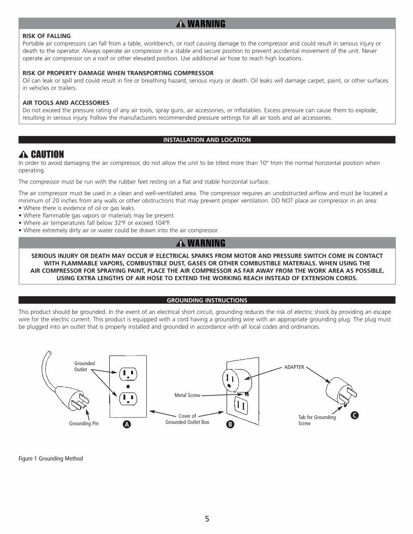
GROUNDING INSTRUCTIONS
This product should be grounded. In the event of an electrical short circuit, grounding reduces the risk of electric shock by providing an escapewire for the electric current. This product is equipped with a cord having a grounding wire with an appropriate grounding plug. The plug mustbe plugged into an outlet that is properly installed and grounded in accordance with all local codes and ordinances.
5
Figure 1 Grounding Method
Grounding Pin
GroundedOutlet
Cover ofGrounded Outlet Box
Metal Screw
A BTab for GroundingScrew
C
ADAPTER
IMPROPER INSTALLATION OF THE GROUNDING PLUG CAN RESULT IN A RISK OF ELECTRIC SHOCK. IF REPAIR OR REPLACEMENT OF THECORD IS NECESSARY, DO NOT CONNECT THE GROUNDING WIRE TO EITHER FLAT BLADE TERMINAL. THE WIRE WITH GREEN INSULATIONWITH OR WITHOUT YELLOW STRIPES IS THE GROUNDING WIRE.
THIS PRODUCT IS FOR USE ON A NOMINAL 120-VOLT CIRCUIT AND HAS A THREE-PRONG GROUNDING PLUG THAT LOOKS LIKE THE PLUGILLUSTRATED IN FIGURE 1. A TEMPORARY ADAPTER SIMILAR TO THE ADAPTER ILLUSTRATED IN SKETCH B AND C (SEE PAGE 5) MAY BEUSED TO CONNECT THIS PLUG TO A 2-POLE RECEPTACLE AS SHOWN IN ILLUSTRATION B WHEN A PROPERLY GROUNDED OUTLET IS NOTAVAILABLE. THE TEMPORARY ADAPTER SHALL BE USED ONLY UNTIL A PROPERLY GROUNDED OUTLET (ILLUSTRATION A) IS INSTALLED BY AQUALIFIED ELECTRICIAN. TAB FOR GROUNDING SCREW, LUG, OR SIMILAR PART EXTENDING FROM THE ADAPTER MUST BE CONNECTEDTO A PERMANENT GROUND SUCH AS A PROPERLY GROUNDED OUTLET BOX COVER. WHENEVER THE ADAPTER IS USED, IT MUST BE HELDIN PLACE BY A METAL SCREW.
THE USE OF A GFCI OUTLET IS STRONGLY RECOMMENDED. THE THIRD PRONG IS TO BE USED TO GROUND THE TOOL AND PROVIDEPROTECTION AGAINST ELECTRICAL SHOCK. NEVER REMOVE THE THIRD PRONG.
CHECK WITH A QUALIFIED ELECTRICIAN OR SERVICEMAN IF THE GROUNDING INSTRUCTIONS ARE NOT COMPLETELY UNDERSTOOD, OR IFIN DOUBT AS TO WHETHER THE PRODUCT IS PROPERLY GROUNDED. DO NOT MODIFY THE PLUG PROVIDED. IF IT WILL NOT FIT THEOUTLET, HAVE THE PROPER OUTLET INSTALLED BY A QUALIFIED ELECTRICIAN.
Extension CordsTHE USE OF AN EXTENSION CORD WITH THIS PRODUCT IS NOT RECOMMENDED as this can result in the loss of power to your aircompressor which can prevent the motor from starting or running properly. This can also cause your fuse to blow or circuit breaker to trip.Running your air compressor on an undersized extension cord will cause permanent damage to internal switches and overheating of the electric motor. Use an additional length of air hose rather than an extension cord.
If you must use an extension cord, it should be plugged into a GFCI found in circuit boxes or protected receptacles. Use only UL listed 3-wireextension cords that have a 3-blade grounding plug and a 3-slot receptacle that will accept the plug on the product. Make sure your extensioncord is in good condition. When using an extension cord, be sure to use one heavy enough to carry the current your product will draw. Refer tothe guide below for minimum gauge required for extension cords.
Use only extension cords that are intended for outdoor use. These cords are identified by a marking “ACCEPTABLE FOR USE WITH OUTDOORAPPLIANCES, STORE INDOORS WHEN NOT IN USE.” Examine extension cord before use. DO NOT USE DAMAGED EXTENSION CORDS. Do notpull on cord to disconnect from receptacle; always disconnect by pulling on plug. Keep cord away from heat and sharp edges. Always shut OFFthe air compressor AUTO/ON pressure switch before unplugging the compressor. Always disconnect the extension cord from the receptaclebefore disconnecting the product from the extension cord.
AVOID ELECTRICAL SHOCK HAZARD. NEVER USE THIS COMPRESSOR WITH A DAMAGED OR FRAYED ELECTRICAL CORD OR EXTENSION CORD. INSPECT ALL ELECTRICAL CORDS REGULARLY.
NEVER USE IN OR NEAR WATER OR IN ANY ENVIRONMENT WHERE ELECTRIC SHOCK IS POSSIBLE. TO REDUCE THE RISK OF ELECTROCUTION, KEEP ALL CONNECTIONS DRY AND OFF THE GROUND.
DO NOT TOUCH THE PLUG WITH WET HANDS.
Guard against electrical shock. Avoid body contact with grounded services such as pipes, ovens, stoves, and refrigerator enclosures. If notproperly grounded, this air compressor can incur the potential hazard of light trickle shock, particularly when used in damp locations. Ifelectrical shock occurs, there is the potential of secondary hazard such as your hands contacting an operating air tool.
COMPRESSOR FEATURES
6
DANGER
EXTENSION CORD LENGTH WIRE SIZE (AWG)
Up to 25 Feet 16
26 to 50 Feet 12
51 to 100 Feet 10
7
COMPRESSOR FEATURES
34
56
78
10
12
13
9
11
12
1
2
COMPRESSOR FEATURES
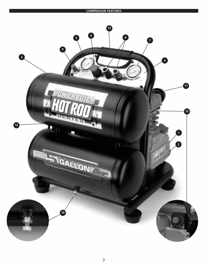
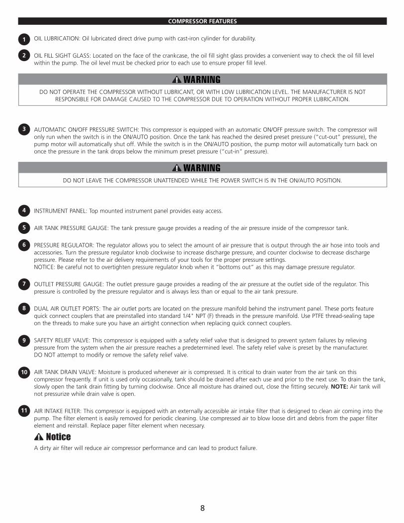
OIL LUBRICATION: Oil lubricated direct drive pump with cast-iron cylinder for durability.
OIL FILL SIGHT GLASS: Located on the face of the crankcase, the oil fill sight glass provides a convenient way to check the oil fill levelwithin the pump. The oil level must be checked prior to each use to ensure proper fill level.
DO NOT OPERATE THE COMPRESSOR WITHOUT LUBRICANT, OR WITH LOW LUBRICATION LEVEL. THE MANUFACTURER IS NOTRESPONSIBLE FOR DAMAGE CAUSED TO THE COMPRESSOR DUE TO OPERATION WITHOUT PROPER LUBRICATION.
AUTOMATIC ON/OFF PRESSURE SWITCH: This compressor is equipped with an automatic ON/OFF pressure switch. The compressor willonly run when the switch is in the ON/AUTO position. Once the tank has reached the desired preset pressure (“cut-out” pressure), thepump motor will automatically shut off. While the switch is in the ON/AUTO position, the pump motor will automatically turn back ononce the pressure in the tank drops below the minimum preset pressure (“cut-in” pressure).
DO NOT LEAVE THE COMPRESSOR UNATTENDED WHILE THE POWER SWITCH IS IN THE ON/AUTO POSITION.
INSTRUMENT PANEL: Top mounted instrument panel provides easy access.
AIR TANK PRESSURE GAUGE: The tank pressure gauge provides a reading of the air pressure inside of the compressor tank.
PRESSURE REGULATOR: The regulator allows you to select the amount of air pressure that is output through the air hose into tools andaccessories. Turn the pressure regulator knob clockwise to increase discharge pressure, and counter clockwise to decrease dischargepressure. Please refer to the air delivery requirements of your tools for the proper pressure settings. NOTICE: Be careful not to overtighten pressure regulator knob when it “bottoms out” as this may damage pressure regulator.
OUTLET PRESSURE GAUGE: The outlet pressure gauge provides a reading of the air pressure at the outlet side of the regulator. Thispressure is controlled by the pressure regulator and is always less than or equal to the air tank pressure.
DUAL AIR OUTLET PORTS: The air outlet ports are located on the pressure manifold behind the instrument panel. These ports featurequick connect couplers that are preinstalled into standard 1/4" NPT (F) threads in the pressure manifold. Use PTFE thread-sealing tape on the threads to make sure you have an airtight connection when replacing quick connect couplers.
SAFETY RELIEF VALVE: This compressor is equipped with a safety relief valve that is designed to prevent system failures by relievingpressure from the system when the air pressure reaches a predetermined level. The safety relief valve is preset by the manufacturer. DO NOT attempt to modify or remove the safety relief valve.
AIR TANK DRAIN VALVE: Moisture is produced whenever air is compressed. It is critical to drain water from the air tank on thiscompressor frequently. If unit is used only occasionally, tank should be drained after each use and prior to the next use. To drain the tank,slowly open the tank drain fitting by turning clockwise. Once all moisture has drained out, close the fitting securely. NOTE: Air tank willnot pressurize while drain valve is open.
AIR INTAKE FILTER: This compressor is equipped with an externally accessible air intake filter that is designed to clean air coming into thepump. The filter element is easily removed for periodic cleaning. Use compressed air to blow loose dirt and debris from the paper filterelement and reinstall. Replace paper filter element when necessary.
A dirty air filter will reduce air compressor performance and can lead to product failure.
8
1
2
11
10
9
8
7
6
5
4
3
COMPRESSOR FEATURES
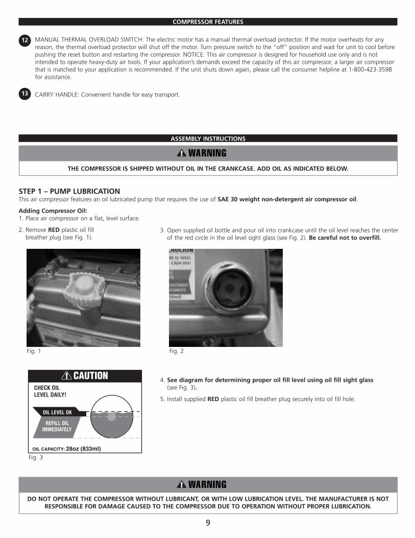
MANUAL THERMAL OVERLOAD SWITCH: The electric motor has a manual thermal overload protector. If the motor overheats for anyreason, the thermal overload protector will shut off the motor. Turn pressure switch to the “off” position and wait for unit to cool beforepushing the reset button and restarting the compressor. NOTICE: This air compressor is designed for household use only and is notintended to operate heavy-duty air tools. If your application’s demands exceed the capacity of this air compressor, a larger air compressorthat is matched to your application is recommended. If the unit shuts down again, please call the consumer helpline at 1-800-423-3598for assistance.
CARRY HANDLE: Convenient handle for easy transport.
ASSEMBLY INSTRUCTIONS
THE COMPRESSOR IS SHIPPED WITHOUT OIL IN THE CRANKCASE. ADD OIL AS INDICATED BELOW.
STEP 1 – PUMP LUBRICATIONThis air compressor features an oil lubricated pump that requires the use of SAE 30 weight non-detergent air compressor oil.
Adding Compressor Oil:1. Place air compressor on a flat, level surface.
2. Remove RED plastic oil fill breather plug (see Fig. 1).
4. See diagram for determining proper oil fill level using oil fill sight glass (see Fig. 3).
5. Install supplied RED plastic oil fill breather plug securely into oil fill hole.
DO NOT OPERATE THE COMPRESSOR WITHOUT LUBRICANT, OR WITH LOW LUBRICATION LEVEL. THE MANUFACTURER IS NOTRESPONSIBLE FOR DAMAGE CAUSED TO THE COMPRESSOR DUE TO OPERATION WITHOUT PROPER LUBRICATION.
9
13
12
CHECK OILLEVEL DAILY!
REFILL OILIMMEDIATELY
OIL LEVEL OK
OIL CAPACITY: 28oz (833ml)
CAUTION
3. Open supplied oil bottle and pour oil into crankcase until the oil level reaches the centerof the red circle in the oil level sight glass (see Fig. 2). Be careful not to overfill.
Fig. 2
Fig. 3
Fig. 1
STEP 2 – INSPECTION CHECKAssembly Check:In order to complete the assembly of your new air compressor, a careful inspection should be made to ensure that all of the parts are properlyaligned and securely fastened.
1. Inspect air filter to ensure that it is installed and secure.
2. Check oil fill level in crankcase.
OPERATION
INITIAL SETUP / BREAK-IN PROCEDURE:
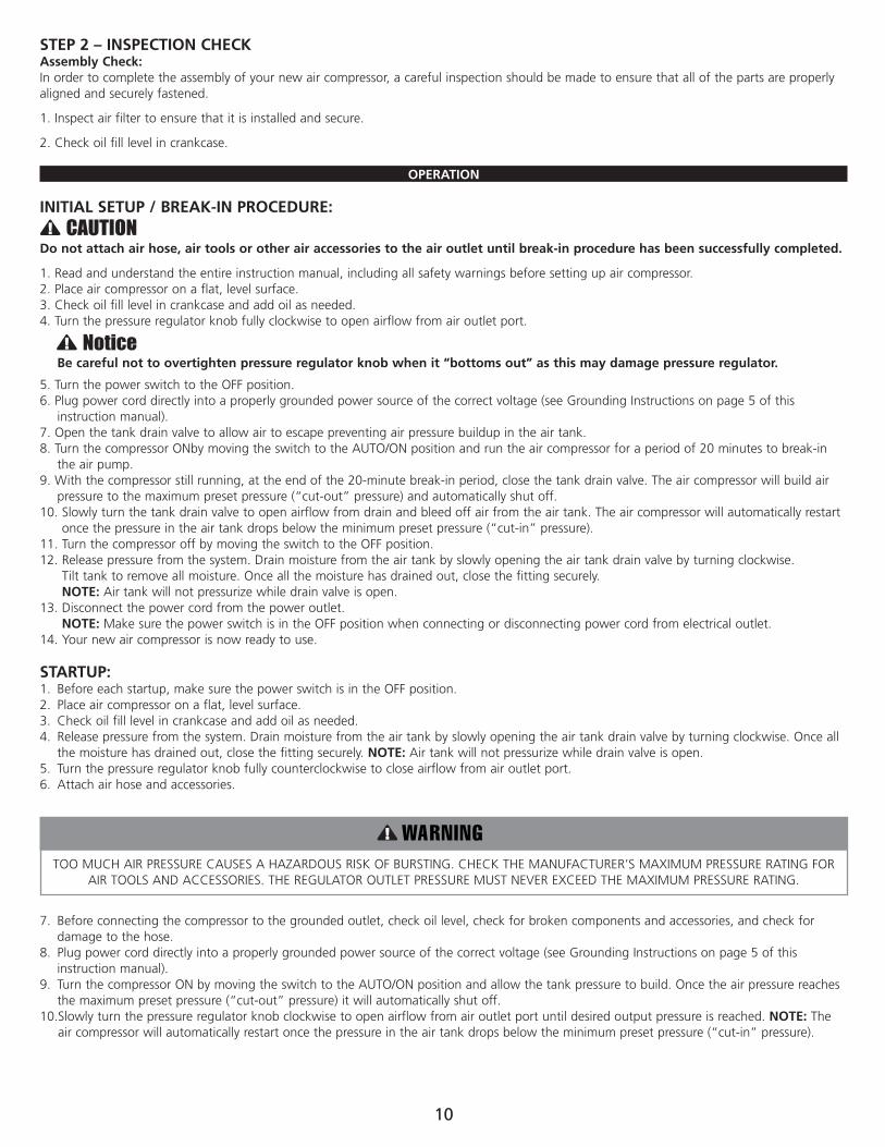
Do not attach air hose, air tools or other air accessories to the air outlet until break-in procedure has been successfully completed.
1. Read and understand the entire instruction manual, including all safety warnings before setting up air compressor.2. Place air compressor on a flat, level surface.3. Check oil fill level in crankcase and add oil as needed.4. Turn the pressure regulator knob fully clockwise to open airflow from air outlet port.
Be careful not to overtighten pressure regulator knob when it “bottoms out” as this may damage pressure regulator.
5. Turn the power switch to the OFF position.6. Plug power cord directly into a properly grounded power source of the correct voltage (see Grounding Instructions on page 5 of this
instruction manual).7. Open the tank drain valve to allow air to escape preventing air pressure buildup in the air tank.8. Turn the compressor ONby moving the switch to the AUTO/ON position and run the air compressor for a period of 20 minutes to break-in
the air pump.9. With the compressor still running, at the end of the 20-minute break-in period, close the tank drain valve. The air compressor will build air
pressure to the maximum preset pressure (“cut-out” pressure) and automatically shut off.10. Slowly turn the tank drain valve to open airflow from drain and bleed off air from the air tank. The air compressor will automatically restart
once the pressure in the air tank drops below the minimum preset pressure (“cut-in” pressure).11. Turn the compressor off by moving the switch to the OFF position.12. Release pressure from the system. Drain moisture from the air tank by slowly opening the air tank drain valve by turning clockwise.
Tilt tank to remove all moisture. Once all the moisture has drained out, close the fitting securely. NOTE: Air tank will not pressurize while drain valve is open.
13. Disconnect the power cord from the power outlet. NOTE: Make sure the power switch is in the OFF position when connecting or disconnecting power cord from electrical outlet.
14. Your new air compressor is now ready to use.
STARTUP:1. Before each startup, make sure the power switch is in the OFF position.2. Place air compressor on a flat, level surface.3. Check oil fill level in crankcase and add oil as needed.4. Release pressure from the system. Drain moisture from the air tank by slowly opening the air tank drain valve by turning clockwise. Once all
the moisture has drained out, close the fitting securely. NOTE: Air tank will not pressurize while drain valve is open.5. Turn the pressure regulator knob fully counterclockwise to close airflow from air outlet port.6. Attach air hose and accessories.
TOO MUCH AIR PRESSURE CAUSES A HAZARDOUS RISK OF BURSTING. CHECK THE MANUFACTURER’S MAXIMUM PRESSURE RATING FORAIR TOOLS AND ACCESSORIES. THE REGULATOR OUTLET PRESSURE MUST NEVER EXCEED THE MAXIMUM PRESSURE RATING.
7. Before connecting the compressor to the grounded outlet, check oil level, check for broken components and accessories, and check fordamage to the hose.
8. Plug power cord directly into a properly grounded power source of the correct voltage (see Grounding Instructions on page 5 of thisinstruction manual).
9. Turn the compressor ON by moving the switch to the AUTO/ON position and allow the tank pressure to build. Once the air pressure reachesthe maximum preset pressure (“cut-out” pressure) it will automatically shut off.
10.Slowly turn the pressure regulator knob clockwise to open airflow from air outlet port until desired output pressure is reached. NOTE: Theair compressor will automatically restart once the pressure in the air tank drops below the minimum preset pressure (“cut-in” pressure).
10
MAINTENANCE
DISCONNECT AIR COMPRESSOR FROM POWER SOURCE AND BLEED OFF ALL AIR PRESSURE BEFORE ATTEMPTING ANY MAINTENANCE OR REPAIR.
SHUTDOWN AND STORAGE:NOTE: NEVER stop the air compressor by unplugging it from the power outlet as this may result in damage to the compressor.
1. Turn the switch to the OFF position2. Disconnect the power cord from the power outlet. Disconnect the power cord from the power outlet by grabbing the plug (not the cord).
Loop around electric cord holder for storage.3. Turn the pressure regulator knob fully counterclockwise to close airflow from air outlet port. Check the outlet pressure gauge to ensure that
it reads 0 PSI.4. Remove the air hose and any air accessories.5. Drain moisture from the air tank by slowly opening the air tank drain valve by turning clockwise. Tilt tank to remove all moisture. Once all
the moisture has drained out, close the fitting securely.6. Allow the compressor to cool down.7. Wipe the air compressor clean and store it in a clean, dry, and non-freezing location.
WHEN PERFORMING ANY MAINTENANCE OR SERVICE:1. The air compressor must be turned off.2. Disconnect compressor from the power source.3. Open tank drain to bleed off all air pressure before attempting any maintenance or repair.4. Allow compressor to fully cool before attempting any maintenance or repair.
Check the air compressor frequently for any visible problems and follow maintenance procedures each time the compressor is used.
All air compressors contain maintenance parts that require periodic replacement. These used parts, including air filters and used lubricating oil,may contain regulated substances that must be disposed of in accordance with local, state, and federal laws and regulations.
1. Turn compressor off and release pressure from the system. Drain moisture from the air tank by slowly opening the air tank drain valve byturning clockwise. Tilt tank to remove all moisture. Once all the moisture has drained out, close the fitting securely.
2. Wipe the compressor clean.
MAINTENANCE CHECKLIST:
Daily:• Check oil level.• Drain accumulated liquid from tank.• Check for oil leaks.• Check for unusual noise and/or vibrations.• Check that all fasteners are secure.• Wipe compressor clean.
+ Apply a solution of soapy water around joints. Look for air bubbles around joints when compressor reaches the pressure cut-out limit and thepump turns off.
* The pump oil must be changed after the first 20 hours of operation. Thereafter, change oil every 200 hours of operation or every six months,whichever comes first. In harsh operating conditions, maintenance must be performed more frequently.
OIL CHANGE:Used lubricating oil may contain regulated substances that must be disposed of in accordance with local, state, and federal laws and regulations.
1. The air compressor must be turned OFF.2. Allow compressor to fully cool before attempting any maintenance or repair.3. Place a suitable oil drain pan below oil drain plug (see Fig. 4).
11
Weekly:• Inspect and clean air filter.• Clean breather holes on oil fill plug.
Monthly:• Check for air leaks.+
• Check safety relief valve.
Six months or 200 operating hours:*• Change compressor oil. Use only SAE
30 weight non-detergent aircompressor oil.
• Replace oil more frequently when usedin dusty operating environments.
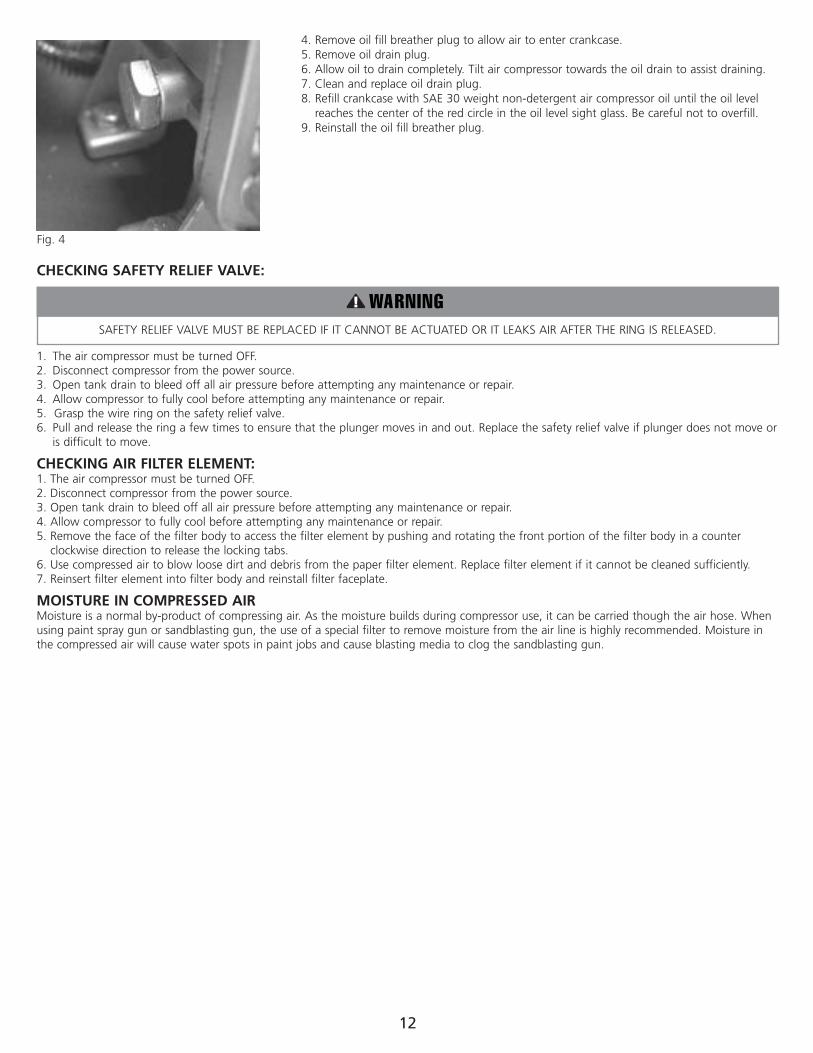
4. Remove oil fill breather plug to allow air to enter crankcase.5. Remove oil drain plug.6. Allow oil to drain completely. Tilt air compressor towards the oil drain to assist draining.7. Clean and replace oil drain plug.8. Refill crankcase with SAE 30 weight non-detergent air compressor oil until the oil level
reaches the center of the red circle in the oil level sight glass. Be careful not to overfill.9. Reinstall the oil fill breather plug.
CHECKING SAFETY RELIEF VALVE:
SAFETY RELIEF VALVE MUST BE REPLACED IF IT CANNOT BE ACTUATED OR IT LEAKS AIR AFTER THE RING IS RELEASED.
1. The air compressor must be turned OFF.2. Disconnect compressor from the power source.3. Open tank drain to bleed off all air pressure before attempting any maintenance or repair.4. Allow compressor to fully cool before attempting any maintenance or repair.5. Grasp the wire ring on the safety relief valve.6. Pull and release the ring a few times to ensure that the plunger moves in and out. Replace the safety relief valve if plunger does not move or
is difficult to move.
CHECKING AIR FILTER ELEMENT:1. The air compressor must be turned OFF.2. Disconnect compressor from the power source.3. Open tank drain to bleed off all air pressure before attempting any maintenance or repair.4. Allow compressor to fully cool before attempting any maintenance or repair.5. Remove the face of the filter body to access the filter element by pushing and rotating the front portion of the filter body in a counter
clockwise direction to release the locking tabs.6. Use compressed air to blow loose dirt and debris from the paper filter element. Replace filter element if it cannot be cleaned sufficiently.7. Reinsert filter element into filter body and reinstall filter faceplate.
MOISTURE IN COMPRESSED AIRMoisture is a normal by-product of compressing air. As the moisture builds during compressor use, it can be carried though the air hose. Whenusing paint spray gun or sandblasting gun, the use of a special filter to remove moisture from the air line is highly recommended. Moisture inthe compressed air will cause water spots in paint jobs and cause blasting media to clog the sandblasting gun.
12
Fig. 4
13
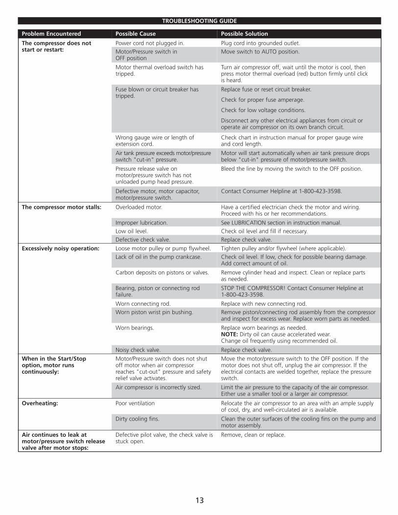
TROUBLESHOOTING GUIDE
Problem Encountered Possible Cause Possible Solution
The compressor does not start or restart:
Power cord not plugged in. Plug cord into grounded outlet.Motor/Pressure switch in OFF position
Move switch to AUTO position.
Motor thermal overload switch hastripped.
Turn air compressor off, wait until the motor is cool, thenpress motor thermal overload (red) button firmly until click is heard.
Fuse blown or circuit breaker hastripped.
Replace fuse or reset circuit breaker.
Check for proper fuse amperage.
Check for low voltage conditions.
Disconnect any other electrical appliances from circuit oroperate air compressor on its own branch circuit.
Wrong gauge wire or length ofextension cord.
Check chart in instruction manual for proper gauge wire and cord length.
Air tank pressure exceeds motor/pressureswitch "cut-in" pressure.
Motor will start automatically when air tank pressure dropsbelow "cut-in" pressure of motor/pressure switch.
Pressure release valve onmotor/pressure switch has notunloaded pump head pressure.
Bleed the line by moving the switch to the OFF position.
Defective motor, motor capacitor,motor/pressure switch.
Contact Consumer Helpline at 1-800-423-3598.
The compressor motor stalls: Overloaded motor. Have a certified electrician check the motor and wiring.Proceed with his or her recommendations.
Improper lubrication. See LUBRICATION section in instruction manual.Low oil level. Check oil level and fill if necessary.Defective check valve. Replace check valve.
Excessively noisy operation: Loose motor pulley or pump flywheel. Tighten pulley and/or flywheel (where applicable).Lack of oil in the pump crankcase. Check oil level. If low, check for possible bearing damage.
Add correct amount of oil.
Carbon deposits on pistons or valves. Remove cylinder head and inspect. Clean or replace parts as needed.
Bearing, piston or connecting rodfailure.
STOP THE COMPRESSOR! Contact Consumer Helpline at 1-800-423-3598.
Worn connecting rod. Replace with new connecting rod.Worn piston wrist pin bushing. Remove piston/connecting rod assembly from the compressor
and inspect for excess wear. Replace worn parts as needed.
Worn bearings. Replace worn bearings as needed. NOTE: Dirty oil can cause accelerated wear. Change oil frequently using recommended oil.
Noisy check valve. Replace check valve.
When in the Start/Stopoption, motor runscontinuously:
Motor/Pressure switch does not shutoff motor when air compressorreaches "cut-out" pressure and safetyrelief valve activates.
Move the motor/pressure switch to the OFF position. If themotor does not shut off, unplug the air compressor. If theelectrical contacts are welded together, replace the pressureswitch.
Air compressor is incorrectly sized. Limit the air pressure to the capacity of the air compressor.Either use a smaller tool or a larger air compressor.
Overheating: Poor ventilation Relocate the air compressor to an area with an ample supplyof cool, dry, and well-circulated air is available.
Dirty cooling fins. Clean the outer surfaces of the cooling fins on the pump andmotor assembly.
Air continues to leak atmotor/pressure switch releasevalve after motor stops:
Defective pilot valve, the check valve isstuck open.
Remove, clean or replace.
14
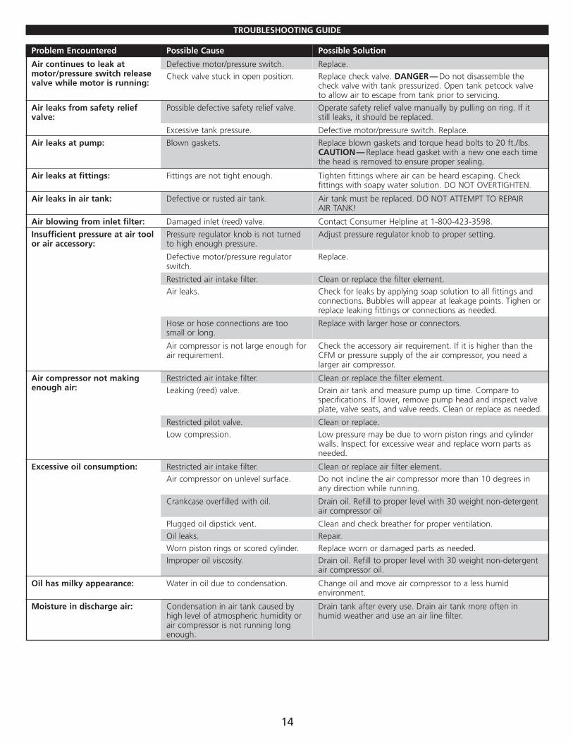
TROUBLESHOOTING GUIDE
Problem Encountered Possible Cause Possible Solution
Air continues to leak atmotor/pressure switch releasevalve while motor is running:
Defective motor/pressure switch. Replace.Check valve stuck in open position. Replace check valve. DANGER— Do not disassemble the
check valve with tank pressurized. Open tank petcock valveto allow air to escape from tank prior to servicing.
Air leaks from safety reliefvalve:
Possible defective safety relief valve. Operate safety relief valve manually by pulling on ring. If itstill leaks, it should be replaced.
Excessive tank pressure. Defective motor/pressure switch. Replace.
Air leaks at pump: Blown gaskets. Replace blown gaskets and torque head bolts to 20 ft./lbs.CAUTION— Replace head gasket with a new one each timethe head is removed to ensure proper sealing.
Air leaks at fittings: Fittings are not tight enough. Tighten fittings where air can be heard escaping. Checkfittings with soapy water solution. DO NOT OVERTIGHTEN.
Air leaks in air tank: Defective or rusted air tank. Air tank must be replaced. DO NOT ATTEMPT TO REPAIR AIR TANK!
Air blowing from inlet filter: Damaged inlet (reed) valve. Contact Consumer Helpline at 1-800-423-3598.
Insufficient pressure at air tool or air accessory:
Pressure regulator knob is not turnedto high enough pressure.
Adjust pressure regulator knob to proper setting.
Defective motor/pressure regulatorswitch.
Replace.
Restricted air intake filter. Clean or replace the filter element.Air leaks. Check for leaks by applying soap solution to all fittings and
connections. Bubbles will appear at leakage points. Tighen orreplace leaking fittings or connections as needed.
Hose or hose connections are toosmall or long.
Replace with larger hose or connectors.
Air compressor is not large enough forair requirement.
Check the accessory air requirement. If it is higher than theCFM or pressure supply of the air compressor, you need alarger air compressor.
Air compressor not makingenough air:
Restricted air intake filter. Clean or replace the filter element.Leaking (reed) valve. Drain air tank and measure pump up time. Compare to
specifications. If lower, remove pump head and inspect valveplate, valve seats, and valve reeds. Clean or replace as needed.
Restricted pilot valve. Clean or replace.Low compression. Low pressure may be due to worn piston rings and cylinder
walls. Inspect for excessive wear and replace worn parts asneeded.
Excessive oil consumption: Restricted air intake filter. Clean or replace air filter element.Air compressor on unlevel surface. Do not incline the air compressor more than 10 degrees in
any direction while running.
Crankcase overfilled with oil. Drain oil. Refill to proper level with 30 weight non-detergentair compressor oil
Plugged oil dipstick vent. Clean and check breather for proper ventilation.Oil leaks. Repair.Worn piston rings or scored cylinder. Replace worn or damaged parts as needed.Improper oil viscosity. Drain oil. Refill to proper level with 30 weight non-detergent
air compressor oil.
Oil has milky appearance: Water in oil due to condensation. Change oil and move air compressor to a less humidenvironment.
Moisture in discharge air: Condensation in air tank caused byhigh level of atmospheric humidity orair compressor is not running longenough.
Drain tank after every use. Drain air tank more often inhumid weather and use an air line filter.
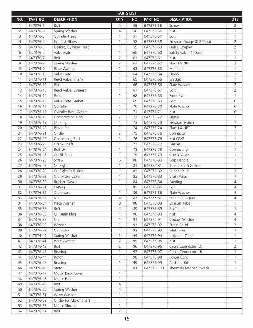
PARTS LIST
15
NO. PART NO. DESCRIPTION QTY NO. PART NO. DESCRIPTION QTY
1 647376-1 Bolt 4 55 647376-55 Screw 22 647376-2 Spring Washer 4 56 647376-56 Nut 13 647376-3 Cylinder Head 1 57 647376-57 Bolt 14 647376-4 Exhaust Elbow 1 58 647376-58 Pressure Guage (0-200psi) 25 647376-5 Gasket, Cylinder Head 1 59 647376-59 Quick Coupler 26 647376-6 Valve Plate 1 60 647376-60 Safety Valve (140psi) 17 647376-7 Bolt 2 61 647376-61 Nut 18 647376-8 Spring Washer 2 62 647376-62 Plug 1/8 NPT 29 647376-9 Plate Washer 2 63 647376-63 Manifold 110 647376-10 Valve Plate 1 64 647376-64 Elbow 111 647376-11 Reed Valve, Intake 1 65 647376-65 Bracket 112 647376-12 Pin 2 66 647376-66 Plate Washer 213 647376-13 Reed Valve, Exhaust 1 67 647376-67 Bolt 214 647376-14 Piston 1 68 647376-68 Front Plate 115 647376-15 Valve Plate Gasket 1 69 647376-69 Bolt 616 647376-16 Cylinder 1 70 647376-70 Plate Washer 617 647376-17 Cylinder Base Gasket 1 71 647376-71 Nut 618 647376-18 Compression Ring 2 72 647376-72 Sleeve 119 647376-19 Oil Ring 1 73 647376-73 Pressure Switch 120 647376-20 Piston Pin 1 74 647376-74 Plug 1/4 NPT 321 647376-21 Circlip 2 75 647376-75 Connector 122 647376-22 Connecting Rod 1 76 647376-76 Nut G3/8 123 647376-23 Crank Shaft 1 77 647376-77 Gasket 124 647376-24 Bolt LH 1 78 647376-78 Connecting 125 647376-25 Oil Fill Plug 1 79 647376-79 Check Valve 126 647376-26 Screw 6 80 647376-80 Grip Handle 127 647376-27 Oil Sight 1 81 647376-81 Tank 2 x 2.5 Gallon 128 647376-28 Oil Sight Seal Ring 1 82 647376-82 Rubber Plug 229 647376-29 Crankcase Cover 1 83 647376-83 Drain Valve 130 647376-30 Rubber Gasket 1 84 647376-84 Padding 431 647376-31 O-Ring 1 85 647376-85 Bolt 432 647376-32 Crankcase 1 86 647376-86 Plate Washer 433 647376-33 Nut 4 87 647376-87 Rubber Footpad 434 647376-34 Plate Washer 8 88 647376-88 Exhaust Tube 135 647376-35 Bolt 4 89 647376-89 Fin Tubing 136 647376-36 Oil Drain Plug 1 90 647376-90 Nut 437 647376-37 Nut 1 91 647376-91 Copper Washer 438 647376-38 Washer 1 92 647376-92 Strain Relief 239 647376-39 Capacitor 1 93 647376-93 Inlet Tube 140 647376-40 Spring Washer 2 94 647376-94 Unloader Tube 141 647376-41 Plate Washer 2 95 647376-95 Nut 142 647376-42 Bolt 2 96 647376-96 Cable Connector (O) 243 647376-43 Bearing 1 97 647376-97 Cable Connector (U) 144 647376-44 Rotor 1 98 647376-98 Power Cord 145 647376-45 Bearing 1 99 647376-99 Air Filter Kit 146 647376-46 Stator 1 100 647376-100 Thermal Overload Switch 147 647376-47 Motor Back Cover 148 647376-48 Motor Fan 149 647376-49 Bolt 450 647376-50 Spring Washer 451 647376-51 Wave Washer 152 647376-52 Circlip for Motor Shaft 153 647376-53 Motor Shroud 154 647376-54 Bolt 2
16
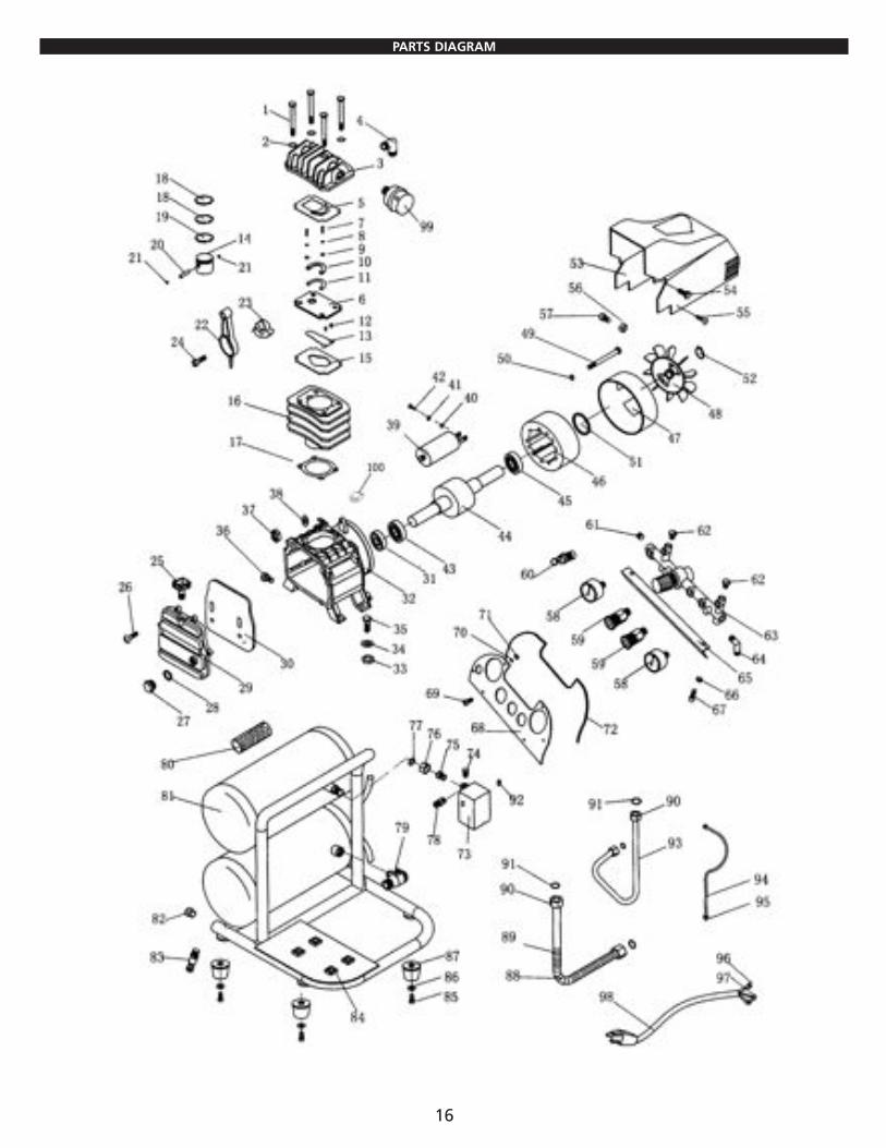
PARTS DIAGRAM
ONE YEAR LIMITED WARRANTY
ALLTRADE TOOLS LLC AIR COMPRESSORS
Express and Exclusive Limited Warranty to Original Retail Buyer
Alltrade Tools LLC (hereinafter “Alltrade”) expressly warrants to the original retail purchaser of the accompanying air compressor and no oneelse all parts of the product (except those parts referred to below which are specifically excluded from such warranty (see Exclusions) ) to be freefrom defects in materials and workmanship during the following periods from the original date of purchase:
For one (1) year from the date of purchase:• Compressor Pump• Plumbing• Tank assembly
For six (6) months from date of original purchase:• Pressure Switch• Pilot Valve• Copper/Stainless Steel Line• Regulator• Check Valve
For ninety (90) days from the original date of purchase: • Pressure Gauge• Drain Valve• Safety Release Valves• Quick Couplers
For thirty (30) days from the original date of purchase:• Air Accessories
The date of purchase shall be the date of shipment to the original purchaser, or the date the original purchaser took possession, custody orcontrol of the product, whichever occurred first. This warranty shall be null and void if the product or any component thereof is modified oraltered. This warranty does not apply to any other product and/or component thereof manufactured or distributed by Alltrade, and does notapply to products and/or components thereof designed, manufactured and/or assembled by others, for which Alltrade makes no warrantieswhatsoever. THERE ARE NO WARRANTIES WHICH EXTEND BEYOND THE DESCRIPTION ON THE FACE HEREOF.
Warranty Performance By purchasing the product, purchaser expressly acknowledges and agrees that their sole and exclusive remedy under this warranty shall bestrictly limited to the repair or replacement of any covered nonconforming items or parts thereof provided that any such nonconforming itemand/or part is promptly returned to Alltrade’s facility postage pre-paid and insured (ADDRESS: ALLTRADE Warranty Claims & Repair, 1431 ViaPlata, Long Beach, CA 90810, Attn: Customer Service (TELEPHONE: (800) 522-9008) ) within the applicable warranty period, with a writtenrequest by purchaser that Alltrade repair and/or replace the nonconforming item and/or part. We recommend that you keep the originalproduct packaging in the event you need to ship the unit. We suggest the package be insured against loss or in transit damage. When sendingyour product include your name, address, phone number, dated proof of purchase (or copy), and a statement about the nature of problem.Warranty coverage is conditioned upon purchaser furnishing Alltrade with adequate written proof that they are the original purchaser and ofthe original purchase date. Parts returned, freight prepaid and insured, to Alltrade’s facility (see above address) will be inspected and, atAlltrade’s option, repaired and/or replaced free of charge if found to be defective and subject to warranty. Alltrade retains the sole discretion todetermine whether any item or part is nonconforming and, if so, whether the item and/or part will be repaired and/or replaced. If Alltradechooses to replace the product, it may replace it with a new or reconditioned one of the same or comparable design. The repaired or replacedunit will be warranted under the terms of the remainder of applicable warranty period(s). Typically, covered defective parts not subject to normalwear and tear or other exclusions will be repaired or replaced, at Alltrade’s option, during the above stated warranty periods. Alltrade’s repairand/or replacement of any nonconforming item and/or part thereof shall constitute fulfillment of all obligations to the purchaser. Alltrade shallnot be responsible or liable for any expense, including freight charges, or repairs made outside Alltrade’s facility, unless expressly agreed to byAlltrade in writing. Under no circumstances shall Alltrade bear any responsibility for loss of the unit, loss of time or rental, inconvenience,commercial loss or consequential damages.
ExclusionsThis warranty does not cover parts damaged due to normal wear, abnormal conditions, misapplication, misuse, abuse, accidents, operation atother than recommended pressures or temperatures, improper storage or freight damage. Parts damaged or worn by operation in dustyenvironments are not warranted. Failure to follow recommended operating and maintenance procedures also voids warranty.
The following additional items are not covered under this warranty: pump or valve failure caused by rain, excessive humidity, corrosiveenvironments or other contaminants; cosmetic defects that do not interfere with compressor functionality; and rusted tanks, including but notlimited to rust due to improper drainage or corrosive environments.
This warranty shall not apply when: the air compressor has been used for commercial or rental purposes; defects in materials or workmanshipor damages result from repairs or alterations which have been made or attempted by others or the unauthorized use of nonconforming parts;damage is due to abuse (including overloading of the air compressor beyond capacity), improper maintenance, neglect or accident, or thedamage is due to use of the air compressor after partial failure or use with improper accessories.
17
Alltrade will not be liable for the following: labor charges, loss or damage resulting from improper operation, maintenance or repairs made byother persons; pre-delivery services such as assembly, oil or lubricants, and adjustment; maintenance services that are normally required tomaintain the air compressor.
The use of other than genuine Alltrade Repair Parts will void warranty.
Warranty Disclaimers EXCLUSION AND DISCLAIMER OF ALL OTHER EXPRESS WARRANTIES, GUARANTIES AND/OR REPRESENTATIONS. EXCEPT FOR THE LIMITEDWARRANTY PROVIDED ABOVE, ALL OTHER EXPRESS WARRANTIES, GUARANTIES AND/OR REPRESENTATIONS BY ALLTRADE AND/OR ITSREPRESENTATIVE(S) REGARDING THE DESIGN, MANUFACTURE, PURCHASE, USE AND/OR OPERATION OF THE AIR COMPRESSOR OR ANYCOMPONENT THEREOF SOLD HEREUNDER, REGARDLESS OF WHETHER ANY SUCH WARRANTY, GUARANTY AND/OR REPRESENTATION,WRITTEN OR ORAL, ARISES BY OPERATION OF LAW AND/OR EQUITY AND/OR BY ANY ACT OR OMISSION OF ALLTRADE AND/OR ITSREPRESENTATIVE(S), OR THE BUYER, ARE HEREBY EXPRESSLY EXCLUDED AND DISCLAIMED BY ALLTRADE AND/OR ITS REPRESENTATIVES.PURCHASER KNOWINGLY AND WILLINGLY WAIVES ANY AND ALL SUCH WARRANTIES AND RIGHTS, CLAIMS AND/OR CAUSES OF ACTIONARISING THEREFROM OR BASED THEREON. PURCHASER’S SOLE AND EXCLUSIVE REMEDY IS AS STATED ABOVE.
EXCLUSION AND DISCLAIMER OF ALL IMPLIED WARRANTIES, INCLUDING THE IMPLIED WARRANTIES OF MERCHANTABILITY AND FITNESS FORA PARTICULAR PURPOSE. NO WARRANTY, ORAL OR WRITTEN, OTHER THAN THE ABOVE WARRANTY IS MADE WITH REGARD TO THIS AIRCOMPRESSOR. ALL EXPRESS AND/OR IMPLIED WARRANTIES, GUARANTIES AND/OR REPRESENTATIONS BY ALLTRADE AND/OR ITSREPRESENTATIVE(S) REGARDING THE DESIGN, MANUFACTURE, PURCHASE, USE AND/OR OPERATION OF THE AIR COMPRESSOR OR ANYCOMPONENT THEREOF SOLD HEREUNDER, REGARDLESS OF WHETHER ANY SUCH WARRANTY, GUARANTY AND/OR REPRESENTATION,WRITTEN OR ORAL, ARISES BY OPERATION OF LAW AND/OR EQUITY AND/OR BY ANY ACT OR OMISSION OF ALLTRADE AND/OR ITSREPRESENTATIVE(S), OR THE PURCHASER, INCLUDING BUT NOT LIMITED TO THE IMPLIED WARRANTY OF MERCHANTABILITY AND THEWARRANTY OF FITNESS FOR A PARTICULAR PURPOSE, ARE HEREBY EXPRESSLY EXCLUDED AND DISCLAIMED BY ALLTRADE AND/OR ITSREPRESENTATIVES. PURCHASER KNOWINGLY AND WILLINGLY WAIVES ANY AND ALL SUCH WARRANTIES AND RIGHTS, CLAIMS AND/ORCAUSES OF ACTION ARISING THEREFROM OR BASED THEREON.
PURCHASER’S SOLE AND EXCLUSIVE REMEDY IS AS STATED ABOVE.
Limitation Of LiabilityIN NO EVENT SHALL ALLTRADE AND/OR ITS REPRESENTATIVE(S) BE LIABLE FOR INDIRECT, INCIDENTAL, SPECIAL AND/OR CONSEQUENTIALDAMAGES OF ANY KIND ARISING OUT OF OR RELATED TO, DIRECTLY OR INDIRECTLY, ANY BREACH OF ANY PROVISION OF ANY AGREEMENTBETWEEN ALLTRADE AND/OR ITS REPRESENTATIVE(S) AND PURCHASER, ANY WARRANTY HEREUNDER, AND/OR THE EXISTENCE, DESIGN,MANUFACTURE, PURCHASE, USE AND/OR OPERATION OF ANY ITEM(S) SOLD HEREUNDER EVEN IF ALLTRADE AND/OR ITS REPRESENTATIVE(S)HAS BEEN ADVISED OF THE POSSIBILITY OF ANY SUCH DAMAGES. IN NO EVENT, WHETHER AS A RESULT OF A BREACH OF CONTRACT,WARRANTY, TORT (INCLUDING NEGLIGENCE) OR OTHERWISE, SHALL ALLTRADE’S AND/OR ITS REPRESENTATIVE(S)’ LIABILITY EXCEED THEPRICE OF THE AIR COMPRESSOR. ANY AND ALL LIABILITY CONNECTED WITH THE USE OF THIS AIR COMPRESSOR SHALL TERMINATE UPONTHE EXPIRATION OF THE WARRANTY PERIODS SPECIFIED ABOVE.
Limitations on Warranty Disclaimers Some states do not allow limitations on how long an implied warranty lasts and some states do not allow the exclusion or limitation of theincidental or consequential damages, so part or all of the above limitations or exclusions may not apply to you. This warranty gives you specificlegal rights, and you may also have other rights which vary from state to state.
If your product is not covered by this warranty, please call our Customer Service Department at (800) 423-3598 for general repair informationand charges.
18

WEAR SAFETY GLASSES
WARNING
1431 Via Plata
Long Beach, CA 90810-1462 USA
Made in: China
©2006 REV.1, Alltrade Tools LLC
www.alltradetools.com
HOT ROD Magazine is a trademark of PRIMEDIA SpecialtyGroup, Inc. and is used with permission. © 2006PRIMEDIA Specialty Group, Inc. All rights reserved. www.hotrod.com