powerlift m20c operator's manual 2015
DESCRIPTION
ÂTRANSCRIPT

OPERATOR’S SAFETY MANUAL
www.reechcraft.com/powerlift
P/N 4026370
M20C

PowerLift by ReechCraft2
It is very important that you read, understand and obey the contents of this manual! Keep it with the machine at all times.
The purpose of this manual is to provide safe and proper operating procedures for anyone utilizing the benefits of this machine.
Because we at Reechcraft, Inc. are always working to improve our products, processes and procedures, we reserve the right to make changes without prior notice. Please contact us at Reechcraft for updated information.
This is the Safety Alert Symbol. It is used throughout this manual and on the machine to alert you to potential personal injury hazards. Understand and obey all safety messages that correspond with this symbol to avoid possible injury or death.
INDICATES AN IMMINENTLY HAZARDOUS SITUATION AND IF NOT AVOIDED WILL RESULT IN SERIOUS INJURY OR DEATH. THIS DECAL WILL HAVE A RED BACKGROUND.
INDICATES A POTENTIALLY HAZARDOUS SITUATION. IF NOT AVOIDED, COULD RESULT IN SERIOUS INJURY OR DEATH. THIS DECAL WILL HAVE AN ORANGE BACKGROUND.
INDICATES A POTENTIALLY HAZARDOUS SITUATION THAT IF NOT AVOIDED, MAY RESULT IN MINOR OR MODERATE INJURY. IT MAY ALSO ALERT AGAINST UNSAFE PRACTICES. THIS DECAL WILL HAVE A YELLOW BACKGROUND.
DANGER
NOTICE
CAUTION
WARNING
DANGER
NOTICE
CAUTION
WARNINGDANGER
NOTICE
CAUTION
WARNINGDANGER
NOTICE
CAUTION
WARNING
SAFETY ALERT SYMBOLS AND SAFETY SIGNAL WORDS
www.reechcraft.com/powerlift

www.reechcraft.com/powerlift 888-600-6160 3
THIS PRODUCT MUST COMPLY WITH ALL SAFETY RELATED BULLETINS. CONTACT REECHCRAFT, INC. OR THE LOCAL AUTHORIZED REECHCRAFT REPRESENTIVE FOR INFORMATION REGARDING SAFETY RELATED BULLETINS WHICH MAY HAVE BEEN ISSUED FOR THIS PRODUCT.
REECHCRAFT, INC. SENDS SAFETY RELATED BULLETINS TO THE OWNER OF RECORD OF THIS MACHINE. CONTACT REECHCRAFT TO ENSURE THAT THE CURRENT OWNER RECORDS ARE UPDATED AND ACCURATE.
REECHCRAFT MUST BE NOTIFIED IMMEDIATELY IN ALL INSTANCES WHERE OUR PRODUCTS HAVE BEEN INVOLVED IN AN ACCIDENT INVOLVING BODILY INJURY OR DEATH OF PERSONNEL OR WHERE SUBSTANTIAL PERSONAL PROPERTY DAMAGE OR DAMAGE TO THE REECHCRAFT PRODUCT HAS OCCURRED.
FORWARDDANGER
NOTICE
CAUTION
WARNINGDANGER
NOTICE
CAUTION
WARNING
DANGER
NOTICE
CAUTION
WARNING
FOR:• Accident Reporting
• Product Safety Publications
• Current Owner Updates
• Product Safety Questions
• Standards and Regulations Compliance Information
• Questions Regarding Special Applications
• Questions Regarding Product Modifications
CONTACT:
Technical Safety and Engineering Department 474 45th Street South Fargo, ND 58103
In USAToll Free: 888-600-6160E-mail: [email protected]
Outside USAPhone: 701-280-5900

PowerLift by ReechCraft4
REVISION LOGOriginal issue of Manual....................................... ..........................April 2, 2014
TABLE OF CONTENTSSECTION - INFORMATIONAL
FOREWORD ........................................................................................................ 2SAFETY ALERT SYMBOLS AND SAFETY WORDS ....................................... 2-3CONTACT ........................................................................................................... 3REVISION LOG ................................................................................................... 4
SECTION - 1 - SAFETY PRECAUTIONS ............................................................ 8
1.1 GENERAL .................................................................................................... 8 1.2 PRE-OPERATION ........................................................................................ 8 Operator Preparedness ................................................................... 8 Work Site Inspection ........................................................................ 9 Machine Inspection .......................................................................... 9 1.3 OPERATION ...............................................................................................10 General ............................................................................................10 Fall Hazards .....................................................................................10 Electrocution Hazard ......................................................................11 Tipping Hazards ............................................................................. 12 Crushing and Collisions Hazards ...................................................14 1.4 MANEUVERING, TRANSPORTING AND LIFTING .................................. 15 General ........................................................................................... 15 Additional Safety Information ...................................................... 15
SECTION - 2 - PREPARATION AND INSPECTION .......................................... 16
2.1 PERSONNEL REQUIREMENTS ............................................................... 16 Operator Requirements ................................................................. 16 Operator Responsibilities .............................................................. 16 2.2 PREPARATION, INSPECTION AND MAINTENANCE ............................. 17 Pre-Start Inspection ....................................................................... 17 2.3 DAILY WALK-AROUND INSPECTION ..................................................... 18 Walk-Around Inspection Components ..........................................19 2.4 FUNCTION CHECK ................................................................................... 24 Function Check Items .................................................................... 24

www.reechcraft.com/powerlift 888-600-6160 5
SECTION - 3 - MACHINE OPERATION ............................................................ 26
3.1 GENERAL .................................................................................................. 263.2 MACHINE DESCRIPTION ......................................................................... 26 Drill Motor ...................................................................................... 283.3 MACHINE OPERATION ............................................................................ 29 General3.4 MACHINE SET UP .................................................................................... 30 Getting Started ............................................................................... 30 Elevating ......................................................................................... 31 Joining Mast Sections ................................................................... 32 Separating Mast Sections ............................................................. 33 Unpowered Descent ...................................................................... 333.5 MANEUVERING AND TRANSPORT ........................................................ 34 General ........................................................................................... 34 Upright Maneuvering .................................................................... 34 Tilted Over Maneuvering .............................................................. 34 Parking and Storage ...................................................................... 36 Vehicle Transport ............................................................................ 36
SECTION - 4 - EMERGENCY PROCEDURES .................................................. 37
4.1 GENERAL INFORMATION ....................................................................... 37 Manual Descent Crank .................................................................. 37 Discharged Battery or Loss Of Power .......................................... 38 Operator Unable To Control Machine ........................................... 39 Platform Caught Overhead ........................................................... 404.2 INCIDENT NOTIFICATION ....................................................................... 40
SECTION - 5 - GENERAL SPECIFICATIONS ................................................... 41
5.1 INTRODUCTION ....................................................................................... 415.2 DECAL CONTENTS AND LOCATION ................................................. 41-445.3 SPECIFICATIONS ..................................................................................... 45 Machine Specifications ................................................................. 45
TABLE OF CONTENTS

PowerLift by ReechCraft6
SECTION - 6 - SERVICE AND MAINTENANCE ............................................... 47
6.1 MAINTENANCE SAFETY PRECAUTIONS .............................................. 47 General ........................................................................................... 47 Maintenance Safety ....................................................................... 486.2 MACHINE PREPARATION, INSPECTION AND MAINTENANCE ........... 49 General ........................................................................................... 49 Preparation, Inspection and Maintenance ................................... 49 Pre-Start Inspection ....................................................................... 49 Frequent and Pre-Delivery Inspection .......................................... 49 Annual Machine Inspection .......................................................... 50 5 year Inspection and Track Replacement .................................... 506.3 PREVENTIVE MAINTENANCE AND INSPECTION SCHEDULE ............. 51 Inspection and Maintenance Codes ............................................. 516.4 SERVICING AND MAINTENANCE GUIDELINES .................................... 53 General ........................................................................................... 53 Safety and Workmanship .............................................................. 53 Cleanliness ..................................................................................... 53 Component Disassembly and Reassembly ................................. 536.5 DECAL REPLACEMENT ........................................................................... 546.6 MAST TRACK INSPECTION PROCEDURE .............................................. 54 Mast Track Wear .............................................................................. 55 Mast Track Misalignment .............................................................. 55 Mast Connector Wear .................................................................... 55
SECTION - 7 - TROUBLESHOOTING ............................................................... 56
7.1 GENERAL .................................................................................................... 56 Troubleshooting Information .................................................................. 56
TABLE OF CONTENTS

www.reechcraft.com/powerlift 888-600-6160 7
LIST OF FIGURES1-1. Read your manual ...........................................................................................8
2-1. Inspection Points ...........................................................................................19
2-2. Chassis/Bubble Level ...................................................................................20
2-3. Climbing Unit ................................................................................................21
2-4. Maximum Track Wear ...................................................................................22
2-5. Location of Manual Descent Crank .............................................................22
2-6. Location of Emergency Retraction System ................................................23
2-7. Platform Mounting and Retaining Pins .......................................................24
2-8. Mast Connectors ..........................................................................................25
3-1. Fully Stowed Machine ............................................................................ 26-27
3-2. Typical Drill Motor .........................................................................................28
3-3. Proper Set Up................................................................................................30
3-4. Bubble Level .................................................................................................31
3-5. Drill Motor Operation/Elevating ..................................................................31
3-6. Joining Mast Sections ..................................................................................32
3-7. Separating Mast Sections .............................................................................33
3-8. Maneuvering When Tilted Back ...................................................................35
4-1. Manual Descent Crank Operation................................................................38
4-2. Emergency Retraction System ....................................................................39
5-1. Chassis/Base Mast Decal Locations ............................................................42
5-2. Climbing Unit Decal Locations ....................................................................42
5-3. Platform Decal Locations .............................................................................43
5-4. Outrigger Decal Locations ...........................................................................44
5-5. Machine Specifications ................................................................................46
6-1. Mast/Track Alignment ...................................................................................55
LIST OF TABLES1-1. Minimum Approach Distances (M.A.D) ....................................................... 11
2-1. Inspection and Maintenance ........................................................................18
5-1. Decal Contents and Location .......................................................................41
5-2. Machine Specifications ................................................................................45
6-1. Preventive Maintenance and Inspection Schedule ....................................52
7-1. Troubleshooting Guide ..................................................................................57
TABLE OF CONTENTS

PowerLift by ReechCraft8
This section is the starting point for establishing habitual precautions for safe operation of the machine. This manual is your guide in developing a daily routine that focuses on safety and proper maintenance of the machine prior to each use. A maintenance program must be established and conducted by a qualified person to ensure the machine is in safe working condition before it is operated.
Before operating the machine, the operator shall:
1. Read, understand and obey the operating instructions and safety rules in this manual.
2. Obey all labels, warnings and instructions located on the machine.
3. Be sure that all occupants of the machine wear appropriate personal protection equipment (PPE) for the conditions.
If there are any questions regarding safety, training, maintenance, inspection, application or operation of the machine, please contact Reechcraft.
FAILURE TO COMPLY WITH THE SAFETY PRECAUTIONS LISTED IN THIS MANUAL COULD RESULT IN MACHINE DAMAGE, PROPERTY DAMAGE, PERSONAL INJURY OR DEATH.
1.1 General
DANGER
NOTICE
CAUTION
WARNING
SECTION 1SAFETY PRECAUTIONS
Operator Preparedness
• Do not operate this machine until the operator has read and fully comprehends the Operator’s Safety Manual of the machine.
• Only competent personnel may operate the machine.
• Read, fully comprehend and obey all DANGERS, WARNINGS, CAUTIONS and operating instructions on the machine and in this manual.
• Only use this machine in a manner which is within the scope of the intended application set by Reechcraft.
1.2 Pre-OperationFigure 1-1 Read your manual

www.reechcraft.com/powerlift 888-600-6160 9
• All operating personnel must be familiar with the emergency
procedures and controls specified in this manual
• All operating personnel must read, comprehend and obey all applicable employer, local and governmental regulations as they pertain to the safe operation of the machine.
Work Site Inspection
• The operator is to take measures to identify and avoid all hazards in the work area that will affect the safe operation of the machine.
• Do not elevate unless all tools, equipment and materials can be safely stowed within the platform.
• Machine can be operated in ambient air temperature of -20°F to 135°F (-29°C to 57°C). Consult Reechcraft for operation outside of this range. Machine performance may be affected in very hot or cold conditions.
Machine Inspection
• Before machine operation, perform walk around inspections and function checks. Refer to Section 2 of this manual for further instructions.
• No one shall operate the machine until it has been inspected, serviced and maintained according to the requirements in this manual.
MODIFICATION OR ALTERATION OF MACHINE SHALL BE MADE ONLY WITH PRIOR WRITTEN PERMISSION FROM THE MANUFACTURER
• Do not operate any machine on which the safety decals or instruction placards are missing or illegible.
• Avoid any build up of debris on platform floor. Keep mud, oil, grease and other slippery substances from footwear and the platform floor.
SECTION 1SAFETY PRECAUTIONS
DANGER
NOTICE
CAUTION
WARNING

PowerLift by ReechCraft10
1.3 Operation
General
• Do not use the machine for any purpose other than positioning personnel, their tools, equipment and materials.
• Never operate a machine that is not working properly. If a malfunction occurs, shut down the machine and contact Reechcraft.
• Unless in an emergency, do not allow personnel to tamper with, or operate the machine from the ground with personnel on the platform.
• The operator will not elevate the platform unless the bearing surface is stationary and capable of supporting the intended load.
• Always ensure that power tools are properly stowed and never left suspended by their cord from the platform.
• Be sure to fully lower the platform to the docked position and shut off all power before leaving the machine.
• No more than one person is allowed on the machine. Only the operator is permitted in the platform during operation.
Fall Hazards
• Do not enter or leave the platform while elevated.
• Before operating the machine, make sure all mast sections, outriggers, railings and gates are in their proper position. Be sure the platform is properly secured to the climbing unit before operating the machine.
• Keep both feet firmly positioned on the platform floor at all times. Never use ladders, boxes, steps, planks or any other item on the platform to provide additional height for greater reach.
• Never use the mast or railings to enter or leave the platform.
SECT
ION
1 SAFETY PRECAUTIONS

www.reechcraft.com/powerlift 888-600-6160 11
SECTION 1SAFETY PRECAUTIONS
• Always use extreme caution when entering or exiting the platform. Be sure that the platform is fully lowered in the docked position before exiting the platform.
• Always maintain three points of contact with the machine. “3 point contact” means using two hands and one foot or two feet and one hand at all times while entering or exiting the platform.
Electrocution Hazard
• This machine is not insulated and will not provide protection from contact or proximity to electrical current.
• Maintain distance from electrical lines, apparatus or any energized (exposed or insulated) parts according to the Minimum Approach Distance (MAD) as shown in Table 1-1.
• Allow clearance for machine movement and electrical line swaying.
Table 1-1 Minimum Approach Distances (M.A.D.)
VOLTAGE RANGE(PHASE TO PHASE)
MINIMUM SAFE APPROACHDISTANCE - FEET (METERS)
0-50KV 10 (3)
Over 50KV to 200KV 15 (5)
Over 200KV to 350KV 20 (6)
Over 350KV to 500KV 25 (8)
Over 500KV to 750KV 35 (11)
Over 750KV to 1000KV 45 (14)
NOTE: This requirement shall apply except where employer, local or governmental regulations are more stringent.

PowerLift by ReechCraft12
• Maintain a clearance of at least 10 ft. (3m) between any part of the machine and its occupants, their tools and their equipment from any electrical line or apparatus carrying up to 50,000 volts. One foot (0.3m) additional clearance is required for every additional 30,000 volts or less.
• The minimum safe approach distance may be reduced if insulating barriers are installed to prevent contact, and if the barriers are rated for the voltage of the line being guarded. These barriers shall not be part of (or attached to) the machine. The minimum safe approach distance shall be reduced to a distance within the designed working dimensions of the insulating barrier. This determination shall be made by a qualified person in accordance with employer, local or governmental requirements for work practices near energized equipment.
DO NOT MANEUVER MACHINE OR PERSONNEL INSIDE PROHIBITED ZONE (MAD). ASSUME ALL ELECTRICAL PARTS AND WIRING ARE ENERGIZED UNLESS KNOWN OTHERWISE.
Tipping Hazards
• Be sure the bearing surface is solid, stationary and capable of supporting the intended load.
• Before entering the platform, ensure that all outriggers have been properly installed and all leveling jacks are fully extended and bearing weight.
• Check to be sure the chassis is level according to the bubble level indicator on the chassis and all wheels are completely off the ground. Note: the platform will not release from its docked position unless each outrigger is in its proper position, fully extended and bearing weight.
SECT
ION
1 SAFETY PRECAUTIONS
DANGER
NOTICE
CAUTION
WARNING

www.reechcraft.com/powerlift 888-600-6160 13
SECTION 1SAFETY PRECAUTIONS
• Do not perform work that will subject the machine to a horizontal force or create a swaying motion of the platform.
• Do not elevate platform outdoors. This machine is intended for internal use only.
• The user should be familiar with the operating surface. If there is a question related to the stability of the ground condition, an appropriate mud sill should be used to safely spread the load of the machine and rated load capacity.
• Do not elevate the platform on a slope greater than what can be leveled by the outrigger leveling jacks and an appropriate mud sill.
• Do not elevate if there is a safety concern related to the stability of the bearing surface.
• Before using the machine on floors, bridges, and other surfaces, check allowable capacity of the surfaces.
• Never exceed the maximum platform capacity. Distribute loads evenly on platform floor.
• Keep the bearing pads of the outriggers a safe distance from holes, bumps, drop-offs, obstructions, debris, concealed holes and other potential hazards at the ground level.
• Never attempt to use the machine as a crane. Do not tie off machine to any adjacent structure.
• Do not increase the platform size with unauthorized extensions or attachments as increasing the area exposed to personnel movement will decrease stability.
• If the mast or platform is caught so that one or more of the outrigger bearing pads are off the ground, the operator must be removed before attempting to free the machine. Use cranes, forklift trucks or other appropriate equipment to stabilize the machine and remove personnel.

PowerLift by ReechCraft14
Crushing and Collision Hazards
• Appropriate personal protection equipment must be worn by all operating and ground personnel.
• Check work area clearances above, on sides and below platform while moving, elevating or lowering platform.
• Be sure to keep all body parts inside the platform railing during operation.
• Exercise extreme caution at all times to prevent obstacles from striking or interfering with operating controls (drill) and persons in the platform.
• Ensure that operators of other overhead and floor level equipment or machines are aware of the machines presence. Disconnect power to overhead cranes.
• Warn personnel not to work, stand or walk under an elevated platform. Position barricades on the floor as necessary.
SECT
ION
1 SAFETY PRECAUTIONS

www.reechcraft.com/powerlift 888-600-6160 15
SECTION 1SAFETY PRECAUTIONS
1.4 Maneuvering, Transporting & Lifting
General
• Never allow personnel in the platform while moving, lifting or repositioning the machine.
• This machine shall not be towed by a vehicle.
• Be sure the platform is fully lowered and outriggers and mast sections are properly stowed before tilting back for rough terrain transport.
• Remove drill, tools and equipment from platform when transporting in a vehicle.
• Refer to the Machine Operation section of this manual for lifting information.
Additional Safety Information
• Platform must be fully lowered before outriggers can be safely removed.
• Do not use machine as a ground for welding.
• Do not attempt to transport assembled machine by forklift.
• Be sure to lock two or more of the casters before leaving the machine unattended.
• Use extreme caution when transporting the machine on a slope in the upright position.

PowerLift by ReechCraft16
2.1 Personnel RequirementsThis Machine is intended to be used as a personnel handling device and must be operated and maintained by competent personnel only.
Anyone under the influence of drugs, alcohol or are subjected to bouts of dizziness, seizures or loss of physical control must not operate this machine.
Operator Requirements
Before operating this machine, the operator must read and comprehend this manual.
The operator must be familiar with:
1. Use and limitations of the components of the machine including the specification requirements of the drill motor.
2. Instruction placards and warning decals on the machine and in this manual.
3. Employer and government regulations.
4. Use of approved fall protection device (where applicable).
5. Sufficient mechanical aptitude and knowledge of the machine to recognize a component malfunction or a potential malfunction.
6. The safest means to operate the machine where overhead and ground hazards are present. These hazards include: overhead obstructions, additional moving equipment, obstacles, depressions, drop-offs, etc.
7. A means to avoid unprotected electrical conductors.
8. The specific job requirements.
SECTION 2PREPARATION & INSPECTION
Operator ResponsibilitiesThe exercise of good judgment, safety control, and caution in evaluating each situation is the responsibility of the Operator. The Operator must shut down the machine in the event of a malfunction or other unsafe condition of the machine or job site.

www.reechcraft.com/powerlift 888-600-6160 17
2.2 Preparation, Inspection & Maintenance
SECTION 2PREPARATION & INSPECTION
Pre-Start Inspection
The Pre-Start Inspection should include each of the following:
1. Cleanliness - Check all surfaces for leakage, debris or foreign objects.
2. Decals and Placards - Check for cleanliness and legibility. Make sure none of the decals or placards are missing. Make sure all illegible decals are cleaned or replaced. (Reference Section 5.2 Decal Contents and Location)
3. Safety, Service - Make sure a copy of the Operator’s and Safety manual is enclosed in a weather resistant container.
4. Set-Up - Make sure the machine is set-up in accordance with Section 3.4.
5. Walk-Around Inspection - Refer to Section 2.3.
6. Drill Selection Criteria - Refer to Section 3.2.
7. Function Check - Once the Walk-Around Inspection is complete, perform a function check of all systems in an area free of all over-head or ground level obstructions. Refer to Section 2.4 for additional information.

PowerLift by ReechCraft18
SECT
ION
2 PREPARATION & INSPECTION
Begin the Daily Walk-Around Inspection starting at item one (1) as noted on the diagram Figure 2-1. Continue around the machine checking each item in sequence for the conditions listed in the following check list.
TO AVOID POSSIBLE INJURY MAKE SURE THERE IS NO POWER SUPPLIED TO THE MACHINE DURING THE WALK AROUND INSPECTION DO NOT OPERATE MACHINE UNTIL ALL MALFUNCIONS HAVE BEEN CORRECTED.
2.3 Daily Walk-Around Inspection
DANGER
NOTICE
CAUTION
WARNING
The following table outlines the periodic machine inspection and maintenance recommended by Reechcraft. Consult local regulations for further requirements.
The frequency of inspections and required maintenance must be increased if the machine is exposed to harsh conditions, increased use or if the machine is used in a severe manner.
Table 2-1 Inspection and Maintenance
TYPE FREQUENCYPRIMARY
RESPONSIBILITYSERVICE
QUALIFICATION REFERENCE
Pre-startInspection
Before starting each day or at shift change Operator User or Operator Operator’s and
Safety Manual
Frequent Inspection
In service or out of service for 3 mo. Or
purchased used
Owner, Dealer or User
Qualified Mechanic*
Operator’s and Safety Manual
Annual Machine
InspectionEvery 12 Months Owner, Dealer or
UserQualified
Mechanic*Operator’s and Safety Manual
Replacement When Track is worn or damaged
Owner, Dealer or User
Qualified Mechanic*
Operator’s and Safety Manual
NOTE: Use this manual to perform inspections
NOTE: *A person who has acquired training, qualifications or a combination of these, the knowledge and skill enabling the person to inspect and repair the machine to the level required by the complexity of the task.

www.reechcraft.com/powerlift 888-600-6160 19
SECTION 2PREPARATION & INSPECTION
NOTE: Do not overlook the underside of the chassis. Check this area for corrosion, debris and cracks.
NOTE: The Mast and Climbing Unit should be clean and free of grease, oil and dirt. Do not lubricate the Mast or Climbing Unit components.
Walk-Around Inspection Components
Figure 2-1 - Inspection Points
10
1
5
2
3
4
6
8
9
7

PowerLift by ReechCraft20
SECT
ION
2 PREPARATION & INSPECTION
NOTE: On all components, make sure there are no loose or missing parts and that everything is securely fastened. Make sure that there is no visible damage or excessive wear.
1. Rear Wheels - Check for any debris stuck to or around the wheel or axle. Make sure the axle bolts are tight and that the wheel spins freely.
2. Chassis - Check for cracks or corrosion especially at intersecting weld joints. Make sure Bubble Level is clean and functioning. (See Figure 2-2)
3. Mast Sections - Check for cracks and corrosion. Make sure the Cam Levers are not bent or misshapen and springs are functioning properly. Make sure the track teeth are not worn, bent or misshapen. Make sure the Cam Lever Lock is not bent or misshapen and the spring is functioning properly. Make sure the Connector Pins are not worn or damaged and the Connector Pin Openings are clean and free of debris. Check to be sure the Cam Lever Shaft is not showing excessive wear. (See Figures 2-1, 6-1 and 2-4)
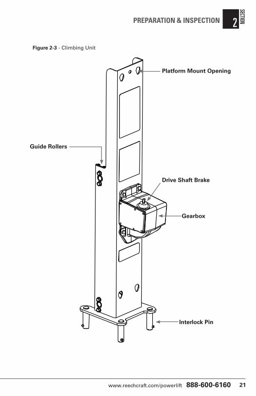
4. Climbing Unit - Check for visible cracks or corrosion. Check guide rollers for visible wear and proper alignment. Check to be sure all fasteners and interlock pins are tight and functioning properly. (See Figure 2-3)
Fig 2-2 - Bubble Level
www.reechcraft.com/powerlift 888-600-6160 21
SECTION 2PREPARATION & INSPECTION
Figure 2-3 - Climbing Unit
Guide Rollers
Platform Mount Opening
Drive Shaft Brake
Gearbox
Interlock Pin

PowerLift by ReechCraft22
5. Gearbox - Check for any oil leaks and make sure the Drive Shaft Brake is functioning properly by pressing down on the hex shaft. The hex shaft should return to the up position freely without excessive side movement.
6. Swivel Casters - Check for any debris stuck to or around the wheels or swivel mechanism. Check to be sure the lock is in good working condition and that the wheels are functioning properly.
7. Track Sections - Check that the teeth of all the track sections are not excessively worn(.1875” tooth remaining), bent, misshapen or missing. (See Figure 2.4)
SECT
ION
2 PREPARATION & INSPECTION
Figure 2-4 - Maximum Track Wear
Figure 2-5 - Location of Manual Decent Crank
.188”
Manual Descent Crank

www.reechcraft.com/powerlift 888-600-6160 23
SECTION 2PREPARATION & INSPECTION
8. Manual Decent Crank - Check to be sure it is present and securely attached (See Fig. 2.5)
9. Emergency Retraction System - Check to be sure the two components of the retrieval system are present and in good working order; Retraction Winch present, secure, and free of foreign material; Retraction Strap Tool present and secure. (See Fig. 2.6)
10. Platform and Entry Gate - Check to be sure that the mounting pins are not loose; platform railing is undamaged; platform retaining pin is functioning properly; self closing slide gates are functioning properly; no cracks or visible corrosion present. (See Fig. 2.7)
Figure 2-6 - Location of Emergency Retraction System
Retraction Winch
Retraction Strap Tool

PowerLift by ReechCraft24
Once the Walk-Around Inspection check is complete, perform a function check of all systems in an area free of overhead and ground level obstructions.
IF THE MACHINE DOES NOT OPERATE PROPERLY, SHUT OFF AND REMOVE POWER FROM THE MACHINE IMMEDIATELY! REPORT THE PROBLEM TO THE PROPER MAINTENANCE PERSONNEL AND DO NOT OPERATE THE MACHINE UNTIL IT HAS BEEN DEEMED SAFE FOR OPERATION.
Function Check Items
1. Drive Shaft Brake - Check to be sure the input hex shaft plunges properly and returns to it’s properly seated position. The input hex shaft should be firmly seated in its return position and resist turning freely in either direction. (See Figure 2-7)
SECT
ION
2 PREPARATION & INSPECTION
2.4 Function Check
DANGER
NOTICE
CAUTION
WARNING
Figure 2-7 - Platform Mounting and Retaining Pins
Mount Pin Openings
Mount Pin Openings
Mount Pins
Mount Pins
Input Hex Shaft
Entry Gate
PlatformRetainingPin
Entry Gate

www.reechcraft.com/powerlift 888-600-6160 25
SECTION 2PREPARATION & INSPECTION
2. Overload Clutch - Check to be sure the Overload Clutch is functioning properly by briefly running the drill motor in the reverse direction (counterclockwise). You should hear and audible buzzing sound. NOTE: Be sure to maintain a firm grip on the drill.
3. Outrigger Interlock - Check to be sure the Outrigger Interlock is functioning properly by briefly running the drill motor in the forward position (clockwise) with the outriggers removed. The platform should not disengage from its docked position and you should hear an audible “buzzing” sound coming from the overload clutch slipping. NOTE: Be sure to maintain a firm grip on the drill.
4. Mast Connectors - Check to be sure the components of the Mast Connectors are present, undamaged, clear of debris and in good working condition. (See Fig. 2.8) NOTE: Be sure the top mast Termination Plate is present, undamaged and securely attached to the mast section.
Figure 2.8 - Mast Connectors
Mount Pins
Cam Lever
Connector Pin Opening
Connector Pins
Cam LeverLock
Top Termination Plate

PowerLift by ReechCraft26
3.1 GeneralNOTE: The manufacturer has no direct control over the machine application and operation. The operator is responsible for following sound safety practices.
3.2 Machine DescriptionThe Reechcraft PowerLift is a drill powered aerial work platform (AWP). The removable platform is mounted to an elevating climbing unit that combines up to four (4) modular mast sections that are stacked and fixed to a base mast on a movable chassis. The machine is stabilized by way of outriggers and leveling jacks. The PowerLift’s intended purpose is to provide personnel and their tools access to work areas above the ground.
SECTION 3MACHINE OPERATION
Figure 3- 1 Fully Stowed Machine (1 of 2)
1
12
2
3
4
5
6
7
8
9
10
5
5
24

www.reechcraft.com/powerlift 888-600-6160 27
SECTION 3MACHINE OPERATION
The primary control of the machine is the drill motor.
NOTE: Be sure to follow the recommended drill motor specifications for safe operation and best machine performance.
Figure 3- 1 Fully Stowed Machine (2 of 2)
1. Climbing Unit 2. Intermediate Mast 3. Drive Shaft Brake 4. Manual Container 5. Outrigger Socket 6. Manual Descent Crank 7. Platform 8. Gearbox 9. Platform Entry Gate 10. Platform Retaining Pin 11. Tilt-back handle 12. Horizontal Transport Wheel
13. Retraction Strap Tool 14. Top Mast 15. Front Outrigger 16. Leveling Jack 17. Rear Outrigger 18. Retraction Winch 19. All Terrain Transport Tire 20. Tilt-back Step 21. Outrigger Storage Socket 22. Bubble Level 23. Chassis 24. Anchor Point/Ext. Cord Throughway
11
13
14
15
16
17
18
19
20
21
22
23
24
12
19
5
9
Legend

PowerLift by ReechCraft28
SECT
ION
3 MACHINE OPERATION
Drill Motor
Reechcraft recommends a cordless drill of at lease 18V capacity or a corded drill of at least 7 amps.
Ensure the drill motor’s optional “Hammer” setting is disabled and the drill motor is in “Drill” mode.
Figure 3-2 - Typical Drill Motor
1. Chuck
2. Torque control (cordless drill option)
3. Power Trigger
4. Speed Controller (optional)
5. Drill/Hammer Function Selector (optional)
6. Direction Selector
7. Battery Pack (cordless) 8. Power Cord
USE ONLY CORDLESS OR DOUBLE INSULATED CORDED DRILL MOTORS. DISCONTINUE THE USE OF THE DRILL IF A FAULT IS DETECTED. ENSURE THE DRILL MOTOR IS IN “DRILL” MODE AND SET TO THE APPROPRIATE TORQUE SETTING.
DANGER
NOTICE
CAUTION
WARNING
1
23
4
5
6
7
8

www.reechcraft.com/powerlift 888-600-6160 29
SECTION 3MACHINE OPERATION
General
When the platform reaches the bottom of its travel and seats in the “Docked” position the overload clutch creates a ratcheting or buzzing noise, indicating that the machine has reached the fully lowered position.
BE SURE TO MAINTAIN A FIRM GRIP ON THE DRILL AT ALL TIMES DURING OPERATION.
The machine is fitted with a drive shaft brake to prevent motion of the platform not initiated by the operator.
Before operating the machine, be sure the platform is fully lowered and all four (4) outriggers are properly installed. Be sure the machine is level and on a surface capable of supporting the intended load.
IN THE EVENT THAT THE CLIMBING UNIT FAILS TO ELEVATE AFTER THE OUTRIGGERES HAVE BEEN PROPERLY INSTALLED AND STABLIZED, THE MACHINE IS NOT WORKING PROPERLY AND MUST NOT BE USED UNTIL IT IS INSPECTED AND REPAIRED BY A QUALIFIED PERSON.
NOTE: Do not attempt to enter or exit the platform unless it is fully lowered in the docked position.
3.3 Machine Operation
DANGER
NOTICE
CAUTION
WARNING
DANGER
NOTICE
CAUTION
WARNING

PowerLift by ReechCraft30
SECT
ION
3 MACHINE OPERATION
Because the Reechcraft PowerLift is a modular operator assembled machine, the platform, each outrigger and mast section can be removed to reduce weight as the situation requires.
NOTE: For the purposes of this section, it is assumed that the machine is in it’s fully stowed configuration.
Getting Started
1. Place the machine on a firm, stationary surface capable of supporting the intended load directly under the desired work area.
2. Connect to an appropriate power source. AC: connect to a grounded 15A AC power supply. Be careful the extension cord remains slack at maximum height and does not become entangled in the machine.
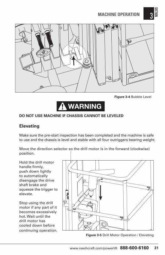
3. Install front and rear outriggers in their designated positions. Using the drill and 3/8” socket, level the chassis by adjusting each of the leveling jacks, until the level bubble is centered (Figure 3-4).
NOTE: For best performance, Reechcraft recommends a 12 gauge 3 wire extension cord no longer than 50 feet.
3.4 Machine Setup
Figure 3-3 Proper Set Up
www.reechcraft.com/powerlift 888-600-6160 31
SECTION 3MACHINE OPERATION
DO NOT USE MACHINE IF CHASSIS CANNOT BE LEVELED
Elevating
Make sure the pre-start inspection has been completed and the machine is safe to use and the chassis is level and stable with all four outriggers bearing weight.
Move the direction selector so the drill motor is in the forward (clockwise) position.
Hold the drill motor handle firmly, push down lightly to automatically disengage the drive shaft brake and squeeze the trigger to elevate.
Stop using the drill motor if any part of it becomes excessively hot. Wait until the drill motor has cooled down before continuing operation.
DANGER
NOTICE
CAUTION
WARNING
Figure 3-5 Drill Motor Operation / Elevating
Figure 3-4 Bubble Level

PowerLift by ReechCraft32
Joining Mast Sections
Elevate the climbing unit approximately 3 inches past the top of the mast and carefully remove the mast section from its stowed position.
SECT
ION
3 MACHINE OPERATION
Figure 3-6 Joining Mast Sections
DO NOT DROP MAST SECTIONS. ALWAYS MAINTAIN A FIRM GRIP WHEN HANDLING
DANGER
NOTICE
CAUTION
WARNING
4. With the cam lever in the down position, be sure the cam lever lock springs automatically into the locked position.
1. Stack the mast ensuring that the track is facing toward the platform.
2. Rotate the cam lever lock until it stops in the center position.
3. Press both cam levers down and in at the same time.
Cam Lever Lock
Cam Lever

www.reechcraft.com/powerlift 888-600-6160 33
Unpowered Decent
The platform Manual Decent Crank (Figure 2-5) is provided to:
Allow the machine operator to lower the platform in the event that the drill motor loses power or contains insufficient power to lower the platform.
For emergency operation please see section 4 - Emergency Procedures.
SECTION 3MACHINE OPERATION
Figure 3-7 Separating Mast Sections
4. Carefully return to the stowed position.
Separating Mast Sections
1. Press both cam levers inward to allow the cam lever lock to rotate freely.
2. Rotate the cam lever lock until it stops in the center position.
3. Release the cam levers to the open position.
Cam Lever Cam
Lever Lock

PowerLift by ReechCraft34
General
The machine may be manually maneuvered or transported in a vehicle disassembled or fully stowed.
DO NOT ATTEMPT TO TRANSPORT OR MOVE MACHINE UNLESS THE PLATFORM IS FULLY LOWERED IN THE DOCKED POSITION. DO NOT MOVE THE MACHINE WITH PERSONNEL IN THE PLATFORM.
The machine may be moved around a worksite using the following methods:
• Fully assembled, pushed around the floor using the casters.
• Fully assembled tilted over on the all terrain tires.
• Disassembled, with each major component carried separately.
There are two ways to move the assembled machine:
Upright Maneuvering• The machine can be pushed or pulled around using the swivel casters.
• The floor is required to be smooth, level and dry.
• There can be no significant weight on the machine while it is being rolled around.
• Be sure there are no overhead obstructions or hazards
NOTE: Be sure the swivel casters are in their unlocked position and free of debris on the wheel or in the mechanism.
Tilted Over Maneuvering• For increased control, lock the rear casters before tilting back.
• Ensure that control of the machine will be maintained during tilt back and during transport.
• Be sure to maintain a firm grasp of the handle at all times during transport.
• Use the integrated step to complete the tilt back procedure.
• Familiarize yourself with the terrain and identify and avoid any overhead hazards before tilting back and transporting.
SECT
ION
3 MACHINE OPERATION
3.5 Maneuvering & Transport
DANGER
NOTICE
CAUTION
WARNING

www.reechcraft.com/powerlift 888-600-6160 35
The machine can be tilted over and maneuvered as shown in Figure 3-8.
NOTE: Ensure platform is empty before tilting back.
ONLY ATTEMPT TO TILT THE UNIT BACK, OR RETURN TILTED UNIT TO THE UPRIGHT POSITION ON A FLAT AND LEVEL SURFACE, CLEAR OF ANY PERSONNEL. ENSURE A FIRM GRIP WITH TWO HANDS ON THE HANDLE AND ENSURE WEIGHT IS DISTRIBUTED TO AVOID THE USER OR THE MACHINE BEING THROWN BY THE MOVING WEIGHT OF THE MACHINE.
TAKE PRECAUTIONS TO AVOID MANUAL HANDLING INJURIES. USE PROPER LIFTING TECHNIQUES; BEND AT THE KNEES ONLY, NEVER TWIST YOUR BACK WHEN HOLDING OR CARRYING A LOAD, AND/OR GET HELP.
SECTION 3MACHINE OPERATION
DANGER
NOTICE
CAUTION
WARNING
DANGER
NOTICE
CAUTION
WARNING
Figure 3-8 Maneuvering when tilted back

PowerLift by ReechCraft36
ONLY CARRY ONE COMPONENT AT A TIME.Parking and Storage
• Move machine to a dry, well protected and well ventilated area out of direct sunlight.
• Ensure the platform is fully lowered in the docked position.
• If necessary, remove the drill motor to prevent unauthorized use.
• Ensure at least two of the swivel casters are in the fully locked position.
DO NOT STORE IN LOCATIONS WHERE THE MACHINE MAY ACCUMULATE ICE, GREASE OR AIRBOURNE DEBRIS.
Vehicle Transport
When transporting the machine by vehicle, it should be disassembled into its major components and each component secured separately. Restrain each component of the machine securely during transport.
When transported fully stowed, the machine should be completely and securely restrained to eliminate any shifting or excessive movement.
USE OF EXCESSIVE FORCE WHEN SECURING MACHINE CAN CAUSE DAMAGE TO THE MACHINE.
Secure the machine to the transport vehicle with adequately rated ropes or straps. Do not over stress such devices and place a buffer between the device and any part of the machine.
SECT
ION
3 MACHINE OPERATION
DANGER
NOTICE
CAUTION
WARNING
DANGER
NOTICE
CAUTION
WARNING

www.reechcraft.com/powerlift 888-600-6160 37
This section explains the steps to be taken in the case of an emergency situation during operation.
Manual Descent Crank
The platform manual descent crank is provided to:
• Allow the platform operator to lower the platform in the event the corded drill loses power or the batteries of the cordless drill run out of sufficient charge to lower the platform.
THE CRANK IS DESIGNED FOR MANUAL DESCENT IN CASE OF LOSS OF POWER ONLY. IT MUST NOT BE USED TO ELEVATE THE PLATFORM OR FOR GENREAL OPERATIONS.
IF THE BATTERY OF THE DRILL IS DISCHARGED OR IF THERE IS A LOSS OF POWER WHILE THE UNIT IS ELEVATED, DO NOT CLIMB OUT OF THE PLATFORM. USE THE MANUAL DESCENT CRANK TO LOWER THE PLATFORM.
SECTION 4EMERGENCY PROCEDURES
4.1 General Information
DANGER
NOTICE
CAUTION
WARNING
DANGER
NOTICE
CAUTION
WARNING

PowerLift by ReechCraft38
Discharged Battery or Loss of Power
1. If the battery of the drill should run out of charge or if there is a loss of power to the corded drill before the platform has fully descended.
2. Remove the drill and place it inside the platform.
3. Remove the manual descent crank from the mounting clip inside the platform.
4. Engage the drive shaft with the socket end of the manual crank.
5. Push down on the top of the handle to disengage the drive shaft brake and wind counterclockwise until the platform lowers fully to the docked position. (see Figure 4-1)
SECT
ION
4 EMERGENCY PROCEDURES
Figure 4-1 Manual descent crank operation
Push down, then rotate counter-clockwise
Mount Clip

www.reechcraft.com/powerlift 888-600-6160 39
SECTION 4EMERGENCY PROCEDURES
Figure 4-2 Emergency Retraction System
Operator Unable To Control the Machine
If the platform operator is pinned, trapped or unable to operate or control the machine other personnel should deploy the Emergency Retrieval System to lower the platform and rescue the operator. (see Figure 4-2)
Remove retraction winch from chassis.
Attach winch to base mast and unwind strap.
Remove and extend retraction tool.
1
2
3
Fix loop of strap to end of
retraction tool. Attach loop to
hook at base of climbing unit.
Crank clockwise to lower.
4
RetractionTool

PowerLift by ReechCraft40
SECT
ION
4 EMERGENCY PROCEDURES
Platform Caught Overhead
If the platform becomes jammed or snagged in overhead structures or equipment, rescue the platform occupant prior to freeing the machine.
Rescue equipment can be used to remove the platform occupant. Cranes and forklifts can be used to stabilize motion of the machine.
Reechcraft, Inc must be notified immediately of any incident involving a Reechcraft product. Even if no injury or property damage is evident, the factory should be contacted by telephone and provided with the necessary details.
Contact:
Technical Safety and Engineering Department
474 45th Street South Fargo, ND 58103
In USA
Toll Free: 888-600-6160
Outside USA
Phone: 701-280-5900 E-mail: [email protected]
Failure to notify the manufacturer of an incident involving a Reechcraft PowerLift product within 48 hours of such an occurrence may void any warranty consideration on that particular machine.
FOLLOWING ANY ACCIDENT, THOUROUGHLY INSPECT THE MACHINE AND TEST ALL FUNCTIONS. DO NOT ELEVATE PLATFORM UNTIL YOU ARE SURE THAT ALL DAMAGE HAS BEEN REPAIRED IF REQUIRED, AND THAT ALL CONTROLS ARE OPERATING CORRECTLY.
4.2 Incident Notification
DANGER
NOTICE
CAUTION
WARNING

www.reechcraft.com/powerlift 888-600-6160 41
SECTION 5GENERAL SPECIFICATIONS
This section of the manual provides operating specifications and information necessary for the proper maintenance of this machine.
CHASSIS / BASE MASTNo. Type Reechcraft Part Number
A1 Bubble Level 4026021
A2 Emergency Retraction Procedure 4026015
A3 Retraction Winch Mount 4026025
A4 Emergency Retraction Winch 4026026
CLIMBING UNITNo. Type Reechcraft Part Number
B1 Manufacturer Nameplate 4026367
B2 Operating Instructions 4022983
B3 Tip Over Hazard 4022982
B4 Serial Number
PLATFORMNo. Type Reechcraft Part Number
C1 Load Capacity 4026368
C2 Crush Hazard 4026003
C3 Read Manual 4026005
C4 Platform Step Warning / Brand 4022976
C5 Platform Latch Release 4026001
C6 Manual Descent Crank 4026011
C7 Manual 4026370
C8 Anchor Point/Cord Throughway 4022999
C9 Drive Shaft Brake Release 4026004
C10 Front Logo 4022977
C11 Lift/Lower Direction 4026319
OUTRIGGERNo. Type Reechcraft Part Number
D1 Step Warning (Front) 4022876
D2 Step Warning (Rear) 4022874
5.1 Introduction
5.2 Decal Contents & Location
Table 5-1 Decal Contents and Location

PowerLift by ReechCraft42
SECT
ION
5 GENERAL SPECIFICATIONS
Figure 5-2 Climbing Unit Decal Locations
A3
A1
A4
B1
B4
B3
B2
A2
Figure 5-1 Chassis / Base Mast Decal Locations

www.reechcraft.com/powerlift 888-600-6160 43
SECTION 5GENERAL SPECIFICATIONS
Figure 5-3 Platform Decal Locations
C5
C8
C4 C10
C1
C7
C9
C6C4
C8C1
C2
C3
C11

PowerLift by ReechCraft44
SECT
ION
5 GENERAL SPECIFICATIONS
Figure 5-4 Outrigger Decal Locations
D1
D2
www.reechcraft.com/powerlift 888-600-6160 45
SECTION 5GENERAL SPECIFICATIONS
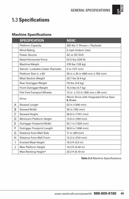
Machine Specifications
SPECIFICATION M20CPlatform Capacity 350 lbs (1 Person + Payload)
Wind Rating 0 mph (Indoor Use)
Power Source AC or DC Drill
Rated Horizontal Force 52.5 lbs (234 N)
Machine Weight 278 lbs (126 kg)
Swivel / Lockable Caster Diameter 5 in (127 mm)
Platform Size (L x W) 26 in x 30 in (660 mm x 762 mm)
Mast Section Weight 20.7 lbs (9.4 kg)
Rear Outrigger Weight 7.8 lbs (3.6 kg)
Front Outrigger Weight 10.3 lbs (4.7 kg)
Flat Free Transport Wheels 12 in x 3.5 in (305 mm x 89 mm)
DriveWorm Drive with Integrated Drive Gear & Brake
A Stowed Length 53 in (1346 mm)
B Stowed Width 30 in (762 mm)
C Stowed Height 56.6 in (1741 mm)
D Minimum Platform Height 12.9 in (329 mm)
E Outrigger Footprint Width 52.1 in (1324 mm)
F Outrigger Footprint Length 58.9 in (1496 mm)
G Distance from Wall Side 11 in (281mm)
H Distance from Wall Front 12.3 in (314 mm)
I Erected Mast Height 16.3 ft (5.0 m)
J Max Platform Height 14.3 ft (4.34 m)
Max Working Height* 20.3 ft (6.19 m)
5.3 Specifications
Table 5-2 Machine Specifications

PowerLift by ReechCraft46
SECT
ION
5 GENERAL SPECIFICATIONS
Figure 5-5 Machine Specifications
A
B
C
D
E
F
G
H
J
I
www.reechcraft.com/powerlift 888-600-6160 47
General
This section contains general safety precautions which must be observed during maintenance of the machine. It is important that maintenance personnel heed these warnings to avoid possible injury to themselves or others. A maintenance program must be established by a competent person and followed to ensure the machine is in safe operating condition.
Due to our commitment to continuous improvement, Reechcraft reserves the right to make specification changes without prior notification. Contact Reechcraft for updated information.
MODIFICATION OF THE MACHINE WITHOUT THE MANUFACTURERS APPROVAL IS A PROHIBITED PRACTICE AND A DIRECT SAFETY VIOLATION.
Your safety and the safety of others is the primary concern when performing service and maintenance on the machine. Always be conscious of moving parts and pinch points. Never leave an object in an unstable or unsupported position.
SINCE THE MANUFACTURER HAS NO DIRECT CONTROL OVER THE FIELD SERVICE AND MAINTENANCE OF THE MACHINE, SAFETY IS THE RESPONSIBILITY OF THE OWNER/OPERATOR.
6.1 Maintenance Safety Precautions
DANGER
NOTICE
CAUTION
WARNING
DANGER
NOTICE
CAUTION
WARNING
SECTION 6SERVICE & MAINTENANCE

PowerLift by ReechCraft48
Maintenance Safety
FAILURE TO COMPLY WITH THE SAFETY PRECAUTIONS LISTED IN THIS SECTION COULD RESULT IN MACHINE DAMAGE, PERSONNEL INJURY OR DEATH, AND IS A SAFETY VIOLATION
• REMOVE ALL RINGS, WATCHES, AND JEWELRY WHEN PERFORMING ANY MAINTENANCE.
• DO NOT WEAR LONG HAIR UNRESTRAINED OR LOOSE FITTING CLOTHING AND NECKTIES WHICH MAY BECOME CAUGHT OR ENTAGLED IN THE MACHINE
• OBSERVE, UNDERSTAND AND OBEY ALL DANGER, WARNING, CAUTION AND OTHER INSTRUCTIONS ON THE MACHINE AND IN OPERATORS MANUAL.
• KEEP STANDING SURFACES AND HAND HOLDS FREE OF GREASE, WATER, OIL, ETC.
• NEVER WORK UNDER AN ELEVATED PLATFORM UNTIL THE PLATFORM HAS BEEN SAFELY RESTRAINED FROM ANY MOVEMENT.
• BEFORE MAKING ANY ADJUSTMENTS OR PERFORMING ANY OTHER MAINTENANCE ON THE MACHINE, SHUT OFF ALL POWER.
• KEEP ALL OUTRIGGERS AND ATTACHMENTS STOWED IN THEIR PROPER PLACE.
• USE ONLY APPROVED, NONFLAMMABLE CLEANING SOLVENTS.
DANGER
NOTICE
CAUTION
WARNING
SECT
ION
6 SERVICE & MAINTENANCE
www.reechcraft.com/powerlift 888-600-6160 49
SECTION 6SERVICE & MAINTENANCE
General
This section provides the necessary information needed by those personnel that are responsible to place the machine in operational readiness and maintain its safe operating condition. To ensure maximum service life and safe operation, be sure that all inspections and maintenance has been completed before placing the machine into service.
Preparation, Inspection and Maintenance
It is important to establish a comprehensive inspection and preventative maintenance program. Table 2-1 outlines the periodic machine inspection and maintenance recommended by Reechcraft. Consult your local, regional or national regulations for further requirements. Note: the frequency of inspections must increase as environment and frequency of use requires.
Pre-Start InspectionIt is the operators responsibility to perform a Pre-Start Inspection of the machine prior to use. Reference Section 2 in this manual for Pre-Start Inspection procedures.
This manual must be read and understood in its entirety prior to performing a Pre-Start Inspection.
Frequent and Pre-Delivery Inspection
The Frequent Inspection and Pre-Delivery Inspection shall be performed by a competent person or a qualified mechanic.
The Frequent Inspection and Pre-Delivery Inspection procedures are performed in the same way but at different times. The Pre-Delivery Inspection shall be performed prior to each sale, lease, or rental delivery. The Frequent Inspection shall be performed on each machine in service for 3 months; out of service for more than 3 months; or when purchased used. The frequency of this inspection must increase as environment and frequency of use requires.
Reference the appropriate areas of this manual for service and maintenance procedures.
6.2 Machine Preparation, Inspection & Maintenance

PowerLift by ReechCraft50
Annual Machine Inspection
The Annual Machine Inspection must be performed by a competent person or a qualified mechanic on an annual basis, no later that 13 months from the date of the prior Annual Machine Inspection.
Reference the Service and Maintenance Sections if this manual and appropriate inspection form to complete this inspection.
5 Year Machine Inspection and Track Replacement
The Mast Coupling Pins, Cam Locks, Track and Climbing Unit must be inspected and the track replaced by an authorized Reechcraft Service Center when:
• The track is worn beyond specification (.1875”) See Figure 6-1
• The track is damaged, bent or corroded.
In conjunction with specified inspections, maintenance shall be performed by a competent person or a qualified mechanic.
SECT
ION
6 SERVICE & MAINTENANCE

www.reechcraft.com/powerlift 888-600-6160 51
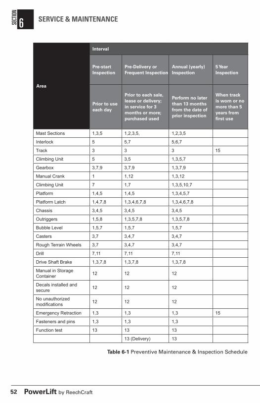
The preventive maintenance and inspection checks are listed and defined in the following table. The table is divided into two parts: “AREA” and “INTERVAL”. The component or function to be inspected are listed in the AREA column and the interval at which time they are to be inspected are listed in the INTERVAL column.
NOTE: The checks and services listed in this schedule are not intended to take the place of any local or regional regulations that may pertain to this type of equipment nor should the list be considered as all inclusive. Variances in interval times may occur due to the environment the machine is subjected to.
Inspection and Maintenance Codes:
1. Check for proper and secure installation
2. No gouges, excessive wear, or dents showing
3. Visually inspect for excessive wear, damage, cracks or distortion
4. Check for cracked or broken welds
5. Check area is clean and free of debris
6. Check for proper adjustment
7. Check for proper operation
8. Check for proper spring back
9. Check for signs of leakage
10. Check for proper tolerances
11. Check for proper specifications
12. Verify
13. Perform
14. Replace
15. Inspect per Operator’s Safety Manual
6.3 Preventive Maintenance & Inspection Schedule
SECTION 6SERVICE & MAINTENANCE
PowerLift by ReechCraft52
Area
Interval
Pre-start Inspection
Pre-Delivery or Frequent Inspection
Annual (yearly) Inspection
5 Year Inspection
Prior to use each day
Prior to each sale, lease or delivery; in service for 3 months or more; purchased used
Perform no later than 13 months from the date of prior inspection
When track is worn or no more than 5 years from first use
Mast Sections 1,3,5 1,2,3,5, 1,2,3,5
Interlock 5 5,7 5,6,7
Track 3 3 3 15
Climbing Unit 5 3,5 1,3,5,7
Gearbox 3,7,9 3,7,9 1,3,7,9
Manual Crank 1 1,12 1,3,12
Climbing Unit 7 1,7 1,3,5,10,7
Platform 1,4,5 1,4,5 1,3,4,5,7
Platform Latch 1,4,7,8 1,3,4,6,7,8 1,3,4,6,7,8
Chassis 3,4,5 3,4,5 3,4,5
Outriggers 1,5,8 1,3,5,7,8 1,3,5,7,8
Bubble Level 1,5,7 1,5,7 1,5,7
Casters 3,7 3,4,7 3,4,7
Rough Terrain Wheels 3,7 3,4,7 3,4,7
Drill 7,11 7,11 7,11
Drive Shaft Brake 1,3,7,8 1,3,7,8 1,3,7,8
Manual in Storage Container 12 12 12
Decals installed and secure 12 12 12
No unauthorized modifications 12 12 12
Emergency Retraction 1,3 1,3 1,3 15
Fasteners and pins 1,3 1,3 1,3
Function test 13 13 13
13 (Delivery) 13
Table 6-1 Preventive Maintenance & Inspection Schedule
SECT
ION
6 SERVICE & MAINTENANCE

www.reechcraft.com/powerlift 888-600-6160 53
General
The following information is provided to assist you in the use and application of service and maintenance procedures contained in this chapter. NOTE: Please refer to Service and Parts Manual for additional information.
WHEN AN ABNORMAL CONDITION IS NOTED AND PROCEDURES CONTAINED WITHIN THIS MANUAL DO NOT SPECIFICALLY RELATE TO THE NOTED IRREGULARITY, USE OF THE MACHINE SHOULD BE STOPPED AND A QUALIFIED MECHANIC WITH PROPER KNOWLEGE SHOULD CORRECT THE IRREGULARITY BEFORE WORK IS RESUMED.
Safety and Workmanship
Your safety, and that of others, is the first consideration when engaging in the maintenance of equipment. Always be conscious of moving components and pinch points. Do not allow heavy objects to rest in an unstable position. When raising a portion of the machine, ensure that adequate support is provided.
Cleanliness
The single most important item in preserving the long service life of a machine is to keep foreign materials out of the vital components. Reasonable precautions have been taken to safeguard against this. However, these areas must be maintained on a scheduled basis in order to preserve proper function of the machine.
DO NOT LUBRICATE THE MACHINE. ENSURE THAT THE MAST AND DRIVE SHAFT BRAKE ARE CLEAN AND FREE OF DEBRIS, OIL AND GREASE.
Component Disassembly and Reassembly
When disassembling or reassembling a component, complete the procedural steps in sequence. Do not partially disassemble or reassemble one part and then start another. Always recheck your work to assure that nothing has been overlooked. Do not make any adjustments, other than those recommended, without obtaining proper approval.
6.4 Servicing & Maintenance Guidelines
DANGER
NOTICE
CAUTION
WARNING
DANGER
NOTICE
CAUTION
WARNING
SECTION 6SERVICE & MAINTENANCE
PowerLift by ReechCraft54
6.5 Decal ReplacementAll decals must be mounted to the machine as specified and clearly legible.
Please see Figure 5-1 to Figure 5-4 and refer to table 5-1 for positions and Reechcraft part numbers.
To replace a damaged decal, first remove it completely without damaging the underlying surface.
Remove any remaining adhesive with a suitable solvent. Test the solvent on an inconspicuous area first to ensure it does not mark or damage the surface finish.
SURFACE DAMAGE COULD RESULT IN CORROSION AND STRUCTURAL DAMAGE.
Before applying the new decal, ensure the surface is clean and dry.
Remove the backing paper, apply the decal along one edge then seal it gently and evenly.
If there are any air bubbles, work them gently towards the edge with a clean cloth.
Pressure sensitive adhesives reach full strength after several days.
MAST SECTIONS SHOULD BE INSPECTED EVERY 3 MONTHS OR MORE FREQUENTLY DEPENDING ON ENVIRONMENT
The Mast Track sections should be inspected more frequently if used in a harsh environment or high duty cycle applications. Inspection should be more frequent as they approach the end of their useful lives. The periodic inspection shall cover all mast track sections on the machine.
Mast Track sections must be replaced by an Authorized Reechcraft Service Center.
Conditions such as the following shall be sufficient reason for questioning continued use of the machine or increasing the frequency of inspection.
SECT
ION
6 SERVICE & MAINTENANCE
DANGER
NOTICE
CAUTION
WARNING
6.6 Mast Track Inspection Procedure
DANGER
NOTICE
CAUTION
WARNING

www.reechcraft.com/powerlift 888-600-6160 55
1. Mast Track Wear
Check that the track is not worn (1875” tooth remaining) and that the galvanized surface is in good condition and no corrosion or excessive rust is present.
2. Mast Track Misalignment
Be sure that the track is aligned properly at the joint location. If the track is bent or damaged in any way, it must be replaced by a qualified mechanic before machine use may resume.
3. Mast Connector Wear
Mast Track misalignment may be due to worn or damaged coupling pins located in the Mast Connector. If any part of the connector is worn or and excessively loose when properly coupled and locked together, it must be replaced before machine use may resume.
SECTION 6SERVICE & MAINTENANCE
Figure 6-1 Mast / Track Alignment
Wear (.188”) Bent, Misshapen
Connector Wear
.020
.188”

PowerLift by ReechCraft56
This section contains troubleshooting information to be used for locating and correcting most of the operating problems which may develop in the machine. If a problem should develop which is not presented in this section, qualified guidance should be obtained before proceeding with any maintenance.
Troubleshooting Information
The troubleshooting procedures applicable to the product are listed and defined in Table 7-1, Troubleshooting Guide.
Each malfunction within an individual group or system is followed by a listing of probable causes which will enable the determination of the applicable corrective action. The probable causes and corrective action should, where possible, be checked in the order listed in the tables.
It should be noted that there is no substitute for thorough knowledge of the equipment and related systems.
It should be recognized that the majority of the problems arising in the machine will be centered in the power system. For this reason, every effort has been made to ensure that all likely problems in these areas are give the fullest possible treatment. In the remaining machine groups, only those problems which are symptomatic of greater problems which have more than one probable cause and remedy are included. This means that problems for which the probable cause and remedy may be immediately obvious are not listed in this section.
SECTION 7TROUBLESHOOTING
7.1 General

www.reechcraft.com/powerlift 888-600-6160 57
SECTION 7TROUBLESHOOTING
TROUBLE PROBABLE CAUSE REMEDY
Platform does not lift up from the fully lowered position - Drill motor starts
One or more interlocks are engaged
Check to be sure all four outriggers are properly installed extended and stable
Overload clutch is slipping
Be sure the rated load of 350 lbs is not exceeded and that the platform is free and clear of any obstruction or interference.
One or more interlock pins are wedged in the locked position.
Lower platform to the fully docked position to relieve pressure; ensure all leveling jacks are stable and bearing equal weight.
Platform will not move when in elevated position - Drill motor starts
Intermediate mast section is installed backwards with the track section facing away from the platform
Lower the platform and reinstall the mast section with the track section facing the platform.
One or more of the connector lock levers are in the open position interfering with the rollers
Lower the platform to expose the last section of mast that was installed and check to be sure both levers are completely engaged and locked in position.
The maximum height has been attained causing interference with the top termination plate
No remedy. System is functioning properly.
Platform moves sluggishly
Drive Shaft brake is engagedDepress the input shaft slightly before applying power to release the brake.
Drill battery not fully charged Charge battery
Drill has insufficient power or RPMBe sure the drill contains a motor of 7 amps and 1200 RPM or more.
Machine does not wheel properly
One or more castors are in the locked position
Unlock the castor
One or more castors are damaged Replace the damaged castor
Climbing Unit jumps or lurches while elevating
Track is damaged and missing teeth
Replace the track section*
*Performed by Authorized Reechcraft Service Center
TROUBLESHOOTING
Figure 7-1 Troubleshooting Guide

PowerLift by ReechCraft58
Notes:

www.reechcraft.com/powerlift 888-600-6160 59
Notes:

Reechcraft Inc.P.O. Box 2426
Fargo, ND 58108888.600.6160
www.reechcraft.com/powerlift