powerpoint presentation antennas in lte networks_5.antennas...space-frequency block coding (sfbc) in...
TRANSCRIPT

2

3
4
5

6

Space-Frequency Block Coding (SFBC)
In the case of two antenna ports, LTE transmit diversity is based on Space-Frequency Block Coding (SFBC). SFBC is the encoding scheme carried out in the frequency domains. Thus, space–frequency coding is applicable to OFDM and other “frequency-domain” transmission schemes. SFBC implies that two consecutive modulation symbols Si and Si+1 are mapped directly to frequency-adjacent resource elements on the first antenna port (Figure 4). On the second antenna port the frequency-swapped and transformed symbols Si+1*and Si* are mapped to the corresponding resource elements, where “*” denotes complex conjugate
7
8

Relevant concepts: CodewordData streams that are channel coded and rate controlled differently and separately are codewords.CDDCDD refers to cyclic delay diversity. The traditional delay diversity means transmission of the same signal of different delay versions in different antennas, therefore manually increasing the delay of the channel that the signal passes. CDD is designed for the OFDM system. Before a cyclic prefix (CP) is inserted, the same OFDM symbol is cyclic shifted by Dm samples (m=1, ……, M indicates the sequential antenna number), and then each antenna inserts its own CP to the corresponding cyclic shifted version. wherex is the transmitted signal,y is the received signal, H is the spatial channel matrix,Hij is the channel coefficient from the jth transmit antenna and the ith receive antenna. y=Hxy1=h11x1+h12x2+n1y2=h21x1+h22x2+n2The accuracy of the receiver in estimating the data transmitted by the transmitter has a negative correlation with the statistic correlation between vector (h11, h12) and vector (h21, h22). To lower the receiver complexity and reduce the signal interference between antennas, the eNodeB performs layer mapping and precoding for the modulated data before sending the data to the antenna ports, and converts the cross spatial channels into equivalent independent parallel channels.
9
Open Loop Spatial Multiplexing (OLSM)Open Loop Spatial Multiplexing (OLSM) is one of the downlink transmission modes that can support the higher data rate in current releases of LTE. OLSM consist of two transmit antennas at the eNB and two receive antennas at the UE (2x2 antenna configuration), sending either one or two simultaneous data streams from the eNB to the UE [9]. In a 2x2 antenna configuration, sending one data stream is known as Rank1 MIMO [9] and sending two data streams is known as Rank2 MIMO. The number of independent data streams that can be sent to the UE is restricted to either one or two stream, even if the number of transmit antennas at the eNB is increased to four. So a 2x2 configuration does not impose any overt simplification
9
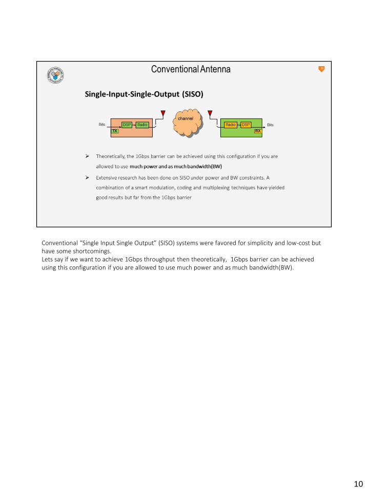
Conventional “Single Input Single Output” (SISO) systems were favored for simplicity and low-cost but have some shortcomings.Lets say if we want to achieve 1Gbps throughput then theoretically, 1Gbps barrier can be achieved using this configuration if you are allowed to use much power and as much bandwidth(BW).
10

So to attain high throughput like 1Gbps for a single user, multiple transmit and multiple receive antennas were being tried.It is observed that this system promises enormous data rates!
11
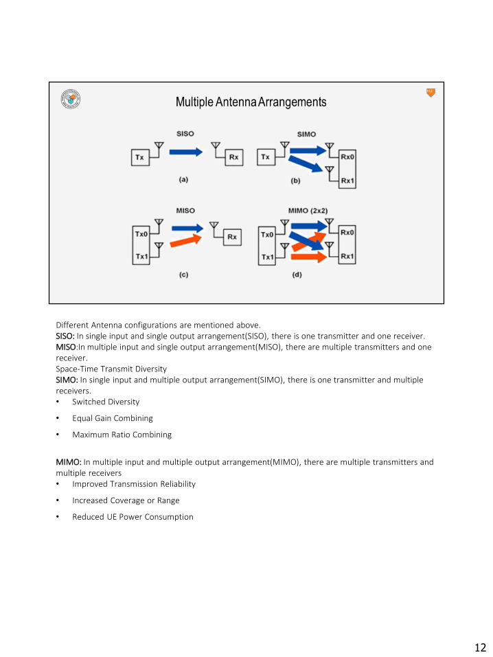
Different Antenna configurations are mentioned above.SISO: In single input and single output arrangement(SISO), there is one transmitter and one receiver.MISO:In multiple input and single output arrangement(MISO), there are multiple transmitters and one receiver.Space-Time Transmit DiversitySIMO: In single input and multiple output arrangement(SIMO), there is one transmitter and multiple receivers.• Switched Diversity
• Equal Gain Combining
• Maximum Ratio Combining
MIMO: In multiple input and multiple output arrangement(MIMO), there are multiple transmitters and multiple receivers• Improved Transmission Reliability
• Increased Coverage or Range
• Reduced UE Power Consumption
12

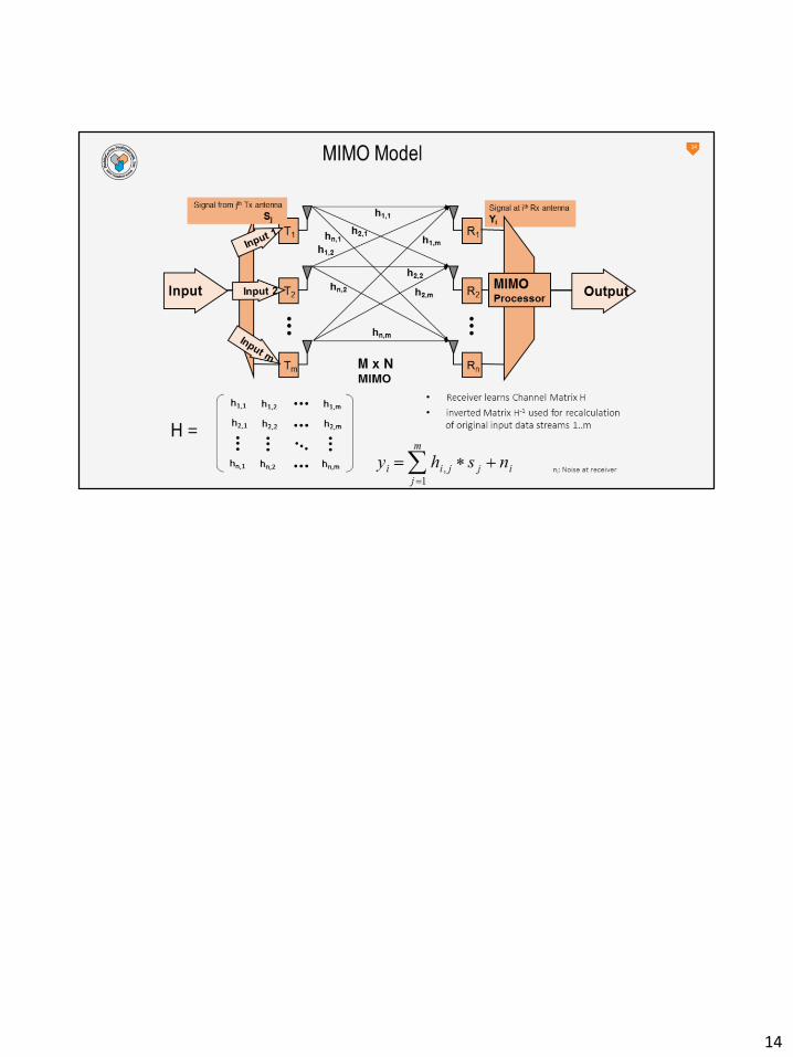
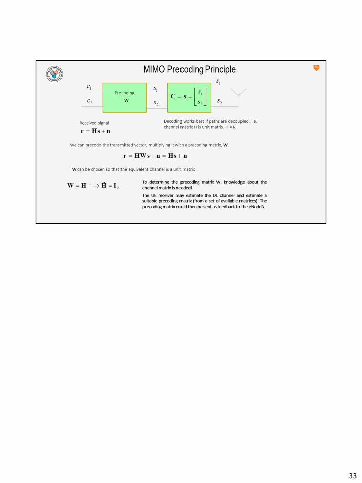
The basic mechanism behind MIMO is linear algebra. If we e.g. transmit N (=2) signals S0, S1 via twoantennas and receive the signal at M (=2) antennas R0, R1 then we can treat input vector S and outputR as vectors. Each antenna receives in principle the superposition of each input antenna. During thepropagation from input to output antenna there will be attenuation, time delay as well as additivenoise which also can be described by a vector N. This can be modeled by complex factors h(ik) wherethe phase is determined by the time delay and the norm represents the amplitude attenuation. Weend up with a matrix H that connects input with output vector. The receiver now needs to invert thematrix H to recover the original input signal vector S. One of major importance is, to keep the matrix Hso that it can be inverted. If it is singular, then MIMO will not work. Usually the input signals S are pre-coded at the receiver side to improve exactly this.
13
14
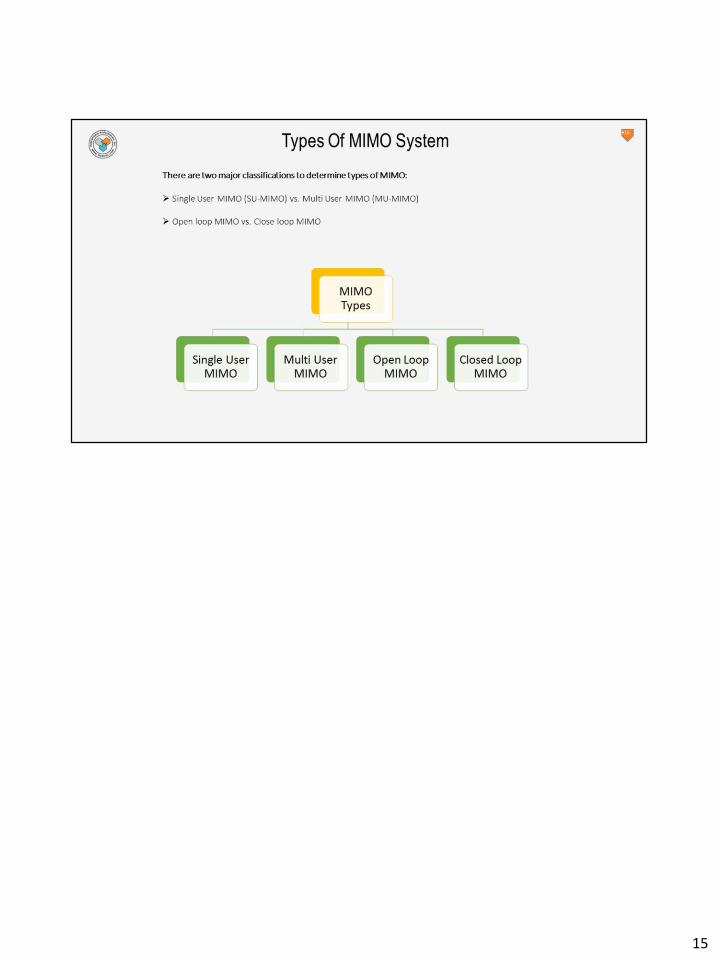
15

The single-user version of MIMO uses four simultaneous streams to boost data speed.User's Peak data rate: The use of multiple transmit antennas (e.g. 2 or 4) allows LTE to linearly increase the peak data rate by transmitting different modulation symbols from each transmit antenna using the same air interface resource (i.e. same sub-carrier at the same time). Such antenna technique is known as Single User Multiple Input Multiple Output (SU-MIMO) or Spatial Multiplexing (SM). The higher peak data rate increases the average throughput for the user and thus improves the end-user's Quality of Experience (QoE). In LTE, for a category 5 device, we can achieve 300 Mbps in the DL, if we utilize 4 transmit antennas at the eNB and allocate all resources of the 20MHz channel to a single user.
16
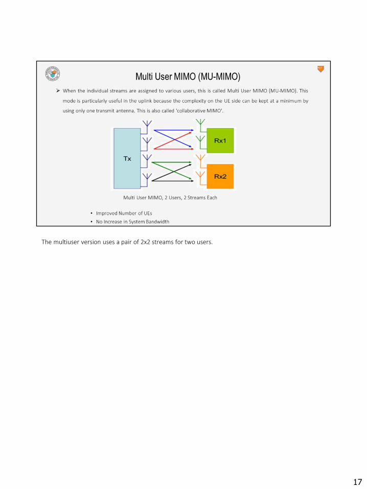
The multiuser version uses a pair of 2x2 streams for two users.
17

18

19
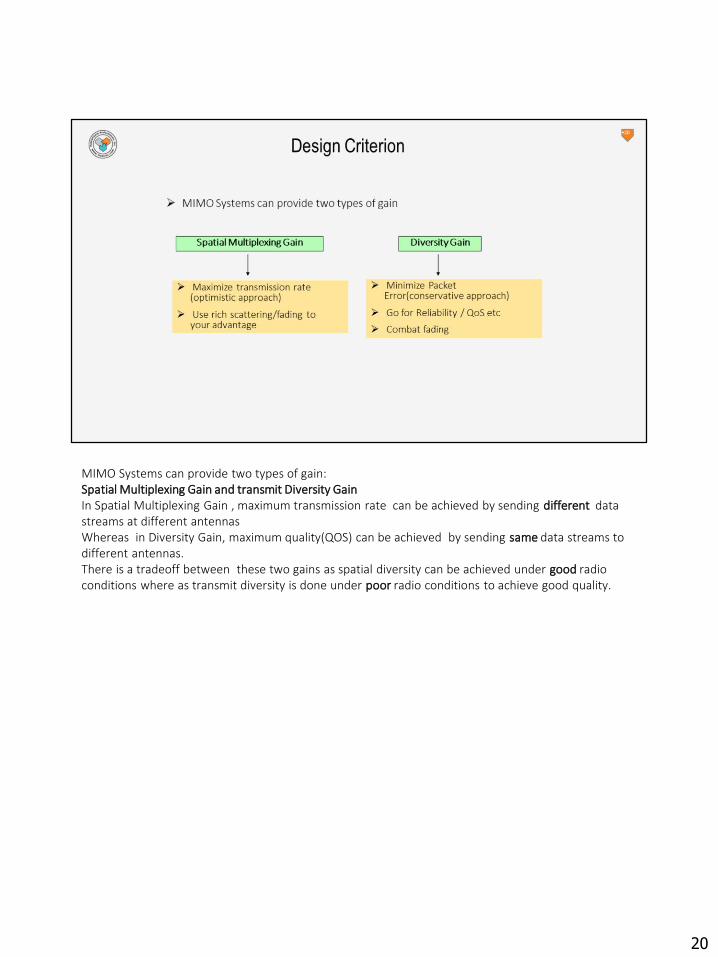
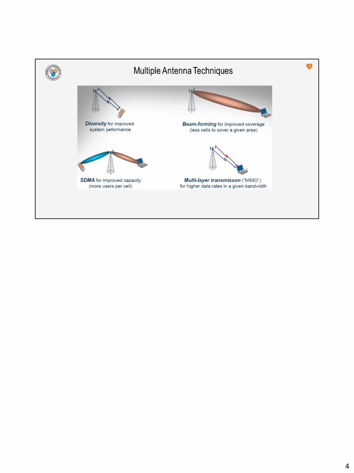
MIMO Systems can provide two types of gain:Spatial Multiplexing Gain and transmit Diversity GainIn Spatial Multiplexing Gain , maximum transmission rate can be achieved by sending different data streams at different antennasWhereas in Diversity Gain, maximum quality(QOS) can be achieved by sending same data streams to different antennas.There is a tradeoff between these two gains as spatial diversity can be achieved under good radio conditions where as transmit diversity is done under poor radio conditions to achieve good quality.
20

Typically, close to the eNodeB Spatial multiplexing could be used to improve the throughput at the cell edge where as transmission diversity could be used to improve the coverage .Table mentioned above shows the kind of gain for transmission diversity and spatial multiplexing respectively.In transmission diversity, we can have a gain of 3-5 dB in the downlink link budget with 2*2 MIMO whereas in spatial multiplexing, we can increase our throughput by 100% and 300% with 2*2 and 4*4 MIMO respectively.
22
23
24

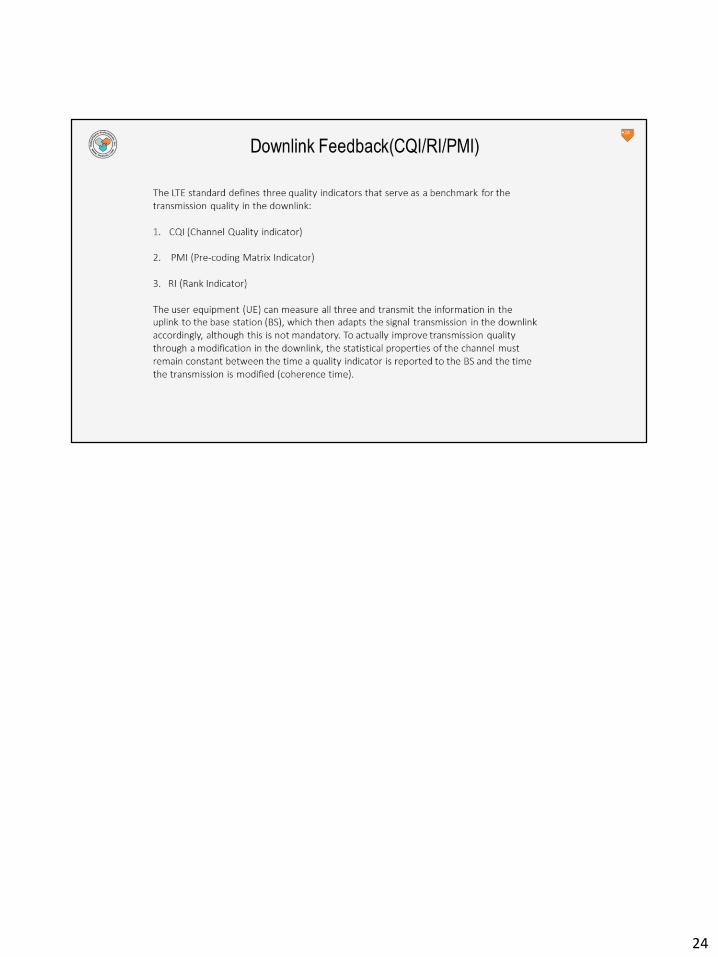
CQI MeasurementsThe most important part of channel information feedback is the Channel Quality Indicator (CQI). The CQI provides the eNodeB information about the link adaptation parameters the UE can support at the time. The CQI is defined as a table containing 16 entries with Modulation and Coding Schemes (MCSs). The UE reports back to the eNodeB the highest CQI index corresponding to the MCS and TBS(transport block size) for which the estimated received DL transport block BLER shall not exceed 10%. The CQI operation has a high degree of similarity with HSDPA CQI use. Note that there are many more possibilities for MCS and TBS size values than only those 15 indicated by the CQI feedback.
25
26
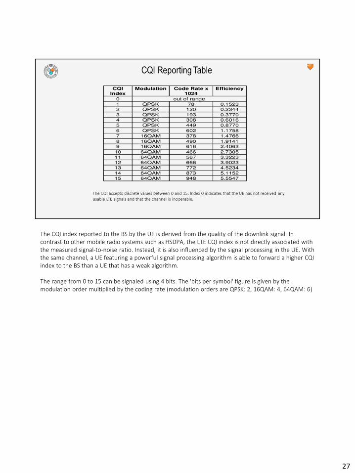
The CQI index reported to the BS by the UE is derived from the quality of the downlink signal. In contrast to other mobile radio systems such as HSDPA, the LTE CQI index is not directly associated with the measured signal-to-noise ratio. Instead, it is also influenced by the signal processing in the UE. With the same channel, a UE featuring a powerful signal processing algorithm is able to forward a higher CQI index to the BS than a UE that has a weak algorithm.
The range from 0 to 15 can be signaled using 4 bits. The 'bits per symbol' figure is given by the modulation order multiplied by the coding rate (modulation orders are QPSK: 2, 16QAM: 4, 64QAM: 6)
27
28

Rank Indicators (RI) are applicable to the open and closed loop transmission modes which are able to use more than a single layerbetween the layer mapping and precoding functions:transmission mode 3: open loop spatial multiplexingtransmission mode 4: closed loop spatial multiplexingtransmission mode 8: dual layer multi-user MIMO (3GPP release 9)transmission mode 9: closed loop spatial multiplexing with up to 8 layers (3GPP release 10)The UE uses the RI to provide the eNode B with a suggestion regarding the number of layers to be generated during layer mapping
29

30
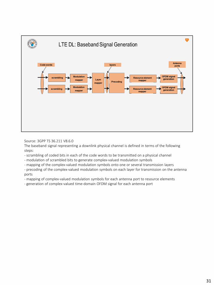
Source: 3GPP TS 36.211 V8.6.0 The baseband signal representing a downlink physical channel is defined in terms of the following steps: - scrambling of coded bits in each of the code words to be transmitted on a physical channel - modulation of scrambled bits to generate complex-valued modulation symbols - mapping of the complex-valued modulation symbols onto one or several transmission layers - precoding of the complex-valued modulation symbols on each layer for transmission on the antenna ports - mapping of complex-valued modulation symbols for each antenna port to resource elements - generation of complex-valued time-domain OFDM signal for each antenna port
31

32
33
34

35
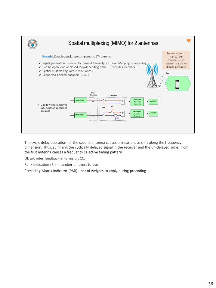
The cyclic delay operation for the second antenna causes a linear phase shift along the frequency dimension. Thus, summing the cyclically delayed signal in the receiver and the un-delayed signal from the first antenna causes a frequency selective fading pattern
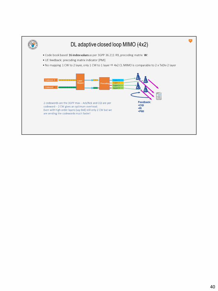
UE provides feedback in terms of: CQI
Rank Indication (RI) – number of layers to use
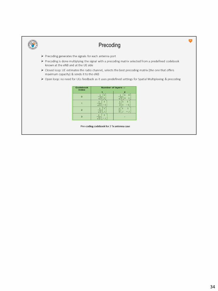
Precoding Matrix Indicator (PMI) – set of weights to apply during precoding
36
37
38
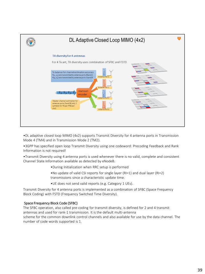
•DL adaptive closed loop MIMO (4x2) supports Transmit Diversity for 4 antenna ports in Transmission Mode 4 (TM4) and in Transmission Mode 2 (TM2).
•3GPP has specified open loop Transmit Diversity using one codeword: Precoding Feedback and Rank Information is not required!
•Transmit Diversity using 4 antenna ports is used whenever there is no valid, complete and consistent Channel State Information available as detected by eNodeB.
•During Initialization when RRC setup is performed
•No update of valid CSI reports for single layer (RI=1) and dual layer (RI=2) transmissions since a characteristic update time.
•UE does not send valid reports (e.g. Category 1 UEs).
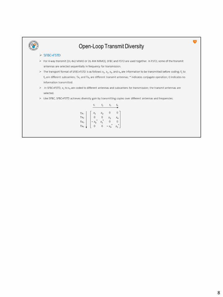
Transmit Diversity for 4 antenna ports is implemented as a combination of SFBC (Space Frequency Block Coding) with FSTD (Frequency Switched Time Diversity).
Space Frequency Block Code (SFBC)The SFBC operation, also called pre-coding for transmit diversity, is defined for 2 and 4 transmit antennas and used for rank-1 transmission. It is the default multi-antennascheme for the common downlink control channels and also available for use by the data channel. The number of code words supported is 1.
39
40
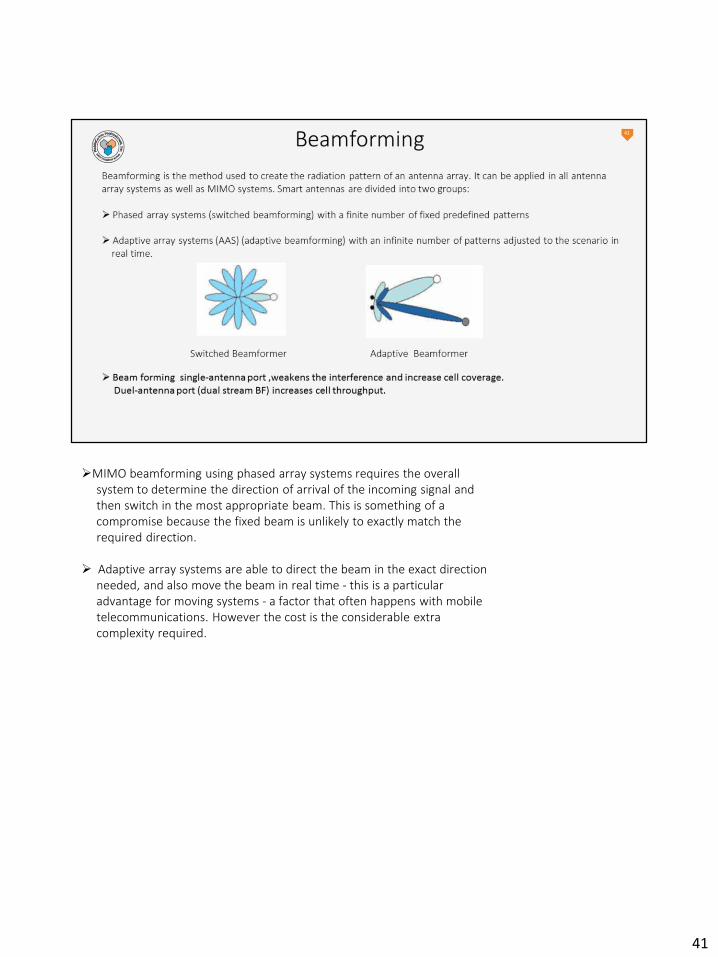
MIMO beamforming using phased array systems requires the overall system to determine the direction of arrival of the incoming signal and then switch in the most appropriate beam. This is something of a compromise because the fixed beam is unlikely to exactly match the required direction.
Adaptive array systems are able to direct the beam in the exact direction needed, and also move the beam in real time - this is a particular advantage for moving systems - a factor that often happens with mobile telecommunications. However the cost is the considerable extra complexity required.
41
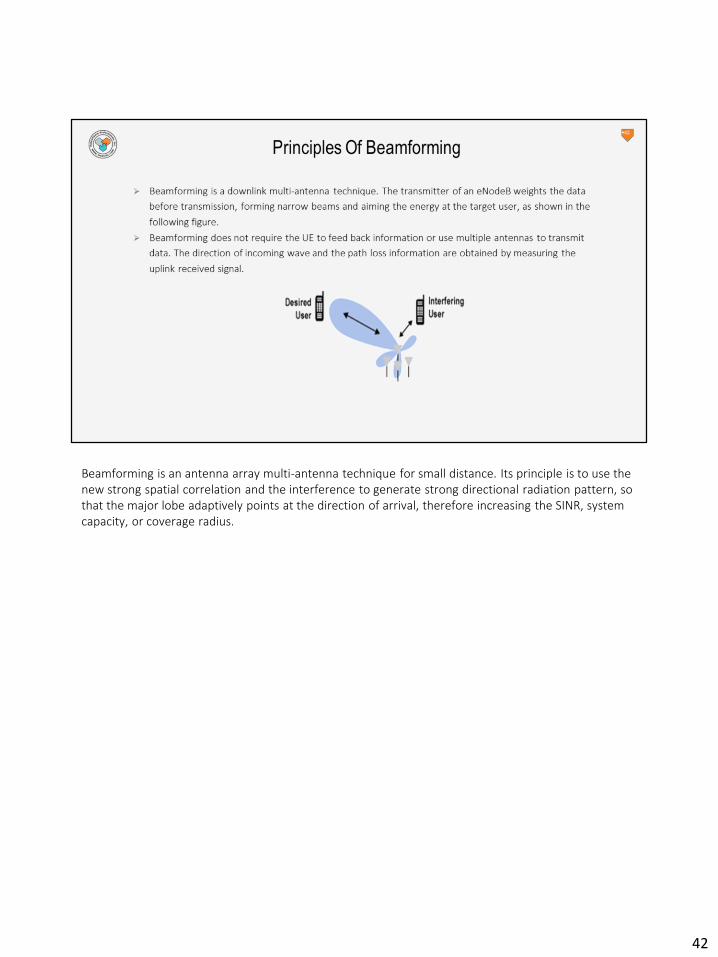
Beamforming is an antenna array multi-antenna technique for small distance. Its principle is to use the new strong spatial correlation and the interference to generate strong directional radiation pattern, so that the major lobe adaptively points at the direction of arrival, therefore increasing the SINR, system capacity, or coverage radius.
42

Beamforming:• Beamforming is similar to closed-loop MIMO but does not require the UE to
feed back information. The TDD system performs measurement accurately by using the uplink channels. Single-stream beamforming (TM7) or multi-stream beamforming (TM8/TM9) is supported.
• If the UE supports single input, the system cannot use one antenna to estimate the channel of another antenna, leading to some loss.
• Beamforming requires low UE mobility.
43
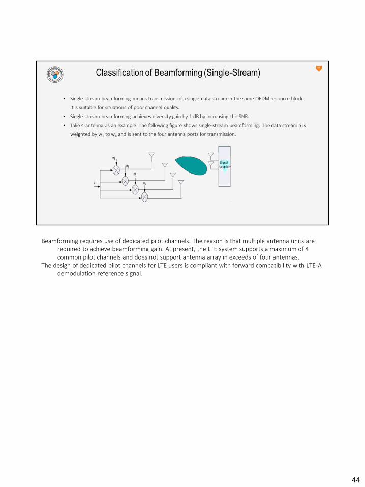
Beamforming requires use of dedicated pilot channels. The reason is that multiple antenna units are required to achieve beamforming gain. At present, the LTE system supports a maximum of 4 common pilot channels and does not support antenna array in exceeds of four antennas.
The design of dedicated pilot channels for LTE users is compliant with forward compatibility with LTE-A demodulation reference signal.
44

• Dual-stream beamforming achieves large capacity gain but requires high UE SNR (near the eNodeB). The following is a case of China Mobile.
• The LTE TDD system uses 8-antenan dual-stream beamforming. In comparison with the 2-antenna MIMO, the sector throughput is increased by 80% and the edge throughput is increased by 130%.
• The cell coverage radius of the 8-antenna dual-stream beamforming is significantly increased compared with that of the 2-antenna MIMO to 300 m, by 1.5 to 2 times. 8-antenna dual-stream beamforming and TD-SCDMA can be co-site and co-coverage, lowering the LTE TDD network construction cost.
45
46

47
48

