powerpoint presentation - slide 1. david... · ... (stalling, rolling and adverse yaw) 2....
TRANSCRIPT

Presentation 2011
Thrive Technology & Innovation Club
Friday 15th July
Spanwise Lift Distributions
RAeS 2015 Light Aircraft Design Conference 16th November 2015

Who is Swift?
Swift comprises a group of seven companies with an underlying core competence of fluid dynamics. Currently we have two main developments: 1. New two seat aircraft 2. New concept Vertical Axis Wind Turbine

What is the Swift Aircraft?
The concept of the Swift is to produce a one airframe “Multi-Function Platform” that will fulfil a variety of requirements and missions. The primary role is a two seat fully aerobatic (+/- 6g) training platform. The flight characteristics will be forgiving enough for absolute beginners while being robust, powerful and sufficiently agile for military ab initio training. It will also be
suitable and desirable as a fast tourer with good endurance, a comfortable cockpit and excellent load capacity. Spacious, Efficient, Effective, Competent; The Swift is conceived to be the appropriate tool for the job, whatever that may be. The choice will be yours.

What is the Swift Aircraft?
The Swift will be a continuation of other well known training aircraft

What is the Swift Aircraft?
Attention has been paid to conspicuity mainly due to recent accidents involving mainly white composite aircraft (power as well as non powered). By use of correct adhesives we can offer “coloured” aircraft. Design Tg is 108°C to cope with black colours in sunny climates. This is unique for a composite aircraft of this type.

Design Approach?
The design team is tool. We have implemented a philosophy that is described below. There is a high reliance on our core spreadsheet tool.

Why are Spanwise Distributions important? Knowledge of the spanwise lift distribution is important for two main considerations: 1. Flying Characteristics (Stalling, Rolling and Adverse Yaw) 2. Structural Considerations Essentially we are trying to solve the following equation, which in its raw form is as follows. As the unknown circulation Г is on both sides of the equation then the integral cannot be evaluated in simple terms.
2Γ
m0𝑐𝑉= 𝛼𝑎 −
1
4𝜋𝑉 𝑑Γ
𝑦′ − 𝑦
𝑦=𝑏2
𝑦=−𝑏2
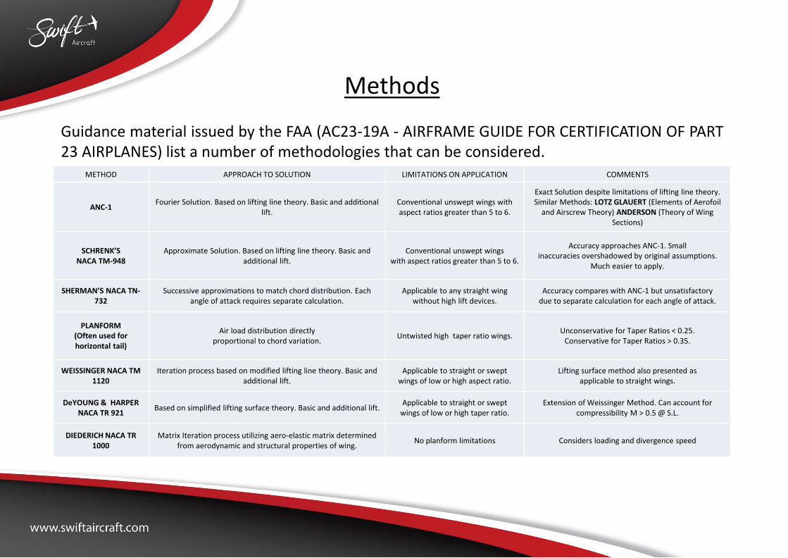
Methods Guidance material issued by the FAA (AC23-19A - AIRFRAME GUIDE FOR CERTIFICATION OF PART 23 AIRPLANES) list a number of methodologies that can be considered.
METHOD APPROACH TO SOLUTION LIMITATIONS ON APPLICATION COMMENTS
ANC-1 Fourier Solution. Based on lifting line theory. Basic and additional
lift. Conventional unswept wings with aspect ratios greater than 5 to 6.
Exact Solution despite limitations of lifting line theory. Similar Methods: LOTZ GLAUERT (Elements of Aerofoil
and Airscrew Theory) ANDERSON (Theory of Wing Sections)
SCHRENK’S NACA TM-948
Approximate Solution. Based on lifting line theory. Basic and additional lift.
Conventional unswept wings with aspect ratios greater than 5 to 6.
Accuracy approaches ANC-1. Small inaccuracies overshadowed by original assumptions.
Much easier to apply.
SHERMAN’S NACA TN-732
Successive approximations to match chord distribution. Each angle of attack requires separate calculation.
Applicable to any straight wing without high lift devices.
Accuracy compares with ANC-1 but unsatisfactory due to separate calculation for each angle of attack.
PLANFORM (Often used for horizontal tail)
Air load distribution directly proportional to chord variation.
Untwisted high taper ratio wings. Unconservative for Taper Ratios < 0.25.
Conservative for Taper Ratios > 0.35.
WEISSINGER NACA TM 1120
Iteration process based on modified lifting line theory. Basic and additional lift.
Applicable to straight or swept wings of low or high aspect ratio.
Lifting surface method also presented as applicable to straight wings.
DeYOUNG & HARPER NACA TR 921
Based on simplified lifting surface theory. Basic and additional lift. Applicable to straight or swept
wings of low or high taper ratio. Extension of Weissinger Method. Can account for
compressibility M > 0.5 @ S.L.
DIEDERICH NACA TR 1000
Matrix Iteration process utilizing aero-elastic matrix determined from aerodynamic and structural properties of wing.
No planform limitations Considers loading and divergence speed

Methods (Other) There are a number of other published methods including.
METHOD Title Author / Year COMMENTS
NACA Report Number 585 Span Load Distribution for Taper Wings with Partial Span Flaps H.A Pearson / 1937
NACA Technical Note 606 Empirical Correlations to the Span Load Distribution at the Tip H.A Pearson / 1937 Tip corrections for Taper Ratios above 0.5.
NACA Technical Note 1269 Method for Calculating Wing Characteristics by Lifting Line Theory using
Non-Linear Section Lift Data J.C. Sivells and R. H. Neely / 1947
ARC R&M 2884 Methods for Calculating the Lift distribution of Wings H. Multhopp / 1950
Based on Lifting Surface as opposed to Lifting Line so is “valid” for more complex
configurations
NACA Technical Note 2751 A Simple Approximate Method for Calculating Spanwise Lift Distributions
and Aerodynamic Influence Coefficients at Subsonic Speeds F. W. Diederich / 1952
Methods (CFD)

Methods (Selected) In this presentation we shall only consider in detail the following: Schrenk NACA TM-948: Spanwise distribution is an average of the ideal elliptical distribution and the actual chord distribution. Is based on geometric consideration. ANC-1 (Issued by Army-Navy-Commerce Committee on Aircraft Requirements 1938)
These are the methods commonly referenced in design texts as well as those most commonly used to validate Light Aircraft through the LAA, CAA and EASA.

Schrenk (NACA TM-948) The use of Schrenk (NACA TM-948) is accurate for lift prediction of plain wings with and without twist as the extracted figure below demonstrates. However it does not consider the effect of drag (the impact of this will be shown later). The solid lines are the predictions with the Schrenk method whereas the dashed lines are determined by the exact methods of Multhopp’s (ARC Reports and Memoranda No. 2884)

Schrenk (NACA TM-948) Inaccuracies in the lift distribution become apparent when flap or aileron deflections are considered that leads to discontinuities at the extremities of the control surfaces. The solid lines are the predictions with the Schrenk method whereas the dashed lines are determined by the exact methods of Multhopp’s (ARC Reports and Memoranda No. 2884)
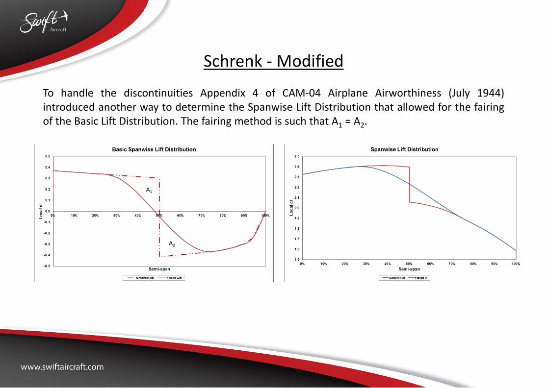
Schrenk - Modified To handle the discontinuities Appendix 4 of CAM-04 Airplane Airworthiness (July 1944) introduced another way to determine the Spanwise Lift Distribution that allowed for the fairing of the Basic Lift Distribution. The fairing method is such that A1 = A2.
A1
A2
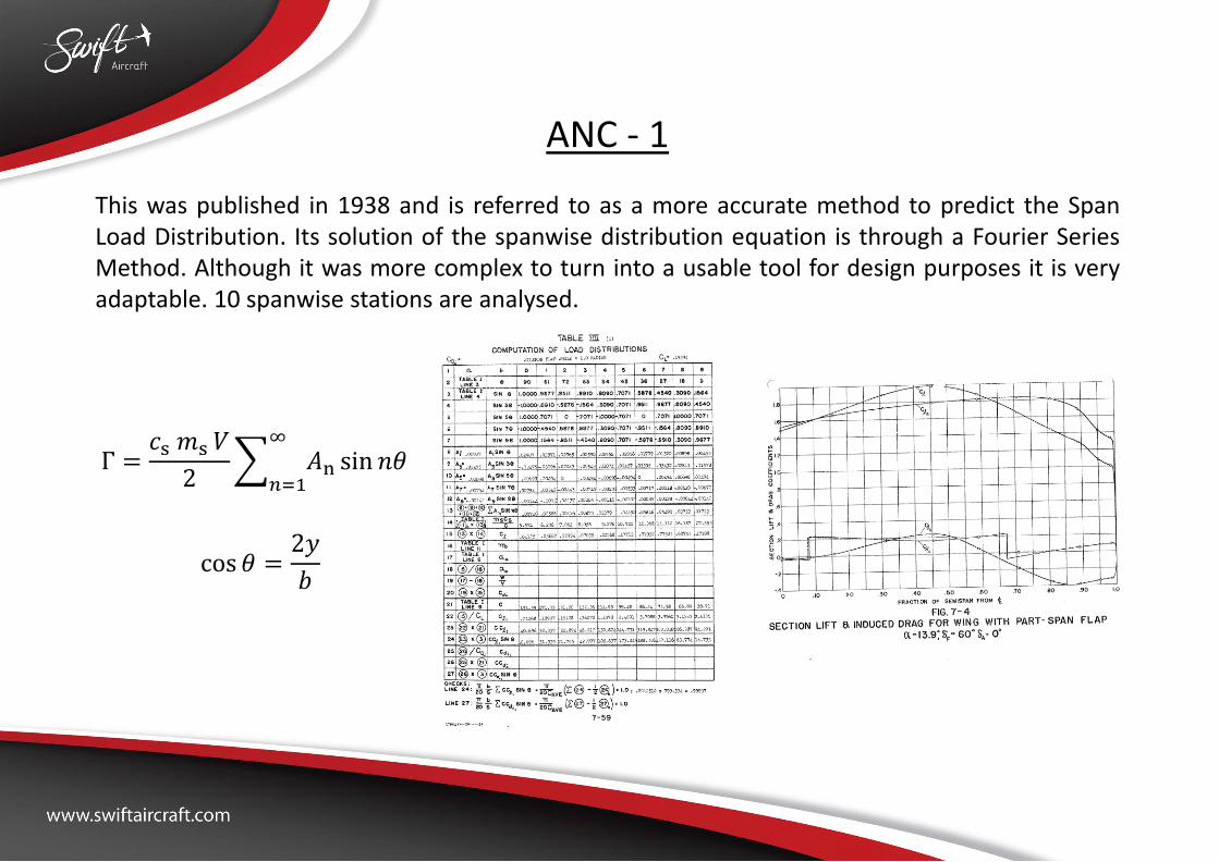
ANC - 1 This was published in 1938 and is referred to as a more accurate method to predict the Span Load Distribution. Its solution of the spanwise distribution equation is through a Fourier Series Method. Although it was more complex to turn into a usable tool for design purposes it is very adaptable. 10 spanwise stations are analysed.
Γ =𝑐s 𝑚s 𝑉
2 𝐴n sin 𝑛𝜃 ∞
𝑛=1
cos 𝜃 =2𝑦
𝑏
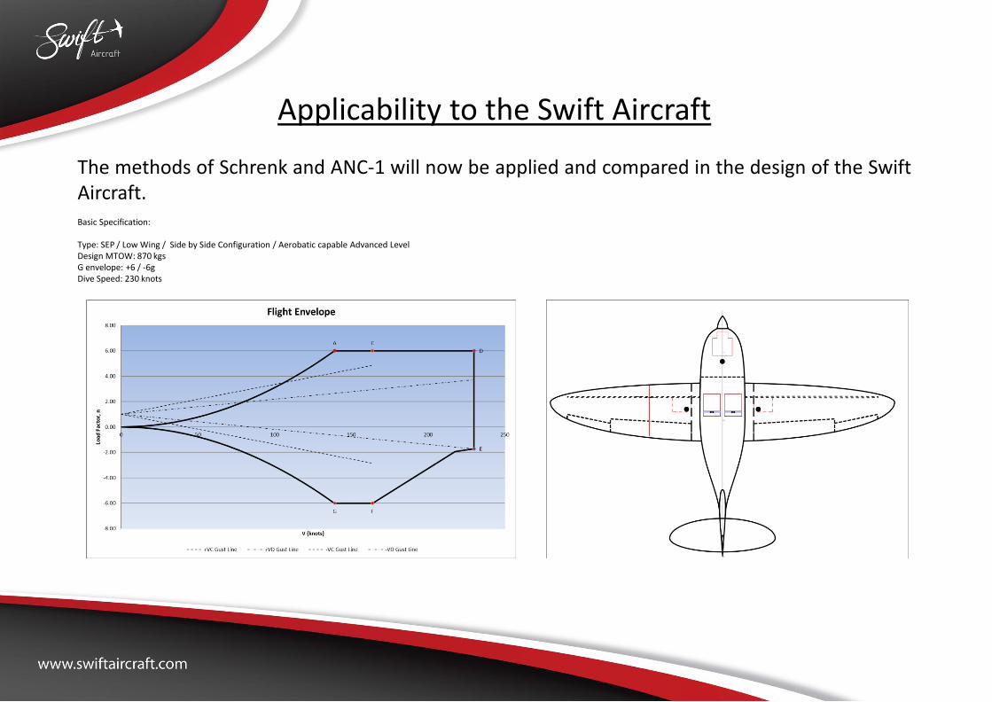
Applicability to the Swift Aircraft The methods of Schrenk and ANC-1 will now be applied and compared in the design of the Swift Aircraft. Basic Specification: Type: SEP / Low Wing / Side by Side Configuration / Aerobatic capable Advanced Level Design MTOW: 870 kgs G envelope: +6 / -6g Dive Speed: 230 knots

Applicability to the Swift Aircraft If we look at Point A of the V-N Diagram we arrive at the following comparison. VA = 139.1 knots In the analysis we always recommend that the Lift Curve Slope is amended for Reynolds number down its span. Methods can be found with Datcom and ESDU. The LCS is needed for both methods. For this design point the spanwise distribution is comparable.

Applicability to the Swift Aircraft If we look at the 2g point with flaps deflected [Ref: CS 23.345 (a) (1)]. The applicable velocity is determined per CS 23.345 (b). Vflap = 87.2 knots. Flap deflection = 40°. For this design point the spanwise distribution is showing “substantial” differences. The results of the CAM04method with and without fairing are shown. The CAM04 fairing methods have led to a seemingly unrealistic inboard lift distribution. This is due to the flap starting at 18.03% of the semi-span.

Applicability to the Swift Aircraft Do the differences matter? From a structural perspective the Root Rib of the wing is located at a semispan station of 18.03%. Therefore the loading inboard of that can be ignored as it is effectively “carried” by the fuselage.
In order to consider this we shall take a look at the shear force and bending moment diagrams.

Applicability to the Swift Aircraft Do the differences matter? Shear Force. Per methods of CAM04 Root Rib Shear = 10717 N. Per methods of ANC (1) Root Rib Shear = 11006 N
Difference is negligible.
CAM 04 ANC (1)

Applicability to the Swift Aircraft Do the differences matter? Bending Moment. Per methods of CAM04 Root Rib BM = 16955 Nm. Per methods of ANC (1) Root Rib BM = 16978 Nm
Difference is again negligible.
CAM 04 ANC (1)

Applicability to the Swift Aircraft How about the lack of drag prediction? As mentioned earlier one circumstance that is missed with Schrenk is the prediction of the induced drag profile. Structurally this is of small consequence as shown below. This is for V-N Case C that provides the highest Bending Moment
Difference is once again negligible. However it is needed for more accurate induced drag calculations for overall performance and adverse yaw predictions.
ANC-1 (With drag)
Aerodynamic loading only
Max BM = 52740 Nm
ANC (1) (Without drag)
Aerodynamic loading only
Max BM = 52093 Nm

Applicability to the Swift Aircraft Impact of Inertial Relief? With this slide we just want to draw attention to the impact of inertial relief. Irrespective of the method that is employed to determine the aerodynamic loading there are substantial benefits to include for the mass distribution along the wing.
Here the advantage is 12.4%. However depending upon the actual configuration it may be much more – or less !!
ANC-1
Aerodynamic loading only
Max BM = 52740 Nm
ANC (1)
With inertial relief
Max BM = 46197 Nm
12.4% reduction!

Applicability to the Swift Aircraft Impact of Inertial Relief? Ignoring inertial relief during the initial design can also be considered as “having some loose change” in the design. This can either account for weight increase during detailed design or expansion room in the future (powerplants, avionics, etc.)
With regards to drop tanks, wing positioned undercarriage, outboard fuel tanks all can reduce the shear along the wing and therefore reduce the root bending moment. However impact on flying performance is just as important as structural weight reduction through reduced loadings so a compromise always need to be found.
Step changes are point loads. Here
they represent the wing ribs

Applicability to the Swift Aircraft Do not forget the added loading due Torque around the main spar……. The torque distribution is key for the stresses in the wing skin. In the breakdown below it can be seen that for this case the main contributor to the total torque is the pitching moment of the airfoil as opposed to the distance of the AC from the spar.
For this case the limit torque is -3556 Nm By changing the position of the spar the torque distribution can reduce thus leading to some structural optimisation.

Applicability to the Swift Aircraft Do not forget the added loading due Torque around the main spar……. To show how the torque around the spar can be reduced we have relocated the spar from 25% of the centreline chord to 33.75%. The total torque has “reduced” from -3556 Nm to 0 Nm
Spar relocation may lead to other consequences like a heavier spar due to reduced height variation along its length. All things should be considered together.

ANC – 1 Advantages In our opinion the main advantages of the ANC-1 method are: 1. No need for blending functions to iron out discontinuities. 2. Very little additional computational effort to include drag predictions – better to have proof
that the impacts are negligible. Maybe for one design scenario they might not be. 3. Very simple to add the effect of wing twist, flap and aileron deflections.
In this figure we show the impact of full deflection of the ailerons at VA (Manoeuvring Speed – Point A of the V-N Diagram)

ANC – 1 Advantages In this slide we simply add the basic lift distribution from a 40° flap deflection. Combining the basic lift distribution of the full aileron deflection in combination with the additional lift we can see the impact for this improbable flight condition:
For this case the wing root bending moment increased from 55807 Nm to 101740 Nm. For the Swift Aircraft this would lead to structural failure !! In addition will be the effect of torsion at the wing root. With ANC – 1 cases like this are very easy to evaluate.
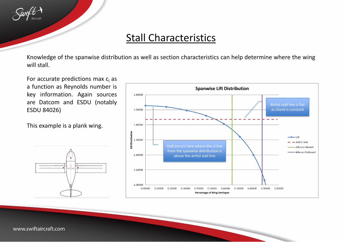
Stall Characteristics Knowledge of the spanwise distribution as well as section characteristics can help determine where the wing will stall.
For accurate predictions max cl as a function as Reynolds number is key information. Again sources are Datcom and ESDU (notably ESDU 84026) This example is a plank wing.
Stall occurs here where the cl line from the spanwise distribution is
above the airfoil stall line
Airfoil stall line is flat as chord is constant

Stall Characteristics To determine the stall speed simply increase the flying speed until the spanwise cl distribution falls below the airfoil stall line.
For this case the speed is 56.6 knots.

Stall Characteristics This is now the same wing (Area, Aspect Ratio and 0° Twist) but with a taper ratio of 0.45.
The location where the stall will start has moved outboard. This is the consequence of applying taper. For this case the stall speed has reduced to 55.1 knots.
Stall occurs here close to where. In this example, the ailerons are
due to start
Airfoil stall line inclined due to lower tip Reynolds numbers

Stall Characteristics This is now the same wing (Area and Aspect Ratio) but with an exaggerated twist of 10° so the general effect can be seen.
The location where the stall will start has moved more inboard. This is the general the consequence of applying twist. For this case the stall speed has reduced to 54.7 knots.
Point of stall has moved further inboard
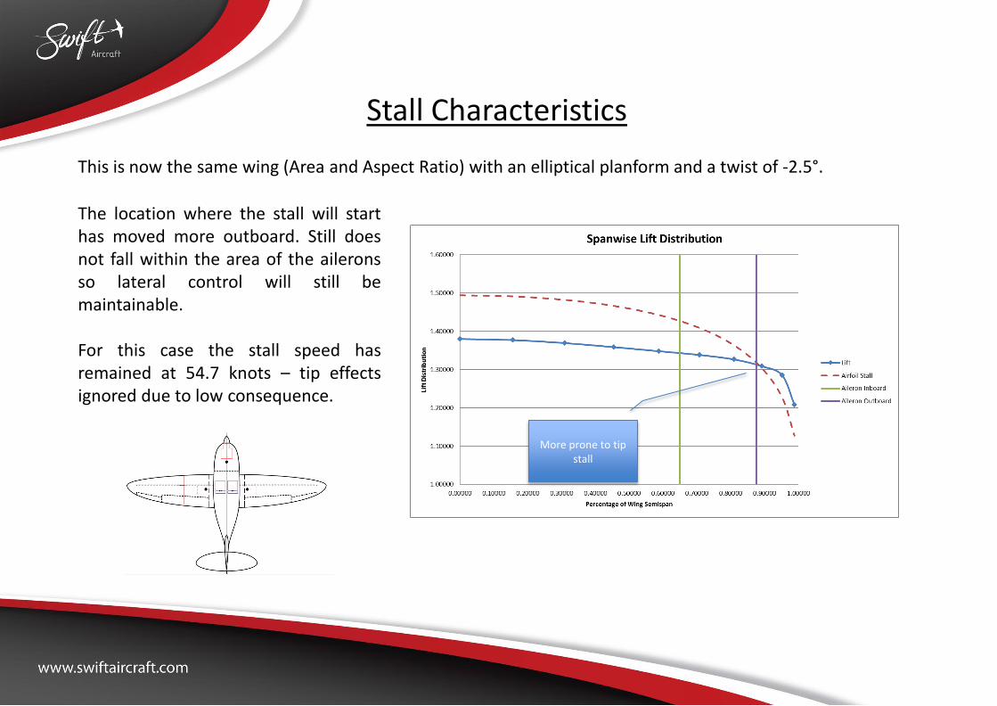
Stall Characteristics This is now the same wing (Area and Aspect Ratio) with an elliptical planform and a twist of -2.5°.
The location where the stall will start has moved more outboard. Still does not fall within the area of the ailerons so lateral control will still be maintainable. For this case the stall speed has remained at 54.7 knots – tip effects ignored due to low consequence.
More prone to tip stall

Roll Characteristics When the spanwise distribution due to aileron deflection is computed the ANC-1 provides a method to easily determine the rolling moment coefficient.
From this the effect of aileron deflection on rolling moment and consequently rate of roll can be determined. The latter requires knowledge of the Damping Moment that can also be derived from ANC-1. Different aileron configurations are easy to model

Yaw Characteristics When the spanwise distribution due to aileron deflection is computed the ANC-1 provides a method to easily determine the yawing moment coefficient.
Again rate of yaw can be determined from this information.

Conclusions Overall the ANC-1 method provides many useful numbers that are not “direct outputs” of the Schrenk methodology. Although it takes longer to put into a useful tool (easy to package into a spreadsheet) it provides the means to carryout more meaningful design optimisations.

Q&A