powerware 9390 integrated battery cabinet (models ibc-s ... · refer to the powerware 9390 ups...
TRANSCRIPT

Powerware 9390Integrated Battery Cabinet (Models IBC-S and IBC-L)Installation Manual
®

IMPORTANT SAFETY INSTRUCTIONSSAVE THESE INSTRUCTIONS
This manual contains important instructions that you should follow during installation and
maintenance of the UPS and batteries. Please read all instructions before operating the equipment
and save this manual for future reference.
Consignes de sécurité
CONSIGNES DE SÉCURITÉ IMPORTANTESCONSERVER CES INSTRUCTIONS
CE MANUEL CONTIENT DES CONSIGNES DE SÉCURITÉ IMPORTANTES
Powerware is a registered trademark of Eaton Electrical Inc.
�Copyright 2004–2006 Eaton Corporation, Raleigh, NC, USA. All rights reserved. No part of this document may be
reproduced in any way without the express written approval of Eaton Corporation.

iEATON Powerware® 9390 Integrated Battery Cabinet (Models IBC-S and IBC-L) Installation Manual � 164201536 Rev Dwww.eaton.com/powerquality
Table of Contents
1 Introduction 1-1 . . . . . . . . . . . . . . . . . . . . . . . . . . . . . . . . . . . . . . . . . . . . . . . . . . . . . . . . . . . .
1.1 Battery Cabinet Configurations 1-2 . . . . . . . . . . . . . . . . . . . . . . . . . . . . . . . . . . . . . . . . . . . . . .
1.2 UPS Systems Using Powerware 9390 Battery Cabinets 1-2 . . . . . . . . . . . . . . . . . . . . . . . . . . .
1.3 Using This Manual 1-3 . . . . . . . . . . . . . . . . . . . . . . . . . . . . . . . . . . . . . . . . . . . . . . . . . . . . . . . . .
1.4 Conventions Used in This Manual 1-3 . . . . . . . . . . . . . . . . . . . . . . . . . . . . . . . . . . . . . . . . . . . .
1.5 Safety Warnings 1-4 . . . . . . . . . . . . . . . . . . . . . . . . . . . . . . . . . . . . . . . . . . . . . . . . . . . . . . . . . . .
1.6 For More Information 1-5 . . . . . . . . . . . . . . . . . . . . . . . . . . . . . . . . . . . . . . . . . . . . . . . . . . . . . .
1.7 Getting Help 1-6 . . . . . . . . . . . . . . . . . . . . . . . . . . . . . . . . . . . . . . . . . . . . . . . . . . . . . . . . . . . . . .
2 Battery Cabinet Installation Plan and Unpacking 2-1 . . . . . . . . . . . . . . . . . . . . . . . . . .
2.1 Installation Sequence 2-1 . . . . . . . . . . . . . . . . . . . . . . . . . . . . . . . . . . . . . . . . . . . . . . . . . . . . . .
2.2 Creating an Installation Plan 2-1 . . . . . . . . . . . . . . . . . . . . . . . . . . . . . . . . . . . . . . . . . . . . . . . .
2.3 Preparing the Site 2-1 . . . . . . . . . . . . . . . . . . . . . . . . . . . . . . . . . . . . . . . . . . . . . . . . . . . . . . . . .
2.3.1 Environment Considerations 2-2 . . . . . . . . . . . . . . . . . . . . . . . . . . . . . . . . . . . . . . . . . . . . .
2.3.2 Preparing for Wiring the Battery System 2-2 . . . . . . . . . . . . . . . . . . . . . . . . . . . . . . . . . . .
2.4 Inspecting and Unpacking the Battery Cabinet 2-3 . . . . . . . . . . . . . . . . . . . . . . . . . . . . . . . . .
3 Installing Battery Cabinets 3-1 . . . . . . . . . . . . . . . . . . . . . . . . . . . . . . . . . . . . . . . . . . . . . . .
3.1 Preliminary Installation Information 3-1 . . . . . . . . . . . . . . . . . . . . . . . . . . . . . . . . . . . . . . . . . .
3.2 Unloading the Battery Cabinet from the Pallet 3-2 . . . . . . . . . . . . . . . . . . . . . . . . . . . . . . . . .
3.3 Model IBC-S Battery Cabinet Installation 3-4 . . . . . . . . . . . . . . . . . . . . . . . . . . . . . . . . . . . . . .
3.3.1 Line-up-and-Match IBC-S Installation 3-4 . . . . . . . . . . . . . . . . . . . . . . . . . . . . . . . . . . . . . .
3.3.2 Line-up-and-Match IBC-S Electrical Connections 3-8 . . . . . . . . . . . . . . . . . . . . . . . . . . . .
3.3.3 Standalone IBC-S Installation 3-10 . . . . . . . . . . . . . . . . . . . . . . . . . . . . . . . . . . . . . . . . . . . .
3.3.4 Standalone IBC-S Electrical Connections 3-12 . . . . . . . . . . . . . . . . . . . . . . . . . . . . . . . . . . .
3.4 Model IBC-L Battery Cabinet Installation 3-13 . . . . . . . . . . . . . . . . . . . . . . . . . . . . . . . . . . . . . .
3.4.1 Line-up-and-Match IBC-L Installation 3-14 . . . . . . . . . . . . . . . . . . . . . . . . . . . . . . . . . . . . . .
3.4.2 Line-up-and-Match IBC-L Electrical Connections 3-18 . . . . . . . . . . . . . . . . . . . . . . . . . . . .
3.4.3 Standalone IBC-L Installation 3-20 . . . . . . . . . . . . . . . . . . . . . . . . . . . . . . . . . . . . . . . . . . . .
3.4.4 Standalone Battery Cabinet Electrical Connections 3-22 . . . . . . . . . . . . . . . . . . . . . . . . . .
3.5 Completing the Installation Checklist 3-24 . . . . . . . . . . . . . . . . . . . . . . . . . . . . . . . . . . . . . . . . .
Appendix A – Installation Information A-1 . . . . . . . . . . . . . . . . . . . . . . . . . . . . . . . . . . . . . . . . .
Warranty W-1 . . . . . . . . . . . . . . . . . . . . . . . . . . . . . . . . . . . . . . . . . . . . . . . . . . . . . . . . . . . . . . . . . . .

Table of Contents
ii EATON Powerware® 9390 Integrated Battery Cabinet (Models IBC-S and IBC-L) Installation Manual � 164201536 Rev D www.eaton.com/powerquality
This page intentionally left blank.

iiiEATON Powerware® 9390 Integrated Battery Cabinet (Models IBC-S and IBC-L) Installation Manual � 164201536 Rev Dwww.eaton.com/powerquality
List of Figures
Figure 1‐1. Powerware 9390 Model IBC-S Battery Cabinet 1-1 . . . . . . . . . . . . . . . . . . . . . . . . . . . . . . . . . .
Figure 1‐2. Powerware 9390 Model IBC-L Battery Cabinet 1-2 . . . . . . . . . . . . . . . . . . . . . . . . . . . . . . . . . .
Figure 2‐1. Powerware 9390 Battery Cabinet as Shipped on Pallet (Model IBC-L shown) 2-3 . . . . . . . . .
Figure 3‐1. Removing Shipping Supports 3-2 . . . . . . . . . . . . . . . . . . . . . . . . . . . . . . . . . . . . . . . . . . . . . . . . .
Figure 3‐2. UPS with Line-up-and-Match IBC-S 3-4 . . . . . . . . . . . . . . . . . . . . . . . . . . . . . . . . . . . . . . . . . . . .
Figure 3‐3. UPS to IBC-S Joining Brackets 3-5 . . . . . . . . . . . . . . . . . . . . . . . . . . . . . . . . . . . . . . . . . . . . . . . .
Figure 3‐4. IBC-S Bottom Joining Brackets and Ground Wire 3-6 . . . . . . . . . . . . . . . . . . . . . . . . . . . . . . . .
Figure 3‐5. IBC-S Hanger Brackets 3-7 . . . . . . . . . . . . . . . . . . . . . . . . . . . . . . . . . . . . . . . . . . . . . . . . . . . . . .
Figure 3‐6. IBC-S Battery String Connection 3-9 . . . . . . . . . . . . . . . . . . . . . . . . . . . . . . . . . . . . . . . . . . . . . .
Figure 3‐7. UPS with Standalone IBC-S 3-10 . . . . . . . . . . . . . . . . . . . . . . . . . . . . . . . . . . . . . . . . . . . . . . . . . .
Figure 3‐8. UPS with Line-up-and-Match IBC-L 3-14 . . . . . . . . . . . . . . . . . . . . . . . . . . . . . . . . . . . . . . . . . . . .
Figure 3‐9. UPS to IBC-L Joining Brackets 3-15 . . . . . . . . . . . . . . . . . . . . . . . . . . . . . . . . . . . . . . . . . . . . . . . .
Figure 3‐10. IBC-L Bottom Joining Brackets and Ground Wire 3-16 . . . . . . . . . . . . . . . . . . . . . . . . . . . . . . .
Figure 3‐11. IBC-L Battery Cabinet Hanger Brackets 3-17 . . . . . . . . . . . . . . . . . . . . . . . . . . . . . . . . . . . . . . .
Figure 3‐12. IBC-L Battery String Connection 3-19 . . . . . . . . . . . . . . . . . . . . . . . . . . . . . . . . . . . . . . . . . . . . .
Figure 3‐13. UPS with Standalone IBC-L 3-20 . . . . . . . . . . . . . . . . . . . . . . . . . . . . . . . . . . . . . . . . . . . . . . . . .

iv EATON Powerware® 9390 Integrated Battery Cabinet (Models IBC-S and IBC-L) Installation Manual � 164201536 Rev D www.eaton.com/powerquality
This page intentionally left blank.

1-1EATON Powerware® 9390 Integrated Battery Cabinet (Models IBC-S and IBC-L) Installation Manual � 164201536 Rev Dwww.eaton.com/powerquality
Chapter 1 Introduction
During brownouts, blackouts, and other power interruptions, battery cabinets provide
emergency DC power to the UPS to safeguard operation of the critical load.
The Integrated Battery Cabinet (IBC) systems are housed in single free‐standing cabinets.
Two models are available: Model IBC-S (small cabinet) and Model IBC-L (large cabinet).
Each model features three battery voltage ranges to meet application run time needs. Up
to four cabinets may be daisy-chained together to further extend battery run times. The
cabinets match the UPS cabinet in style and color, and can be installed in
line-up-and-match or stand‐alone configurations. Figure 1‐1 depicts the Powerware® 9390
Model IBC-S and Figure 1‐2 depicts the Powerware 9390 Model IBC-L.
Mechanical lugs, located at the front of the cabinet, reduce installation time, and
removable battery trays with quick disconnects between trays reduce battery maintenance
time. A DC-rated circuit breaker within each cabinet provides protection and servicing
isolation.
Figure 1‐1. Powerware 9390 Model IBC-S Battery Cabinet

Introduction
1-2 EATON Powerware® 9390 Integrated Battery Cabinet (Models IBC-S and IBC-L) Installation Manual � 164201536 Rev D www.eaton.com/powerquality
Figure 1‐2. Powerware 9390 Model IBC-L Battery Cabinet
1.1 Battery Cabinet Configurations
Four basic battery cabinet configurations are possible:
A The UPS and one or more Model IBC-S units in a line-up-and-match configuration.
A The UPS and one or more Model IBC-S units in a standalone configuration.
A The UPS and one or more Model IBC-L units in a line-up-and-match configuration.
A The UPS and one or more Model IBC-L units in a standalone configuration.
1.2 UPS Systems Using Powerware 9390 Battery Cabinets
A Powerware 9390 40–80 kVA UPS (Model IBC-S and Model IBC-L)
A Powerware 9390 120–160 kVA UPS (Model IBC-L only)

Introduction
1-3EATON Powerware® 9390 Integrated Battery Cabinet (Models IBC-S and IBC-L) Installation Manual � 164201536 Rev Dwww.eaton.com/powerquality
1.3 Using This Manual
This manual describes how to install the Powerware 9390 battery cabinet. Read and
understand the procedures described in this manual to ensure trouble‐free installation.
The information in this manual is divided into the chapters listed. The type of battery
cabinet installation dictates which parts of this manual should be read.
A Chapter 1, “Introduction” – provides a brief description of the battery system, a
description of the content of each chapter, text conventions used in the manual, safety
warnings, and reference information.
A Chapter 2, “Battery Cabinet Installation Plan and Unpacking” – explains how to
prepare the site for the installation of the battery cabinet. It discusses equipment
environmental requirements, inspecting, and unpacking cabinets.
A Chapter 3, “Installing the Battery Cabinets” – describes how to locate, install, and wire
the battery cabinet.
A Appendix A, “Installation Information” – contains important information on wiring
requirements and recommendations, and important diagrams of the cabinet's
mechanical details and electrical access.
A Warranty – provides the Powerware warranty for this product.
Read through each procedure before beginning the procedure. Perform only those
procedures that apply to the battery system being installed.
1.4 Conventions Used in This Manual
This manual uses these type conventions:
A Bold type highlights important concepts in discussions, key terms in procedures, and
menu options.
A Italic type highlights notes and new terms where they are defined.
A Screen type represents information that appears on the screen.
Icon Description
Information notes call attention to important features or instructions.
In this manual, the term UPS refers only to the UPS cabinet and its internal elements. The
term UPS system refers to the entire power protection system – the UPS cabinet, battery
cabinet, and options or accessories installed.
The term line-up-and-match refers to battery cabinets that are physically attached to the
UPS, share internal wiring, and use the battery cabinet breaker as the battery isolation
device. The term standalonet refers to battery cabinets that are not physically attached to
the UPS, are wired with external contractor-supplied wiring, and use a single overcurrent
protection and disconnect device located near the batteries.

Introduction
1-4 EATON Powerware® 9390 Integrated Battery Cabinet (Models IBC-S and IBC-L) Installation Manual � 164201536 Rev D www.eaton.com/powerquality
1.5 Safety Warnings
IMPORTANT SAFETY INSTRUCTIONSSAVE THESE INSTRUCTIONS
This manual contains important instructions that should be followed during installation and
maintenance of the batteries. Please read all instructions before operating the equipment and
save this manual for future reference.
The battery cabinet is designed for industrial or computer room applications and should be
handled with appropriate care.
D A N G E RThis battery cabinet contains LETHAL VOLTAGES. All repairs and service should be performed
by AUTHORIZED SERVICE PERSONNEL ONLY. There are NO USER SERVICEABLE PARTSinside the UPS.
W A R N I N G
A This battery cabinet contains its own energy source. The internal wiring and output
terminals may carry live voltage even when the UPS is not connected to an AC source.
A Never dispose of batteries in a fire. Batteries may explode when exposed to flame.
A To reduce the risk of fire or electric shock, install the battery cabinet in a temperature and
humidity controlled, indoor environment, free of conductive contaminants. Ambient
temperature must not exceed 40C (104F). Do not operate near water or excessive
humidity (95% max). The system is not intended for outdoor use.
A Ensure all power is disconnected before performing installation or service.
A Do not open or mutilate the battery or batteries. Released electrolyte is harmful to the skin
and eyes, and may be toxic.
A A battery can cause electrical shock, burn from high short‐circuit current, or fire. Observe
proper precautions.

Introduction
1-5EATON Powerware® 9390 Integrated Battery Cabinet (Models IBC-S and IBC-L) Installation Manual � 164201536 Rev Dwww.eaton.com/powerquality
C A U T I O N
A Batteries can present a risk of electrical shock or burn from high short-circuit current.
Observe proper precautions. Servicing should be performed by qualified service personnel
knowledgeable of batteries and required precautions. Keep unauthorized personnel away
from batteries.
A Proper disposal of batteries is required. Refer to local codes for disposal requirements.
A Keep the battery cabinet doors closed to ensure proper cooling airflow and to protect
personnel from dangerous voltages inside the unit.
A Do not install the battery cabinet close to gas or electric heat sources.
A The operating environment should be maintained within the parameters stated in this
manual.
A Keep surroundings uncluttered, clean, and free from excess moisture.
A Observe all DANGER, CAUTION, and WARNING notices affixed to the inside and outside of
the equipment.
1.6 For More Information
Refer to the Powerware 9390 UPS (40–80 kVA) Installation and Operation Manual or the
Powerware 9390 UPS (120–160 kVA) Installation and Operation Manual for the following
additional information:
A UPS cabinet, optional components, and accessory installation instructions, including site
preparation, planning for installation, and wiring and safety information. Detailed
illustrations of cabinets and optional accessories with dimensional and connection point
drawings are provided.
A UPS operation, including UPS cabinet controls, functions of the UPS, standard features
and optional accessories, procedures for starting and stopping the UPS, and information
about maintenance and responding to system events.
A Communication capabilities of the UPS system.
Visit www.powerware.com or contact an Eaton Customer Service Representative for
information on how to obtain copies of these manuals.

Introduction
1-6 EATON Powerware® 9390 Integrated Battery Cabinet (Models IBC-S and IBC-L) Installation Manual � 164201536 Rev D www.eaton.com/powerquality
1.7 Getting Help
If help is needed with any of the following:
A Scheduling initial startup
A Regional locations and telephone numbers
A A question about any of the information in this manual
A A question this manual does not answer
Please call the Eaton Help Desk for Powerware products at:
In the United States 1‐800‐843‐9433 or 1-919-870-3028In Canada 1‐800‐461‐9166All other countries Call your service representative
2-1EATON Powerware® 9390 Integrated Battery Cabinet (Models IBC-S and IBC-L) Installation Manual � 164201536 Rev Dwww.eaton.com/powerquality
Chapter 2 Battery Cabinet Installation Plan and Unpacking
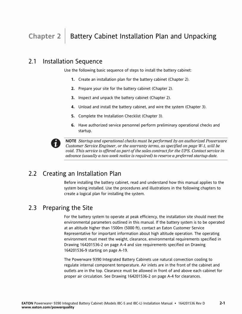
2.1 Installation Sequence
Use the following basic sequence of steps to install the battery cabinet:
1. Create an installation plan for the battery cabinet (Chapter 2).
2. Prepare your site for the battery cabinet (Chapter 2).
3. Inspect and unpack the battery cabinet (Chapter 2).
4. Unload and install the battery cabinet, and wire the system (Chapter 3).
5. Complete the Installation Checklist (Chapter 3).
6. Have authorized service personnel perform preliminary operational checks and
startup.
NOTE Startup and operational checks must be performed by an authorized Powerware
Customer Service Engineer, or the warranty terms, as specified on page W-1, will be
void. This service is offered as part of the sales contract for the UPS. Contact service in
advance (usually a two week notice is required) to reserve a preferred startup date.
2.2 Creating an Installation Plan
Before installing the battery cabinet, read and understand how this manual applies to the
system being installed. Use the procedures and illustrations in the following chapters to
create a logical plan for installing the system.
2.3 Preparing the Site
For the battery system to operate at peak efficiency, the installation site should meet the
environmental parameters outlined in this manual. If the battery system is to be operated
at an altitude higher than 1500m (5000 ft), contact an Eaton Customer Service
Representative for important information about high altitude operation. The operating
environment must meet the weight, clearance, environmental requirements specified in
Drawing 164201536-2 on page A-4 and size requirements specified on Drawing
164201536-9 starting on page A-19.
The Powerware 9390 Integrated Battery Cabinets use natural convection cooling to
regulate internal component temperature. Air inlets are in the front of the cabinet and
outlets are in the top. Clearance must be allowed in front of and above each cabinet for
proper air circulation. See Drawing 164201536-2 on page A-4 for clearances.

Battery Cabinet Installation Plan and Unpacking
2-2 EATON Powerware® 9390 Integrated Battery Cabinet (Models IBC-S and IBC-L) Installation Manual � 164201536 Rev D www.eaton.com/powerquality
2.3.1 Environment Considerations
The life of the battery system is adversely affected if the installation does not meet the
following guidelines:
A The system must be installed on a level floor suitable for computer or electronic
equipment.
A The system must be installed in a temperature and humidity controlled indoor area free
of conductive contaminants.
A The Environmental Monitoring Probe (EMP), for remote monitoring of battery
environmental conditions, must be installed and set up by an authorized Powerware
Customer Service Engineer, or the extended battery warranty terms specified on
page W-1 will be void.
Failure to follow guidelines may void your warranty.
2.3.2 Preparing for Wiring the Battery System
Power and control wiring for integral (line-up‐and‐match) battery cabinets are supplied
with the cabinets.
Wiring requirements for battery cabinets installed separate from the UPS cabinet, including
the minimum AWG size of external wiring, can be found on Drawing 164201536-5, Table D,
starting on page A-10. The power wiring connections for this equipment are rated at 90°C.
If wire is run in an ambient temperature greater than 30°C, higher temperature wire
and/or larger size wire may be necessary. Battery control wiring requirements can be found
on Drawing 164201536-8, starting on page A-17 and should be connected at the battery
interface terminal block located inside the battery cabinet.

Battery Cabinet Installation Plan and Unpacking
2-3EATON Powerware® 9390 Integrated Battery Cabinet (Models IBC-S and IBC-L) Installation Manual � 164201536 Rev Dwww.eaton.com/powerquality
2.4 Inspecting and Unpacking the Battery Cabinet
The next step is inspecting and unpacking the battery cabinet. The cabinet is shipped
bolted to a pallet consisting of four angle metal supports secured to two four-inch by
six-inch wood supports, as shown in Figure 2‐1, and protected with outer protective
packaging material.
Figure 2‐1. Powerware 9390 Battery Cabinet as Shipped on Pallet (Model IBC-L shown)

Battery Cabinet Installation Plan and Unpacking
2-4 EATON Powerware® 9390 Integrated Battery Cabinet (Models IBC-S and IBC-L) Installation Manual � 164201536 Rev D www.eaton.com/powerquality
C A U T I O NThe battery cabinet is extremely heavy (see Table A on page A-4). If unpacking instructions are
not closely followed, the cabinet may tip and cause serious injury.
1. Carefully inspect the outer packaging for evidence of damage during transit.
C A U T I O NDo not install a damaged cabinet. Report any damage to the carrier and contact an Eaton
Customer Service Representative immediately.
2. Use a forklift or pallet jack to move the packaged cabinet to the installation site,
or as close as possible, before unpacking. Insert the forklift or pallet jack's forks
between the pallet supports on the bottom of the unit.
NOTE Verify that the forklift or pallet jack is rated to handle the weight of the cabinet
(see Table A on page A-4 for cabinet weight).
C A U T I O NDo not tilt the battery cabinet more than 10° from vertical or cabinet may tip over.
3. Set the pallet on a firm, level surface, allowing a minimum clearance of 3m (10 ft)
on each side for removing the cabinet from the pallet.
4. Remove the protective covering from the cabinet.
5. Remove the packing materials, and discard or recycle them in a responsible
manner.
6. After removing the protective covering, inspect the contents for any evidence of
physical damage, and compare each item with the Bill of Lading. If damage has
occurred or shortages are evident, contact an Eaton Customer Service
Representative immediately to determine the extent of the damage and its impact
upon further installation.
NOTE While waiting for installation, protect the unpacked cabinet from moisture, dust,
and other harmful contaminants. Failure to store and protect the battery cabinet
properly may void your warranty.

3-1EATON Powerware® 9390 Integrated Battery Cabinet (Models IBC-S and IBC-L) Installation Manual � 164201536 Rev Dwww.eaton.com/powerquality
Chapter 3 Installing Battery Cabinets
3.1 Preliminary Installation Information
W A R N I N GThe installation of battery cabinets should be performed or supervised by personnel
knowledgeable of batteries and their associated precautions. Keep unauthorized personnel
away from battery cabinets.
Observe these precautions when working on or around battery cabinets:
A Remove watches, rings, or other metal objects.
A Use tools with insulated handles.
A Wear rubber gloves and boots.
A Do not lay tools or metal parts on top of batteries or battery cabinets.
Refer to the following while installing the battery system:
A See Appendix A for installation drawings and additional installation notes.
A Refer to the appropriate Powerware 9390 UPS Installation and Operation Manual, as
referenced in paragraph 1.6, for UPS cabinet conduit and terminal locations, and
terminal specifications.
A Dimensions in this manual are in millimeters and inches.
A Do not tilt the cabinets more than �10° during installation.
A The conduit landing plates are to be removed to add conduit landing holes as required.
Plate material is 16 gauge steel (1.5 mm/0.06� thick).
A The cabinets must be installed on a level floor suitable for computer or electronic
equipment.
A See Table A on page A-4 for equipment weight and point loading.
A Details about control wiring are provided in each procedure. Drawing 164201536-8
starting on page A-17 identifies the control wiring terminations.
A The Environmental Monitoring Probe, for remote monitoring of battery environmental
conditions, must be installed and setup by an authorized Powerware Customer Service
Engineer, or the extended battery warranty terms, as specified on page W-1, will be void.
A Once the battery cabinets are installed and wired, return to the appropriate Powerware
9390 UPS Installation and Operation Manual, as referenced in paragraph 1.6, to
complete the UPS wiring.

Installing Battery Cabinets
3-2 EATON Powerware® 9390 Integrated Battery Cabinet (Models IBC-S and IBC-L) Installation Manual � 164201536 Rev D www.eaton.com/powerquality
3.2 Unloading the Battery Cabinet from the Pallet
The battery cabinet is bolted to a pallet consisting of four angle metal supports secured to
two four-inch by six-inch wood supports.
1. Unfasten front door latch and swing doors open.
2. Remove doors. Remove the retaining screw located inside each door at the
bottom hinge pivot point, then lift the door off. Save the retaining screws for
reinstallation of the doors.
3. Locate the field kit (packed inside of the cabinet). Locate the four 1/2� jacking
bolts and install them in the threaded holes in the front and rear supports. Place a
floor protector underneath each jacking bolt, and screw the bolts down against
them. The floor protectors protect the floor from being marred by the jacking
bolts.
Floor Protector(Step 3)
Left-handDoor (Step 1)
4�6 Support
Front Support
4�6 SupportHardware (Step 4)
Jacking Bolt(Step 3)
Side Support
Cabinet SupportHardware (Step 9)
Figure 3‐1. Removing Shipping Supports
4. Loosen, but do not remove, the hardware holding the 4�6 supports to the front
and rear supports.
W A R N I N GSERIOUS INJURY MAY OCCUR. Battery cabinets are extremely heavy. If unloading instructions
are not closely followed, cabinet may tip.

Installing Battery Cabinets
3-3EATON Powerware® 9390 Integrated Battery Cabinet (Models IBC-S and IBC-L) Installation Manual � 164201536 Rev Dwww.eaton.com/powerquality
5. Turn each jacking bolt consecutively, two full turns, until the 4�6 supports clear
the floor by approximately 3 mm (1/8�).
W A R N I N GRISK OF INSTABILITY. Turning the jacking bolts unevenly may cause the cabinet to become
unbalanced. To prevent tipping the cabinet, raise and lower the jacking bolts evenly.
C A U T I O NCABINET MAY TIP. The battery cabinet should only be raised approximately 3 mm (1/8�)
above the floor (just enough to allow removal of the 4�6 supports).
6. After the 4�6 supports clear the floor, remove the hardware loosened in Step 4.
Pull the 4�6 supports out from under the battery cabinet. Please discard or
recycle them in a responsible manner.
C A U T I O NCABINET MAY FALL. Do not loosen the hardware attaching the side or front supports to the
cabinet base, or the front and side supports to each other, at this time. The cabinet must be
lowered by the jacking bolts before the supports can be removed.
7. Carefully and evenly lower the cabinet by turning each jacking bolt consecutively
two full turns (maximum) until the casters contact the floor, and the cabinet is no
longer supported by the jacking bolts.
8. After the battery cabinet is resting on the floor, remove the jacking bolts and
discard or recycle them in a responsible manner.
9. Remove the hardware holding the front, rear and side supports to the cabinet
base. Discard or recycle the hardware and support brackets in a responsible
manner.
10. The battery cabinet is now ready to be rolled to its final location.
11. Repeat Steps 2 through 10 for each cabinet you are preparing to install.
Installing Battery Cabinets
3-4 EATON Powerware® 9390 Integrated Battery Cabinet (Models IBC-S and IBC-L) Installation Manual � 164201536 Rev D www.eaton.com/powerquality
3.3 Model IBC-S Battery Cabinet Installation
The method used to install the battery cabinets depends on the type of installation being
undertaken.
Each battery cabinet can be installed as a line-up-and-match or standalone system. The
term line-up-and-match refers to battery cabinets that are physically attached to the UPS,
share internal wiring, and use the battery cabinet breaker as the battery isolation device.
The term standalone refers to battery cabinets that are not physically attached to the UPS,
are wired with external contractor-supplied wiring, and use a single overcurrent protection
and disconnect device located near the batteries.
A To install an line-up-and-match battery system, proceed to paragraph 3.3.1.
A To install a standalone battery system, proceed to paragraph 3.3.3.
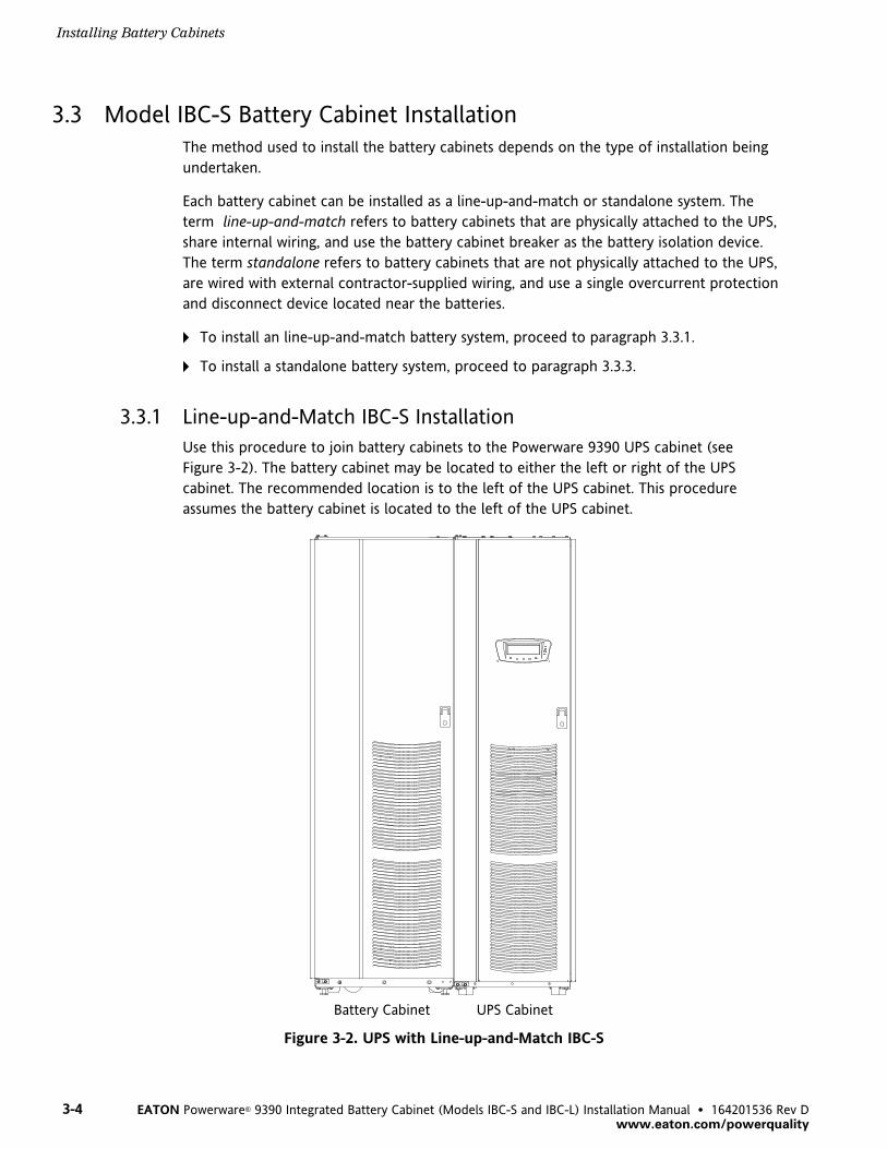
3.3.1 Line-up-and-Match IBC-S Installation
Use this procedure to join battery cabinets to the Powerware 9390 UPS cabinet (see
Figure 3‐2). The battery cabinet may be located to either the left or right of the UPS
cabinet. The recommended location is to the left of the UPS cabinet. This procedure
assumes the battery cabinet is located to the left of the UPS cabinet.
Battery Cabinet UPS Cabinet
Figure 3‐2. UPS with Line-up-and-Match IBC-S

Installing Battery Cabinets
3-5EATON Powerware® 9390 Integrated Battery Cabinet (Models IBC-S and IBC-L) Installation Manual � 164201536 Rev Dwww.eaton.com/powerquality
1. Verify that the UPS is properly installed and secured. Refer to the appropriate
Powerware 9390 UPS Installation and Operation Manual, as referenced in
paragraph 1.6, for installation instructions.
2. Roll the battery cabinet to an area near the left‐hand side of the UPS, as shown in
Figure 3‐3.
3. Remove the field kit. The field kit is attached with cable ties to the frame inside
the door. Retain the field kit for later use.
NOTE When a line-up-and-match UPS system is ordered together with battery cabinets,
the first battery cabinet is supplied with two cosmetic covers. The UPS cabinet,
additional battery cabinets, and other ancillary cabinets are supplied without cosmetic
covers.
NOTE When cabinets are properly aligned, all cabinet doors are flush.
Screws from Kit
Bracketfrom Kit
Battery CabinetUPS Cabinet
Large Bracket(See Figure 3‐4)
Top View with Small Bracket
Figure 3‐3. UPS to IBC-S Joining Brackets
4. If necessary, remove the cosmetic cover and hanger brackets from the left‐hand
side of the UPS. Save cover, screws, and brackets for later use.
5. If necessary, remove the cosmetic cover and hanger brackets from the right‐hand
side of the battery cabinet. Save cover, screws, and brackets for later use.
6. Remove the knockout plug on the bottom left side of the UPS cabinet inside
panel. Refer to Appendix A of the appropriate Powerware 9390 UPS Installation
and Operation Manual, as referenced in paragraph 1.6, for the location of the
knockout plug.
Installing Battery Cabinets
3-6 EATON Powerware® 9390 Integrated Battery Cabinet (Models IBC-S and IBC-L) Installation Manual � 164201536 Rev D www.eaton.com/powerquality
7. Install nylon grommet from field kit around hole left after removal of knockout
plug.
8. Push the battery cabinet toward the UPS cabinet until the doors are flush with
each other.
9. Secure the battery cabinet position by lowering the leveling feet until cabinet is
not resting on the casters. Ensure the cabinet is level and matches the height of
the installed UPS cabinet.
NOTE Two cabinet joining brackets are provided in the field kit for securing each
cabinet at the top and bottom. A small flat bracket joins the top of the cabinets, and a
larger angle bracket joins the cabinets at the bottom. The small flat bracket is attached
to the cabinet tops first.
10. Locate the small flat bracket from the field kit. Align the holes in the small flat
bracket over the two holes in the top front of the cabinets. Secure the bracket to
the cabinets with screws from the field kit (see Figure 3‐3).
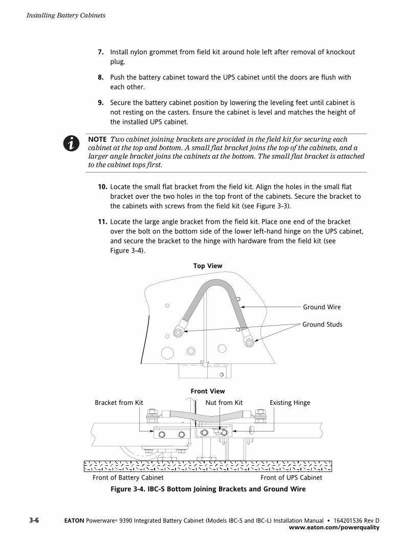
11. Locate the large angle bracket from the field kit. Place one end of the bracket
over the bolt on the bottom side of the lower left‐hand hinge on the UPS cabinet,
and secure the bracket to the hinge with hardware from the field kit (see
Figure 3‐4).
ÒÒÒÒÒÒÒÒÒÒÒÒÒÒÒÒÒÒÒÒÒÒÒÒÒÒÒÒÒÒÒÒÒÒÒÒÒÒÒÒÒÒÒÒÒÒÒÒ
Top View
Ground Wire
Ground Studs
Bracket from Kit Existing Hinge
Front of Battery Cabinet Front of UPS Cabinet
Front View
Nut from Kit
Figure 3‐4. IBC-S Bottom Joining Brackets and Ground Wire

Installing Battery Cabinets
3-7EATON Powerware® 9390 Integrated Battery Cabinet (Models IBC-S and IBC-L) Installation Manual � 164201536 Rev Dwww.eaton.com/powerquality
12. Align the holes in the other end of the bracket with the holes in the bottom
right-hand side of the battery cabinet (see Figure 3‐4). Secure the bracket with
hardware from the field kit.
13. Route the ground wire (from the field kit) from the ground stud in the battery
cabinet, under the lower right‐hand battery tray, through the access hole in the
side panel of the UPS, and attach to the ground stud in the UPS cabinet (see
Figure 3‐4). Hardware is provided on each ground stud.
14. If installing additional battery cabinets, repeat Steps 2 through 13 to join each
additional battery cabinet; otherwise, proceed to Step 15.
15. If not already installed, mount the hanger brackets to the top left side of the last
battery cabinet using M4 screws (see Figure 3‐5).
16. If not already installed, hang the side panel on the hanger brackets and align with
the front and rear of the battery cabinet.
17. If not already secured, secure the side panel at the bottom using M4 hex-head
screws previously removed.
18. Proceed to paragraph 3.3.2.
Hanger Bracket Location(Secured with Screws)
Cabinet-to-CabinetCable Access Area(Each Side)
Figure 3‐5. IBC-S Hanger Brackets

Installing Battery Cabinets
3-8 EATON Powerware® 9390 Integrated Battery Cabinet (Models IBC-S and IBC-L) Installation Manual � 164201536 Rev D www.eaton.com/powerquality
3.3.2 Line-up-and-Match IBC-S Electrical Connections
Use this procedure to wire an line-up-and-match battery cabinet to the Powerware 9390
UPS cabinet. All battery cabinets arrive at the site with each battery connection string
electrically disconnected. If you are installing more than one battery cabinet, the battery
cabinet adjacent to the UPS will be the only cabinet directly connected to the UPS.
D A N G E RLETHAL VOLTAGE is present when performing the remaining steps in this section and
subsequent sections.
1. Locate the battery cabinet-to-battery cabinet breaker sensing cable in the first
battery cabinet. Route this connector into the cabinet to the immediate left and
mate with the matching connector in that cabinet (see Drawing 164201536-8 on
page A-17).
2. If installing multiple battery cabinets, proceed to Step 3; otherwise, proceed to
Step 5.
3. On first and middle battery cabinet TB1 terminal boards, disconnect jumper from
terminal 4 and connect to terminal 5. On last battery cabinet TB1 terminal board,
verify jumper is connected between terminals 4 and 10. See Drawings 164201536-3
and 164201536-8.
4. Proceed to Step 6.
5. On battery cabinet TB1 terminal board, verify jumper is connected between
terminals 4 and 10. See Drawings 164201536-3 and 164201536-8.
6. Locate the battery wiring harness in the first battery cabinet. Route this harness
into the cabinet to the immediate left and connect the (+) lead to the (+) battery
terminal and the (–) lead to the (–) battery terminal (see Drawing 164201536-7
starting on page A-14). Use pressure and bus bar terminations, as necessary, for
connecting cables between the battery cabinets.
7. Repeat Steps 1 through 6 for each battery cabinet, and then proceed to Step 8.
8. Locate the UPS-to-battery cabinet breaker sensing cable inside the first battery
cabinet. Mate the connector on this cable with the matching connector in the
cabinet (see Drawing 164201536-8 on page A-17). Route the other end of this
cable into the UPS cabinet and connect to terminal strip TB2. Refer to the
appropriate Powerware 9390 UPS Installation and Operation Manual, as referenced
in paragraph 1.6, for UPS cabinet terminal locations.

Installing Battery Cabinets
3-9EATON Powerware® 9390 Integrated Battery Cabinet (Models IBC-S and IBC-L) Installation Manual � 164201536 Rev Dwww.eaton.com/powerquality
9. A UPS‐to‐battery wiring harness is supplied inside the first battery cabinet. Use
pressure and bus bar terminations, as necessary, for connecting cables between
the UPS and battery cabinet. Connect and route cables from positive (+) and
negative (–) terminals in the the first battery cabinet into the UPS cabinet. Connect
the (+) lead to terminal E4 (+) and the (–) to terminal E5 (–) in the UPS cabinet.
Refer to the appropriate Powerware 9390 UPS Installation and Operation Manual,
as referenced in paragraph 1.6, for UPS cabinet terminal locations.
10. Verify that all battery breakers are in the OFF position.
11. Connect the string of battery trays by mating the loose red connector from each
tray to the fixed black connector mounted on the front edge of the tray above.
Connect the top and bottom tray connectors to the mating cabinet connectors to
complete the battery string connections (see Figure 3‐6).
12. Repeat Step 10 for each battery cabinet, and then proceed to Step 13.
13. Replace the doors that were removed in paragraph 3.2.
14. Secure all battery cabinets by closing and latching the doors.
15. Once the battery cabinets are installed and wired, return to the appropriate
Powerware 9390 UPS Installation and Operation Manual, as referenced in
paragraph 1.6, to complete the UPS wiring.
Battery Breaker
Fixed Right BatteryPower Connector(Black)
String Connectors(Red)
Figure 3‐6. IBC-S Battery String Connection

Installing Battery Cabinets
3-10 EATON Powerware® 9390 Integrated Battery Cabinet (Models IBC-S and IBC-L) Installation Manual � 164201536 Rev D www.eaton.com/powerquality
3.3.3 Standalone IBC-S Installation
Use this procedure to install a standalone battery cabinet (see Figure 3‐7).
UPS Cabinet Battery Cabinet
Figure 3‐7. UPS with Standalone IBC-S
1. Verify that the UPS is properly installed and secured. Refer to the appropriate
Powerware 9390 UPS Installation and Operation Manual, as referenced in
paragraph 1.6, for installation instructions.
2. Roll the battery cabinet to the area where the battery cabinet is to be installed.
3. Secure the battery cabinet in position by lowering the leveling feet until cabinet is
not resting on the casters and the cabinet is level.
4. Remove the field kit. The field kit is attached with cable ties to the frame inside
the door. Retain the field kit for later use.
5. If installing more than one battery cabinet, proceed to Step 6; otherwise, proceed
to paragraph 3.3.4.
NOTE When a UPS system is ordered together with battery cabinets for standalone
installation, the first battery cabinet is supplied with two cosmetic covers. Additional
battery cabinets are supplied without cosmetic covers. Cosmetic covers must be ordered
for the UPS cabinet and/or other ancillary cabinets.

Installing Battery Cabinets
3-11EATON Powerware® 9390 Integrated Battery Cabinet (Models IBC-S and IBC-L) Installation Manual � 164201536 Rev Dwww.eaton.com/powerquality
6. Remove the cosmetic cover and hanger brackets from the appropriate side or
sides of the battery cabinets, depending on the position of the cabinets. Save
covers, screws, and brackets for later use.
7. Roll the next battery cabinet to be joined to an area near the appropriate side of
the first battery cabinet.
8. Push the battery cabinet to be joined towards the first battery cabinet until the
doors are flush with each other.
9. Secure the battery cabinet position by lowering the leveling feet until cabinet is
not resting on the casters. Ensure the cabinet is level and matches the height of
the first installed battery cabinet.
NOTE Two cabinet joining brackets are provided in the field kit for securing each
cabinet at the top and bottom. A small flat bracket joins the top of the cabinets, and a
larger angle bracket joins the cabinets at the bottom. The flat bracket is attached to the
cabinet tops first.
10. Locate the small flat bracket from the field kit. Align the holes in the flat bracket
over the two holes in the top front of the cabinets. Secure the bracket to the
cabinets with screws from the field kit (see Figure 3‐3).
11. Locate the large angle bracket from the field kit. Place one end of the bracket
over the bolt on the bottom side of the lower left‐hand hinge on the adjacent
battery cabinet, and secure the bracket to the hinge with hardware from the field
kit (see Figure 3‐4).
12. Align the holes in the other end of the bracket with the holes in the bottom
right-hand side of the next battery cabinet (see Figure 3‐4). Secure the bracket
with hardware from the field kit.
13. Route the ground wire (from the field kit) from the ground stud in one battery
cabinet, under the lower battery tray and through the cabinet-to-cabinet cable
access area in the side of the cabinets, and attach to the ground stud in the other
battery cabinet (see Figure 3‐4 and Figure 3‐5). Hardware is provided on each
ground stud.
14. If installing additional battery cabinets, repeat Steps 6 through 13 to join each
additional battery cabinet; otherwise, proceed to Step 15.
15. If not already installed, mount the hanger brackets to the top appropriate side of
the last battery cabinet using M4 screws (see Figure 3‐5).
16. If not already installed, hang the side panel on the hanger brackets and align with
the front and rear of the battery cabinet.
17. If not already secured, secure the side panel at the bottom using M4 hex-head
screws previously removed.
18. Proceed to paragraph 3.3.4.

Installing Battery Cabinets
3-12 EATON Powerware® 9390 Integrated Battery Cabinet (Models IBC-S and IBC-L) Installation Manual � 164201536 Rev D www.eaton.com/powerquality
3.3.4 Standalone IBC-S Electrical Connections
Use this procedure to wire a standalone battery cabinet to the Powerware 9390 UPS
cabinet. All battery cabinets arrive at the site with each battery connection string
electrically disconnected. If you are installing more than one battery cabinet, the first
battery cabinet will be the only cabinet directly connected to the UPS.
D A N G E RLETHAL VOLTAGE is present when performing the remaining steps in this section and
subsequent sections.
1. Locate the battery breaker sensing cable in the right‐hand battery cabinet. Route
this connector into the cabinet to the immediate left and mate with the matching
connector in that cabinet (see Drawing 164201536-8 on page A-17).
2. If installing multiple battery cabinets, proceed to Step 3; otherwise, proceed to
Step 5.
3. On first and middle battery cabinet TB1 terminal boards, disconnect jumper from
terminal 4 and connect to terminal 5. On last battery cabinet TB1 terminal board,
verify jumper is connected between terminals 4 and 10. See Drawings 164201536-3
and 164201536-8.
4. Proceed to Step 6.
5. On battery cabinet TB1 terminal board, verify jumper is connected between
terminals 4 and 10. See Drawings 164201536-3 and 164201536-8.
6. Locate the battery wiring harness in the first battery cabinet. Route this harness
into the next cabinet and connect the (+) lead to the (+) battery terminal and the
(–) lead to the (–) battery terminal (see Drawing 164201536-7 on page A-14). Use
pressure and bus bar terminations, as necessary, for connecting cables between
the battery cabinets.
7. Repeat Steps 1 through 6 for each battery cabinet, and then proceed to Step 8.
8. Refer to the following to connect the external wiring from the first battery cabinet
to the UPS cabinet:
a. See Drawing 164201536-5 on page A-9 to size wire for connecting the battery
cabinets to the remotely located UPS cabinet.
b. See Drawing 164201536-6 starting on page A-12 for battery cabinet top or
bottom conduit landing locations.
c. See Drawing 164201536-7 on page A-14 for location of positive (+) and
negative (–) terminals.
d. Refer to the appropriate Powerware 9390 UPS Installation and Operation
Manual, as referenced in paragraph 1.6, for top or bottom conduit landing
locations.

Installing Battery Cabinets
3-13EATON Powerware® 9390 Integrated Battery Cabinet (Models IBC-S and IBC-L) Installation Manual � 164201536 Rev Dwww.eaton.com/powerquality
9. Locate the UPS-to-battery cabinet breaker sensing cable inside the first battery
cabinet. Mate the connector on this cable with the matching connector in the
cabinet (see Drawing 164201536-8 on page A-17). Route the other end of this
cable through conduit (top or bottom entry) to UPS cabinet and connect to
terminal strip TB2. Refer to the appropriate Powerware 9390 UPS Installation and
Operation Manual, as referenced in paragraph 1.6, for UPS cabinet terminal
locations.
10. Use pressure and bus bar terminations, as necessary, for connecting cables
between the UPS and battery cabinet. Connect and route cables from positive (+)
and negative (–) terminals in the first battery cabinet through conduit (top or
bottom entry) to UPS cabinet terminals E4 and E5.
11. Verify that all battery breakers are in the OFF position.
12. Connect the string of battery trays by mating the loose red connector from each
tray to the fixed black connector mounted on the front edge of the tray above.
Connect the top and bottom tray connectors to the mating cabinet connectors to
complete the battery string connections (see Figure 3‐6).
13. Repeat Step 11 for each battery cabinet, and then proceed to Step 14.
14. Replace the doors that were removed in paragraph 3.2.
15. Secure all battery cabinets by closing and latching the doors.
16. Once the battery cabinets are installed and wired, return to the appropriate
Powerware 9390 UPS Installation and Operation Manual, as referenced in
paragraph 1.6, to complete the UPS wiring.
3.4 Model IBC-L Battery Cabinet Installation
The method used to install the battery cabinets depends on the type of installation being
undertaken.
Each battery cabinet can be installed as a line-up-and-match or standalone system. The
term line-up-and-match refers to battery cabinets that are physically attached to the UPS,
share internal wiring, and use the battery cabinet breaker as the battery isolation device.
The term standalone refers to battery cabinets that are not physically attached to the UPS,
are wired with external contractor-supplied wiring, and use a single overcurrent protection
and disconnect device located near the batteries.
A To install an line-up-and-match battery system, proceed to paragraph 3.4.1.
A To install a standalone battery system, proceed to paragraph 3.4.3.

Installing Battery Cabinets
3-14 EATON Powerware® 9390 Integrated Battery Cabinet (Models IBC-S and IBC-L) Installation Manual � 164201536 Rev D www.eaton.com/powerquality
3.4.1 Line-up-and-Match IBC-L Installation
Use this procedure to join battery cabinets to the Powerware 9390 UPS cabinet (see
Figure 3‐8). The battery cabinet may be located to either the left or right of the UPS
cabinet. The recommended location is to the left of the UPS cabinet. This procedure
assumes the battery cabinet is located to the left of the UPS cabinet.
Battery Cabinet UPS Cabinet
Figure 3‐8. UPS with Line-up-and-Match IBC-L
1. Verify that the UPS is properly installed and secured. Refer to the appropriate
Powerware 9390 UPS Installation and Operation Manual, as referenced in
paragraph 1.6, for installation instructions.
2. Roll the battery cabinet to an area near the left‐hand side of the UPS, as shown in
Figure 3‐9.
3. Remove the field kit. The field kit is attached with cable ties to the frame inside
the door. Retain the field kit for later use.
NOTE When a line-up-and-match UPS system is ordered together with battery cabinets,
the first battery cabinet is supplied with two cosmetic covers. The UPS cabinet,
additional battery cabinets, and other ancillary cabinets are supplied without cosmetic
covers.

Installing Battery Cabinets
3-15EATON Powerware® 9390 Integrated Battery Cabinet (Models IBC-S and IBC-L) Installation Manual � 164201536 Rev Dwww.eaton.com/powerquality
NOTE When cabinets are properly aligned, all cabinet doors are flush.
Bracketfrom Kit
Existing Screws
Top View with Small Bracket
Battery CabinetUPS Cabinet
Large Bracket(See Figure 3‐10)
Figure 3‐9. UPS to IBC-L Joining Brackets
4. If necessary, remove the cosmetic cover and hanger brackets from the left‐hand
side of the UPS. Save cover, screws, and brackets for later use.
5. If necessary, remove the cosmetic cover and hanger brackets from the right‐hand
side of the battery cabinet. Save cover, screws, and brackets for later use.
6. Remove the knockout plug on the bottom left side of the UPS cabinet inside
panel. Refer to Appendix A of the appropriate Powerware 9390 UPS Installation
and Operation Manual, as referenced in paragraph 1.6, for the location of the
knockout plugs.
7. Install the nylon grommet from the field kit around hole left after removal of
knockout plug.
8. Push the battery cabinet toward the UPS cabinet until the doors are flush with
each other.
9. Secure the battery cabinet position by lowering the leveling feet until cabinet is
not resting on the casters. Ensure the cabinet is level and matches the height of
the installed UPS cabinet.

Installing Battery Cabinets
3-16 EATON Powerware® 9390 Integrated Battery Cabinet (Models IBC-S and IBC-L) Installation Manual � 164201536 Rev D www.eaton.com/powerquality
NOTE Two cabinet joining brackets are provided in the field kit for securing each
cabinet at the top and bottom. A small flat bracket joins the top of the cabinets and a
larger flat bracket joins the cabinets at the bottom. The small flat bracket is attached to
the cabinet tops first.
10. Remove the left‐hand screw from the top door hinge of the UPS cabinet and the
right-hand screw from the top right door hinge of the battery cabinet.
11. Locate the small flat bracket from the field kit. Align the holes in the small flat
bracket over the door hinge screw holes. Replace the screws in the hinges,
securing the bracket to the cabinets (see Figure 3‐9).
12. Locate the large flat bracket from the field kit. Place one end of the bracket over
the bolt on the bottom side of the lower right‐hand hinge on the battery cabinet
and the other end over the bolt on the bottom side of the lower left‐hand hinge
on the UPS cabinet (see Figure 3‐10).
Top View
Ground Wire
Ground Studs
ÒÒÒÒÒÒÒÒÒÒÒÒÒÒÒÒÒÒÒÒÒÒÒÒÒÒÒÒÒÒÒÒÒÒÒÒÒÒÒÒÒÒÒÒÒÒÒÒÒÒ
Existing Hinge Existing Hinge
Front of Battery Cabinet Front of UPS Cabinet
Front View
Bracket from Kit
Nuts from Kit
Figure 3‐10. IBC-L Bottom Joining Brackets and Ground Wire

Installing Battery Cabinets
3-17EATON Powerware® 9390 Integrated Battery Cabinet (Models IBC-S and IBC-L) Installation Manual � 164201536 Rev Dwww.eaton.com/powerquality
13. Secure the bracket to the hinges with hardware from the field kit.
14. Route the ground wire (from the field kit) from the ground stud in the battery
cabinet, under the lower right‐hand battery tray, through the access hole in the
side panel of the UPS, and attach to the ground stud in the UPS cabinet (see
Figure 3‐10). Hardware is provided on each ground stud.
15. If installing additional battery cabinets, repeat Steps 2 through 13 to join each
additional battery cabinet; otherwise, proceed to Step 15.
16. If not already installed, mount the hanger brackets to the top left side of the last
battery cabinet using M4 screws (see Figure 3‐11).
17. If not already installed, hang the side panel on the hanger brackets and align with
the front and rear of the battery cabinet.
18. If not already secured, secure the side panel at the bottom using M4 hex-head
screws previously removed.
19. Proceed to paragraph 3.4.2.
Hanger Bracket Location(Secured with Screws)
Cabinet-to-CabinetCable Access Area(Each Side)
Figure 3‐11. IBC-L Battery Cabinet Hanger Brackets

Installing Battery Cabinets
3-18 EATON Powerware® 9390 Integrated Battery Cabinet (Models IBC-S and IBC-L) Installation Manual � 164201536 Rev D www.eaton.com/powerquality
3.4.2 Line-up-and-Match IBC-L Electrical Connections
Use this procedure to wire an line-up-and-match battery cabinet to the Powerware 9390
UPS cabinet. All battery cabinets arrive at the site with each battery connection string
electrically disconnected. If you are installing more than one battery cabinet, the battery
cabinet adjacent to the UPS will be the only cabinet directly connected to the UPS.
D A N G E RLETHAL VOLTAGE is present when performing the remaining steps in this section and
subsequent sections.
1. Locate the battery cabinet-to-battery cabinet breaker sensing cable in the first
battery cabinet. Route this connector into the cabinet to the immediate left and
mate with the matching connector in that cabinet (see Drawing 164201536-8 on
page A-17).
2. If installing multiple battery cabinets, proceed to Step 3; otherwise, proceed to
Step 5.
3. On first and middle battery cabinet TB1 terminal boards, disconnect jumper from
terminal 4 and connect to terminal 5. On last battery cabinet TB1 terminal board,
verify jumper is connected between terminals 4 and 10. See Drawings 164201536-3
and 164201536-8.
4. Proceed to Step 6.
5. On battery cabinet TB1 terminal board, verify jumper is connected between
terminals 4 and 10. See Drawings 164201536-3 and 164201536-8.
6. Locate the battery wiring harness under the bottom tray in the first battery
cabinet. Route this harness into the cabinet to the immediate left and connect the
(+) lead to the (+) battery terminal and the (–) lead to the (–) battery terminal
(see Drawing 164201536-7 starting on page A-14). Use pressure and bus bar
terminations, as necessary, for connecting cables between the battery cabinets.
7. Repeat Steps 1 through 6 for each battery cabinet, and then proceed to Step 8.
8. Locate the UPS-to-battery cabinet breaker sensing cable inside the first battery
cabinet. Mate the connector on this cable with the matching connector in the
cabinet (see Drawing 164201536-8 on page A-17). Route the other end of this
cable into the UPS cabinet and connect to terminal strip TB2. Refer to the
appropriate Powerware 9390 UPS Installation and Operation Manual, as referenced
in paragraph 1.6, for UPS cabinet terminal locations.

Installing Battery Cabinets
3-19EATON Powerware® 9390 Integrated Battery Cabinet (Models IBC-S and IBC-L) Installation Manual � 164201536 Rev Dwww.eaton.com/powerquality
9. A UPS‐to‐battery wiring harness is supplied inside the first battery cabinet. Use
pressure and bus bar terminations, as necessary, for connecting cables between
the UPS and battery cabinet. Connect and route cables from positive (+) and
negative (–) terminals in the bottom of the first battery cabinet into the UPS
cabinet. Connect the (+) lead to terminal E4 (+) and the (–) to terminal E5 (–) in
the UPS cabinet. Refer to the appropriate Powerware 9390 UPS Installation and
Operation Manual, as referenced in paragraph 1.6, for UPS cabinet terminal
locations.
10. Verify that all battery breakers are in the OFF position.
11. Connect the string of battery trays by mating the loose red connector from each
tray to the fixed black connector mounted on the front edge of the tray above.
Connect the top and bottom tray connectors to the mating cabinet connectors to
complete the battery string connections (see Figure 3‐6).
12. Repeat Step 10 for each battery cabinet, and then proceed to Step 13.
13. Replace the doors that were removed in paragraph 3.2.
14. Secure all battery cabinets by closing and latching the doors.
15. Once the battery cabinets are installed and wired, return to the appropriate
Powerware 9390 UPS Installation and Operation Manual, as referenced in
paragraph 1.6, to complete the UPS wiring.
Battery Breaker
Fixed Right BatteryPower Connector(Black)
String Connectors(Red)
Figure 3‐12. IBC-L Battery String Connection

Installing Battery Cabinets
3-20 EATON Powerware® 9390 Integrated Battery Cabinet (Models IBC-S and IBC-L) Installation Manual � 164201536 Rev D www.eaton.com/powerquality
3.4.3 Standalone IBC-L Installation
Use this procedure to install a standalone battery cabinet (see Figure 3‐13).
UPS Cabinet Battery Cabinet
Figure 3‐13. UPS with Standalone IBC-L
1. Verify that the UPS is properly installed and secured. Refer to the appropriate
Powerware 9390 UPS Installation and Operation Manual, as referenced in
paragraph 1.6, for installation instructions.
2. Roll the battery cabinet to the area where the battery cabinet is to be installed.
3. Secure the battery cabinet position by lowering the leveling feet until cabinet is
not resting on the casters and the cabinet is level.
4. Remove the field kit. The field kit is attached with cable ties to the frame inside
the door. Retain the field kit for later use.
5. If installing more than one battery cabinet, proceed to Step 6; otherwise, proceed
to paragraph 3.4.4.
NOTE When a UPS system is ordered together with battery cabinets for standalone
(remote) installation, the first battery cabinet is supplied with two cosmetic covers.
Additional battery cabinets are supplied without cosmetic covers. Cosmetic covers must
be ordered for the UPS cabinet and/or other ancillary cabinets.

Installing Battery Cabinets
3-21EATON Powerware® 9390 Integrated Battery Cabinet (Models IBC-S and IBC-L) Installation Manual � 164201536 Rev Dwww.eaton.com/powerquality
6. Remove the cosmetic cover and hanger brackets from the appropriate side or
sides of the battery cabinets, depending on the position of the cabinets. Save
covers, screws, and brackets for later use.
7. Roll the next battery cabinet to be joined to an area near the appropriate side of
the first battery cabinet.
8. Push the battery cabinet to be joined towards the first battery cabinet until the
doors are flush with each other.
9. Secure the battery cabinet position by lowering the leveling feet until the cabinet
is not resting on the casters. Ensure the cabinet is level and matches the height of
the first installed battery cabinet.
NOTE Two cabinet joining brackets are provided for securing each cabinet at the top
and bottom. A flat bracket joins the top of the cabinets and a larger flat bracket joins
the cabinets at the bottom. The small flat bracket is attached to the cabinet tops first.
10. Remove the left‐hand and right-hand screws from the adjacent top door hinges of
the battery cabinets.
11. Locate the small flat bracket from the field kit. Align the holes in the small flat
bracket over the hinge screw holes. Replace the screws in the hinges, securing the
bracket to the cabinets (see Figure 3‐9).
12. Locate the large flat bracket from the field kit. Place the bracket over the bolts on
the bottom side of the adjacent lower hinges on the battery cabinets (see
Figure 3‐10).
13. Secure the bracket to the hinges with hardware from the field kit.
14. Route the ground wire (from the field kit) from the ground stud in one battery
cabinet, under the lower battery tray and through the cabinet-to-cabinet cable
access area in the side of the cabinets, and attach to the ground stud in the other
battery cabinet (see Figure 3‐10 and Figure 3‐11). Hardware is provided on each
ground stud.
15. If installing additional battery cabinets, repeat Steps 6 through 13 to join each
additional battery cabinet; otherwise, proceed to Step 15.
16. If not already installed, mount the hanger brackets to the top appropriate side of
the last battery cabinet using M4 screws (see Figure 3‐5).
17. If not already installed, hang the side panel on the hanger brackets and align with
the front and rear of the battery cabinet.
18. If not already secured, secure the side panel at the bottom using M4 hex-head
screws previously removed.
19. Proceed to paragraph 3.4.4.

Installing Battery Cabinets
3-22 EATON Powerware® 9390 Integrated Battery Cabinet (Models IBC-S and IBC-L) Installation Manual � 164201536 Rev D www.eaton.com/powerquality
3.4.4 Standalone Battery Cabinet Electrical Connections
Use this procedure to wire a standalone battery cabinet to the Powerware 9390 UPS
cabinet. All battery cabinets arrive at the site with each battery connection string
electrically disconnected. If you are installing more than one battery cabinet, the first
battery cabinet will be the only cabinet directly connected to the UPS.
D A N G E RLETHAL VOLTAGE is present when performing the remaining steps in this section and
subsequent sections.
1. Locate the battery breaker sensing cable in the right‐hand battery cabinet. Route
this connector into the cabinet to the immediate left and mate with the matching
connector in that cabinet (see Drawing 164201536-8 on page A-17).
2. If installing multiple battery cabinets, proceed to Step 3; otherwise, proceed to
Step 5.
3. On first and middle battery cabinet TB1 terminal boards, disconnect jumper from
terminal 4 and connect to terminal 5. On last battery cabinet TB1 terminal board,
verify jumper is connected between terminals 4 and 10. See Drawings 164201536-3
and 164201536-8.
4. Proceed to Step 6.
5. On battery cabinet TB1 terminal board, verify jumper is connected between
terminals 4 and 10. See Drawings 164201536-3 and 164201536-8.
6. Locate the battery wiring harness under the bottom tray in the right‐hand battery
cabinet. Route this harness into the cabinet to the immediate left and connect the
(+) lead to the (+) battery terminal and the (–) lead to the (–) battery terminal
(see Drawing 164201536-7 starting on page A-14). Use pressure and bus bar
terminations, as necessary, for connecting cables between the battery cabinets.
7. Repeat Steps 1 through 6 for each battery cabinet, and then proceed to Step 8.
8. Refer to the following to connect the external wiring from the first battery cabinet
to the UPS cabinet:
a. See Drawing 164201536-5 on page A-9 to size wire for connecting the battery
cabinets to the remotely located UPS cabinet.
b. See Drawing 164201536-6 starting on page A-12 for battery cabinet top or
bottom conduit landing locations.
c. See Drawing 164201536-7 on page A-14 for location of positive (+) and
negative (–) terminals.
d. Refer to the appropriate Powerware 9390 UPS Installation and Operation
Manual, as referenced in paragraph 1.6, for top or bottom conduit landing
locations.

Installing Battery Cabinets
3-23EATON Powerware® 9390 Integrated Battery Cabinet (Models IBC-S and IBC-L) Installation Manual � 164201536 Rev Dwww.eaton.com/powerquality
9. Locate the UPS-to-battery cabinet breaker sensing cable inside the first battery
cabinet. Mate the connector on this cable with the matching connector in the
cabinet (see Drawing 164201536-8 on page A-17). Route the other end of this
cable through conduit (top or bottom entry) to UPS cabinet and connect to
terminal strip TB2. Refer to the appropriate Powerware 9390 UPS Installation and
Operation Manual, as referenced in paragraph 1.6, for UPS cabinet terminal
locations.
10. Use pressure and bus bar terminations, as necessary, for connecting cables
between the UPS and battery cabinet. Connect and route cables from positive (+)
and negative (–) terminals in the bottom of the first battery cabinet through
conduit (top or bottom entry) to UPS cabinet terminals E4 and E5.
11. Verify that all battery breakers are in the OFF position.
12. Connect the string of battery trays by mating the loose red connector from each
tray to the fixed black connector mounted on the front edge of the tray above.
Connect the top and bottom tray connectors to the mating cabinet connectors to
complete the battery string connections (see Figure 3‐6).
13. Repeat Step 11 for each battery cabinet, and then proceed to Step 14.
14. Replace the doors that were removed in paragraph 3.2.
15. Secure all battery cabinets by closing and latching the doors.
16. After the battery cabinets are installed and wired, return to the appropriate
Powerware 9390 UPS Installation and Operation Manual, as referenced in
paragraph 1.6, to complete the UPS wiring.

Installing Battery Cabinets
3-24 EATON Powerware® 9390 Integrated Battery Cabinet (Models IBC-S and IBC-L) Installation Manual � 164201536 Rev D www.eaton.com/powerquality
3.5 Completing the Installation Checklist
The final step in installing your battery cabinet is to complete the Installation Checklist.
This checklist ensures that you have installed all hardware, cables, and other equipment.
Completing all items on the checklist will ensure a smooth installation. Make a copy of the
Installation Checklist before filling it out, and retain the original.
After completing your installation, a service representative will be able to verify the
operation of your battery cabinet, and commission it to support your critical load. The
service representative cannot perform any installation tasks other than verifying that the
battery cabinet has been correctly installed. Service personnel may request a copy of the
completed Installation Checklist to be sure you have completed all applicable equipment
installation requirements.
NOTE The Installation Checklist MUST be completed prior to starting the UPS system
for the first time.
Installation Checklist
� All packing materials and restraints have been removed from each cabinet.
� Each cabinet in the battery system is placed in its correct location.
� All cabinets are bolted together.
� A ground wire is installed between all cabinets that are bolted together.
� All conduits and cables are properly routed to the battery cabinets.
� A ground conductor is properly installed.
� Battery cables and harness are terminated on the E4 and E5 terminals in the UPS cabinet.
� Internal battery cabinet connections have been completed (cables, plugs, etc.).
� The EMP is installed and setup by an authorized Powerware Customer Service Engineer.
� Air conditioning equipment is installed and operating correctly.
� The area around the installed battery system is clean and dust‐free. (It is recommended that the battery
cabinet be installed on a sealed concrete pad or a sealed concrete floor.)
� Adequate working area exists around the battery cabinet and other cabinets.
� Adequate lighting is provided around all battery cabinet equipment.
� A remote battery disconnect control is mounted in its installed location and its wiring is terminated inside
the battery cabinet (OPTIONAL).

Installing Battery Cabinets
3-25EATON Powerware® 9390 Integrated Battery Cabinet (Models IBC-S and IBC-L) Installation Manual � 164201536 Rev Dwww.eaton.com/powerquality
Notes
_________________________________________________________________________
_________________________________________________________________________
_________________________________________________________________________
_________________________________________________________________________
_________________________________________________________________________
_________________________________________________________________________
_________________________________________________________________________
_________________________________________________________________________
_________________________________________________________________________
_________________________________________________________________________
_________________________________________________________________________
_________________________________________________________________________
_________________________________________________________________________
_________________________________________________________________________
_________________________________________________________________________
_________________________________________________________________________

Installing Battery Cabinets
3-26 EATON Powerware® 9390 Integrated Battery Cabinet (Models IBC-S and IBC-L) Installation Manual � 164201536 Rev D www.eaton.com/powerquality
This page intentionally left blank.

A-1EATON Powerware® 9390 Integrated Battery Cabinet (Models IBC-S and IBC-L) Installation Manual � 164201536 Rev Dwww.eaton.com/powerquality
Appendix AD
Installation Information
The information in this appendix helps during the planning and installation of the UPS batterysystem. This appendix contains the following drawings:
A 164201536-1 Powerware 9390 Integrated Battery Cabinets (IBC)
A 164201536-2 Physical Features and Requirements
A 164201536-3 Battery Cabinet Schematics
A 164201536-4 Battery System Oneline Drawings
A 164201536-5 Battery Wiring Installation Notes
A 164201536-6 Conduit and Wire Entry Locations Standalone Battery Cabinets
A 164201536-7 Battery Power and Interface Terminal Locations
A 164201536-8 Interface Wiring Installation Notes and Terminal Connections
A 164201536-9 Battery Cabinet Dimensions

Installation Information
A-2 EATON Powerware® 9390 Integrated Battery Cabinet (Models IBC-S and IBC-L) Installation Manual � 164201536 Rev D www.eaton.com/powerquality
DESCRIPTION:
DATE:
DRAWING NO: SHEET:
REVISION: B
164201536-1 1 of 2
091504
MODEL IBC-S
POWERWARE 9390 INTEGRATEDBATTERY CABINETS (IBC)

Installation Information
A-3EATON Powerware® 9390 Integrated Battery Cabinet (Models IBC-S and IBC-L) Installation Manual � 164201536 Rev Dwww.eaton.com/powerquality
DESCRIPTION:
DATE:
DRAWING NO: SHEET:
REVISION: B
2 of 2
091504
MODEL IBC-L
164201536-1
POWERWARE 9390 INTEGRATEDBATTERY CABINETS (IBC)

DESCRIPTION:
DATE:
DRAWING NO: 1 of 1SHEET:
REVISION: B 070804
PHYSICAL FEATURES AND REQUIREMENTS
164201536-2
Installation Information
A-4 EATON Powerware® 9390 Integrated Battery Cabinet (Models IBC-S and IBC-L) Installation Manual � 164201536 Rev D www.eaton.com/powerquality
1. The battery cabinet operating environment must meet the weight requirements shown inTable A and size requirements shown on Drawing 164201536-9.
2. The battery cabinets are palleted separately for shipping.
3. Do not tilt cabinets more than �10° during handling.
4. Dimensions are in millimeters (inches).
Table A. Equipment Weight
Component
Weightkg (lb)
Shipping Installed Point Loading
IBC-S with 32 batteries (384 VDC) 837 (1845) 807 (1780) 4 at 202 (445)
IBC-S with 36 batteries (432 VDC) 909 (2005) 880 (1940) 4 at 220 (485)
IBC-S with 40 batteries (480 VDC) 982 (2165) 953 (2100) 4 at 238 (525)
IBC-L with 32 batteries (384 VDC) 1848 (4075) 1814 (4000) 8 at 227 (500)
IBC-L with 36 batteries (432 VDC) 2029 (4475) 1995 (4400) 8 at 249 (550)
IBC-L with 40 batteries (480 VDC) 2211 (4875) 2177 (4800) 8 at 272 (600)
5. The clearances required around the battery cabinets are shown in Table B.
Table B. Battery Cabinet Clearances
From Top of Cabinet Minimum clearance over the battery cabinet is457.2 mm (18 in.) for ventilation
From Front of Cabinet 36 inches (0.9144m) working space
From Back of Cabinet None required
From Right Side of Cabinet None required
From Left Side of Cabinet None required
6. The basic environmental requirements of both Models IBC-S and IBC-L for operation ofthe UPS system are:
Operational Temperature Range: 22-28°C (72-82°F)
Maximum Relative Humidity: 95%, noncondensing
CAUTION: It is recommended for optimal battery life and discharge performance to keep the ambient air temperature the battery is used in at 25°C (77°F).

DESCRIPTION:
DATE:
DRAWING NO: 1 of 3SHEET:
REVISION: A
164201536-3
061504
BATTERY CABINET SCHEMATICS
TWO POLE BREAKER WIRING
Installation Information
A-5EATON Powerware® 9390 Integrated Battery Cabinet (Models IBC-S and IBC-L) Installation Manual � 164201536 Rev Dwww.eaton.com/powerquality

DESCRIPTION:
DATE:
DRAWING NO: 2 of 3SHEET:
REVISION: A 061504
BATTERY CABINET SCHEMATICS
THREE POLE BREAKER WIRING
164201536-3
Installation Information
A-6 EATON Powerware® 9390 Integrated Battery Cabinet (Models IBC-S and IBC-L) Installation Manual � 164201536 Rev D www.eaton.com/powerquality

DESCRIPTION:
DATE:
DRAWING NO: 3 of 3SHEET:
REVISION: B 091504
BATTERY CABINET SCHEMATICS
164201536-3
BATTERY BREAKER CB1 CONTROL
FIRST AND MIDDLE CABINETS IN MULTI-CABINET INSTALLATIONS
SINGLE CABINET INSTALLATIONS AND LAST CABINET IN MULTI-CABINET INSTALLATIONS
(Not used)
Installation Information
A-7EATON Powerware® 9390 Integrated Battery Cabinet (Models IBC-S and IBC-L) Installation Manual � 164201536 Rev Dwww.eaton.com/powerquality

Installation Information
A-8 EATON Powerware® 9390 Integrated Battery Cabinet (Models IBC-S and IBC-L) Installation Manual � 164201536 Rev D www.eaton.com/powerquality
DESCRIPTION:
DATE:
DRAWING NO: SHEET:
REVISION:B
1 of 1
093004
164201536-4
BATTERY SYSTEM ONELINE DRAWINGS
BATTERY
CABINET
BATTERY
CABINET
UPS
CABINET
(E4)
BATTERY
CABINET
BATTERY
CABINET
UPS
CABINET
BATTERY
DISCONNECT
Powerware 9390 40 kVA through 160 kVA
Battery Cabinets integral to UPS
and connected using factory‐supplied wiring
Battery Cabinets located separately from the UPS
4 Cabinets Maximum
4 Cabinets Maximum
CUSTOMER
WIRING (1)
CUSTOMER
WIRING (1)
(E5)
(E4)
(E5)
NOTES: 1. See Drawing 164201536-5 forwiring installation notes.
2. Customer wiring (1): See Table Dto size customer supplied wiring.
BATTERY
CABINET
BATTERY
CABINET
BATTERY
CABINET
BATTERY
CABINET
Powerware 9390 40 kVA through 160 kVA

DESCRIPTION:
DATE:
DRAWING NO: 1 of 3SHEET:
REVISION: B 093004
164201536-5
BATTERY WIRING INSTALLATION NOTES
Installation Information
A-9EATON Powerware® 9390 Integrated Battery Cabinet (Models IBC-S and IBC-L) Installation Manual � 164201536 Rev Dwww.eaton.com/powerquality
1. Refer to NEC Article 250 and local codes for proper grounding practices.
2. The battery cabinet frame is not referenced to the DC circuit.
3. Battery voltage is computed at 2 volts per cell as defined by Article 480 of the NEC. Ratedbattery current is computed at 1.8 volts per cell.
4. The battery wiring used between the battery and the UPS should not allow a voltage dropof more than 1% of nominal DC voltage at rated battery current.
5. A battery disconnect switch is recommended, and may be required by NEC or local codeswhen batteries are separately located. The battery disconnect switch may be supplied asan accessory, and should be installed between the battery cabinet(s) and the UPS.
6. If the conductors used for DC input from the battery cabinet(s) to the UPS are thoseprovided by the UPS manufacturer, and the UPS and battery cabinet are manufactured bythe same supplier, then it is acceptable if they do not meet the noted minimum conductorsizes.
7. Each battery cabinet can be installed as a line‐up‐and‐match or standalone system. Theterm line‐up‐and‐match refers to battery cabinets that are physically attached to the UPS,share internal wiring, and use the battery cabinet breaker as the battery isolation device.The term standalone refers to battery cabinets that are not physically attached to the UPS,are wired with external contractor‐supplied wiring, and use a single disconnect devicelocated near the battery cabinet(s). Each battery cabinet has its own overcurrentprotection device with a built‐in UVR feature that must be used in all configurations.
8. Refer to the appropriate Powerware 9390 UPS Installation and Operation Manual, asreferenced in paragraph 1.6, for UPS cabinet conduit and terminal locations, and terminalspecifications.
9. The Environmental Monitoring Probe (EMP), for remote monitoring of batteryenvironmental conditions, must be installed and set up by an Eaton Customer ServiceRepresentative, or the extended battery warranty terms specified on page W-1 will bevoid.
10. The external ground wire requirements are shown in Table C.
Table C. External Ground Wire Requirements for Battery Cabinets
UPSModel
BatteryType
Number ofCabinets
Line‐up‐and‐Match orSeparateBattery
Wire SizeSize and Type
ScrewTorque
Nm (lb in)
all all all all 1/0 7/16� slot 5.6 (50)

DESCRIPTION:
DATE:
DRAWING NO: 2 of 3SHEET:
REVISION: C 032406
BATTERY WIRING INSTALLATION NOTES
164201536-5
Installation Information
A-10 EATON Powerware® 9390 Integrated Battery Cabinet (Models IBC-S and IBC-L) Installation Manual � 164201536 Rev D www.eaton.com/powerquality
11. The battery cabinet external wiring requirements are shown in Tables D and E.
Table D. Battery Cabinet External Wiring and Termination Requirements (UPS‐to‐Battery,Battery‐to‐Battery, or Remote Disconnect to Battery) for Powerware 9390 Model IBC-S
UPSModelkVA
BatteryType
Numberof
Cabinets
CabinetPosition
WireSize
UPS toBattery
WireSize
Battery toBattery
TerminationsTorque
Nm (lb in)Size and
Type Screw
40 and50
Note 21, 2, 3,
or 4Line‐up‐
and‐MatchSupplied
1 per PoleSupplied
1 per Pole1 - #6-500 kcmil
2 - 1 Bolt Mounting56.5 (500)22.6 (200)
1/2� Allen3/8� Hex nut
40 and50
Note 21, 2, 3,
or 4Standalone
1/01 per Pole
1/01 per Pole
1 - #6-500 kcmil2 - 1 Bolt Mounting
56.5 (500)22.6 (200)
1/2� Allen3/8� Hex nut
60 Note 21, 2, 3,
or 4Line‐up‐
and‐MatchSupplied
1 per PoleSupplied
1 per Pole1 - #6-500 kcmil
2 - 1 Bolt Mounting56.5 (500)22.6 (200)
1/2� Allen3/8� Hex nut
60 Note 21, 2, 3,
or 4Standalone
2/01 per Pole
2/01 per Pole
1 - #6-500 kcmil2 - 1 Bolt Mounting
56.5 (500)22.6 (200)
1/2� Allen3/8� Hex nut
80 Note 21, 2, 3,
or 4Line‐up‐
and‐MatchSupplied
1 per PoleSupplied
1 per Pole1 - #6-500 kcmil
2 - 1 Bolt Mounting56.5 (500)22.6 (200)
1/2� Allen3/8� Hex nut
80 Note 21, 2, 3,
or 4Standalone
3/01 per Pole
3/01 per Pole
1 - #6-500 kcmil2 - 1 Bolt Mounting
56.5 (500)22.6 (200)
1/2� Allen3/8� Hex nut
NOTE 1:1All specified wire sizes are 90�C rated copper minimum.
NOTE 2: Replace with same type and number of original battery. Mixing battery letter designation and or sizes will damage equipment and void warranty.
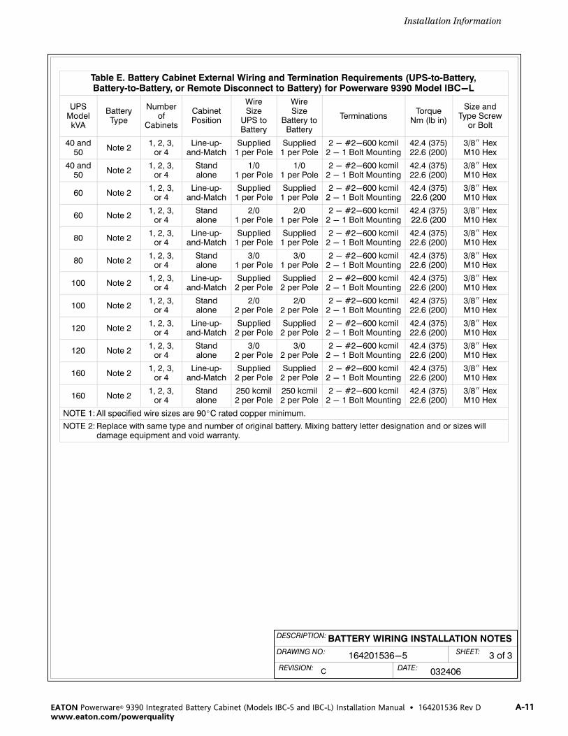
DESCRIPTION:
DATE:
DRAWING NO: 3 of 3SHEET:
REVISION: C 032406
BATTERY WIRING INSTALLATION NOTES
164201536-5
Installation Information
A-11EATON Powerware® 9390 Integrated Battery Cabinet (Models IBC-S and IBC-L) Installation Manual � 164201536 Rev Dwww.eaton.com/powerquality
Table E. Battery Cabinet External Wiring and Termination Requirements (UPS‐to‐Battery,Battery‐to‐Battery, or Remote Disconnect to Battery) for Powerware 9390 Model IBC-L
UPSModelkVA
BatteryType
Numberof
Cabinets
CabinetPosition
WireSize
UPS toBattery
WireSize
Battery toBattery
TerminationsTorque
Nm (lb in)
Size andType Screw
or Bolt
40 and50
Note 21, 2, 3,
or 4Line‐up‐
and‐MatchSupplied
1 per PoleSupplied
1 per Pole2 - #2-600 kcmil
2 - 1 Bolt Mounting42.4 (375)22.6 (200)
3/8� HexM10 Hex
40 and50
Note 21, 2, 3,
or 4Standalone
1/01 per Pole
1/01 per Pole
2 - #2-600 kcmil2 - 1 Bolt Mounting
42.4 (375)22.6 (200)
3/8� HexM10 Hex
60 Note 21, 2, 3,
or 4Line‐up‐
and‐MatchSupplied
1 per PoleSupplied
1 per Pole2 - #2-600 kcmil
2 - 1 Bolt Mounting42.4 (375)22.6 (200
3/8� HexM10 Hex
60 Note 21, 2, 3,
or 4Standalone
2/01 per Pole
2/01 per Pole
2 - #2-600 kcmil2 - 1 Bolt Mounting
42.4 (375)22.6 (200
3/8� HexM10 Hex
80 Note 21, 2, 3,
or 4Line‐up‐
and‐MatchSupplied
1 per PoleSupplied
1 per Pole2 - #2-600 kcmil
2 - 1 Bolt Mounting42.4 (375)22.6 (200)
3/8� HexM10 Hex
80 Note 21, 2, 3,
or 4Standalone
3/01 per Pole
3/01 per Pole
2 - #2-600 kcmil2 - 1 Bolt Mounting
42.4 (375)22.6 (200)
3/8� HexM10 Hex
100 Note 21, 2, 3,
or 4Line‐up‐
and‐MatchSupplied
2 per PoleSupplied
2 per Pole2 - #2-600 kcmil
2 - 1 Bolt Mounting42.4 (375)22.6 (200)
3/8� HexM10 Hex
100 Note 21, 2, 3,
or 4Standalone
2/02 per Pole
2/02 per Pole
2 - #2-600 kcmil2 - 1 Bolt Mounting
42.4 (375)22.6 (200)
3/8� HexM10 Hex
120 Note 21, 2, 3,
or 4Line‐up‐
and‐MatchSupplied
2 per PoleSupplied
2 per Pole2 - #2-600 kcmil
2 - 1 Bolt Mounting42.4 (375)22.6 (200)
3/8� HexM10 Hex
120 Note 21, 2, 3,
or 4Standalone
3/02 per Pole
3/02 per Pole
2 - #2-600 kcmil2 - 1 Bolt Mounting
42.4 (375)22.6 (200)
3/8� HexM10 Hex
160 Note 21, 2, 3,
or 4Line‐up‐
and‐MatchSupplied
2 per PoleSupplied
2 per Pole2 - #2-600 kcmil
2 - 1 Bolt Mounting42.4 (375)22.6 (200)
3/8� HexM10 Hex
160 Note 21, 2, 3,
or 4Standalone
250 kcmil2 per Pole
250 kcmil2 per Pole
2 - #2-600 kcmil2 - 1 Bolt Mounting
42.4 (375)22.6 (200)
3/8� HexM10 Hex
NOTE 1: All specified wire sizes are 90�C rated copper minimum.
NOTE 2: Replace with same type and number of original battery. Mixing battery letter designation and or sizes will damage equipment and void warranty.

Installation Information
A-12 EATON Powerware® 9390 Integrated Battery Cabinet (Models IBC-S and IBC-L) Installation Manual � 164201536 Rev D www.eaton.com/powerquality
DESCRIPTION:
DATE:
DRAWING NO: SHEET:
REVISION:B
1 of 2
091504
CONDUIT AND WIRE ENTRY LOCATIONS
TOP ENTRY CONDUIT LANDING FORDC OUTPUT, AND DC CONTROLINTERFACE CONNECTIONS.(REMOVE PANEL TO DRILL ORPUNCH CONDUIT HOLES.)
TOP VIEW
BOTTOM VIEW
STAND‐ALONE BATTERY CABINETS
BOTTOM ENTRY CONDUIT LANDINGFOR DC OUTPUT, AND DCCONTROL INTERFACECONNECTIONS.(REMOVE PANEL TO DRILL ORPUNCH CONDUIT HOLES.)
MODEL IBC-S
164201536-6

Installation Information
A-13EATON Powerware® 9390 Integrated Battery Cabinet (Models IBC-S and IBC-L) Installation Manual � 164201536 Rev Dwww.eaton.com/powerquality
DESCRIPTION:
DATE:
DRAWING NO: SHEET:
REVISION:B
2 of 2
091504
CONDUIT AND WIRE ENTRY LOCATIONS
TOP ENTRY CONDUIT LANDING FORDC OUTPUT, AND DC CONTROLINTERFACE CONNECTIONS.(REMOVE PANEL TO DRILL ORPUNCH CONDUIT HOLES.)
TOP VIEW
BOTTOM VIEW
STAND‐ALONE BATTERY CABINETS
BOTTOM ENTRY CONDUIT LANDINGFOR DC OUTPUT, AND DCCONTROL INTERFACECONNECTIONS.(REMOVE PANEL TO DRILL ORPUNCH CONDUIT HOLES.)
MODEL IBC-L
164201536-6

Installation Information
A-14 EATON Powerware® 9390 Integrated Battery Cabinet (Models IBC-S and IBC-L) Installation Manual � 164201536 Rev D www.eaton.com/powerquality
DESCRIPTION:
DATE:
DRAWING NO: SHEET:
REVISION: B
164201536-7 1 of 3
091504
BATTERY POWER AND INTERFACE
TERMINAL LOCATIONS
CABINET GROUNDING(SEPARATE INSTALLATION)
CABINET TO UPS ANDCABINET TO CABINETTERMINALS (REMOVECOVER TO ACCESSTERMINALS)
INTERFACE TERMINALBLOCK TB1 ANDCONNECTORS J3 AND P3(SEE DRAWING164201536-8 FOR DETAILS)
BATTERY BREAKER
MODEL IBC-S
GROUNDING STUDGROUNDING STUD
SEE SHEET 2 FOR DETAILS
INTER‐CABINET WIRINGACCESS TO ROUTE WIRESBETWEEN CABINETS.
INTER‐CABINET WIRINGACCESS TO ROUTE WIRESBETWEEN CABINETS.
INTER‐CABINET WIRINGACCESS TO ROUTE WIRESBETWEEN CABINETS
INTER‐CABINET WIRINGACCESS TO ROUTE WIRESBETWEEN CABINETS.
EMP

Installation Information
A-15EATON Powerware® 9390 Integrated Battery Cabinet (Models IBC-S and IBC-L) Installation Manual � 164201536 Rev Dwww.eaton.com/powerquality
DESCRIPTION:
DATE:
DRAWING NO: SHEET:
REVISION: B
2 of 3
091504
BATTERY POWER AND INTERFACE
TERMINAL LOCATIONS
CABINET TO UPS ANDCABINET TO CABINETTERMINALS (–)
CABINET TO UPS ANDCABINET TO CABINETTERMINALS (+)
MODEL IBC-S
164201536-7
TERMINAL DETAIL
NOTE: Use pressure and bus bar terminations, asnecessary, for connecting cables betweenthe UPS and battery cabinet and betweenbattery cabinets.

Installation Information
A-16 EATON Powerware® 9390 Integrated Battery Cabinet (Models IBC-S and IBC-L) Installation Manual � 164201536 Rev D www.eaton.com/powerquality
DESCRIPTION:
DATE:
DRAWING NO: SHEET:
REVISION: B
3 of 3
091504
BATTERY POWER AND INTERFACE
TERMINAL LOCATIONS
GROUNDING STUD
CABINET TO UPS ANDCABINET TO CABINETTERMINALS (-)
CABINET TO UPS ANDCABINET TO CABINETTERMINALS (+)
INTERFACE TERMINALBLOCK TB1 ANDCONNECTORS J3 AND P3(SEE DRAWING164201536-8 FOR DETAILS)
BATTERY BREAKER
MODEL IBC-L
164201536-7
GROUNDING STUD
CABINET GROUNDING(SEPARATE INSTALLATION)
NOTE: Use pressure and bus bar terminations, asnecessary, for connecting cables betweenthe UPS and battery cabinet and betweenbattery cabinets.
INTER‐CABINET WIRINGACCESS TO ROUTE WIRESBETWEEN CABINETS.
INTER‐CABINET WIRINGACCESS TO ROUTE WIRESBETWEEN CABINETS.
INTER‐CABINETWIRINGACCESS TOROUTE WIRESBETWEENCABINETS
INTER‐CABINETWIRINGACCESS TOROUTE WIRESBETWEENCABINETS.
EMP

DESCRIPTION:
DATE:
DRAWING NO: SHEET:
REVISION: C
1 of 2
032406
164201536-8
INTERFACE WIRING INSTALLATIONNOTES AND TERMINAL CONNECTIONS
BATTERYCABINET
#1
6
7
8
TB1
BATTERY AUX + 5
BATTERY AUX -
BATTERY UVR +
BATTERY UVR -
UPS
UV
BATTERYCABINET
#2
UV
BATTERYCABINET
#4
UV
BATTERYCABINET
#3
UV
TB1 TB1 TB1
6
7
8
TB1
BATTERY AUX + 5
BATTERY AUX -
BATTERY UVR +
BATTERY UVR -
UPS
BATTERYCABINET
UV
TB1
TB1
MULTIPLE BATTERY CABINETS
SINGLE BATTERY CABINET
Installation Information
A-17EATON Powerware® 9390 Integrated Battery Cabinet (Models IBC-S and IBC-L) Installation Manual � 164201536 Rev Dwww.eaton.com/powerquality
1. Use Class 1 wiring methods (as defined by the NEC) for control wiring. Install the controlwiring in separate conduit from the power wiring. The wire should be rated at 48V, 1Aminimum.
2. Battery Aux and UVR wiring should be a minimum of 18 AWG.
3. UV trip requires 48V to activate.
4. Torque screw terminals to 20 lb in.
5. Auxiliary Contacts are rated as follows:240 VAC @ 15A125 VDC @ 0.3A250 VDC @ 0.15A
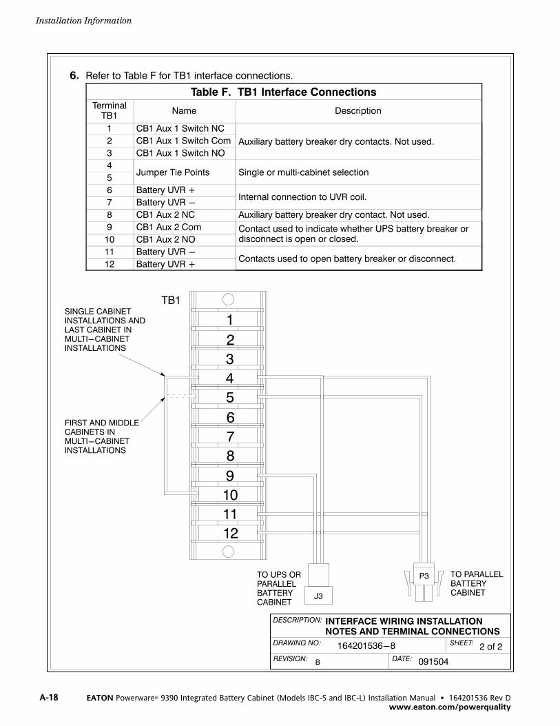
DESCRIPTION:
DATE:
DRAWING NO: SHEET:
REVISION: B
2 of 2
091504
INTERFACE WIRING INSTALLATIONNOTES AND TERMINAL CONNECTIONS
164201536-8
1
2
3
4
5
6
7
8
9
11
10
12
J3
P3TO UPS ORPARALLELBATTERYCABINET
TO PARALLELBATTERYCABINET
TB1
FIRST AND MIDDLECABINETS INMULTI-CABINETINSTALLATIONS
SINGLE CABINETINSTALLATIONS ANDLAST CABINET INMULTI-CABINETINSTALLATIONS
Installation Information
A-18 EATON Powerware® 9390 Integrated Battery Cabinet (Models IBC-S and IBC-L) Installation Manual � 164201536 Rev D www.eaton.com/powerquality
6. Refer to Table F for TB1 interface connections.
Table F. TB1 Interface ConnectionsTerminal
TB1Name Description
1 CB1 Aux 1 Switch NC
Auxiliary battery breaker dry contacts. Not used.2 CB1 Aux 1 Switch Com
3 CB1 Aux 1 Switch NO
4Jumper Tie Points Single or multi‐cabinet selection
5
6 Battery UVR +Internal connection to UVR coil.
7 Battery UVR -
8 CB1 Aux 2 NC Auxiliary battery breaker dry contact. Not used.
9 CB1 Aux 2 Com Contact used to indicate whether UPS battery breaker ordisconnect is open or closed.10 CB1 Aux 2 NO
11 Battery UVR -Contacts used to open battery breaker or disconnect.
12 Battery UVR +

Installation Information
A-19EATON Powerware® 9390 Integrated Battery Cabinet (Models IBC-S and IBC-L) Installation Manual � 164201536 Rev Dwww.eaton.com/powerquality
DESCRIPTION:
DATE:
DRAWING NO: SHEET:
REVISION: B
164201536-9 1 of 5
091504
BATTERY CABINET DIMENSIONS
FRONT VIEW
Dimensions are in millimeters [inches]
MODEL IBC-S
RIGHT SIDE VIEW
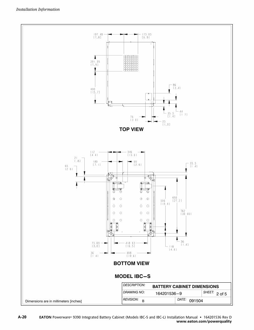
Installation Information
A-20 EATON Powerware® 9390 Integrated Battery Cabinet (Models IBC-S and IBC-L) Installation Manual � 164201536 Rev D www.eaton.com/powerquality
DESCRIPTION:
DATE:
DRAWING NO: SHEET:
REVISION: B
2 of 5
091504
BATTERY CABINET DIMENSIONS
Dimensions are in millimeters [inches]
TOP VIEW
BOTTOM VIEW
164201536-9
MODEL IBC-S

Installation Information
A-21EATON Powerware® 9390 Integrated Battery Cabinet (Models IBC-S and IBC-L) Installation Manual � 164201536 Rev Dwww.eaton.com/powerquality
DESCRIPTION:
DATE:
DRAWING NO: SHEET:
REVISION: B
3 of 5
091504
BATTERY CABINET DIMENSIONS
FRONT VIEW
Dimensions are in millimeters [inches]
MODEL IBC-L
164201536-9

Installation Information
A-22 EATON Powerware® 9390 Integrated Battery Cabinet (Models IBC-S and IBC-L) Installation Manual � 164201536 Rev D www.eaton.com/powerquality
DESCRIPTION:
DATE:
DRAWING NO: SHEET:
REVISION: B
4 of 5
091504
RIGHT SIDE VIEW
BATTERY CABINET DIMENSIONS
Dimensions are in millimeters [inches]
MODEL IBC-L
164201536-9

Installation Information
A-23EATON Powerware® 9390 Integrated Battery Cabinet (Models IBC-S and IBC-L) Installation Manual � 164201536 Rev Dwww.eaton.com/powerquality
DESCRIPTION:
DATE:
DRAWING NO: SHEET:
REVISION: B
5 of 5
091504
BATTERY CABINET DIMENSIONS
Dimensions are in millimeters [inches]
MODEL IBC-L
TOP VIEW
BOTTOM VIEW
164201536-9

Installation Information
A-24 EATON Powerware® 9390 Integrated Battery Cabinet (Models IBC-S and IBC-L) Installation Manual � 164201536 Rev D www.eaton.com/powerquality
This page intentionally left blank.

W-1EATON Powerware® 9390 Integrated Battery Cabinet (Models IBC-S and IBC-L) Installation Manual � 164201536 Rev Dwww.eaton.com/powerquality
Warranty
LIMITED FACTORY WARRANTY FOR THREE‐PHASE POWERWARE® PRODUCTS
WARRANTOR: The warrantor for the limited warranties set forth herein is Eaton Electrical Inc., a Delaware Corporation (“Eaton”).
LIMITED WARRANTY: This limited warranty (this “Warranty”) applies only to the original end-user (the “End-User”) of the Powerware
Three-Phase UPS Products (the “Product”) and cannot be transferred. This Warranty applies even in the event that the Product is initially
sold by Eaton for resale to an End-User.
LIMITED WARRANTY PERIOD: The period covered by this Warranty for Product installed [and currently located] in the fifty (50) United
States and the District of Columbia is twelve (12) months from the date of Product start-up or eighteen (18) months from the date of
Product shipment, whichever occurs first, for parts coverage and 90 days from the date of Product start-up for labor coverage. The
period covered by this Warranty for Product installed [and currently located] outside of the fifty (50) United States and the District of
Columbia is twelve (12) months from the date of Product start-up or eighteen (18) months from the date of Product shipment,
whichever occurs first, for parts coverage.
WHAT THIS LIMITED WARRANTY COVERS: The warrantor warrants that the Powerware three-phase UPS electronics, Eaton-built
accessories, and Powerware-built battery cabinets (individually and collectively, the ”Warranted Items”) are free from defects in material
and workmanship. If, in the opinion of Eaton, a Warranted Item is defective and the defect is within the terms of this Warranty, Eaton's
sole obligation will be to repair or replace such defective item (including by providing service, parts, and labor, as applicable), at the
option of Eaton. The Warranted Item will be repaired or replaced onsite at the End-User's location or such other location as determined
by Eaton. Any parts that are replaced may be new or reconditioned. All parts replaced by Eaton shall become the property of Eaton.
WHAT THIS LIMITED WARRANTY DOES NOT COVER: This Warranty does not cover any defects or damages caused by: (a) failure to
properly store the Product before installation, including the ”trickle charge” of batteries no later than the date indicated on the
packaging; (b) shipping and delivery of the Product if shipping is FOB Factory; (c) neglect, accident, abuse, misuse, misapplication,
incorrect installation; (d) repair or alteration not authorized in writing by Eaton personnel or performed by an authorized Eaton
Customer Service Engineer or Agent; or (e) improper testing, operation, maintenance, adjustment, or any modification of any kind not
authorized in writing by Eaton personnel or performed by an authorized Eaton Customer Service Engineer or Agent.
This Warranty is not valid: (a) unless an authorized Eaton Customer Service Engineer (in the USA) or Agent (outside of the USA) performs
startup and commissioning of the Product; (b) if the Product is moved to a new location by someone other than an authorized Eaton
Customer Service Engineer (in the USA) or Agent (outside of the USA); or (c) if the Product's serial numbers have been removed or are
illegible. Any Warranted Items repaired or replaced pursuant to this Warranty will be warranted for the remaining portion of the original
Warranty subject to all the terms thereof. Labor warranty is not provided for Product located outside of the fifty (50) United States or
the District of Columbia. Any equipment, parts, or materials included in the Product and not manufactured by Eaton arewarranted solely by the manufacturer of such equipment, parts, or materials and are not included as part of this Warranty.Batteries are not warranted by Eaton.
THIS WARRANTY IS THE END-USER'S SOLE REMEDY AND IS EXPRESSLY IN LIEU OF, AND THERE ARE NO OTHER EXPRESSED ORIMPLIED GUARANTEES OR WARRANTIES (INCLUDING ANY IMPLIED WARRANTY OF MERCHANTABILITY OR FITNESS FOR ANYPURPOSE, WHICH ARE EXPRESSLY DISCLAIMED).
LIMITATION OF LIABILITY: In no event shall Eaton be liable for any indirect, incidental, special, or consequential damages of any kind
or type whatsoever, or based on any claim or cause of action, however denominated. Eaton shall not be responsible for failure to provide
service or parts due to causes beyond Eaton's reasonable control. In no case will Eaton's liability under this Warranty exceed the
replacement value of the Warranted Items.
END-USER'S OBLIGATIONS: In order to receive the benefits of this Warranty, the End-User must use the Product in a normal way,
follow the Product's operation and maintenance manual, and protect against further damage to the Product if there is a covered defect.
OTHER LIMITATIONS: Eaton's obligations under this Warranty are expressly conditioned upon receipt by Eaton of all payments due to
it (including interest charges, if any). During such time as Eaton has not received payment of any amount due to it for the Product, in
accordance with the contract terms under which the Product is sold, Eaton shall have no obligation under this Warranty. Also during
such time, the period of this Warranty shall continue to run and the expiration of this Warranty shall not be extended upon payment of
any overdue or unpaid amounts.
COSTS NOT RELATED TO WARRANTY: The End-User shall be invoiced for, and shall pay for, all services not expressly provided for by
the terms of this Warranty, including without limitation site calls involving an inspection that determines no corrective maintenance is
required. Any costs for replacement equipment, installation, materials, freight charges, travel expenses, or labor of Eaton representatives
outside the terms of this Warranty will be borne by the End-User.
OBTAINING WARRANTY SERVICE: In the USA, call the Eaton Customer Reliability Center 7x24 at 800-843-9433. Outside of the USA,
call your local Eaton sales or service representative, or call the Eaton Customer Reliability Center in the USA at 919-870-3028. For
comments or questions about this Limited Factory Warranty, write to the Customer Quality Representative, 3301 Spring Forest Road,
Raleigh, North Carolina 27616 USA.

Warranty
W-2 EATON Powerware® 9390 Integrated Battery Cabinet (Models IBC-S and IBC-L) Installation Manual � 164201536 Rev D www.eaton.com/powerquality
This page intentionally left blank.


*164201536D*164201536 D