powerxl dg1 series vfd - kj electric dg1 installation...catalog number system ... total harmonic...
TRANSCRIPT
PowerXL DG1 Series VFD
Installation ManualEffective March 2014New Information

PowerXL DG1 Series VFD
PowerXL DG1 Series VFD MN040002EN—March 2014 www.eaton.com i
Disclaimer of Warranties and Limitation of Liability
The information, recommendations, descriptions, and safety notations in this document are based on Eaton’s experience and judgment and may not cover all contingencies. If further information is required, an Eaton sales office should be consulted. Sale of the product shown in this literature is subject to the terms and conditions outlined in appropriate Eaton selling policies or other contractual agreement between Eaton and the purchaser.
THERE ARE NO UNDERSTANDINGS, AGREEMENTS, WARRANTIES, EXPRESSED OR IMPLIED, INCLUDING WARRANTIES OF FITNESS FOR A PARTICULAR PURPOSE OR MERCHANTABILITY, OTHER THAN THOSE SPECIFICALLY SET OUT IN ANY EXISTING CONTRACT BETWEEN THE PARTIES. ANY SUCH CONTRACT STATES THE ENTIRE OBLIGATION OF EATON. THE CONTENTS OF THIS DOCUMENT SHALL NOT BECOME PART OF OR MODIFY ANY CONTRACT BETWEEN THE PARTIES.
In no event will Eaton be responsible to the purchaser or user in contract, in tort (including negligence), strict liability, or otherwise for any special, indirect, incidental, or consequential damage or loss whatsoever, including but not limited to damage or loss of use of equipment, plant or power system, cost of capital, loss of power, additional expenses in the use of existing power facilities, or claims against the purchaser or user by its customers resulting from the use of the information, recommendations, and descriptions contained herein. The information contained in this manual is subject to change without notice.
Cover Photo: Eaton PowerXL DG1 Series Drive

PowerXL DG1 Series VFD
ii PowerXL DG1 Series VFD MN040002EN—March 2014 www.eaton.com
Support Services
Support ServicesThe goal of Eaton is to ensure your greatest possible satisfaction with the operation of our products. We are dedicated to providing fast, friendly, and accurate assistance. That is why we offer you so many ways to get the support you need. Whether it is by phone, fax, or email, you can access Eaton’s support information 24 hours a day, seven days a week.
Our wide range of services is listed below.
You should contact your local distributor for product pricing, availability, ordering, expediting, and repairs.
Website Use the Eaton Website to find product information. You can also find information on local distributors or Eaton’s sales offices.
Website Address www.eaton.com/drives
EatonCare Customer Support Center Call the EatonCare Support Center if you need assistance with placing an order, stock availability or proof of shipment, expediting an existing order, emergency shipments, product price information, returns other than warranty returns, and information on local distributors or sales offices.
Voice: 877-ETN-CARE (386-2273) (8:00 a.m.–6:00 p.m. EST)After-Hours Emergency: 800-543-7038 (6:00 p.m.–8:00 a.m. EST)
Drives Technical Resource CenterVoice: 877-ETN-CARE (386-2273) option 2, option 6 (8:00 a.m.–5:00 p.m. Central Time U.S. [UTC –6])email: [email protected]
For Customers in Europe, ContactPhone: +49 (0) 228 6 02-3640Hotline: +49 (0) 180 5 223822email: [email protected]/moeller/aftersales

PowerXL DG1 Series VFD
PowerXL DG1 Series VFD MN040002EN—March 2014 www.eaton.com iii
Table of Contents
SAFETYBefore Commencing the Installation . . . . . . . . . . . . . . . . . . . . . . . . . . . . . . . . . viiDefinitions and Symbols . . . . . . . . . . . . . . . . . . . . . . . . . . . . . . . . . . . . . . . . . . viiiHazardous High Voltage . . . . . . . . . . . . . . . . . . . . . . . . . . . . . . . . . . . . . . . . . . . viiiWarnings and Cautions . . . . . . . . . . . . . . . . . . . . . . . . . . . . . . . . . . . . . . . . . . . viiiMotor and Equipment Safety . . . . . . . . . . . . . . . . . . . . . . . . . . . . . . . . . . . . . . . xi
CHAPTER 1—DG1 SERIES OVERVIEWHow to Use this Manual . . . . . . . . . . . . . . . . . . . . . . . . . . . . . . . . . . . . . . . . . . 1Receiving and Inspection . . . . . . . . . . . . . . . . . . . . . . . . . . . . . . . . . . . . . . . . . . 1Real Time Clock Battery Activation . . . . . . . . . . . . . . . . . . . . . . . . . . . . . . . . . . 1Rating Label . . . . . . . . . . . . . . . . . . . . . . . . . . . . . . . . . . . . . . . . . . . . . . . . . . . . 2Carton Labels (U.S. and Europe) . . . . . . . . . . . . . . . . . . . . . . . . . . . . . . . . . . . . 2Catalog Number System . . . . . . . . . . . . . . . . . . . . . . . . . . . . . . . . . . . . . . . . . . 3Power Ratings and Product Selection . . . . . . . . . . . . . . . . . . . . . . . . . . . . . . . . 4Replacement Parts . . . . . . . . . . . . . . . . . . . . . . . . . . . . . . . . . . . . . . . . . . . . . . . 6
CHAPTER 2—ENGINEERING CONSIDERATIONSIntroduction . . . . . . . . . . . . . . . . . . . . . . . . . . . . . . . . . . . . . . . . . . . . . . . . . . . . 9Electrical Power Network . . . . . . . . . . . . . . . . . . . . . . . . . . . . . . . . . . . . . . . . . . 10Input Voltage and Frequency . . . . . . . . . . . . . . . . . . . . . . . . . . . . . . . . . . . . . . . 10Input Voltage Balance . . . . . . . . . . . . . . . . . . . . . . . . . . . . . . . . . . . . . . . . . . . . 10Total Harmonic Distortion (THD) . . . . . . . . . . . . . . . . . . . . . . . . . . . . . . . . . . . . 11Reactive Power Compensation Devices . . . . . . . . . . . . . . . . . . . . . . . . . . . . . . 11
CHAPTER 3—PRODUCT OVERVIEWComponent Identification . . . . . . . . . . . . . . . . . . . . . . . . . . . . . . . . . . . . . . . . . . 12Selection Criteria . . . . . . . . . . . . . . . . . . . . . . . . . . . . . . . . . . . . . . . . . . . . . . . . 14Proper Use . . . . . . . . . . . . . . . . . . . . . . . . . . . . . . . . . . . . . . . . . . . . . . . . . . . . . 14Maintenance and Inspection . . . . . . . . . . . . . . . . . . . . . . . . . . . . . . . . . . . . . . . 15Storage . . . . . . . . . . . . . . . . . . . . . . . . . . . . . . . . . . . . . . . . . . . . . . . . . . . . . . . . 15Service and Warranty . . . . . . . . . . . . . . . . . . . . . . . . . . . . . . . . . . . . . . . . . . . . . 15
CHAPTER 4—SAFETY AND SWITCHINGFuses and Cable Cross-Sections . . . . . . . . . . . . . . . . . . . . . . . . . . . . . . . . . . . . 16Cables and Fuses . . . . . . . . . . . . . . . . . . . . . . . . . . . . . . . . . . . . . . . . . . . . . . . . 16Residual-Current Device (RCD) . . . . . . . . . . . . . . . . . . . . . . . . . . . . . . . . . . . . . 16Input Contactor . . . . . . . . . . . . . . . . . . . . . . . . . . . . . . . . . . . . . . . . . . . . . . . . . 17EMC Measures . . . . . . . . . . . . . . . . . . . . . . . . . . . . . . . . . . . . . . . . . . . . . . . . . 18
CHAPTER 5—MOTOR AND APPLICATIONMotor Selection . . . . . . . . . . . . . . . . . . . . . . . . . . . . . . . . . . . . . . . . . . . . . . . . . 19Connecting Motors in Parallel . . . . . . . . . . . . . . . . . . . . . . . . . . . . . . . . . . . . . . 19Parallel Connection of Several Motors to One Frequency Inverter . . . . . . . . . . 20Motor and Circuit Type . . . . . . . . . . . . . . . . . . . . . . . . . . . . . . . . . . . . . . . . . . . 20Bypass Operation . . . . . . . . . . . . . . . . . . . . . . . . . . . . . . . . . . . . . . . . . . . . . . . . 22Connecting EX Motors . . . . . . . . . . . . . . . . . . . . . . . . . . . . . . . . . . . . . . . . . . . . 22
PowerXL DG1 Series VFD
iv PowerXL DG1 Series VFD MN040002EN—March 2014 www.eaton.com
Table of Contents, continued
CHAPTER 6—INSTALLATION REQUIREMENTSElectrical Installation Warnings and Cautions . . . . . . . . . . . . . . . . . . . . . . . . . . 23Standard Mounting Instructions . . . . . . . . . . . . . . . . . . . . . . . . . . . . . . . . . . . . 23Dimensions . . . . . . . . . . . . . . . . . . . . . . . . . . . . . . . . . . . . . . . . . . . . . . . . . . . . 25Standard Drive Mounting . . . . . . . . . . . . . . . . . . . . . . . . . . . . . . . . . . . . . . . . . . 26Power Wiring Selection . . . . . . . . . . . . . . . . . . . . . . . . . . . . . . . . . . . . . . . . . . . 29Cable Selection: Power and Motor Leads . . . . . . . . . . . . . . . . . . . . . . . . . . . . . 29Line (Mains) and Motor Cable Installation . . . . . . . . . . . . . . . . . . . . . . . . . . . . . 29Connection Tightening Torque . . . . . . . . . . . . . . . . . . . . . . . . . . . . . . . . . . . . . 29Cable Routing . . . . . . . . . . . . . . . . . . . . . . . . . . . . . . . . . . . . . . . . . . . . . . . . . . 30Wiring the VFD . . . . . . . . . . . . . . . . . . . . . . . . . . . . . . . . . . . . . . . . . . . . . . . . . 30Rubber Grommet Installation Instructions . . . . . . . . . . . . . . . . . . . . . . . . . . . . . 32Control Board . . . . . . . . . . . . . . . . . . . . . . . . . . . . . . . . . . . . . . . . . . . . . . . . . . . 37Safe Torque Off (STO) . . . . . . . . . . . . . . . . . . . . . . . . . . . . . . . . . . . . . . . . . . . . 38Connection to Power Section . . . . . . . . . . . . . . . . . . . . . . . . . . . . . . . . . . . . . . 38Three-Phase Input Connection . . . . . . . . . . . . . . . . . . . . . . . . . . . . . . . . . . . . . 38Terminal Designations in the Power Section . . . . . . . . . . . . . . . . . . . . . . . . . . . 38Ground Connection . . . . . . . . . . . . . . . . . . . . . . . . . . . . . . . . . . . . . . . . . . . . . . 39Product Modified Sticker . . . . . . . . . . . . . . . . . . . . . . . . . . . . . . . . . . . . . . . . . . 39Checking the Cable and Motor Insulation . . . . . . . . . . . . . . . . . . . . . . . . . . . . . 39
CHAPTER 7—EMC INSTALLATIONEMC Measures in the Control Panel . . . . . . . . . . . . . . . . . . . . . . . . . . . . . . . . . 40Earthing . . . . . . . . . . . . . . . . . . . . . . . . . . . . . . . . . . . . . . . . . . . . . . . . . . . . . . . 40Screen Earth Kit . . . . . . . . . . . . . . . . . . . . . . . . . . . . . . . . . . . . . . . . . . . . . . . . . 40Installation Requirements . . . . . . . . . . . . . . . . . . . . . . . . . . . . . . . . . . . . . . . . . 41International EMC Protection Cable Requirements . . . . . . . . . . . . . . . . . . . . . . 42Installation in Corner-Grounded Network . . . . . . . . . . . . . . . . . . . . . . . . . . . . . 43Installation in IT System . . . . . . . . . . . . . . . . . . . . . . . . . . . . . . . . . . . . . . . . . . . 43
APPENDIX A—TECHNICAL DATA AND SPECIFICATIONS
APPENDIX B—INSTALLATION GUIDELINESCable and Fuse Sizing . . . . . . . . . . . . . . . . . . . . . . . . . . . . . . . . . . . . . . . . . . . . 46Temperature Deratings . . . . . . . . . . . . . . . . . . . . . . . . . . . . . . . . . . . . . . . . . . . 50Heat Loss Data . . . . . . . . . . . . . . . . . . . . . . . . . . . . . . . . . . . . . . . . . . . . . . . . . 54Brake Resistor Sizing . . . . . . . . . . . . . . . . . . . . . . . . . . . . . . . . . . . . . . . . . . . . . 54
APPENDIX C—DIMENSION DRAWINGS
APPENDIX D—SAFETY INSTRUCTIONS FOR UL AND CULUL Standards Compliance . . . . . . . . . . . . . . . . . . . . . . . . . . . . . . . . . . . . . . . . . 65Field Wiring . . . . . . . . . . . . . . . . . . . . . . . . . . . . . . . . . . . . . . . . . . . . . . . . . . . . 66

PowerXL DG1 Series VFD
PowerXL DG1 Series VFD MN040002EN—March 2014 www.eaton.com v
List of Figures
Figure 1. RTC Battery Connection . . . . . . . . . . . . . . . . . . . . . . . . . . . . . . . . . . . . . . . . . 1Figure 2. Rating Label . . . . . . . . . . . . . . . . . . . . . . . . . . . . . . . . . . . . . . . . . . . . . . . . . . 2Figure 3. Catalog Numbering System . . . . . . . . . . . . . . . . . . . . . . . . . . . . . . . . . . . . . . 3Figure 4. Drive System (PDS = Power Drive System) . . . . . . . . . . . . . . . . . . . . . . . . . . 9Figure 5. AC Power Networks with Grounded Neutral Point (TN- / TT Networks) . . . . . 10Figure 6. Description of the DG1 Series . . . . . . . . . . . . . . . . . . . . . . . . . . . . . . . . . . . . 12Figure 7. Block Diagram, Elements of DG1 Frequency Inverters . . . . . . . . . . . . . . . . . . 13Figure 8. Selection Criteria . . . . . . . . . . . . . . . . . . . . . . . . . . . . . . . . . . . . . . . . . . . . . . . 14Figure 9. Identification on the FI Circuit Breakers . . . . . . . . . . . . . . . . . . . . . . . . . . . . . 16Figure 10. EMC Measures . . . . . . . . . . . . . . . . . . . . . . . . . . . . . . . . . . . . . . . . . . . . . . . 18Figure 11. Parallel Connection . . . . . . . . . . . . . . . . . . . . . . . . . . . . . . . . . . . . . . . . . . . . . 20Figure 12. Example of a Motor Ratings Plate . . . . . . . . . . . . . . . . . . . . . . . . . . . . . . . . . 20Figure 13. Star and Delta Circuit Types . . . . . . . . . . . . . . . . . . . . . . . . . . . . . . . . . . . . . 20Figure 14. V/Hz Characteristic Curve . . . . . . . . . . . . . . . . . . . . . . . . . . . . . . . . . . . . . . . 21Figure 15. Bypass Motor Control (Example) . . . . . . . . . . . . . . . . . . . . . . . . . . . . . . . . . 22Figure 16. Mounting Space . . . . . . . . . . . . . . . . . . . . . . . . . . . . . . . . . . . . . . . . . . . . . . 24Figure 17. Type 1/12 Open Drives . . . . . . . . . . . . . . . . . . . . . . . . . . . . . . . . . . . . . . . . . . 25Figure 18. Input Power and Motor Cable Stripping Lengths . . . . . . . . . . . . . . . . . . . . . 30Figure 19. Ground Wiring . . . . . . . . . . . . . . . . . . . . . . . . . . . . . . . . . . . . . . . . . . . . . . . . 33Figure 20. Terminal Block Layout . . . . . . . . . . . . . . . . . . . . . . . . . . . . . . . . . . . . . . . . . . 35Figure 21. Basic Internal Control Wiring Diagram . . . . . . . . . . . . . . . . . . . . . . . . . . . . . . 36Figure 22. DG1 Series Adjustable Frequency Drive . . . . . . . . . . . . . . . . . . . . . . . . . . . . 37Figure 23. Thermistor STO Wiring Diagram . . . . . . . . . . . . . . . . . . . . . . . . . . . . . . . . . . 38Figure 24. Connection to Power Section . . . . . . . . . . . . . . . . . . . . . . . . . . . . . . . . . . . . 38Figure 25. Grounding . . . . . . . . . . . . . . . . . . . . . . . . . . . . . . . . . . . . . . . . . . . . . . . . . . . 39Figure 26. Product Modified Sticker . . . . . . . . . . . . . . . . . . . . . . . . . . . . . . . . . . . . . . . . 39Figure 27. EMC-Compliant Setup—460/480 Vac . . . . . . . . . . . . . . . . . . . . . . . . . . . . . . 41Figure 28. Cable Description . . . . . . . . . . . . . . . . . . . . . . . . . . . . . . . . . . . . . . . . . . . . . 42Figure 29. Locations of the EMC Screw in
Frame 1, Frame 2, Frame 3 and Frame 4 . . . . . . . . . . . . . . . . . . . . . . . . . . . . . . . . 43Figure 30. Locations of the EMC Screws in Frame 5 . . . . . . . . . . . . . . . . . . . . . . . . . . . 43Figure 31. FR1 Dimension Drawing . . . . . . . . . . . . . . . . . . . . . . . . . . . . . . . . . . . . . . . . 55Figure 32. FR1 Dimension Drawing Flange Mount . . . . . . . . . . . . . . . . . . . . . . . . . . . . 56Figure 33. FR2 Dimension Drawing . . . . . . . . . . . . . . . . . . . . . . . . . . . . . . . . . . . . . . . . 57Figure 34. FR2 Dimension Drawing Flange Mount . . . . . . . . . . . . . . . . . . . . . . . . . . . . 58Figure 35. FR3 Dimension Drawing . . . . . . . . . . . . . . . . . . . . . . . . . . . . . . . . . . . . . . . . 59Figure 36. FR3 Dimension Drawing Flange Mount . . . . . . . . . . . . . . . . . . . . . . . . . . . . 60Figure 37. FR4 Dimension Drawing . . . . . . . . . . . . . . . . . . . . . . . . . . . . . . . . . . . . . . . . 61Figure 38. FR4 Dimension Drawing Flange Mount . . . . . . . . . . . . . . . . . . . . . . . . . . . . 62Figure 39. FR5 Dimension Drawing . . . . . . . . . . . . . . . . . . . . . . . . . . . . . . . . . . . . . . . . 63Figure 40. FR5 Dimension Drawing Flange Mount . . . . . . . . . . . . . . . . . . . . . . . . . . . . 64

PowerXL DG1 Series VFD
vi PowerXL DG1 Series VFD MN040002EN—March 2014 www.eaton.com
List of Tables
Table 1. Common Abbreviations . . . . . . . . . . . . . . . . . . . . . . . . . . . . . . . . . . . . . . . . . . 1Table 2. Type 1/IP21 . . . . . . . . . . . . . . . . . . . . . . . . . . . . . . . . . . . . . . . . . . . . . . . . . . . . 4Table 3. Type 12/IP54 . . . . . . . . . . . . . . . . . . . . . . . . . . . . . . . . . . . . . . . . . . . . . . . . . . . 4Table 4. Type 1/IP21 . . . . . . . . . . . . . . . . . . . . . . . . . . . . . . . . . . . . . . . . . . . . . . . . . . . . 5Table 5. Type 12/IP54 . . . . . . . . . . . . . . . . . . . . . . . . . . . . . . . . . . . . . . . . . . . . . . . . . . . 5Table 6. Frame 1 . . . . . . . . . . . . . . . . . . . . . . . . . . . . . . . . . . . . . . . . . . . . . . . . . . . . . . 6Table 7. Frame 2 . . . . . . . . . . . . . . . . . . . . . . . . . . . . . . . . . . . . . . . . . . . . . . . . . . . . . . . 6Table 8. Frame 3 . . . . . . . . . . . . . . . . . . . . . . . . . . . . . . . . . . . . . . . . . . . . . . . . . . . . . . 7Table 9. Frame 4 . . . . . . . . . . . . . . . . . . . . . . . . . . . . . . . . . . . . . . . . . . . . . . . . . . . . . . 7Table 10. Frame 5 . . . . . . . . . . . . . . . . . . . . . . . . . . . . . . . . . . . . . . . . . . . . . . . . . . . . . . 8Table 11. Drive System Components . . . . . . . . . . . . . . . . . . . . . . . . . . . . . . . . . . . . . . . 9Table 12. Elements of DG1 Frequency Inverters . . . . . . . . . . . . . . . . . . . . . . . . . . . . . . 13Table 13. Maintenance Measures and Intervals . . . . . . . . . . . . . . . . . . . . . . . . . . . . . . 15Table 14. Maximum Motor Cable Length by Frame Size
without dV/dT Protected C2 Ratings . . . . . . . . . . . . . . . . . . . . . . . . . . . . . . . . . . . 18Table 15. Assignment of Frequency Inverters to Example Motor Circuit . . . . . . . . . . . . 21Table 16. Bypass Motor Control . . . . . . . . . . . . . . . . . . . . . . . . . . . . . . . . . . . . . . . . . . . 22Table 17. Space Requirements for Mounting the DG1 Series VFD and Airflow . . . . . . . 24Table 18. Mounting Drive Dimensions . . . . . . . . . . . . . . . . . . . . . . . . . . . . . . . . . . . . . . 25Table 19. Tightening Torque . . . . . . . . . . . . . . . . . . . . . . . . . . . . . . . . . . . . . . . . . . . . . . 29Table 20. Spacing Between Parallel Motor Cables . . . . . . . . . . . . . . . . . . . . . . . . . . . . 29Table 21. Maximum Motor Cable Length by Frame Size
without dV/dT Protected C2 Ratings . . . . . . . . . . . . . . . . . . . . . . . . . . . . . . . . . . . 29Table 22. Input Power and Motor Cable Stripping and Wire Lengths . . . . . . . . . . . . . . 30Table 23. I/O Connection . . . . . . . . . . . . . . . . . . . . . . . . . . . . . . . . . . . . . . . . . . . . . . . . 34Table 24. I/O Specifications . . . . . . . . . . . . . . . . . . . . . . . . . . . . . . . . . . . . . . . . . . . . . . 35Table 25. 1st Environment 2nd Environment EMC Levels
According to EN 61800-3 (2004) . . . . . . . . . . . . . . . . . . . . . . . . . . . . . . . . . . . . . . . 42Table 26. Control Wiring Requirements . . . . . . . . . . . . . . . . . . . . . . . . . . . . . . . . . . . . . 42Table 27. Cable Categories . . . . . . . . . . . . . . . . . . . . . . . . . . . . . . . . . . . . . . . . . . . . . . . 42Table 28. PowerXL Series—DG1 . . . . . . . . . . . . . . . . . . . . . . . . . . . . . . . . . . . . . . . . . . 44Table 29. North America Cable and Fuse Sizes—208 Vac to 240 Vac Ratings . . . . . . . . 46Table 30. International Cable and Fuse Sizes—208 Vac to 240 Vac Ratings . . . . . . . . . 47Table 31. North America Cable and Fuse Sizes—440 Vac to 500 Vac Ratings . . . . . . . . 48Table 32. International Cable and Fuse Sizes—380 Vac to 440 Vac Ratings . . . . . . . . . 49Table 33. 230V Temperature and Switching Frequency Deratings (VT) . . . . . . . . . . . . . 50Table 34. 230V Temperature and Switching Frequency Deratings (CT) . . . . . . . . . . . . . 51Table 35. 460V Temperature and Switching Frequency Deratings (VT) . . . . . . . . . . . . . 52Table 36. 460V Temperature and Switching Frequency Deratings (CT) . . . . . . . . . . . . . 53Table 37. Heat Loss Data . . . . . . . . . . . . . . . . . . . . . . . . . . . . . . . . . . . . . . . . . . . . . . . . 54Table 38. Brake Resistor Sizing Data . . . . . . . . . . . . . . . . . . . . . . . . . . . . . . . . . . . . . . . 54Table 39. Fuse Ratings—400V Drive Series . . . . . . . . . . . . . . . . . . . . . . . . . . . . . . . . . . 65Table 40. Fuse Ratings—230V Drive Series . . . . . . . . . . . . . . . . . . . . . . . . . . . . . . . . . . 66Table 41. Required Line and Motor Wire Torque (400V) . . . . . . . . . . . . . . . . . . . . . . . . . 66Table 42. Required Line and Motor Wire Torque (230V) . . . . . . . . . . . . . . . . . . . . . . . . 67Table 43. Required Line and Motor Wire Torque (400V) . . . . . . . . . . . . . . . . . . . . . . . . 67Table 44. Required Line and Motor Wire Torque (230V) . . . . . . . . . . . . . . . . . . . . . . . . 68

PowerXL DG1 Series VFD
PowerXL DG1 Series VFD MN040002EN—March 2014 www.eaton.com vii
Safety
Warning!Dangerous Electrical Voltage!
Before Commencing the Installation● Disconnect the power supply of the device
● Ensure that devices cannot be accidentally restarted
● Verify isolation from the supply
● Earth and short circuit the device
● Cover or enclose any adjacent live components
● Only suitably qualified personnel in accordance with EN 50110-1/-2 (VDE 0105 Part 100) may work on this device/system
● Before installation and before touching the device ensure that you are free of electrostatic charge
● The functional earth (FE, PES) must be connected to the protective earth (PE) or the potential equalization. The system installer is responsible for implementing this connection
● Connecting cables and signal lines should be installed so that inductive or capacitive interference does not impair the automation functions
● Install automation devices and related operating elements in such a way that they are well protected against unintentional operation
● Suitable safety hardware and software measures should be implemented for the I/O interface so that an open circuit on the signal side does not result in undefined states in the automation devices
● Ensure a reliable electrical isolation of the extra-low voltage of the 24V supply. Only use power supply units complying with IEC 60364-4-41 (VDE 0100 Part 410) or HD384.4.41 S2
● Deviations of the input voltage from the rated value must not exceed the tolerance limits given in the specifications, otherwise this may cause malfunction and dangerous operation
● Emergency stop devices complying with IEC/EN 60204-1 must be effective in all operating modes of the automation devices. Unlatching the emergency-stop devices must not cause a restart
● Devices that are designed for mounting in housings or control cabinets must only be operated and controlled after they have been installed and with the housing closed. Desktop or portable units must only be operated and controlled in enclosed housings
● Measures should be taken to ensure the proper restart of programs interrupted after a voltage dip or failure. This should not cause dangerous operating states even for a short time. If necessary, emergency-stop devices should be implemented
● Wherever faults in the automation system may cause injury or material damage, external measures must be implemented to ensure a safe operating state in the event of a fault or malfunction (for example, by means of separate limit switches, mechanical interlocks, and so on)
● Depending on their degree of protection, adjustable frequency drives may contain live bright metal parts, moving or rotating components, or hot surfaces during and immediately after operation
● Removal of the required covers, improper installation, or incorrect operation of motor or adjustable frequency drive may cause the failure of the device and may lead to serious injury or damage
● The applicable national accident prevention and safety regulations apply to all work carried out on live adjustable frequency drives
● The electrical installation must be carried out in accordance with the relevant regulations (for example, with regard to cable cross sections, fuses, PE)
● Transport, installation, commissioning, and maintenance work must be carried out only by qualified personnel (IEC 60364, HD 384 and national occupational safety regulations)
● Installations containing adjustable frequency drives must be provided with additional monitoring and protective devices in accordance with the applicable safety regulations. Modifications to the adjustable frequency drives using the operating software are permitted
● All covers and doors must be kept closed during operation
● To reduce hazards for people or equipment, the user must include in the machine design measures that restrict the consequences of a malfunction or failure of the drive (increased motor speed or sudden standstill of motor). These measures include:
● Other independent devices for monitoring safety-related variables (speed, travel, end positions, and so on)
● Electrical or non-electrical system-wide measures (electrical or mechanical interlocks)
● Never touch live parts or cable connections of the adjustable frequency drive after it has been disconnected from the power supply. Due to the charge in the capacitors, these parts may still be live after disconnection. Fit appropriate warning signs

PowerXL DG1 Series VFD
viii PowerXL DG1 Series VFD MN040002EN—March 2014 www.eaton.com
Read this manual thoroughly and make sure you understand the procedures before you attempt to install, set up, operate or carry out any maintenance work on this DG1 Adjustable Frequency Drive.
Definitions and Symbols
WARNINGThis symbol indicates high voltage. It calls your attentionto items or operations that could be dangerous to youand other persons operating this equipment. Read themessage and follow the instructions carefully.
This symbol is the “Safety Alert Symbol.” It occurs witheither of two signal words: CAUTION or WARNING, asdescribed below.
WARNINGIndicates a potentially hazardous situation which, if notavoided, can result in serious injury or death.
CAUTIONIndicates a potentially hazardous situation which, if notavoided, can result in minor to moderate injury, or seriousdamage to the product. The situation described in theCAUTION may, if not avoided, lead to serious results.Important safety measures are described in CAUTION (aswell as WARNING).
Hazardous High Voltage
WARNINGMotor control equipment and electronic controllers areconnected to hazardous line voltages. When servicingdrives and electronic controllers, there may be exposedcomponents with housings or protrusions at or aboveline potential. Extreme care should be taken to protectagainst shock.
● Stand on an insulating pad and make it a habit to useonly one hand when checking components.
● Always work with another person in case anemergency occurs.
● Disconnect power before checking controllers orperforming maintenance.
● Be sure equipment is properly earthed.
● Wear safety glasses whenever working on electroniccontrollers or rotating machinery.
WARNINGThe components in the drive’s power section remainenergized after the supply voltage has been switched off.After disconnecting the supply, wait at least five minutesbefore removing the cover to allow the intermediatecircuit capacitors to discharge.
Pay attention to hazard warnings!
DANGER5 MIN
WARNINGElectric shock hazard—risk of injuries! Carry out wiringwork only if the unit is de-energized.
WARNINGDo not perform any modifications on the AC drive whenit is connected to mains.
Warnings and Cautions
WARNINGBe sure to ground the unit following the instructions inthis manual. Ungrounded units may cause electric shockand/or fire.
WARNINGThis equipment should only be installed, adjusted, andserviced by qualified electrical maintenance personnelfamiliar with the construction and operation of this typeof equipment and the hazards involved. Failure toobserve this precaution could result in death or severeinjury.
WARNINGComponents within the drive are live when it isconnected to power. Contact with this voltage isextremely dangerous and may cause death or severeinjury.
WARNINGLine terminals (L1, L2, L3), motor terminals (U, V, W) andthe DC link/brake resistor terminals (DC–, DC+/R+, R–)are live when the drive is connected to power, even if themotor is not running. Contact with this voltage isextremely dangerous and may cause death or severeinjury.

PowerXL DG1 Series VFD
PowerXL DG1 Series VFD MN040002EN—March 2014 www.eaton.com ix
WARNINGEven though the control I/O-terminals are isolated fromline voltage, the relay outputs and other I/O-terminalsmay have dangerous voltage present even when thedrive is disconnected from power. Contact with thisvoltage is extremely dangerous and may cause death orsevere injury.
WARNINGThis equipment has a large capacitive leakage currentduring operation, which can cause enclosure parts to beabove ground potential. Proper grounding, as describedin this manual, is required. Failure to observe thisprecaution could result in death or severe injury.
WARNINGBefore applying power to this drive, make sure that thefront and cable covers are closed and fastened to preventexposure to potential electrical fault conditions. Failureto observe this precaution could result in death or severeinjury.
WARNINGAn upstream disconnect/protective device must beprovided as required by the National Electric Code®
(NEC®). Failure to follow this precaution may result indeath or severe injury.
WARNINGThis drive can cause a DC current in the protectiveearthing conductor. Where a residual current-operatedprotective (RCD) or monitoring (RCM) device is used forprotection in case of direct or indirect contact, only anRCD or RCM of Type B is allowed on the supply side ofthis product.
WARNINGCarry out wiring work only after the drive has beencorrectly mounted and secured.
WARNINGBefore opening the drive covers:
● Disconnect all power to the drive, including externalcontrol power that may be present.
● Wait a minimum of five minutes after all the lights onthe keypad are off. This allows time for the DC buscapacitors to discharge.
● A hazard voltage may still remain in the DC buscapacitors even if the power has been turned off.Confirm that the capacitors have fully discharged bymeasuring their voltage using a multimeter set tomeasure the DC voltage.
Failure to follow these precautions may cause death orsevere injury.
WARNINGThe opening of the branch-circuit protective device maybe an indication that a fault current has been interrupted.To reduce the risk of fire or electric shock, current-carryingparts and other components of the controller shouldbe examined and replaced if damaged. If burnout of thecurrent element of an overload relay occurs, the completeoverload relay must be replaced.
WARNINGOperation of this equipment requires detailedinstallation and operation instructions provided in theInstallation/Operation manual intended for use with thisproduct. This information is provided on the CD-ROM,floppy diskette(s) or other storage device included in thecontainer this device was packaged in. it should beretained with this device at all times. A hard copy of thisinformation may be ordered from Eaton literaturefulfillment.

PowerXL DG1 Series VFD
x PowerXL DG1 Series VFD MN040002EN—March 2014 www.eaton.com
WARNINGBefore servicing the drive:
● Disconnect all power to the drive, including externalcontrol power that may be present.
● Place a “DO NOT TURN ON” label on the disconnectdevice.
● Lock the disconnect device in the open position.
Failure to follow these instructions will result in death orserious injury.
WARNINGThe drive outputs (U, V, W) must not be connected to theinput voltage or the utility line power as severe damageto the device may occur and there may be a risk of fire.
WARNINGThe heat sink and/or outer enclosure may reach a hightemperature.
Pay attention to hazard warnings!
Hot Surface—Risk of Burn. DO NOT TOUCH!
CAUTIONAny electrical or mechanical modification to this drive withoutprior written consent of Eaton will void all warranties and mayresult in a safety hazard in addition and voiding of the UL®
listing.
CAUTIONInstall this drive on flame-resistant material such as a steelplate to reduce the risk of fire.
CAUTIONInstall this drive on a perpendicular surface that is able tosupport the weight of the drive and is not subject tovibration, to lessen the risk of the drive falling and beingdamaged and/or causing personal injury.
CAUTIONPrevent foreign material such as wire clippings or metalshavings from entering the drive enclosure, as this maycause arcing damage and fire.
CAUTIONInstall this drive in a well-ventilated room that is not subjectto temperature extremes, high humidity, or condensation,and avoid locations that are directly exposed to sunlight, orhave high concentrations of dust, corrosive gas, explosivegas, inflammable gas, grinding fluid mist, etc. Improperinstallation may result in a fire hazard.
CAUTIONWhen selecting the cable cross-section, take the voltagedrop under load conditions into account. The consideration ofother standards is the responsibility of the user.
The user is responsible for compliance with all international and national electrical standards in force concerning protective grounding of all equipment.
CAUTIONThe specified minimum PE conductor cross-sections in thismanual must be maintained.
Touch current in this equipment exceeds 3.5 mA (AC). The minimum size of the protective earthing conductor shall comply with the requirements of EN 61800-5-1 and/or the local safety regulations.
CAUTIONTouch currents in this frequency inverter are greater than3.5 mA (AC). According to product standard IEC/EN61800-5-1, an additional equipment grounding conductor ofthe same cross-sectional area as the original protectiveearthing conductor must be connected, or the cross-sectionof the equipment grounding conductor must be at least10 mm2 Cu. Drive requires that only copper conductor shouldbe used.
CAUTIONDebounced inputs may not be used in the safety circuitdiagram. Residual current circuit breakers (RCD) are only tobe installed between the AC power supply network and thedrive.
CAUTIONDebounced inputs may not be used in the safety circuitdiagram. If you are connecting multiple motors on one drive,you must design the contactors for the individual motorsaccording to utilization category AC-3.
Selecting the motor contactor is done according to the rated operational current of the motor to be connected.

PowerXL DG1 Series VFD
PowerXL DG1 Series VFD MN040002EN—March 2014 www.eaton.com xi
CAUTIONDebounced inputs may not be used in the safety circuitdiagram. A changeover between the drive and the inputsupply must take place in a voltage-free state.
CAUTIONDebounced inputs may not be used in the safety circuitdiagram. Fire hazard!
Only use cables, protective switches, and contactors that feature the indicated permissible nominal current value.
CAUTIONBefore connecting the drive to AC mains make sure that theEMC protection class settings of the drive are appropriatelymade according to instructions in this manual.
● If the drive is to be used in a floating distribution network,remove screws at MOV and EMC. See “Installation inCorner-Grounded Network” on Page 43 and “Installation inIT System” on Page 43 respectively.
● Disconnect the internal EMC filter when installing the driveon an IT system (an ungrounded power system or ahigh-resistance-grounded [over 30 ohm] power system),otherwise the system will be connected to groundpotential through the EMC filter capacitors. This maycause danger, or damage the drive.
● Disconnect the internal EMC filter when installing the driveon a corner grounded TN system, otherwise the drive willbe damaged.
Note: When the internal EMC filter is disconnected, the drive might be not EMC compatible.
● Do not attempt to install or remove the MOV or EMCscrews while power is applied to the drive’s inputterminals.
Motor and Equipment Safety
CAUTIONDo not perform any meggar or voltage withstand tests onany part of the drive or its components. Improper testing mayresult in damage.
CAUTIONPrior to any tests or measurements of the motor or themotor cable, disconnect the motor cable at the drive outputterminals (U, V, W) to avoid damaging the drive during motoror cable testing.
CAUTIONDo not touch any components on the circuit boards. Staticvoltage discharge may damage the components.
CAUTIONBefore starting the motor, check that the motor is mountedproperly and aligned with the driven equipment. Ensure thatstarting the motor will not cause personal injury or damageequipment connected to the motor.
CAUTIONSet the maximum motor speed (frequency) in the driveaccording to the requirements of the motor and theequipment connected to it. Incorrect maximum frequencysettings can cause motor or equipment damage and personalinjury.
CAUTIONBefore reversing the motor rotation direction, ensure thatthis will not cause personal injury or equipment damage.
CAUTIONMake sure that no power correction capacitors areconnected to the drive output or the motor terminals toprevent drive malfunction and potential damage.
CAUTIONMake sure that the drive output terminals (U, V, W) are notconnected to the utility line power as severe damage to thedrive may occur.
CAUTIONWhen the control terminals of two or more drive units areconnected in parallel, the auxiliary voltage for these controlconnections must be taken from a single source which caneither be one of the units or an external supply.
CAUTIONThe drive will start up automatically after an input voltageinterruption if the external run command is on.
CAUTIONDo not control the motor with the disconnecting device(disconnecting means); instead, use the control panel startand stop keys and, or commands via the I/O board of thedrive. The maximum allowed number of charging cycles ofthe DC capacitors (i.e. power-ups by applying power) is five inten minutes.

PowerXL DG1 Series VFD
xii PowerXL DG1 Series VFD MN040002EN—March 2014 www.eaton.com
CAUTIONImproper drive operation:
● If the drive is not turned on for a long period, theperformance of its electrolytic capacitors will be reduced.
● If it is stopped for a prolonged period, turn the drive on atleast every six months for at least 5 hours to restore theperformance of the capacitors, and then check itsoperation. It is recommended that the drive is notconnected directly to the line voltage. The voltage shouldbe increased gradually using an adjustable AC source.
Failure to follow these instructions can result in injuryand/or equipment damage.
For more technical information, contact the factory or your local Eaton sales representative.
Chapter 1—DG1 Series Overview
DG1 Series VFD MN040002EN—March 2014 www.eaton.com 1
Chapter 1—DG1 Series Overview
This chapter describes the purpose and contents of this manual, the receiving inspection recommendations and the DG1 Series Open Drive catalog numbering system.
How to Use this Manual
The purpose of this manual is to provide you with information necessary to install, set and customize parameters, start up, troubleshoot and maintain the Eaton DG1 Series adjustable frequency drive (AFD). To provide for safe installation and operation of the equipment, read the safety guidelines at the beginning of this manual and follow the procedures outlined in the following chapters before connecting power to the DG1 Series AFD. Keep this operating manual handy and distribute to all users, technicians and maintenance personnel for reference.
Receiving and Inspection
The DG1 Series AFD has met a stringent series of factory quality requirements before shipment. It is possible that packaging or equipment damage may have occurred during shipment. After receiving your DG1 Series AFD, please check for the following:
Check to make sure that the package includes the Instruction Leaflet (IL040016EN), Quick Start Guide (MN040006EN), User Manual CD (CD040002EN) and accessory packet. The accessory packet includes:
● Rubber grommets
● Control cable grounding clamps
● Additional grounding screw
Inspect the unit to ensure it was not damaged during shipment.
Make sure that the part number indicated on the nameplate corresponds with the catalog number on your order.
If shipping damage has occurred, please contact and file a claim with the carrier involved immediately.
If the delivery does not correspond to your order, please contact your Eaton Electrical representative.
Note: Do not destroy the packing. The template printed on the protective cardboard can be used for marking the mounting points of the DG1 AFD on the wall or in a cabinet.
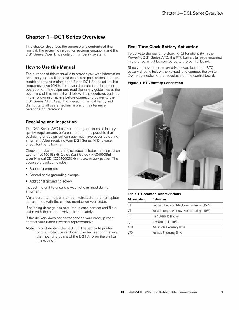
Real Time Clock Battery Activation
To activate the real time clock (RTC) functionality in the PowerXL DG1 Series AFD, the RTC battery (already mounted in the drive) must be connected to the control board.
Simply remove the primary drive cover, locate the RTC battery directly below the keypad, and connect the white 2-wire connector to the receptacle on the control board.
Figure 1. RTC Battery Connection
Table 1. Common Abbreviations
Abbreviation Definition
CT Constant torque with high overload rating (150%)
VT Variable torque with low overload rating (110%)
IH High Overload (150%)
IL Low Overload (110%)
AFD Adjustable Frequency Drive
VFD Variable Frequency Drive

Chapter 1—DG1 Series Overview
2 DG1 Series VFD MN040002EN—March 2014 www.eaton.com
Rating Label
Figure 2. Rating Label
Carton Labels (U.S. and Europe)
Same as rating label shown above.
ContainsSN, PN,Type, Date
ContainsEAN Code
Date Code: 20131118
ContainsNAED Code

Chapter 1—DG1 Series Overview
DG1 Series VFD MN040002EN—March 2014 www.eaton.com 3
Catalog Number System
Figure 3. Catalog Numbering System
Internal Brake Chopper
N = No brake chopperB = Brake chopper
Series Power Part Options
D G1 – 3 4 4D8 F B – C 21 C
Input/Output Voltage Rating
2 = 230V (208–240V, –15%, +10%)4 = 400V (380–500V, –15%, +10%)5 = 575V (525–600V, –15%, +10%)
Basic Naming
D = Drive
Output Current Rating (CT)
208–240V 380–500V 525–600V
3D7 = 3.7A, 0.55 kW, 0.75 hp4D8 = 4.8A, 0.75 kW, 1 hp6D6 = 6.6A, 1.1 kW, 1.5 hp7D8 = 7.8A, 1.5 kW, 2 hp011 = 11A, 2.2 kW, 3 hp012 = 12.5A, 3 kW, 5 hp (VT)017 = 17.5A, 3.7 kW, 5 hp025 = 25A, 5.5 kW, 7.5 hp031 = 31A, 7.5 kW, 10 hp048 = 48A, 11 kW, 15 hp061 = 61A, 15 kW, 20 hp075 = 75A, 18.5 kW, 25 hp088 = 88A, 22 kW, 30 hp114 = 114A, 30 kW, 40 hp143 = 143A, 37 kW, 50 hp170 = 170A, 45 kW, 60 hp211 = 211A, 55 kW, 75 hp261 = 261A, 75 kW, 100 hp
2D2 = 2.2A, 0.75 kW, 1 hp3D3 = 3.3A, 1.1 kW, 1.5 hp4D3 = 4.3A, 1.5 kW, 2 hp5D6 = 5.6A, 2.2 kW, 3 hp7D6 = 7.6A, 3 kW, 5 hp9D0 = 9A, 4 kW, 7.5 hp (VT)012 = 12A, 5.5 kW, 7.5 hp016 = 16A, 7.5 kW, 10 hp023 = 23A, 11 kW, 15 hp031 = 31A, 15 kW, 20 hp038 = 38A, 18 kW, 25 hp046 = 46A, 22 kW, 30 hp061 = 61A, 30 kW, 40 hp072 = 72A, 37 kW, 50 hp087 = 87A, 45 kW, 60 hp105 = 105A, 55 kW, 75 hp140 = 140A, 75 kW, 100 hp170 = 170A, 90 kW, 125 hp205 = 205A, 110 kW, 150 hp261 = 261A, 132 kW, 200 hp
3D3 = 3.3A, 1.5 kW, 2 hp4D5 = 4.5A, 2.2 kW, 3 hp7D5 = 7.5A, 3.7 kW, 5 hp010 = 10A, 5.5 kW, 7.5 hp013 = 13.5A, 7.5 kW, 10 hp018 = 18A, 11 kW, 15 hp022 = 22A, 15 kW, 20 hp027 = 27A, 18 kW, 25 hp034 = 34A, 22 kW, 30 hp041 = 41A, 30 kW, 40 hp052 = 52A, 37 kW, 50 hp062 = 62A, 45 kW, 60 hp080 = 80A, 55 kW, 75 hp100 = 100A, 75 kW, 100 hp125 = 125A, 90 kW, 125 hp144 = 144A, 110 kW, 150 hp208 = 208A, 160 kW, 200 hp
Series
G1 = General purpose
Phase Reference
3 = 3~ INPUT/3~ OUTPUT
Internal EMC Filter
F = Internal EMC filter
Coating of Boards
C = Coated
Enclosure (IP Rating)
21 = IP21/Type 154 = IP54/Type 12
Display Option
C = LCD (graphical)

Chapter 1—DG1 Series Overview
4 DG1 Series VFD MN040002EN—March 2014 www.eaton.com
Power Ratings and Product Selection
DG1 Series Drives—208–240 Volt
Table 2. Type 1/IP21
Table 3. Type 12/IP54
Note1 FR6 available in 2015.
Frame Size230V, 50 HzkW Rating (CT/IH)
230V, 50 HzkW Rating (VT/IL)
230V, 60 Hz hp (CT/IH)
230V, 60 Hzhp (VT/IL)
CurrentA (CT/IH)
CurrentA (VT/IL) Catalog Number
FR1 0.55 0.75 0.75 1 3.7 4.8 DG1-323D7FB-C21C
0.75 1.1 1 1.5 4.8 6.6 DG1-324D8FB-C21C
1.1 1.5 1.5 2 6.6 7.8 DG1-326D6FB-C21C
1.5 2.2 2 3 7.8 11 DG1-327D8FB-C21C
2.2 3 3 — 11 12.5 DG1-32011FB-C21C
FR2 3 3.7 — 5 12.5 17.5 DG1-32012FB-C21C
3.7 5.5 5 7.5 17.5 25 DG1-32017FB-C21C
5.5 7.5 7.5 10 25 31 DG1-32025FB-C21C
FR3 7.5 11 10 15 31 48 DG1-32031FB-C21C
11 15 15 20 48 61 DG1-32048FB-C21C
FR4 15 18.5 20 25 61 75 DG1-32061FN-C21C
18.5 22 25 30 75 88 DG1-32075FN-C21C
22 30 30 40 88 114 DG1-32088FN-C21C
FR5 30 37 40 50 114 143 DG1-32114FN-C21C
37 45 50 60 143 170 DG1-32143FN-C21C
45 55 60 75 170 211 DG1-32170FN-C21C
FR6 1 55 75 75 100 211 261 DG1-32211FN-C21C
75 90 100 125 261 312 DG1-32261FN-C21C
Frame Size230V, 50 HzkW Rating (CT/IH)
230V, 50 HzkW Rating (VT/IL)
230V, 60 Hz hp (CT/IH)
230V, 60 Hzhp (VT/IL)
CurrentA (CT/IH)
CurrentA (VT/IL) Catalog Number
FR1 0.55 0.75 0.75 1 3.7 4.8 DG1-323D7FB-C54C
0.75 1.1 1 1.5 4.8 6.6 DG1-324D8FB-C54C
1.1 1.5 1.5 2 6.6 7.8 DG1-326D6FB-C54C
1.5 2.2 2 3 7.8 11 DG1-327D8FB-C54C
2.2 3 3 — 11 12.5 DG1-32011FB-C54C
FR2 3 3.7 — 5 12.5 17.5 DG1-32012FB-C54C
3.7 5.5 5 7.5 17.5 25 DG1-32017FB-C54C
5.5 7.5 7.5 10 25 31 DG1-32025FB-C54C
FR3 7.5 11 10 15 31 48 DG1-32031FB-C54C
11 15 15 20 48 61 DG1-32048FB-C54C
FR4 15 18.5 20 25 61 75 DG1-32061FN-C54C
18.5 22 25 30 75 88 DG1-32075FN-C54C
22 30 30 40 88 114 DG1-32088FN-C54C
FR5 30 37 40 50 114 143 DG1-32114FN-C54C
37 45 50 60 143 170 DG1-32143FN-C54C
45 55 60 75 170 211 DG1-32170FN-C54C
FR6 1 55 75 75 100 211 261 DG1-32211FN-C54C
75 90 100 125 261 312 DG1-32261FN-C54C

Chapter 1—DG1 Series Overview
DG1 Series VFD MN040002EN—March 2014 www.eaton.com 5
DG1 Series Drives—380–500 Volt
Table 4. Type 1/IP21
Table 5. Type 12/IP54
Note1 FR6 available in 2015.
Frame Size400V, 50 HzkW Rating (CT/IH)
400V, 50 HzkW Rating (VT/IL)
460V, 60 Hz hp (CT/IH)
460V, 60 Hzhp (VT/IL)
CurrentA (CT/IH)
CurrentA (VT/IL) Catalog Number
FR1 0.75 1.1 1 1.5 2.2 3.3 DG1-342D2FB-C21C
1.1 1.5 1.5 2 3.3 4.3 DG1-343D3FB-C21C
1.5 2.2 2 3 4.3 5.6 DG1-344D3FB-C21C
2.2 3 3 5 5.6 7.6 DG1-345D6FB-C21C
3 4 5 — 7.6 9 DG1-347D6FB-C21C
4 5.5 — 7.5 9 12 DG1-349D0FB-C21C
FR2 5.5 7.5 7.5 10 12 16 DG1-34012FB-C21C
7.5 11 10 15 16 23 DG1-34016FB-C21C
11 15 15 20 23 31 DG1-34023FB-C21C
FR3 15 18.5 20 25 31 38 DG1-34031FB-C21C
18.5 22 25 30 38 46 DG1-34038FB-C21C
22 30 30 40 46 61 DG1-34046FB-C21C
FR4 30 37 40 50 61 72 DG1-34061FN-C21C
37 45 50 60 72 87 DG1-34072FN-C21C
45 55 60 75 87 105 DG1-34087FN-C21C
FR5 55 75 75 100 105 140 DG1-34105FN-C21C
75 90 100 125 140 170 DG1-34140FN-C21C
90 110 125 150 170 205 DG1-34170FN-C21C
FR6 1 110 132 150 200 205 261 DG1-34205FN-C21C
132 160 200 250 261 310 DG1-34261FN-C21C
Frame Size400V, 50 HzkW Rating (CT/IH)
400V, 50 HzkW Rating (VT/IL)
460V, 60 Hz hp (CT/IH)
460V, 60 Hzhp (VT/IL)
CurrentA (CT/IH)
CurrentA (VT/IL) Catalog Number
FR1 0.75 1.1 1 1.5 2.2 3.3 DG1-342D2FB-C54C
1.1 1.5 1.5 2 3.3 4.3 DG1-343D3FB-C54C
1.5 2.2 2 3 4.3 5.6 DG1-344D3FB-C54C
2.2 3 3 5 5.6 7.6 DG1-345D6FB-C54C
3 4 5 — 7.6 9 DG1-347D6FB-C54C
4 5.5 — 7.5 9 12 DG1-349D0FB-C54C
FR2 5.5 7.5 7.5 10 12 16 DG1-34012FB-C54C
7.5 11 10 15 16 23 DG1-34016FB-C54C
11 15 15 20 23 31 DG1-34023FB-C54C
FR3 15 18.5 20 25 31 38 DG1-34031FB-C54C
18.5 22 25 30 38 46 DG1-34038FB-C54C
22 30 30 40 46 61 DG1-34046FB-C54C
FR4 30 37 40 50 61 72 DG1-34061FN-C54C
37 45 50 60 72 87 DG1-34072FN-C54C
45 55 60 75 87 105 DG1-34087FN-C54C
FR5 55 75 75 100 105 140 DG1-34105FN-C54C
75 90 100 125 140 170 DG1-34140FN-C54C
90 110 125 150 170 205 DG1-34170FN-C54C
FR6 1 110 132 150 200 205 261 DG1-34205FN-C54C
132 160 200 250 261 310 DG1-34261FN-C54C

Chapter 1—DG1 Series Overview
6 DG1 Series VFD MN040002EN—March 2014 www.eaton.com
Replacement Parts
Table 6. Frame 1
Notes1 Factory recommended spare parts.2 575V available in 2015.
Table 7. Frame 2
Notes1 Factory recommended spare parts.2 575V available in 2015.
Catalog Number Catalog Number Catalog Number
Description 230V 480V 575V
Standard keypad 1 DXG-KEY-LCD DXG-KEY-LCD DXG-KEY-LCD
Main control board 1 DXG-SPR-CTRLBOARD DXG-SPR-CTRLBOARD DXG-SPR-CTRLBOARD
Control board cover DXG-SPR-BCOVER DXG-SPR-BCOVER DXG-SPR-BCOVER
Type 1/IP21 standard cover DXG-SPR-FR1CVR DXG-SPR-FR1CVR 2
Main fan kit 1 DXG-SPR-FR1FAN DXG-SPR-FR1FAN 2
Control fan DXG-SPR-2FR1CF DXG-SPR-4FR1CF 2
Main power board DXG-SPR-2FR1MPB DXG-SPR-4FR1MPB 2
EMI board DXG-SPR-2FR1EB DXG-SPR-4FR1EB 2
Middle chassis cover DXG-SPR-FR1MCC DXG-SPR-FR1MCC 2
Outer housing DXG-SPR-FR1OH DXG-SPR-FR1OH 2
UL conduit plate DXG-SPR-FR1CPUL DXG-SPR-FR1CPUL 2
IEC conduit plate DXG-SPR-FR1CPIEC DXG-SPR-FR1CPIEC 2
Catalog Number Catalog Number Catalog Number
Description 230V 480V 575V
Standard keypad 1 DXG-KEY-LCD DXG-KEY-LCD DXG-KEY-LCD
Main control board 1 DXG-SPR-CTRLBOARD DXG-SPR-CTRLBOARD DXG-SPR-CTRLBOARD
Control board cover DXG-SPR-BCOVER DXG-SPR-BCOVER DXG-SPR-BCOVER
Type 1/IP21 standard cover DXG-SPR-FR2CVR DXG-SPR-FR2CVR 2
Main fan kit 1 DXG-SPR-FR2FAN DXG-SPR-FR2FAN 2
Control fan DXG-SPR-FR2CF DXG-SPR-FR2CF 2
Bus capacitor DXG-SPR-2FR2BC DXG-SPR-4FR24BC 2
Main power board DXG-SPR-2FR2MPB DXG-SPR-4FR2MPB 2
EMI board DXG-SPR-2FR2EB DXG-SPR-4FR2EB 2
IGBT module DXG-SPR-FR2IGBT DXG-SPR-FR2IGBT 2
Middle chassis cover DXG-SPR-FR2MCC DXG-SPR-FR2MCC 2
Outer housing DXG-SPR-FR2OH DXG-SPR-FR2OH 2
UL conduit plate DXG-SPR-FR2CPUL DXG-SPR-FR2CPUL 2
IEC conduit plate DXG-SPR-FR2CPIEC DXG-SPR-FR2CPIEC 2

Chapter 1—DG1 Series Overview
DG1 Series VFD MN040002EN—March 2014 www.eaton.com 7
Table 8. Frame 3
Notes1 Factory recommended spare parts.2 575V available in 2015.
Table 9. Frame 4
Notes1 Factory recommended spare parts.2 575V available in 2015.
Catalog Number Catalog Number Catalog Number
Description 230V 480V 575V
Standard keypad 1 DXG-KEY-LCD DXG-KEY-LCD DXG-KEY-LCD
Main control board 1 DXG-SPR-CTRLBOARD DXG-SPR-CTRLBOARD DXG-SPR-CTRLBOARD
Control board cover DXG-SPR-BCOVER DXG-SPR-BCOVER DXG-SPR-BCOVER
Type 1/IP21 standard cover DXG-SPR-FR3CVR DXG-SPR-FR3CVR 2
Main fan kit 1 DXG-SPR-FR3FAN DXG-SPR-FR3FAN 2
Control fan DXG-SPR-FR34CF DXG-SPR-FR34CF 2
Bus capacitor DXG-SPR-FR3BC DXG-SPR-FR3BC 2
Main power board DXG-SPR-2FR3MPB DXG-SPR-4FR3MPB 2
EMI board DXG-SPR-2FR3EB DXG-SPR-4FR3EB 2
Drive board DXG-SPR-2FR3DB DXG-SPR-4FR3DB 2
Output board DXG-SPR-FR3OB DXG-SPR-FR3OB 2
Middle chassis cover DXG-SPR-FR3MCC DXG-SPR-FR3MCC 2
Outer housing DXG-SPR-FR3OH DXG-SPR-FR3OH 2
UL conduit plate DXG-SPR-FR3CPUL DXG-SPR-FR3CPUL 2
IEC conduit plate DXG-SPR-FR3CPIEC DXG-SPR-FR3CPIEC 2
Catalog Number Catalog Number Catalog Number
Description 230V 480V 575V
Standard keypad 1 DXG-KEY-LCD DXG-KEY-LCD DXG-KEY-LCD
Main control board 1 DXG-SPR-CTRLBOARD DXG-SPR-CTRLBOARD DXG-SPR-CTRLBOARD
Control board cover DXG-SPR-BCOVER DXG-SPR-BCOVER DXG-SPR-BCOVER
Type 1/IP21 standard cover DXG-SPR-FR4CVR DXG-SPR-FR4CVR 2
Main fan kit 1 DXG-SPR-FR4FAN DXG-SPR-FR4FAN 2
Control fan DXG-SPR-FR34CF DXG-SPR-FR34CF 2
Bus capacitor DXG-SPR-2FR4BC DXG-SPR-4FR24BC 2
Main power board DXG-SPR-2FR4MPB DXG-SPR-4FR4MPB 2
EMI board DXG-SPR-2FR4EB DXG-SPR-4FR4EB 2
Softstart board DXG-SPR-2FR4SB DXG-SPR-4FR4SB 2
IGBT module DXG-SPR-2FR4IGBT DXG-SPR-4FR4IGBT 2
Rectifier module DXG-SPR-2FR4RM DXG-SPR-4FR4RM 2
Brake chopper module DXG-SPR-2FR4BCM DXG-SPR-4FR4BCM 2
Middle chassis cover DXG-SPR-FR4MCC DXG-SPR-FR4MCC 2
Outer housing DXG-SPR-FR4OH DXG-SPR-FR4OH 2
UL conduit plate DXG-SPR-FR4CPUL DXG-SPR-FR4CPUL 2
IEC conduit plate DXG-SPR-FR4CPIEC DXG-SPR-FR4CPIEC 2

Chapter 1—DG1 Series Overview
8 DG1 Series VFD MN040002EN—March 2014 www.eaton.com
Table 10. Frame 5
Notes1 Factory recommended spare parts.2 575V available in 2015.
Catalog Number Catalog Number Catalog Number
Description 230V 480V 575V
Standard keypad 1 DXG-KEY-LCD DXG-KEY-LCD DXG-KEY-LCD
Main control board 1 DXG-SPR-CTRLBOARD DXG-SPR-CTRLBOARD DXG-SPR-CTRLBOARD
Control board cover DXG-SPR-BCOVER DXG-SPR-BCOVER DXG-SPR-BCOVER
Type 1/IP21 standard cover DXG-SPR-FR5CVR DXG-SPR-FR5CVR 2
Main fan kit 1 DXG-SPR-FR5FAN DXG-SPR-FR5FAN 2
Control fan DXG-SPR-FR5CF DXG-SPR-FR5CF 2
Bus capacitor DXG-SPR-FR5BC DXG-SPR-FR5BC 2
Main power board DXG-SPR-2FR5MPB DXG-SPR-4FR5MPB 2
EMI-1 board DXG-SPR-2FR5E1B DXG-SPR-4FR5E1B 2
EMI-2 board DXG-SPR-2FR5E2B DXG-SPR-4FR5E2B 2
EMI-3 board DXG-SPR-FR5E3B DXG-SPR-FR5E3B 2
IGBT module DXG-SPR-FR5IGBT DXG-SPR-FR5IGBT 2
Rectifier module DXG-SPR-2FR5RM DXG-SPR-4FR5RM 2
Brake chopper module DXG-SPR-2FR5BCM DXG-SPR-4FR5BCM 2
Middle chassis cover DXG-SPR-FR5MCC DXG-SPR-FR5MCC 2
Outer housing DXG-SPR-FR5OH DXG-SPR-FR5OH 2
UL conduit plate DXG-SPR-FR5CPUL DXG-SPR-FR5CPUL 2
IEC conduit plate DXG-SPR-FR5IECCP DXG-SPR-FR5IECCP 2

Chapter 2—Engineering Considerations
DG1 Series VFD MN040002EN—March 2014 www.eaton.com 9
Chapter 2—Engineering Considerations
Introduction
This chapter describes the most important features in the energy circuit of a drive system that you should take into consideration in your project planning.
Figure 4. Drive System (PDS = Power Drive System)
Table 11. Drive System Components
RCD
PE L1 L2 L3
PE U V W
M
L1
L2
L3
PE
PES
#
CPU
7 8
Item No. Description
1 Power grid configuration, input voltage, input frequency, interactions with PF correction systems
2 Breakers, fuses, cable cross-sections
3 Protection of persons and animals with residual-current protective devices
4 Input contactor, disconnector
5 Frequency inverter: mounting, installation; power connection; EMC measures; circuit examples
6 Output contactor, disconnector
7 Output reactor, dV/dT filter, sine-wave filter
8 Motor protection; thermistor (can be connected to drive directly)
9 Cable lengths, motor cables, shielding (EMC)
10 Motor and application, parallel operation of multiple motors on a VFD, bypass circuit, DC braking

Chapter 2—Engineering Considerations
10 DG1 Series VFD MN040002EN—March 2014 www.eaton.com
Electrical Power Network
Input Connection and Configuration
The DG1 Series frequency inverters can be connected and operated with all control-point grounded AC power networks (see IEC 60364 for more information).
Figure 5. AC Power Networks with Grounded Neutral Point (TN- / TT Networks)
The frequency inverter can be applied to all types of power networks above. If multiple frequency inverters with single-phase supplies are to be connected, a symmetrical distribution to the three external conductors shall be taken into account. In addition, the total current of all single-phase consumers is not to cause an overload of the neutral conductor (N-conductor).
The connection and operation of frequency inverters to asymmetrically grounded TN networks (phase-grounded delta network “Grounded Delta”, USA) or neutral point ungrounded or high-resistance grounded (>30 ohms) IT networks is only conditionally permissible. In these networks above-mentioned, the internal interference suppression filter of frequency inverter must be disconnected (unscrew the screw marked ‘EMC’, see “Installation in IT System” on Page 43). Then the required filtering for EMC (electromagnetic compatibility) is no longer present (degrade to Class T).
Measures for EMC are mandatory in a drive system in order to meet the legal requirements for EMC and low voltage regulations.
Good grounding measures are a prerequisite for the effective insert of further measures such as shielding of filters. Without respective grounding measures, further steps are superfluous.
Input Voltage and Frequency
The standardized input voltages (IEC 60038, VDE017-1) for energy suppliers (EVU) guarantee the following conditions at the transition points:
● Deviation from the rated value of voltage: Max. ±10%
● Deviation in voltage phase balance: Max. ±3%
● Deviation from rated value of the frequency: Max. ±4%
The board tolerance band of the DG1 frequency inverter considers the rated value for European as (EU: ULN = 230V / 400V, 50 Hz) and American as (USA: ULN = 240V / 480V, 60 Hz) standard voltages:
● 230V, 50 Hz (EU) and 240V, 60 Hz (USA) at DG1-32_
● 400V, 50 Hz (EU) and 480V, 60 Hz (USA) at DG1-34_
For the bottom voltage value, the permitted voltage drop of 4% in the consumer circuits is also taken into account, therefore a total of ULN –14%.
● 230V device class (DG1-32_): 208V –15% to 240V +10% (177V –0% to 264V +0%)
● 400V device class (DG1-34_): 380V –15% to 500V +10% (323V –0% to 550V +0%)
The permitted frequency range is 50/60 Hz (45 Hz –0% to 66 Hz +0%).
Input Voltage Balance
Due to the uneven loading on the conductor, and with the direct connection of greater power ratings, deviations from the ideal voltage form and asymmetrical voltages can be caused in three-phase AC power networks. These asymmetric divergences in the input voltage can lead to different loading of the diodes in input rectifiers with three-phase supplied frequency inverters, and as a result, an advance failure of this diode.
In the project planning for the connection of three-phase supplied frequency inverters, consider only AC power networks that handle permitted asymmetric divergences in the input voltage ≤ +3%.
If this condition is not fulfilled, or symmetry at the connection location is uncertain, the use of an assigned AC choke is recommended.
L1L2L3N
TT
L1L2L3NPE
TN-C-S
L1L2L3NPE
TN-S
L1L2L3PEN
TN-C
Chapter 2—Engineering Considerations
DG1 Series VFD MN040002EN—March 2014 www.eaton.com 11
Total Harmonic Distortion (THD)
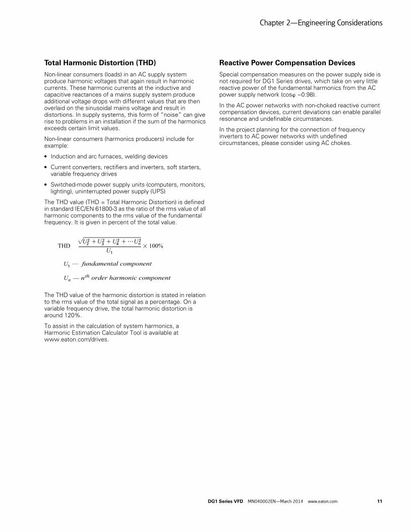
Non-linear consumers (loads) in an AC supply system produce harmonic voltages that again result in harmonic currents. These harmonic currents at the inductive and capacitive reactances of a mains supply system produce additional voltage drops with different values that are then overlaid on the sinusoidal mains voltage and result in distortions. In supply systems, this form of “noise” can give rise to problems in an installation if the sum of the harmonics exceeds certain limit values.
Non-linear consumers (harmonics producers) include for example:
● Induction and arc furnaces, welding devices
● Current converters, rectifiers and inverters, soft starters, variable frequency drives
● Switched-mode power supply units (computers, monitors, lighting), uninterrupted power supply (UPS)
The THD value (THD = Total Harmonic Distortion) is defined in standard IEC/EN 61800-3 as the ratio of the rms value of all harmonic components to the rms value of the fundamental frequency. It is given in percent of the total value.
The THD value of the harmonic distortion is stated in relation to the rms value of the total signal as a percentage. On a variable frequency drive, the total harmonic distortion is around 120%.
To assist in the calculation of system harmonics, a Harmonic Estimation Calculator Tool is available at www.eaton.com/drives.
Reactive Power Compensation Devices
Special compensation measures on the power supply side is not required for DG1 Series drives, which take on very little reactive power of the fundamental harmonics from the AC power supply network (cosw ~0.98).
In the AC power networks with non-choked reactive current compensation devices, current deviations can enable parallel resonance and undefinable circumstances.
In the project planning for the connection of frequency inverters to AC power networks with undefined circumstances, please consider using AC chokes.
fundamental component
;U U U UU
U
U
???3 100%+
—
—
+ +THD n
n order harmonic componentnth
3 42
1
1
2222

Chapter 3—Product Overview
12 DG1 Series VFD MN040002EN—March 2014 www.eaton.com
Chapter 3—Product Overview
Component Identification
Figure 6. Description of the DG1 Series
Features
The DG1 frequency inverter converts the voltage and frequency of an existing AC network into a DC voltage. This DC voltage is used to generate a three-phase AC voltage with adjustable frequency and assigned amplitude values for the variable speed control of three-phase asynchronous motors.

Chapter 3—Product Overview
DG1 Series VFD MN040002EN—March 2014 www.eaton.com 13
Figure 7. Block Diagram, Elements of DG1 Frequency Inverters
Table 12. Elements of DG1 Frequency Inverters
Item No. Description
1 Supply L1, L2 L3, PE, input supply voltage ULN = Ue at 50/60 Hz:
DG1-32: 230V class, three-phase input connection (3 AC 230V/240V)
DG1-34: 400V class, three-phase input connection (3 AC 400V/480V)
2 Internal interference suppression filter, category C2 to IEC/EN 61800-3
EMC-connection of internal interference suppression filter to PE
3 Rectifier bridge, converts the AC voltage of the electrical network into DC voltage
4 DC link with charging resistor, capacitor and switching mode power supply unit
(SMPS = Switching Mode Power Supply):
DC link voltage UDC with three-phase input connection (3 AC): UDC = 1.41 x ULN
5 Inverter. The IGBT based inverter converts the DC voltage of the DC link (UDC) into a three-phase AC voltage (U2) with variable amplitude and frequency (f2). Sinusoidal pulse width modulation (PWM) with V/f control can be switched to speed control with slip compensation
6 Motor connection U/T1, V/T2, W/T3 with output voltage U2 (0–100% Ue) and output frequency f2 (0–400 Hz) output current (I2):
DG1-32: 3.7A to 261A
DG1-34: 2.2A to 261A
100% at an ambient temperature of 122°F (50°C) with an overload capacity of 150% for 60 s every 600 s and a starting current of 200% for 2 s every 20 s
7 Keypad with control buttons, graphic display, control voltage, control signal terminals, micro-switches, and interface for the PC interface module (option)
8 Three-phase asynchronous motor, variable speed control of three-phase asynchronous motor for assigned motor shaft power values (P2):
DG1-32: 0.55 kW to 75 kW (230V, 50 Hz) or 0.75 hp to 100 hp (240V, 60 Hz)
DG1-34: 0.75 kW to 150 kW (400V, 50 Hz) or 1 hp to 200 hp (460V, 60 Hz)
9 DC link—chokes, to minimize current harmonics

Chapter 3—Product Overview
14 DG1 Series VFD MN040002EN—March 2014 www.eaton.com
Selection Criteria
The frequency inverter [3] is selected according to the supply voltage ULN of the input supply [1] and the rated current of the assigned motor [2]. The circuit type (P/k) of the motor must be selected according to the supply voltage [1]. The rated output current Ie of the frequency inverter must be greater than/equal to the rated motor current.
Figure 8. Selection Criteria
When selecting the drive, the following criteria must be known:
● Type of motor (three-phase asynchronous motor)
● Input voltage = rated operating voltage of the motor (for example, 3 AC ~400V)
● Rated motor current (guide value, dependent on the circuit type and the supply voltage)
● Load torque (quadratic, constant)
● Starting torque
● Ambient temperature (rated value 122°F [50°C])
When connecting multiple motors in parallel to the output of a frequency inverter, the motor currents are added geometrically—separated by effective and idle current components. When you select a frequency inverter, make sure that it can supply the total resulting current. If necessary, for dampening and compensating the deviating current values, motor reactors or sinusoidal filters must be connected between the frequency inverter and the motor.
The parallel connection of multiple motors in the output of the frequency inverter is only permitted with V/Hz characteristic curve control.
If you connect a motor to an operational frequency inverter, the motor draws a multiple of its rated operational current. When you select a frequency inverter, make sure that the starting current plus the sum of the currents of the running motors will not exceed the rated output current of the frequency inverter.
Switching in the output of the frequency inverter is only permitted with V/Hz characteristic curve control.
Proper Use
The DG1 frequency inverters are electrical apparatus for controlling variable speed drives with three-phase motors. They are designed for installation in machines or for use in combination with other components within a machine or system.
After installation in a machine, the frequency inverters must not be taken into operation until the associated machine has been confirmed to comply with the safety requirements of Machinery Safety Directive (MSD) 89/392/EEC (meets the requirements of EN 60204). The user of the equipment is responsible for ensuring that the machine use complies with the relevant EU Directives.
The CE markings on the DG1 frequency inverter confirm that, when used in a typical drive configuration, the apparatus complies with the European Low Voltage Directive (LVD) and the EMC Directives (Directive 2006/95/EC and Directive 2004/108/EC).
In the described system configurations, DG1 frequency inverters are suitable for use in public and non-public networks.
A connection to IT networks (networks without reference to earth potential) is permissible only to a limited extent, because the device’s built-in filter capacitors connect the network with the earth potential (enclosure). On earth free networks, this can lead to dangerous situations or damage to the device (isolation monitoring required).
To the output of the frequency inverter (terminals U, V, W) you must not:
● connect a voltage or capacitive loads (for example, phase compensation capacitors)
● connect multiple frequency inverters in parallel
● make a direct connection to the input (bypass)
Observe the technical data and connection requirements. For additional information, refer to the equipment nameplate or label at the frequency inverter, and the documentation.
Any other usage constitutes improper use.

Chapter 3—Product Overview
DG1 Series VFD MN040002EN—March 2014 www.eaton.com 15
Maintenance and Inspection
DG1 frequency inverters are maintenance free. However, external influences may affect the function and the lifespan of the DG1 frequency inverter. We therefore recommend that the devices are checked regularly and the following maintenance measures are carried out at the specified intervals.
If the DG1 frequency inverter is damaged by external influences, contact Eaton Technical Service.
Table 13. Maintenance Measures and Intervals
Storage
If the frequency inverter is stored before use, suitable ambient conditions must be ensured at the site of storage:
● Storage temperature: –40°F to 158°F (–40°C to 70°C)
● Relative average air humidity: <95%, noncondensing (EN 50178)
● To prevent damage to the DC link capacitors, storage times longer than 12 months are not recommended
Charging the Internal DC Link Capacitors
After extended storage times or extended downtimes during which no power is supplied (>12 months), the capacitors in the internal DC link must be recharged in a controlled manner in order to prevent damage. To do this, the DG1 variable frequency drive must be supplied with power, with a controlled DC power supply unit, via two mains DC bus connection terminals. Please consult the factory for detailed instructions.
Service and Warranty
In the unlikely event that you have a problem with your DG1 frequency inverter, please contact your local sales office.
When you call, have the following information ready:
● the exact frequency inverter part no. (see nameplate)
● the date of purchase
● a detailed description of the problem that has occurred with the frequency inverter
If some of the information printed on the nameplate is not legible, please state only the information that is clearly legible. This information can also be found on the cover of the control terminals.
Information concerning the guarantee can be found in the Eaton General Terms and Conditions of Sale.
Maintenance Measure Maintenance Interval
Clean cooling vents (cooling slits) If required
Check the fan function 6–24 months (depending on the environment)
Filter in the switching cabinet doors (see manufacturer specifications)
6–24 months (depending on the environment)
Check the tightening torques of the terminals (control signal terminals, power terminals)
Regularly
Check connection terminals and all metallic surfaces for corrosion
6–24 months (depending on the environment)

Chapter 4—Safety and Switching
16 DG1 Series VFD MN040002EN—March 2014 www.eaton.com
Chapter 4—Safety and Switching
Fuses and Cable Cross-Sections
The fuses and wire cross-sections allocated for power-side connections depend on the rated input current and output current of the frequency inverter (without AC choke).
CAUTIONWhen selecting the cable cross-section, take the voltagedrop under load conditions into account.
The consideration of other standards (for example, VDE 0113 or VDE 0289) is the responsibility of the user.
The national and regional standards (for example VDE 0113, EN 60204) must be observed and the necessary approvals (for example UL) at the site of installation must be fulfilled.
When the device is operated in a UL-approved system, use only UL-approved fuses, fuse bases, and cables.
See Appendix D—Safety Instructions for UL and cUL for details.
CAUTIONThe specified minimum PE conductor cross-sections in thismanual must be maintained. The minimum size of theprotective earthing conductor must comply with therequirements of EN 61800-5-1 and/or the local safetyregulations.
Touch currents in this frequency inverter are greater than 3.5 mA (AC). According to product standard IEC/EN 61800-5-1, an additional equipment grounding conductor of the same cross-sectional area as the original protective earthing conductor must be connected, or the cross-section of the equipment grounding conductor must be at least 10 mm2 Cu.
Choose the cross-section of the PE conductor in the motor lines at least as large as the cross-section of the phase lines (U, V, W).
Cables and Fuses
The cross-sections of the cables and line protection fuses used must correspond with local standards.
For an installation in accordance with UL guidelines:
● Use UL recognized Class T fuses for the branch circuit protection
● Use 75°C copper wire only
● Use UL listed conduit fittings with the same type rating (Type 1/Type 12) as the enclosure
See Appendix D—Safety Instructions for UL and cUL for details.
Use power cables with insulation according to the specified input voltages for the permanent installation. A shielded cable is not required on the input side.
A completely (360°) shielded low impedance cable is required on the motor side. The length of the motor cable depends on the RFI class and must not exceed approximately 300 ft (100m) without additional filtering.
Residual-Current Device (RCD)
RCD (Residual Current Device): Residual current device, residual current circuit breaker (FI circuit breaker).
Residual current circuit breakers protect persons and animals from the existence (not the origination) of impermissibly high contact voltages. They prevent dangerous, and in some cases deadly injuries caused by electrical accidents, and also serve as fire prevention.
CAUTIONThis drive can cause a DC current in the protective earthingconductor. Where a residual current-operated protective(RCD) or monitoring (RCM) device is used for protection incase of direct or indirect contact, only an RCD or RCM ofType B is allowed on the supply side of this product.
Figure 9. Identification on the FI Circuit Breakers
Frequency inverters work internally with rectified AC currents. If an error occurs, the DC currents can block a type A RCD circuit breaker from triggering and therefore disable the protective functionality.
CAUTIONDebounced inputs may not be used in the safety circuitdiagram.
Residual current circuit breakers (RCD) are only to be installed between the AC power supply network and the frequency inverter.
AC/DC sensitive(RCD, type B)

Chapter 4—Safety and Switching
DG1 Series VFD MN040002EN—March 2014 www.eaton.com 17
Safety-relevant leakage currents can occur while handling and when operating the frequency inverter, if the frequency inverter is not grounded (because of a fault).
Leakage currents to ground are mainly caused by foreign capacities with frequency inverters, between the motor phases and the shielding of the motor cable and via the Y-capacitors of the RFI filter. The size of the leakage current is mainly dependent upon the:
● length of the motor cable
● shielding of the motor cable
● height of the switching frequency of the inverter
● design of the RFI filter
● grounding measures at the site of the motor
The leakage current to ground is greater than 3.5 mA with a frequency inverter. According to product standard IEC/EN 61800-5-1, an additional equipment grounding (PE) conductor of the same cross-sectional area as the original protective earthing conductor must be connected, or the cross-section of the equipment grounding conductor must be at least 10 mm2 Cu.
Residual current circuit breakers must be suitable for:
● the protection of installations with DC current component in case of fault scenario (RCD type B)
● high leakage currents
● brief discharges of pulse current spikes
Input Contactor
The input contactor enables an operational switching on and off of the supply voltage for the frequency inverter, and switching off in case of a fault.
The input contactor is designed based on the input current (ILN) of the frequency inverter and the utilization category AC-1 (IEC 60947). Input contactors and the assignment to DG1 frequency inverters are explained in Appendix A.
While planning the project, make sure that inching operation is not done via the input contactor of the frequency inverter on frequency-controlled drives, but through a controller input of the frequency inverter.
The maximum permitted operating frequency of the input voltage with the DG1 frequency inverter is one time per minute (normal operation).

Chapter 4—Safety and Switching
18 DG1 Series VFD MN040002EN—March 2014 www.eaton.com
EMC Measures
Electrical components in a system (machine) have an interaction effect on each other. Each device not only emits interference but is also affected by it. The interference can be produced by galvanic, capacitive, and/or inductive sources, or by electromagnetic radiation. In practice, the limit between line-conducted interference and radiated emitted interference is around 30 MHz. Above 30 MHz, cables and conductors act like antennas that radiate electromagnetic waves.
Electromagnetic compatibility (EMC) for frequency controlled drives (variable frequency drives) is implemented in accordance with product standard IEC/EN 61800-3. This includes the complete power drive system (PDS), from the input supply to the motor, including all components, as well as cables. This type of drive system can consist of several individual drives.
The generic standards of the individual components in a PDS compliant with IEC/EN 61800-3 do not apply. These component manufacturers, however, must offer solutions that ensure standards-compliant use.
In Europe, maintaining the EMC guidelines is mandatory.
A declaration of conformity (CE) always refers to a “typical” power drive system (PDS). The responsibility to comply with the legally stipulated limit values and thus the provision of electromagnetic compatibility is ultimately the responsibility of the end user or system operator. This operator must also take measures to minimize or remove emission in the environment concerned (see Figure 10). He must also use means to increase the interference immunity of the devices of the system.
With their high interference immunity up to category C2, DG1 frequency inverters are ideal for use in commercial networks (1st environment).
Table 14. Maximum Motor Cable Length by Frame Size without dV/dT Protected C2 Ratings
Figure 10. EMC Measures
Frame Size Maximum Cable Length (m)
FR1 100
FR2 150
FR3 150
FR4 200
FR5 200
Low Voltage Supply Grid
1 Environmentst
Category C1 Category C1/C2
Low Voltage Supply Grid
2 Environmentnd
Category C3/C4
Chapter 5—Motor and Application
DG1 Series VFD MN040002EN—March 2014 www.eaton.com 19
Chapter 5—Motor and Application
Motor Selection
General recommendations for motor selection:
● Use three-phase powered asynchronous motors with short-circuit rotors and surface cooling, also called inverter motors or standard motors for the frequency-controlled drive system (PDS). Other specifications such as external rotor motors, slip-ring motors, reluctance motors, synchronous or servo motors can also be run with a frequency inverter, but normally require additional planning and discussion with the motor manufacturer.
● Use only motors with at least heat class F (311°F [155°C] maximum steady state temperature).
● Four-pole motors are preferred (synchronous speed: 1500 min–1 at 50 Hz or 1800 min–1 at 60 Hz).
● Take the operating conditions into account for S1 operation (IEC 60034-1).
● When operating multiple motors in parallel on one frequency inverter, the motor output should not be more than three power classes apart.
● Ensure that the motor is not over-dimensioned. If a motor in speed control mode is under-dimensioned, the motor rating must only be one rating level lower.
Connecting Motors in Parallel
The DG1 frequency inverters allow parallel operation of several motors using multi-pump application control mode:
● Multi-pump application: several motors with the same or different rated operational data. The sum of all motor currents must be less than the frequency inverter’s rated operational current.
● Multi-pump application: parallel control of several motors. The sum of the motor currents plus the motors’ inrush currents must be less than the frequency inverter’s rated operational current.
Parallel operation at different motor speeds can be implemented only by changing the number of pole pairs and/ or changing the motor’s transmission ratio.
CAUTIONDebounced inputs may not be used in the safety circuitdiagram.
If you are connecting multiple motors on one frequency inverter, you must design the contactors for the individual motors according to utilization category AC-3.
Selecting the motor contactor is done according to the rated operational current of the motor to be connected.

Chapter 5—Motor and Application
20 DG1 Series VFD MN040002EN—March 2014 www.eaton.com
Parallel Connection of Several Motors to One Frequency Inverter
Figure 11. Parallel Connection
Connecting motors in parallel reduces the load resistance at the frequency inverter output. The total stator inductance is lower and the leakage capacity of the lines greater. As a result, the current distortion is greater than in a single-motor circuit. To reduce the current distortion, you should use motor reactors (see 1 in Figure 11) in the output of the frequency inverter.
The current consumption of all motors connected in parallel must not exceed the frequency inverter’s rated output current I2N.
Electronic motor protection cannot be used when operating the frequency inverter with several parallel connected motors. You must, however, protect each motor with thermistors and/or overload relays.
The use of a motor protective circuit breaker at the frequency inverter’s output can lead to nuisance tripping.
Motor and Circuit Type
The motor’s stator winding can be connected in a star or delta configuration, in accordance with the rated operational data on the nameplate.
Figure 12. Example of a Motor Ratings Plate
Figure 13. Star and Delta Circuit Types
The three-phase motor with the rating plate based on Figure 13, can be run in a star or delta connection. The operational characteristic curve is determined by the ratio of motor voltage and motor frequency, in this case.
87 Hz Characteristic Curve
In the delta circuit with 400V and 87 Hz, the motor shown in Figure 13 was released with three times-fold output (~1.3 kW).
Because of the higher thermal loading, using only the next higher motor output according to the list (1.1 kW) is recommended. The motor (in this example) therefore still has 1.47-fold higher output compared with the listed output (0.75 kW).
With the 87 Hz characteristic curve, the motor also works in the range from 50 Hz to 87 Hz with an un-attenuated field. The pull-out torque remains at the same level as in input operation with 50 Hz.
The heat class of the motor must be at least F in 87 Hz operation.

Chapter 5—Motor and Application
DG1 Series VFD MN040002EN—March 2014 www.eaton.com 21
V/Hz Characteristic Curve
Figure 14. V/Hz Characteristic Curve
Table 15 shows the allocation of possible frequency inverters depending on the input voltage and the type of circuit.
Table 15. Assignment of Frequency Inverters to Example Motor Circuit (See Figure 14)
Notes1 Star connection: 400V, 50 Hz.2 Delta connection: 230V, 50 Hz.3 Delta connection: 400V, 87 Hz.4 Note the permitted limit values of the motor.
Frequency Inverters DG1-323D7FB DG1-343D3FB DG1-344D3FB
Rated operational current 3.7A 3.3A 4.3A
Input voltage 3 AC, 230V 3 AC, 400V 3 AC, 400V
Motor circuit Delta Star Delta
V/Hz characteristic curve 2 1 3
Motor current 3.5A 2.0A 3.5A
Motor voltage (ratings plate) 230V 400V 230V
Motor speed 1430 min-1 1430 min-1 2474 min-1 4
Motor frequency 50 Hz 50 Hz 87 Hz 3

Chapter 5—Motor and Application
22 DG1 Series VFD MN040002EN—March 2014 www.eaton.com
Bypass Operation
If you want to have the option of operating the motor with the frequency inverter or directly from the input supply, the input branches must be interlocked mechanically.
CAUTIONDebounced inputs may not be used in the safety circuitdiagram.
A changeover between the frequency inverter and the input supply must take place in a voltage-free state.
WARNINGThe frequency inverter outputs (U, V, W) must not beconnected to the input voltage (destruction of thedevice, risk of fire).
Figure 15. Bypass Motor Control (Example)
Table 16. Bypass Motor Control
CAUTIONDebounced inputs may not be used in the safety circuitdiagram.
Switch S1 must switch only when frequency inverter T1 is at zero current.
Contactors and switches (S1) in the frequency inverter output and for the direct start must be designed based on utilization category AC-3 for the rated operational current of the motor.
Connecting EX Motors
Note the following when connecting explosion-protected motors:
● The frequency inverter must be installed outside the EX area.
● Note the branch- and country-specific standards for explosion-protected areas (ATEX 100a).
● Note the standards and information of the motor manufacturer regarding operation on frequency inverters— for example, if motor reactors or sine-wave filters are specified.
● Temperature monitors in the motor windings (thermistor, thermo-Click) are not to be connected directly to frequency inverters but must be connected via an approved trigger apparatus for EX areas.
Item No. Description
1 Input/bypass contactor
2 Output contactor
Q1
I> I>I>
Q11
S1
M1
T1
M 3~
L1 L2 L3
L1 L2 L3
U V W

Chapter 6—Installation Requirements
DG1 Series VFD MN040002EN—March 2014 www.eaton.com 23
Chapter 6—Installation Requirements
This chapter contains all of the information required to properly install and prepare the DG1 Series VFD for operation. The contents are listed to serve as a list of tasks needed to complete the installation. Included in this section are:
● Line (mains) and motor power wiring
● I/O control wiring
Electrical Installation Warnings and Cautions
WARNINGCarry out wiring work only after the frequency inverterhas been correctly mounted and secured.
WARNINGElectric shock hazard—risk of injuries!
Carry out wiring work only if the unit is de-energized.
CAUTIONDebounced inputs may not be used in the safety circuitdiagram.
Fire hazard!
Only use cables, protective switches, and contactors thatfeature the indicated permissible nominal current value.
CAUTIONDebounced inputs may not be used in the safety circuitdiagram.
According to product standard IEC/EN 61800-5-1, anadditional equipment grounding (PE) conductor of the samecross-sectional area as the original protective earthingconductor must be connected, or the cross-section of theequipment grounding conductor must be at least 10 mm2 Cu.
WARNINGThe components in the drive’s power section remainenergized after the supply voltage has been switched off.After disconnecting the supply, wait at least five minutesbefore removing the cover to allow the intermediatecircuit capacitors to discharge.
Pay attention to hazard warnings!
Standard Mounting Instructions ● Select the mounting location based on requirements listed
in this chapter
● Mounting surface must be a vertical, flat, non-flammable surface
● DG1 Series open drives may be mounted side-by-side or stacked vertically, as outlined in this chapter
● Surface must be strong enough to support the drive and not subject to excessive motion or vibration
● Mark the location of the mounting holes on the mounting surface (“using the template provided on the cover of the cardboard shipping package”,
● Using fasteners appropriate to your VFD and mounting surface, securely attach the VFD to the mounting surface using all four mounting hole locations
When mounting one unit above the other, the lower unit air outlet must be directed away from the inlet air used by the upper one. The clearance between the upper and lower unit should equal C + D. See Figure 16 on next page.
1. Measure the mounting space to ensure that it allows the minimum space surrounding the VFD Series drive. Drive dimensions are on Appendix C.
2. Make sure the mounting surface is flat and strong enough to support the drive, is not flammable, and is not subject to excessive motion or vibration.
3. Ensure that the minimum airflow requirements for your drive are met at the mounting location.
4. Mark the location of the mounting holes on the mounting surface, using the template provided on the cover of the cardboard shipping package.
5. Using fasteners appropriate to your drive and mounting surface, securely attached the drive to the mounting surface using all four screws or bolts.
Mounting Dimensions
Refer to Appendix C for drive dimensions.
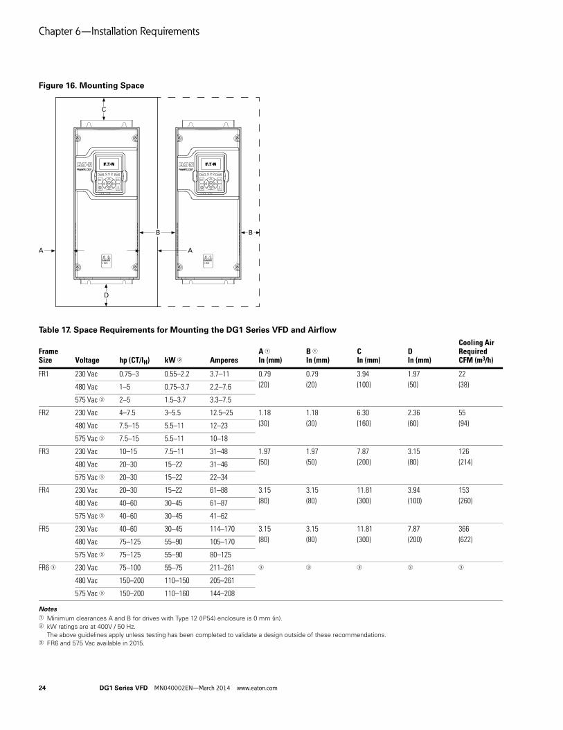
Chapter 6—Installation Requirements
24 DG1 Series VFD MN040002EN—March 2014 www.eaton.com
Figure 16. Mounting Space
Table 17. Space Requirements for Mounting the DG1 Series VFD and Airflow
Notes1 Minimum clearances A and B for drives with Type 12 (IP54) enclosure is 0 mm (in). 2 kW ratings are at 400V / 50 Hz.
The above guidelines apply unless testing has been completed to validate a design outside of these recommendations.3 FR6 and 575 Vac available in 2015.
Frame Size Voltage hp (CT/IH) kW 2 Amperes
A 1
In (mm)B 1
In (mm)CIn (mm)
DIn (mm)
Cooling Air RequiredCFM (m3/h)
FR1 230 Vac 0.75–3 0.55–2.2 3.7–11 0.79
(20)
0.79
(20)
3.94
(100)
1.97
(50)
22
(38)480 Vac 1–5 0.75–3.7 2.2–7.6
575 Vac 3 2–5 1.5–3.7 3.3–7.5
FR2 230 Vac 4–7.5 3–5.5 12.5–25 1.18
(30)
1.18
(30)
6.30
(160)
2.36
(60)
55
(94)480 Vac 7.5–15 5.5–11 12–23
575 Vac 3 7.5–15 5.5–11 10–18
FR3 230 Vac 10–15 7.5–11 31–48 1.97
(50)
1.97
(50)
7.87
(200)
3.15
(80)
126
(214)480 Vac 20–30 15–22 31–46
575 Vac 3 20–30 15–22 22–34
FR4 230 Vac 20–30 15–22 61–88 3.15
(80)
3.15
(80)
11.81
(300)
3.94
(100)
153
(260)480 Vac 40–60 30–45 61–87
575 Vac 3 40–60 30–45 41–62
FR5 230 Vac 40–60 30–45 114–170 3.15
(80)
3.15
(80)
11.81
(300)
7.87
(200)
366
(622)480 Vac 75–125 55–90 105–170
575 Vac 3 75–125 55–90 80–125
FR6 3 230 Vac 75–100 55–75 211–261 3 3 3 3 3
480 Vac 150–200 110–150 205–261
575 Vac 3 150–200 110–160 144–208
A
C
D
B B
A

Chapter 6—Installation Requirements
DG1 Series VFD MN040002EN—March 2014 www.eaton.com 25
Dimensions
Approximate Dimensions in mm
Figure 17. Type 1/12 Open Drives
Note1 FR6 and 575 Vac available in 2015.
Table 18. Mounting Drive Dimensions
Frame Size Voltage hp (CT/IH) kW
Amperes(CT/IH)
Approximate Dimensions in Inches (mm)Weight Lb (kg)D H1 H2 H3 W1 W2 W3 W4 Ø
FR1 230 Vac 0.75–3 0.55–2.2 3.5–11 7.89(200.4)
12.87(326.9)
12.28(311.9)
11.50(292.1)
6.02(153.0)
4.80(121.9)
3.94(100.1)
3.94(100.1)
0.28(7.0)
14.33(6.5)480 Vac 1–5 0.75–3.7 2.3–7.6
575 Vac 1 2–5 1.5–3.7 3.3–7.5
FR2 230 Vac 5–7.5 3–5.5 12.5–25 9.63(244.7)
16.50(419.1)
15.98(405.9)
14.96(380.0)
6.61(167.8)
5.28(134.1)
3.54(90.0)
3.54(90.0)
0.28(7.0)
23.37(10.6)480 Vac 7.5–15 5.5–11 12–23
575 Vac 1 7.5–15 5.5–11 10–18
FR3 230 Vac 10–15 7.5–11 31–48 10.44(265.1)
21.97(558.0)
21.46(545.0)
20.43(518.9)
8.06(204.6)
7.24(183.9)
4.92(125.0)
4.92(125.0)
0.35(9.0)
49.82(22.6)480 Vac 20–30 15–22 31–46
575 Vac 1 20–30 15–22 22–34
FR4 230 Vac 20–30 15–22 61–88 11.57(294.0)
24.80(629.9)
34.31(617.5)
23.27(591.1)
9.36(237.7)
9.13(231.9)
8.07(205.0)
8.07(205.0)
0.35(9.0)
77.60(35.2)480 Vac 40–60 30–45 61–87
575 Vac 1 40–60 30–45 41–62
FR5 230 Vac 40–60 30–45 114–170 13.41(340.7)
34.98(888.5)
29.65(753.1)
27.83(706.9)
11.34(288.0)
11.10(281.9)
8.66(220.0)
8.66(220.0)
0.35(9.0)
154.32(70.0)480 Vac 75–125 55–90 105–170
575 Vac 1 75–125 55–90 80–125
FR6 1 230 Vac 75–100 55–75 211–261 1 1 1 1 1 1 1 1 1 1
480 Vac 150–200 110–150 205–261
575 Vac 1 150–200 110–160 144–208
W3
H2
W4
W1
W2
H1
D
H3

Chapter 6—Installation Requirements
26 DG1 Series VFD MN040002EN—March 2014 www.eaton.com
Standard Drive Mounting
FR1 Mounting Instructions
Step 1: Lift the drive out from the carton. Remove the packaging.
Step 2: Attach the drive to the mounting plate with four M5x15 or 3/16 inch screws and four M5 or 3/16 inch nuts. The opening dimensions on the mounting plate should follow required dimensions (refer to the drive mounting template printed on the outside carton).
FR2 Mounting Instructions
Step 1: Lift the drive out from the carton. Remove the packaging.
Step 2: Attach the drive to the mounting plate with four M5x15 or 3/16 inch screws and four M5 or 3/16 inch nuts. The opening dimensions on the mounting plate should follow required dimensions (refer to the drive mounting template printed on the outside carton).
Screw: Four M5x15or 3/16 inch
Nut: Four M5or 3/16 inch Screw: Four M5x15
or 3/16 inch
Nut: Four M5or 3/16 inch
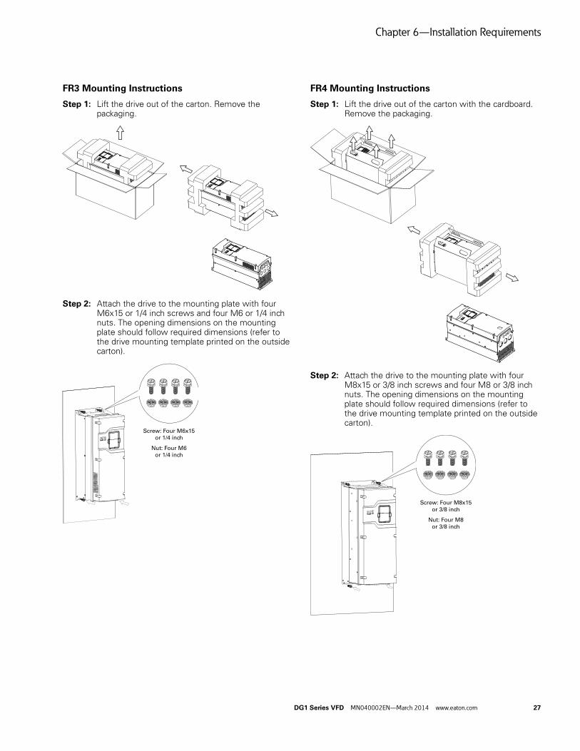
Chapter 6—Installation Requirements
DG1 Series VFD MN040002EN—March 2014 www.eaton.com 27
FR3 Mounting Instructions
Step 1: Lift the drive out of the carton. Remove the packaging.
Step 2: Attach the drive to the mounting plate with four M6x15 or 1/4 inch screws and four M6 or 1/4 inch nuts. The opening dimensions on the mounting plate should follow required dimensions (refer to the drive mounting template printed on the outside carton).
FR4 Mounting Instructions
Step 1: Lift the drive out of the carton with the cardboard. Remove the packaging.
Step 2: Attach the drive to the mounting plate with four M8x15 or 3/8 inch screws and four M8 or 3/8 inch nuts. The opening dimensions on the mounting plate should follow required dimensions (refer to the drive mounting template printed on the outside carton).
Screw: Four M6x15or 1/4 inch
Nut: Four M6or 1/4 inch
Screw: Four M8x15or 3/8 inch
Nut: Four M8or 3/8 inch

Chapter 6—Installation Requirements
28 DG1 Series VFD MN040002EN—March 2014 www.eaton.com
FR5 Mounting Instructions
Step 1: Remove the carton from the drive.
Step 2: Remove the four screws (used to fix the drive to the pallet) with an M8 or 3/8 inch wrench.
Step 3: Use a hook to lift the drive.
Step 4: Attach the drive to the mounting plate with four M8x20 or 3/8 inch screws and four M8 or 3/8 inch nuts with an M8 or 3/8 inch wrench. The opening dimensions on the mounting plate should follow required dimensions (refer to the drive mounting template printed on the outside carton).
Screw: Four M8x20or 3/8 inch
Nut: Four M8or 3/8 inch

Chapter 6—Installation Requirements
DG1 Series VFD MN040002EN—March 2014 www.eaton.com 29
Power Wiring Selection
Motor cable connections are made to terminals U, V, and W.
Cable Selection: Power and Motor Leads ● Use UL approved heat-resistant copper cables only
● 75°C or higher for all units rated
● Line voltage/mains should be Class 1 wire only outside North America
● Refer to the following tables for cable sizing guidelines
● North America 208V to 240V: Appendix B
● North America 380V to 500V: Appendix B
● All other International 380V to 600V: Appendix B
Line (Mains) and Motor Cable Installation
The input line and motor cables must be sized in accordance with the rated DG1 VFD input and output current.
If motor temperature sensing is used for overload protection, the output cable size may be selected based on the motor specifications.
Maximum symmetrical supply current is 100,000A RMS for all size DG1 VFDs.
Input Fusing
Fuses are rated based on DG1 rated input and output current. Use Class T (UL and cUL/CSA®) or type gG/gL (IEC 60269-1). Refer to Appendix B for proper fuse size selection.
Consult with Eaton Electrical for further information on fusing requirements.
Connection Tightening Torque
Table 19. Tightening Torque 1 2
Notes1 Strip the motor and power cables as shown in Figure 18 on next page. 2 Both UL and IEC tools may be used. 3 Applies to strained wire, solid wire, or ferrule installations.
Table 20. Spacing Between Parallel Motor Cables
Table 21. Maximum Motor Cable Length by Frame Size without dV/dT Protected C2 Ratings 1 2
Notes1 C1 protection requires external filtering. Consult factory.b C3 protection is covered under C2 protection levels.
Frame Size
Power WireIn-Lb (Nm)
Ground WireIn-Lb (Nm)
Control Wire 3
In-Lb (Nm)
FR1 230V: 12.1 (1.4)
480V/575V: 5.5 (0.6)
10 (1.1) 4.5 (0.5)
FR2 15.6 (1.8) 10 (1.1) 4.5 (0.5)
FR3 40 (4.5) 10 (1.1) 4.5 (0.5)
FR4 95 (10.7) 14 (1.6) 4.5 (0.5)
FR5 354 (40) 35 (4.0) 4.5 (0.5)
FR6 Available in 2015 — —
Cable Length Distance Between Cables
Less than 164 ft (50m) 1 ft (0.3 m)
Less than 657 ft (200m) 3 ft (1.0 m)
Frame Size Maximum Cable Length (m)
FR1 100
FR2 150
FR3 150
FR4 200
FR5 200
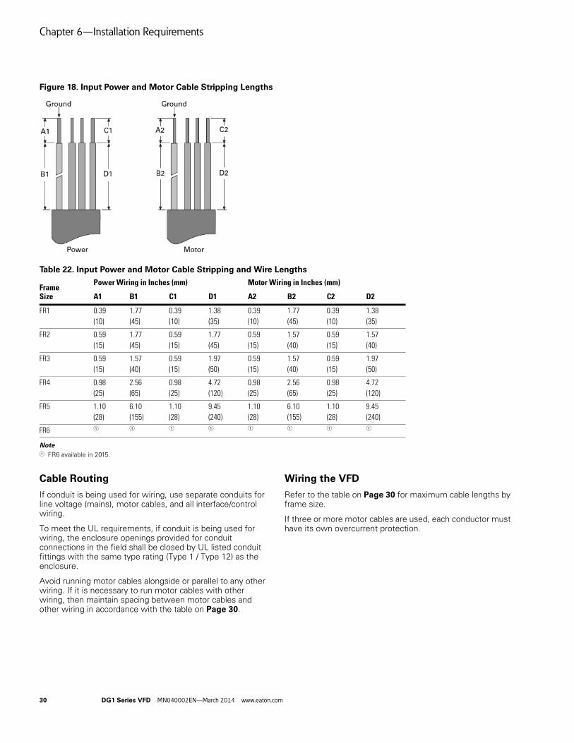
Chapter 6—Installation Requirements
30 DG1 Series VFD MN040002EN—March 2014 www.eaton.com
Figure 18. Input Power and Motor Cable Stripping Lengths
Table 22. Input Power and Motor Cable Stripping and Wire Lengths
Note1 FR6 available in 2015.
Cable Routing
If conduit is being used for wiring, use separate conduits for line voltage (mains), motor cables, and all interface/control wiring.
To meet the UL requirements, if conduit is being used for wiring, the enclosure openings provided for conduit connections in the field shall be closed by UL listed conduit fittings with the same type rating (Type 1 / Type 12) as the enclosure.
Avoid running motor cables alongside or parallel to any other wiring. If it is necessary to run motor cables with other wiring, then maintain spacing between motor cables and other wiring in accordance with the table on Page 30.
Wiring the VFD
Refer to the table on Page 30 for maximum cable lengths by frame size.
If three or more motor cables are used, each conductor must have its own overcurrent protection.
Frame Size
Power Wiring in Inches (mm) Motor Wiring in Inches (mm)
A1 B1 C1 D1 A2 B2 C2 D2
FR1 0.39
(10)
1.77
(45)
0.39
(10)
1.38
(35)
0.39
(10)
1.77
(45)
0.39
(10)
1.38
(35)
FR2 0.59
(15)
1.77
(45)
0.59
(15)
1.77
(45)
0.59
(15)
1.57
(40)
0.59
(15)
1.57
(40)
FR3 0.59
(15)
1.57
(40)
0.59
(15)
1.97
(50)
0.59
(15)
1.57
(40)
0.59
(15)
1.97
(50)
FR4 0.98
(25)
2.56
(65)
0.98
(25)
4.72
(120)
0.98
(25)
2.56
(65)
0.98
(25)
4.72
(120)
FR5 1.10
(28)
6.10
(155)
1.10
(28)
9.45
(240)
1.10
(28)
6.10
(155)
1.10
(28)
9.45
(240)
FR6 1 1 1 1 1 1 1 1

Chapter 6—Installation Requirements
DG1 Series VFD MN040002EN—March 2014 www.eaton.com 31
Power Wiring Notice
Do not discard the plastic bag containing the wiring hardware.
1. Remove the A-cover by removing (4) screws, then lifting the A-cover away from the base.
Wiring Hardware Contents ● European rubber grommet and flat rubber grommet
(for IP54 integrity)
● Modification label
● Detachable cable clamp
● Attachable grounding strap
● Ground strap mounting screws
Power Wiring/Grounding 2. Remove power wiring protection plate. Use power/
motor cable tables on Appendix B.
3. Add attachable grounding clamps (qty 2), one on each side of drive.
4. Pass motor, input power wires/cables through base wiring plate.
5. If shielded cable is used, connect the shields of input power and motor cables shields to ground.
6. Wire power terminals (L1, L2, L3), motor terminal (U, V, W), and grounding terminals per Figure 19. Power and motor leads must be in separate conduit.
To meet the UL requirements, if conduit is being used for wiring, the enclosure openings provided for conduit connections in the field shall be closed by UL listed conduit fittings with the same type rating (Type 1/Type 12) as the enclosure.

Chapter 6—Installation Requirements
32 DG1 Series VFD MN040002EN—March 2014 www.eaton.com
Rubber Grommet Installation Instructions
Step 1: Measure the outside diameter of the cable (D1) used to connect to the drive.
Step 2: Measure the outside diameter of the rubber grommet (D2) and select a suitable D2 (D1 ≤ D2 ≤ D1 + 2 mm).
Step 3: Cut the rubber grommet at the selected diameter.
Step 4: Run the cable through the rubber grommet.
Step 5: Insert the rubber grommet into the conduit plate together with the cable.
Step 6: Fasten the rubber grommet and cable with a self-locking cable tie.
D1 (Cable)
D2 (Grommet)
D1 ≤ D2 ≤ D1 + 2 mm
Self-Locking Cable Ties

Chapter 6—Installation Requirements
DG1 Series VFD MN040002EN—March 2014 www.eaton.com 33
Figure 19. Ground Wiring
Note: Do not wire motor leads to R+, R–. This will cause damage to the drive.
Note: Actual layout may vary slightly by frame.
Ground Wiring● Run motor cables in separate conduit
● DO NOT RUN CONTROL WIRES in same conduit
● Cables sized per Appendix B
● Provide dedicated wire for low impedance ground between drive and motor. DO NOT USE conduit as ground
CAUTIONImproper grounding could result in damage to the motor and/or drive and could void warranty.
Control Wiring 7. Wire the control terminals following the details for the
specific option boards shown on the following pages.
Note: For ease of access, the board terminals blocks can be unplugged for wiring.
8. Wire control to the control board.
Note: Drive default is programmed for external interlock.

Chapter 6—Installation Requirements
34 DG1 Series VFD MN040002EN—March 2014 www.eaton.com
I/O Connection ● Run 240 Vac and 24 Vdc control wiring in separate conduit ● Communication wire to be shielded
Table 23. I/O Connection
Pin Signal Name Signal Default Setting Description
1 +10 V Ref. Output Voltage — 10 Vdc Supply Source
2 AI1+ Analog Input 1 0–10 V Voltage Speed Reference (Programmable to 4 mA to 20 mA)
3 AI1– Analog Input 1 Ground — Analog Input 1 Common (Ground)
4 AI2+ Analog Input 2 4 mA to 20 mA Current Speed Reference (Programmable to 0–10V)
5 AI2– Analog Input 2 Ground — Analog Input 2 Common (Ground)
6 GND I/O Signal Ground — I/O Ground for Reference and Control
7 DIN5 Digital Input 5 Preset Speed B0 Sets frequency output to Preset Speed 1
8 DIN6 Digital Input 6 Preset Speed B1 Sets frequency output to Preset Speed 2
9 DIN7 Digital Input 7 Emergency Stop (TI–) Input forces VFD output to shut off
10 DIN8 Digital Input 8 Force Remote (TI+) Input takes VFD from Local to Remote
11 CMB DI5 to DI8 Common Grounded Allows source input
12 GND I/O Signal Ground — I/O Ground for Reference and Control
13 24V +24 Vdc Output — Control voltage output (100 mA max.)
14 DO1 Digital Output 1 Ready Shows the drive is ready to run
15 24Vo +24 Vdc Output — Control voltage output (100 mA max.)
16 GND I/O Signal Ground — I/O Ground for Reference and Control
17 AO1+ Analog Output 1 Output Frequency Shows Output frequency to motor 0–60 Hz (4 mA to 20 mA)
18 AO2+ Analog Output 2 Motor Current Shows Motor current of motor 0–FLA (4 mA to 20 mA)
19 24Vi +24 Vdc Input — External control voltage input
20 DIN1 Digital Input 1 Run Forward Input starts drive in forward direction (start enable)
21 DIN2 Digital Input 2 Run Reverse Input starts drive in reverse direction (start enable)
22 DIN3 Digital Input 3 External Fault Input causes drive to fault
23 DIN4 Digital Input 4 Fault Reset Input resets active faults
24 CMA DI1 to DI4 Common Grounded Allows source input
25 A RS-485 Signal A — Fieldbus Communication (Modbus, BACnet)
26 B RS-485 Signal B — Fieldbus Communication (Modbus, BACnet)
27 R3NO Relay 3 Normally Open At Speed Relay output 3 shows VFD is at Ref. Frequency
28 R1NC Relay 1 Normally Closed Run Relay output 1 shows VFD is in a run state
29 R1CM Relay 1 Common
30 R1NO Relay 1 Normally Open
31 R3CM Relay 3 Common At Speed Relay output 3 shows VFD is at Ref. Frequency
32 R2NC Relay 2 Normally Closed Fault Relay output 2 shows VFD is in a fault state
33 R2CM Relay 2 Common
34 R2NO Relay 2 Normally Open
SW2
AI2 0–20 mA AI2 0–10V
AI2 0–20 mA
SW1AI1 0–10V
AI2 SW2
On
AI2 SW1
Off (RS-485 matching resistor)
AI2 10–10V
Res
i

Chapter 6—Installation Requirements
DG1 Series VFD MN040002EN—March 2014 www.eaton.com 35
Figure 20. Terminal Block Layout
Table 24. I/O Specifications
Item Specification
Analog Input 1 Selectable for either Voltage or Current reference signal
0 to 10V, 0 (4) to 20 mA; Ri – 250 ohm differential
Analog Input 2 Selectable for either Voltage or Current reference signal
0 to 10V, –10 to 10V, 0 (4) to 20 mA; Ri – 250 ohm differential
Digital inputs (8) Positive or negative logic; 18 to 30 Vdc, one input can be used as thermistor input
+24V output Auxiliary Voltage, +24V ±15%, total max. 250 mA on board (include optional cards)
+10 VREF Output Reference Voltage, +10V +3%, max. load 10 mA
Analog Outputs 0 (4) to 20 mA; RL max. 500 ohm
0 to 10V, 10 mA
Digital Output Open collector output, 50 mA/48V for CE, 50 mA/36V for UL
Relay Outputs (3) Programmable relay outputs: 2 x Form C (Relay 1 and Relay 2) and 1 x Form A (Relay 3), Relay 3 can be used as thermistor output
Switching capacity: 24 Vdc/6A, 48 Vdc/2A, 240 Vac/6A, 125 Vdc/0.4A

Chapter 6—Installation Requirements
36 DG1 Series VFD MN040002EN—March 2014 www.eaton.com
Figure 21. Basic Internal Control Wiring Diagram
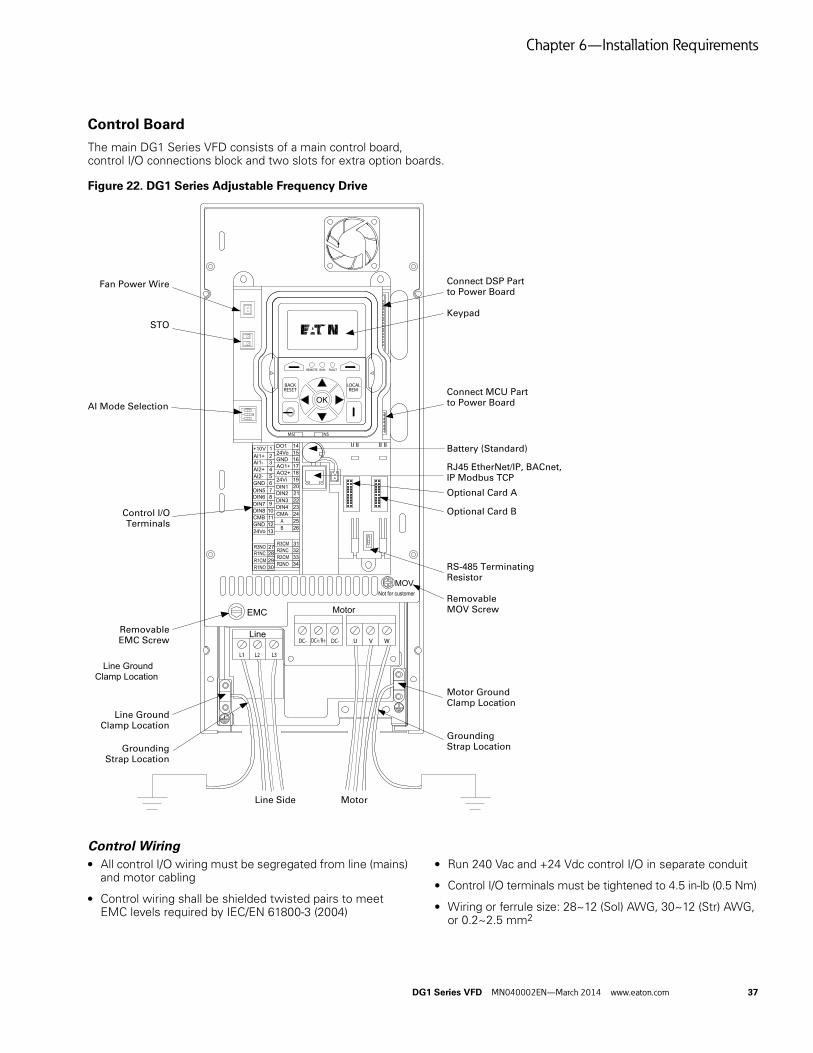
Chapter 6—Installation Requirements
DG1 Series VFD MN040002EN—March 2014 www.eaton.com 37
Control Board
The main DG1 Series VFD consists of a main control board, control I/O connections block and two slots for extra option boards.
Figure 22. DG1 Series Adjustable Frequency Drive
Control Wiring ● All control I/O wiring must be segregated from line (mains)
and motor cabling
● Control wiring shall be shielded twisted pairs to meet EMC levels required by IEC/EN 61800-3 (2004)
● Run 240 Vac and +24 Vdc control I/O in separate conduit
● Control I/O terminals must be tightened to 4.5 in-lb (0.5 Nm)
● Wiring or ferrule size: 28~12 (Sol) AWG, 30~12 (Str) AWG, or 0.2~2.5 mm2
Connect DSP Partto Power Board
Keypad
Connect MCU Partto Power Board
Battery (Standard)
RJ45 EtherNet/IP, BACnet,IP Modbus TCP
Optional Card A
Optional Card B
RS-485 TerminatingResistor
RemovableMOV Screw
Motor GroundClamp Location
GroundingStrap LocationGrounding
Strap Location
Line GroundClamp Location
RemovableEMC Screw
Control I/OTerminals
AI Mode Selection
STO
Fan Power Wire
Line Side Motor
Line Ground
Clamp Location
ON
12
3
ON
1

Chapter 6—Installation Requirements
38 DG1 Series VFD MN040002EN—March 2014 www.eaton.com
Safe Torque Off (STO)
The PowerXL DG1 includes Safe Torque Off (STO) functionality as standard and provides:
● Isolation from the control board will stop IGBT from firing
● Functional Safety SIL1 Certification: IEC/EN 61800-5-2 and DIN EN ISO 13849 Category 1, Level C
● Higher category levels achievable with safety relays
Figure 23. Thermistor STO Wiring Diagram
Connection to Power Section
Figure 24 shows the general connections for the frequency inverter in the power section.
Three-Phase Input Connection
Figure 24. Connection to Power Section
Terminal Designations in the Power Section ● L1, L2, L3: Connection terminals for the supply voltage
(input, input voltage)
● U, V, W: Connection terminals for the three-phase line to the AC motor (output, frequency inverter)
● PE: Connection for protective ground (reference potential). PES with mounted cable routing plate for shielded cables
Line Motor

Chapter 6—Installation Requirements
DG1 Series VFD MN040002EN—March 2014 www.eaton.com 39
Ground Connection
The ground connection is connected directly with the cable clamp plates.
The shielded cables between the frequency inverter and the motor should be as short as possible. Connect the shielding on both ends and over a large surface area with protective ground PES (Protective Earth Shielding). You can connect the shielding of the motor cable directly to the cable clamp plate (360 degrees coverage) with the protective ground.
The frequency inverter must always be connected to the ground potential via a grounding cable (PE).
Figure 25. Grounding
CAUTIONBefore connecting the AC drive to mains make sure that theEMC protection class settings of the drive are appropriatelymade.
Note: After having performed the change write “EMC level modified” on the sticker included in the DG1 delivery (see Figure 26) and note the date. Unless already done, attach the sticker close to the name plate of the AC drive.
Product Modified Sticker
Figure 26. Product Modified Sticker
Checking the Cable and Motor Insulation
1. Check the motor cable insulation as follows:
● Disconnect the motor cable from terminals U, V and W of the DG1 Series drive and from the motor
● Measure the insulation resistance of the motor cable between each phase conductor as well as between each phase conductor and the protective ground conductor
● The insulation resistance must be >1M ohm
2. Check the input power cable insulation as follows:
● Disconnect the input power cable from terminals L1/N, L2/N and L3 of the DG1 Series drive and from the utility line feeder
● Measure the insulation resistance of the input power cable between each phase conductor as well as between each phase conductor and the protective ground conductor
● The insulation resistance must be >1M ohm
3. Check the motor insulation as follows:
● Disconnect the motor cable from the motor and open any bridging connections in the motor connection box
● Measure the insulation resistance of each motor winding. The measurement voltage must equal at least the motor nominal voltage but not exceed 1000V
● The insulation resistance must be >1M ohm
15
25
(FR1–FR4)No. 2 Phillips
(FR5)No. 3 Phillips
(FR1–FR3)
PE
(FR4, FR5)
(FR1–FR3)M4, 10 in-lb (1.1 Nm)
(FR4)M4, 14 in-lb (1.6 Nm)
(FR5)M6, 35 in-lb (4.0 Nm)

Chapter 7—EMC Installation
40 DG1 Series VFD MN040002EN—March 2014 www.eaton.com
Chapter 7—EMC Installation
The responsibility to meet the local system EMC limit values and electromagnetic compatibility requirements is the responsibility of the end user or the system operator. This operator must also take measures to minimize or remove emissions in the environment concerned (see figure on Page 41). He must also use means to increase the interference immunity of the system devices.
In a drive system (PDS) with frequency inverters, you should take measures for electromagnetic compatibility (EMC) while doing your planning, because changes or improvements to the installation site, which are required in the installation or while mounting, are normally associated with additional higher costs.
The technology and system of a frequency inverter cause the flow of high frequency leakage current during operation. All grounding measures must therefore be implemented with low impedance connections over a large surface area.
With leakage currents greater than 3.5 mA, in accordance with VDE 0160 or EN 61800-5-1, either
● the protective conductor must have a cross-section of at least 10 mm2
● the protective conductor must be open-circuit monitored, and the supply must be automatically disconnected in case of discontinuity of the protective earthing conductor, or
● the second protective conductor must be fitted.
For an EMC-compliant installation, we recommend the following measures:
● Installation of the frequency inverter in a metallic, electrically conducting enclosure with a good connection to earth
● Shielded motor cables (short cable lengths)
● Ground all conductive components and housings in a drive system using as short a line as possible with the greatest possible cross-section (Cu-braid)
EMC Measures in the Control Panel
For EMC-compatible installation, connect all metallic parts of the device and the switching cabinet together over broad surfaces and so that high-frequencies will be conducted. Mounting plates and cabinet doors should make good contact and be connected with short HF-braided cables. Avoid using painted surfaces (anodized, chromized). An overview of all EMC measures is provided in the figure on Page 41.
Install the frequency inverter as directly as possible (without spacers) on a metal plate (mounting plate).
Route input and motor cables in the switch cabinet as close to the ground potential as possible. This is because free moving cables act as antennas.
When laying HF cables (for example, shielded motor cables) or suppressed cables (for example, input supply cables, control circuit and signal cables) in parallel, a minimum clearance of 11.81 in (300 mm) should be ensured in order to prevent the radiation of electromagnetic energy. Separate cable routing should also be ensured when large voltage potential differences are involved. Any necessary crossed cabling between the control signal and power cables should always be implemented at right angles (90 degrees).
Never lay control or signal cables in the same duct as power cables. Analog signal cables (measured, reference and correction values) must be shielded.
Earthing
The ground connection (PE) in the cabinet should be connected from the input supply to a central earth point (mounting plate). All protective conductors should be routed in star formation from this earth point and all conductive components of the PDS (frequency inverter, motor reactor, motor filter, main choke) are to be connected.
Avoid ground loops when installing multiple frequency inverters in one cabinet. Make sure that all metallic devices that are to be grounded have a broad area connection with the mounting plate.
Screen Earth Kit
Cables that are not shielded work like antennas (sending, receiving). Make sure that any cables that may carry disruptive signals (for example, motor cables) and sensitive cables (analog signal and measurement values) are shielded apart from one another with EMC-compatible connections.
The effectiveness of the cable shield depends on a good shield connection and a low shield impedance.
Use only shields with tinned or nickel-plated copper braiding. Braided steel shields are unsuitable.
Control and signal lines (analog, digital) should always be grounded on one end, in the immediate vicinity of the supply voltage source (PES).

Chapter 7—EMC Installation
DG1 Series VFD MN040002EN—March 2014 www.eaton.com 41
Installation Requirements
Figure 27. EMC-Compliant Setup—460/480 Vac
Notes1 Power cable: L1, L2, L3 and U, V, W. 2 Control and signal lines: 1 to 36, fieldbus connection Large-area connection of all metallic control panel components. Mounting surfaces of frequency inverter
and cable shielding must be free from paint. Connect the cable shielding in the output of the frequency inverter with a large surface area contact to the ground potential (PES). Large-area cable shield contacts with motor. Large-area earth connection of all metallic parts.
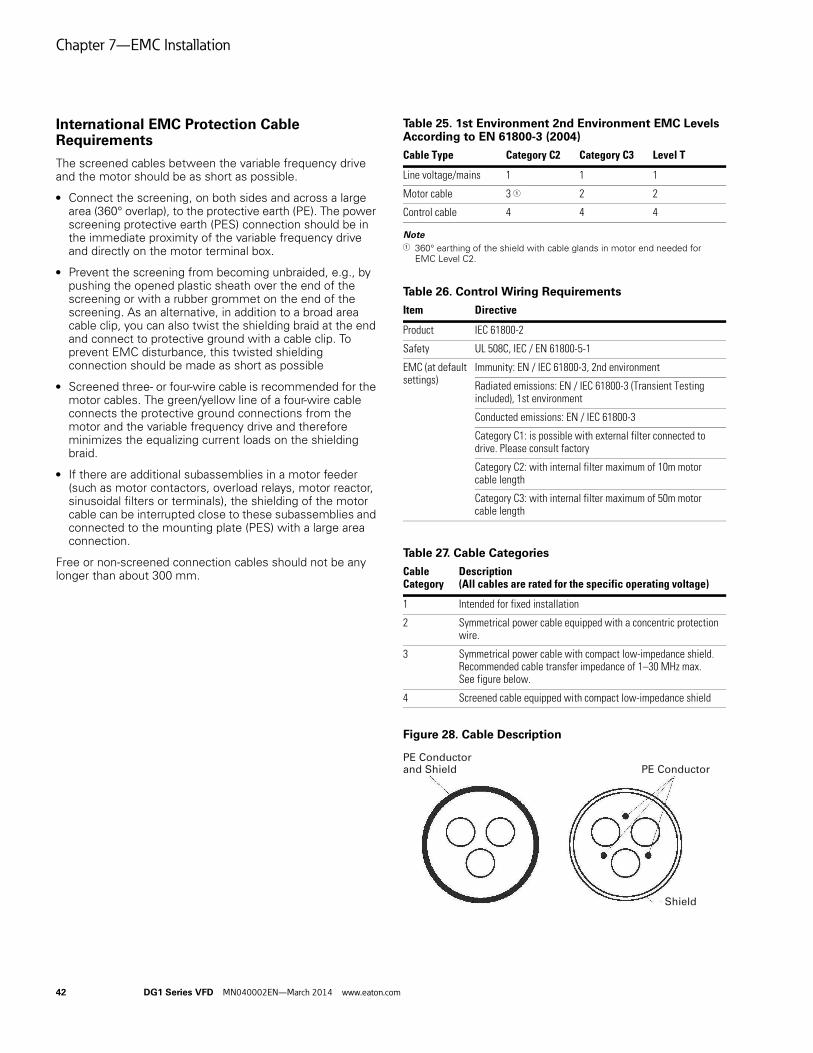
Chapter 7—EMC Installation
42 DG1 Series VFD MN040002EN—March 2014 www.eaton.com
International EMC Protection Cable Requirements
The screened cables between the variable frequency drive and the motor should be as short as possible.
● Connect the screening, on both sides and across a large area (360° overlap), to the protective earth (PE). The power screening protective earth (PES) connection should be in the immediate proximity of the variable frequency drive and directly on the motor terminal box.
● Prevent the screening from becoming unbraided, e.g., by pushing the opened plastic sheath over the end of the screening or with a rubber grommet on the end of the screening. As an alternative, in addition to a broad area cable clip, you can also twist the shielding braid at the end and connect to protective ground with a cable clip. To prevent EMC disturbance, this twisted shielding connection should be made as short as possible
● Screened three- or four-wire cable is recommended for the motor cables. The green/yellow line of a four-wire cable connects the protective ground connections from the motor and the variable frequency drive and therefore minimizes the equalizing current loads on the shielding braid.
● If there are additional subassemblies in a motor feeder (such as motor contactors, overload relays, motor reactor, sinusoidal filters or terminals), the shielding of the motor cable can be interrupted close to these subassemblies and connected to the mounting plate (PES) with a large area connection.
Free or non-screened connection cables should not be any longer than about 300 mm.
Table 25. 1st Environment 2nd Environment EMC Levels According to EN 61800-3 (2004)
Note1 360° earthing of the shield with cable glands in motor end needed for
EMC Level C2.
Table 26. Control Wiring Requirements
Table 27. Cable Categories
Figure 28. Cable Description
Cable Type Category C2 Category C3 Level T
Line voltage/mains 1 1 1
Motor cable 3 1 2 2
Control cable 4 4 4
Item Directive
Product IEC 61800-2
Safety UL 508C, IEC / EN 61800-5-1
EMC (at default settings)
Immunity: EN / IEC 61800-3, 2nd environment
Radiated emissions: EN / IEC 61800-3 (Transient Testing included), 1st environment
Conducted emissions: EN / IEC 61800-3
Category C1: is possible with external filter connected to drive. Please consult factory
Category C2: with internal filter maximum of 10m motor cable length
Category C3: with internal filter maximum of 50m motor cable length
Cable Category
Description(All cables are rated for the specific operating voltage)
1 Intended for fixed installation
2 Symmetrical power cable equipped with a concentric protection wire.
3 Symmetrical power cable with compact low-impedance shield. Recommended cable transfer impedance of 1–30 MHz max. See figure below.
4 Screened cable equipped with compact low-impedance shield
PE Conductorand Shield
Shield
PE Conductor

Chapter 7—EMC Installation
DG1 Series VFD MN040002EN—March 2014 www.eaton.com 43
Installation in Corner-Grounded Network
Corner grounding is allowed for all the drive types.
In these circumstances the EMC protection class must be changed to level C4 following the instructions below.
Installation in IT System
If your supply network is an IT (impedance-grounded) system but your AC drive is EMC-protected according to class C2 you need to modify the EMC protection of the AC drive to EMC level C4. This is done by removing the built-in EMC Screw with a simple procedure described below:
WARNINGDo not perform any modifications on the AC drive whenit is connected to mains.
WARNINGElectric shock hazard—risk of injuries! Carry out wiringwork only if the unit is de-energized.
After disconnecting the supply, wait at least five minutesbefore removing the cover to allow the intermediatecircuit capacitors to discharge.
WARNINGFailure to follow these instructions will result in death orserious injury.
Frame 1 to Frame 5
Remove the main cover of the AC drive (see Figure 30) and locate the screw jumper connecting the built-in RFI-filters to ground. Remove the screw jumper to disconnect the EMC protection. Once the screw is removed, it can be reconnected to re-engage the EMC protection.
Figure 29. Locations of the EMC Screw in Frame 1, Frame 2, Frame 3 and Frame 4
Figure 30. Locations of the EMC Screws in Frame 5

Appendix A—Technical Data and Specifications
44 DG1 Series VFD MN040002EN—March 2014 www.eaton.com
Appendix A—Technical Data and Specifications
Table 28. PowerXL Series—DG1
Attribute Description Specification
Input ratings Input voltage Uin 208V to 240V, 380V to 500V, 525V to 600V, –15 to 10%
Input frequency 50 Hz to 60 Hz (variation up to 45 Hz to 66 Hz)
Connection to power Once per minute or less
Starting delay 3 s (FR1 to FR2), 4 s (FR3), 5 s (FR4), 6 s (FR5)
Short-circuit withstand rating 100 kAIC
Output ratings Output voltage 0 to Uin
Continuous output current IL: ambient temperature maximum 40°C, up to 60°C with derating, overload 1.1 x IL (1 min./10 min.)
IH: ambient temperature maximum 50°C, up to 60°C with derating, overload 1.5 x IH (1 min./10 min.)
Overload current 150% respectively 110% (1 min./10 min.)
Initial output current 200% (2 s/20 s)
Output frequency 0–400 Hz (standard)
Frequency resolution 0.01 Hz
Control characteristics Control methods Frequency control
Speed control
Open-loop speed control
Open-loop torque control
Switching frequency Range: FR1–3: 1 kHz to 12 kHz FR4–5: 1 kHz to 10 kHzDefaults: FR1–3: 4 kHz (IH), 6 kHz (IL) FR4–5: 3.6 kHzAutomatic switching frequency derating in case of overload.
Frequency reference Analog input: resolution 0.1% (10-bit), accuracy +1%
Panel reference: resolution 0.01 Hz
Field weakening point 20 Hz to 400 Hz
Acceleration time 0.1 s to 3000 s
Deceleration time 0.1 s to 3000 s
Braking torque DC brake: 30% x Motor Rated Torque (Tn) (without brake chopper)
Dynamic braking (with optional brake chopper using an external brake resistor): 100% continuous maximum rating
Ambient conditions Ambient operating temperature –10°C (no frost) to +50°C, up to +60°C with derating (CT)
–10°C (no frost) to +40°C, up to +55°C with derating (VT)
Storage temperature –40°C to +70°C
Relative humidity 0–95% RH, noncondensing, non-corrosive
Air quality:● Chemical vapors● Mechanical particles
Tested according to IEC 60068-2-60 Test Key: Flowing mixed gas corrosion test, Method 1 (H2S [hydrogen sulfide] and SO2 [sulfur dioxide])Designed according to: IEC 60721-3-3, unit in operation, class 3C2 IEC 60721-3-3, unit in operation, class 3S2
Altitude 100% load capacity (no derating) up to 3280 ft (1000 m); 1% derating for each 328 ft (100 m) above 3280 ft (1000 m); max. 9842 ft (3000 m) (2000 m for corner grounded earth main systems)
Vibration:● EN 61800-5-1● EN 60668-2-6
5–150 Hz
Displacement amplitude: 1 mm (peak) at 5 Hz to 15.8 Hz (FR1–FR5)
Maximum acceleration amplitude: 1g at 15.8 Hz to 150 Hz (FR1–FR5)

Appendix A—Technical Data and Specifications
DG1 Series VFD MN040002EN—March 2014 www.eaton.com 45
Ambient conditions, continued
Shock:● ISTA 1 A● EN 60068-2-27
Storage and shipping: maximum 15 g, 11 ms (in package)
Overvoltage Overvoltage Category III
Pollution degree Pollution Degree 2
Enclosure class IP21/Type 1 standard in entire kW/hp rangeIP54/Type 12 optionNote: Keypad or keypad hole plug required to be mounted in drive for IP54/Type 12 rating
Immunity Fulfills EN 61800-3 (2004), first and second environment
MTBF FR1: 165,457 hours
FR2: 134,833 hours
FR3: 102,515 hours
FR4: 121,567 hours
FR5: 108,189 hours
FR6: Available in 2015
Standards Safety UL 508C, CSA C22.2 No. 274-13 and EN 61800-5-1
EMC +EMC2: EN 61800-3 (2004), Category C2The drive can be modified for IT networks and corner grounding TN system
Electrostatic discharge Second environment, IEC 61000-4-2, 4 kV CD or 8 kV AD, Criterion B
Fast transient burst Second environment, IEC 61000-4-4, 2 kV/5 kHz, Criterion B
Dielectrical strength Primary to secondary: 3600 Vac/5100 VdcPrimary to earth: 2000 Vac/2828 Vdc
Approvals EN 61800-5-1 (2007), CE, UL and cUL (see nameplate for more detailed approvals)
Fieldbus connections EtherNet/IP, Modbus® TCP, Modbus RTU, BACnet
Safety/protections Overvoltage protection Yes
Overvoltage trip limit 240V drives: 456V
480V drives: 911V
Undervoltage protection Yes
Undervoltage trip limit 240V drives: 211V
480V drives: 370V
Earth fault protection Yes
Input phase supervision Yes
Motor phase supervision Yes
Overcurrent protection Yes
Unit overtemperature protection Yes
Motor overload protection Yes
Motor stall protection Yes
Motor underload protection Yes
DC bus overvoltage control Yes
Short-circuit protection of 24V reference voltages
Yes
Surge protection Yes (differential mode 2 kV; common mode 4 kV)
Common coated boards Yes (prevents corrosion)
Table 28. PowerXL Series—DG1, continued
Attribute Description Specification

Appendix B—Installation Guidelines
46 DG1 Series VFD MN040002EN—March 2014 www.eaton.com
Appendix B—Installation Guidelines
Cable and Fuse Sizing
See Page 30 for cable stripping guidelines.
Table 29. North America Cable and Fuse Sizes—208 Vac to 240 Vac Ratings
Notes1 Line and motor cable size is selected according to UL508C Table 40.3 for copper conductor rated 75°C. Use only with copper wire rated 75°C here.
Size requirements for other different wire types are defined in the National Electrical Code, ANSI/NFPA 70.2 Earthing conductor size is determined by the maximum overcurrent device rating used ahead of the drive according to UL508C Table 6.4.3 If power cubes or bypass are used, a UL recognized Class T fuse is recommended.4 Available in 2015.
Frame Size
AmpSuffix
208V Input Current (CT/IH)
208V Input Current (VT/IL)
NEC Motor Amp Ratingat 230V
NECMotor Amp Ratingat 208V
Current(CT/IH) at 50°C
Current (VT/IL) at 40°C
FuseRating(Class T)
NEC Wire Size (AWG)
Terminal Connection Size (AWG)
Line andMotor Ground
Line andMotor Ground
FR1 3D7 3.2 4.4 4.2 4.6 3.7 4.8 10 14 14 24–10 18–10
4D8 4.4 6.1 6.0 6.6 4.8 6.6 10 14 14 24–10 18–10
6D6 6.1 7.2 6.8 7.5 6.6 7.8 10 14 14 24–10 18–10
7D8 7.2 10.2 9.6 10.6 7.8 11 15 14 14 24–10 18–10
011 10.2 11.6 — — 11 12.5 15 12 14 24–10 18–10
FR2 012 10.2 16.3 15.2 16.7 12.5 17.5 20 10 12 20–6 12–6
017 16.2 23.2 22 24.2 17.5 25 30 8 10 20–6 12–6
025 23.1 29 28 30.8 25 31 35 8 10 20–6 12–6
FR3 031 28.7 44.2 42 46.2 31 48 60 6 10 6–2 14–4
048 44.4 56 54 59.4 48 61 80 4 8 6–2 14–4
FR4 061 56.4 64.6 68 74.8 61 75 100 3 8 6–1/0 10–1/0
075 69.4 78 80 88 75 88 110 2 6 6–1/0 10–1/0
088 81.4 94.3 104 114 88 114 125 1/0 6 6–1/0 10–1/0
FR5 114 105.5 129 130 143 114 143 175 3/0 6 1/0–350 kcmil
8–250 kcmil
143 132.3 157 154 169 143 170 200 4/0 6 1/0–350 kcmil
8–250 kcmil
170 157.3 189 192 211 170 211 250 300 4 1/0–350 kcmil
8–250 kcmil
FR6 211 195.2 4 248 261 211 261 4 4 3 4 4
261 241.4 4 312 312 261 312 4 4 3 4 4

Appendix B—Installation Guidelines
DG1 Series VFD MN040002EN—March 2014 www.eaton.com 47
Table 30. International Cable and Fuse Sizes—208 Vac to 240 Vac Ratings
Notes1 Line and motor cable size is selected according to IEC60364–5–52:2009 Table B.52.4 for copper conductor with PVC insulation with a wiring condition of ambient
temperature 30°C in air and an installation method of “B2” (cables in conduit and cable trunking systems). For other wiring conditions, please refer to the standard of IEC60364–5–52:2009 for suitable cable sizes.
2 Earthing conductor size is determined by the cross–sectional area of phase conductors according to IEC/EN61800–5–1:2007 Table 5. So if phase conductor size is changed, earthing conductor size should also be changed accordingly.
3 If power cubes or bypass are used, a Class gG/gL fuse is recommended.4 Available in 2015.
Frame Size
AmpSuffix
208V Input Current (CT/IH)
208V Input Current(VT/IL)
Current(CT/IH) at 50°C
Current (VT/IL) at 40°C
FuseRating(gG/gL)
Mains and Motor Cable Cu (mm2)
Terminal Cable Size
Main Terminal Cu (mm2)
Earth Terminal Cu (mm2)
FR1 3D7 3.2 4.4 3.7 4.8 6 3*1.5+1.5 0.2–6 solid or 0.2–4 stranded
0.75–6
4D8 4.4 6.1 4.8 6.6 10 3*1.5+1.5 0.2–6 solid or 0.2–4 stranded
0.75–6
6D6 6.1 7.2 6.6 7.8 16 3*1.5+1.5 0.2–6 solid or 0.2–4 stranded
0.75–6
7D8 7.2 10.2 7.8 11 16 3*1.5+1.5 0.2–6 solid or 0.2–4 stranded
0.75–6
011 10.2 11.6 11 12.5 16 3*1.5+1.5 0.2–6 solid or 0.2–4 stranded
0.75–6
FR2 012 10.2 16.3 12.5 17.5 20 3*4+4 0.5–16 4–16
017 16.2 23.2 17.5 25 32 3*4+4 0.5–16 4–16
025 23.1 29 25 31 32 3*6+6 0.5–16 4–16
FR3 031 28.7 44.2 31 48 50 3*16+16 16–35 2.5–25
048 44.4 56 48 61 63 3*16+16 16–35 2.5–25
FR4 061 56.4 64.6 61 75 80 3*25+16 16–50 6–50
075 69.4 78 75 88 100 3*35+16 16–50 6–50
088 81.4 94.3 88 114 125 3*50+25 16–50 6–50
FR5 114 105.5 129 114 143 160 3*70+35 50–185 10–120
143 132.3 157 143 170 200 3*95+50 50–185 10–120
170 157.3 189 170 211 250 3*150+95 50–185 10–120
FR6 211 195.2 4 211 261 4 4 4 4
261 241.4 4 261 312 4 4 4 4

Appendix B—Installation Guidelines
48 DG1 Series VFD MN040002EN—March 2014 www.eaton.com
Table 31. North America Cable and Fuse Sizes—440 Vac to 500 Vac Ratings
Notes1 Line and motor cable size is selected according to UL508C Table 40.3 for copper conductor rated 75°C. Use only with copper wire rated 75°C here.
Size requirements for other different wire types are defined in the National Electrical Code, ANSI/NFPA 70.2 Earthing conductor size is determined by the maximum overcurrent device rating used ahead of the drive according to UL508C Table 6.4.3 If power cubes or bypass are used, a UL recognized Class T fuse is recommended.4 Available in 2015.
Frame Size
AmpSuffix
400V Input Current (CT/IH)
400V Input Current (VT/IL)
NEC MotorAmp Ratingat 460V
Current(CT/IH) at 50°C
Current (VT/IL) at 40°C
FuseRating(Class T)
NEC Wire Size (AWG)
Terminal Connection Size (AWG)
Line andMotor Ground
Line andMotor Ground
FR1 2D2 2.0 3.1 3.0 2.1 3.0 10 14 14 30–10 18–10
3D3 3.1 4 3.4 3.0 3.4 10 14 14 30–10 18–10
4D3 4.0 5.2 4.8 3.4 4.8 10 14 14 30–10 18–10
5D6 5.2 7.1 7.6 4.8 7.6 10 14 14 30–10 18–10
7D6 7.1 8.4 — 7.6 9 15 14 14 30–10 18–10
9D0 8.4 11.2 11 9 12 15 14 14 30-10 18–10
FR2 012 11.2 15 14 11 14 20 12 12 20–6 12–6
016 14.9 21.5 21 14 21 30 10 10 20–6 12–6
023 21.4 29 27 21 27 35 8 10 20–6 12–6
FR3 031 28.8 35.2 34 27 34 50 8 10 6–2 14–4
038 35.3 42.6 40 34 40 60 6 10 6–2 14–4
046 42.8 55.7 52 40 52 80 4 8 6–2 14–4
FR4 061 56.7 65.7 65 52 65 100 4 8 6–1/0 10–1/0
072 66.9 79.4 77 65 77 110 3 6 6–1/0 10–1/0
087 80.9 97 96 77 96 125 1 6 6–1/0 10–1/0
FR5 105 97.6 129 124 96 124 175 3/0 6 1/0–350 kcmil 8–250 kcmil
140 130.1 157 156 124 156 200 3/0 6 1/0–350 kcmil 8–250 kcmil
170 158.0 189 180 156 180 250 250 kcmil 4 1/0–350 kcmil 8–250 kcmil
FR6 205 190.6 4 240 180 240 350 4 3 4 4
261 4 4 302 240 302 400 4 3 4 4

Appendix B—Installation Guidelines
DG1 Series VFD MN040002EN—March 2014 www.eaton.com 49
Table 32. International Cable and Fuse Sizes—380 Vac to 440 Vac Ratings
Notes1 Line and motor cable size is selected according to IEC60364–5–52:2009 Table B.52.4 for copper conductor with PVC insulation with a wiring condition of ambient
temperature 30°C in air and an installation method of “B2” (cables in conduit and cable trunking systems). For other wiring conditions, please refer to the standard of IEC60364–5–52:2009 for suitable cable sizes.
2 Earthing conductor size is determined by the cross–sectional area of phase conductors according to IEC/EN61800–5–1:2007 Table 5. So if phase conductor size is changed, earthing conductor size should also be changed accordingly.
3 If power cubes or bypass are used, a Class gG/gL fuse is recommended.4 Available in 2015.
Frame Size
AmpSuffix
400V Input Current(CT/IH)
400V Input Current(VT/IL)
Current(CT/IH) at 50°C
Current (VT/IL) at 40°C
FuseRating(gG/gL)
Mains and MotorCable Cu (mm2)
Terminal Cable Size
Main Terminal Cu (mm2)
Earth Terminal Cu (mm2)
FR1 2D2 2.0 3.1 2.2 3.3 6 3*1.5+1.5 0.2–6 solid or 0.2–4 stranded
0.75–6
3D3 3.1 4 3.3 4.3 6 3*1.5+1.5 0.75–6
4D3 4.0 5.2 4.3 5.6 10 3*1.5+1.5 0.75–6
5D6 5.2 7.1 5.6 7.6 16 3*1.5+1.5 0.75–6
7D6 7.1 8.4 7.6 9 16 3*1.5+1.5 0.75–6
9D0 8.4 11.2 9 12 16 3*1.5+1.5 0.75–6
FR2 012 11.2 15 12 16 20 3*4+4 0.5–16 4–16
016 14.9 21.5 16 23 25 3*4+4 0.5–16 4–16
023 21.4 29 23 31 32 3*6+6 0.5–16 4–16
FR3 031 28.8 35.2 31 38 40 3*16+16 16–35 2.5–25
038 35.3 42.6 38 46 50 3*16+16 16–35 2.5–25
046 42.8 55.7 46 61 63 3*16+16 16–35 2.5–25
FR4 061 56.7 65.7 61 72 80 3*25+16 16–50 6–50
072 66.9 79.4 72 87 100 3*35+16 16–50 6–50
087 80.9 97 87 105 125 3*50+25 16–50 6–50
FR5 105 97.6 129 105 140 160 3*70+35 50–185 10–120
140 130.1 157 140 170 200 3*95+50 50–185 10–120
170 158.0 189 170 205 250 3*120+70 50–185 10–120
FR6 205 190.6 4 205 261 315 3*240+120 4 4
261 4 4 261 310 350 2*(3*95+50) 4 4

Appendix B—Installation Guidelines
50 DG1 Series VFD MN040002EN—March 2014 www.eaton.com
Temperature Deratings
Table 33. 230V Temperature and Switching Frequency Deratings (VT)
Note1 FR6 available in 2015.
Variable Torque (VT) /Low Overload (IL)
Frame Size
Percentage of Rated CurrentSwitching Frequency
Temperature 1 kHz 2 kHz 3 kHz 3.6 kHz 4 kHz 5 kHz 6 kHz 7 kHz 8 kHz 9 kHz 10 kHz 12 kHz
40°C FR1 100.0% 100.0% 100.0% 100.0% 100.0% 100.0% 100.0% 96.8% 93.6% 90.4% 85.6% 80.8%
FR2 100.0% 100.0% 100.0% 100.0% 100.0% 100.0% 100.0% 97.3% 94.6% 91.9% 87.9% 83.9%
FR3 100.0% 100.0% 100.0% 100.0% 100.0% 100.0% 100.0% 100.0% 100.0% 100.0% 100.0% 100.0%
FR4 100.0% 100.0% 100.0% 100.0% 97.8% 95.6% 93.4% 91.2% 87.4% 83.6% 79.8% —
FR5 100.0% 100.0% 100.0% 100.0% 95.5% 91.0% 86.5% 82.0% 78.4% 74.7% 71.1% —
FR6 1 1 1 1 1 1 1 1 1 1 1 —
50°C FR1 84.0% 84.0% 84.0% 84.0% 84.0% 84.0% 84.0% 80.8% 77.6% 74.4% 69.6% 64.8%
FR2 87.1% 87.1% 87.1% 87.1% 87.1% 87.1% 87.1% 84.4% 81.7% 79.0% 75.0% 71.0%
FR3 93.4% 93.4% 93.4% 93.4% 93.4% 93.4% 93.4% 93.4% 93.4% 93.4% 90.2% 86.9%
FR4 87.7% 87.7% 87.7% 87.7% 85.5% 83.3% 81.1% 78.9% 76.0% 73.1% 70.2% —
FR5 80.6% 80.6% 80.6% 80.6% 76.7% 72.7% 68.8% 64.9% 60.0% 55.1% 50.2% —
FR6 1 1 1 1 1 1 1 1 1 1 1 —
60°C FR1 68.0% 68.0% 68.0% 68.0% 68.0% 68.0% 68.0% 65.9% 63.7% 61.6% 58.4% 55.2%
FR2 74.2% 74.2% 74.2% 74.2% 74.2% 74.2% 74.2% 71.0% 67.7% 64.5% 59.7% 54.8%
FR3 82.0% 82.0% 82.0% 82.0% 82.0% 82.0% 82.0% 80.3% 78.7% 77.0% 73.8% 70.5%
FR4 74.6% 74.6% 74.6% 74.6% 72.1% 69.7% 67.3% 64.9% 62.3% 59.6% 57.0% —
FR5 64.0% 64.0% 64.0% 64.0% 60.9% 57.8% 54.7% 51.7% 47.9% 44.2% 40.5% —
FR6 1 1 1 1 1 1 1 1 1 1 1 —

Appendix B—Installation Guidelines
DG1 Series VFD MN040002EN—March 2014 www.eaton.com 51
Table 34. 230V Temperature and Switching Frequency Deratings (CT)
Note1 FR6 available in 2015.
Constant Torque (CT) /High Overload (IH)
Frame Size
Percentage of Rated CurrentSwitching Frequency
Temperature 1 kHz 2 kHz 3 kHz 3.6 kHz 4 kHz 5 kHz 6 kHz 7 kHz 8 kHz 9 kHz 10 kHz 12 kHz
40°C FR1 100.0% 100.0% 100.0% 100.0% 100.0% 100.0% 100.0% 100.0% 100.0% 100.0% 95.9% 91.8%
FR2 100.0% 100.0% 100.0% 100.0% 100.0% 100.0% 100.0% 100.0% 100.0% 100.0% 100.0% 100.0%
FR3 100.0% 100.0% 100.0% 100.0% 100.0% 100.0% 100.0% 100.0% 100.0% 100.0% 100.0% 100.0%
FR4 100.0% 100.0% 100.0% 100.0% 100.0% 100.0% 100.0% 100.0% 96.2% 92.3% 88.5% —
FR5 100.0% 100.0% 100.0% 100.0% 100.0% 100.0% 100.0% 100.0% 96.1% 92.2% 88.2% —
FR6 1 1 1 1 1 1 1 1 1 1 1 —
50°C FR1 100.0% 100.0% 100.0% 100.0% 100.0% 97.7% 95.5% 91.8% 88.2% 84.5% 79.1% 73.6%
FR2 100.0% 100.0% 100.0% 100.0% 100.0% 100.0% 100.0% 98.0% 96.0% 94.0% 91.0% 88.0%
FR3 100.0% 100.0% 100.0% 100.0% 100.0% 100.0% 100.0% 100.0% 100.0% 100.0% 100.0% 100.0%
FR4 100.0% 100.0% 100.0% 100.0% 97.1% 94.3% 91.4% 88.5% 84.7% 80.8% 77.0% —
FR5 100.0% 100.0% 100.0% 100.0% 95.1% 90.3% 85.4% 80.6% 74.5% 68.4% 62.4% —
FR6 1 1 1 1 1 1 1 1 1 1 1 —
60°C FR1 83.6% 83.6% 83.6% 83.6% 83.6% 80.9% 78.2% 75.5% 72.7% 70.0% 65.9% 61.8%
FR2 92.0% 92.0% 92.0% 92.0% 92.0% 92.0% 92.0% 130.0% 168.0% 80.0% 101.3% 68.0%
FR3 91.7% 91.7% 91.7% 91.7% 91.7% 90.6% 89.6% 88.5% 87.5% 86.1% 84.7% 83.3%
FR4 83.9% 83.9% 83.9% 83.9% 80.7% 77.6% 74.4% 71.3% 67.4% 63.6% 59.8% —
FR5 79.4% 79.4% 79.4% 79.4% 75.6% 71.8% 67.9% 64.1% 59.5% 54.9% 50.3% —
FR6 1 1 1 1 1 1 1 1 1 1 1 —

Appendix B—Installation Guidelines
52 DG1 Series VFD MN040002EN—March 2014 www.eaton.com
Table 35. 460V Temperature and Switching Frequency Deratings (VT)
Note1 FR6 available in 2015.
Variable Torque (VT) /Low Overload (IL)
Frame Size
Percentage of Rated CurrentSwitching Frequency
Temperature 1 kHz 2 kHz 3 kHz 3.6 kHz 4 kHz 5 kHz 6 kHz 7 kHz 8 kHz 9 kHz 10 kHz 12 kHz
40°C FR1 100.0% 100.0% 100.0% 100.0% 100.0% 100.0% 100.0% 93.8% 87.5% 81.3% 75.0% 62.5%
FR2 100.0% 100.0% 100.0% 100.0% 100.0% 100.0% 100.0% 95.2% 90.3% 85.5% 80.6% 71.0%
FR3 100.0% 100.0% 100.0% 100.0% 100.0% 100.0% 100.0% 95.5% 91.0% 86.5% 82.0% 73.0%
FR4 100.0% 100.0% 100.0% 100.0% 95.7% 91.4% 87.1% 81.8% 76.4% 71.1% 65.7% —
FR5 100.0% 100.0% 100.0% 100.0% 94.8% 89.6% 84.4% 77.8% 71.2% 64.6% 58.0% —
FR6 1 1 1 1 1 1 1 1 1 1 1 —
50°C FR1 75.0% 75.0% 75.0% 75.0% 75.0% 75.0% 75.0% 70.8% 66.7% 62.5% 58.3% 50.0%
FR2 80.6% 80.6% 80.6% 80.6% 80.6% 80.6% 80.6% 77.4% 74.2% 71.0% 67.7% 61.3%
FR3 84.9% 84.9% 84.9% 84.9% 84.9% 84.9% 84.9% 81.1% 77.2% 73.4% 69.5% 61.8%
FR4 87.6% 87.6% 87.6% 87.6% 83.7% 79.8% 75.8% 70.9% 66.0% 61.1% 56.2% —
FR5 82.9% 82.9% 82.9% 82.9% 78.0% 73.2% 68.3% 62.2% 56.1% 50.0% 43.9% —
FR6 1 1 1 1 1 1 1 1 1 1 1 —
60°C FR1 58.3% 58.3% 58.3% 58.3% 58.3% 58.3% 58.3% 54.2% 50.0% 45.8% 41.7% 33.3%
FR2 67.7% 67.7% 67.7% 67.7% 67.7% 67.7% 67.7% 64.5% 61.3% 58.1% 54.8% 48.4%
FR3 71.3% 71.3% 71.3% 71.3% 71.3% 71.3% 71.3% 67.5% 63.8% 60.0% 56.2% 48.7%
FR4 72.4% 72.4% 72.4% 72.4% 68.8% 65.2% 61.7% 57.2% 52.7% 48.3% 43.8% —
FR5 68.3% 68.3% 68.3% 68.3% 64.0% 59.8% 55.5% 50.2% 44.8% 39.5% 34.1% —
FR6 1 1 1 1 1 1 1 1 1 1 1 —

Appendix B—Installation Guidelines
DG1 Series VFD MN040002EN—March 2014 www.eaton.com 53
Table 36. 460V Temperature and Switching Frequency Deratings (CT)
Note1 FR6 available in 2015.
Constant Torque (CT) /High Overload (IH)
Frame Size
Percentage of Rated CurrentSwitching Frequency
Temperature 1 kHz 2 kHz 3 kHz 3.6 kHz 4 kHz 5 kHz 6 kHz 7 kHz 8 kHz 9 kHz 10 kHz 12 kHz
40°C FR1 100.0% 100.0% 100.0% 100.0% 100.0% 100.0% 100.0% 96.1% 92.1% 88.2% 82.2% 76.3%
FR2 100.0% 100.0% 100.0% 100.0% 100.0% 100.0% 100.0% 100.0% 100.0% 100.0% 93.5% 87.0%
FR3 100.0% 100.0% 100.0% 100.0% 100.0% 100.0% 100.0% 100.0% 100.0% 95.7% 89.1% 82.6%
FR4 100.0% 100.0% 100.0% 100.0% 100.0% 100.0% 100.0% 94.8% 89.7% 84.5% 79.3% —
FR5 100.0% 100.0% 100.0% 100.0% 94.1% 88.2% 82.4% 75.0% 67.6% 60.3% 52.9% —
FR6 1 1 1 1 1 1 1 1 1 1 1 —
50°C FR1 100.0% 100.0% 100.0% 100.0% 100.0% 95.7% 91.4% 87.1% 82.9% 78.6% 72.2% 65.8%
FR2 100.0% 100.0% 100.0% 100.0% 100.0% 95.7% 91.3% 87.0% 82.6% 78.3% 71.7% 65.2%
FR3 100.0% 100.0% 100.0% 100.0% 100.0% 94.6% 89.1% 83.7% 78.3% 72.8% 64.7% 56.5%
FR4 100.0% 100.0% 100.0% 100.0% 96.0% 92.0% 87.9% 82.9% 77.9% 72.8% 67.8% —
FR5 100.0% 100.0% 100.0% 100.0% 94.1% 88.2% 82.4% 75.0% 67.6% 60.3% 52.9% —
FR6 1 1 1 1 1 1 1 1 1 1 1 —
60°C FR1 92.1% 92.1% 92.1% 92.1% 92.1% 87.2% 82.2% 77.3% 72.3% 67.4% 60.0% 52.6%
FR2 78.3% 78.3% 78.3% 78.3% 78.3% 73.9% 69.6% 65.2% 60.9% 56.5% 50.0% 43.5%
FR3 80.4% 80.4% 80.4% 80.4% 80.4% 76.1% 71.7% 67.4% 63.0% 58.7% 52.2% 45.7%
FR4 87.4% 87.4% 87.4% 87.4% 83.0% 78.7% 74.4% 69.0% 63.6% 58.3% 52.9% —
FR5 82.4% 82.4% 82.4% 82.4% 77.2% 72.1% 66.9% 60.5% 54.0% 47.6% 41.2% —
FR6 1 1 1 1 1 1 1 1 1 1 1 —

Appendix B—Installation Guidelines
54 DG1 Series VFD MN040002EN—March 2014 www.eaton.com
Heat Loss Data
Table 37. Heat Loss Data
Brake Resistor Sizing
Table 38. Brake Resistor Sizing Data
Note1 FR6 and 575V available in 2015.
Frame Size
230V, 60 Hz 400V, 50 Hz 460V, 60 Hz 575V, 60 Hz
Amp SuffixVT/IL (110%)Pv (W)
CT/IH (150%)Pv (W)
VT/IL (110%)Pv (W)
CT/IH (150%)Pv (W)
VT/IL (110%)Pv (W)
CT/IH (150%)Pv (W)
VT/IL (110%)Pv (W)
CT/IH (150%)Pv (W)
FR1 2D2
3D3
4D3
5D6
7D6
9D0 180 98 136 88
FR2 012
016
023 390 330 360 292
FR3 031
038
046 700 494 603 472
FR4 061
072
087 1083 870 1080 875
FR5 105
140
170 1906 1479 1755 1429
FR6 205
261
230V 460V 575V
Frame Size
Brake ChopperNominal Currentat 80°C (A)
Minimum Resistance(Ohm)
Brake ChopperNominal Currentat 80°C (A)
Minimum Resistance(Ohm)
Brake ChopperNominal Currentat 80°C (A)
Minimum Resistance(Ohm)
FR1 30.0 15.3 25.0 36.4 1 1
FR2 53.0 8.7 52.0 17.5 1 1
FR3 70.0 6.6 70.0 13.0 1 1
FR4 200.0 2.3 400.0 2.3 1 1
FR5 200.0 2.3 400.0 2.3 1 1
FR6 1 1 1 1 1 1

Appendix C—Dimension Drawings
DG1 Series VFD MN040002EN—March 2014 www.eaton.com 55
Appendix C—Dimension Drawings
Approximate Dimensions in Inches (mm)
Figure 31. FR1 Dimension Drawing
0.53 (13.5)
REMOTERUNFAULT
STOP
BACKRESET
LOCALREMOTE
OKSTART
C 3.94 (100.0)
5.04(128.0)
D 1.97 (50.0)
A/B 0.79 (20.0)
A = Air gap around driveB = Space between two drives or drive and cabinetC = Free space above driveD = Free space below drive
Minimum Dimensions
For Class IP54, dimension A and B = 0
0.41 (10.5) 6.02 (153.0)
1.38 (35.0)1.20 (30.5)
1.73(44.0)
Ø 0.89(22.5)
1.73(44.0)
1.28 (32.5) 1.28 (32.5)
3.95(100.3)
2.24(57.0)
4.80(122.0)
7.89 (200.4)
3.94(100.0)
12.28(312.0)
0.28 (7.0)
Ø 0.28 (7.0)
Ø 0.28 (7.0)
Ø 0.47 (12.0)
3.94(100.0)
3.94(100.0)
12.87(327.0)
3.83(97.2)
7.03(178.5)
11.50(292.0)
Type 1/12 ULIP21/IP54 Metric
2-Ø 25.3
29.029.0
3-Ø 22.5
44.0
32.5 32.5
100.3
57.0

Appendix C—Dimension Drawings
56 DG1 Series VFD MN040002EN—March 2014 www.eaton.com
Approximate Dimensions in Inches (mm)
Figure 32. FR1 Dimension Drawing Flange Mount
REMOTERUNFAULT
STOP
BACKRESET
LOCALREMOTE
OKSTART
C 3.94 (100.0)
D 1.97 (50.0)
A/B 0.79 (20.0)
A = Air gap around driveB = Space between two drives or drive and cabinetC = Free space above driveD = Free space below drive
Minimum Dimensions
For Class IP54, dimension A and B = 0
4.80(122.0)
0.28 (7.0)
Ø 0.28 (7.0)3.94(100.0) Ø 0.47 (12.0)
12.64(321.0)
Ø 0.26 (6.5)
7.01 (178.0)
0.26 (6.5)
6.31 (160.4)3.94 (100.0)
2.84 (72.2)
1.40(35.5)
10.63(270.0)
3.83(97.2)
13.94(354.0)
6.31 (160.4)
10.63(270.0)
1.40 (35.0)1.20 (30.5)
1.70(44.0)
Ø 0.89(22.5)
1.40 (35.5)
1.70(44.0)
1.30 (32.5) 1.30 (32.5)
2.20(57.0)
3.90(100.3)
0.85 (21.5)
11.50(292.0)
7.89(200.4)
0.78(19.9)
1.10(28.0)
0.53 (13.5)
2.60 (66.0)
5.31(134.9)
Type 1/12 ULIP21/IP54 Metric
6-Ø 22.5
35.0
57.0
100.3
44.0
44.0
35.0
32.5 32.5

Appendix C—Dimension Drawings
DG1 Series VFD MN040002EN—March 2014 www.eaton.com 57
Approximate Dimensions in Inches (mm)
Figure 33. FR2 Dimension Drawing
14.96(380.0)
DANGER5 MIN
REMOTE
RUN
FAULT
STOP
BACK RESET
LOCAL REMOTE
OK START
MS
NS
DANGER5 MIN
REMOTE
RUN
FAULT
STOP
BACK RESET
LOCAL REMOTE
OK START
MS
NS
A = Air gap around driveB = Space between two drives or drive and cabinetC = Free space above driveD = Free space below drive
Minimum Dimensions
For Class IP54, dimension A and B = 0
C 6.30 (160.0)
1.77(44.9)
Ø 1.11(28.3)
5.80(147.2)
A/B 1.18 (30.0)
1.54 (39.0)
2.36 (60.0)
2.00(51.9)
1.30 (32.0)
1.54 (39.0)
A/B1.18
(30.0)
1.91 (48.5)
Ø0.89 (22.5)
1.30 (32.0)
0.45 (11.4)0.55 (14.0)
9.63 (244.7) 3.54 (90.0)
0.22 (5.5)Ø0.28 (7.0)
15.98(406.0)
16.50(419.0)
3.83(97.2)
9.22(234.2)
6.61(167.8)
5.63 (143.0)
5.28 (134.0)
3.54 (90.0)
3.54(90.0)
3.54(90.0)
Ø0.28(7.0)
Ø0.51(13.0)
Type 1/12 ULIP21/IP54 Metric
30.0
3-Ø 28.3
44.9 39.0
147.2
48.5
2-Ø 25.3
30.0
39.0

Appendix C—Dimension Drawings
58 DG1 Series VFD MN040002EN—March 2014 www.eaton.com
Approximate Dimensions in Inches (mm)
Figure 34. FR2 Dimension Drawing Flange Mount
1.77 (44.9)
Ø1.11(Ø28.3)
5.79(147.2)
1.54 (39.0)
2.04(51.9)
1.26 (32.0)
1.54 (39.0)
1.91(48.5)
Ø0.89(Ø22.5)
1.26 (32.0)
5.28 (134.0)
DANGER5 MIN
REMOTE RUN FAULT
STOP
BACKRESET
LOCALREMOTE
OKSTART
MS NS
DANGER5 MIN
REMOTE
RUN
FAULT
STOP
BACK RESET
LOCAL REMOTE
OK START
MS
NS
A = Air gap around driveB = Space between two drives or drive and cabinetC = Free space above driveD = Free space below drive
Minimum Dimensions
For Class IP54, dimension A and B = 0
C 6.30 (160.0)
A/B 1.18 (30.0)
2.36 (60.0)
A/B1.18
(30.0)
0.22 (5.5) Ø0.28 (7.0)
15.98(406.0)
3.54(90.0)
3.54(90.0)
Ø0.28(7.0)
Ø0.51(13.0)
14.96(380.0)
9.63 (244.7)0.98 (25.0)
1.07(27.1)
1.28(32.4)
0.55 (14.0)4.54
(115.2)5.10
(129.5)
7.64 (194.0)
6.57 (167.0)4.72 (120.0)10-Ø0.26
(Ø6.5)
1.38(35.0)
0.41 (10.3)4.72
(120.0)
7.09(180.0)
7.09(180.0)
3.83(97.2)
17.74(450.5)
9.93(252.2)
1.38 (35.0)
Type 1/12 UL

Appendix C—Dimension Drawings
DG1 Series VFD MN040002EN—March 2014 www.eaton.com 59
Approximate Dimensions in Inches (mm)
Figure 35. FR3 Dimension Drawing
21.97(558.0)
7.24 (184.0)
7.48 (190.0)
REMOTE
RUN
FAULT
STOP
BACK RESET
LOCAL REMOTE
OK START
MS
NS
DANGER5 MIN
REMOTE
RUN
FAULT
STOP
BACK RESET
LOCAL REMOTE
OK START
MS
NS
DANGER5 MIN
A = Air gap around driveB = Space between two drives or drive and cabinetC = Free space above driveD = Free space below drive
Minimum Dimensions
For Class IP54, dimension A and B = 0
C 7.87(200.0)
D 3.15 (80.0)
A/B1.97
(50.0)
13.49(342.6)
3.83(97.2)
21.46(545.0)
4.92(125.0)10.44 (265.1)
0.45 (11.3)0.59 (15.0)
20.41(518.5)
8.06 (204.6)
4.92(125.0)
2.77 (70.3)
1.26 (32.0)
3-Ø0.89(Ø22.5)
1.93(49.0)
6.23(158.3)
2.03 (51.5)1.92 (48.8)
2.19 (55.5)
0.18 (4.5)
4.92(125.0)
0.35(Ø9.0)
3-Ø0.14(Ø35.0)
A/B1.97
(50.0)
0.71(Ø18.0)
4.92(125.0)
0.35(Ø9.0)
1.26 (32.0)
Type 1/12 ULIP21/IP54 Metric
48.8
63.3
39.0
49.0
158.3
51.5
3-Ø35.0
39.0 3-Ø25.3
55.5
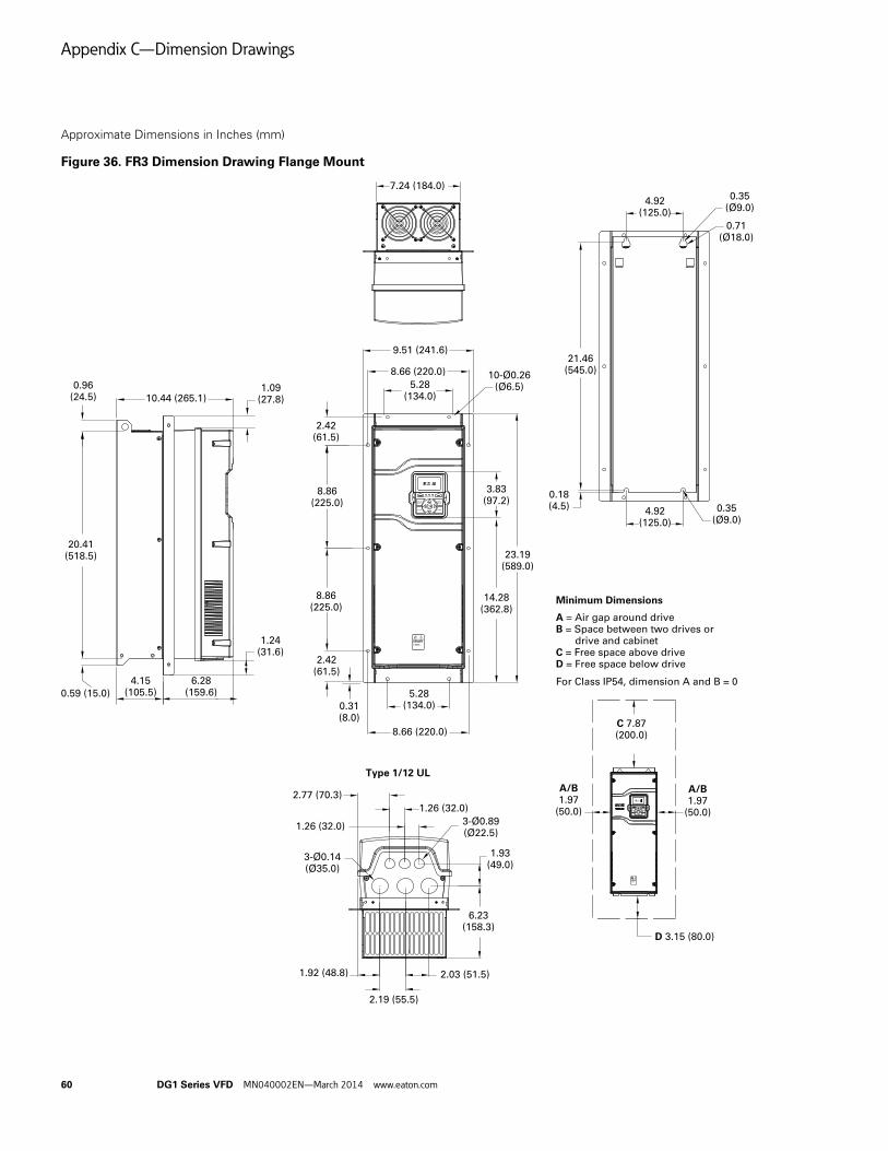
Appendix C—Dimension Drawings
60 DG1 Series VFD MN040002EN—March 2014 www.eaton.com
Approximate Dimensions in Inches (mm)
Figure 36. FR3 Dimension Drawing Flange Mount
DANGER5 MIN
REMOTE RUN FAULT
STOP
BACKRESET
LOCALREMOTE
OKSTART
MS NS
REMOTERUNFAULT
STOP
BACKRESET
LOCALREMOTE
OKSTART
MS NS
DANGER5 MIN
A = Air gap around driveB = Space between two drives or drive and cabinetC = Free space above driveD = Free space below drive
Minimum Dimensions
For Class IP54, dimension A and B = 0
C 7.87(200.0)
D 3.15 (80.0)
A/B1.97
(50.0)
9.51 (241.6)
8.66 (220.0)5.28
(134.0)1.09
(27.8)10.44 (265.1)0.96
(24.5)
4.15(105.5)
6.28(159.6)
2.42(61.5)
8.86(225.0)
3.83(97.2)
23.19(589.0)
14.28(362.8)
21.46(545.0)
2.77 (70.3)1.26 (32.0)
3-Ø0.89(Ø22.5)
1.93(49.0)
6.23(158.3)
2.03 (51.5)1.92 (48.8)
2.19 (55.5)
0.18(4.5)
4.92(125.0)
0.35(Ø9.0)
3-Ø0.14(Ø35.0)
0.71(Ø18.0)
4.92(125.0)
0.35(Ø9.0)
1.26 (32.0)
7.24 (184.0)
0.59 (15.0)
20.41(518.5)
A/B1.97
(50.0)
10-Ø0.26(Ø6.5)
0.31(8.0)
2.42(61.5)
8.86(225.0)
8.66 (220.0)
5.28(134.0)
1.24(31.6)
Type 1/12 UL

Appendix C—Dimension Drawings
DG1 Series VFD MN040002EN—March 2014 www.eaton.com 61
Approximate Dimensions in Inches (mm)
Figure 37. FR4 Dimension Drawing
23.26(590.7)
0.59 (15.0)
REMOTE
RUN
FAULT
STOP
BACK RESET
LOCAL REMOTE
OK START
MS
NS
DANGER5 MIN
REMOTE
RUN
FAULT
STOP
BACK RESET
LOCAL REMOTE
OK START
MS
NS
DANGER5 MIN
A = Air gap around driveB = Space between two drives or drive and cabinetC = Free space above driveD = Free space below drive
Minimum Dimensions
For Class IP54, dimension A and B = 0
C 11.81(300.0)
D 3.94 (100.0)
A/B3.15
(80.0)
A/B3.15
(80.0)
0.43 (11.0)
8.07(205.0) Ø0.35 (Ø9.0)
Ø0.71 (Ø18.0)
0.18 (4.5)
24.31(617.5)
3.83(97.2)
15.72(399.2)
24.80(630.0)
9.36 (237.7)
8.07(205.0)
9.36 (237.7)
3-Ø0.89(Ø22.5)
2.04 (51.9)2.80
(71.0)2.48
(63.0)
2.48(63.0)
6.79(172.5)
3.89 (98.9)
1.38 (35.0)
8.07(205.0)11.57 (294.0)
1.38 (35.0)
3-Ø1.97(Ø50.0)
8.07(205.0) Ø0.35 (Ø9.0)
Type 1/12 ULIP21/IP54 Metric
3-Ø25.3
3-Ø50.5
51.971.0 63.0
172.5
63.0
39.0
39.094.9
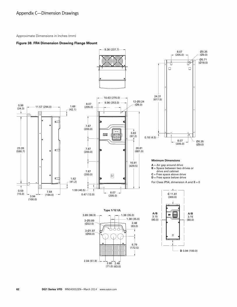
Appendix C—Dimension Drawings
62 DG1 Series VFD MN040002EN—March 2014 www.eaton.com
Approximate Dimensions in Inches (mm)
Figure 38. FR4 Dimension Drawing Flange Mount
REMOTE
RUN
FAULT
STOP
BACK RESET
LOCAL REMOTE
OK START
MS
NS
DANGER5 MIN
REMOTE
RUN
FAULT
STOP
BACK RESET
LOCAL REMOTE
OK START
MS
NS
DANGER5 MIN
A = Air gap around driveB = Space between two drives or drive and cabinetC = Free space above driveD = Free space below drive
Minimum Dimensions
For Class IP54, dimension A and B = 0
C 11.81(300.0)
D 3.94 (100.0)
A/B3.15
(80.0)
A/B3.15
(80.0)
8.07(205.0)
Ø0.35(Ø9.0)
Ø0.71(Ø18.0)
0.18 (4.5)
24.31(617.5)
8.07(205.0)
23.26(590.7)
0.59(15.0) 0.47 (12.0)
9.36 (237.7)
11.57 (294.0)
3.83(97.2)
16.91(429.5)
7.87(200.0)
8.07(205.0)
8.07(205.0)
7.87(200.0)
7.87(200.0)
26.81(681.0)
3.94(100.0)
7.64(194.0)
1.59 (40.5)
1.62(41.2)
1.66(42.1)
0.96(24.3)
10.63 (270.0)
9.96 (253.0) 12-Ø0.24(Ø6.0)
Ø0.35(Ø9.0)
3-Ø0.89(Ø22.5)
2.04 (51.9)2.80
(71.0)2.48
(63.0)
2.48(63.0)
6.79(172.5)
3.89 (98.9)
1.38 (35.0)
1.38 (35.0)
3-Ø1.97(Ø50.0)
Type 1/12 UL

Appendix C—Dimension Drawings
DG1 Series VFD MN040002EN—March 2014 www.eaton.com 63
Approximate Dimensions in Inches (mm)
Figure 39. FR5 Dimension Drawing
30.51(775.0)
Ø0.79 (Ø20.0)
11.34 (288.0)
34.98(888.5)
REMOTE RUN FAULT
STOP
BACKRESET
LOCALREMOTE
OKSTART
REMOTERUNFAULT
STOP
BACKRESET
LOCALREMOTE
OKSTART
A = Air gap around driveB = Space between two drives or drive and cabinetC = Free space above driveD = Free space below drive
Minimum Dimensions
For Class IP54, dimension A and B = 0
C 11.81(300.0)
D 7.87(200.0)
A/B3.15
(80.0)
1.14(29.0)
A/B3.15
(80.0)
11.34 (288.0)11.10(282.0) 8.66
(220.0)
Ø0.35(Ø9.0)Ø0.71
(Ø18.0)
Ø0.89(Ø22.5)
Ø2.95(Ø75.0)
5.51(140.0)
2.52(64.0)
4.21(107.0)
7.76(197.0)
29.65(753.0)
1.57(40.0)
4.09(104.0)
3.83(97.2)
22.57(573.3)
29.65(753.0)
1.08 (27.5)
3.80(96.5)
1.38(35.0)
8.66 (220.0)
1.57(40.0)
8.66(220.0)
Ø0.35(Ø9.0)
Type 1/12 ULIP21/IP54 Metric
140.064.0
197.0
107.0
2-Ø75.03-Ø25.3
40.040.0
104.0

Appendix C—Dimension Drawings
64 DG1 Series VFD MN040002EN—March 2014 www.eaton.com
Approximate Dimensions in Inches (mm)
Figure 40. FR5 Dimension Drawing Flange Mount
REMOTE
RUN
FAULT
STOP
BACK RESET
LOCAL REMOTE
OK START
REMOTE
RUN
FAULT
STOP
BACK RESET
LOCAL REMOTE
OK START
Ø0.35(Ø9.0)Ø0.71
(Ø18.0)
29.65(753.0)
Ø0.35(Ø9.0)
8.66(220.0)
A = Air gap around driveB = Space between two drives or drive and cabinetC = Free space above driveD = Free space below drive
Minimum Dimensions
For Class IP54, dimension A and B = 0
C 11.81(300.0)
D 7.87(200.0)
A/B3.15
(80.0)
A/B3.15
(80.0)
30.51(775.0)
Ø0.79 (Ø20.0)
37.32(948.0)
1.08 (27.5)
5.20(132.0)
1.38(35.0)
8.22(208.7)
1.52(38.5)
0.77(19.5)
8.66 (220.0)
13.41 (340.7)
2.58(65.5)
8.66(220.0)
8.66(220.0)
8.66(220.0)
8.66 (220.0)
3.50(89.0)
0.43(11.0) Ø0.35
(Ø9.0)
3.83(97.2)
12.68(322.0)
13.46 (342.0)
24.09(611.8)
37.32(948.0)
7.01(178.0)
IP21/IP54 Metricand Type 1/12 UL
11.34 (288.0)
Note: With flange kit installed, thebottom wiring box should be removed.

Appendix D—Safety Instructions for UL and cUL
DG1 Series VFD MN040002EN—March 2014 www.eaton.com 65
Appendix D—Safety Instructions for UL and cUL
CAUTIONThe UL and cUL compliance can be maintained only if this driveis installed according to the requirements of Appendix D —Safety Instructions for UL and cUL. Failure to follow theseinstructions may result in UL and cUL non-compliance.
UL Standards Compliance
This drive is tested in accordance with UL508C and CSA C22.2 No. 274-13 and is found to comply with these requirements. To ensure continued compliance when using this drive or when using it in combination with other equipment, meet the following conditions.
General
● This drive should be operated at a maximum ambient temperature of 40°C in low overload (VT) rating and 50°C in high overload (CT) rating
● This drive should be installed in environment of Pollution Degree 2 or better
Overvoltage Category
To comply with standard CSA C22.2 No. 274-13 requirement, the following applies to cUL applications:
● This drive should be installed in environment of Overvoltage Category III
● For 400V Series: Transient surge suppression shall be installed on the line side of this equipment and shall be rated 500V (phase to ground), suitable for Overvoltage Category III, and shall provide protection for a rated impulse withstand voltage peak of 6 kV
● For 230V Series: Transient surge suppression shall be installed on the line side of this equipment and shall be rated 240V (phase to ground), suitable for Overvoltage Category III, and shall provide protection for a rated impulse withstand voltage peak of 4 kV
Motor Overload and Over-Temperature Protection
● This drive provides solid-state motor overload protection that reacts when it reaches 102.5% of FLA
● This drive can accept and act upon a signal from a thermal sensor or switch embedded in the motor or from an external protective relay to achieve the motor over temperature protection. Therefore, in order to achieve the motor over temperature protection, a sensor from the motor will be needed
Branch Circuit Short Circuit Protection
● Integral solid-state short circuit protection does not provide branch circuit protection. Branch circuit protection must be provided in accordance with the National Electrical Code and any additional local codes
● 400V Drive Series are suitable for use on a circuit capable of delivering not more than 100,000 rms symmetrical amperes, 500 volts maximum, when protected by UL and cUL/CSA Recognized Class T fuse with an A.I.C. rating of 100 kA minimum. Refer to the following information for recommended fuse ratings. See Table 39.
Table 39. Fuse Ratings—400V Drive Series
Frame SizeCatalog Number Fuse Rating
1 DG1-342D2xx-xxxx 600V, 10A
DG1-343D3xx-xxxx 600V, 10A
DG1-344D3xx-xxxx 600V, 10A
DG1-345D6xx-xxxx 600V, 10A
DG1-347D6xx-xxxx 600V, 15A
DG1-349D0xx-xxxx 600V, 15A
2 DG1-34012xx-xxxx 600V, 20A
DG1-34016xx-xxxx 600V, 30A
DG1-34023xx-xxxx 600V, 35A
3 DG1-34031xx-xxxx 600V, 50A
DG1-34038xx-xxxx 600V, 60A
DG1-34046xx-xxxx 600V, 80A
4 DG1-34061xx-xxxx 600V, 100A
DG1-34072xx-xxxx 600V, 110A
DG1-34087xx-xxxx 600V, 125A
5 DG1-34105xx-xxxx 600V, 175A
DG1-34140xx-xxxx 600V, 200A
DG1-34170xx-xxxx 600V, 250A

Appendix D—Safety Instructions for UL and cUL
66 DG1 Series VFD MN040002EN—March 2014 www.eaton.com
● 230V Drive Series are suitable for use on a circuit capable of delivering not more than 100,000 rms symmetrical amperes, 240 volts maximum when protected by UL and cUL/CSA Recognized Class T fuse with an A.I.C. rating of 100 kA minimum. Refer to the following information for recommended fuse ratings. See Table 40.
Table 40. Fuse Ratings—230V Drive Series
Field Wiring● The field installed conductors for this drive should be 75°C
copper wire only
● The enclosure openings provided for conduit connections in the field shall be closed by UL Listed conduit fittings with same type rating as the enclosure (Type 1/Type 12)
Line and Motor Wiring
● For 400V Drive Series, required line and motor wire torque, type and size range are listed in Table 41
Table 41. Required Line and Motor Wire Torque (400V)
Frame SizeCatalog Number Fuse Rating
1 DG1-323D7xx-xxxx 600V, 10A
DG1-324D8xx-xxxx 600V, 10A
DG1-326D6xx-xxxx 600V, 10A
DG1-327D8xx-xxxx 600V, 15A
DG1-32011xx-xxxx 600V, 15A
2 DG1-32012xx-xxxx 600V, 20A
DG1-32017xx-xxxx 600V, 30A
DG1-32025xx-xxxx 600V, 35A
3 DG1-32031xx-xxxx 600V, 60A
DG1-32048xx-xxxx 600V, 80A
4 DG1-32061xx-xxxx 600V, 100A
DG1-32075xx-xxxx 600V, 110A
DG1-32088xx-xxxx 600V, 125A
5 DG1-32114xx-xxxx 600V, 175A
DG1-32143xx-xxxx 600V, 200A
DG1-32170xx-xxxx 600V, 250A
Catalog Number Terminal Type
Required Torque (in-lbs)
Required Wire Range
FR1
DG1-342D2xx-xxxx L1, L2, L3, DC+, DC–, R+, R–, U, V, W
5–7 14–10 AWG
DG1-343D3xx-xxxx 5–7 14–10 AWG
DG1-344D3xx-xxxx 5–7 14–10 AWG
DG1-345D6xx-xxxx 5–7 14–10 AWG
DG1-347D6xx-xxxx 5–7 14–10 AWG
DG1-349D0xx-xxxx 5–7 14–10 AWG
FR2
DG1-34012xx-xxxx L1, L2, L3, DC+, DC–, R+, R–, U, V, W
15.6 12–6 AWG
DG1-34016xx-xxxx 15.6 10–6 AWG
DG1-34023xx-xxxx 15.6 8–6 AWG
FR3
DG1-34031xx-xxxx L1, L2, L3, DC+, DC–, R+, R–, U, V, W
40 8–2 AWG
DG1-34038xx-xxxx 40 6–2 AWG
DG1-34046xx-xxxx 40 4–2 AWG
FR4
DG1-34061xx-xxxx L1, L2, L3, DC+, DC–, R+, R–, U, V, W
95 4–1/0 AWG
DG1-34072xx-xxxx 95 3–1/0 AWG
DG1-34087xx-xxxx 95 1–1/0 AWG
FR5
DG1-34105xx-xxxx L1, L2, L3, DC+, DC–, R+, R–, U, V, W
354 2/0 AWG–350 kcmil
DG1-34140xx-xxxx 354 3/0 AWG–350 kcmil
DG1-34170xx-xxxx 354 250–350 kcmil
All Frames Sizes (FR1–FR5)
All models Control terminal block
4.5 28~12 (Sol) AWG30~12 (Str) AWG

Appendix D—Safety Instructions for UL and cUL
DG1 Series VFD MN040002EN—March 2014 www.eaton.com 67
● For 230V Drive Series, required line and motor wire torque, type and size range are listed in Table 42
Table 42. Required Line and Motor Wire Torque (230V)
Note1 The line and motor wire size for DG1-32088xx-xxxx can only be 1/0 AWG.
Grounding
● For 400V Drive Series, required grounding wire torque, type and size range are listed in Table 43
Table 43. Required Line and Motor Wire Torque (400V) Catalog Number Terminal Type
Required Torque (in-lb)
Required Wire Range
FR1
DG1-323D7xx-xxxx L1, L2, L3, DC+, DC–, R+, R–, U, V, W
12.1 14–10 AWG
DG1-324D8xx-xxxx 12.1 14–10 AWG
DG1-326D6xx-xxxx 12.1 14–10 AWG
DG1-327D8xx-xxxx 12.1 14–10 AWG
DG1-32011xx-xxxx 12.1 12–10 AWG
FR2
DG1-32012xx-xxxx L1, L2, L3, DC+, DC–, R+, R–, U, V, W
15.6 10–6 AWG
DG1-32017xx-xxxx 15.6 8–6 AWG
DG1-32025xx-xxxx 15.6 8–6 AWG
FR3
DG1-32031xx-xxxx L1, L2, L3, DC+, DC–, R+, R–, U, V, W
40 6–2 AWG
DG1-32048xx-xxxx 40 4–2 AWG
FR4
DG1-32061xx-xxxx L1, L2, L3, DC+, DC–, R+, R–, U, V, W
95 3–1/0 AWG
DG1-32075xx-xxxx 95 2–1/0 AWG
DG1-32088xx-xxxx 95 1/0 AWG 1
FR5
DG1-32114xx-xxxx L1, L2, L3, DC+, DC–, R+, R–, U, V, W
354 3/0 AWG–350 kcmil
DG1-32143xx-xxxx 354 4/0 AWG–350 kcmil
DG1-32170xx-xxxx 354 300–350 kcmil
All Frames Sizes (FR1–FR5)
All models Control terminal block
4.5 28~12 (Sol) AWG30~12 (Str) AWG
Catalog Number Terminal Type
Required Torque (in-lb)
Required Wire Range
FR1
DG1-342D2xx-xxxx Grounding terminal 10 14–10 AWG
DG1-343D3xx-xxxx 10 14–10 AWG
DG1-344D3xx-xxxx 10 14–10 AWG
DG1-345D6xx-xxxx 10 14–10 AWG
DG1-347D6xx-xxxx 10 14–10 AWG
DG1-349D0xx-xxxx 10 14–10 AWG
FR2
DG1-34012xx-xxxx Grounding terminal 10 12–6 AWG
DG1-34016xx-xxxx 10 10–6 AWG
DG1-34023xx-xxxx 10 10–6 AWG
FR3
DG1-34031xx-xxxx Grounding terminal 10 10–4 AWG
DG1-34038xx-xxxx 10 10–4 AWG
DG1-34046xx-xxxx 10 8–4 AWG
FR4
DG1-34061xx-xxxx Grounding terminal 14 8–1/0 AWG
DG1-34072xx-xxxx 14 6–1/0 AWG
DG1-34087xx-xxxx 14 6–1/0 AWG
FR5
DG1-34105xx-xxxx Grounding terminal 35 6 AWG–250 kcmil
DG1-34140xx-xxxx 35 6 AWG–250 kcmil
DG1-34170xx-xxxx 35 4 AWG–250 kcmil

Appendix D—Safety Instructions for UL and cUL
68 DG1 Series VFD MN040002EN—March 2014 www.eaton.com
● For 230V Drive Series, required grounding wire torque, type and size range are listed as below:
Table 44. Required Line and Motor Wire Torque (230V)
Catalog Number Terminal Type
Required Torque (in-lb)
Required Wire Range
FR1
DG1-323D7xx-xxxx Grounding terminal 10 14–10 AWG
DG1-324D8xx-xxxx 10 14–10 AWG
DG1-326D6xx-xxxx 10 14–10 AWG
DG1-327D8xx-xxxx 10 14–10 AWG
DG1-32011xx-xxxx 10 14–10 AWG
FR2
DG1-32012xx-xxxx Grounding terminal 10 12–6 AWG
DG1-32017xx-xxxx 10 10–6 AWG
DG1-32025xx-xxxx 10 10–6 AWG
FR3
DG1-32031xx-xxxx Grounding terminal 10 10–4 AWG
DG1-32048xx-xxxx 10 10–4 AWG
FR4
DG1-32061xx-xxxx Grounding terminal 14 8–1/0 AWG
DG1-32075xx-xxxx 14 6–1/0 AWG
DG1-32088xx-xxxx 14 6–1/0 AWG
FR5
DG1-32114xx-xxxx Grounding terminal 35 6 AWG–250 kcmil
DG1-32143xx-xxxx 35 6 AWG–250 kcmil
DG1-32170xx-xxxx 35 4 AWG–250 kcmil


Eaton is a registered trademark.
All other trademarks are property of their respective owners.
Eaton is dedicated to ensuring that reliable, efficient and safe power is available when it’s needed most. With unparalleled knowledge of electrical power management across industries, experts at Eaton deliver customized, integrated solutions to solve our customers’ most critical challenges.
Our focus is on delivering the right solution for the application. But, decision makers demand more than just innovative products. They turn to Eaton for an unwavering commitment to personal support that makes customer success a top priority. For more information, visit www.eaton.com/electrical.
Eaton1000 Eaton BoulevardCleveland, OH 44122 United StatesEaton.com
© 2014 EatonAll Rights ReservedPrinted in USAPublication No. MN040002EN / Z14910March 2014