ppt design project - university of...
TRANSCRIPT
PPT Design Project
ENAE483 November 8, 2010 Stef Bilyk, Kip Hart,
John Pino, Tim Russell
Project Overview
1) Design the power system, reaction control system,
and perform the thermal equilibrium calculations for the
human spacecraft from the Crew Systems project.
2) Gross mass of the two projects = 4795 kg
Reaction Control System Specifications
1) Design a reaction control system for the human
spacecraft chosen
• Must be capable of limited 6 DOF control
– Translational ΔV of 50 m/sec
– Attitude hold in dead band for three days (return
to Earth)
– Able to overcome entry aerodynamic moments
of 500 Nm in pitch and yaw
– Able to rotate spacecraft 180° in roll ≤30 sec on
entry
Power System Specifications
1) Design a power system to provide electrical power to
the spacecraft throughout the mission (with duration
margin from last time)
2) Must support all mission phases
– LEO checkout
– Cis-lunar space
– LLO loiter
– Lunar descent and ascent
– Lunar surface operations
– Earth EDL
Thermal Control System Specifications
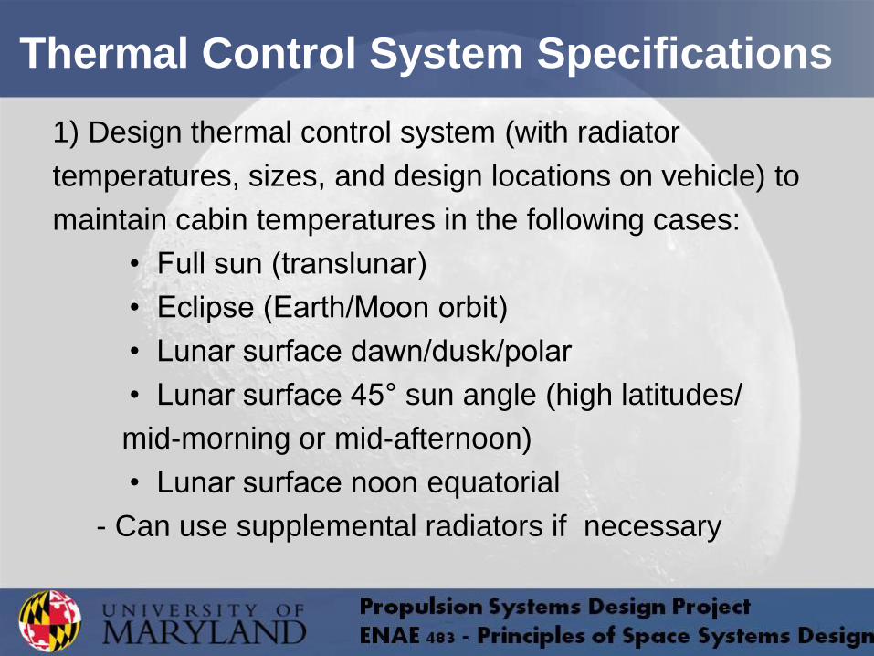
1) Design thermal control system (with radiator
temperatures, sizes, and design locations on vehicle) to
maintain cabin temperatures in the following cases:
• Full sun (translunar)
• Eclipse (Earth/Moon orbit)
• Lunar surface dawn/dusk/polar
• Lunar surface 45° sun angle (high latitudes/
mid-morning or mid-afternoon)
• Lunar surface noon equatorial
- Can use supplemental radiators if necessary
• Selection: Team A10
– Full list of detailed power requirements
– Sufficient volume for propellant, batteries, or other
energy storage devices in design
– Total mass was well below maximum
– Most through descriptions of crew systems
components
– Simplicity of atmosphere and other designs
Crew Systems Design Project Selection
Propulsion System Specifications
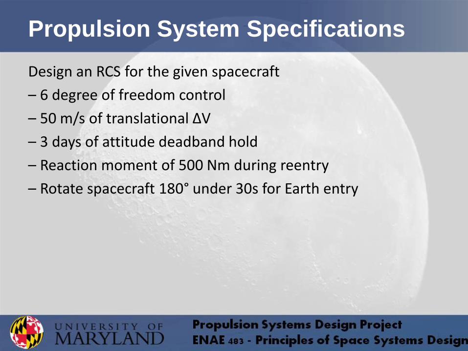
Design an RCS for the given spacecraft
– 6 degree of freedom control
– 50 m/s of translational ∆V
– 3 days of attitude deadband hold
– Reaction moment of 500 Nm during reentry
– Rotate spacecraft 180° under 30s for Earth entry
RCS - 6DOF Control
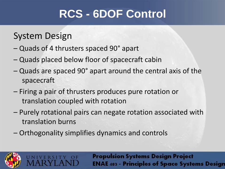
System Design – Quads of 4 thrusters spaced 90° apart
– Quads placed below floor of spacecraft cabin
– Quads are spaced 90° apart around the central axis of the spacecraft
– Firing a pair of thrusters produces pure rotation or translation coupled with rotation
– Purely rotational pairs can negate rotation associated with translation burns
– Orthogonality simplifies dynamics and controls
RCS - 50 m/s Translational ∆V
– Force generated by 4 thrusters
– Vectors pointed towards tip of cone, normal to floor
– Consider orthogonal for initial design considerations
– Approx. with constant mass during ∆V
16 kNs impulse required from each thruster
60 mN minimum thrust
RCS - Attitude Deadband
– Deadband hold at ±5°
– Consider impulsive deadband maneuvers
– Spacecraft oscillates between deadband maxima
– Consider 14 impulses over 3 days
1.5 Ns impulse required from each thruster
0.12 mN minimum thrust
RCS - Reentry Moments
– Given moments of 500 Nm
– Moments experienced over 10 minutes of reentry
– Static equilibrium from opposing thrusters producing 156 N
– Assume a constant hold over entire reentry
94 kNs impulse required from each thruster
156 N force applied by each thruster

RCS - Half turns under 30s
– Provide for 10 turns during mission
– Minimum angular velocity of 6 deg/s
– Assume constant thrust
𝜃 =𝜋
450
𝑟𝑎𝑑
𝑠2
12 kNs impulse required from each thruster
40 N force applied by each thruster
𝜃 =𝜋
900
𝑟𝑎𝑑
𝑠2𝑡2

RCS - Thrust and Impulse Summary
Requirement Thrust (N) Impulse (kNs)
Translational ∆V ≥0.032 16
Attitude Deadband ≥0.00012 0.0015
Reentry Moments 160 94
Half Turns ≥40 12
RCS - Analysis of Initial Design
– Large force requirements
+ Aerodynamic moments during reentry
+ Half turns
– Minimal force requirements
+ Translational ∆V
+ Attitude Deadband
Consider single system for moments and half turns

RCS - Large Force System
– Consider 160 N thrusters
– Thrusters controlled by solenoids, no throttle
– Assess force transmission to astronauts
𝑎𝑡𝑟𝑎𝑛𝑠 = 6 × 10⁻³ 𝑔
160 N cause acceptably low accelerations on crew
𝐹𝑡𝑟𝑎𝑛𝑠 = (4 × 10−3) × 160 𝑁
RCS - Large Force System Selection
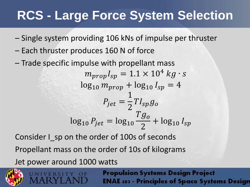
– Single system providing 106 kNs of impulse per thruster
– Each thruster produces 160 N of force
– Trade specific impulse with propellant mass 𝑚𝑝𝑟𝑜𝑝𝐼𝑠𝑝 = 1.1 × 10⁴ 𝑘𝑔 ∙ 𝑠
log10𝑚𝑝𝑟𝑜𝑝 + log10 𝐼𝑠𝑝 = 4
𝑃𝑗𝑒𝑡 =1
2𝑇𝐼𝑠𝑝𝑔𝑜
log10 𝑃𝑗𝑒𝑡 = log10𝑇𝑔𝑜2
+ log10 𝐼𝑠𝑝
Consider I_sp on the order of 100s of seconds
Propellant mass on the order of 10s of kilograms
Jet power around 1000 watts
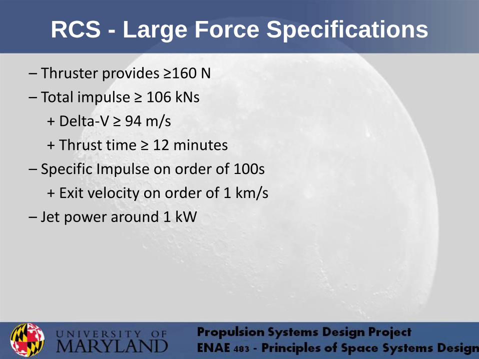
RCS - Large Force Specifications
– Thruster provides ≥160 N
– Total impulse ≥ 106 kNs
+ Delta-V ≥ 94 m/s
+ Thrust time ≥ 12 minutes
– Specific Impulse on order of 100s
+ Exit velocity on order of 1 km/s
– Jet power around 1 kW

Thrust Requirement
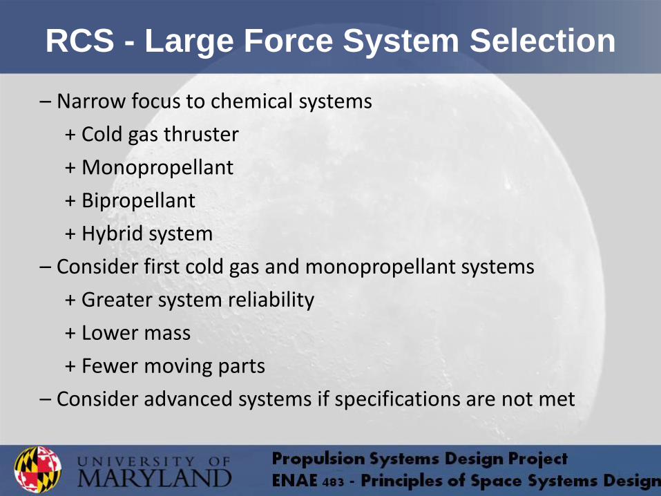
RCS - Large Force System Selection
– Narrow focus to chemical systems
+ Cold gas thruster
+ Monopropellant
+ Bipropellant
+ Hybrid system
– Consider first cold gas and monopropellant systems
+ Greater system reliability
+ Lower mass
+ Fewer moving parts
– Consider advanced systems if specifications are not met
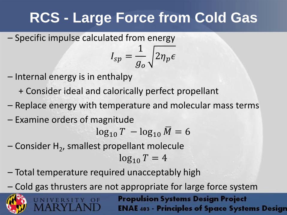
RCS - Large Force from Cold Gas
– Specific impulse calculated from energy
𝐼𝑠𝑝 =1
𝑔𝑜2𝜂𝑝𝜖
– Internal energy is in enthalpy
+ Consider ideal and calorically perfect propellant
– Replace energy with temperature and molecular mass terms
– Examine orders of magnitude log10 𝑇 − log10𝑀 = 6
– Consider H2, smallest propellant molecule log10 𝑇 = 4
– Total temperature required unacceptably high
– Cold gas thrusters are not appropriate for large force system
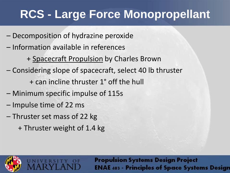
RCS - Large Force Monopropellant
– Decomposition of hydrazine peroxide
– Information available in references
+ Spacecraft Propulsion by Charles Brown
– Considering slope of spacecraft, select 40 lb thruster
+ can incline thruster 1° off the hull
– Minimum specific impulse of 115s
– Impulse time of 22 ms
– Thruster set mass of 22 kg
+ Thruster weight of 1.4 kg
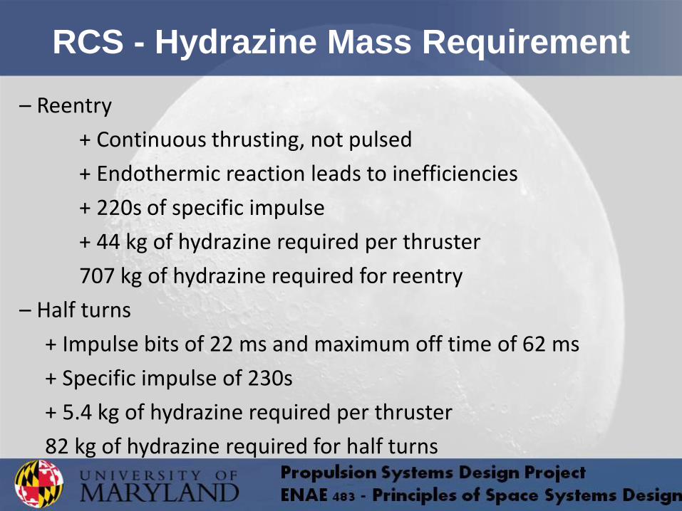
RCS - Hydrazine Mass Requirement
– Reentry
+ Continuous thrusting, not pulsed
+ Endothermic reaction leads to inefficiencies
+ 220s of specific impulse
+ 44 kg of hydrazine required per thruster
707 kg of hydrazine required for reentry
– Half turns
+ Impulse bits of 22 ms and maximum off time of 62 ms
+ Specific impulse of 230s
+ 5.4 kg of hydrazine required per thruster
82 kg of hydrazine required for half turns
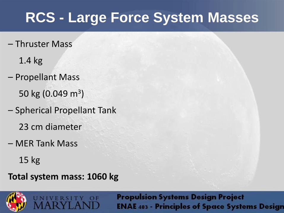
RCS - Large Force System Masses
– Thruster Mass
1.4 kg
– Propellant Mass
50 kg (0.049 m3)
– Spherical Propellant Tank
23 cm diameter
– MER Tank Mass
15 kg
Total system mass: 1060 kg

RCS - Minimal Force System
– Minimal force requirements
+ Translational ∆V
+ Attitude Deadband
– Total impulse required is 16 kNs
– Desire high thrust for ∆V and low thrust for attitude
+ Need to throttle propellants to achieve both goals
+ Reconsider cold gas thruster
– Position thruster components above CTBs inside capsule
– Four groups of two thrusters positioned orthogonally
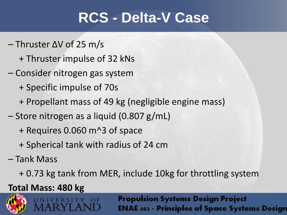
RCS - Delta-V Case
– Thruster ∆V of 25 m/s
+ Thruster impulse of 32 kNs
– Consider nitrogen gas system
+ Specific impulse of 70s
+ Propellant mass of 49 kg (negligible engine mass)
– Store nitrogen as a liquid (0.807 g/mL)
+ Requires 0.060 m^3 of space
+ Spherical tank with radius of 24 cm
– Tank Mass
+ 0.73 kg tank from MER, include 10kg for throttling system
Total Mass: 480 kg
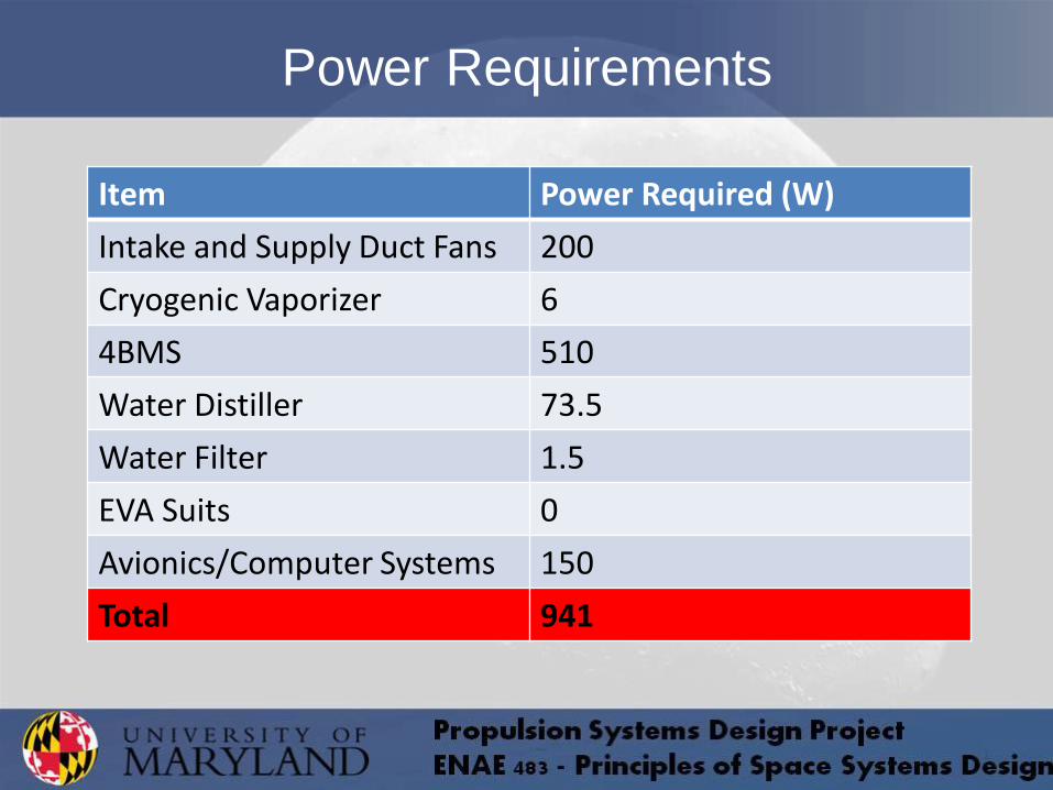
Power Requirements
Item Power Required (W)
Intake and Supply Duct Fans 200
Cryogenic Vaporizer 6
4BMS 510
Water Distiller 73.5
Water Filter 1.5
EVA Suits 0
Avionics/Computer Systems 150
Total 941
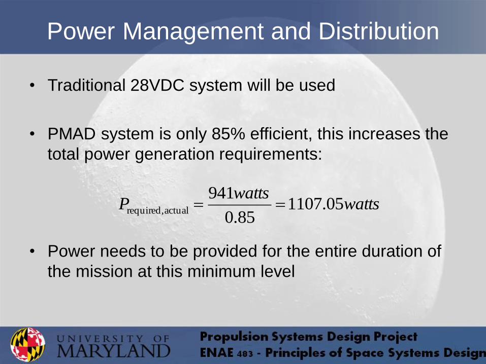
• Traditional 28VDC system will be used
• PMAD system is only 85% efficient, this increases the
total power generation requirements:
• Power needs to be provided for the entire duration of
the mission at this minimum level
Power Management and Distribution
wattswatts
P 05.110785.0
941actual required,

• There are a number of different combinations of power
generation and energy storage in space that may be
appropriate for this mission:
– Solar arrays and batteries
– Fuel cells
– RTGs
– Batteries only
• The ideal system for a manned mission would be safe,
relatively light, not overly complex, and well-tested.
Power Generation and Energy Storage
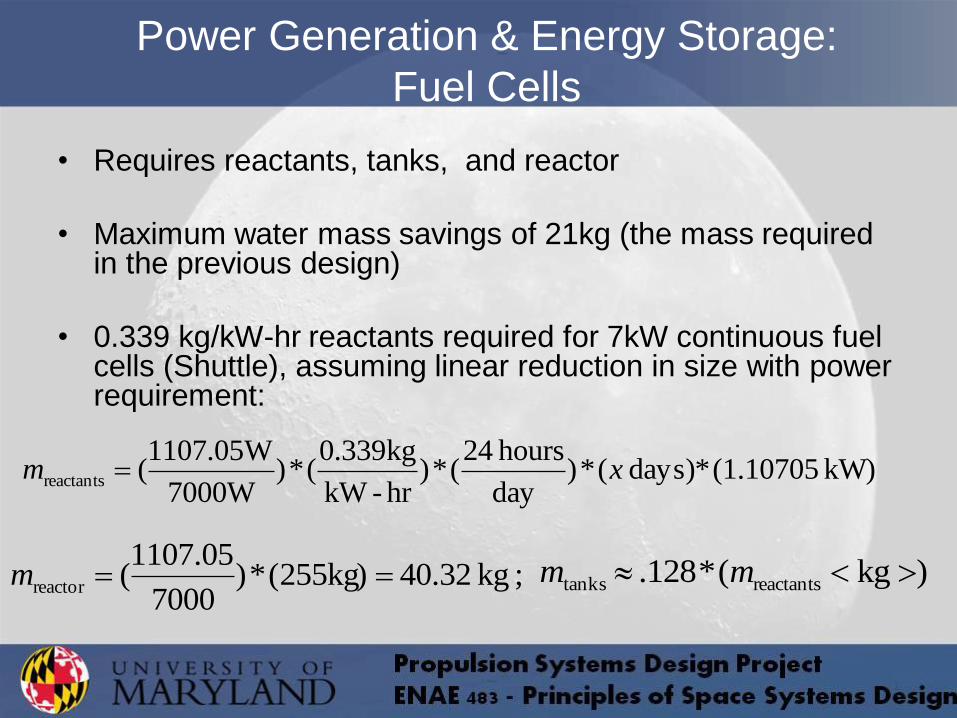
Power Generation & Energy Storage:
Fuel Cells
• Requires reactants, tanks, and reactor
• Maximum water mass savings of 21kg (the mass required in the previous design)
• 0.339 kg/kW-hr reactants required for 7kW continuous fuel cells (Shuttle), assuming linear reduction in size with power requirement:
kW) (1.10705*days) (*)day
hours 24(*)
hr-kW
kg339.0(*)
7000W
W05.1107(reactants xm
; kg 40.32 kg)255(*)7000
05.1107(reactor m )kg(*128. reactantstanks mm
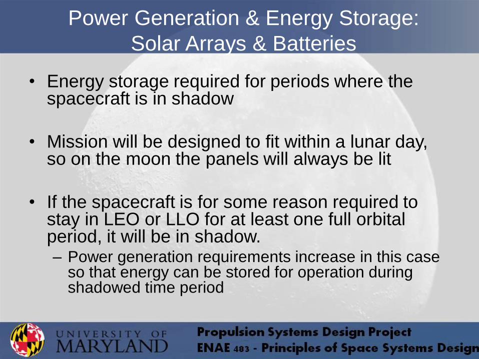
Power Generation & Energy Storage:
Solar Arrays & Batteries
• Energy storage required for periods where the spacecraft is in shadow
• Mission will be designed to fit within a lunar day, so on the moon the panels will always be lit
• If the spacecraft is for some reason required to stay in LEO or LLO for at least one full orbital period, it will be in shadow. – Power generation requirements increase in this case
so that energy can be stored for operation during shadowed time period
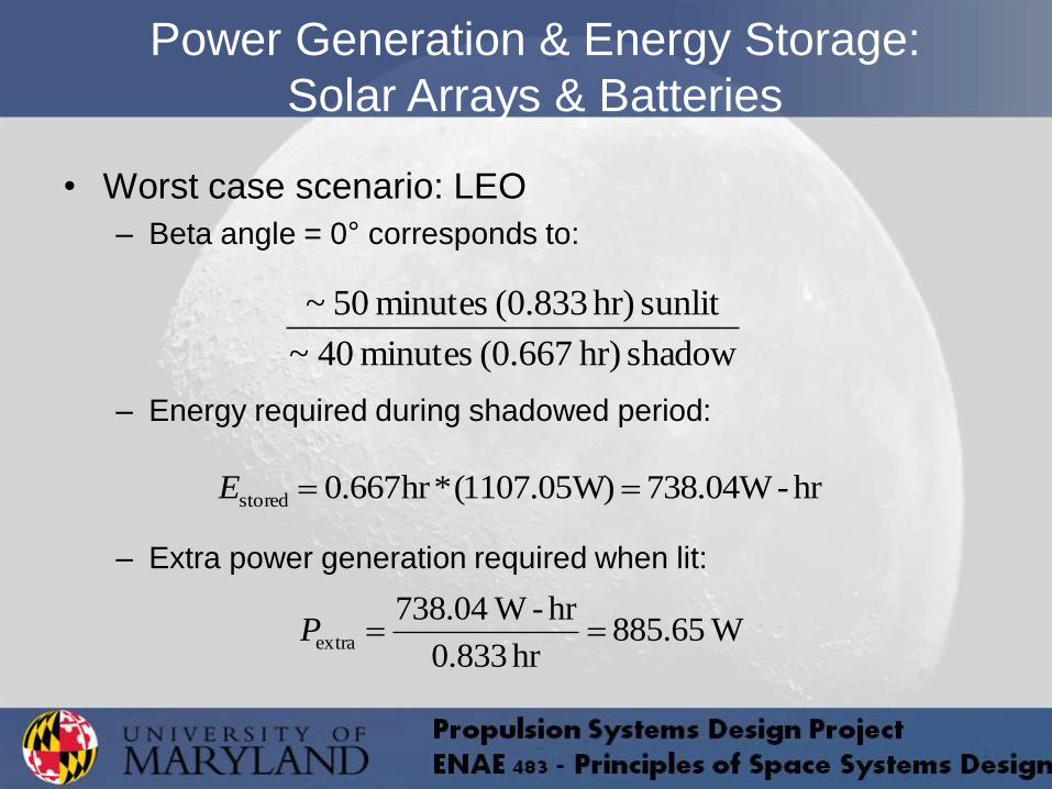
• Worst case scenario: LEO
– Beta angle = 0° corresponds to:
– Energy required during shadowed period:
– Extra power generation required when lit:
Power Generation & Energy Storage:
Solar Arrays & Batteries
shadow hr) (0.667 minutes 40~
sunlit hr) (0.833 minutes 50~
hr-738.04W W)05.1107(*hr667.0stored E
W65.885hr 0.833
hr- W04.738extra P
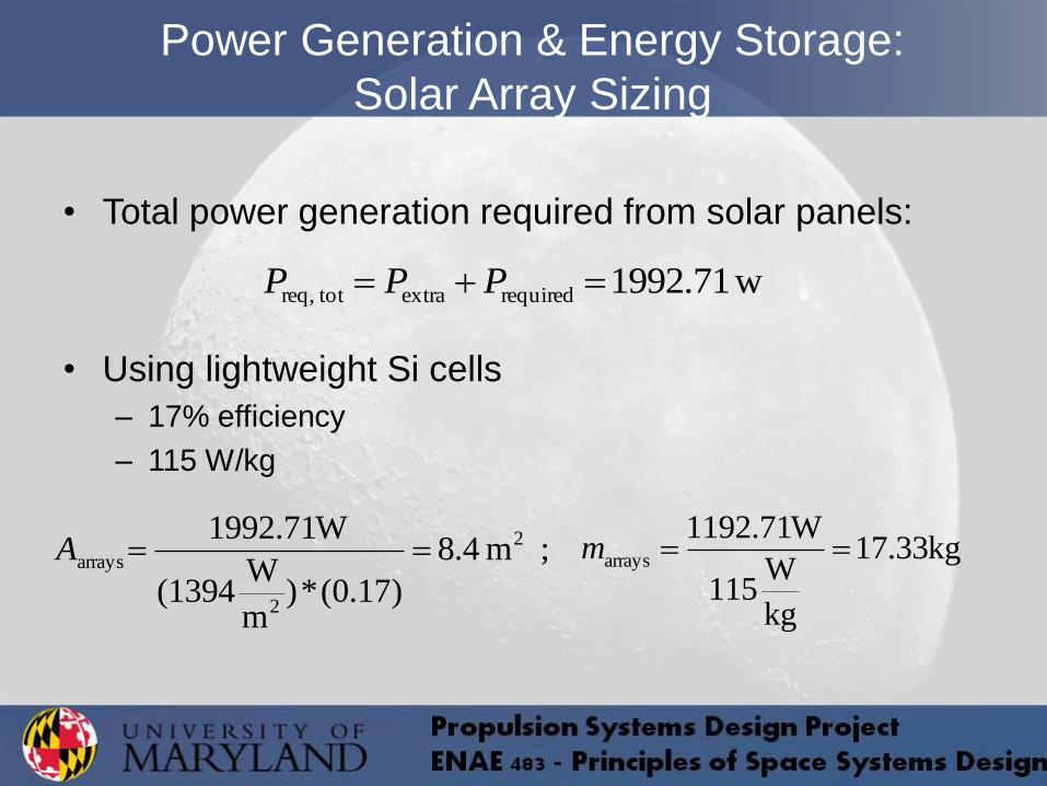
• Total power generation required from solar panels:
• Using lightweight Si cells
– 17% efficiency
– 115 W/kg
Power Generation & Energy Storage:
Solar Array Sizing
w1992.71requiredextra totreq, PPP
; m 4.8
)17.0(*)m
W(1394
W71.1992 2
2
arrays A kg33.17
kg
W115
W71.1192arrays m
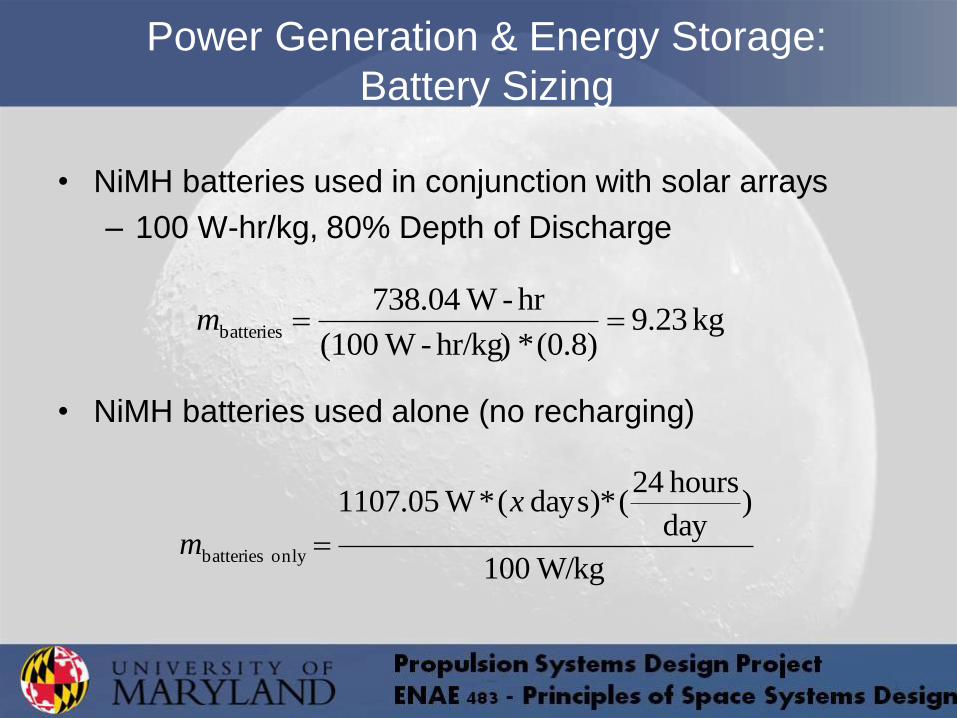
• NiMH batteries used in conjunction with solar arrays
– 100 W-hr/kg, 80% Depth of Discharge
• NiMH batteries used alone (no recharging)
Power Generation & Energy Storage:
Battery Sizing
kg 23.9(0.8)*hr/kg)- W(100
hr- W04.738batteries m
W/kg100
)day
hours 24(*days) (* W05.1107
only batteries
x
m
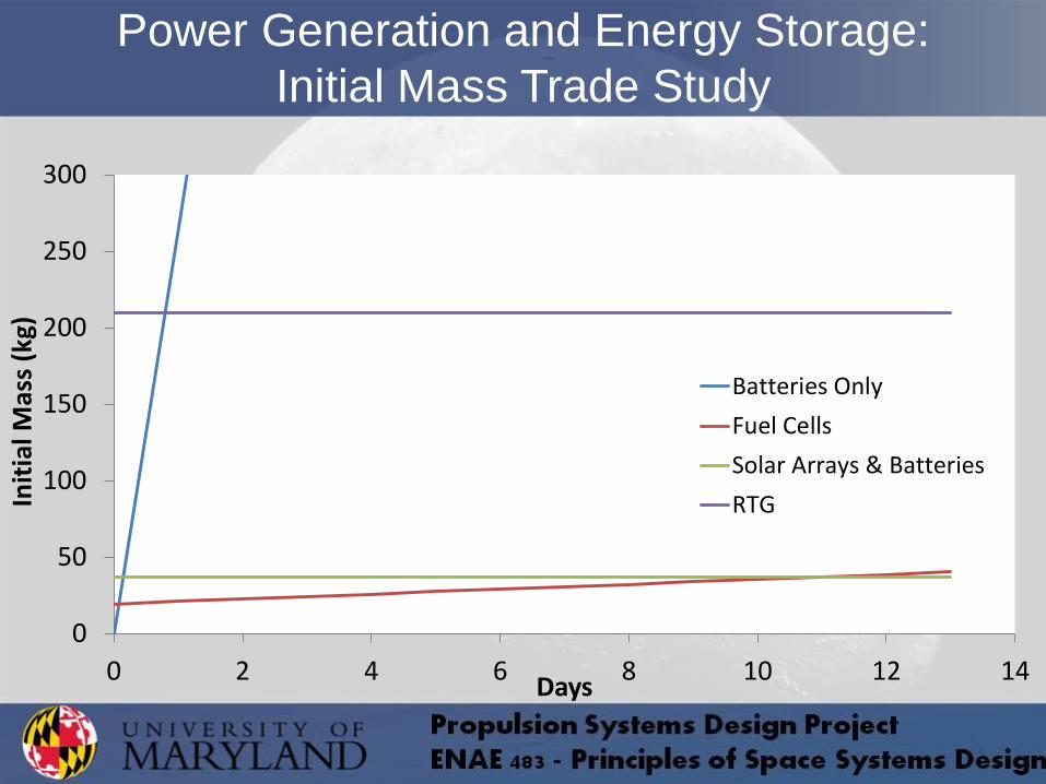
Power Generation and Energy Storage:
Initial Mass Trade Study
0
50
100
150
200
250
300
0 2 4 6 8 10 12 14
Init
ial M
ass
(kg)
Days
Batteries Only
Fuel Cells
Solar Arrays & Batteries
RTG

• With increasing mission length, using only batteries
quickly becomes extremely heavy and unreasonable.
• Fuel cells are relatively lightweight, but are expensive
and complicated
• RTGs at this power level (based on those designed for
Galileo) are heavy, generate a great deal of excess
heat, and it is beneficial to avoid radioactive power
generation for human missions
Power Generation and Energy Storage
Summary
• Solar panels combined with batteries provide the lightest and simplest option for power generation and storage
• The required area of 8.4 m2 is also very reasonable
• The mission will be timed so that the entire surface mission will be in sunlight
• The mass of batteries needed (10kg) to survive up to 40 minute periods of shadowing with only 50 minute periods of sun is well within the space and mass constraints of the capsule
– These batteries are also sufficient to provide power during Lunar landing, Earth re-entry, and any other large maneuvers that require either the stowage or redirecting of the solar arrays
Power Generation and Energy Storage
Summary
Solar Array Design
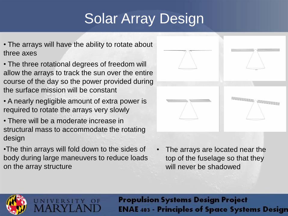
• The arrays will have the ability to rotate about
three axes
• The three rotational degrees of freedom will
allow the arrays to track the sun over the entire
course of the day so the power provided during
the surface mission will be constant
• A nearly negligible amount of extra power is
required to rotate the arrays very slowly
• There will be a moderate increase in
structural mass to accommodate the rotating
design
•The thin arrays will fold down to the sides of
body during large maneuvers to reduce loads
on the array structure
• The arrays are located near the
top of the fuselage so that they
will never be shadowed
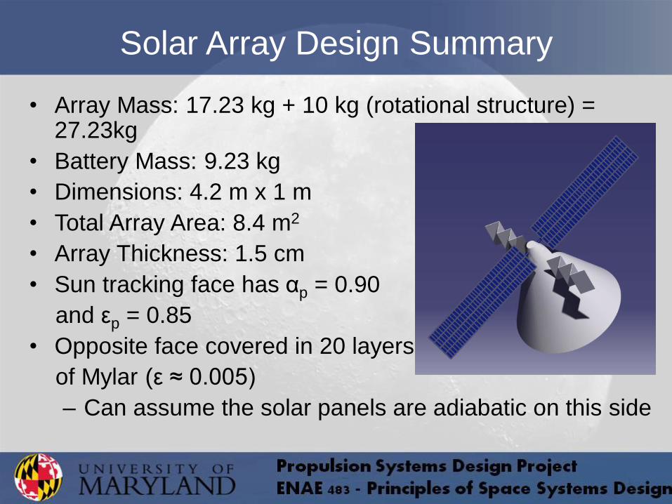
• Array Mass: 17.23 kg + 10 kg (rotational structure) = 27.23kg
• Battery Mass: 9.23 kg
• Dimensions: 4.2 m x 1 m
• Total Array Area: 8.4 m2
• Array Thickness: 1.5 cm
• Sun tracking face has αp = 0.90
and εp = 0.85
• Opposite face covered in 20 layers
of Mylar (ε ≈ 0.005)
– Can assume the solar panels are adiabatic on this side
Solar Array Design Summary
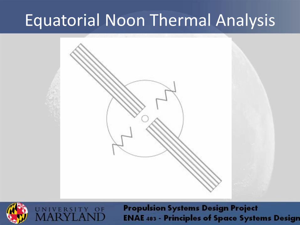
Equatorial Noon Thermal Analysis

• Assume that all of the electrical power used onboard the spacecraft is eventually converted into heat
• Also assume that humans produce heat
• During high incident light periods, all internally generated power will need to be radiated
• During eclipse periods, not all internal power will be removed from the atmosphere in order to keep the cabin temperature at appropriate levels
Internal Power Generated
W05.1107yElectricitP
W348 people) 3(*)person
W 116( HumansP
W05.1455InternalP
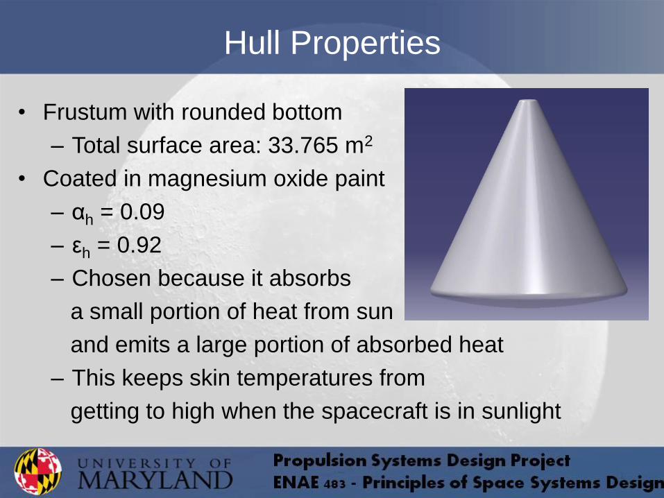
Hull Properties
• Frustum with rounded bottom
– Total surface area: 33.765 m2
• Coated in magnesium oxide paint
– αh = 0.09
– εh = 0.92
– Chosen because it absorbs
a small portion of heat from sun
and emits a large portion of absorbed heat
– This keeps skin temperatures from
getting to high when the spacecraft is in sunlight
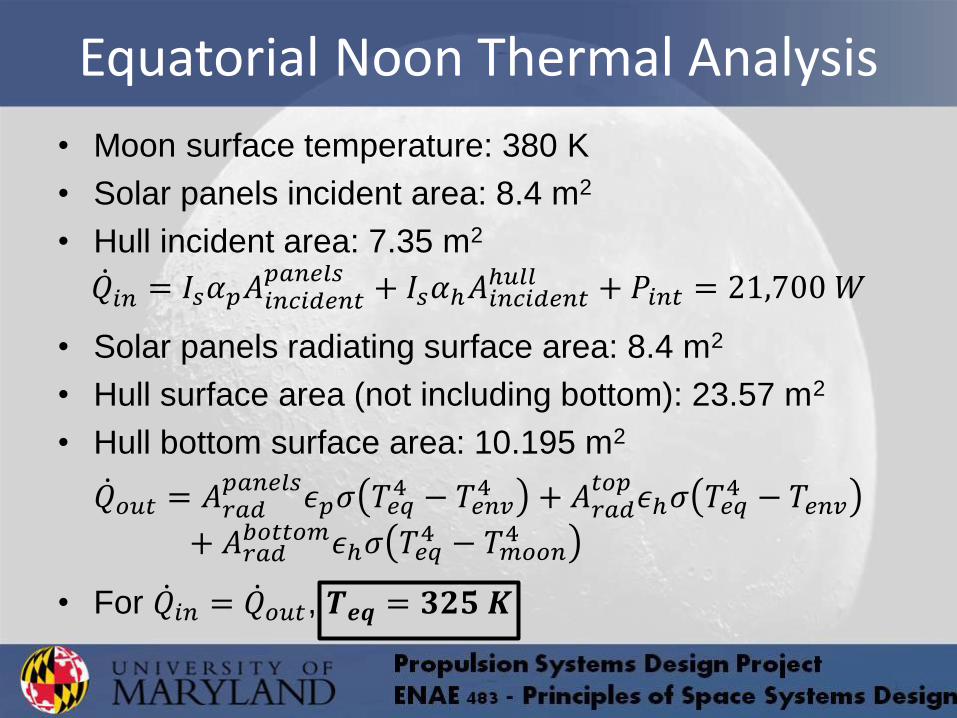
Equatorial Noon Thermal Analysis
• Moon surface temperature: 380 K
• Solar panels incident area: 8.4 m2
• Hull incident area: 7.35 m2
𝑄 𝑖𝑛 = 𝐼𝑠𝛼𝑝𝐴𝑖𝑛𝑐𝑖𝑑𝑒𝑛𝑡𝑝𝑎𝑛𝑒𝑙𝑠
+ 𝐼𝑠𝛼ℎ𝐴𝑖𝑛𝑐𝑖𝑑𝑒𝑛𝑡ℎ𝑢𝑙𝑙 + 𝑃𝑖𝑛𝑡 = 21,700 𝑊
• Solar panels radiating surface area: 8.4 m2
• Hull surface area (not including bottom): 23.57 m2
• Hull bottom surface area: 10.195 m2
𝑄 𝑜𝑢𝑡 = 𝐴𝑟𝑎𝑑𝑝𝑎𝑛𝑒𝑙𝑠
𝜖𝑝𝜎 𝑇𝑒𝑞4 − 𝑇𝑒𝑛𝑣
4 + 𝐴𝑟𝑎𝑑𝑡𝑜𝑝
𝜖ℎ𝜎 𝑇𝑒𝑞4 − 𝑇𝑒𝑛𝑣
+ 𝐴𝑟𝑎𝑑𝑏𝑜𝑡𝑡𝑜𝑚𝜖ℎ𝜎 𝑇𝑒𝑞
4 − 𝑇𝑚𝑜𝑜𝑛4
• For 𝑄 𝑖𝑛 = 𝑄 𝑜𝑢𝑡, 𝑻𝒆𝒒 = 𝟑𝟐𝟓 𝑲
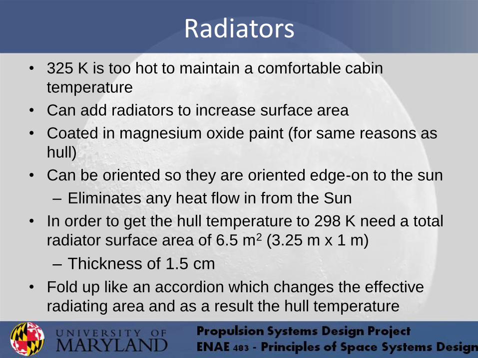
Radiators • 325 K is too hot to maintain a comfortable cabin
temperature
• Can add radiators to increase surface area
• Coated in magnesium oxide paint (for same reasons as
hull)
• Can be oriented so they are oriented edge-on to the sun
– Eliminates any heat flow in from the Sun
• In order to get the hull temperature to 298 K need a total
radiator surface area of 6.5 m2 (3.25 m x 1 m)
– Thickness of 1.5 cm
• Fold up like an accordion which changes the effective
radiating area and as a result the hull temperature
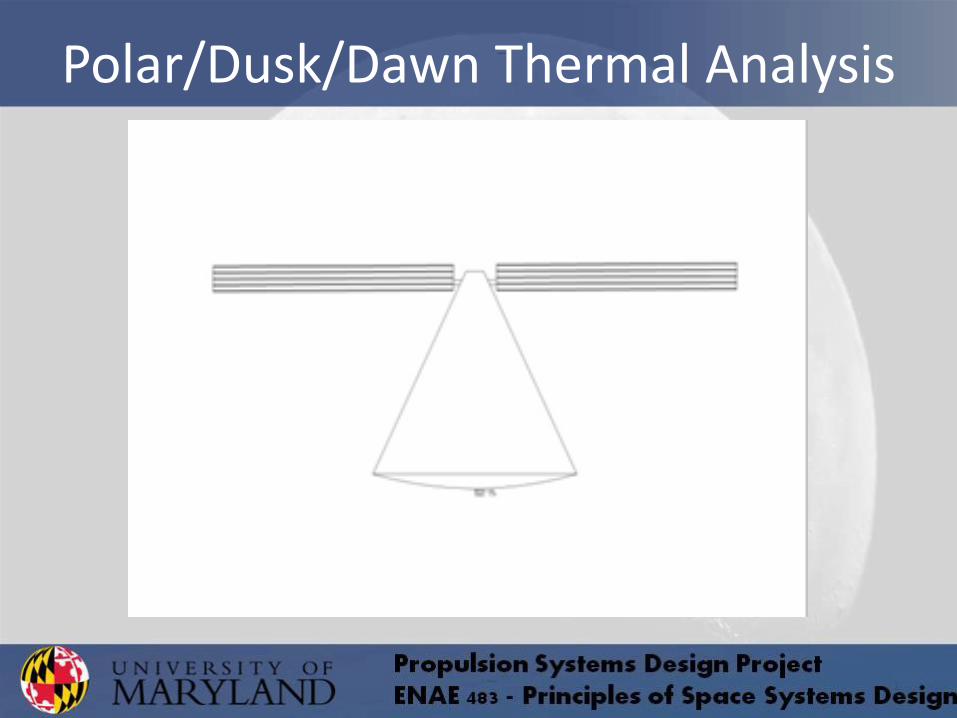
Polar/Dusk/Dawn Thermal Analysis
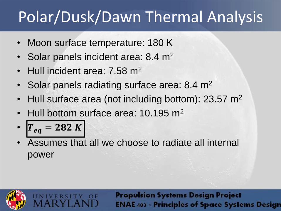
Polar/Dusk/Dawn Thermal Analysis
• Moon surface temperature: 180 K
• Solar panels incident area: 8.4 m2
• Hull incident area: 7.58 m2
• Solar panels radiating surface area: 8.4 m2
• Hull surface area (not including bottom): 23.57 m2
• Hull bottom surface area: 10.195 m2
• 𝑻𝒆𝒒 = 𝟐𝟖𝟐 𝑲
• Assumes that all we choose to radiate all internal
power
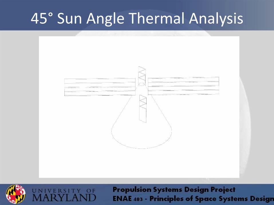
45° Sun Angle Thermal Analysis
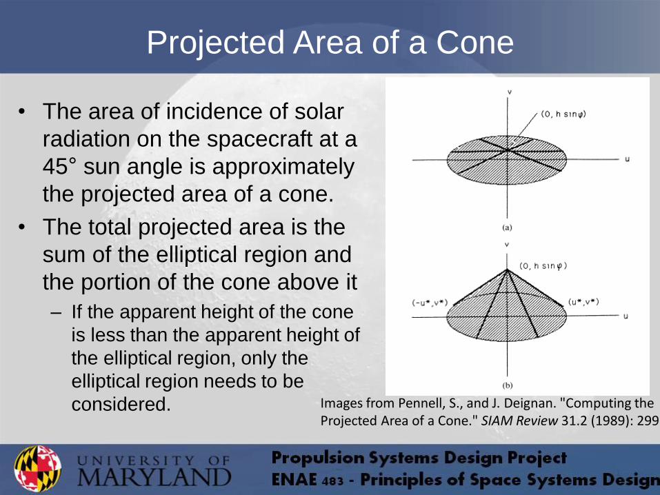
Projected Area of a Cone
• The area of incidence of solar
radiation on the spacecraft at a
45° sun angle is approximately
the projected area of a cone.
• The total projected area is the
sum of the elliptical region and
the portion of the cone above it
– If the apparent height of the cone
is less than the apparent height of
the elliptical region, only the
elliptical region needs to be
considered.
Images from Pennell, S., and J. Deignan. "Computing the Projected Area of a Cone." SIAM Review 31.2 (1989): 299
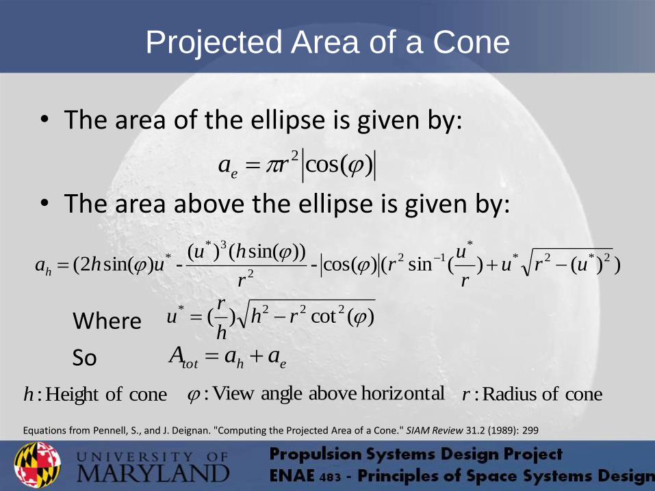
• The area of the ellipse is given by:
• The area above the ellipse is given by:
Where
So
Projected Area of a Cone
)(cos2 rae
))()(sin()(cos-))sin(()(
-)sin(2( 2*2**
12
2
3** uru
r
ur
r
huuhah
)(cot)( 222* rhh
ru
ehtot aaA
cone ofHeight :h horizontal above angle View : cone of Radius :r
Equations from Pennell, S., and J. Deignan. "Computing the Projected Area of a Cone." SIAM Review 31.2 (1989): 299
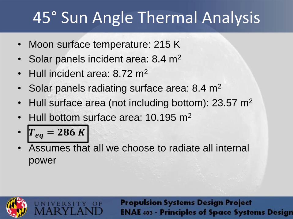
45° Sun Angle Thermal Analysis
• Moon surface temperature: 215 K
• Solar panels incident area: 8.4 m2
• Hull incident area: 8.72 m2
• Solar panels radiating surface area: 8.4 m2
• Hull surface area (not including bottom): 23.57 m2
• Hull bottom surface area: 10.195 m2
• 𝑻𝒆𝒒 = 𝟐𝟖𝟔 𝑲
• Assumes that all we choose to radiate all internal
power
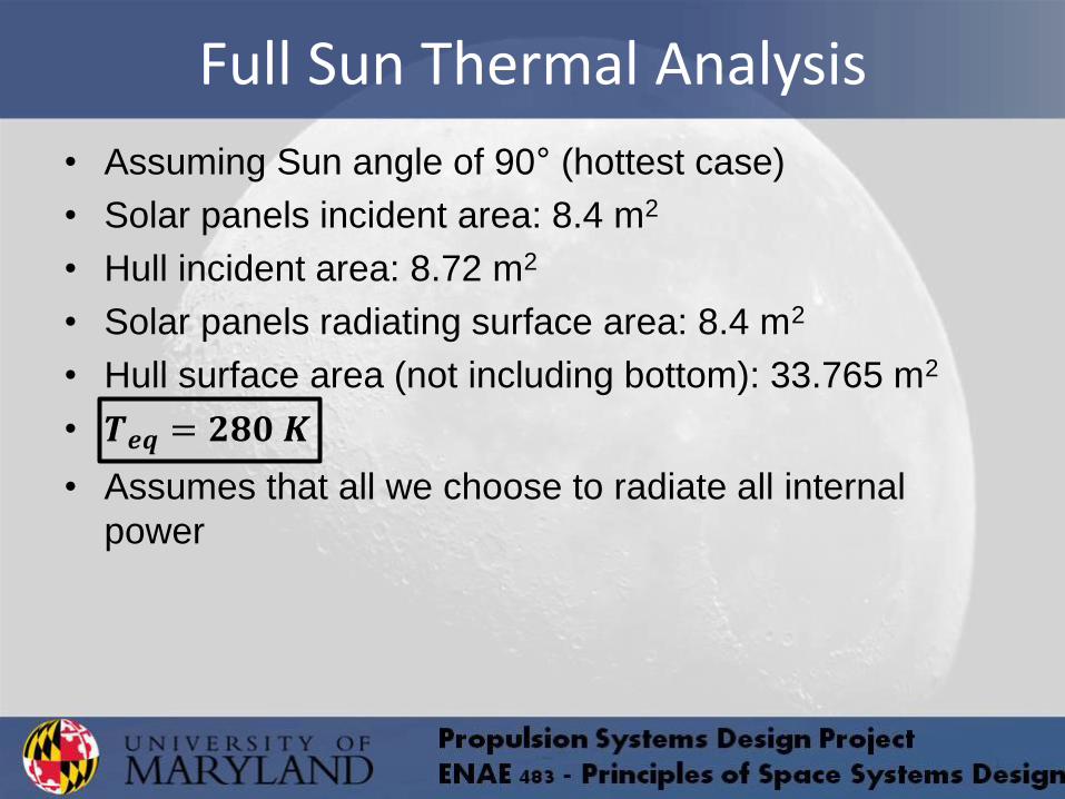
Full Sun Thermal Analysis
• Assuming Sun angle of 90° (hottest case)
• Solar panels incident area: 8.4 m2
• Hull incident area: 8.72 m2
• Solar panels radiating surface area: 8.4 m2
• Hull surface area (not including bottom): 33.765 m2
• 𝑻𝒆𝒒 = 𝟐𝟖𝟎 𝑲
• Assumes that all we choose to radiate all internal
power
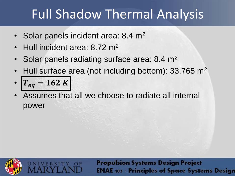
Full Shadow Thermal Analysis
• Solar panels incident area: 8.4 m2
• Hull incident area: 8.72 m2
• Solar panels radiating surface area: 8.4 m2
• Hull surface area (not including bottom): 33.765 m2
• 𝑻𝒆𝒒 = 𝟏𝟔𝟐 𝑲
• Assumes that all we choose to radiate all internal
power
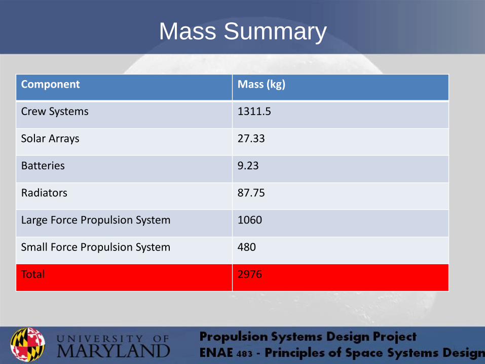
Mass Summary
Component Mass (kg)
Crew Systems 1311.5
Solar Arrays 27.33
Batteries 9.23
Radiators 87.75
Large Force Propulsion System 1060
Small Force Propulsion System 480
Total 2976

References
• “Absorptivity & Emissivity table 1 plus others.” Solar Mirror. Web. 08 Nov. 2012. http://solarmirror.com/.
• "High Accuracy Calculation for Life or Science." High Accuracy Calculation for Life or Science. Web. 08 Nov. 2012. http://keisan.casio.com/.
• Pennell, S., and J. Deignan. "Computing the Projected Area of a Cone." SIAM Review 31.2 (1989): 299. Print.
• Soto, Laura T., and Leopold Summerer. POWER TO SURVIVE THE LUNAR NIGHT: AN SPS APPLICATION? Proc. of 59th International Astronautical Congress,. Vol. IAC-08-C.3.1.2.