pr 150 / pr 170 - bivita
TRANSCRIPT

PR 150 / PR 170
Downloads
SANOTECHNIK.ITVia Pistelli 19, 92024 - Canicattì (AG), Italia P.IVA: 02649080849Tel: 0922 1807908Email: [email protected] PR 150 / PR 170

Lista Componenti – Packing list
Deutsch English Magyar Czech Română Slovensko Hrvatski Slovensky Turkey
1 15 ViteST3.5*11
Screw ST3.5*11
Csavarok ST3.5*11
šrouby ST3.5*11
Şuruburi ST3.5*11
Vijaki ST3.5*11
Vijci ST3.5*11
Skrutky ST3.5*11
Vida ST3.5*11
2 1 Tettuccio Top cover Tető střecha Capac Zgornji del Gornji dio Horná časť Tavan
3 1 Ventilatore Ventilator Ventillátor ventilátor Ventilator Ventilator Ventilator Ventilátor Vantilatör
4 1 Soffione Doccia Head
shower Fejzuhany sprcha hlavy
Cap dispersor
dus
naglavni tuš
tuš iznad glave
Hlava sprchy
Tepe Duşu
5 1 Luce superiore Top light Világítás osvětlení Iluminare Luč Svjetlo Svetlo Tepe Işığı
6 1 Amplificatore loudspeaker Hangszóró reproduktor difuzor zvočnik zvučnik reproduktor Hoparlör
7 1 Guida superiore curva
Bend rail top
Felső vezetősín
Vodící oblouk horní
Profil ghidaj sus
Vodilo - zgoraj
Horná vodiacia
lišta
Üst Profil
8 1 Parete posteriore Back wall Hátfal zadní stěna Partea din spate
hrbtni panel
zadnja panel
Zadná stena
Arka Cam Panel
9 22 Vite ST3.5*13
Screw ST3.5*13
Csavarok ST3.5*13
šrouby ST3.5*13
Şuruburi ST3.5*13
Vijaki ST3.5*13
Vijci ST3.5*13
Skrutky ST3.5*13
Vida ST3.5*13
10 1 Mensola Shelf Piperepolc polička Poliţă Polička Polica Odkladací priestor
Raf
11 1 Parete posteriore Back wall Hátfal zadní stěna Partea din spate
hrbtni panel
zadnja panel
Zadná stena
Masaj Paneli
12 1 Pannello di controllo Control panel Kezelőpanel kontrolní
panel Panou de comanda
Kontrolni elem.
Kontrolni elem.
Kontrolný element
Kontrol Paneli
Packing1 22,35,29
Packing2 11,17,18,22,27,28
,29,32
Packing3 8,13,15,16
Packing4
1,2,3,4,5,6,7, 9,10, 12, 14,
19,20,21, 23,24,25,26,
30,31, 33,34,36,37

13 1 Parete posteriore Back wall Hátfal zadní stěna Partea din spate
hrbtni panel
zadnja panel
Zadná stena
Arka Cam Panel
14 8 Vite ST3.8*2.5
Screw ST3.8*2.55
Csavarok ST3.8*2.5
šrouby ST3.8*2.5
Şuruburi ST3.8*2.5
Vijaki ST3.8*2.5
Vijci ST3.8*2.5
Skrutky ST3.8*2.5
Vida ST3.8*2.55
15 4 Guida curva corta Bend rails short
Vezetősín, rövid
Vodící profil krátky
Profile ghidaj scurte
Vodila - kratka Vodiace
lišty krátke
Yan Profil
16 2 Parete laterale Side wall Oldalfal boční stěna Perete lateral
stranski panel
panel sa strane
Bočná stena
Yan Cam
17 2 Profilo di Alluminio Aluminium rail Alu profil ukončovací
profil skla Profil
aluminiu ALU-profil ALU-profil Tesnenie Arka Dikey Profil
18 4 Profili fissi (interni)
Fixed profiles (inside)
Belső profil Venkovní profil
Profil fix (interior)
Fiksni profili (znotraj)
Vnútorné profily
Ön Dikey Profil
19 1 Porta asciugamani Towel rail Törölközőtartó držák ručníku
Suport prosop
Držalo brisač
Nosač ručnika
Držiak na uterák
Havlu Barı
20 12 Vite M4*20 Screw M4*20
Csavarok M4*20
šrouby M4*20
Şuruburi M4*20
Vijaki M4x20
Vijci M4x20
Skrutky M4*20
Vida M4*20
21 1 Vasca da bagno bathtub Kád sprchová vanička
Cadita dus tuš kad tuš kada Sprchová
vanička Küvet
22 2 Profili fissi fix profiles Sarokprofil Rohový profil
Profil colt Kotni profili Rohové
profily Ön dikey
Profil
23 1 Doccetta Hand shower Kézi zuhany ruční
sprcha Dispersor Tuš ročka Tuš ručica Ručná sprcha
El Duşu
24 1 Barra scorrevole Sliding bar Zuhanysín Sprchová tyč
Suport dus
Vodilo za prho
volilica za tuš
Tyč na sprchu
Kapı Camı
25 2 Soffione doccia Shower hose
Zuhany gégecső
sprchová hadice
Furtun dus tuš cev tuš cijev Sprchová
hadica El Duşu Hortumu
26 1 Massaggio piedi foot massage Lábmasszírozó masaz
nohou nasaj talpi Masaza stopal
Masaza stopala Masáž nôh Ayak
Masajı 27 1 Rubinetto Faucet Csaptelep armatura Baterie armatura miješalica Batéria Musluk
28 4 Getti Jets Fúvókák trysky Duze Šob Mlaznica Trysky Masaj Jetleri
29 2 Ante fisse Fix doors Fix üvegfal pevná část koutu Usa fixa Stekleni
fiksni panel
Stakleni fiksni panel
Sklenené pevné
dielcekútu
Sabit ön cam
30 2 Parete fissa curva
Fixglaspart Bend
Fix üvegfal, íves
Pevný díl ohnutý
Parte fixa de sticla
Fiksni stekleni del - upognjen
Pevný sklenený
diel, zahnutý
Sabit Cam Contası
31 4 T Dichtung "T" gasket "T"-tömítés "T" těsnění Cheder T T-tesnilo T-brtvilo "T" tesnenie
T conta
32 2 Profili frontali fissi
Front Fixed profiles Frontprofil Čelní profil Profil fata
fix Fiksni profili
- sprednjiČelné profily
Ön Sabit Profil
33 2 Maniglie Handles Fogantyú úchytky Mânere Ročaji Rukohvati Úchytky Kapı Kulbu
34 8 Rotelle scorrevoli Sliding wheel Görgők pojezdy Role Koleščki Kotačići Kolieska Kapı
Tekerleği
35 2 Ante scorrevoli Sliding doors Tolóajtó posuvné dveře
Usi culisante Drsna vrata Klizna
vrata Posuvné
dvere Kapı Camı
36 4 Vite ST4*10 Screw ST4*10
Csavarok ST4*10
šrouby ST4*10
Şuruburi ST4*10
Vijaki ST4*10
Vijci ST4*10
Skrutky ST4*10
Vida ST4*10
37 1 Guide curve inferiori
Bend rails bottom Alsó vezetősín
Vodící oblouk spodní
Profil ghidaj jos
Vodilo - spodaj
Spodná vodiaca
lišta
Yatay Profil

ITALIANO - ITALIANO - ITALIANO - ITALIANO - ITALIANO - ITALIANO
GUIDA
MONTAGGIO E ISTRUZIONI D'USO
1) Introduzione
2) Montaggio
3) Dati tecnici
4) Installazione Elettrica
5) Installazione Idraulica
6) Diagramma generatore di vapore
7) Clausole
8) Pannello remoto
ATTENZIONE! ATTENZIONE! ATTENZIONE!
Il cliente deve garantire che la cabina doccia sia montata in modo tale che vi sia spazio libero per lavori di
revisione e riparazione.
La cabina doccia a vapore deve essere montata in una stanza sul cui pavimento vi sia un sifone!
I tubi in acciaio flessibili inclusi sono solo oggetti di prova|
E' necessario controllare i requisiti tecnici, come la pressione dell'acqua di 1-3 bar, calcare massimo 8 dh etc.

Prefazione
1. Prima di aprire la confezione, si prega di controllare che la confezione non abbia eventuali danni. Prima dieffettuare il montaggio, è necessario verificare l'integrità completa delle parti.2. Per l'installazione sono necessari i seguenti strumenti: trapano, cacciavite a stella, livella, metro a nastro, matita,chiavi regolabili universali.3. Il lato liscio del vetro deve essere sempre rivolto verso l'interno.4. L'installazione può essere effettuata solo da ditte autorizzate (ad esempio idraulico), per garantire il diritto digaranzia. (Vedere le istruzioni per il collegamento di acqua ed elettricità).5. E' necessario che tutte le cuciture siano sigillate.6. E 'necessario rispettare rigorosamente le regole di installazione fissato dalla società idriche locali e le disposizioni dilegge in vigore.ATTENZIONE: Non consentito l'uso di tubazioni rigide tra la doccia e la fornitura di acquaIl collegamento deve essere flessibile in modo da essere possibile in qualsiasi momento per manutenzione oassistenza. La temperatura dell'acqua che fluisce attraverso i componenti cabina non deve superare i 60 ° C.
DATI TECNICI Connessione 220 V / 50 Hz, Controllo 12 V Pressione dell'acqua 1 – 3 bar, max. 60° WW, max. 9° DH
1. INSTALLAZIONE IDRAULICAI collegamenti idraulici devono essere flessibili, permettendo la libera manutenzione in qualsiasi momento.La temperatura dell'acqua che scorre nei rubinetti e nelle docce può essere di massimo 60° C.La pressione dell'acqua max 4 bar.E' necessario osservare tutti i requisiti di legge per l'installazione.
2. CONDUZIONE D' ACQ UA (in loco) ∅ 40mm (∅ 50 mm)E' necessario che vi sia un flessibile, estensibile intermedio (50 cm) tra il collegamento del sifone e gli scarichi devono essereinstallati in modo che sia possibile effettuare la manutenzione nel lato posteriore.
3. INSTALLAZIONE ELETTRONICA:La connessione elettronica può essere eseguita solo da una compagnia elettrica con licenza ufficiale.I requisiti si installazione delle aziende di servizi pubblici locali devono essere rigorosamente rispettate.Il cavo (cavo rivestito H05VV-f3G2, 5 YMM-J 3X2, 5 mm² fino a 3500 watts) deve avere un interruttore differenziale (almeno 25 A V~ Auslösenennstrom I = 0.03 A 230/400) e un interruttore IN = 16 A o 25 A U-tipo. Allo stesso modo, questo circuito deve esserespento con un interruttore onnipolare con apertura dei contatti di almeno 3 mm.Lo schema è allegato.
4. CLAUSOLE:Per la maggior parte dei nostri prodotti la garanzia è di 2 anni, e copre i difetti di conformità ai sensi degli art. 128 e ss. Del Decreto Legislativo del 6 settembre 2005 n. 206. Affinché la garanzia sia valida, il prodotto deve essere stato utilizzato o correttamente, nel rispetto della sua destinazione d’uso e di quanto previsto nella documentazione allegata. La garanzia è riservata al consumatore privato e può essere esercitata solo se si è in possesso degli originali documenti di spedizione. Le riparazioni o sostituzioni dei prodotti o loro parti avvengono nella nostra sede; Sono esenti da garanzia le parti soggette ad usura. Alcuni prodotti destinati ad usi estremi hanno una garanzia ridotta: in tal caso si troverà esplicito avviso nella descrizione. I termini di garanzia decadono nei casi di:
- Incuria, abuso, uso maldestro, uso ed installazione errati o impropri;- Su prodotti non correttamente installati da personale specializzato; preghiamo quindi i Clienti di conservare la fattura di installazione;- Scariche elettriche e tensioni non conformi alle caratteristiche del prodotto, descritte nel manuale o nelle targhette di riferimento;- Modifiche del prodotto non autorizzate e/o non conformi alle specifiche del Costruttore;- Da uso di accessori e materiale di consumo non originale;- Da utilizzo di prodotti non certificati e non originali;- per manomissione dei prodotti o, comunque per rimozione del sigillo di garanzia;- guasti o difetti causati da parti estranee e/o derivanti dal conflitto con componenti aggiuntivi;- Per qualsiasi intervento effettuato dai clienti sui prodotti in garanzia non autorizzato preventivamente;- Qualora i materiali pervengano alla nostra sede senza preventiva segnalazione;- Per tutto il materiale pervenuto alla nostra sede senza corredo (manuali, cavetteria, driver, etc.) e imballo originale.
Per ricevere assistenza durante il periodo di garanzia è necessario inviare una email a : [email protected] , indicando la natura e le caratteristiche del difetto riscontrato e allegando tutta la documentazione e ddi acquisto (ddt,foto, ecc.). I prodotti dovranno pervenire esclusivamente negli imballi originali: imballaggi malfatti o impropri fanno decadere le condizioni di garanzia. Ogni prodotto dovrà pervenire completo del corredo originale (cavetteria,, manualistica, software etc.), e degli originali documenti di trasporto. La mancanza del corredo comporta la non completezza del prodotto, pertanto non permetterà il cambio del prodotto stesso qualora si ritenesse non riparabile e quindi sostituibile. Per limitare danni alla confezione originale raccomandiamo, quando possibile, di inserirla in una seconda scatola; va evitata in tutti i casi l’ apposizione di etichette o nastri adesivi direttamente sulla confezione originale del prodotto.Ogni arrivo della merce non preventivamente autorizzato sarà tassativamente non accettato e respinto. Nel caso di prodotti installati, SANOTECHNIK ITALIA SRL fornirà la parte di ricambio necessaria per ripristinare il bene; la sostituzione del pezzo o l'uscita del tecnico è a carico del cliente. In caso di difetto di conformità, SANOTECHNIK ITALIA SRL provvede, senza spese per il Cliente, eccetto le spese di trasporto, al ripristino della conformità del prodotto mediante riparazione/sostituzione o alla riduzione del prezzo alla risoluzione.
– 1 –
ITALIANO - ITALIANO - ITALIANO - ITALIANO - ITALIANO - ITALIANO

ITALIANO - ITALIANO - ITALIANO - ITALIANO - ITALIANO - ITALIANO
5. TERMINI DI USO E CURA:
La completa doccia deve sempre essere mantenuta pulita per evitare contaminazione batterica. Utilizzare solo prodotti per la pulizia non aggressivi. Mantenere pulita la doccia con un panno morbido.
Montaggio
1. Installare il tubo di scarico.
2. Connetti il pannello di mezzo (11) al pannello posteriore (8 e 13) con le viti M4*25 e posiziona le parti sul piatto doccia.
3. Avvita le rotelle (7,37) su entrambi i lati del profilo Parete (22), posiziona il bordo in alluminio (7,37,22) nel piatto doccia efissa il bordo con le pareti laterali (16).Usa le viti ST3.5*13.Fissa il pannello posteriore (8,13) sul piatto doccia e connettilo alle pareti laterali (16) con le viti M4*25.
4. Posiziona le ante fisse di vetro (29) nel bordo di alluminio (7,37,22). Fissa le parti in vetro fissando il profilo frontale (32)al bordo in alluminio (7,30) con le viti.Usa le viti ST3.5*13.Posiziona la guarnizione a "T" (31) tra le parti in vetro fisse e le guide in alluminio.
5. Monta le rotelle scorrevoli (34) solo sulla parte superiore di entrambe le ante (35) e appendile alle guide scorrevoli.Quindi monta le rotelle scorrevoli nel lato inferiore delle ante in vetro. Posiziona la striscia magnetica e la strisciaimpermeabile di plastica su entrambe le ante di vetro.
6. Monta le maniglie (33) alle ante, la barra doccia, la doccetta, il sifone, il massaggiatore per piedi, la mensola e ilvaporizzatore sui pannelli posteriori (8,13).
7. Fissa il tettuccio (2) con i pannelli laterali (8,13), usando le viti M4*25. Monta la componente elettronica.
8. Testa per verificare che tutte le viti sono ben fissate e le ante si chiudono bene. Se la chiusura non è precisa, mettere delsilicone.
– 2 –

ITALIANO - ITALIANO - ITALIANO - ITALIANO - ITALIANO - ITALIANO
– 3 –

ITALIANO - ITALIANO - ITALIANO - ITALIANO - ITALIANO - ITALIANO
– 4 –

ITALIANO - ITALIANO - ITALIANO - ITALIANO - ITALIANO - ITALIANO
– 5 –

ITALIANO - ITALIANO - ITALIANO - ITALIANO - ITALIANO - ITALIANO
– 6 –

ITALIANO - ITALIANO - ITALIANO - ITALIANO - ITALIANO - ITALIANO
– 7 –

ITALIANO - ITALIANO - ITALIANO - ITALIANO - ITALIANO - ITALIANO
– 8 –

ITALIANO - ITALIANO - ITALIANO - ITALIANO - ITALIANO - ITALIANO
– 9 –

ITALIANO - ITALIANO - ITALIANO - ITALIANO - ITALIANO - ITALIANO
– 10 –
Connessioni Idrauliche
Doccetta
Soffione
Acqua Fredda
Acqua Calda
Massaggio Piedi
Ingresso Acqua
Getti

ITALIANO - ITALIANO - ITALIANO - ITALIANO - ITALIANO - ITALIANO
Connessioni Elettroniche
– 11 –

ITALIANO - ITALIANO - ITALIANO - ITALIANO - ITALIANO - ITALIANO
Telecomando Radio
Guida di sicurezza :
• Il pannello del computer deve essere installato da un operatore specializzato.• I parametri elettrici del prodotto devono essere conformi alle relative norme nazionali.• La tensione di alimentazione è AC 230 +/- 10%• Si prega di spegnere il controllo dopo ogni utilizzo. Scollegarlo quando non viene utilizzato per un
lungo tempo.
NOTA: La garanzia del controller decade in caso di danni risultanti dalla modifica del circuito o dalla connessione di apparecchiature elettriche senza previo permesso del produttore.
– 12–

ENGLISH – ENGLISH – ENGLISH – ENGLISH – ENGLISH – ENGLISH -
DIRECTORY:
MOUNTING AND USING INSTRUCTIONS page
1) Introduction ...................................................................2
2) Mounting .......................................................................2-9
3) Technical data ...................................................... 10
4) Electrical installation ....................................................... 10
5) Water installation............................................................ 10
6) Diagram steam generator ............................................ 11
7) Appointments clauses ................................................... 12
8) Remote panel .............................................................. 13-14
IMPORTANT ! IMPORTANT ! IMPORTANT ! IMPORTANT !
The client have to guarantee, that the complete shower cabin is mount in such way, that every time it is free
amenably to make overhauls or repair work. The steam shower cabin have to mount in a room what is lapses and
there must be a floor siphon in this room!
The included flexible steel hoses are only test objects!!
It must be checked before the technical prerequisites, such as water pressure 1-3 bar, lime max 8 dh etc.

ENGLISH – ENGLISH – ENGLISH – ENGLISH – ENGLISH – ENGLISH -
Introduction 1. Before you unpack the shower, you check the packaging for damage. Later complaints will not be recognized. Beforeassembling, all parts for damage and completeness are checked. In case of problems contact the seller and us time andyou will get a satisfactory answer.2. For installation the following tools is required: drill, screwdriver, spirit level, tape measure, pen, ring wrench.3. With embossed glass or frosted glass is to be noted is that the smooth side mounted to the inside.4. It is all factory-fitted shower room for testing purposes, connected, tested and packaged.5. Place the shower tray and using adjustable feet, so set that no water remains in the shower tray.IMPORTANT: stress test. Subsequent complaints are excluded.6. The assembly should be conducted only by authoritarian specialist firms (eg plumber), otherwise it will void thewarranty. (See also note for connection of water and electricity)7. It is observed the enclosed assembly instructions and all parts must be additionally sealed against each other withsanitary silicone (silicone) Leak test. In addition, need to be checked all the screws, hose clamps, etc. to its strength andtightness. It might have come loose due to the transport something.
INSTALLATION - MAINTENANCE - WARRANTY - SECURITY - TERMS OF USE
TECHNICAL DATA: Conection 220 V / 50 Hz, Control 12 V Water pressure 1 – 3 bar, max. 60° WW, max. 9° DH
1. Water installation:(On site) The connection may be performed by an officially licensed installation companies. The installation requirements of the local water company and the provisions of DIN 1988 are to be observed strictly. For the sewer connection is to provide for a trap. Attention: No rigid pipe connections between Fertigduschen and water - risk of breakage! This line must be secured by a Rohrunterbrecher type A2 according to DIN 1988. The connections must be flexible, allowing an unobstructed maintenance or service at any time. The water temperature of the water, which flows through the faucets and showers can be max. C..°60 The water pressure can be max. 4 bar. In general, observed for the water installation with all legal requirements
2. WATER CONDUCT: (On site) ∅ 40mm (∅ 50mm)There must be a flexible, extensible intermediate (50 cm) between the siphon and sewer connection be installed so that a pushback for maintenance or service is possible.
3. Electrical installation (On site) The electronic connection may be performed only by an officially licensed electrical company.The installation requirements of local utility companies and the provisions of DIN 57100 orVDE 0100 Part 701 must be strictly observed. The cable (sheathed cable H05VV-f3G2, 5 YMM-J 3x2, 5 mm ² up to 3500 watts)must have an earth leakage circuit breaker (at least 25 A 230/400 V ~ Auslösenennstrom I = 0.03 A are held) and a circuit breakerIN = 16 A or 25 A U-type (in Austria: IN = 13 A 16 or A C-Type will be protected). Similarly, this circuit must be switched off with anall-pole switch with at least 3 mm contact gap. (must be in the protected area 3) are the equipotential line (at least 4 mm ² copper)is connected to the appropriate agencies. Schematic is attached.
4. Appointments clauses:The warranty is required by law during the period from the date of purchase. This must be the basis of a cash card or a payment document - the name of the dealer and the date of sale aufscheinen -. Customer Services for Sales Territory Austria: It will only be reported in writing customer service jobs, as performed, for example, guaranteed rates, or accepted if this is proven by a written message with proof of purchase (cash receipt) ... the service there. The warranty covers repairs and replacement of components of the device, which must be recognized by the company SANOTECHNIK. The intervention fee is payable by the customer, which is payable directly to the customer service. But not on installation and removal, and all other costs, these are excluded. Operational noises do not justify a complaint. Excluded from the warranty, defective parts, whose failure to negligence, improper use, use-wear, improper installation, maintenance by unlicensed personnel, are due damage in transit, such as backups, for example, decorative elements, etc. By poor compliance with the instructions of the manufacturers of any direct or indirect liability declines to persons or property. Indirect damage, w. for example, consequential damages due to lack of use or removal of any manufacturer is not liable. For repairs after the warranty period, the parts replaced, in work and travel expenses - according to the applicable rates set - into account. The current rates of fees, you can ask your customer service.
– 1 –

ENGLISH – ENGLISH – ENGLISH – ENGLISH – ENGLISH – ENGLISH -
4. TERMS OF USE and CARE:
The complete shower always be kept clean to avoid bacterial contamination. Use only mild, organic cleaning products. Always clean with a soft cloth.
When calcium deposits (blockages) of head or hand shower with rubber studs, you can easily be cleaned with a finger. In head-or hand-held showers without rubber nubs from time to time you should clean with a needle (calcified pierce holes)
! ATTENTION! !ATTENTION ! ATTENTION !The complete shower is fixed before mounting again carefully for any visible damage check, including the assembled components. The same applies to the surface of the Fertigduschkabine, furthermore conducted must necessarily be a trial run.
Mounting ATTENTION!! Please note that the pre-drilled holes do not necessarily have to have something with the assembly of the parts. The existing holes are introduced by production. All parts are screwed according to the following installation instructions with each other, with the holes must be drilled for this purpose by means of steel drill bit. Where appropriate, can fit in the existing wells be shared..
Mounting 1. Set scales-quite geared up the bathtub (21), Install the drain pipe.2. Connect the middle panel (11) with the back wall (8 and 13) , with the screws M4*25 and put the parts on the shower tray.3. Screw the bend rails (7,37 ) on bouth sides on the Wall profile (22), put the aluminium border (7,37,22) onto the shower
tray and fix the border with the side walls (16).Juse the screws ST3.5*13.Fix the back panels (8,13) on the shower tray and connect them with the side walls (16) with the screws M4*25.
4. Put the fix glass parts (29) into the aluminium border (7,37,22). You fix the glass parts by fixing the front profile (32) withthe aluminium border (7,30) with screws.Juse the screws ST3.5*13.Put the ’’T” gasket (31) between fix glass parts and aluminium rails.
5. Mount the sliding wheels (34) only on the upper side on bouth glassdoors (35) and hang them into the bend rails.After this you can mount the sliding wheels on the lower side of the glassdoors. Put the magnetic strip and the anti-waterplastic strip on bouth glassdoors.
6. Mount the handels (33) on the doors, the shower bar, hand shower, the shower hose, the foot massage, the shelve andthe steam outlet on the back panels (8,13).
7. Fix the roof (2) with the sidepanels (8,13) , juse the screws M4*25. Mount the electronic .Connect the electronic correct.8. Test if you have fix the srews well and if the door will be close .Make a close control .If it is leaky. pls give silicone
between.
– 2 –

ENGLISH – ENGLISH – ENGLISH – ENGLISH – ENGLISH – ENGLISH -
– 3 –

ENGLISH – ENGLISH – ENGLISH – ENGLISH – ENGLISH – ENGLISH -
– 4 –

ENGLISH – ENGLISH – ENGLISH – ENGLISH – ENGLISH – ENGLISH -
– 5 –

ENGLISH – ENGLISH – ENGLISH – ENGLISH – ENGLISH – ENGLISH -
– 6 –

ENGLISH – ENGLISH – ENGLISH – ENGLISH – ENGLISH – ENGLISH -
– 7 –

ENGLISH – ENGLISH – ENGLISH – ENGLISH – ENGLISH – ENGLISH -
– 8 –

ENGLISH – ENGLISH – ENGLISH – ENGLISH – ENGLISH – ENGLISH -
– 9 –

ENGLISH – ENGLISH – ENGLISH – ENGLISH – ENGLISH – ENGLISH -
– 10 –
Water connections
Jets
Water inlet
Footmassage
Hot water
Cold water
Handshower
Topshower

ENGLISH – ENGLISH – ENGLISH – ENGLISH – ENGLISH – ENGLISH -
Electrical connections
– 11 –
ENGLISH – ENGLISH – ENGLISH – ENGLISH – ENGLISH – ENGLISH -
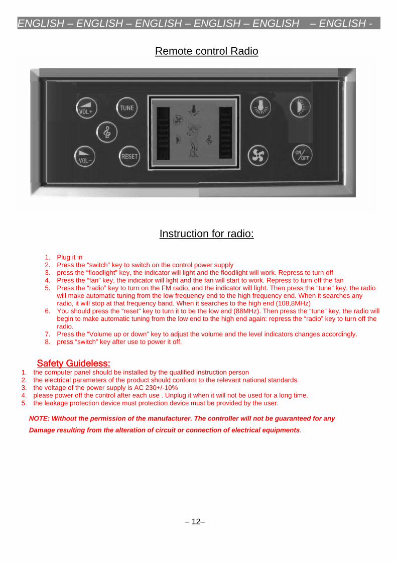
Remote control Radio
Instruction for radio:
1. Plug it in2. Press the “switch” key to switch on the control power supply3. press the “floodlight” key, the indicator will light and the floodlight will work. Repress to turn off4. Press the “fan” key, the indicator will light and the fan will start to work. Repress to turn off the fan5. Press the “radio” key to turn on the FM radio, and the indicator will light. Then press the “tune” key, the radio
will make automatic tuning from the low frequency end to the high frequency end. When it searches anyradio, it will stop at that frequency band. When it searches to the high end (108,8MHz)
6. You should press the “reset” key to turn it to be the low end (88MHz). Then press the “tune” key, the radio willbegin to make automatic tuning from the low end to the high end again: repress the “radio” key to turn off theradio.
7. Press the “Volume up or down” key to adjust the volume and the level indicators changes accordingly.8. press “switch” key after use to power it off.
Safety Guideless: 1. the computer panel should be installed by the qualified instruction person2. the electrical parameters of the product should conform to the relevant national standards.3. the voltage of the power supply is AC 230+/-10%4. please power off the control after each use . Unplug it when it will not be used for a long time.5. the leakage protection device must protection device must be provided by the user.
NOTE: Without the permission of the manufacturer. The controller will not be guaranteed for any
Damage resulting from the alteration of circuit or connection of electrical equipments.
– 12–