practical approaches for solving lost circulation …
TRANSCRIPT
i
PRACTICAL APPROACHES FOR SOLVING LOST CIRCULATION
PROBLEMS WHILE DRILLING
A THESIS
by
HARRISON TETTEH-FIAGBOR
Submitted to the African University of Science and Technology
in partial fulfillment of the requirements for the degree of
MASTER OF SCIENCE
December, 2011
Major Subject: Petroleum Engineering

ii
PRACTICAL APPROACHES FOR SOLVING LOST CIRCULATION
PROBLEMS WHILE DRILLING
RECOMMENDED BY:
……………………………………………………………….
(Prof. Samuel Osisanya, Chair of Advisory Committee)
………………………………………………………………..
(Prof. Godwin Chukwu, Member of Advisory Committee)
…………………………………………………………………
(Dr. Alpheus Igbokoyi, Member of Advisory Committee)
APPROVED BY:
………………………………………………………………….
(Prof. Charles Chidume, Academic Officer, AUST, Abuja)
Date: ………………………………………………………………….
iii
ABSTRACT
As the demand for petroleum resources increases, drilling of oil and gas wells are often
carried out in challenging and hostile environments. Among the top ten drilling challenges facing
the oil and gas industry today is the problem of lost circulation. Major progress has been made to
understand this problem and how to combat it. However, most of the products and guidelines
available for combating lost circulation are often biased towards advertisement for a particular
service company. The purpose of this study is to develop practical guidelines that are general and
not biased towards a particular service company product and which will also serve as a quick
reference guide for lost circulation prevention and control at the well-site for drilling personnel.

iv
DEDICATION
This work is dedicated to God for being my strength through all my challenging moments
in Graduate School. To my mum, for giving me a different meaning to life. Finally, to my
beloved sisters, Hilda and Rhodaline, for their encouragement and support.

v
AKNOWLEDGEMENTS
I would like to express my appreciation to Prof. Samuel Osisanya, my supervisor, for his
immense contribution to the success of this work. When I approached him to work with him, he
wholeheartedly accepted me despite his busy schedules; Dr. Sam, am very grateful for your time.
I would also like to thank Prof. Godwin Chukwu (Head of Department) and Dr. Alpheus
Igbokoyi for accepting to serve as members of my Graduate Advisory Committee and also for
their inputs to the success of this work.
Special appreciation also goes to Mr. Kunle Opawale for his effort and time. Kunle, your
contributions and proofreading of this work has yielded positive results.
Finally, I would like to thank my friends and fellow students of African University of
Science and Technology (AUST) for being there for me throughout my life in Graduate School.
Without you, life would have been so boring here.
vi
TABLE OF CONTENTS
PAGE
ABSTRACT iii
DEDICATION iv
ACKNOWLEDGEMNENTS v
TABLE OF CONTENTS vi
LIST OF FIGURES viii
LIST OF TABLES ix
CHAPTER
1 FORMULATION OF PROBLEM 1
1.1 Introduction 1
1.2 Literature Review 2
1.3 Research Objectives 5
1.4 Research Methodology 5
1.5 Organization of Thesis 5
2 FUNDAMENTALS OF LOST CIRCULATION CONTROL 6
2.1 Lost Circulation Materials (LCMs) Selection 6
2.1.1 Conventional LCMs 7
2.1.2 High Fluid Loss Squeezes 7
2.1.3 Gunk Slurries 7
2.1.4 Precipitated Chemical Slurries 8
2.1.5 Chemically Activated Cross-linked Pills 8
2.1.6 Cement Slurries 8
2.1.7 Dilatant Slurries 8
2.2 Borehole Stability Analysis 9
2.2.1 Fractures and Fracture Identification 9
2.2.2 Mechanics of Fracturing 15
2.3 Management of Equivalent Circulation Density 17
vii
CHAPTER PAGE
3 REVIEW OF LOST CIRCULATION CONTROL METHODS 22
3.1 Using Lost Circulation Materials 22
3.2 Wellbore Strengthening 24
3.3 Using Drilling Techniques/Procedures 27
3.3.1 Aerated Mud Drilling 27
3.3.2 Floating Mudcap Method 28
3.3.3 Drilling Blind 28
3.4 Using Advances in Drilling Technology 28
4 PRACTICAL GUIDELINES TO COMBAT LOST CIRCULATION
WHILE DRILLING 31
4.1 General Guidelines 31
4.1.1 Locating the Loss Zone 32
4.1.2 Estimating Pressure in the Loss Zone 35
4.1.3 How to Detect Cross-flows in the Loss Zone 37
4.2 Seepage Losses 37
4.2.1 Ignore the Problem and Drill Ahead 37
4.2.2 Pull up and Wait 38
4.2.3 Pretreat the Active Mud System with LCM 38
4.3 Partial Losses 43
4.4 Severe and Total Losses 45
4.4.1 Blind Drilling 45
5 SUMMARY, CONCLUSIONS, AND RECOMMENDATIONS 47
5.1 Summary 47
5.2 Conclusions 47
5.3 Recommendations 48
NOMENCLATURE 49
REFERENCES 51
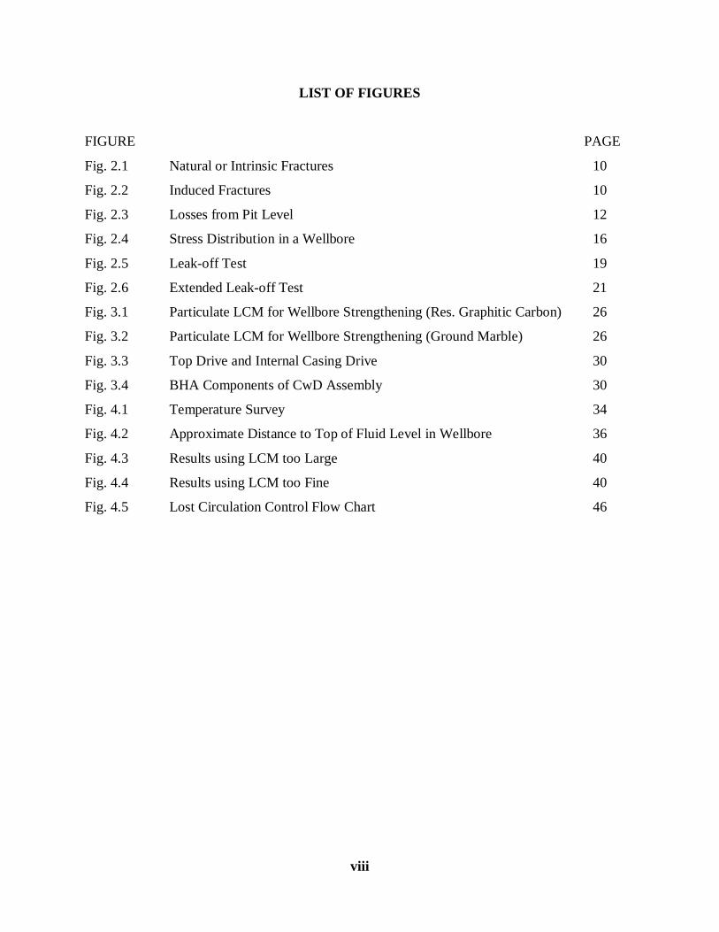
viii
LIST OF FIGURES
FIGURE PAGE
Fig. 2.1 Natural or Intrinsic Fractures 10
Fig. 2.2 Induced Fractures 10
Fig. 2.3 Losses from Pit Level 12
Fig. 2.4 Stress Distribution in a Wellbore 16
Fig. 2.5 Leak-off Test 19
Fig. 2.6 Extended Leak-off Test 21
Fig. 3.1 Particulate LCM for Wellbore Strengthening (Res. Graphitic Carbon) 26
Fig. 3.2 Particulate LCM for Wellbore Strengthening (Ground Marble) 26
Fig. 3.3 Top Drive and Internal Casing Drive 30
Fig. 3.4 BHA Components of CwD Assembly 30
Fig. 4.1 Temperature Survey 34
Fig. 4.2 Approximate Distance to Top of Fluid Level in Wellbore 36
Fig. 4.3 Results using LCM too Large 40
Fig. 4.4 Results using LCM too Fine 40
Fig. 4.5 Lost Circulation Control Flow Chart 46
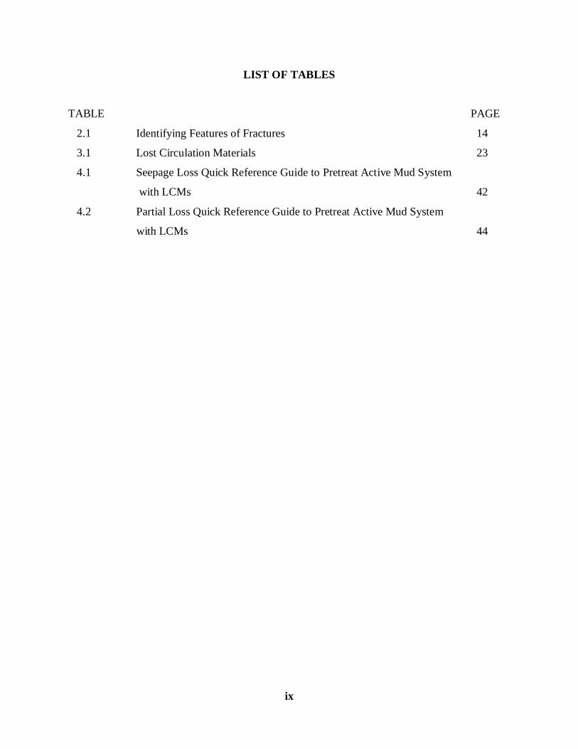
ix
LIST OF TABLES
TABLE PAGE
2.1 Identifying Features of Fractures 14
3.1 Lost Circulation Materials 23
4.1 Seepage Loss Quick Reference Guide to Pretreat Active Mud System
with LCMs 42
4.2 Partial Loss Quick Reference Guide to Pretreat Active Mud System
with LCMs 44
CHAPTER 1
FORMULATION OF PROBLEM
1.1 INTRODUCTION
Lost circulation is a common drilling problem especially in highly permeable formations,
depleted reservoirs, and fractured or cavernous formations. The range of lost circulation problems
begin in the shallow, unconsolidated formations and extend into the well-consolidated formations
that are fractured by the hydrostatic head imposed by the drilling mud (Moore, 1986). It can then be
defined as the reduced or total absence of fluid flow up the formation-casing or casing-tubing
annulus when fluid is pumped down the drill pipe or casing. The industry spends millions of dollars
every year to combat lost circulation and its associated detrimental effects such as loss of rig time,
stuck pipe, blow-outs, and less frequently, the abandonment of expensive wells. Two conditions are
both necessary for lost circulation to occur down hole: 1) the pressure in the well bore must exceed
the pore pressure and 2) there must be a flow pathway for the losses to occur (Osisanya, 2011). Sub-
surface pathways that cause, or lead to, lost circulation can be broadly classified as follows:
Induced or created fractures (fast tripping or underground blow-outs)
Cavernous formations (crevices and channels)
Unconsolidated or highly permeable formations
Natural fractures present in the rock formations (including non-sealing faults)
The rate of losses is indicative of the lost pathways and can also give the treatment method
to be used to combat the losses. The severity of lost circulation can be grouped into the following
categories (Abbas et al. 2004):
Seepage losses: up to 10 bbl/hr lost while circulating
Partial losses: 10 – 500 bbl/hr lost while circulating
Severe losses: more than 500 bbl/hr lost while circulating
Total losses: no fluid comes out of the annulus
Circulation may be lost even when fluid densities are within the customary safety-margin;
less dense than the fracture density of the formation. Stopping circulation losses before they get out
of control is crucial for safe and economically rewarding operations (Abbas et al. 2004). According
to Ivan and Bruton (2003), “Deepwater drilling has brought loss circulation control to a more
critical level as it involves narrow pore-pressure/fracture-gradient windows, cold drilling fluid
temperatures, high equivalent circulating densities (ECDs), high cost-per-barrel of synthetic-based
fluids (SBM) and a high cost for rig time/non-productive time (NPT).” The reduction of the fracture
pressure gradient in the deeper water is mainly due to the low stress regime as a result of the
1
reduction in the overburden pressure gradient. Also, drilling through sub-salt zones poses a
challenge to the operator because of the problem of lost circulation encountered in these zones.
These wells have shear zones above and below the salt formations and also narrow margins
between the pore and fracture pressure and hence these wells tend to register severe losses in
circulation.
1.2 LITERATURE REVIEW
Lost circulation is a broad subject and several studies and measures have been introduced in
the industry to combat it. For example, Moore, (1986) noted that in shallow, unconsolidated
formations where the drilling fluid may flow easily into the formation, the most common method
used to combat lost circulation is to thicken the mud. This may be done in fresh water muds by
adding flocculating agents such as lime or cement. He also stated that in areas such as below surface
casing in normal-pressure formations where natural fractures are common, the most common
method used to combat lost circulation is to drill without fluid returns to the surface. The purpose is
to remove the generated cuttings from the hole and deposit them at the lost circulation zone.
However, this practice requires large volumes of water and close supervision as there is the
possibility of encountering high drill-string torque and drag.
Current research on lost circulation has been focused on the use of Lost Circulation
Materials (LCMs), especially chemical formulations which have been proven to be more effective.
Hamburger et al. (1983) of Exxon Production Research Company developed a Shear-thickening
Fluid (STF) which was tested successfully in 10 different wells that experienced severe lost
circulation. A STF is a multi-component system composed of water-swellable material (usually
clay) dispersed in an oil-external emulsion. The emulsion consists of liquid oil, an oil-soluble
surfactant, and aqueous-phase droplets containing dissolved polymer. At the low shear rates
encountered while it is being pumped down the drill pipe, the fluid is a low-viscosity, pumpable
liquid. Yet as it passes through the drill-bit nozzles, the resulting high shear rates cause the fluid to
thicken irreversibly into a high strength viscous paste.
Nayberg, (1987) conducted laboratory tests that compared the performance of conventional
LCMs (granules, flakes and fibers) with a new high-performance material which is composed of
thermoset rubber in controlling mud loss in simulated fractured formations using both water-based
and oil-based muds. From field applications, he found out that the use of thermoset rubber was very
effective in controlling severe mud losses in fractured formations. Also, Gockel et al. (1987) of
Agri-Systems of Texas Inc. conducted a research on the use of Expanded Aggregates (EAs) as
opposed to the use of convention LCMs. AEs are vitrified mineral-based materials that are made
from several types of clay-bearing soils. The results obtained from six different field applications
2
showed that AEs were efficient in solving several lost return problems as compared to conventional
LCMs because they have high compressive strengths, do not change mud rheological properties,
and have rapid lost return resolution properties. Vidick et al. (1988) also conducted a research into
the use of internally activated silicate solution. Laboratory tests indicated that this solution has a
low viscosity initially but after some time which depends on its design and temperature, its
viscosity increases rapidly to form a gel. This gel is coherent, strong, and does not produce free
water as a function of time. A high pressure experimental set up was used to plug cores of different
permeabilities and different saturation fluids. They found out that the gel formed by this solution
could withstand differential pressures greater than 1500 psi per foot of plugged formation.
Other researchers have worked on the use of specially formulated squeeze materials
(reactive pills) as LCMs. Sweatman et al. (1997) studied the use of lost circulation material squeeze
systems (LCMSS). These LCM squeeze systems were applied in wells after conventional
materials/methods failed and they successfully cured the losses. Data from field trials indicated that
losses were cured in wells having temperatures ranging from below 80 to over 325 oF, highly
vugular or channel zones, weak zones that are easily fractured by oil-based and water-based drilling
muds and other extreme conditions. Bruton et al. (2001) conducted studies on Chemically Activated
Cross-linked Pills (CACP). These pills are activated by cross-linking agents, time and borehole
temperature. When set, they produce a substance described as rubbery, spongy, and ductile. The
setting time is fully controllable by using either a retarder or an activator based upon the thief
formation or bottom hole temperature. However, laboratory tests and field trials suggest that these
pills are not biologically or chemically degradable and hence they must be used with caution near
pay zones.
Sweatman et al. (1999) also studied the use of mud-reactive-chemical-squeeze (MRCS)
system and process, in especially subsalt zones, to cure losses. They observed that in 1996, during a
problematic subsalt drilling operation in the Gulf of Mexico, the MRCS system and process
successfully halted severe mud losses that, combined with a high pressure water influx, equalled
1200 bbl/hr. They noted that one reason this technology is successful in the subsalt zone is that the
solidification of the mud and MRCS system downhole is accelerated before the mixture enters the
thief zone. In addition, this system does not bridge the hole above the thief zone. Depending on the
mud type, the solidification reaction is designed to occur after 10 seconds or after 5 to 7 minutes.
Suyan et al. (2007) researched the use of a novel sealant system consisting of an elastomer
combined with cross-linking polymers, activator and bridging agents which provided a quick and a
reliable control of loss returns. Initial low viscosity of this sealant allows it to be placed in the loss
zone and then gel activated near the wellbore to set and form a stiff, rubbery gel stick with
formation sediments to prevent further losses. The composition can be engineered to produce
3
durable cross-linked polymeric gel across a wide range of densities (8.6 – 14 ppg) and temperatures
(45 – 120 0C). Addition of accelerators or retarders during mixing controls setting time and
eliminates premature setting inside the drill string while pumping. Another novel work was done by
Darugar et al. (2011) where they researched into the use of single-sack fibrous pills as LCMs. This
one-sack product does not require activators, retarders, set time calculations or temperature
activation. It has been specifically designed for rapid mixing and pumping with minimal equipment.
Laboratory studies have demonstrated the ability of the fibrous pill slurries to rapidly de-water/de-
oil and form a sealing plug on both ceramic filter discs and slotted metal discs. Testing also shows
that the product forms a sealing plug in depleted sand formations. The product is suitable, and has
also been tested with a wide range of fluids including freshwater, brine, and base oils.
The use of cement as LCM has also become a common practice while drilling and many
researches have investigated its use. Cement could provide a permanent cure for the problem and is
irreversible in many cases. Therefore, it is generally applied to non-producing zones (surface
drilling), in which mud loss is extremely severe, as a quick but permanent solution (Fidan et al.
2004). Vinson et al. (1992) did a study on the use of acid removable cement to stop losses in
producing zones. This cement has been formulated to have moderate thixotropic properties, but
with sufficiently small particle size and low rheologies to penetrate near-wellbore fractures and
voids. The synthetic cement is readily mixed using conventional oilfield cementing equipment. It
has been field tested in producing zones where losses occurred with success. Samsuri and Phuong,
(2002) also designed a special cement formulation which is composed of 9 % local bentonite, 2 %
calcium chloride, and 0.5 % sugar cane fiber with adequate shear bonding strength and formation
permeability reduction of about 10 %. From their experimental work, they came out with the
following: cement slurry suitable for controlling lost circulation must have light density, minimum
free water and fluid loss content, compressive and bonding strengths must be enough to support
casing, and shorter thickening time.
A recent work by Metcalf et al. (2011) in which they investigated the successful application of
a new environmentally-friendly natural polymer to control lost returns during drilling and primary
cementing operations in the Permian Basin of West Texas is also worth noting. This polymer
consists of 30 pounds per barrel of conventional LCMs, a natural polymer, and silicate particles.
They presented instances where this material was used to cure partial to total losses in more than
100 wells during drilling and primary cementing operations after other loss return control
materials/methods have failed.
In summary, successful control or treatment of lost circulation while drilling depends on
several factors such as borehole temperature, pressure, depth, and size of the thief zone.
The purpose of this study is to evaluate new methods being used in combating lost circulation
4
in the drilling industry and develop practical guidelines that will serve as a reference material for
lost circulation control at the well-site for drilling personnel.
1.3 RESEARCH OBJECTIVES
The objectives of this study are as follows:
To review lost circulation control methods that have been applied in the drilling industry till date.
To provide the successes and the failures of the methods presented above in field applications.
To develop practical guidelines that will serve as a reference material for lost circulation control
at the well-site for drilling personnel.
1.4 RESEARCH METHODOLOGY
The objectives of this study will be achieved through the following methods:
Read various technical journals, papers and textbooks that talk on the subject of lost circulation
control over the years in the drilling industry.
Summarize these technical materials based on the various lost circulation control methods used
over time, their success stories, and their failures in various field applications.
Develop practical guidelines based on the above methods.
1.5 ORGANIZATION OF THESIS
This thesis is organized into five chapters. Chapter one focuses on formulation of the
problem. Chapter two addresses the theoretical background to lost circulation control. Chapter three
focuses on the review of lost circulation control materials/methods that have been applied in the
drilling industry till date and their successes and failures in field applications. Chapter four involves
the development of practical guidelines to solve lost circulation problems during drilling operations.
Chapter five addresses summary, conclusions, and recommendations of the thesis.
5

CHAPTER 2
FUNDAMENTALS OF LOST CIRCULATION CONTROL
A lot of effort has been done to understand the mechanics of lost circulation control. Lost
circulation control during well construction is more than just selecting the right lost circulation
material (LCM) but requires a complete engineered approach (Whitfill, 2008). Some of the
approaches involve borehole stability analysis, equivalent circulating density (ECD) modelling,
leak-off flow-path geometry considerations, drilling fluid and LCM selection to help minimize
effects on ECD, on-site monitoring using annular pressure while drilling (APWD), connection
flow monitoring techniques, and timely application of LCM and treatments. This chapter sheds
light on the physics and chemistry of some of the lost circulation control approaches.
2.1 LOST CIRCULATION MATERIALS (LCMs) SELECTION
LCMs are needed to stop fluid losses in order to drill ahead in most drilling operations.
An LCM should react, block fractures, and form a bridge to provide a seal in a timely manner.
The seal could be temporary or even permanent. Permanent seals are used to block thief zones in
non-producing intervals while temporary seals are used to block loss zones in pay intervals
(Fidan et al. 2004). Previous studies have demonstrated that some products work better than
others as lost circulation materials (Sanders et al. 2010). LCMs are categorized into common
groups along their physical and chemical characteristics. These groups are as follows
(Onyekwere, 2002):
Conventional Lost Circulation Materials; (fibers, flakes, and granules)
High Fluid Loss Squeezes; (diatomaceous earth or clay blends)
Gunk Slurries; (diesel oil bentonite)
Precipitated Chemical Slurries; (silicate and latex)
Resin-coated Sand
Cross-linked Polymer Slurries
Cements
Barite Plugs
Dilatant Slurries
6
2.1.1 Conventional LCMs
These LCMs can be classified as granular (ground walnut shells, pecan shells, almond
shells, plastic, and calcium carbonate), flakes (ground mica, plastic laminate, cellophane, and
polyethylene plastic chips), fibers (rice hulls, peanut hulls, wood, cane etc.) or a mixture of the
three. The granular LCMs form two types of bridges; one at the formation face and one within
the formation matrix. The latter sealing is preferred because it forms a more permanent bridge
within the formation such that pipe movements in the wellbore cannot dislodge the granular
particles. The effectiveness of granular LCMs depends on their particle size distribution, with
larger particles first forming a bridge across or within the void and smaller particles bridging the
openings between larger ones. Fibrous materials are best suited for controlling losses in porous
and highly permeable formations because they form a mat-like bridge over the pore openings.
The mat reduces the size of the openings to the formation, permitting the colloidal particles in
the mud to rapidly deposit a filter cake. Flake LCMs are also designed to form a mat on the
formation face, which also provides the best results as fibrous materials when used to treat losses
in porous and highly permeable formations. Blends of granular, flakes, and fibrous materials are
used in solving actual field problems (Pilehvari and Nyshadham, 2002).
2.1.2 High Fluid Loss Squeezes
These LCMs lose water quickly and deposit a thick cake of residual solids in the loss
zone. This method is particularly useful for preventing the extension of natural or induced
fractures, as the deposited solids prevent the transmission of pressure to the tip of the fractures.
The two main high fluid loss pills are: 1) DiaSeal M (diatomaceous earth) and 2)
Attapulgite/Calcium Carbonate (Onyekwere, 2002).
2.1.3 Gunk Slurries
The gunk slurries consist of two or more fluids which upon making contact with the
wellbore or the loss zone form a viscous plug which seals the zone. For partial losses, better
results are achieved by using Mud-Diesel-Oil-Bentonite (M-DOB) plugs. When this mixture
contacts water or water-based mud, a mass with high gel strength is formed. The DOB mixture is
pumped down the drill string while the mud is pumped down the annulus. M-DOB plugs have
several disadvantages (Pilehvari and Nyshadham, 2002):
They break down with time.
They are difficult to apply in long open hole intervals.
7

When losses are severe, it is impossible to achieve reliable pumping rate down the annulus;
therefore the degree of mixing cannot be controlled.
No compressive strength is developed.
There are, however, other gunk slurries that can be used with oil-based muds. For example,
Reverse-Diesel-Oil-Bentonite (R-DOB) is used for oil-based muds.
2.1.4 Precipitated Chemical Slurries
Both silicate solutions and commercial latex additives used for cementing can be made to
precipitate and used to plug loss zones when pumped in combination with calcium chloride. The
general ideal is to pump a calcium chloride pill followed by the silicate of latex slurry. When
these two slurries mix in the open hole, hopefully adjacent to the loss zone, they form a viscous
plug which can slow and seal many loss zones (Onyekwere, 2002).
2.1.5 Chemically Activated Cross-linked Pills (CACP)
Cross-linking is the linking of two independent polymer chains by a grouping (cross-
linking agents) that spans or links two chains. (Bruton et al. 2001). The advantage of these pills
is that they can be used to stop losses in water, oil or synthetic-based drilling muds. However,
their main limitation is that they are not biologically or chemically degradable in the wellbore
and hence they must be used with caution near pay zones.
2.1.6 Cement Slurries
Special cement formulations like magnesium-based cements and thixotropic cements are
more common (Onyekwere, 2002). Portland cements are also being used as LCMs only after
other techniques have proven unsuccessful, or if experience has shown it to be the method of
choice (Suyan et al. 2007). Portland cement compositions have particle size distributions in the
30 to 100 micron range; which, for the most part, should not penetrate the permeability matrix
near producing zones. Formation fractures can be created by rock stress which can accept whole
fluid during the cement placement process and lead to formation damage. However, using
cement recipes that combine an acid-soluble additive have proven to be viable alternatives to
reduce formation damage near productive zones (Fuller et al. 2010).
2.1.7 Dilatant Slurries
These LCMs are composed of specifically sized solids and polymers that are both water
soluble and insoluble (Onyekwere, 2002). An example is a Shear-thickening Fluid (STF) which
was developed by Exxon Production Research Company in 1983 (Hamburger et al. 1983). The
8
ability of these types of fluids to thicken irreversibly when they pass through the high-shear
zones in the drill bit make them suitable for stopping losses in any loss zone.
In summary, the theories and observations raised from years of experience fighting lost
circulation can be boiled down to five pertinent points (Bruton et al. 2001):
A lost circulation material should be equally effective in sealing unconsolidated formations
and fractures or vugs in hard formations.
It should form an effective seal under both low and high differential pressure conditions.
Final plug shear strength should be high enough to support fluid column, but low enough to
ensure removal by washing or jetting (low side-track risk).
The plugging seal has to withstand both negative (swab) and positive (surge) pressures
applied during drilling, drill pipe trips, and casing runs.
It should have workable/controllable set time and should be functional in oil, synthetic or
water based mud systems.
2.2 BOREHOLE STABILITY ANALYSIS
To effectively prevent and cure losses resulting from borehole stability issues, it is
important to understand the fundamental principles of this process.
2.2.1 Fractures and Fracture Identification
Lost circulation in fractured formations is one of the biggest drilling problems. Drilling
fluid losses to a formation can be through a fracture which has been induced through drilling
operations or a pre-existing natural fracture. If pre-existing, the fracture may be permanently
open in which case losses to the formation may occur at mud pressures only in excess of the
formation pressure. Induced fractures occur when the mud weight, required for well control and
to maintain a stable wellbore, exceeds the fracture resistance pressure of the formation (Majidi et
al. 2011). Identification of the type of fracture responsible for the losses is an important step in
combating the lost returns problem. Figures 2.1 and 2.2 are examples of natural and induced
fractures respectively.
9

Fig. 2.1 – Natural or Intrinsic Fractures (After Howard and Scott, 1951).
Fig 2.2 – Induced Fractures (After Howard and Scott, 1951).
10
Acoustic, electrical, and optical wellbore images provide means of detecting and
distinguishing natural fractures from induced fractures. The direct measurement of mud loss flow
rates and the downhole annular pressure while drilling (APWD) can also be used as an indication
of a fracture as well as the type of fracture (Majidi et al 2011). High resolution flow-meters can
accurately measure the rate of fluid flow into and out of the wellbore. The characteristic response
of the rate of losses can be used to interpret the fracture characteristics. A useful technique for
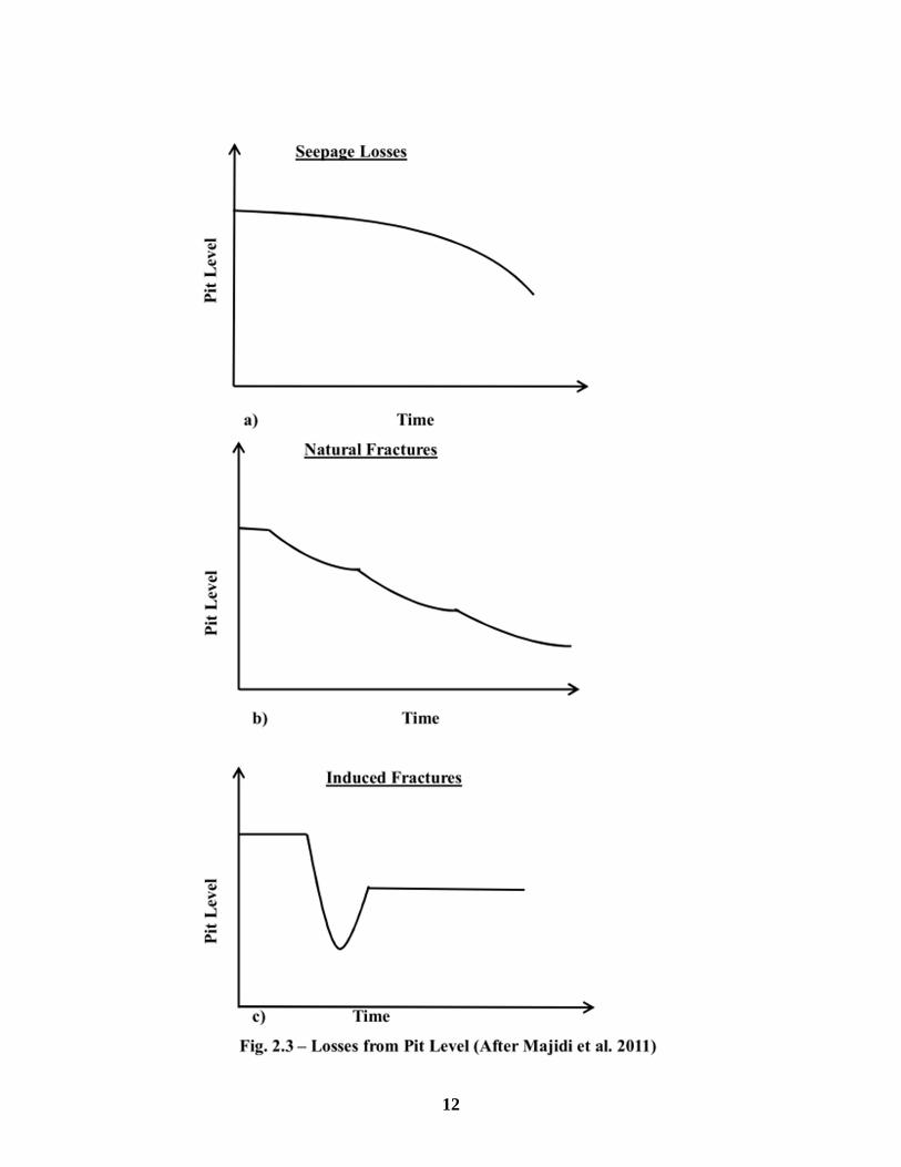
identifying the type of lost circulating zone is the utilization of plot of variation of mud pit levels.
Figure 2.3 shows a qualitative response of mud losses in terms of the mud pit level changes with
time.
11
12

Losses through pores are initially slow and gradually increase whereas losses through
natural fractures are rapid initially and then they decline with time. It is important to note that
fractures are not the only cause of mud losses during drilling operations and caution must be
exercised when evaluation the causes of mud losses. The following causes of fluctuating mud-
tank levels during drilling have been provided by Dyke et al. (1995):
Downhole losses through matrix permeability
Downhole losses into induced and natural fractures
Volume change owing to temperature and pressure effects
Surfaces mud losses
Hole collapse and enlargement
Change in bottom hole lithology
Table 2.1 summarizes some important identification features used to distinguish between
natural and induced fractures.
13

Table 2.1 - Identifying Features of Fractures (After Howard and Scott, 1951).
Natural Fractures Induced Fractures
May occur in any type of formation. May occur in any type of rock but would be expected
in formations with characteristically weak planes
such as shale.
Loss is evidenced by gradual lowering of mud
in pits. If drilling is continued and more
fractures are exposed, complete loss of returns
may be experienced.
Loss is usually sudden and accompanied by complete
loss of returns. Conditions are conducive to the
forming of induced fractures when mud weight
exceeds 10.5 ppg.
Loss may follow any sudden surge in pressure.
When lost circulation occurs and adjacent wells have
not experienced lost circulation, induced fractures
should be suspected.
14

2.2.2 Mechanics of Fracturing
Induced fractures normally occur at the weakest part of formations. The requirements for
forming fractures are pressure and surfaces upon which the pressure may act so that the resultant
forces are of sufficient magnitude and are exerted in such a manner to part the formations
(Howard and Scott, 1951). Depending upon depth, the fractures created will either be vertical or
horizontal. If the depth is around 2,500 feet or less, horizontal pancake fractures are usually
produced because the vertical stress (overburden) is lower than the horizontal stresses. At depths
greater than 3,500 feet, vertical fractures are created because the overburden is higher than the
horizontal stresses (Ramirez et al. 2005). Figure 2.4 shows a typical stress distribution in a
wellbore.
15

Fig. 2.4 – Stress Distribution in a wellbore (After Kumar et al. 2011)
16
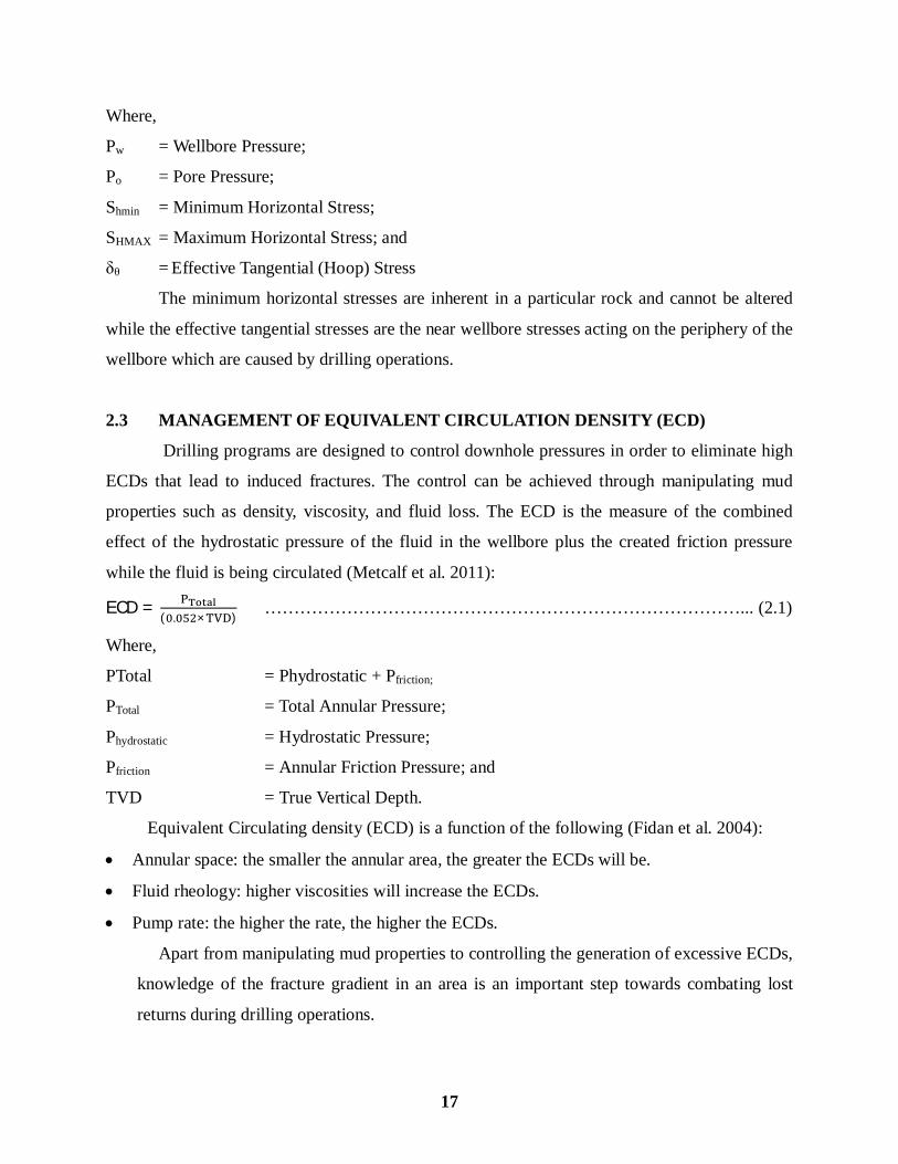
Where,
Pw = Wellbore Pressure;
Po = Pore Pressure;
Shmin = Minimum Horizontal Stress;
SHMAX = Maximum Horizontal Stress; and
= Effective Tangential (Hoop) Stress
The minimum horizontal stresses are inherent in a particular rock and cannot be altered
while the effective tangential stresses are the near wellbore stresses acting on the periphery of the
wellbore which are caused by drilling operations.
2.3 MANAGEMENT OF EQUIVALENT CIRCULATION DENSITY (ECD)
Drilling programs are designed to control downhole pressures in order to eliminate high
ECDs that lead to induced fractures. The control can be achieved through manipulating mud
properties such as density, viscosity, and fluid loss. The ECD is the measure of the combined
effect of the hydrostatic pressure of the fluid in the wellbore plus the created friction pressure
while the fluid is being circulated (Metcalf et al. 2011):
ECD =( . × )
………………………………………………………………………... (2.1)
Where,
PTotal = Phydrostatic + Pfriction;
PTotal = Total Annular Pressure;
Phydrostatic = Hydrostatic Pressure;
Pfriction = Annular Friction Pressure; and
TVD = True Vertical Depth.
Equivalent Circulating density (ECD) is a function of the following (Fidan et al. 2004):
Annular space: the smaller the annular area, the greater the ECDs will be.
Fluid rheology: higher viscosities will increase the ECDs.
Pump rate: the higher the rate, the higher the ECDs.
Apart from manipulating mud properties to controlling the generation of excessive ECDs,
knowledge of the fracture gradient in an area is an important step towards combating lost
returns during drilling operations.
17

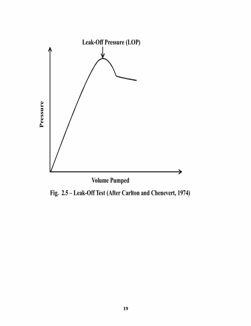
The fracture gradient is determined through a leak-off test (LOT). The LOT provides a
safe method to determine the amount of pressure (equivalent mud weight) that a wellbore
will withstand without fracturing and losing returns (Carlton and Chenevert, 1974). In this
test, the borehole immediately behind the casing shoe is pressurized until fluid begins to leak
into the formation which means that a fracture has been created. The leak-off pressure (LOP)
is the first deviation from a linear pressure-volume curve as shown in Figure 2.5.
18
19

If the local fracture gradient is sufficiently known at a certain casing shoe depth, a simpler
formation integrity test (FIT) is often performed instead. FIT is performed by pressurizing the
formation to a predetermined pressure without fracturing the formation; this is used to test
cement integrity. Combination of LOTs is used to generate local and regional depth trends which
are used to predict fracture gradients in other wells. However, the following limitations are
associated with using LOTs to generate a fracture gradient curve (Okland et al. 2002):
Individual tests may be difficult to interpret when no clear or unique deflection/deviation
point exists.
Test data is often recorded manually at a coarse sampling rate, disallowing raw data scrutiny.
Some bias towards higher interpretations may even be introduced by the drilling team’s
eagerness to drill ahead.
Leak-Off Pressures (LOPs) from a group of neighbouring wells are often scattered, giving
considerable room for subjective interpretation of local trend.
An extended leak-off test (XLOT) which has striking similarities with the early stages of a
lost circulation event can be used to overcome the limitations associated with LOT (Okland et al.
2002). XLOT was designed mainly to measure the minimum in-situ stress (i.e. the fracture
closure pressure, FCT). However, it can be used to capture additional fracture events that will
serve as a valuable tool in designing drilling programs to combat lost circulation. Some of the
additional events captured by XLOT are:
FIP: Fracture Initiation Pressure
FRP: Fracture Re-opening Pressure
FCP: Fracture Closure Pressure
ISIP: Initial Shut-in Pressure
FPP: Fracture Propagation Pressure
The decision to perform an XLOT at the casing shoe should take into account both the cost
of breaking the near-well barrier and the benefit of knowing what stress and FPP lies behind that
barrier. The near-well barrier is the volume of rock whose stress state is affected by the presence
of the borehole, usually 1-2 hole diameters into the formation.
Figure 2.6 shows an example of an XLOT from the Norne field in offshore Norway.
20
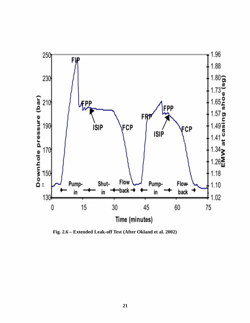
Fig. 2.6 – Extended Leak-off Test (After Okland et al. 2002)
21
CHAPTER 3
REVIEW OF LOST CIRCULATION CONTROL METHODS/TECHNIQUES
Lost circulation solutions may be applied before or after the occurrence of the problem
(Wang et al. 2009). The solutions are therefore grouped into preventive and remedial
respectively. This chapter highlights some of the lost circulation control methods/techniques that
are used in the petroleum industry.
3.1 USING LOST CIRCULATION MATERIALS (LCMs)
A wide range of bridging or plugging materials is available for reducing lost circulation
or restoring circulation while drilling or cementing a well (Nayberg and Petty, 1986). The choice
of LCM to use in a given case depends on cost and availability in a given drilling area (Pilehvari
and Nyshadham, 2002). LCMs are designed to accomplish two goals (Jiao and Sharma, 1996):
To bridge across the face of fractures and vugs that already exist.
To prevent the growth of any fractures that may be induced while drilling.
Lost circulation materials can be broadly classified into the following groups (Suyan et al.
2007; Pilehvari and Nyshadham, 2002):
Granular: these LCMs form bridges at the formation face and within the formation matrix,
thus providing an effective seal which depends on the particle size distribution (PSD).
Fibrous: these groups of LCMs are used in drilling muds to lessen mud loss in fractures and
vugular formations.
Flakes: flaky types of LCMs are used to plug and bridge many types of porous formations to
stop the mud loss or to establish an effective seal over many permeable formations.
Mixtures: these are combinations of granular, flaky and fibrous materials that will penetrate
fractures, vugs, or extremely permeable formations and seal them off effectively.
Encapsulated fluid-absorbing particles: these are materials that are highly absorbent and form
spongy mass in contact with water.
Detailed classification of LCMs has been covered in chapter 2 of this thesis. From a
review of various literatures on lost circulation, it can be inferred that a combination of LCMs
rather than one is effective in combating losses. Table 3.1 provides some commonly used LCMs.
22

Table 3.1 – Lost Circulation Materials (After White, 1956).
TYPE MATERIAL
FIBROUS
Raw cotton, Bagasse, Flax shive, Wood
fiber, Bark fiber, Textile fiber, Mineral fiber,
Leather, Glass fiber, Peat moss, Feathers,
Beet pulp.
GRANULAR
Perlite, Coarse bentonite, Ground plastic, Nut
shells, Nut hulls, Ground tires, Asphalt,
Wood, Coke.
FLAKE
Cellophane, Cork, Mica, Corn cobs, Cotton-
seed hulls, Vermiculite.
MIXTURE
Film, fiber and sawdust;
Textile fiber and sawdust;
Cellulose fiber and sawdust;
Perlite and coarse bentonite.
23
3.2 WELLBORE STRENGTHENING
Conventional lost circulation materials (LCMs), including pills, squeezes, pretreatments
and drilling techniques often reach their limit in effectiveness and become unsuccessful when
drilling deeper hole sections where some formations are depleted, structurally weak, or naturally
fractured and faulted (Wang et al. 2005). To address these issues, new lost circulation solutions
such as wellbore strengthening has evolved. The process of propping and plugging fractures with
LCMs induced in the formation is referred to as wellbore strengthening (Kumar et al. 2010).The
overall effect of using wellbore strengthening is to increase the fracture gradient of the
formation. This provides an opportunity to use higher mud weight windows for drilling,
especially, weaker and depleted formations. Wellbore strengthening methods, generally, rarely
target strengthening the rock matrix but are mostly applied to (van Oort et al. 2009):
Enhance the near-wellbore stress, thus raising the threshold for fracture re-opening and
growth.
Increase the formation’s resistance to fracture propagation.
However, there are chemical methods that enhance rock matrix strength in permeable and
depleted formations. There are a number of approaches to wellbore strengthening, one of which
is the stress cage approach (van Oort et al. 2009). This approach aims at creating an additional
hoop stress (a “stress cage”) in the near-wellbore region, adding to the already existing hoop
stress riser when a wellbore is created. Near-wellbore fractures of specific sizes are deliberated
created and packed with specially sized LCMs in a frac-and-pack type of operation. Because of
the presence of the packed LCMs, an additional tangential stress (hoop stress) is created in the
near-wellbore zone, which raises the threshold for fracturing and fracture propagation. The stress
cage approach can be applied while drilling into the weak zone to obtain the strengthening effect
instantaneously (Wang et al. 2009). An important step in this approach involves using log
analysis to identify fracture location and determine its geometry, especially its width, and then
determine a mixture of particulates materials that will seal the calculated fracture width (Song
and Rojas, 2006).
24
The key characteristics of the particulate materials that will affect their performance in
the wellbore strengthening process have been provided in order of descending importance
(Freidheim et al. 2008):
Particle size
Particle size distribution
Concentration
Shape (sheroidicity/aspect ratio)
Others (surface texture, compressive strength, bulk density, resiliency, etc.)
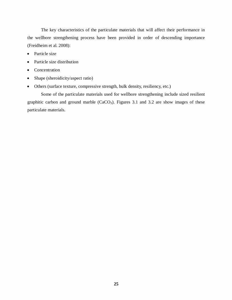
Some of the particulate materials used for wellbore strengthening include sized resilient
graphitic carbon and ground marble (CaCO3). Figures 3.1 and 3.2 are show images of these
particulate materials.
25
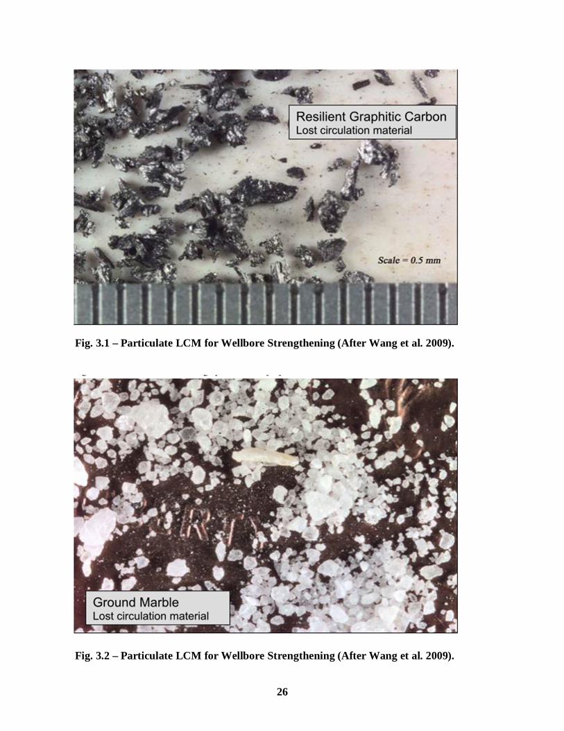
Fig. 3.1 – Particulate LCM for Wellbore Strengthening (After Wang et al. 2009).
Fig. 3.2 – Particulate LCM for Wellbore Strengthening (After Wang et al. 2009).
26
3.3 USING DRILLING TECHNIQUES/PROCEDURES
The drilling techniques/procedures described in the subsequent paragraphs may be used
to prevent or remedy lost circulation problems.
3.3.1 Aerated Mud Drilling
Aerated mud is defined as a fluid (in the form of mists and foams) consisting of liquid
(usually water), air, and drill cuttings (Guo and Rajtar, 1995). Aerated muds are low density
fluids that can be used to maintain a minimum overbalance while drilling probable loss zones
such as depleted formations that are competent and low-pressured. Aerated mud drilling is
recognized as having many advantages over conventional mud drilling; such as higher
penetration rate, less formation damage, minimized lost circulation, and lower drilling cost.
Foams are highly structured fluids of air bubbles contained in a continuous network of liquid
films. The structured nature of the fluid and the wide size distribution of the air bubbles means
that foams have the ability to bridge a wide range of pore sizes, and even small fractures.
However, foams have the following disadvantages (Reid and Santos, 2003):
Specialized equipment is required to generate them. This may be costly, and in offshore
locations, deck space may limit the use of foams.
Foams are compressible and so lose some or all of their structure (and hence bridging
properties) under downhole conditions. Downhole densities and rheology become difficult to
predict and control.
To address the limitations of foams, a new class of aerated fluids, known as aphrons, has
been developed. The aphron system is an at-balance technique that uses micro bubbles that are
non-coalescing and can be re-circulated (Redden et al. 2011). Aphrons are engineered to occur
within the drilling fluid without the need to inject air or gas. They exist as independent spheres
where a multiple layer film encapsulates a gas or air core. This film is the key to maintaining the
bubble strength that allows aphrons to function as bridging agents. A surfactant is used to
produce the surface tension to contain the aphron as it is being formed, build the multi-layer
bubble wall, and create interfacial tension that binds the aphrons into a network capable of
creating downhole bridges.
27
3.3.2 Floating Mudcap Method
A Floating mudcap is a column of drilling fluid floating on the annulus side of the
drillstring to hold back formation fluids/pressure. This method is used only as a final option
when massive and total lost circulation has occurred and all attempts to regain circulation have
failed. This is because the operation can be very expensive and hazardous. The floating mudcap
method involves pumping water down the drillstring to clean, cool, and lubricate the bit. Drilling
fluid is added on the annulus side and it is weighted to exert hydrostatic pressure on top of the
formation to keep the well under control. The drill water carries the cuttings into the loss zone
where it disappears into the formation. The density of the drilling fluid in the annulus must be
heavy enough to keep the well under control and must also be light enough to prevent any further
losses.
The floating mudcap method is hazardous and requires rigorous safety procedures and only
experienced crew to handle it. When the formation pressure equals the hydrostatic pressure of
the drilling fluid, the well is in equilibrium. The drill water will exert an additional pressure
against the fluid column which will force the drilling fluid back out the top of the column. This
reduces the hydrostatic pressure which forces formation fluids to migrate into the annulus. This
is a kick and needed to be handled (Redden et al. 2011).
3.3.3 Drilling Blind
When loss zones are too large and difficult to be filled and sealed by lost circulation
materials, the recommended approach is to drill blind until competent formations are
encountered , after which casing is set (Redden et al. 2011). When drilling blind, it is important
to maintain a pumping rate equal or greater than the pumping rate normally used to clean the
hole. Otherwise, there is a risk of sticking the drillstring. Therefore, adequate source of water is a
necessity when this technique is to be carried out efficiently (Canson, 1985).
3.4 USING ADVANCES IN DRILLING TECHNOLOGY
Developments in new drilling technology such as expandable tubulars and casing-while-
drilling (CwD) can serve as long term methods that will mitigate the costly effects of lost
circulation while drilling (Davison et al. 2004). Expandable tubulars permit a number of mud
weights to be used for different sections without losing hole size due to the telescoping effect of
casing.
28
Casing-while-drilling employs downhole and surface components to provide the ability to
use normal oilfield casing as the drillstring so that the well is simultaneously drilled and cased
(Tessari et al. 1999). The casing is rotated from the surface with a top drive. Drilling fluid is
circulated down the casing internal diameter (ID) and up the annulus between the casing the
wellbore. The objective of this technology is to reduce the non-productive time (NPT) and the
casing running times where partial and total fluid losses make conventional drilling practices
difficult and expensive (Gallardo et al. 2010). Two types of CwD exist: retrievable and non-
retrievable systems. The retrieval system uses a drillpipe or wireline to retrieve the bottom hole
assembly (BHA) assembly attached to the casing or liner. The non-retrievable system is designed
to leave the casing drill shoe (CDS) on bottom if the last section of the well is being drilled to
total depth (TD) or is to be drilled afterwards to continue with the following hole sections.
Figures 3.3 and 3.4 are pictures of part of the CwD assembly.
29

Fig. 3.3 – Top Drive and Internal Casing Drive (After Tessari et al. 2006).
Fig. 3.4 – BHA Components of CwD Assembly (After Gallardo et al. 2010).
30
CHAPTER 4
PRACTICAL GUIDELINES TO COMBAT LOST CIRCULATION WHILE DRILLING
4.1 GENERAL GUIDELINES
The drilling program must include contingency plans (additional casing strings, adequate
water source etc.) for known problems such as that associated with infill drilling and
unknown problems such as those encountered in wildcat drilling.
The following information is required about the loss zone before an effective treatment could
be achieved:
a) The location of the loss interval – preferably the top and bottom.
b) Estimate the pressure within the loss zone.
c) Estimate the size of the openings into the loss zone; use borehole electronic images.
d) Knowledge of whether or not there is cross-flow into the loss zone because of the reduced
pressure in the wellbore. Cross-flows into the loss zone can complicate the treatment process.
A quick economic evaluation should be made of how much investment would go into curing
the lost returns problem before a decision is made to case the zone off, or side-track the loss
interval or even abandon the project.
It is important to reduce human error, to a tolerable minimum, as a contributing factor to lost
circulation. The following drilling practices were identified as contributing to lost circulation:
Generation of excessive ECDs caused by high circulation rates (Prevention strategy: Use the
lowest circulation rate that will clean the hole adequately).
Failure to break circulation frequently while tripping (Prevention strategy: Break circulation
several times on the way into the hole and rotate the pipe; when on the bottom, break
circulation slowly, and raise the pipe while doing so).
High pipe running speeds (Prevention strategy: Run pipe slowly, and above all, do not ream
down rapidly with the pumps on).
Monitor downhole annular pressure and make sure that the ECD and equivalent static density
(ESD) always stay within the safe mud weight window during drilling, connection, and
tripping by optimizing mud weight and drilling operations.
It is advisable to include properly sized LCM in the drilling mud when drilling formations
that are prone to losses (depleted formations). This practice can help in preventing seepage
31

losses and also prevent induced fractures from propagating beyond their initiation stages.
Graphitic carbon and sized calcium carbonate have proven to be effective primary LCMs if
included in the drilling mud in the course of drilling through depleted and weak formations.
Avoid the use of coarse LCMs that require by-passing the solids control equipment as this
will result in fines build up in the mud and increase viscosity and ECD which may induce
more losses.
LCMs come in many different forms; each possesses a specific advantage such as cost,
availability and effect or lack of it on drilling fluid properties. However, the performance of a
LCM is based primarily on its concentration, particle size distribution (PSD), and shape.
Size LCMs to restrictions in Bottom Hole Assembly (BHA); consult the manufacturer or
Directional Drilling Services Company if necessary.
When circulations are lost temporally due to pressure surges induced while running casing or
because bottom hole pressures are exceeded while breaking circulation after a trip, it is
recommended to reduce the solids content or reduce the yield point (YP) value of the drilling
mud rather than using LCMs.
Overall well economics can influence whether to pre-treat the system with LCM or deal with
the problem when/if the problem occurs.
Get ready for well control situations when handling losses.
4.1.1 Locating the Loss Zone
Drilling through a low pressure, naturally fractured formation is normally signalled by a
sudden severe loss of returns which is accompanied by a notable increase in drilling torque and
relative drilling roughness. This signature is a reliable indication that the loss zone is at the
bottom when no previous incident of lost circulation had occurred (Canson, 1985). When drilling
through vugs, channels, and caverns, apart from the drilling conditions experienced in low
pressure naturally fractured formations, the drill-string can advance to a particular depth
unrestricted without taking any weight.
Since rock strength generally increases with depth, the location of an induced fracture is
closer to the previous casing shoe than total depth (Ramirez et al. 2005). To accurately locate the
loss zone, a temperature survey is employed. Circulation of drilling fluids will alter the static
geothermal gradient in a borehole because of the injection of cooler mud (Sweatman et al. 1997).
A base temperature log is run to establish the normal temperature gradient in the well
32

under static conditions. Then a volume of mud (equal to 1000 – 1500 feet of open hole) is
pumped into the hole from the surface and a second temperature log is run. The two logs are
compared to determine the location of the loss zone. A cooler gradient is observed on the
second log from the surface to the point of mud exit into the loss zone. However, below the
loss zone, higher temperature gradient should be observed on both logs. Figure 4.1 shows a
temperature survey used to locate a loss zone.
33

Fig. 4.1 Temperature Survey (After Canson, 1985).
34
Radioactive logs, noise logs, and mechanical devices (flowmeters) can also be used to
locate the loss zone (Canson, 1985). The above methods are useful when the loss zone is off the
bottom of the well. When the loss zone is at the bottom of the well, it is advisable to drill through
the loss interval until the top and bottom of the loss interval can be established.
4.1.2 Estimating Pressure in the Loss Zone
This information is especially useful when total loss of returns is experienced. Without
this information, the control of the flow of treatment material into the loss zone is left to trial and
error work, and as such the treatment might not be successful (Canson, 1985). To estimate this
pressure, knowledge of the static fluid level in the wellbore is a requirement. A number of
methods are available to estimate static fluid level in the well; echometer determinations as well
as counting pump strokes to fill the annulus are two of the methods used (Gray and Darley,
1980). Another method used is described below (Ferron et al. 2011):
A one inch diameter ball is formed with soft clay. A stopwatch is started when the ball
is released over the wellbore and stopped when the ball hits the static fluid level in the wellbore.
It is advisable that the ball does not hit the sides of the wellbore when it is released otherwise it
will take a longer time to hit the fluid level. From figure 4.2, tracing the time along the vertical
until it hits the curve, the distance to the top of the fluid level in the wellbore can be estimated.
From this estimated distance and knowing the depth of the loss zone, the pressure in the loss
zone can be estimated using a simple formula:
Ploss zone = Dstatic fluid column × MW × 0.052 ……………………………………………………...(4.1)
Where,
Ploss zone is the pressure in the loss zone (psi);
Dstatic fluid column is the static fluid column above the loss zone (feet); and
MW is the mud weight (lb/gal).
35
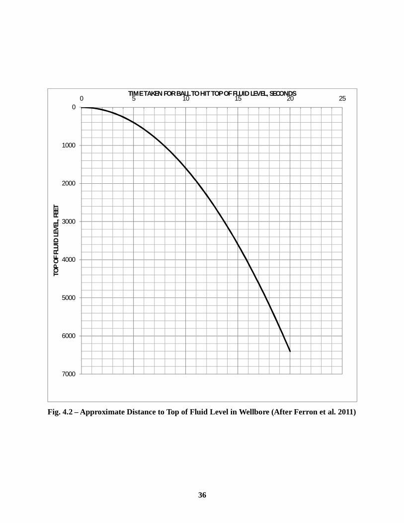
Fig. 4.2 – Approximate Distance to Top of Fluid Level in Wellbore (After Ferron et al. 2011)
0
1000
2000
3000
4000
5000
6000
7000
0 5 10 15 20 25
TOP
OF
FLU
ID L
EVEL
, FEE
T
TIME TAKEN FOR BALL TO HIT TOP OF FLUID LEVEL, SECONDS
36
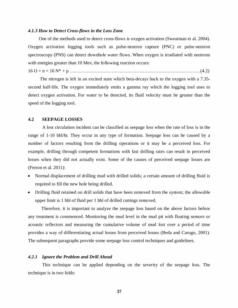
4.1.3 How to Detect Cross-flows in the Loss Zone
One of the methods used to detect cross-flows is oxygen activation (Sweatman et al. 2004).
Oxygen activation logging tools such as pulse-neutron capture (PNC) or pulse-neutron
spectroscopy (PNS) can detect downhole water flows. When oxygen is irradiated with neutrons
with energies greater than 10 Mev, the following reaction occurs:
16 O + n = 16 N* + p …………………………………………………………………………(4.2)
The nitrogen is left in an excited state which beta-decays back to the oxygen with a 7.35-
second half-life. The oxygen immediately emits a gamma ray which the logging tool uses to
detect oxygen activation. For water to be detected, its fluid velocity must be greater than the
speed of the logging tool.
4.2 SEEPAGE LOSSES
A lost circulation incident can be classified as seepage loss when the rate of loss is in the
range of 1-10 bbl/hr. They occur in any type of formation. Seepage loss can be caused by a
number of factors resulting from the drilling operations or it may be a perceived loss. For
example, drilling through competent formations with fast drilling rates can result in perceived
losses when they did not actually exist. Some of the causes of perceived seepage losses are
(Ferron et al. 2011):
Normal displacement of drilling mud with drilled solids; a certain amount of drilling fluid is
required to fill the new hole being drilled.
Drilling fluid retained on drill solids that have been removed from the system; the allowable
upper limit is 1 bbl of fluid per 1 bbl of drilled cuttings removed.
Therefore, it is important to analyze the seepage loss based on the above factors before
any treatment is commenced. Monitoring the mud level in the mud pit with floating sensors or
acoustic reflectors and measuring the cumulative volume of mud lost over a period of time
provides a way of differentiating actual losses from perceived losses (Beda and Carugo, 2001).
The subsequent paragraphs provide some seepage loss control techniques and guidelines.
4.2.1 Ignore the Problem and Drill Ahead
This technique can be applied depending on the severity of the seepage loss. The
technique is in two folds:
37
Depending on what stage the drilling operation is and the severity of the seepage loss, the
loss may be ignored entirely. That is, when the drilling operation is good and close to a
casing setting depth with an in-expensive drilling mud, simple economic analysis may dictate
that the loss may be ignored entirely.
Ignore the problem and drill ahead with the intention that the accumulated solids would seal
the loss zone and stop the seepage loss. This technique must be applied with caution as it can
lead to other hole problems. For example, the accumulated fine-solids may alter the rheology
of the drilling mud and render it ineffective.
4.2.2 Pull up and Wait
This technique can be used to solve seepage losses resulting from induced vertical
fractures. While circulating, if the increased pressure due to circulation (ECD) is higher than the
fracture initiation pressure of the formation, induced fractures may be created (Tare et al. 2001).
These induced fractures open and accept fluid but when circulation is stopped many of these
fractures may close and heal and the fluid is released back into the wellbore provided that the
increased ECD has not exceeded the fracture propagation pressure of the fractures. The healing
process can take about two hours. To reduce non-productive time (NPT), this period is normally
used for rig maintenance.
4.2.3 Pretreat the Active Mud System with LCM
This technique is applied either as a preventive method (i.e. before drilling through zones
that are prone to lost circulation) or as the problem arises (remedial). When pretreating the
drilling fluid system with LCM, special considerations must be made to optimize the solids
control equipment (Ferron et al. 2011). This is important to maintain the LCM in the fluid
system. Research shows that combinations of LCMs rather than a single type give the best results
in combating losses (Savari et al. 2011). Graphitic carbon and sized calcium carbonate (CaCO3)
have proven to be effective primary materials when carried as a pretreatment in the drilling fluid
(Whitfill and Wang, 2005). The particle size distribution (PSD) of these LCMs used depends on
the permeability/pore size/ fracture width of the loss zones. Models that are available to select
the optimum PSD in order to effectively form a bridge that will plug fractures and stop losses are
presented:
Abrams’ median particle size rule (Abrams, 1977): the median particle size (D50) of the
bridging material should be equal or slightly greater than 1/3 the median pore size of the
38
formation.
Ideal Packing Theory (Dick et al. 2000): the D90 value of the PSD should be equal to the
fracture opening size.
Vickers Method (Vickers et al. 2006): In order to achieve minimal fluid loss into the
formation, the following criteria for the bridging blend must be met:
D90 = largest pore size
D75 < 2/3 of largest pore size
D50 = +/- 1/3 mean pore size
D10 > smallest pore size
Halliburton Method (Whitfill, 2008): the D50 of the PSD is set equal to the estimated
fracture width to offset uncertainty in the estimation. In this way, sufficient particles both
larger and smaller than the estimated fracture width are present to plug a smaller or larger
fracture width.
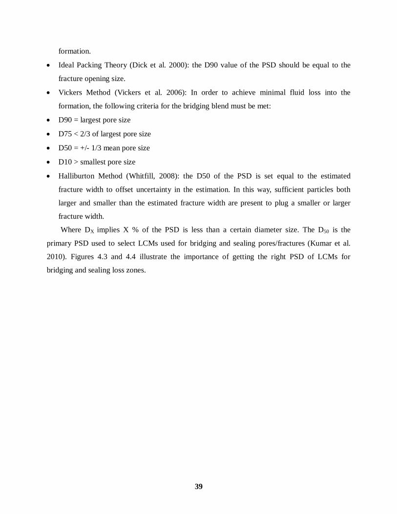
Where DX implies X % of the PSD is less than a certain diameter size. The D50 is the
primary PSD used to select LCMs used for bridging and sealing pores/fractures (Kumar et al.
2010). Figures 4.3 and 4.4 illustrate the importance of getting the right PSD of LCMs for
bridging and sealing loss zones.
39
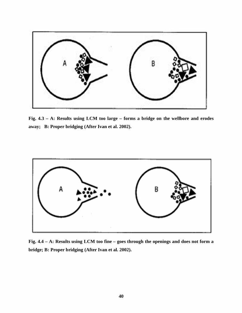
Fig. 4.3 – A: Results using LCM too large – forms a bridge on the wellbore and erodes
away; B: Proper bridging (After Ivan et al. 2002).
Fig. 4.4 – A: Results using LCM too fine – goes through the openings and does not form a
bridge; B: Proper bridging (After Ivan et al. 2002).
40

Higher concentration of LCMs delivered in sweeps can aid in fracture tip screen-out and
prevent fracture propagation (Whitfill and Wang, 2005). As the drilling progresses, additional
make-up LCMs should be added to maintain pretreatment levels. Table 4.1 provides a guideline
on the amount of LCMs to be added to the mud, based on the weight of mud (Ferron et al. 2011):
41
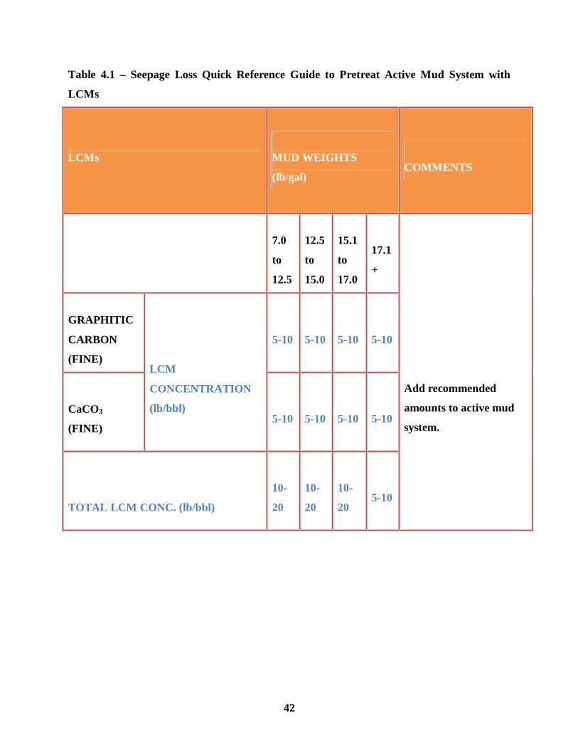
Table 4.1 – Seepage Loss Quick Reference Guide to Pretreat Active Mud System with
LCMs
LCMs
MUD WEIGHTS
(lb/gal)
COMMENTS
7.0
to
12.5
12.5
to
15.0
15.1
to
17.0
17.1
+
Add recommended
amounts to active mud
system.
GRAPHITIC
CARBON
(FINE)
LCM
CONCENTRATION
(lb/bbl)
5-10
5-10
5-10
5-10
CaCO3
(FINE)
5-10
5-10
5-10
5-10
TOTAL LCM CONC. (lb/bbl)
10-
20
10-
20
10-
20
5-10
42
4.3 PARTIAL LOSSES
Partial losses occur when the severity of the loss is in the range of 10-500 bbl/hr. They occur
in gravels; small, natural horizontal fractures; and barely opened induced vertical fractures
(Nayberg, 1987). The use of LCMs in the mud can be used to prevent and cure partial losses in
all the formations mentioned above. The guidelines discussed in the previous sections on
selecting the optimum PSD of these bridging materials must be adhered to. Table 4.2 provides
guidelines on the amounts of LCMs to be added to the active mud system to prevent and cure
partial losses (Ferron et al. 2011).
43
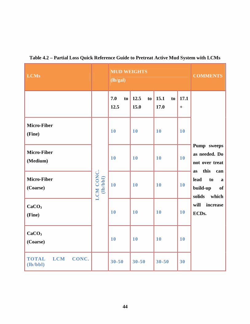
Table 4.2 – Partial Loss Quick Reference Guide to Pretreat Active Mud System with LCMs
LCMs MUD WEIGHTS
(lb/gal) COMMENTS
7.0 to
12.5
12.5 to
15.0
15.1 to
17.0
17.1
+
Pump sweeps
as needed. Do
not over treat
as this can
lead to a
build-up of
solids which
will increase
ECDs.
Micro-Fiber
(Fine)
LC
M C
ON
C.
(lb/
bbl)
10 10 10 10
Micro-Fiber
(Medium) 10 10 10 10
Micro-Fiber
(Coarse) 10 10 10 10
CaCO3
(Fine) 10 10 10 10
CaCO3
(Coarse) 10 10 10 10
TOTAL LCM CONC. (lb/bbl) 30-50 30-50 30-50 30
44
4.4 SEVERE AND TOTAL LOSSES
Mud losses are said to be severe when the rate of loss is greater than 500 bbl/hr. Total
losses occur when no fluid returns is seen through the annulus. These types of losses occur in
long, open sections of gravels; large, natural horizontal fractures; caverns; interconnected vugs;
and widely-opened induced fractures (Nayberg, 1987). Losses into large caverns occur only at
very shallow depths and are difficult to treat. Sometimes, a cure may not be possible and may
require other actions (Ferron et al. 2011). Some of the actions that may be taken include: 1)
Drilling Blind 2) Drilling with Aerated Mud
4.4.1 Blind Drilling (Drilling Without Returns)
This technique is used in severe total lost circulation events, where a cure might not be
possible or where economic analysis of the treatment process is not favorable, to cross the loss
zone in order to set casing. Concerns of drilling blind should include: possible stuck pipe,
insufficient hole cleaning, loss of well control, sloughing formations, etc. (Johnson et al. 2000).
When drilling without returns, it important to maintain a pumping rate equal or greater than the
normal pumping rate used for hole cleaning. Otherwise, there is a risk of sticking the pipe string.
This makes practical access to an adequate water source a necessity if the technique is to be
completed efficiently (Canson, 1985).
Chemical systems that form flexible ultra-viscosity treatments may be necessary to solve
the most severe lost circulation problems (Whitfill and Hemphill, 2003). The most commonly
used chemical systems are Reactant Pills. These pills are used to regain circulation from either
lost circulation or kicks and they have been successfully used for many years to seal off zones or
pathways to underground flows allowing the flowing zone to be killed. Reactant means that the
pill’s final properties will be much different after it has been spotted in the wellbore (Ferron et al.
2011). There are many pill treatments available, including cements, gunk squeezes, cross-linked
gels, and graded particulates (Reid and Santos, 2003). It is important that the operator carries out
a careful study in order to select a pill that will offer several technical and operational
advantages.
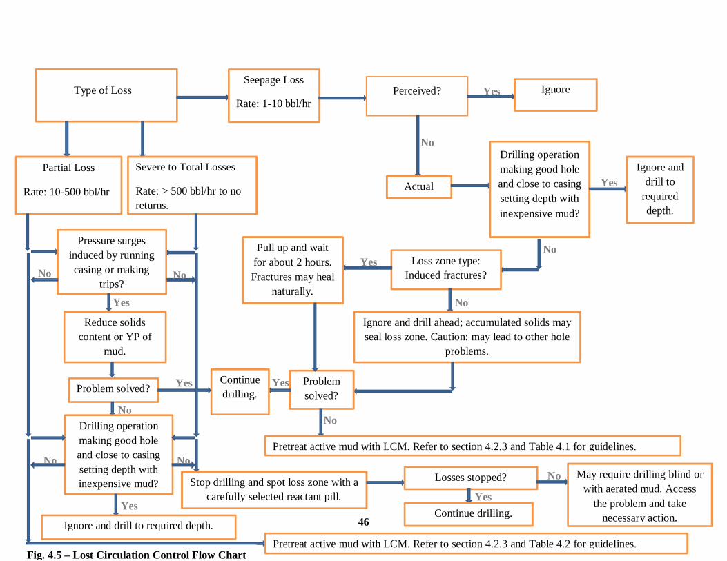
Figure 4.5 provides a summary of the techniques and guidelines on how to combat the
different types of lost circulation cases. When used in combination with the above guidelines, the
problem of lost circulation will be reduced if not totally stopped.
45
Type of Loss Seepage Loss
Rate: 1-10 bbl/hr Perceived? Ignore
Actual
Drilling operation making good hole and close to casing setting depth with inexpensive mud?
Ignore and drill to
required depth.
Loss zone type: Induced fractures?
Pull up and wait for about 2 hours. Fractures may heal
naturally.
Ignore and drill ahead; accumulated solids may seal loss zone. Caution: may lead to other hole
problems.
Problem solved?
Pretreat active mud with LCM. Refer to section 4.2.3 and Table 4.1 for guidelines.
Continue drilling.
Partial Loss
Rate: 10-500 bbl/hr
Severe to Total Losses
Rate: > 500 bbl/hr to no returns.
Pressure surges induced by running casing or making
trips?
Reduce solids content or YP of
mud.
Problem solved?
Drilling operation making good hole and close to casing setting depth with inexpensive mud?
Ignore and drill to required depth.
Pretreat active mud with LCM. Refer to section 4.2.3 and Table 4.2 for guidelines.
Stop drilling and spot loss zone with a carefully selected reactant pill.
Losses stopped?
Continue drilling.
May require drilling blind or with aerated mud. Access
the problem and take necessary action.
Yes
Yes
Yes
Yes
Yes
Yes
Yes
Yes
No
No
No
No
No No No
No
No No
Fig. 4.5 – Lost Circulation Control Flow Chart
46

CHAPTER 5
SUMMARY, CONCLUSIONS, AND RECOMMENDATIONS
5.1 SUMMARY
Lost circulation presents a lot of challenges while drilling. To address these problems, a
number of methods/techniques have evolved over the years. The objectives of this study are: 1)
to review lost circulation control methods that have been applied in the drilling industry till date
2) to provide the successes and the failures of these methods in field applications and 3) to
develop practical guidelines that will serve as a reference material for lost circulation control at
the well-site for drilling personnel.
To achieve these study objectives, a selected number of technical journals, papers,
textbooks, and manuals that address the problem of lost circulation were carefully reviewed and
summarized. The results of this study are practical guidelines that are not biased towards a
particular service industry product but are general to the mitigation of the problem of lost
circulation while drilling. A flow chart has also been developed that will serve as a quick
reference guide for drilling personnel at the well-site.
5.2 CONCLUSIONS
Based on this study, the following conclusions were made:
Successful control or treatment of lost circulation depends on several factors such as
borehole temperature, pressure, depth, and size of the thief zone.
There are no guaranteed methods for solving lost circulation problems entirely but a lot of
approaches can be used to prevent its occurrence, especially those that occur via induced
fractures when drilling formations that are prone to losses.
Practical guidelines have been developed that when used with the accompanying flow chart
will serve as a quick reference guide to prevent and minimize the problem of lost circulation
while drilling.
47
5.3 RECOMMENDATIONS
For future work in this study area, the following recommendations may be considered:
The effect of lost circulation materials (LCMs) on reservoir productivity may be considered
when selecting these materials for lost circulation control.
Since the subject of lost circulation control is very broad, a study may be conducted in a
particular formation type, such as depleted reservoirs, for in-depth understanding of control
measures.
48

NOMENCLATURE
APWD Annular Pressure while Drilling
bbl/hr barrels per hour
BHA Bottom Hole Assembly
CACP Chemically Activated Cross-linked Pills
CDS Casing Drilling Shoe
CwD Casing while Drilling
DOB Diesel-Oil-Bentonite
Dstatic Static Fluid Column above Loss Zone
EAs Expandable Aggregates
ECD Equivalent Circulating Density
FCP Fracture Closure Pressure
FIP Fracture Initiation Pressure
FIT Formation Integrity Test
FPP Fracture Propagation Pressure
FRP Fracture Re-opening Pressure
ID Internal Diameter
ISIP Initial Shut-in Pressure
lb/bbl pounds per barrel
lb/gal pounds per gallon
LCM Lost Circulation Material
LCMSS Lost Circulation Material Squeeze Systems
LOP Leak-off Pressure
LOT Leak-off Test
M-DOB Mud-Diesel-Oil-Bentonite
Mev Mega-electron Volts
MRCS Mud-Reactive-Chemical-Squeeze
MW Mud Weight
NPT Non-productive Time
Pfriction Annular Friction Pressure
49

Phydrostatic Hydrostatic Pressure
Ploss zone Pressure in Loss Zone
PNC Pulse-neutron Capture
PNS Pulse-neutron Spectroscopy
ppg pounds per gallon
Po Pore Pressure
PSD Particle Size Distribution
psi pounds per square inch
PTotal Total Annular Pressure
Pw Wellbore Pressure
R-DOB Reverse-Diesel-Oil-Bentonite
SBM Synthetic-based Mud
SHMAX Maximum Horizontal Stress
Shmin Minimum Horizontal Stress
STF Shear-thickening Fluid
TD Total Depth
TVD True Vertical Depth
XLOT Extended Leak-off Test 0C Degree Celsius 0F Degree Fahrenheit
Effective Tangential (Hoop) Stress
50

REFERENCES
1. Aadnoy, B.S., Belayneh, M., Ariado, M., and Flateboe, R.: “Design of Well Barriers To
Combat Circulation of Losses,” paper SPE 105449 presented at the 2007 SPE/IADC
Drilling Conference and Exhibition held in Amsterdam, The Netherlands, 20-27
February.
2. Abbas, R., Jarouj, H., Dole, S., Effendhly, Junaidi, H., El-Hassan, H., Francis, L.,
Hornsby, L., McCaith, S., Shuttleworth, N., van der Plas, K., Messier, E., Munk, T.,
Nadland, N., Svendsen, R.K., Therond, E., and Taoutaou, S.: A Safety Net for Controlling
Lost Circulation. Oilfield Review (winter, 2003/2004) 20.
3. Abrams, A.: Mud Design to Minimize Rock Impairment Due to Particle Invasion. JPT
(May, 1977) 586.
4. Beda, G., and Carugo, C.: “Use of Mud Microloss Analysis While Drilling to Improve
the Formation Evaluation in Fractured Reservoir,” paper SPE 71737 presented at the
2001 SPE Annual Technical Conference and Exhibition held in New Orleans, Louisiana,
30 September – 3 October.
5. Bell, R.J., and Davies, J.M.: “Lost Circulation Challenges: Drilling Thick Carbonate Gas
Reservoir, Natuna D-Alpha Block,” paper SPE/IADC 16157 presented at the 1987
SPE/IADC Drilling Conference held in New Orleans, LA, 15-18 March.
6. Bruton, J.R., Ivan, C. D., and Heinz, T.J.: “Lost Circulation Control: Evolving
Techniques and Strategies to Reduce Downhole Mud Losses,” paper SPE 67735
presented at the 2001 SPE/IADC Drilling Conference, Amsterdam, The Netherlands, 27
February – 1 March.
7. Canson, B.E.: “Lost Circulation Treatments for Naturally Fractured, Vugular, or
Cavernous Formations,” paper SPE/IADC 13440 presented at the 1985 SPE/IADC
Drilling Conference held in New Orleans, Louisiana, 6-8 March.
8. Carlton, L.A, and Chenevert, M.E.: “A New Approach to Preventing Lost Returns,”
paper SPE 4972 presented at the 1974 49th Annual Fall Meeting of the Society of
Petroleum of AIME held in Houston, Texas, 6-9 October.
51
9. Darugar, Q.A., Szabo, J.J, Clapper, D.K., and McGuffey, G.: “Single-Sack Fibrous Pill
Treatment for High Fluid Loss Zones,” paper SPE 149120 presented at the 2011
SPE/DGS Saudi Arabia Section Technical Symposium held in Al-Khobar, Saudi Arabia,
15-18 May.
10. Davison, J.M., Leaper, R., Cauley, M.B., Bennett, B., Mackenzie, A., Higgins, C.J.,
Shuttleworth, N., and Wilkinson, D.: “Extending the Drilling Operating Window in
Brent: Solutions for Infill Drilling in Depleting Reservoirs,” paper IADC/SPE 87174
presented at the 2004 IADC/SPE Drilling Conference held in Dallas, Texas, U.S.A, 2-4
March.
11. Dick, M.A., Heinz, T.J., Svoboda, C.F., and Aston, M.: “Optimizing the Selection of
Bridging Particles for Reservoir Drilling Fluids,” paper SPE 58793 presented at the 2000
SPE International Symposium on Formation Damage held in Lafayette, Louisiana, USA,
23-24 February.
12. Dyke, C.G., Wu, B., and Millton-Taylor, D.: “Advances in Characterizing Natural-
Fracture Permeability From Mud-Log Data,” paper SPE 25022 presented at the 1992 SPE
European Petroleum Conference held in Cannes, 16-18 November.
13. Ferron, D.J., Smiley, B.E., Reneau, W.P., Ledbetter, S.B., Stephens, M.L., Murray, D.,
Griggs, J., Esparza, C., Goldwood, D.S., Moses, P., and Matthiesen, M.: Lost Circulation
Guide. Drilling Specialties Co. (2011).
14. Fidan, E., Babadagli, T., and Kuru, E.: “Use of Cement As Lost Circulation Material –
Field Case Studies,” paper IADC/SPE 88005 presented at the 2004 IADC/SPE Asia
Pacific Drilling Technology Conference and Exhibition held in Kuala Lumpur, Malaysia,
13-15 September.
15. Freidheim, J., Sanders, M., and Roberts, N.: “Unique Drilling Fluids Additives for
Improved Wellbore Stability and Reduced Losses,” paper presented at the 2008 SEFLU
Conference held in Margarita Island, Venezuela, 19-23 May.
16. Fuller, G.A., Serio, M., Trahan, J., and Langlinais, J.: “A Novel Approach for the
Controlling of Whole Mud Losses while Encountering Productive Formations,” paper
SPE 127718 presented at the 2010 SPE International Symposium and Exhibition on
Formation Damage Control held in Lafayette, Louisiana, USA, 10-12 February.
52

17. Gallardo, H., Cassanelli, J.P., Barret, S., Romero, P., and Mufarech, A.: “Casing-Drilling
Technology (CwD) Mitigates Fluid Losses in Peruvian Jungle,” paper SPE 139065
presented at the 2010 SPE Latin American & Caribbean Petroleum Engineering
Conference held in Lima, Peru, 1-3 December.
18. Gockel, J.F., and Brinemann, M.: “Lost Circulation: A Solution Based on the Problem,”
paper SPE/IADC 16082 presented at the 1987 SPE/IADC Drilling Conference held in
New Orleans, LA, 15-18 March.
19. Gray, G.R., and Darley, H.C.H.: The Composition and Properties of Oil Well Drilling
Fluids. Fourth Edition. Gulf Publishing Company, Houston, Texas (1980).
20. Guo, B., and Rajtar, J.M.: “Volume Requirements for Aerated Mud Drilling,” paper SPE
26956 presented at the 1994 SPE Latin America/Caribbean Petroleum Engineering
Conference held in Buenos Aires, 27-29 April.
21. Hamburger, C.L., Tsao, Y., Morrison, B., and Drake, E.N.: “A Shear-Thickening Fluid
for Stopping Unwanted Flows While Drilling,” paper SPE 12122 presented at the 1983
SPE Annual Technical Conference and Exhibition held in San Francisco, 5-8 October.
22. Howard, G.C., and Scott, P.P.: “AN ANALYSIS AND THE CONTROL OF LOST
CIRCULATION,” paper SPE 951171 presented at the 1951 Annual Meeting of the
AIME held in St. Louis, Mo., 19-21 February.
23. Ivan, C.D., Bruton, J.R., Thiercelin, M., and Bedel, J.: “Making a Case for Rethinking
Lost Circulation Treatments in Induced Fractures,” paper SPE 77353 presented at the
2002 SPE Annual Technical Conference and Exhibition held in San Antonio, Texas, 29
September – 2 October.
24. Ivan, C., and Bruton, R.: “How Can We Best Manage Lost Circulation?” paper AADE-
03-NTCE-38 presented at the 2003 AADE National Technology Conference, Houston,
Texas, 1-3 April.
25. Jiao, D., and Sharma, M.M.: “Mud-Induced Formation Damage in Fractured Reservoirs,”
paper SPE 30107 presented at the 1995 European Formation Damage Control Conference
held in The Hague, The Netherlands, 15-16 May.
53
26. Johnson, L., Murphy, P., and Arsanious, K.: “Improvements in Lost-Circulation Control
During Drilling Using Shear-Sensitive Fluids,” paper PETSOC-2000-062-P presented at
the 2000 Petroleum Society’s Canadian International Petroleum Conference held in
Calgary, Canada, 4-8 June.
27. Kumar, A., Sharath, S., Whitfill, D.L., and Jamison, D.E.: “Wellbore Strengthening: The
Less-Studied Properties of Lost-Circulation Materials,” paper SPE 133484 presented at
the 2010 SPE Annual Technical Conference and Exhibition held in Florence, Italy, 19-22
September.
28. Majidi, R., Miska, S.Z., and Zhang, J.: “Fingerprint of Mud Losses into Natural or
Induced Fractures,” paper SPE 143854 presented at the 2011 SPE European Formation
Damage Conference held in Nordwijk, The Netherlands, 7-10 June.
29. Metcalf, A.S., Nix, K., and Martinez-Guedry, J.: “Case Histories: Overcoming Lost
Circulation During Drilling and Primary Cementing Operations Using an
Environmentally Preferred System,” paper SPE 140723 presented at the 2011 SPE
Production and Operations Symposium held in Oklahoma City, Oklahoma, USA, 27-29
March.
30. Moore, P.L.: Drilling Practices Manual. Second Edition. PennWell Publishing Company.
Tulsa, Oklahoma (1986).
31. Nayberg, T.M.: “Laboratory Study of Lost Circulation Materials for Use in Both Oil-
Based and Water-Based Drilling Muds,” paper SPE 14723 presented at the 1986
IADC/SPE Drilling Conference held in Dallas, 10-12 February.
32. Nayberg, T.M., and Petty, B.R.: “Laboratory Study of Lost Circulation Materials for Use
in Oil-Base Drilling Muds,” paper SPE 14995 presented at the 1986 Deep Drilling and
Production Symposium of the Society of Petroleum Engineers held in Amarillo, TX, 6-8
April.
33. Okland, D., Gabrielsen, G.K., Gjerde, J., Sinke, K., and Williams, E.L.: “The Importance
of Extended Leak-Off Test Data for Combating Lost Circulation,” paper SPE/ISRM
78219 presented at the 2002 SPE/ISRM Rock Mechanics Conference held in Irving, 20-
23 October.
34. Onyekwere, C.: Lost Circulation Material Training Manual. Schlumberger (2002).
54
35. Osisanya, S.: Course Notes on Drilling and Production Laboratory. Mewbourne School
of Petroleum and Geological Engineering, University of Oklahoma, Oklahoma (Spring
2002).
36. Pilehvari, A.A., and Nyshadham, V.R.: “Effect of Material Type and Size Distribution on
Performance of Loss/Seepage Control Material,” paper SPE 73791 presented at the 2002
SPE International Symposium and Exhibition on Formation Damage Control held in
Lafayette, Louisiana, 20-21 February.
37. Ramirez, M., Diaz, A., Luna, E., Figueroa, Y., and Per-Bjarte, T.: “Successful
Application of Synthetic Graphite to Overcome Severe Lost Circulation Problem in the
Troublesome Foothills of Colombia,” paper AADE-05-NTCE-30 presented at the 2005
AADE National Technical Conference and Exhibition held at the Wyndam Greenspoint
in Houston, Texas, 5-7 April.
38. Redden, J., Carpenter, B., Polnaszek, S., Bloys, B., and Headley, J.: Lost Circulation
Manual. MI-SWACO (2011).
39. Reid, P., and Santos, H.: “Novel Drilling, Completion and Workover Fluids for Depleted
Zones: Avoid Losses, Formation Damage and Stuck Pipe,” paper SPE/IADC 85326
presented at the 2003 SPE/IADC Middle East Drilling Technology Conference and
Exhibition held in Abu Dhabi, UAE, 20-22 October.
40. Samsuri, A., and Phuong, B.T.N.: “CHEAPER CEMENT FORMULATION FOR LOST
CIRCULATION CONTROL,” paper IADC/SPE 77216 presented at the 2002 IADC/SPE
Asia Pacific Drilling Technology Conference held in Jakarta, Indonesia, 9-11 September.
41. Sanders, M.W., Scorsone, J.T., and Friedheim, J.E.: “High-Fluid-Loss, High-Strength
Lost Circulation Treatments,” paper SPE 135472 presented at the 2010 SPE Deepwater
and Completions Conference held in Galveston, Texas, USA, 5-6 October.
42. Savari, S., Kumar, A., Whitfill, D.L., and Jamison, D.E.: “Improved Lost Circulation
Treatment Design and Testing Techniques Minimize Formation Damage,” paper SPE
143603 presented at the 2011 SPE European Formation Damage Conference held in
Noordwijk, The Netherlands, 7-10 June.
55
43. Shun Chang, W., YiMing, J., ChunJiang, Z., BaiLin, W., XinQuan, Z., JiPing, T., JinHai,
Y., and HongHai, F.: “Real-Time Downhole Monitoring and Logging Reduced Mud Loss
Drastically for High-Pressure Gas Wells in Tarim Basin, China,” paper IPTC 12865
presented at the 2008 International Petroleum Technology Conference held in Kuala
Lumpur, Malaysia, 3-5 December.
44. Song, J.H., and Rojas, J.C.: “Preventing Mud Losses by Wellbore Strengthening,” paper
SPE 101593 presented at the 2006 SPE Russian Oil and Gas Technical Conference and
Exhibition held in Moscow, Russia, 3-6 October.
45. Suyan, K.M., Dasgupta, D., Sanyal, D., Shama, V., and Jain, V.K.: “Managing Total
Circulation Losses With Crossflow While Drilling: Case History of Practical Solutions,”
paper SPE 109898 presented at the 2007 SPE Annual Technical Conference and
Exhibition held In Anaheim, California, USA, 11-14 November.
46. Sweatman, R.E., Kessler, C.K., and Miller, J.M.: “New Solutions to Remedy Lost
Circulation, Crossflows, and Underground Blowouts,” paper SPE/IADC 37671 presented
at the 1997 SPE/IADC Drilling Conference held in Amsterdam, The Netherlands, 4-6
March.
47. Sweatman, R., Faul, R., and Ballew, C.: “New Solutions for Subsalt-Well Lost
Circulation and Optimized Primary Cementing,” paper SPE 56499 presented at the 1999
SPE Annual Technical Conference and Exhibition held in Houston, Texas, 3-6 October.
48. Tare, U.A., Whitfill, D.L., and Mody, F.K.: “Drilling Fluid Losses and Gains: Case
Histories and Practical Solutions,” paper SPE 71368 presented at the 2001 SPE Annual
Technical Conference and Exhibition held in New Orleans, Louisiana, 30 September – 3
October.
49. Tessari, R., Madell, G., and Warren, T.: Drilling with casing promises major benefits. Oil
and Gas Journal (May, 1999).
50. Tessari, R.M., Warren, T.M., and Jo, J.Y.: “Drilling with Casing Reduces Cost and
Risk,” paper SPE 101819 presented at the 2006 SPE Russian Oil and Gas Technical
Conference and Exhibition held in Moscow, Russia, 3-6 October.
56
51. van Oort, E., Friedheim, J., Pierce, T., and Lee, J.: “Avoiding Losses in Depleted and
Weak Zones by Constantly Strengthening Wellbores,” paper SPE 125093 presented at the
2009 SPE Annual Technical Conference and Exhibition held in New Orleans, Louisiana,
USA, 4-7 October.
52. Vickers, S., Cowie, M., Jones, T., and Allan, J.T.: “A New Methodology that Surpasses
Current Bridging Theories to Efficiently Seal a Varied Pore Throat Distribution as Found
in Natural Reservoir Formations,” paper AADE-06-DF-HO-16 presented at the 2006
AADE Fluids Conference held in Houston, Texas, USA, 11-12 April.
53. Vidick, B., Yearwood, J.A., and Perthuis, H.: “How To Solve Lost Circulation
Problems,” paper SPE 17811 presented at the 1988 SPE International Meeting on
Petroleum Engineering held in Tianjin, China, 1-4 November.
54. Vinson, E.F., Totten, P.L., and Middaugh, R.L.: “Acid Removable Cement System Helps
Lost Circulation in Production Zones,” paper IADC/SPE 23929 presented at the 1992
IADC/SPE Drilling Conference held in New Orleans, Louisiana, 18-21 February.
55. Wang, H., Sweatman, R., Engelman, B., Deeg, W., Whitfill, D., Soliman, M., and
Towler, B.: “Best Practice in Understanding and Managing Lost Circulation Challenges,”
paper SPE 95895 presented at the 2005 SPE Annual Technical Conference and
Exhibition held in Dallas, Texas, 9-12 October.
56. Wang, H., Soliman, M.Y., Towler, B.F., and Shan, Z.: “Strengthening a Wellbore with
Multiple Fractures: Further Investigation of Factors for Strengthening a Wellbore,” paper
ARMA 09-67 presented at the 2009 43rd US Rock Mechanics Symposium and 4th US-
Canada Rock Mechanics Symposium held in Asheville, NC, 28 June – 1 July.
57. White, R.J.: “Lost-Circulation Materials and their Evaluation,” presented at the 1956
Panel Discussion on Lost Circulation held at the Spring Meeting of the Pacific Coast
District, Division of Production, Los Angeles, in May.
58. Whitfill, D.L., and Hemphill, T.: “All Lost-Circulation Materials and Systems Are Not
Created Equal,” paper SPE 84319 presented at the 2003 SPE Annual Technical
Conference and Exhibition held in Denver, Colorado, U.S.A., 5-8 October.
59. Whitfill, D., and Wang, H.: “Making Economic Decisions To Mitigate Lost Circulation,”
paper SPE 95561 presented at the 2005 SPE Annual Technical Conference held in Dallas,
Texas, U.S.A., 9-12 October.
57

60. Whitfill, D.: “Lost Circulation Material Selection, Particle Size Distribution and Fracture
Modeling with Fracture Simulation Software,” paper IADC/SPE 115039 presented at the
2008 IADC/SPE Asia Pacific Drilling Technology Conference and Exhibition held in
Jakarta, Indonesia, 25-27 August.
58