practical aspects determining the modelling of the space
TRANSCRIPT
Proceedings of the International Association for Shell and Spatial Structures (IASS) Symposium 2009, Valencia Evolution and Trends in Design, Analysis and Construction of Shell and Spatial Structures
28 September – 2 October 2009, Universidad Politecnica de Valencia, Spain Alberto DOMINGO and Carlos LAZARO (eds.)
Practical aspects determining the modelling of the space structure for the free-form envelope enclosing
Baku's Heydar Aliyev Cultural Centre Jaime SANCHEZ-ALVAREZ*
*Structural Geometry Designer MERO-TSK International GmbH & Co. KG.
Max-Mengeringhausen-Strasse 5 D-97084 Würzburg, Germany
jaime.sanchez@mero-tsk
Abstract Zaha Hadid Architects designed a complex free-form envelope to house the new Heydar Aliyev Cultural Centre in Baku, Azerbaijan. The cultural centre comprises a library, an auditorium and a museum together with other complementary facilities. The architectural space envelope is double layered, that is, it consists of an external and an internal skin with a variable distance in between. A special requirement for the appearance of the cladding panels is the paths of their intermediate joints, which visibly run parallel in one direction, thus accentuating the smoothness of the surface and suggesting a natural flow. The present paper discusses and illustrates how visual, architectural and constructional requirements posed very demanding conditions for designing and modelling the MERO-TSK space structure, which is the actual structural system not only supporting the space envelopes, but a convenient form-giving construction basis to materialise their cladding surfaces. Keywords: Free-form, Geometry, modelling, morphology, NURBS, space structures.
1. Introduction Figures 1 and 2 give an impression of the free-form envelopes for the Baku Cultural Centre. The first image shows an external view of the free-form envelope with the Museum on the left and the Library and Auditorium on the right-hand side. The second image shows an internal view of the Library. Both, external and internal skins appear as clean and continuous surfaces, which have been subdivided in bands by means of visible curvilinear joints (or gaps) running parallel in one direction. Thus, the general requirement for the structural system supporting the envelopes was to provide a construction on which the cladding panels materialising the skins could be put together and fixed to obtain the
1263

Proceedings of the International Association for Shell and Spatial Structures (IASS) Symposium 2009, Valencia Evolution and Trends in Design, Analysis and Construction of Shell and Spatial Structures
required visual appearance, on the one hand, and to fulfil the functional aspects of an architectural envelope, such as structural soundness and climatic control, on the other hand.
Figure 1: Heydar Aliyev Cultural Centre, Baku (image: Zaha Hadid Architects), with the Museum on the left and the Library and the Auditorium on the right.
Figure 2: Heydar Aliyev Cultural Centre, Baku (image: Zaha Hadid Architects), internal view of Library space.
1264
Proceedings of the International Association for Shell and Spatial Structures (IASS) Symposium 2009, Valencia Evolution and Trends in Design, Analysis and Construction of Shell and Spatial Structures
After the obligatory phase of feasibility studies and tendering, a classical MERO-TSK spherical-node space frame system was chosen to materialise the structure. A spherical- node space frame system mainly because of its flexibility at connecting tubular members of practically any diameter and length at the spherical connectors by means of bolts. In the case of MERO-TSK space frames, a high flexibility in construction is coupled with a highly automated production line, which allows the fabrication of components with different geometry in a very short time, in large quantities and in an extremely economic way. In addition, the ISO-certified accuracy of fabrication facilitates the assembly of the construction on site and it guarantees the required global geometric shape. The task of the structural geometry designer here is to use the possibilities and advantages of the chosen construction system, under consideration also of its limitations, to design a spatial structural network which satisfies in the best possible way as many requirements as possible.
2. Constraint-free geometric optimisation of a structural network ? No, if the structural network is going to be built. When one thinks of geometric optimisation of a structural network on an arbitrary surface, high regularity and homogeneity of member lengths, node angles and mesh or panel types are the usual targets. A minimum number of different element types will reflect directly in the economics of the resulting structural and cladding components, their fabrication and assembly of the real construction. However, other architectural and functional requirements often weight more in a free-form design than the geometric optimisation alone and they have to be considered in the geometric modelling and geometric optimisation process according to their higher relevance, their interaction with other design parameters and their combined impact on the whole design. The space frame geometry proposed for the Baku cultural centre is the commonly used square-on-offset-square double-layered grid, one application of which is shown in Figure 3. It should be clear, however, that this configuration has been taken to define the topological network and not the metric of the structure. The metric of the structure was obtained by geometrically constructing or mapping polygons and quadrangular networks on the free-form or NURBS surfaces provided by the architectural design and interconnecting them as in the chosen space frame topological configuration. The fact that more than 80 if not 90% of the space frames in the world are still being built in the square-on-offset-square layout speaks more for the great flexibility of this configuration when subjected to geometric distortions while preserving its structural function and its constructional feasibility than for lack of imagination. The cladding envelope for the cultural centre, although conceived as a single free-form surface, has been divided due to constructional reasons into two structure-cladding systems, namely, the larger part consisting of the auditorium-library group and the smaller building of the museum. A comprehensive preliminary structural and constructive analysis considering aspects such as the necessary structural depth for the given spans, the given distance between interior and exterior skins, the practical sizes of cladding elements and the
1265

Proceedings of the International Association for Shell and Spatial Structures (IASS) Symposium 2009, Valencia Evolution and Trends in Design, Analysis and Construction of Shell and Spatial Structures
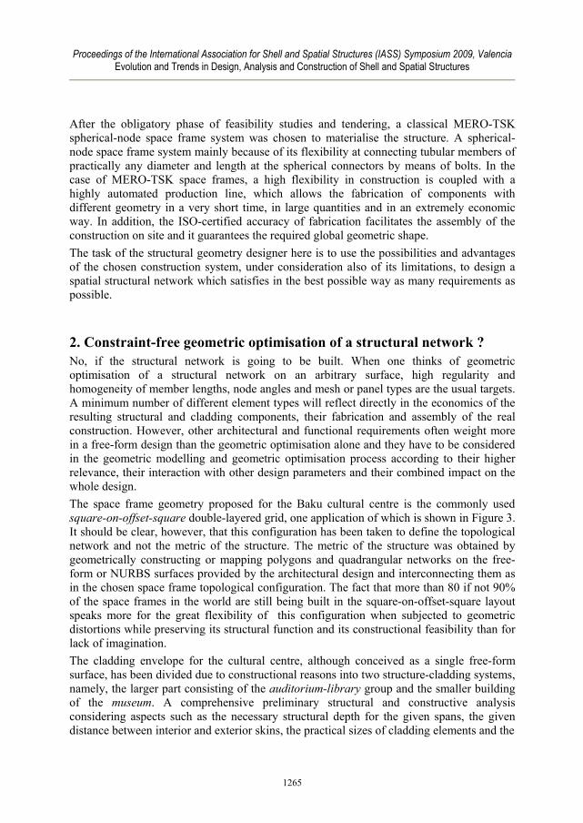
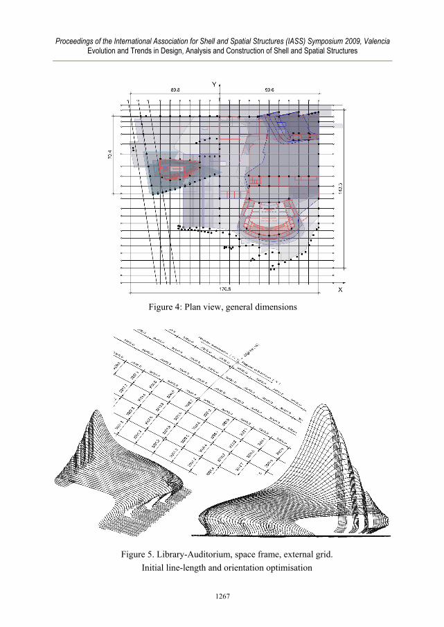
relation between mesh member lengths and curvature of the cladding surfaces required different module sizes and structural depths for the two space structures. Thus, the library-auditorium envelope’s structure has a basic mesh length of about 3.0 m and a variable structural depth also of around 3.0 m, while the museum has a basic mesh length of about 2.3 m and a variable structural depth or around 1.0 m. Having a basic space frame geometry for the project, a geometric optimisation exercise for the external networks of the space frames was carried out within the initial feasibility study. The first determining parameter here was the orientation of the cladding seams in the NURBS-surface model provided by the architect, namely the direction indicated with “Y” on the plan view of Figure 4, where the overall plan dimensions of the complex can also be seen. One set of lines of the structural quadrangular grid were to run every 3.0 m parallel on plan view to this direction. These lines fit exactly within the constant 9.0 m between adjacent building axes. The corresponding curves in 3D space for the external layer of the structure are obtained by parallel projection of horizontal parallel straight lines on the corresponding carrier NURBS- surface. As a next step, an “origin” line on the NURBS-surface was drawn at the middle of the Y-extension of the roof, cutting across the previously generated curves at 90° on plan view, that is, in the X-direction. Then, every curve on the NURBS-surface was subdivided in straight line segments of 3.0 m in +Y and –Y starting at the origin line, as Figure 5 shows. With this action, all line segments in Y have a constant length of 3.0 m, and they visibly run in the prescribed direction. The quadrangular grid on the NURBS-surface is completed by connecting neighbouring points in X with straight line segments, which will necessarily have different true lengths of at least 3.0 m. This optimisation procedure is summarised in Figure 5.
Figure 3: MERO-TSK space frame with square-on-offset square double-layered grid
1266
Proceedings of the International Association for Shell and Spatial Structures (IASS) Symposium 2009, Valencia Evolution and Trends in Design, Analysis and Construction of Shell and Spatial Structures
Figure 4: Plan view, general dimensions
Figure 5. Library-Auditorium, space frame, external grid. Initial line-length and orientation optimisation
1267

Proceedings of the International Association for Shell and Spatial Structures (IASS) Symposium 2009, Valencia Evolution and Trends in Design, Analysis and Construction of Shell and Spatial Structures
3. Aspects modifying the initial geometric optimisation The above described initial line-length and orientation optimisation set an ideal geometric optimisation strategy and target for the external an the internal layers of both space structures of the cultural centre. However, there was a series of more relevant architectural and constructional requirements, which either enforced the adaptation and modification of the initially optimised grids or allowed only a regional application of the geometric optimisation procedure.
3.1. Supports positions and interaction with internal architectural elements Interior supports and facade support columns are in general vertical and their centres lie at the intersections of building axes. The axes in the Y-direction run every 9.0 m, while the distance between the axes in the X-direction vary. The nodes of the internal grid of the space frame had to be positioned on plan view along the building axes, so that the vertical axis of a column always coincides with a node of the internal structural grid. In areas where the roof supports lie on walls that do not coincide with the building axes, the internal structural grid has been adapted as necessary with minimal distortions. It should be noted, that in rather horizontal roof areas the fixed positions of vertical supports disrupted the constant length optimisation. However, the grid adaptation here is barely perceptible. There are areas in both buildings where the spatial envelopes intersect with interior architectural elements, like shafts, stairs, walls and building cores. Here, adequate openings and local adaptations for supports had to be made in the structural grids to cope with the various situations. Figure 6 shows in plan view the resulting internal and external grids for both space structures, where the off-set relation between both grids can be appreciated. Figure 6. Internal (left) and external (right) structural grids,
adapted to supports positions and other architectural elements
1268

Proceedings of the International Association for Shell and Spatial Structures (IASS) Symposium 2009, Valencia Evolution and Trends in Design, Analysis and Construction of Shell and Spatial Structures
The left part of Figure 7 shows modifications that had to be done to the interior structural grid of the space frame of the Museum to form constructive interfaces, later supports consoles, at the free-form top of the Museum’s concrete core walls. The right part of Figure 7 shows in turn substantial adaptations that had to be done on the double-layered grid to achieve a structurally sensible interrelation with a series of 1000. mm high, curved, steel H-beams supporting the concrete slabs at the –Y wall of the building. Here, the space frame elements and the vertical H-beams have to share a very reduced inter-skin space of about 1.0 m and they are modelled in such a way, that they do not interact structurally, except for an acceptable horizontal stabilising interaction.
3.2. Variable distance between interior and exterior skins The distance between interior and exterior skins is variable. In the Library-Auditorium space it varies between 1.0 and 7.0 m, while in the Museum it varies between 1.0 and 2.0 m, approximately. However, the carrier surfaces for the interior and exterior structural grids are not the NURBS-surfaces of the skins in the architectural model, but normal offsets of them, where the offset distance is defined by the volume required for the climatic insulation package and its supporting substructure and other installations. Thus, the inwards offset for the external structural grid was set to 950. mm, whereas the inwards offset for the internal structural grid was set to 600. mm. In other words, the distance between structural carrier surfaces is reduced by 1.55 m with respect to the distance between interior and exterior cladding surfaces. The variable distance between interior and exterior structural grids determined in general the depth of the space structure. On the other hand, the structural depth for the Library-Auditorium roof was limited to 3.0 m due to feasibility of construction aspects. That is, larger structural depths would cause too small, non-economic, angles between members
Figure 7. Interaction of double-layered structural grid with interior architectural elements at the Museum
1269

Proceedings of the International Association for Shell and Spatial Structures (IASS) Symposium 2009, Valencia Evolution and Trends in Design, Analysis and Construction of Shell and Spatial Structures
interconnecting interior and exterior structural grids. In roof areas with larger inter-skins distances, the substructure to fix the ceiling has to bridge the remaining distance. In wall areas with larger inter-skins distances, some of which amount to 6.5 m, the space structure had to be complemented with additional layers to reach the nominal carrier surface for the interior structural grid. On the other hand, there are envelope areas where the inter-surface distance between structural grids diminished gradually to almost impracticable structural depths of 500. mm, 0.0 mm and unrealistic negative distances. In these areas, approaching some edges of the envelope, the double-layered space frame stops at the constructability limit, where an interface to a one-layered conventional structure was devised. In areas beyond the intersection of internal and external structural surfaces, the substructure of the cladding package has to be self-supporting. Figures 8 and 9 show typical inter-skin distance situations at the Library-Auditorium and the Museum envelopes, respectively.
Figure 8. Typical Y-sections of Library-Auditorium, showing the variable inter-skin distance and the enclosed space structure
Figure 9. Y-section of Museum on the left and X-section through both buildings on the right, showing the variable inter-skin distance and the enclosed space structure
1270

Proceedings of the International Association for Shell and Spatial Structures (IASS) Symposium 2009, Valencia Evolution and Trends in Design, Analysis and Construction of Shell and Spatial Structures
3.3. The apron at the Museum and the dovetails at the Library-Auditorium The apron of the Museum at the –X vertical facade of the building is a large envelope area dropping outwards from the middle of the roof area, as a heavy elastic piece of cloth touching the base floor with its curved edge. The apron portion of space frame has a gradual reduction of structural depth of 1.60 m at the roof to approximately 600. mm at its base, where it connects to a single-layered extension of the external double-layered grid. The geometric-constructive situation of the apron is illustrated at the top left of Figure 10. The so called dovetail terminal portions of envelope at the –Y side of the Library-Auditorium complex have extreme form and curvature variations and they end at an 800. mm wide fascia surface connecting interior and exterior cladding skins. The inter-skin space in these areas is rather small and the resulting portions of space frame gradually get a minimum practicable depth of about 500. mm. More than a geometric optimisation, the geometric modelling here was aimed at making the construction geometry possible, while still fulfilling the structural, climatic and visual requirements. Figure 10 shows at the bottom right part the transition from the two-layered space structure to the one-layered conventional steel structure, which is self-supporting. Figure 10. Top left: X- mid section of Museum through the apron, depicting the
transition from the two to the one-layered structure. - Bottom right: The complex transition of double-layered space frame to one-layered construction of curved steel
sections at the terminal dovetails in the Library-Auditorium
1271

Proceedings of the International Association for Shell and Spatial Structures (IASS) Symposium 2009, Valencia Evolution and Trends in Design, Analysis and Construction of Shell and Spatial Structures
4. The final model of the space structures The final 3D line model of the space structures for the Baku Cultural Centre served as the basis for the subsequent structural analysis and CAD processing of the construction and for the generation of geometric information for the NC-driven fabrication of the space frame components. Also, the model constituted the geometric-constructional basis for the further engineering and construction of the enclosing cladding surfaces.
Figure 11. Complete space frame model, north external view
Figure 12. Complete space frame model, south external view
1272

Proceedings of the International Association for Shell and Spatial Structures (IASS) Symposium 2009, Valencia Evolution and Trends in Design, Analysis and Construction of Shell and Spatial Structures
Figure 13. Complete space frame model, Library-Auditorium, view from below
Figure 14. Complete space frame model, Museum (l) and Library (r), view from below
1273

Proceedings of the International Association for Shell and Spatial Structures (IASS) Symposium 2009, Valencia Evolution and Trends in Design, Analysis and Construction of Shell and Spatial Structures
5. Concluding remarks The intention of the present paper has been to illustrates how visual, architectural and constructional requirements often pose very demanding conditions for designing, modelling and geometrically optimise the structural systems in an architectural project. The space frame system chosen to support the envelopes for the Heydar Aliyev Cultural Centre in Baku has been taken as an specific example. This space frame has been designed not only as “a” supporting system, but as a convenient form-giving construction basis to materialise the cladding surfaces and to make possible the desired visual effect of the space envelopes. Within the framework of the general design parameters, a line-length optimisation coupled with a line-orientation strategy has been followed whenever possible to achieve a highly homogeneous and continuous configuration.
Acknowledgements A complex geometric design is not the one-step product of a single person. It develops often very organically and iteratively from the interactions of individuals of different disciplines, who seem to be kept working together by the common project targets. Thus, I acknowledge in particular the contributions of my colleagues at MERO-TSK in shaping the geometric model of the space structure for the new Cultural Centre in Baku by producing ideas and sharing with me their knowledge and experience. The Rhino-3D Model of Zaha Hadid Architects with the "architecture" of the project was an invaluable basis to develop the geometric model of the MERO-TSK space frame. The geometric 3D modelling of the envelope's structure was carried out in Rhino 4.0. The resulting Rhino-models were extended with additional information for the MERO-specific technical processing by means of specially developed software tools.
References [1] MERO-TSK Website www.mero-tsk.de [2] www.zaha-hadid.com [3] www.rhino3d.com [4] Pottmann, Helmut; Asperl, A.; Hofer, M.; Kilian, A., “Architectural Geometry“,
Bentley Institute Press, Exton, Pennsylvania, USA, 2007. [5] Sanchez-Alvarez, Jaime. "MERO: A constant in the evolution from regular to free-
form spatial structures", IASS-SLTE 2008 Symposium, Book of Abstracts, pp.239-240, and as Paper 131, 13 pages, in CD-ROM, Ed. Oliva Salinas, Juan G.. Grupo Editorial Formato, S.A. de C.V., Mexico, D.F., 2008.
1274