practical radiated rf immunity system design considerations · 1 practical radiated rf immunity...
TRANSCRIPT
1
Practical Radiated RF Immunity System
Design Considerations
CONDUCTED RF EQUIPMENT POWER AMPLIFIERS

ISO 11452 SAE J1113
General Principles -1 /1
Absorber Lined Chamber -2 /21
TEM Cell -3 /24
Harness Excitation (BCI & TWC) -4 /4
Stripline -5 /23
Parallel Plate (Triplate) Withdrawn /25
Direct Injection -7 /3
Magnetic Fields -8 /22
Portable transmitters -9
Extended Audio -10 /2
Reverberation Chamber -11 /27
Relevant Standards
Designing a System
• Determining what Power Amplifier to select depends on
– The test level required by the standard
– The type of modulation required
– The antenna efficiency (Gain)
– The test environment
– Cable and other component losses
3

Usable Amplifier Power • Saturated Power (Psat) Vs Linear Power (P1dB)
• Definitions
– Psat – Highest power that the amplifier can generate
– P1dB – Highest power where Pin Vs Pout curve is considered to
be straight
4
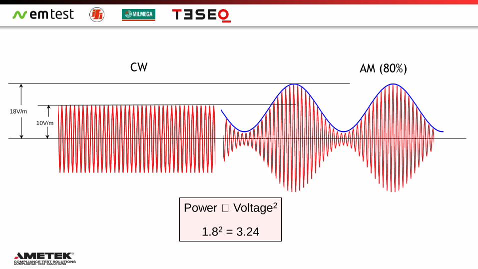
CW AM (80%)
10V/m
18V/m
Power Voltage2
1.82 = 3.24

80% AM with Peak Conservation
CW AM (80%) With Peak Conservation
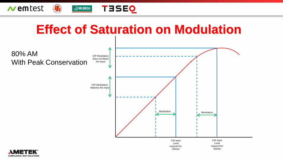
Effect of Saturation on Modulation
CW Input
Level
required for
200mA
Modulation
CW Input
Level
required for
200mA
Modulation
O/P Modulation
Matches the Input
O/P Modulation
does not Match
the Input
80% AM
With Peak Conservation

Pulse Modulation
CW (unmodulated signal) Pulse Modulation
Pulse
Duration
Period
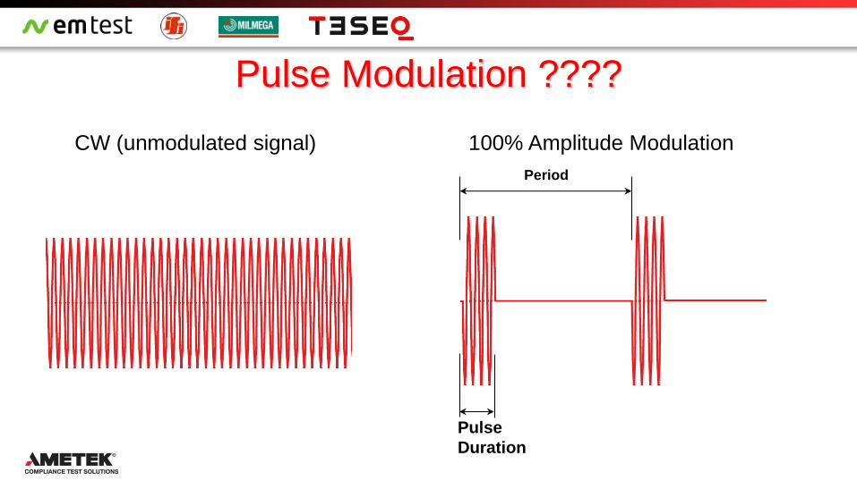
Pulse Modulation ????
CW (unmodulated signal) 100% Amplitude Modulation
Pulse
Duration
Period
Effect of Saturation on Modulation
CW Input
Level
required for
200V/m
Modulation
O/P Modulation
Matches the Input
Pulse

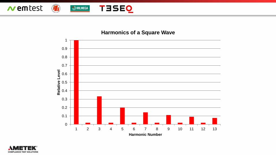
Harmonics
Unwanted signals produced at multiples of the required
fundamental frequency
Specified as dBc
Difference (in dB) between the level of the harmonic and the level of the
intended signal or ‘Carrier’.

What Happens to the Harmonics at and
above P1dB


0
0.1
0.2
0.3
0.4
0.5
0.6
0.7
0.8
0.9
1
1 2 3 4 5 6 7 8 9 10 11 12 13
Rela
tiv
e L
ev
el
Harmonic Number
Harmonics of a Square Wave

Radiated Immunity Power required depends on the test level and the selected antenna
Trade of between efficiency and size at low frequency
Larger antenna are more efficient, if they will fit in the chamber

Basic Radiated Field/Power Calculation
Power required to generate a field of E V/m
at a distance d metres from the antenna
Power (watts) = (E2 * d2) /( 30 * g)
g = 10 (G/10) {g = ratio gain, G = gain (dBi) }

Additional Factors to Consider
Antenna gain varies with the separation distance
between the antenna and the measuring device
Close to the antenna the presence of the antenna
itself effects the parameters of the environment
Some antenna suppliers show gain figures at
various distances
Always use the correct values if available or
make allowance if not
Around 3dB gain reduction between 3 and 1
metre values is typical

Loss in Cables and components
Test Rack to Antenna
1.5m rack to penetration (Loss 0.25 dB @ 1GHz)
5m penetration to floor panel (underfloor cable) (Loss 0.8 dB @ 1GHz)
3m floor panel to antenna (Loss 0.5 dB @ 1GHz)
Internal to rack
0.4m RF switch output – rack bulkhead (Loss 0.1 dB @ 1GHz)
0.4m Directional Coupler output – RF switch input (Loss 0.1 dB @ 1GHz)
Werlatone C5982 Directional Coupler (Loss 0.1 dB @1GHz)
RF Switch – 2 Way N type (Loss 0.1 dB @ 1 GHz)
TOTAL LOSS 1.95 dB @ 1 GHz
Would be lower at 80MHz but much higher at 3GHz
Typical example

Additional Factors to be included
Some standards require the EUT to be placed above a metal ground
plane on a table at the height of the centre of the antenna
This ground plane can add as much as another 3dB to the power
required
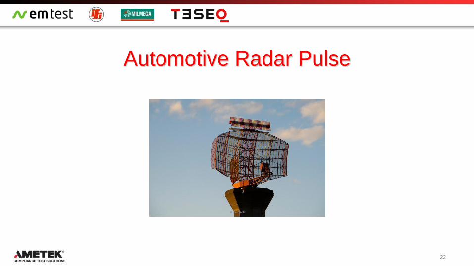

Automotive Radar Pulse
Many establishments use radar systems designed to scan at ground level
This is used at airports to control aircraft during taxi and take off
Such systems are also used for security at airports and military establishments
This represents a severe threat to a vehicle when the high fields impact on safety
critical electronic components for example; airbags, ABS, collision avoidance systems
Field strengths can be very high but the duration of the interference is short
Radar is a made up of a series of very short pulses
As the radar antenna rotates the beam will only hit a vehicle for a short time
23
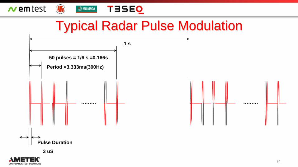
Typical Radar Pulse Modulation
Period =3.333ms(300Hz)
Pulse Duration
3 uS
50 pulses = 1/6 s =0.166s
1 s
……… ………
24

Automotive Radar Pulse Test
Standards bodies and automotive manufacturers have defined the test conditions
Frequencies usually in two bands 1.2-1.4GHz and 2.7-3.1GHz (3.2GHz)
Test levels 300 or 600V/m
Typically amplifier power in the region of 500 – 1000 Watts is required depending on
test level and the antenna selected
Whole vehicle testing requires different antenna and much higher power amplifiers
Please contact your local Ametek CTS sales office for further information on the available high power amplifiers
25
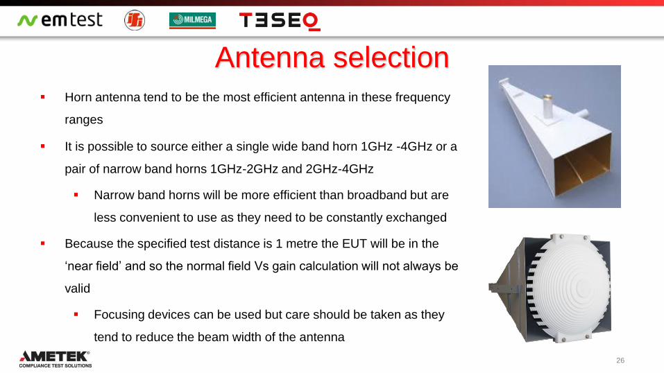
Antenna selection Horn antenna tend to be the most efficient antenna in these frequency
ranges
It is possible to source either a single wide band horn 1GHz -4GHz or a
pair of narrow band horns 1GHz-2GHz and 2GHz-4GHz
Narrow band horns will be more efficient than broadband but are
less convenient to use as they need to be constantly exchanged
Because the specified test distance is 1 metre the EUT will be in the
‘near field’ and so the normal field Vs gain calculation will not always be
valid
Focusing devices can be used but care should be taken as they
tend to reduce the beam width of the antenna
26
Three Techniques
In most radiated immunity tests an isotropic field probe is used to measure
the field during the calibration phase
Normal Isotropic field probes cannot react fast enough to measure the short
duration pulses for the radar pulse test
Different techniques are required for the system calibration and these
depend on the type of amplifier used
There are benefits and disadvantages to each technique
27

Three Amplifier Types
CW amplifier (are able to output maximum power continuously)
Pulse Amplifier (can output full power pulses but no CW)
Pulse/CW amplifier (can output reduced power continuously or full power pulses)
28

CW amplifier (can output maximum power continuously)
Tests can be run in a similar manner to all other RI tests
Calibrate at the specified test level and then during the test apply the required
modulation
Can use all of the available power from the amplifier (in some cases even at saturation)
Standard Isotropic field probe can be used
Amplifier is bigger
Amplifier is more expensive
Advantages
Disadvantages
29

Pulse Amplifier (can output full power pulses but no CW)
Lowest cost
Calibration requires use of a calibrated receive antenna and spectrum analyser
Antenna can integrate field over larger area resulting in potentially inaccurate
measurement
Close coupling of the transmit and receive antenna could give less accurate readings
Pulse measuring field probes are available but are expensive and cannot be used for
other applications
Advantages
Disadvantages
30

Pulse/CW amplifier (can output reduced power continuously or full power pulses)
Lower cost
Can use isotropic field probe for calibration
Calibrate at low CW level and scale power to achieve required level in pulse
Must rely on linearity of amplifier
Not possible to know if you are driving the amplifier into saturation
Near saturation linearity of amplifier cannot be used to calculate field
Advantages
Disadvantages
31

Amplifiers available from Ametek CTS
AS0104R-280/150
Dual band CW
Saturated power 1.2-1.4GHz 280 watts, 2.7-3.1GHz 150 watts
Saturated power 1-2GHz 200 watts, 2-4GHz 100 watts
AS0104R-280/300
Dual band CW
Saturated power 1.2-1.4GHz 280 watts, 2.7-3.1GHz 300 watts
Saturated power 1-2GHz 200 watts, 2-4GHz 220 watts
32
AS0104R-500/300
Dual band CW
Saturated power 1.2-1.4GHz 500 watts, 2.7-3.1GHz 300 watts
Saturated power 1-2GHz 400 watts, 2-4GHz 200 watts

Amplifiers available from Ametek CTS
AS0102R-1500
Single band CW
Saturated power 1.2-1.4GHz 1500 watts
Saturated power 1-2GHz 1000 watts
AS0104R-800/400 (New Product)
Dual band CW
Saturated power 1.2-1.4GHz 800 watts, 2.7-3.1GHz 400 watts
Saturated power 1-2GHz 500 watts, 2-4GHz 350 watts
S31-500-900P (New Product)
Single band CW/Pulse
0.8 - 3.1GHz
500 watts CW
900 watts Pulsed
33

AS0104-800/400
34

S31-500-900P
35

Saturation Vs P1dB
What is it that normally prevents us from
using all the power that the amplifier can
provide?
i.e. running the amplifier at saturation
There are two main reasons:
Distortion of Amplitude Modulated
(AM) signal
High Harmonic levels
36
CW
Input
Level
required
for
200mA
Modulation
CW
Input
Level
required
for
200mA
Modulation
O/P
Modulation
Matches the
Input
O/P
Modulation
does not
Match the
Input
Modulation
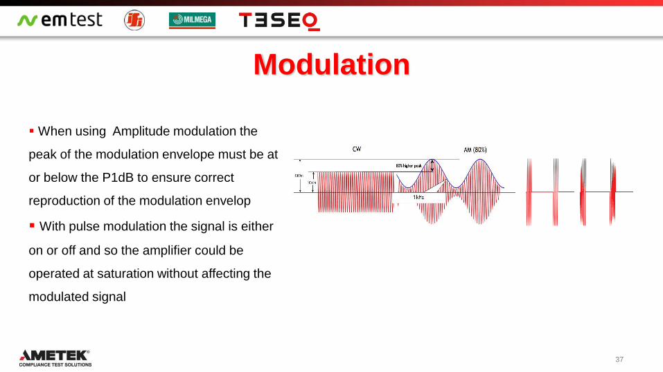
When using Amplitude modulation the
peak of the modulation envelope must be at
or below the P1dB to ensure correct
reproduction of the modulation envelop
With pulse modulation the signal is either
on or off and so the amplifier could be
operated at saturation without affecting the
modulated signal
37

Harmonics When an amplifier is saturated the power devices produce high levels of harmonics but in order for these to be
delivered to the amplifier output the tuning components must be able to transmit these frequencies.
A broadband amplifier covering 1-6GHz or more would be able to produce these harmonics
Harmonics of 1.2GHz = 2.4, 3.6, 4.8GHz which are all in band for a 1-6GHz amplifier
Harmonics of 1.4GHz = 2.8, 4.2, 5.6GHz which are all in band for a 1-6GHz amplifier
However a dual band amplifier with each band covering an octave (1-2GHz and 2-4GHz) or less would not
produce high levels of harmonics as the harmonics would be out of band
Therefore this type of amplifier can be used at saturation
IMPORTANT NOTE
This only applies if system is calibrated CW at the full test level
Calibrating at a low CW level and scaling is not acceptable since the test level is above the linear region
38

39
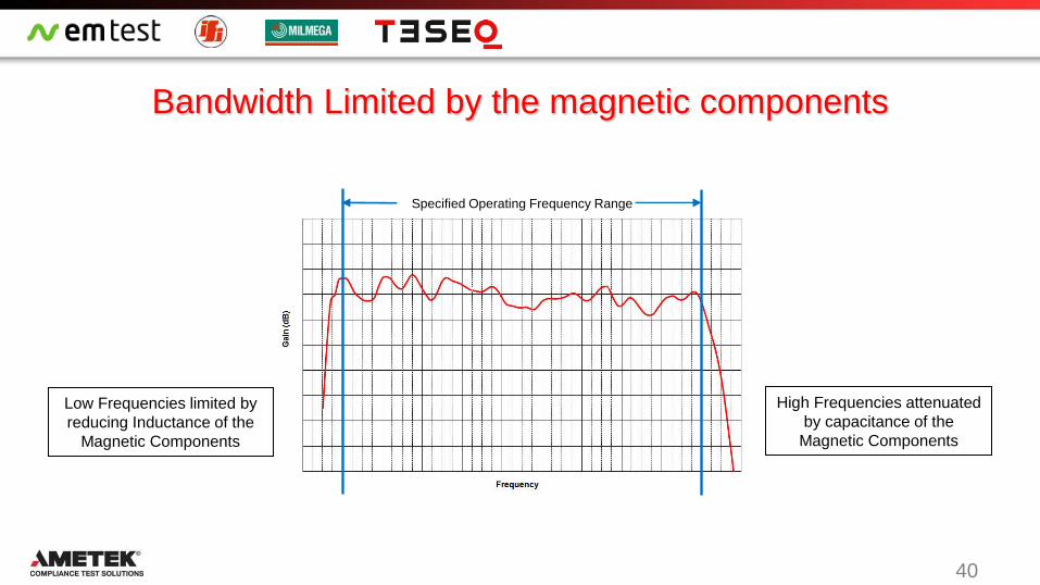
What limits the Bandwidth of an Amplifier
Amplifier designs require chokes and transformers
The lower the frequency the larger they need to be
At higher frequencies they start to become capacitive
The larger they are the more capacitive they become
So the lower and upper frequency is limited by the
selection of the magnetic components
40
Bandwidth Limited by the magnetic components
Specified Operating Frequency Range
High Frequencies attenuated
by capacitance of the
Magnetic Components
Low Frequencies limited by
reducing Inductance of the
Magnetic Components

41

42
Pout
Pin
CW
Maximum
Usable Power
Pulse Only CW/Pulse
Maximum
Usable Power
Maximum
Usable Power
Extrapolation

Conditions for Use at saturation
If the amplifier can produce enough power so that the field is calibrated CW at the full test level
Then there is no extrapolation and so any non linearity in the I/P-O/P curve has no effect
If it can be shown that the harmonics at saturation are better than -20dBc
The harmonics will not effect the test
Then the amplifier can be used at saturation
IMPORTANT NOTE
This only applies if system is calibrated at the full test level
Calibrating at a low CW level and scaling is not acceptable since the test level is above the linear region
43

Conclusion Amplifier selection will depend on a number of items
Antenna selection
Two narrow band antenna are more efficient and require less power but less
convenient to use
Wideband horn does not require changing during test but are less efficient
wideband horn with focusing lens more efficient but EUT size can be limited
Calibration method
Use of isotropic field probe more convenient but requires either
An amplifier capable of producing required power CW
A combined CW/pulse amplifier and scaling of results
Use of receive antenna and spectrum analyser
Can use pulse only amplifier but less convenient
Whatever your choice, Ametek CTS have a solution for you
44