pratt & whitney aircraft o, .o. o ::: ..-o - nasa · pratt & whitney aircraft is supplying...
TRANSCRIPT
SEMI-ANNUAL REPORT
NASA CR-54625
PWA-275Z
DEVELOPMENT OF COMPRESSOR END SEALS,
STATOR INTERSTAGE SEALS, AND STATOR PIVOT
SEALS IN ADVANCED AIR BREATHING
PROPULSION SYSTEMS
Prepared for
NATIONAL AERONAUTICS AND SPACE ADMINISTRATION
January 20, 1966
CONTRACT NAS3-7605
Technical Management
NASA Lewis Research Center
Cleveland, Ohio
Spacecraft Technology Division
D. P. Townsend
Project Manager
L. P. Ludwig
Research Advisor
Written by:
R. M. Hawkins
Assistant Program Manager
C. A. Knapp / ]
Program Manager
Approved by:
D. B. Waring ,__4(,
Development Engineer
UPratt & Whitney Aircraft o,_.o. _...o_:::_..-o_.._
E A S T H A R T F O R D • C O N N E C T I C U T
https://ntrs.nasa.gov/search.jsp?R=19660013058 2018-09-06T22:47:17+00:00Z

pRATT & WHITNEY AIRCRAFT PWA- Z7 52
PREFACE
This report describes the progress of work conducted between
29 June and 31 December 1965 by the Pratt & Whitney Aircraft Division
of United Aircraft Corporation, East Hartford, Connecticut on Contract
NA83-7605, Development of Compressor End Seals, Stator Interstage
Seals, and Stator Pivot Seals in Advanced Air Breathing Propulsion
Systems, for the Lewis Research Center of the National Aeronautics
and Space Administration.
Charles A. Knapp is Project Manager for Pratt _ Whitney Aircraft
for this program.
The following National Aeronautics and Space Administration per-
sonnel have been assigned to this project:
Contracting Officer - J.B. Vance
Contracting Officer - J.H. DeFord
Project Manager - D.P. Townsend
Research Advisor - L.P. Ludwig
Contract Administrator - T. 3. Charney
PA@E NO. ii

PRATT & WHITNEY AIRCRAFT PWA- ?.,75Z
SUMMARY
This report describes the work completed during the first six months
of an analytical, design, and experimental program directed at develop-
ing compressor end seals "_,stator interstage seals, and stator pivot seals
for advanced air breathing propulsion systems.
The objective of this contract is to achieve a means of increasing
compressor efficiency by providing compressor seals with significantly
lower air leakage rates than those currently in use while not incurring
undue penalties in reliability and weight.
The program involves a screening study of all potential types of seals
and a detailed feasibility analysis of those recommended for further evalu-
ation. This feasibility analysis is to be followed by design and procure-
ment of seals for rig evaluaton. Test rigs simulating advanced engine
construction, where applicable, will be procured for evaluation of these
seals under specified operating conditions. Mechanical Technology
Incorporated, under subcontract to Pratt & Whitney Aircraft, is to con-
duct an analytical program contributing to the feasibility analysis (Tasks I
and III) of the prime contract.
Pratt & Whitney Aircraft is supplying MTI with information required
to evaluate engine application of various seal concepts and is monitoring
MTI's efforts through periodic meetings, as required under terms of the
prime contract.
NASA approval was obtained for the screening studies of compressor
seal concepts required under Task I and Task III.
Work was initiated by MTI on a detailed feasibility analysis of four
compressor end seal, four stator interstage seal, and two stator pivot
seal concepts, with the major emphasis placed upon the analysis of pri-
mary seal faces.
A two and one half month extension of the prime contract was re-
quested by Pratt & Whitney Aircraft, as a result of a reschedule of the
MTI analytical effort. A supplemental agreement, effective 13 December
1965, was received from NASA extending the Period of Performance
from twenty-four (Z4) months to twenty-six and one-half (26 I/2) months.
Preliminary design work was initiated on Task II and Task IV test
rigs in which Task I compressor end seal and stator interstage seal and
Task III stator pivot seal experimental evaluation will be conducted.
Milestone charts are presented at the end of this report as Figures
87 and 88.
PAGE NO. iii

PR&TT & WHITNEY AIRCRAFT PWA-Z75Z
TABLE OF CONTENTS
D_ IkT_
PREFACE ii
SU_{MARY .°°111
LIST OF ILLUSTRATIONS vii
LIST OF TABLES xiii
INTRODUCTION
TASK I - CONCEPT FEASIBILITY ANALYSIS PROGRAMS
FOR COMPRESSOR END SEALS AND FOR STATOR
INTERSTAGE SEALS
MTI SCREENING STUDY
SUMMARY OF SCREENING STUDY
Concept I - One-Sided Floated Shoe
Concept II - Two-Sided Floated Shoe
Concept ILI- Thin Strip Plus Piston Ring
Concept IV - Thin Strip Plus C Diaphragm
Concept V
3
5
5
5
5
- Thin Strip Plus C Diaphragm (Radial)5
PRELIMINARY CONSIDERATIONS
Basic Leakage Rate
Film Thickness for Minimum Power Loss
Thermal Distortion
T racking Dynamic s
Primary and Secondary Seals
6
6
9
11
16
19
PRIMARY SEAL BEHAVIOR
Hydrostatic-Step Seal
Hydrostatic-Orific Compensated Seal
Hydrostatic - Labyrinth Seal
Hydrodynamic- Convergent Film
Hydrodynamic-Spiral Groove Seal
Hybrid Hydrostatic-Hydrodynamic Seal
Hybrid Hydrostatic Pad-Labyrinth Seal
20
20
24
27
30
32
33
34
COMPARISON OF PRIMARY SEAL CONCEPTS 34
PA(3£ NO. iv

PRATT8. WHiT,E¥ AiRCRAfT 9WA-- 2,752.
TABLE OF CONTENTS (Cont'd)
SECONDARY SEAL BEHAVIOR
Hydrostatic
B ell ow s
Piston Rings
Diaphragm
SCREENING OF SUGGESTED END AND INTER-
STAGE SEAL DESIGNS
General Discussion
Description of Seal Concepts
MTI FEASIBILITY ANALYSIS
SUMMARY OF FEASIBILITY ANALYSIS
Primary Seal Analysis
Seal Response
Seal Design
PRIMARY SEAL FEASIBILITY ANALYSIS
The Hydrostatic Step Seal
Spiral Groove Hydrodynamic Seals
Rayi eigh Step
Hydrostatic Orifice Compensated Seal
Hydrostatic Labyrinth Seal
Multiple-Pad Designs With Thin Strip Seal
Seal Response
SEAL DESIGN
Review of Concept V
Primary Seal For Hydrostatic Floated -
Shoe Designs
PRATT & WHITNEY AIRCRAFT PROGRAM
Approval of Screen Study Seal Concepts
Dimensional Variance Considerations
Analytical Program
TASK II - COMPRESSOR END SEAL AND STATOR
INTERSTAGE SEAL EXPERIMENTAL EVALUATION
Page No.
36
37
38
38
38
40
40
52
59
59
59
6O
6O
6O
61
77
82
82
90
91
98
I IZ
llZ
113
115
115
123
1 24
125
PAGE NO. V

PRAT_ & WHITNEY AIRCRAFT
PWA-Z75Z
TABLE OF CONTENTS (Cont'd)
TASK III - COMPRESSOR STATOR PIVOT BUSHING
AND SEAL CONCEPT FEASIBILITY ANALYSIS
MTI SCREENING OF VANE PIVOT SEAL DESIGNS
Screening
Screening Chart
MTI VANE-PIVOT SEAL FEASIBILITY ANALYSIS
PRATT & WHITNEY AIRCRAFT PROGRAM
TASK IV - PIVOT BUSHING AND SEAL EXPERIMENTAL
EVALUATION
PROGRAM SCHEDULE & MILESTONE CHART
APPENDIX A - FILM THICKNESS OPTIMIZATION STUDY
APPENDIX B - SOLUTION OF A HYBRID LUBRICATION
PROBLEM WITH RAYLEIGH STEPS AND
CYCLIC BOUNDARY CONDITIONS
APPENDIX C - CENTER OF PRESSURE, HYDROSTATIC
STEP- COMPUTER PROGRAM
APPENDIX D - PRESSURE AND FLOW, SPIRAL GROOVE
SEAL - COMPUTER PROGRAM
BIBLIOGRAPHY
REFERENCES
DISTRIBUTION LIST
Page No.
IZ6
IZ6
130
133
135
138
14Z
144
146
15Z
167
169
1 70
171
172
PAGE NO. vi

PRATT & WHITNEY AIRCRAFT P.WA-?., '752
LIST OF ILLUSTRATIONS
FigureNo.
2
4
5
6
9
10
11
12
13
14
15
16
17
18
Title
Leakage Rate vs Film Thickness for a TypicalSeal
Optimization of Compressor Power Due to
Leakage vs Drag Power Loss for Take-OffCondition s
Optimization of Compressor Power Due to
Leakage vs Drag Power Loss for CruiseConditions
Model for Simple Thermal Analysis
Calculated Temperatures for a Floated Shoe
Design
Calculated Temperatures for a Floated Shoe
Design Using Thermal Shunts
Distorted Seal Segment
Simplified One-Dimensional Vibration Model
for Seal Segment and Rotor System
Basic Primary Seal Concepts
The Hydrostatic Step Seal
The Hydrostatic Orifice Compensated Seal
Flow Through an Orifice
The Hydrostatic Labyrinth Seal
Flow Through a Double Knife Edge Labyrinth
Inclined Slider Seal Segment
Spiral Groove Hydrodynamic Seal
Hybrid Hydrostatic Step-Hydrodynamic Seal
Comparison of Seal Leakage Rates for Cruise
Operation
Page No.
I0
II
12
12
13
13
17
20
21
24
26
28
Z9
30
32
33
35
PAGE NO, vii

PRATT & WHITNEY AIRCRAFT PWA-2752
LIST OF ILLUSTRATIONS (Cont'd)
FigureNo.
19
2O
Zl
2Z
23
24
25
26
27
28
29
30
31
32
33
34
35
36
37
Title
Comparison of Load-Film Thickness Seal
Characteristic s
Types of Secondary Seal
_,ydrusL,_1,. Secondary Seal
Diaphragm-Type Secondary Seal
Load Curve-Hydrostatic Step, _1 = " 75
Load Curve-Hydrostatic Step, bl = " 5
Load Curve-Hydrostatic Step, _i = " 35
Load Curve-Hydrostatic Step, bl = " 25
Load Curve-Hydrostatic Step, bl = " 1Z5
Center of Pressure-Hydrostatic Step, _1
Center of Pressure-Hydrostatic Step, _1
Center of Pressure-Hydrostatic Step, _1
Center of Pressure-Hydrostatic Step, _I
Center of Pressure-Hydrostatic Step, _1
Dimensionless Film Stiffness-Hydrostatic
Step, b"l = " 125
Dimensionle ss Film Stiffne s s-Hydro static
Step, _i = "25
Dimensionless Film Stiffness-Hydrostatic
Step, E l = .35
Dirnensionless Film Stiffness-Hydrostatic
Step, _l = "5
Dimensionless Film Stiffnes s-Hydrostatic
Step, _'l = "75
• 125
.25
.35
.5
.75
Page No.
35
36
37
39
62
63
65
64
64
65
65
66
66
67
69
70
70
71
71
"" PAG_ NO. viii

PRATT & WHITNEY AIRCRAFT _). W._-- _-_ 75Z
LIST OF ILLUSTRATIONS (Cont'd)
Figure
No.
38
39
4O
41
42
43
44
45
46
47
48
49
5O
51
52
53
54
55
Title
Dimensionless Mass Flow-Hydrostatic Step,
b = . iZ51
Dimensionless Mass Flow-Hydrostatic Step,
b = .251
Dimensionless Mass Flow-Hydrostatic Step,
_i = .35
Dimensionless Mass Flow-Hydrostatic Step,
Dimensionless Mass Flow-Hydrostatic Step,
_i = .75
Hydrodynamic, Spiral-Grooved Seal
Dimensionless Flow vs Pressure Ratio
Spiral-Grooved Seal
Dimensionless Flow vs Pressure Ratio
Spiral-Grooved Seal
Coefficients K l and K 2 for Spiral-Grooved Seal
Hydrostatic Orifice-Load
Hydrostatic Orifice-Load
Hydrostatic Orifice-Load
Hydrostatic Orifice-Flow
Hydro static Orific e-Stiffne s s
Hydro static Orific e-Stiffne s s
Hydrostatic Orific e-Stiffnes s
Discharge Coefficient for Orifices. Experi-
mental Data to Generate this Curve were Taken
From Reference 3.
Hydrostatic Labyrinth-Load Curves
Page No.
74
75
75
76
76
77
8O
81
81
86
86
87
87
88
88
89
89
90
PAGE NO. ix

PRATT A WHITNEY AIRCRAFT PWA- Z 7 5Z
FigureNo.
56
57
58
59
60
61
62
63
64
65
66
67
68
69
70
71
72
73
LIST OF ILLUSTRATIONS (Cont'd)
Title
Angular Displacement of Thin Strip Seal
Double Orifice Primary Seal with SpiralGrooves
Cross-Section of a Double-Orifice Design
Double Pad Seals with Central Vent Groove
Tilting of Double Pad Seal
Dynamic Response Ratio
Dynamic Response Ratio - Enlarged Scale
Thin Strip Seal Ring
Diagram Showing Unwrapped Seal RingDeflection Curve and Rotor Contour
Force and Moment Diagram of a Seal Ring
S e gment
Force Distribution Across Tilted Seal
Twist of Seal Section
Thin Strip Radial Seal
Comparison of Stiffness for Orifice and Step
Hydrostatic Seals
Stiffness Flow Criterion vs Width Ratio
Compressor End Seal Concept Scheme A -Ref PWA Drawing No. L-67714 Ref MTI
Sketch-D- 2116
Compressor End Seal Concept Scheme C -
Ref PWA Drawing No. L-67714 Ref MTI
Sketch-D- 2134
Compressor End Seal Concept Scheme D -
Ref PWA Drawing No. L-67714 Ref MTI
Sketch-D- 2132
Page No.
91
94
95
96
97
98
99
99
100
101
103
104
IIZ
113
114
115
116
117
PAGE NO. X
PRATT&WHITNEYAIRCRAFT ,_'W'.A -- 7-, 757-d
LIST OF ILLUSTRATIONS (Cont'd)
Fi gur e
No.
74
75
76
77
78
79
80
81
82
83
84
85
86
Title
Compressor End Seal Concept Scheme E -
Ref PWA Drawing No. L-67714 Ref MTI
Sketch- D- Z 118
Stator Interstage Seal Concept Scheme A -
Ref PWA Drawing No. L-67713 Ref MTI
Sketch-D- 2116
Stator Interstage Seal Concept Scheme B -
Ref PWA Drawing No. L-67713 Ref MTI
Sketch-D- Zl 19
Stator Interstage Seal Concept Scheme C -
Ref PWA Drawing No. L-67713 Ref MTI
Sketch-D-Z134
Stator Interstage Seal Concept Scheme D -
Ref PWA Drawing No. L-67713 Ref MTI
Sketch-D-2132
Vane Pivot Seal Test Rig
Vane Pivot Seal Concepts
Single Bellows Seal
Single Bellows Seal, Sealol Design
Single Bellows Seal, Relocated Thrust Face
Stator Pivot Seal Concept Scheme A - Ref
PWA Drawing No. L-67563 Ref MTI Sketch
of 9-14-65 by H. Jones
Stator Pivot Seal Concept Scheme B - Ref
PWA Drawing No. L-67563 Ref MTI Sketch
of 9-i-65 by E. Belawski
Stator Pivot Seal Concept Scheme C - Ref
PWA Drawing No. L-67563 Ref MTI Sketch
of 9-5-65 by E. Belawski
Page No.
118
119
1 20
121
122
127
129
136
136
137
i39
140
141
PAGE NO. xi
PRATT & WHITNEY AIRCRAFT PWA-Z75Z
LIST OF ILLUSTRATIONS (Cont'd)
FigureNo. Title Page No.
87
88
89
Compressor Seal Development ProgramSchedule and Milestone Chart
Compressor Seal Development ProgramSchedule and Milestone Chart
Schematic of Leakage Area Slit Assumed for
Leakage Flow Computations
144
145
146
PAGE NO. xii

PRATT & WHITNEY AIRCRAFT 1_ _VV'.A -Z 75Z
LIST OF TABLES
Table No. Title Page No.
Comparison of Performance of Primary
Seal Concepts36
II Comparison of Secondary Seal Concepts 4O
III Matrix Chart for Seal Concepts HSS-I,
HSS-Z, HS-I, HS-Z, HS-3 and HS-4 43
IV Matrix Chart for Seal Concepts HS-5,
HS-6, HS-7 and HS-8 44
V Matrix Chart for Seal Concepts HD-1,
HD-Z, HD-3, HD-4, SG-1, and SG-Z 45
VI Matrix Chart for Seal Concepts HS-L-I,
HS-L-Z, HS-L-3, HS-L-4, VL and F-I 46
VII Matrix Chart for Seal Concepts F-Z, F-3,
D-I, D-Z, D-3 and D-3A 47
VIII Matrix Chart for Seal Concepts D-4, D-5,
and D- 6 48
IX Matrix Chart for Seal Concepts HS-9, HS-10,
and HS- 11 49
X Second Screening for End and Interstage Seal
C onc ept s 5O
XI Results of the Screening Study of End and
Interstage Seals 51
XII Comparison of Vane Pivot Seal Concepts 133
XIII Physical Dimensions - Compressor End
Seal 151
PA_E NO. xiii

PRAT'-F & WHITNEY AIRCRAFT PWA-2752
INTRODUC TION
High performance, modern multistage axial flow compressors built
with state-of-the-art features, incorporate several air leak paths which
are detrimental to compressor performance. Elimination or signifi-
cant reduction of these leaks would result in a compressor of higher
efficiency and possibly smaller size. Some typical areas of leak paths
with estimates of percent air loss and potential effect on compressor
perfornaance are:
%air loss effect on compressor efficiency
End Seal
I_nterstage Stator Seals
{ten stages)Vane Pivot Seals
(variable stator)
0.67o 1.07o0.9% 1.O7o
0.Z%per 0.2% per
stage stage
Increases in compressor efficiency are traditionally sought by
means of compressor geometry redesign. A few extra points in ef-
ficiency often mean the difference between a successful or an unsuc-
cessful engine design. These increases as a result of geometry change
are always very expensive and not always successful. On the other
hand, the losses to efficiency as a result of air leaks are strikingly
large and real gains are within reach at a relatively low cost. The
gains in efficiency however, must be balanced against any detrimental
effect that improved sealing may have on the engine, such as lower
reliability or increased weight.
This program will provide for a research, analytical, and test pro-
gram having as its goal the development of compressor end seals, stator
interstage seals, and vane pivot seals which exhibit lower air leakage
rates than those currently in use. This will be accomplished using
components of such Size, materials, and designs as to be considered
applicable to compressors for engines capable of supersonic aircraft
propulsion.
PAGE NO. 1

PRATT _ WH,TNEY A,RCRAFT PWA--Z75Z
TASK I - CONCEPT FEASIBILITY ANALYSIS
PROGRAMS FOR COMPRESSOR END SEALS
AND FOR COMPRESSOR STATOR
INTERSTAGE SEA LS.
A feasibility analysis program is being conducted on seals for
application in stator interstage and end seal systems. The first phase
of this program is a preliminary analysis and screening of various
seal concepts prior to the selection of concepts for the detailed feasi-
bility analysis. The analytical effort includes a comparison of the
selected concepts to current practice and all calculations, analyses,
and drawings necessary to establish feasibility of these selected con-
cepts. This analytical effort is subcontracted to Mechanical Technol-
ogy Inc. (MTI) of Zatham, New York and is being monitored by Pratt
& Whitney Aircraft as required under the terms of the NASA contract.
The screening study of compressor end seal and stator interstage
seal concepts conducted by MTI is presented in this section of the
report. The materialpresented in this section was prepared by Dr.
H.S. Cheng, Dr. D.F. Wilcock, and J. Bjerklie.
MTI SCREENING STUDY
Present jet engine designs employ labyrinth seals at the high pres-
sure end of the compressor and between compressor stages. Because
they must not rub severely during transient periods when temperatures
are changing, they operate with clearances as large as 0. 030 during
normal operation. As a result,, air flow through the seals is large,
and may amount to a loss of as much as 2 to 3 percent of engine power.
Reduction of this power loss resulting from seal leakage is the end
objective of the NASA program of which this study is a part. A design
is sought which will have one tenth, or less, of the seal leakage that
occurs when using the current labyrinth seal design approach. At the
same time it is desired that the new design be adaptable to current
engine design and manufacturing techniques, extremely reliable, light
in weight, and manufacturable by presently available processes.
Numerous concepts for new seal designs had been suggested. It
has been the objective of that portion of the study that is covered by
the screening phase of this report to analyze the potential performance
of each of these concepts and of additional concepts developed during
the study, and to select no more than four compressor end seal designs
and no more than four interstage seal designs for a further feasibility
analysis. The objective of the feasibility analysis is to develop two
PAGE NO. Z

PRATT &" WHITNEY AIRCRAFT PWA-Z75Z
designs of each seal to the point where prototypes can be built for
evaluation on a seal test rig.
Typical engine conditions were established to be used in comparing
seal concepts and in analyzing seal performance for the screening
study.
A seal diameter of Z7 inches was selected as "standard" for this
study, and current Pratt & Whitney Aircraft large engine configurations
have been used as the framework within which each design should
operate. Pratt & Whitney Aircraft experience indicates that the end
seal leakage rate is two to four pounds per second using labyrinth
seals, thus establishing the goal for a new end seal design as less than
0.4 pounds per second.
Additional information from Pratt & Whitney Aircraft has indi-
cated that for face seals, a total axial excursion, due to tolerance
build-up and thermal growth and transients, of 0.4 inches must be ac-
commodated. The FIR {Full Indicated Reading) for face wobble may
be as high as 0. 005 inches FIR, while the deviation of the runner face
from a plane can be expected to be no more than 0. 0005 inches FIR.
For cylindrical seals, the motions are larger, and the FIR may be aslarge as 0. 016 inches. An axial motion of 0.4 inches must also beaccommodated.
The authors wish to acknowledge the major efforts in the screening
study by Ralph Hooker and Henry Jones. Important contributions in
terms of understanding the relationship of the seal to the engine, and
the nature of engine parameters and tolerances, have been made by
C.A. Knapp, A.H. McKibbin, H.L. Northup, and R.M. Hawkins of
Pratt & Whitney Aircraft.
Summary of Screening Study
It was determined early in the study that analysis of the seal con-
cepts required separate examination of the primary and secondary seal
configurations. The primary seal is defined as that portion of the seal
adjacent to the high velocity mating surface. Since, in a close-running
seal, the primary seal must follow all motions of the runner surface,
it must be flexibly mounted. The means for flexibly mounting the
primary seal in such a way that leakage around it is prevented or
minimized is termed the secondary seal.
Since several basic types of primary seals can be combined with
each of several types of secondary seal, many combinations are pos-
sible. As a result, many concepts have been suggested for considera-
PA6E NO. 3

PRATT & WHITNEY AIRCRAFT PWA- 27 5 2
tion, sometimes several variations on a particular combination. It
has been helpful, therefore, to consider the primary and secondary
seal functions separately as a preliminary to the screening process.
Consideration of the basic processes at the high speed primary
seal interface leads to the following conclusions:
. To achieve the desired order of magnitude reduction in leakage
rate, the film thickness between runner and seal element
should be in the range of 0.5 to 1.0 mils.
The film thickness for minimum total power loss (compres-
sion power plus shear loss in the film) is in the same range.
. _At these film thicknesses, the major portion of the heat gen-
erated in the film must flow out through the runner structure
for eventual transfer to cooling air; the runner surface will
run about 100 F above the ambient.
. In order to minimize thermal distortion, the seal element
must be thermally isolated and may require thermal shunting
in its design in order to approach an isothermal condition.
. The Primary seal element must be light in weight in order to
permit tracking runner motions without diminishing film
thickness excessively. The key quantity is j" = n20_Zm/kf,
the ratio of dynamic load to film stiffness, which must be less
than 0.3 to avoid more than a 30 percent reduction in film
thickness for a disturbance amplitude three times the film
thickne ss.
, Because of problems of thermal growth and of tracking im-
perfect surfaces at a small separation distance, it appears
necessary that the primary seal be either segmented if it is
rigid, or highly flexible under the stress of reasonable fluid
film forces.
From an examination of several types of hydrostatic and hydro-
dynamic Primary Seals, it appears that hydrostatic design is required
to maintain the desired clearances, but that supplementary hydro-
dynamic action may assist by providing high film stiffness at the small
film thickness where hydrostatic stiffness falls off.
_An examination of secondary seal types indicates that the bellows
is impractical at the large diameters and for the large pressure dif-
PAGE NO, 4

PRATT &" WHITNEY AIRCRAFTPWA-2752
ferences involved. Hydrostatic, piston ring, and flexible diaphragm
constructions have sufficient merit to warrant further study in the
Feasibility Analysis Phase.
Following a detailed screening analysis based on considerations of
operational capability, leakage rate, seal weight, and reliability; five
concepts were selected for the Feasibility Analysis Phase. These are:
Concept I - One-Sided Floated Shoe
An axial or face seal, in which rigid primary seal segments are
held by the sealed pressure against a locating surface. Hydro-
static seal action is used at the primary seal surface and at the
locating surface. The segments are carried in a spring-floated
secondary seal carrier.
Concept II - Two-Sided Floated Shoe
A radial or circumferential seal, in which rigid primary seal
segments are pressure loaded against the rotating runner and
are held in place by hydrostatic seal action between locating
surfaces on either side of the segments.
Concept HI - Thin Strip Plus Piston Ring
An axial or face seal, in which the primary seal element is a con-
tinuous flexible ring (Rz-R>>t) with hydrostatic seal action at the
primary seal face. Moment balance is achieved by an integral
ridge carrying a piston ring for the secondary seal to a spring-loaded carrier.
Concept IV - Thin Strip Plus C Diaphragm
An axial or face seal similar to Concept III, except that the
secondary seal is accomplished by a C-shaped flexible diaphragm
instead of a piston ring between the thin strip and the spring-floated carrier.
Concept V - Thin Strip Plus C Diaphragm (Radial)
A radial or circumferential seal, otherwise similar to Concept IV.
This radial version of the thin strip plus C diaphragm design is
felt to be impractical because it appears impossible to attain a pressure-
balanced design, because of the compound curvature of the C diaphragm,
and because the thin strip must be discontinuous to accommodate
thermal expansion and must be sealed at the discontinuity.
PAGE NO. 5

PRATT & WHITNEY AIRCRAFT 1_ Wz_o - Z 75 _"
Preliminary Consideration
Basic Leakage Rate
Leakage of a high pressure fluid into a low pressure ambient
through the clearance between rotating and stationary machine surfaces
can be minimized by use of an orifice-type annular restrictor, by the
viscous resistance between surfaces separated by small clearances,
or by dry rubbing contact. The present jet engine compressor end
and interstage seals are of the labyrinth type which rely on an annular
orifice to resist the flow. Clearances of these seals are usually large
and leakage rates are high. The present study seeks to replace them
with an improved design having a substantially lower leakage rate.
Most of the seal concepts proposed for this study are of the vis-
cous type because sealing by viscous action can provide the largest
reduction in leakage rates. In order to determine the thickness at
which the sealing by viscous action becomes active, consider the
leakage rate through an infinitely wide gap with a finite leakage path.
The mass flow rate per inch of width can be derived as follows.
The simplified Stokes Equation gives
2a u
8 y2
Integrating
y = O,
y = h,
One obtains
1 ap
g. ax
u with respect to y, and using the boundary conditions
u = 0
U --- 0,
U 1 (0p)- 2g. _ y (y-h)
The mass flow ratio per inch of width becomes
h
m =f Pu dy
O
(1)
(la)
(lb)
PAGE NO. 6

PRATT _ WHITNEY AIRCRAFTPWA-Z752
Substituting (la) in (lb) and carrying out the integration,
hop a_._p_p
1Z p. 3x
Since the mass flow through any given section is constant,
dm- 0
dx
one obtains
(lc)
it follows that
(2)
Therefore, for an isothermal film where
h 3
p = p
(3)
For a parallel film where h is constant,
d 2
dx 2 (p2) 0(4)
Integrating pZ with respect to x between limits of 0 and b, and using
the boundry conditions
x=O,p =P2
x =b, p =Pl
the pressure distribution is given by
P = Pz
Pl x
1- 1 2 -F"
P2
1/2
(5)
The leakage rate can be obtained from Equations (1)
1TI h3 [ (pl)21- 24p.b 92P2 1 -
and (5) giving
(6)
PAGE NO. 7
PRATT & WHITNEY AIRCRAFT PWA-,2752
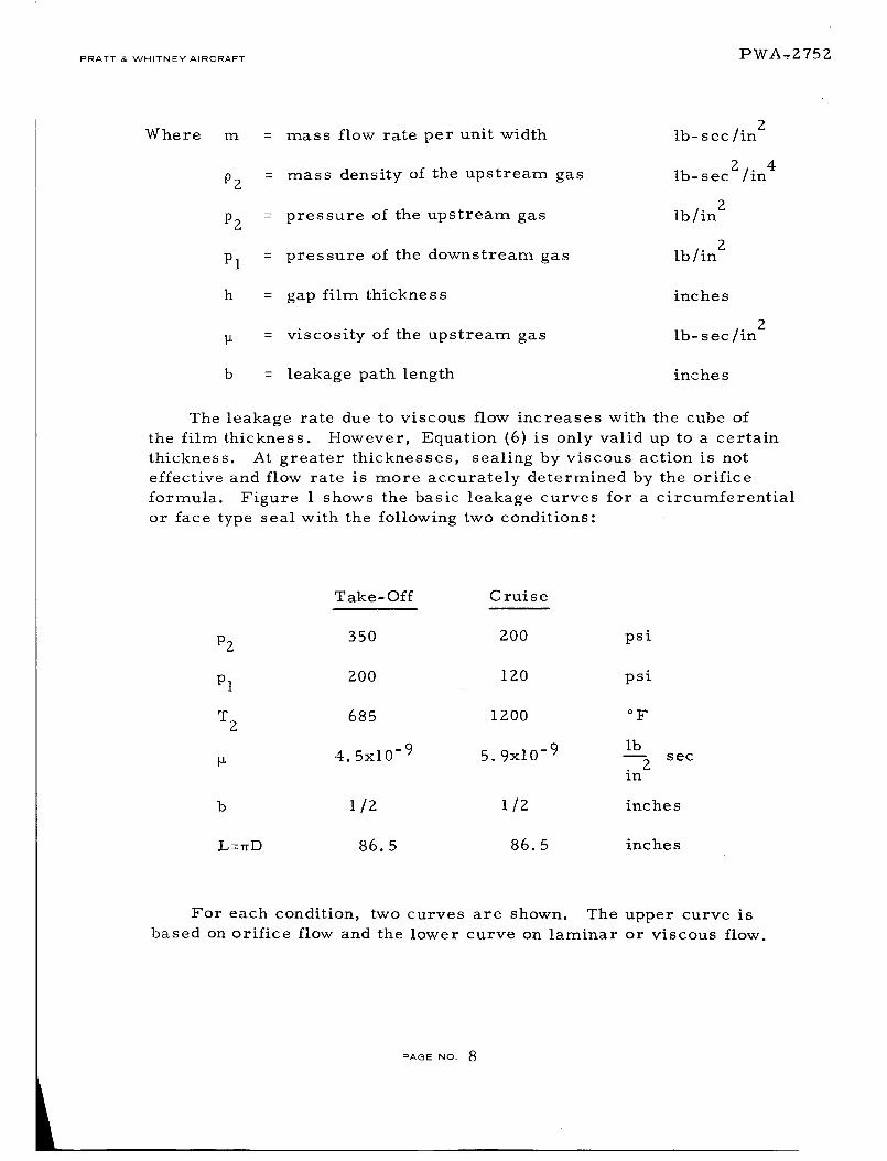
Where m = mass flow rate per unit width
P2 = mass density of the upstream gas
PZ = pressure of the upstream gas
Pl = pressure of the downstream gas
h = gap film thickness
= viscosity of the upstream gas
b = leakage path length
Ib- s ec/in 2
2Ib- sec /in 4
Ib/in 2
Ib/in 2
inches
Ib- sec/in 2
inc he s
The leakage rate due to viscous flow increases with the cube of
the film thickness. However, Equation (6) is only valid up to a certain
thickness. _At greater thicknesses, sealing by viscous action is not
effective and flow rate is more accurately determined by the orifice
formula. Figure 1 shows the basic leakage curves for a circumferential
or face type seal with the following two conditions:
T ake- Off C rui s e
PZ 350 200 psi
Pl Z00 120 psi
T 2 685 1200 °F
il 4.5x10 -9 5 9x10 -9 lb• _ sec
in
b 1/2 1/2 inches
L=wD 86.5 86.5 inches
For each condition, two curves are shown. The upper curve is
based on orifice flow and the lower curve on laminar or viscous flow.
PAGE NO. 8

PRATT _T_ WHITNEY AIRCRAF-I"
Figure 1
!.-.
IMO
ILl..I
100 1 I IL i J _ ' __-- , , , , , i iiIIII
_ ..... I tll I I, !-HI_l, = =""i ' IIIII
_____. I I 1ttli I I I JItlli i ' 1....__L_JlIII _ I [ ittli
I _1", '1 'l t I;__ tt,lt_l , . ,,'IIiLI/ iiitl I ! !11i! i [ i ill#[I
i rrl 1 ' I I I I!l_ i/i 11!"F- 'i ........ ".......... II
] I I I .... _ I i •
1111 , J_iI,...... Illi ' 1 J _ / X III
| 1 II I _'.....-_.ti_v i/t IJl_ _ . I I I II'_ " / III
/ i I i!II11 I II_ /f I IIII t l II ""*-o"'--,X1 lk" I1t
': , i,,,, /,,v'- ,, 1]1
llJtll I _ ,.,I I] I
i LAkll
_ i {11_ tl]
i I!1' ' '111
0._
ti
OI
ooll0OOO4
,
/ ' ' .--F--'-'IT-
L T..,_o,, c_, l
" . P 350
T I_(I'3°F i200oF
M. 45_10-9 LB 5EC 5e=lO -9 LB SECiIv 2 iee2
t I I I IIitl I t I t Iit[
0,(_ 01
Leakage Rate vs Film Thickness for a Typical Seal
PWA-2752
In the neighborhood of h = 0.001 inches, the flow is definitely
governed by the viscous flow and for h_ 0.01 inches, the orifice curves
are more representative. In the region where the two lines intersect,
the actual leakage will be slightly lower than is indicated by either
line. Note that viscous sealing becomes active at 0. 003 inches and
0. 0018 inches for the cruise and take-off conditions respectively.
Furthermore, to obtain a substantial leakage reduction compared to
the present seal, the new seal must operate in the region of about
0. 001. These two conclusions, although calculated from these simple
relations, are extremely significant in providing direction for the
screening study and in developing new concepts.
Film Thickness for Minimum Power Loss
If the compressor seal operates at a large film thickness, the
excessive leakage will require excess compressor power and reduce
engine efficiency. On the other hand, if the film thickness becomes
extremely small, the power loss due to seal frictional drag will go up
rapidly and become predominant. Consequently, it is desirable to
maintain an intermediate film thickness at which these power lossesare near a minimum.
PAGE NO. 9

PRATT & WHITNEY AIRCRAFT PWA -:-Z 752
Figure 2 shows the results of an optimization study for the take-off
condition. A detailed account of this study is presented in Appendix A.
Two sets of curves are represented in this figure; one for the end seal
and the other for the last interstage seal. For each set, there are
three curves. The rapidly decaying curve shows the seal drag loss
being inversely proportional to the film thickness and the right curve
is the calculated power loss due to the leakage of high pressure air.
In calculating the compression power loss it was assumed that none
of the energy in the leakage air would be recovered. By adding these
two power losses, one obtains the middle curve which shows a mini-
mum power loss at a film thickness equal to 0.0004 inches for the end
seal and 0.0011 inches for the interstage seal. Similar curves are also
shown in Figure 3 for the cruise condition. The optimized film thick-
nesses for this condition are slightly higher than for the take-off con-
dition; they are: 0. 0006 inches and 0. 0016 inches for the end and inter-
stage seals respectively.
3O
25
2O
o,
w
O
IC _
'COMPRESSORENDSEAL
COMPRESSIOI POWER
. !
I I/ '
OPTIMUMFILM FORINTERSTAGESEAL I
r I
/ '_'_--1"'_ / INTERSTAGESEAL
jj j_. COMPRESSION=POWER,
0.5 1.0 1.5 2.0FILM THICKNESS-hx 10-3
2.5
Figure 2 Optimization of Compressor Power Due to Leakage vs DragPower Loss for Take-Off Conditions
PAGE NO. 10

PRATT & WHITNEY AIRCRAFT PWA-2752
50
o,
w
O::z:
A
I_SSOR ENDSEAL
PRESSIONP_VER
!FILM FOR !
SEALDRAGPOWER j
COMPRESSORENDSEALi1
t iOPTIMUMFILM FOR iINTERSTAGESEAL j
00 0.5 1.0 1.5 20 25
RLM THICKNESS-INCHESx I0-5
Figure 3 Optimization of Compressor Power Due to Leakage vs DragPower Loss for Cruise Conditions
Thermal Distortion
Thermal Map - Assuming that there is no temperature gradient in
the circumferential direction, a steady-state analysis of the tempera-
ture distribution for a typical segment of a circumferential seal has
been performed using a discrete model. The geometry of this section
and the conditions used are shown in Figure 4. Results for a 1/Z-inch
square segment riding on a gas film of 0. 0006-inch film thickness are
shown in Figure 5. It is seen that a substantial thermal gradient can
be developed in the axial as well as radial direction due to the heat
generated by shearing of the air film. The same analysis was used to
investigate the effect of a thermal shunt to improve the thermal gra-
dient in the axial direction. As seen in Figure 6, the gradient in the
axial direction is reduced by more than 50 percent in the seal segmentas well as in the rotor.
PAGE NO. 1 1

PRATT & WHITNEY AIRCRAFT _C:)'r_ --2. 757-_
Figure 4
i
0125 It
1200 F
1200 F
INCONEL
0.5"
o..__o2" 1,F---_05'--
i °°°°6" I
0.0002'
1200 F
l0.0012" m = 0.027 LBISEC
,.25' t iINCONEL
1200F
_ 0 l 0 5 0 "
1200 F
Model for Simple Thermal Analysis
/
132E
o 1292
1326 1322 13'21
1316
1331 1316
132l ! a 1288 --=1248 1_4(_ x t_,41_
1_4 1309 1273n 0 Q
Figure 5
o 1200 %
Calculated Temperatures for a Floated Shoe Design
PAGE NO. 12

PRATT & WHITNEY' AIRCRAFT PWA-2752
Figure 6
/i112i_ 13B_
• 1241
I
,_3 ,3. i_l _"
|330 _1343 =129_'- U_D AS SHUIITS
I g BOZ1238 - 1304 - -
Calculated Temperatures for a Floated Shoe Design UsingThermal Shunts
Distortion of a Circumferential Seal Segment- When a seal ring
segment and the rotor drum are subjected to a high temperature
environment and heating from the shearing of the air film, the radius
undergoes considerable thermal distortion. It is important to determine
whether there still remains enough radius conformity between the seal
segment and the drum to insure an adequate hydrostatic gas film.
Figure 7 shows an exaggerated picture of the distorted drum and
seal segment under a steady-state condition.
Figure 7
_o
g
Distorted Seal Segment
d : R(I- coso/R I
PAGE NO. 13

PRATT & WHITNEYAIRCRAFT PWA. -2752
The film thickness h I at the end of a segment where the center
film thickness is h o, is given by
[ (hl _ 1 h + 1 - Cos _ C (7)Cos a o
R
where C is the difference in radii,
C = S- i<.
The rotor radius i_ will increase due to centrifugal force and
temperature increase. The segment radius will increase due to tem-
perature increase and thermal gradient bowing.
If we let:
Cm
5C
6t
= radial clearance as manufactured
= centrifugal growth,
= differential growth due to temperature and material
diffe rence
6b = radius increase due to thermal bowing
a o _ Cm - 6c + 6t + 6b (8)
Cos
The rotor centrifugal growth is estimated by
2
6 = 0.4p / -"'' "[Z_"_P,.
c \ 6O / _ (9)
where 0.4 represents an experience factor accounting for the restraint
of the hub (steel assumed).
The differential thermal growth is
5t = R (as Ts - ar Tr) (i0)
PAGE NO. 14

PRATT & WHITNEY AIRCRAFTPWA-2 752
The thermal bowing radial change is given by
R2 A T5b = a 7 (11)
where
E = modulus of elasticity, psi
a = thermal expansion coefficient of segment, in/in *Fs
ct = thermal expansion coefficient of rotor, in/in °Fr
T = surface temperature of segment, °FS
T = surface temperature of rotor, °Fr
AT = temperature change across t, °F
N = rotor speed, rpm
t = radial depth of segment, inches
Zp = mass density, lb.-sec -/in4
If we assume N = 8000, (Tr-T s) = Z5 F, t = 1/g, AT = Z0 F,
a = 7.5x10 -6, E = 30x106, R = 13.75, C m = 0.001, ho = 0.001
and using the same material for segment and rotor
283 /2wx8000x13.75\ 2 13 75
5 = 0.4 x " I.) x " = 0.0178c 386 \" 6"0 30x106
5 t = 7.5x10 -6 x 13.75 x 25 = 0.00257
5x10⁻⁶ 75)2 Z05b = 7. x (13. x 0.5
- 0. 0568
a 2
R 13.75- 0.1455 rad.
aCOS -- --
K0.9894
PAGENO. 15

PRATT & WHITNEY" AIRCRAFT P WA -- Z75Z
Inserting these values into Equation (3)
, [hl - 0. 9894 0.00 l + 0.0106 (0.001 - .0178 + 0.00Z6 + 0.0568)]
= 0.00146
and
h I - ho = 0.00046
The above calculation shows clearly that bowing of the segment
due to thermal distortion caused by radial temperature gradients is a
major cause of film thickness variation under a segment, and that these
effects can be large in proportion to the desired film thickness. Under
these conditions, heating will be concentrated at the smaller film
thickness regions and may further aggravate the film distortion. Whether
this effect will result in thermal instability will be examined during the
Feasibility Analysis Phase.
Distortion of a Seal Ring - The thermal distortion of a complete ring is
different from that of the segments. Under an axial temperature gra-
dient, a free ring will bend thermally into a spherical surface and for,
a ring of 1/2 inch square section, a = 7.5x10 -6, AT = 20, the rotation,
6 , of the cross section due to the axial thermal gradient is found to be
-6I_/_Z_T_ 13.75 x 7.5xi0 x 205= = I/2 = .0041 tad.
This degree of angular rotation (4 mils per inch) would cause rub-
bing contact for the one rail film thickness desired for the seal. There-
fore, either the temperature gradient must be made much smaller, for
example by thermal shunting, or the tendency to rotate must be coun-
tered by the angular moment stiffness of the air film in the seal.
Tracking Dynamics
One of the most important aspects of seal performance is con-
formity or tracking of the seal ring or seal segments to the irregular
motion of the rotor due to the runout, initial warping and elastic or
thermal distortion of the runner. To determine the exact motion of
the seal ring in the presence of these irregular excitations, it is neces-
sary to carry out a vibration analysis for the segment considering it as
PAGE NO. 16

PRA__WH,TNEY A,RCRA_ PWA-2752
a rigid body capable of moving in all unrestrained directions. For a
continuous seal ring, it is necessary to treat the problem as an elastic
ring resting on the gas film which may be considered as an elastic
TT ......... _-k_ v .L tJ .L Cl t, 4.1JJ.4, .I..L,t V _.O_L V _.. d "l- r'_
be considered in the screening stage; it is more useful to consider a
simplified analysis to indicate whether the film stiffness is adequate to
allow the seal ring to follow the rotor face. To this end, a simplified
one-dimensional vibration model for the seal segment and rotor system
is chosen and shown in Figure 8.
ot t---
"I
;EAL
do
Figure 8 Simplified One-Dimensional Vibration Model for Seal Segmentand Rotor System
The equation of motion of this system is
ms + Cs + (ks+kf)(S-So)= (d-do)kf (lla)
where
kS
kf
= stiffness of the seal back-up springs
= stiffness of the fluid film
m = mass of the seal
C = combined viscous damping constant
a t ' at Z
PAGE NO. 17

PRATT & WHITNEY AIRCRAFT _[z)WA - _.'75 Z
The term (d-do) represents the motion of the rotor face which
includes the runout, wobbling, initial warping, or waviness. Of course,
(d-do) is a function of time and, in general can be represented mathe-
matically by a Fourier series as follows:
00
d-d = _ . f Cos n_0t (llb)O _ n
n=o
To determine the response of the seal element within the frame-
work of linear vibration theory, the motion of the seal element, s-s o ,
when subjected to a single component, fn cos n00t, can be put into the
form,
s-s = A e0 n
incot, (11c)
where A is the complex amplitude.n
Substituting (llc and llb) into (lla) and collecting the terms
in_0tcontaining e p one obtains
An 1
f k s mn20_ 2n --_ n¢oc i
(lld)
It follows that the magnitude of A can be expressed asn
(lle)
For the seals considered in this investigation, the value of k s is
in the order of 2 lb/in/in of seal segment, and the value of kfwill be
shown later to be in the neighborhood of 10,000 lb/in/in. Consequently,
the term ks/k f can be ignored in Equation (lle). Furthermore, the
damping of a fully floated segment is believed to be small so that the
damping term can be ignored in estimating the response. Using these
arguments, Equation {lle} becomes
PAGE No. 18

PRATT _,_ WHITNEY A_RCRAFT PWA-2752
fn
_C
i - con
(llf)
where
2 2mn
n kf
The satisfactory tracking of the seal ring can be measured by the
ratio, 6/h, where 6 is equal to IAnl - fn representing the differencebetween the seal motion and the rotor motion and h is the fluid film
thickness. In terms of the quantity ¢o*, the ratio 5/h can be writtenas
Anl - fn 5
h h
f
- tl 9h 1 0_*
f (*)n- , (llg)
h 1 c0
When this ratio is below 0.3 (a design experience factor), the
tracking is considered to be satisfactory. This criterion is used later
in the screening study for all proposed seal concepts. Rewriting (llg),
5
* h 1
f f8 n n-- +-- i +--h h 5
(llh)
Primary and Secondary Seals
Examination of the requirements for a low-leakage seal and of the
dynamic as well as transient motions it must accommodate shows that,
in addition to the primary seal behavior at the high speed interface,
one must also be concerned with some form of flexible or adjustable
support for the primary seal. Thus, motion of the primary seal
requires that a secondary seal be made to avoid static leakage behind
the primary seal. By definition (in this report) the primary seal sup-
porting and sealing structure is termed the secondary seal.
_,_G_ No. 19

PRATT & WHITNEY AIRCRAFT P WA ;" ?-, 757.t
These requirements for both small running clearance and dynamic
motions due to runout, irregular surfaces, and thermal and elastic
growth, dictate that the primary seal must itself be flexible for small
motions. For these reasons, rigid one-piece primary seals appear
impractical. Rather, the primary seal must either be very flexible
or it must be segmented to accommodate small motions.
Primary Seal Behavior
Five basic primary seal concepts and two hybrid concepts have
been considered. The configurations of these concepts are shown in
Figure 9. Descriptions and principles of these concepts are discussed
in the following sections. Analyses for these concepts are also made
based on the assumption of an isothermal and parallel film thickness.
Figure 9
HYDROSTATIC -LABYRINTH
HYDRODYNAMIC
STEP SEAL
[_ ORIFICE COMPENSATED
SPIRAL GROOVE
....I
HYDROSTATIC - HYDRODYNAMIC
HYDROSTATIC PAD- LABYRINTH
\ /
Basic Primary Seal Concepts
Hydrostatic-Step Seal
In this concept, a step in the sealing surface is located at the high
pressure, (p2) s side of the seal as shown in Figure i0. As the gap
decreases, the resistance to flow in the smaller film increases and
causes the pressure to build up in the larger film, providing a positive
stiffness for the gas film. Several pressure profiles across the seal for
various film thicknesses are depicted in Figure i0.
PAGE NO. 20

PRATT & WHITNEY AIRCRAFT
GEOMETRY
PRESSURE
LOAD
__ __.]-Fp21 1 I 0,,/ I I_,_,
P
__,_%_ LOW h
P2! "_ _ INTER k
Pt _ --=..3&_ X
W_ARGE ( h2-hi)W
LARGE b2/b
2/b
,,, h
PWA-2752
STATIC
STIFFNESS
b (h2-hl
Figure 10 The Hydrostatic Step Seal
The pressure distribution in the step seal can be determined by
matching the flow through the step as follows. If the intermediate
pressure at the step is designated by Pi, the flow in the upstream
section can be expressed (see Equation (6)), by
h23 [ Pi 2
m = 24_b 2 P2P2 1- _2(12)
and likewise, in the downstream section by
h3 [ </zipm - Z41_bl pipi 1 -(13)
PAGE NO. 2. 1

PRATT & WHITNEY AIRCRAFT PWA-g752
where
m
h Z ,h I
P2'Pl
bl,b Z
P2' Pi
= flow rate per unit circumferential
length
= film thicknesses of the upstream and
downstream sections
= upstream and downstream pressure
= widths of the sealing surface (see Fig. 9)
= densities at the upstream and downstream
entrance
Ib- sec/in Z
inches
Ib/in z
inches
2Ib-sec "/in4
Equating (12) and (13), one obtains
Pi = P2
\h2! + :
\_/ 1
1/2
(14)
LettingPi
r. ° -
:J Pj
and following equation (5),
the pressure in the upstream section becomes
_.)x ] :/_-P = PZ I - (1 - rig _ (15)
and likewise, the pressure in the downstream section can be expressed
as
E2= - - (16)P P2 ri2 i2 rlZ b I
PAGE NO. 22

PRATT & "VVHITNEY AIRCRAFT PWA-2752,
I
Defining the dimensionless load W by
W =_: (p - pl ) dx
(Pz - Pl) b(17)
and substituting (15) and (16) into (17), one obtains
m
W = [ i1 [b2i -(I-ri2 )2 x - dx
(I - rl2)b ]o ! _ rI2 ,
Integrating with respect to x, one obtains the following expression forthe load parameter
1W -
1 - rlZ
b Z Z (ri2 + ri2 +
-- 3 (ri2 + i) - rl
The actual load per inch of length of seal is, therefore,
w : b(Pz-Pl)w (19)
Once the intermediate pressure is determined by Equation (14),
the leakage rate and load can be readily calculated from Equations (13)
and (18). The film stiffness can be obtained by differentiating the load
parameter with respect to the film thickness. One may define a gas
film stiffness, Ks, as the change of average film pressure with respect
to the film thickness, and it can be expressed as
PAGENO. 23

PRATT ,_ WHITNEY AIRCRAFT PWA'2752
KS dh 1 dh 1 P2 - Pl) (20)
dW
The derivative dh I
the Feasibility Analysis.
is derived in the Hydrostatic step section of
The variation of the load and stiffness with respect to the step geom-
etry can be seen qualitatively in Figure I0. Optimization of the step
geometry as well as other primary seal concepts will be carried out in
the detailed feasibility analysis.
Hydrostatic-Orifice Compensated Seal
The cross section of an orifice-compensated seal is shown in
Figure II. High pressure air is fed into a groove of width (d) through
a series of orifices of radius (a) and spaced at a distance (_). Either
the upstream gas or an external gas supply can be used as the high
pressure source. The pressure in the groove increases with a de-
crease of the film thickness because of the lower flow rate and conse-
quently lower pressure drop across the orifice, and thereby provides
a positive film stiffness. The pressure distribution at different levels
of film thickness is seen in Figure ii.
GEOMETRY
PRESSURE
"- xc--JI. o3LOAO
W L ;ARGE o
l_ K s _ KS
P LOW h
STATICINTER h STIFFNESS
P2 q
P2 = P3
- \\ .oPl _I_ • X
ml, h
i lid
Figure 11 The Hydrostatic Orifice Compensated Seal
PAGE NO. 24
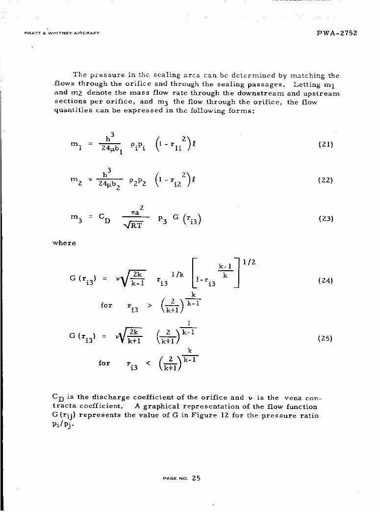
PRATT & WHITNEY AIRCRAFT PWA-2752
flows through the orifice and through the sealing passages. Letting m l
and m2 denote the mass flow rate through the downstream and upstream
sections per orifice, and m 3 the flow through the orifice, the flow
quantities can be expressed in the following forms:
h 3
m. - piPi (l-r, 2_f (21)1 24t_b 1 \ _i /
h3 (I- 2)1_ (22)m 2 - 24_b 2 P2P2 ri2
2
m3 = CD waq_ P3 G (rig) (23)
whe re
G (ri3) : 2_kZ--_k1 1/k I1v ri3 - ri3
k
for ri3 > (_1) -_-_- 1
1
k
for ri3 < (_)k-1
1/2
(24)
(25)
C D is the discharge coefficient of the orifice and v is the vena con-
tracta coefficient. A graphical representation of the flow function
G(rij ) represents the value of G in Figure 12 for the pressure ratio
Pi/Pj.
PAGE NO. 25

PRATT & WHITNEY AIRCRAFT Iz)WA - ?_ 75 _.
Ii.In
o_=E
O
04O_I
II.
ILl
U o3
oO.2
II.I
--I
Z
0 Ol
zILl
Figure IZ
l i
[ 1
ii
l L0.2 0 a 0 # o._ o.6 , o7
(ORIFICE PRESSURE RATIO) 2 = (P1/Ps) 2
Flow Through an Orifice
\
For continuity of flow,
m I = m Z + m 3 (26)
Substituting (21), (22), and (23) into (Z6), one obtains
241_b (_1)(ri2- rl- (b-'_-) (1 - ri22)
2
Tra P3
C D G (ri3) {27)q RT
which can be solved graphically or numerically for the intermediate
pressure Pi- It should be pointed out that the units of the gas constant,
R, are inZ/sec 2 °R (R for air is 2.47 x 10⁵ inZ/sec 2 °R}.
Once Pi or ri2 is determined, the leakage rate can be readily cal-
culated by (21), and the dimensionless load as defined by
s b (P-Pl) dx
= o (28)(pz-pl) b
PAGE NO. 26

PRATT I" WHITNEY AIRCRAFTPWA-2752
can be readily integrated in the same manner as the hydrostatic step
seal, using Equations(15) and (16). The resulting formula is
W
-I-
b \ 1 - r12 )
+ I C" I ]bl ri2 li + rli + 1
b 1 - r12 rli+ 1 - rli(Z9)
The gas film stiffness can be readily obtained by numerical differen-
tiation of W with respect to h and it can be expressed by
s = dh = -- Z - p (30)
The variations of the load and stiffness with respect to changes of the
geometrical dimensions "a" and "d" are also qualitatively depicted
in Figure 11.
Hydrostatic-Labyrinth Seal
The hydrostatic-labyrinth seal relies on a series of knife edges to
restrict the flow as shown in Figure 13. The clearance between the
knife edge and the opposite ring is controlled by feeding a high-pressure
gas into the center of the seal ring. Like the orifice-compensated seal,
this high-pressure gas could be taken directly from the upstream gas
or from a separate source. Two pressure profiles are shown in Figure
13 for two different film thicknesses. At a low film thickness, the high
pressure region extends further towards the exit end and gives a higher
load capacity. The pressure at the center cavity between the knife
edges can be determined in the same manner as the orifice-compensated
seal except that the viscous passages are now replaced by orifice
restrictors.
PAGE NO. Z7

PRATT & WHITNEY AIRCRAFT PWA --Z 7 5 g
GEOMETRY
PRESSURE
P3
P2-
P2
2o
4- b2 -_ d --_- m --,-
h
-Y LOAD
WHIGH o
h
STATIC KS
STIFFNESS
Pl _o
Figure 13 The Hydrostatic Labyrinth Seal
Letting the flow through the upstream knife edges be denoted by
m2, through the downstream knife edges by m I , and through the ori-
fice by m3 , the expressions for m I, m2 and m 3 can be written as
Ch_p2 P<_-Z 1m Z - g (31)
Ch_P6 PI-_6 1m I - g (32)
m3 = CD P3 G (33)
Where the function G represents the flow through the orifice
(shown in Figure IZ). The flow function g represents the mass flow
through the double knife edges and is shown in an empirical curve in
Figure 14. C is the discharge coefficient of the labyrinth. Again
the units for R are inZ/sec 2 °R.
PAGE NO. Z8

PRATT _, wfIITNEY AIRCRAFT PWA-2752
Figure 14 Flow Through a Double Knife Edge Labyrinth
Matching the flow, one obtains the following equation,
C D G + g
(34)
14
knife edges can be determined by
Equation (34) can be solved graphically by using Figures 12 and
for P6' and once P6 is known, the intermediate pressures between
P4 _
P2 2
1 +
P5 _
P6 2
(35)
(36)
P_E No. 29

PRATT & WHITNEY AIRCRAFT WWA-'2752
With P4' P5 and P6 known, the dimensionless load becomes
W
#ob(ppl)dx(p2p,)blib2(- 1 - rlZ _ r4z-rl
Z + Y r6z +--_- r5z-rl
and the gas film stiffness can be calculated by differentiating W with
respect to h numerically according to the following expression,
m
dW
Ks -- --dh (P2 " Pl) (38)
The effect of changing the orifice on the load and the static stiffness is
qualitatively shown in Figure 13.
Hydrodynamic -Convergent Film
Figure 15 shows a typical segment of a hydrodynamic seal operat-
ing on the principle of an inclined slider. During operation, a con-
vergent film is formed and gives rise to circumferential and radial
pressure profiles as shown in Figure 15.
GEOMETRY
8 P
W h I
P_ P2 INTER h I
PRESSURE
LOAD
HIGH h i
K
ST 'F - N' SSIIL Ihi / • _ h i
(,3"7)
Figure 15 Inclined Slider Seal Segment
PAGE NO. 30

PRATT & _h/HITNEY AIRCRAFT PWA-2752
In order to estimate the film thickness at which hydrodynamic
pressure becomes significant, a solution to the pressure is obtained
based on the short bearing equation for an incompressible fluid; the
additional load generated by the hydrodynamic action can be calculated
by
1 1 6_U /\2 1 /h2-hl//\
aw = 3-_ (l-r) P2 _-'_1) _ )T ' "h-_(39)
Assuming that the hydrodynamic effect upon the leakage is negligible,
the leakage across each segment can be obtained by integrating the local
leakage for differential element according to Equation (3). The result-
ing expression for each segment of length _ is
h13_
m - 96_b P2 P2- 1
(40)
The static stLff_ess can be estimated by
d_) ZaW (Pz- Pl) (41)
Using the following data:
= viscosity = 5.96 x 10 -9
U = surface velocity = 10,000
b = width of the seal segment = 0.5
: length of the seal segment : 2.0
h 1 = smaller film thickness = 0. 0005
h Z = larger film thickness = 0.001
Pl = 200 psi
PZ = 350 psi
AW = 0, 0378
lbsec
Zgn
in/see
riches
inches
inches
inches
PA6E NO. 31

PRATT & WHITNEY AIRCRAFT PWA - _ 75Z
the leakage and static stiffness were found respectively to be 0.0506 Ib/
sec and Z2,600 ib/in 3. In Figure 15, the variation of load and static
stiffness with respect to h I is also depicted qualitatively. Note the
extra load capacity at extremely low film thickness which indicates the
desirability of using hydrodynamic action as a protection from bottoming.
Hydrodynamic-Spiral Groove Seal
The hydrodynamic action in this seal concept can be achieved by a
band of spiral grooves located at the low pressure side of the seal. By
virtue of the viscous action of the gas, the groove geometry, as oriented
in Figure 16, creates a pumping action which increases the resistance
of the gas flow from the high pressure to the low pressure side. _At a
higher film thickness, the pumping is ineffective, so that the seal
operates like a step seal as indicated by the pressure profile "b" in
Figure 16. The pumping action becomes effective as the film gradually
decreases, in that there may exist a film thickness where the pressure
gradient in the smooth surface region becomes zero, so that perfect
sealing will result as indicated by the pressure profile "c". Further
decrease of the film thickness will cause the groove region to act as a
compressor and produce negative leakage.
GEOMETRY
PRESSURE
i h2
P2
_----b2
P2
f fh DIRECTION OF ROTOR
VELOCITY
PI
(D) LOW h (PUMPING IN,NEGATIVE LEAKAGE)
C) INTER h (NO FLOW)
_ _,_B) INTER h (NO HYDRODYNAMIC EFFECT)
LOAD
=, h
KS
STATICSTIFFNESS
Figure t6 Spiral Groove Hydrodynamic Seal
PAGE No. 32

PRATT & WHITNFy AIRCRAFT PWA-2752
It is desirable to determine the film thickness at which no flow will
take place• For the velocity of 10,000 in/sec, a groove width of 1/4
inch anu a gas v_s_ .... y of 5 96 In-9 (lb. sec)/in 2 this film thickness
was found to be 263 microinches. This indicates that the spiral groove
seal can be made effective only at an extremely small film thickness.
Numerical programs are available to determine the performance of
the spiral groove seal and this calculation will be made in the detailed
feasibility analysis.
Hybrid Hydrostatic-Hydrodynamic Seal
This concept combines the design of a hydrostatic-step seal and a
hydrodynamic seal. The geometry of this seal concept is shown in
Figure 17. The sealing is accomplished by a narrow gap at the low
pressure side. On the high pressure side, intermittent pockets are
provided to form a series of circumferential step bearings. At a higher
film thickness, the pressure generated by the hydrodynamic step bear-
ing is negligible, and the seal operates like a step seal. When the film
thickness decreases, the hydrodynamic action becomes effective and
the extra load capacity protects it from bottoming.
GEOME TRY
PRESSURE
P2
PI r
L OVt h
INTER h
_,_ _ P OPEN
_
LOAD
W
STATIC
STIFFNESS
Figure 17 Hybrid Hydrostatic Step-Hydrodynamic Seal
-- h
-- h
To date, there is no exact analysis to predict the performance of
this geometry, but a rough estimate of the load capacity can be made by
using the infinite step bearing theory. It was found that an additional
mean pressure of 30 psi can be obtained at h = 0. 0005 inches based on
the infinite theory. For a finite seal geometry, the load capacity will
be considerably less than this estimate.
PAGE NO. 33

PRATT & WHITNEY AIRCRAFT PWA-Z 752
A detailed calculation of the performance by modifying the
present computer program for the partial arc bearing will be carried
out for further comparison with other seai concepts.
Hybrid Hydrostatic Pad-Labyrinth Seal
The last primary seal concept is also a hybrid type which con-
sists of a labyrinth seal with intermittent hydrostatic pads for the
purpose of controlling the clearance of the labyrinth and at the same
time providing the necessary dynamic stiffness for satisfactory track-
ing. The basic performance of this seai concept is quite similar to
that of the hydrostatic-labyrinth seal with the exception that the response
of this seal will be more favorable than the plain labyrinth seal on
account of the higher dynamic stiffness.
The analyses developed for the orifice compensated seal and
hydrostatic-labyrinth seal can be directly used here to estimate the"
load, static stiffness and leakage of this hybrid concept.
Comparison of Primary Seal Concepts
Load and leakage curves were calculated for a typical geometry
of the hydrostatic-step, the hydrostatic-pocket (also called orifice-
compensated), and the hydrostatic-labyrinth seal concepts. These
results are plotted in Figure 18 and 19. The hydrostatic-pocket con-
cept appears to have the best stiffness. The leakage curves shown in
Figure 18 are only for the cruise condition. For the hydrostatic-step
and the hydrostatic-pocket concepts, the leakage in the thin film
region is governed by laminar flow, and in the thick film region it is
governed by orifice flow. The leakage for the hydrostatic-labyrinth
seal is always of the orifice type and it is represented by a single
curve in which the leakage is directly proportional to the film thick-
ness.
Table I shows a comparison of all primary seal concepts based on
their leakage, film thickness leveI, tracking capability, and reliability.
An individual rating is given to each of these considerations; some of
the reasons on which the rating is based are listed after the table. The
total ratings of these concepts indicate that no one basic primary seal
concept has a clear-cut superiority over the others. The hybrid con-
cepts appear to be slightly more favorable than the basic concepts. The
close comparison in the total ratings suggests that a more detailed
analysis of each concept is necessary in order to make the final selec-
tion of the primary seal concept for the test rig.
RAGE NO. 34

PRATT & _/HITNEY AIRCRAFTPWA-Z75Z
ORIFICE FLOW COND,_TION _:{)R_
0.OO*
L_S_WTH
HYDROSTATIC STEP
_" HYDROSTATIC POCKET
O OI0 0001 0.01 0 J
I_I (INCH}
Figure 18 Comparison of Seal Leakage Rates for Cruise Operation
W
0.9
0.8
I HYDROSTATIC- POCKET
Q6
_HYDROSTMIC
J
_ ,,,,,,r_,
0.5
- LABYRINTH
-__....,HYDROSTATIC-STEP
0.001 0.002 0.003 0.004 0.005 QO06 0.007 0.008
hi(INCH)
Figure 19 Comparison of Load-Film Thickness Seal Characteristics
PAGe NO. 35

PRATT & WHITNEY AIRCRAFT PWA-2752
TABLE I
COMPARISON OF PERFORMANCE OF PRIMARY SEAL CONCEPTS
(Based on Segmented Design)
Step Seal
Orifice
Compensated
Hydrostatic 0. 126
Labyrinth
Hydrodynamic 0.02
Spiral 0.0
Groove
Hydrostatic 0.01
Hydrodynamic
Hydrostatic 0, 126
Pad Labyrinth
(E) - End
(1) Inter
6
Leaka !e ib/sec.
Cruise) (Take-Off)
0. 044 0.25
0. 038 0.22
O. 350
0.1
0.0
0.05
0.30
Film
Thickness
h in.
0.001
0.001
0.001
0.0005
0.0003
0.0003
0.001
Radial or
Z Axial lb
Track. in 3
7 g/h=0.24(E)
:2. o (i)
7 6/h=O. 0561E)
=o. 5] (l)
4 Very Low
9 6/h=0. 128(E)
:].4 (i)
9 5/h:0.21(E)
:2.2 1[)
lO 6/b:O. ZliE)=z. 2 (i)
4 b/h=0.22(E)
=2.0 (I)
Amplitude of seal vibration relative to the rotor
based on a rotor radial amplitude of 0. 016 TIR
_ ._ Tol ...... _ Final
Angular _ _ to Dirt _ Rating
Tracking n. Stability _< _t Rubbing _ (E) (I)
5 Low 2 Low 2 Low 2 1" 09 .02
I
7 Low 2 Low 2 Low 2 I. 13 .04
2
1 Very l High 8 Medium 5 05 . 05
Low
6 Medium 5 Very 1 Low 2 18 . 03
1 Low
5 Medium 5 Very 1 Low 2 15 . 03
I Low
5 Medium 5 Very 1 Low 2 16 . 033
1 Low
5 Low 2 Medium 5 Medium 5 32 . 07
1
Secondary Seal Behavior
The secondary seal concepts suggested for screening study can be
classified into four types as shown in Figure 20. The operation and
principle of each concept are described in the following paragraphs.
HYDROSTATIC --_-- RINGPISTON
BELLOWS
DIAPHRAGM
Figure 20 Types of Secondary Seal
PAGE NO. 36

PRATT .& WHITNEY AIRCRAFT
PWA-Z75Z
Hydrostatic
As shown in Figure 21, the principal feature of this concept is that
both sides of the seal segments are floated frictionlessly by hydrostatic
bearings. This action allows the seal segments to track the rotor mo-
tion freely.
Vertical forces are balanced by limiting the horizontal surface over
which PZ acts, and by applying the downstream pressure Pl to the two
shoulders. Horizontal forces are likewise balanced by the insertion of
the low pressure zone on the right-hand vertical face, and the high
pressure zone on the lower left-hand vertical face. Moment balance
may be achieved by adjusting the shoulder width b 4 and the shoulder
heights d and g. Each vertical face has a restoring force generated by
a hydrostatic step. While orifice compensation could be used, the step
construction appears more simple and straightforward in this case.
The clearances of these secondary sealing surfaces should be held
at 0. 0003 to 0. 0005 inch in order to keep the secondary leakage at a
minimum.
/P2
_3[ I
I i
I i
i--I
I II
GEO.ETR 1 ,
bF"
PRESSURE
--_ ,,b-- h4, I
--''-
d
"h4 1
Figure Z1 Hydrostatic Secondary Seal
PA6E NO. 37

PRA:: : WHn'NEY AJRCRAFT PWA-2752
Bellows
The bellows has a unique feature as a secondary seal, namely that
it acts as a seal as well as a spring. But so far, successful applica-
tions of bellows have been limited to smaller diameters, low tempera-
tures and moderate pressures. When the requirements become more
severe, the walls of the bellows may buckle under the pressure unbal-
ance between sections. Advice from Sealol, Inc., indicates also that
the necessary radial dimension is about two inches, a figure too large
for compact design. For these reasons, it is doubtful that a satisfactory
bellows can be designed for the present seal application.
Piston Ring
The piston ring and spring type of secondary seal construction is
the most commonly used design, at least in all face-type seals. Either
one or two piston rings can be used to provide secondary sealing between
the frame and a carrier on which the primary seal ring is mounted.
The piston ring is usually pressure-balanced to yield low friction across
the secondary sealing surface. Minimizing frictional force is important
since it may prevent satisfactory tracking of the runner under rotor
vibration.
Successful results have been reported by Pratt & Whitney Aircraft
in using the piston and spring design on jet engine main bearing seals.
No great difficulty is anticipated in manufacturing large diameter piston
rings for the compressor and interstage seals, so that the piston ring
design is a strong contender among the list of secondary seal concepts.
Diaphragm
The function of a diaphragm secondary seal is very similar to that
of the bellows. It is a flexible connector between the primary seal and
the carrier. Figure Z2 shows a typical schematic of a primary seal
mounted on a "U" shaped diaphragm. The flexibility of the diaphragm
allows the primary seal strip to conform to any movement of the rotor
caused by runout, transverse or axial vibration, and thermal expansion.
Free body diagrams showing the forces acting on the seal strip and the
diaphragm can be found in the lower half of Figure 22. The primary
sealing surface is illustrated as the hydrostatic-step type and is located
on the bottom of the strip. The pressure in the sealing area is balanced
by the full pressure acting on the top face of the strip extending to where
the diaphragm begins. In the horizontal direction, the forces acting on
the strip are balanced by a tension member anchored to the frame. This
tension member is located in such a way as to insure a moment balance
of all forces on the strip.
PAGE NO. 38
L

PRATT &. _/HITNEY' AIRCRAFT PWA-2752
GEOMETRY
//// /
DIAPHRAGMTENSION
-I ........... i. MEM,,ER
""'PRI,,,,,Y SE,,.STR,P
W
II
z_o
PRESSURE
T
IIIW
[T + tap
Z_p
Figure 22 Diaphragm-Type Secondary Seal
The diaphragm seal is applicable for both circumferential and face
seals. For circumferential applications, it may be necessary to pro-
vide radial slots in the diaphragm to increase its flexibility. Secondary
foils will be overlayed between slots to prevent leakage through slots.
For radial face seals, a single-piece diaphragm will be governed mainly
by the bending stress caused by a maximum movement of the primary
seal and the direct stress produced by the hydrostatic pressure.
The one-piece diaphragm appears to be attractive from the stand-
point of leakage, friction, and simplicity but the slotted diaphragm with
secondary foil will definitely introduce complications to the seal sys-
tem. From the standpoint of dimensional stability and reliability, the
diaphragm secondary seal is not desirable because of its extremelythin structure.
Table II shows a qualitative comparison of a11 secondary seal con-
cepts. On balance, the hydrostatic and piston-ring types appear more
practical than the flexible-diaphragm seals.
PAGE No. 39

PRATT & WHITNEY AIRCRAFT PWA-2752
TABLE II
COMPARISON OF SECONDARY SEAL CONCEPTS
Dimensional Total
Leakages r Friction r Simplicity r Stability r Reliability r Rating
Hydrostatic Medium 5 Very Low 9 Simple 9 Medium 5 Medium 5 3.24
Piston Medium 5 Medium 5 Simple 9 Medium 5 Medium 5 1.8
Diaphragm Low 7 Medium 5 Medium 5 Low 2 Low 2 .224
Bellows Very 9 Very Low 9 Medium 5 Very 1 Very 1 . 130
Low Low Low
r = Individual rating
Screening of Suggested End and Interstage Seal Designs
General Discussion
Altogether, 34 seal designs have been collected for screening.
These seal designs include those contained in the request for proposal
and in the Pratt & Whitney Aircraft proposal, those suggested by Stein
Seal Co., and those conceived by MTI during the course of the pre-
liminary screening study.
A brief scanning of the suggested designs revealed that emphasis
had been placed on the primary seal design. In most cases, the bellows
were used as a symbol for the secondary seal and little or no considera-
tion was given to the secondary seal friction and balancing. Subsequent
preliminary analyses of film thickness level, leakage rate, heat gen-
eration, and thermal distortion all indicated that secondary sealing
design is of utmost importance. It has a major influence upon the
static and dynamic performance, particularly for a segmented design.
For this reason, the designs conceived later during this investigation
have given more considerations to the secondary seal design.
PAGE No. 40

PRATT &,WHITNEY AIRCRAFT PWA-2752
Each design has been given a code number according to the type of
primary seal concept. The abbreviations used are the following:
HSS - Hydrostatic-Step
HS - Hydrostatic-Pocket
HD - Hydrodynamic
SG - Spiral Groove
HSL - Hydrostatic-Labyrinth
VL - Vortex Labyrinth
D - Diaphragm
F - Foil
In this screening study these designs have been compared against
the following criteria:
Criteria Rating
Leakage rate, both primary and secondary 7.
Z.
o
4.
5.
Compens ation ability
a. Primary seal tracking 2
b. Secondary seal friction and balancing Z
c. Thermal distortion Z
Gas film stability Z
Dimensional stability 2
Reliability
Fail safe ability
Tolerance to start,
ao
b. stop and high speed rub
c. Tolerance to foreign particles
d. Off-design operation (tracking), at
I. take -off
2. idling
3. windmilling
4. response to rapid maneuver of aircraft
PAGE NO. 41

PRATT & WHITNEY AIRCRAFT _C)'W'.,_--_- 75Z
Each design is given an individual rating from 0-I0 for each crite-
rion. _Avalue of 5 is considered average, above 5 favorable and below
5 unfavorable.
Since many of the criteria are essential, in that a low rating must
rule out a design poor in that respect, the total rating has been formu-
lated as a multiplicative rather than an additive combination of the in-
dividual ratings. The most important factors are given an exponent
of Z. Following this approach,
YI
(r )TOTAL R.ATI:,G = _'o i ei
where
e i = exponents for r i
ri = individual rating
n = number of criteria considered
The result of this screening is expected to yield sufficient informa-
tion to select four designs for further detailed feasibility study. The
weight, space and costing factors were not included in the screening
criteria. These factors are considered as secondary at this stage and
would have been only if the screening study based on the primary es-
sential criteria yielded insufficient reason for selection.
The screening is accomplished in two stages. In the first stage,
careful considerations and individual ratings are given to each seal
concept against the first half of the screening criteria. Results of
this screening study are shown as matrix charts in Tables I11 through
IX. The first ten interstage and end seal concepts are selected for
further screening against the second half of the screening criteria.
Results of the second screening are tabulated in Table X. Based on
the results of the second screening, the first four designs of the end
as well as interstage seal concepts are selected and recommended for
further feasibility study. A summary of these results is shown in
Table XI.
PA6E NO. 4Z

PRATT & WHITNEY AIRCRAFT
4
HSS- 1
CONCEPT
Type of Primary Seal
Type of Secondary Seal
Type of Seal Ring Construction
Hydrostatic- Step (Segmented)
Bellows or Piston
Face or Circumferential
LEAKAGE RATE a. Primaryb. Secondary
PRIMARY SEAL TRACKING
SECONDARY SEAL FRICTION
AND BALANCING
0.004 Ib/sec. 70. 005
6 .084 (End, Face) 7
h .65 (Inter, Face) Z
Poor 3
THERMAL DISTORTION Can be controlled by
segment length.
ELASTIC DISTORTION Can be controlled by
segment thic kne s s.
GAS FILM STABILITY Stable 8
DIMENSIONAL STABILITY
INTERM/EDIATE RATING (End)
(.Inter)
/
Low tolerance to wear 5
tSelected
for further
screening

TABLE IH
I%£ATRIX CHART FOR SEAL CONCEPTS HSS-1, HS
HSS-Z HS- 1
PLATEIII! hi
Hydrostatic-Step (Segmented)
Spring & Hydrostatic
Face
ROTOR
SPRIN_
Hydrostatic -Face Hydro,
Bellows Hydro,,
Solid Ring Solid
0.044 7 0. 038 8 0. 038
0.05 0.0 0. 001
6 0.084 (End) 7D ----
h O. 65 (Inter) Z
Friction Very High 1
Same as HSS-I 5
6 .02-. (End) 9 6 .02
= . 16 (Inter) 6 _ = . 16
Friction Low, 1 Frictio
but balancing Balanci
is difficult difficul
for bellows.
Thermal coning 5
is severe but
can be compen-
sated by elastic
deformation.
Coning
Same as HSS-1 6
Stable 8
Low tolerance to wear 5
I. 753 x 105
0.211 x 10⁵
Twist of
section is
severe, can
be controlled.
Stable if 6
orifice is
properly
designed.
1. 038 x 105[O. 69Z x 105]
tSelected
for further
screening
6 Small
Stable
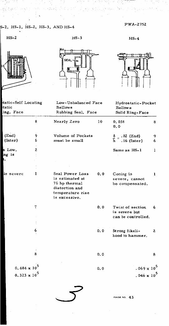
PWA-Z75ZS-Z, HS-I, HS-Z, HS-3, AND HS-4
HS-Z
S
HS-3 HS-4
_isl _ _
tatic-Self Locatingtatic
Face
Low-Unbalanced Face
Bellows
Rubbing Seal, Face
Hydrostatic- Pocket
Bellows
Solid Ring-Face
(End) 9(Inter) 6
Low, Z
is
Nearly Zero
Volume of Pockets
must be small
l0 0. 038
0.0
5 . OZ (End)
h .16 (Inter)
Same as HS-1
8
96
is severe 1 Seal Power Loss
is estimated at
76 hp thermal
distortion and
temperature riseis excessive.
0.0
0.0
Coning is
severe, cannot
be compensated.
Twist of section
is severe but
can be controlled.
0.0 Strong likeli- Z
hood to hammer.
0. 484 x 105
0. 323 x 105
0.0
0.0 • 069 x 10 5
•046 x 105
PAGE NO. 43
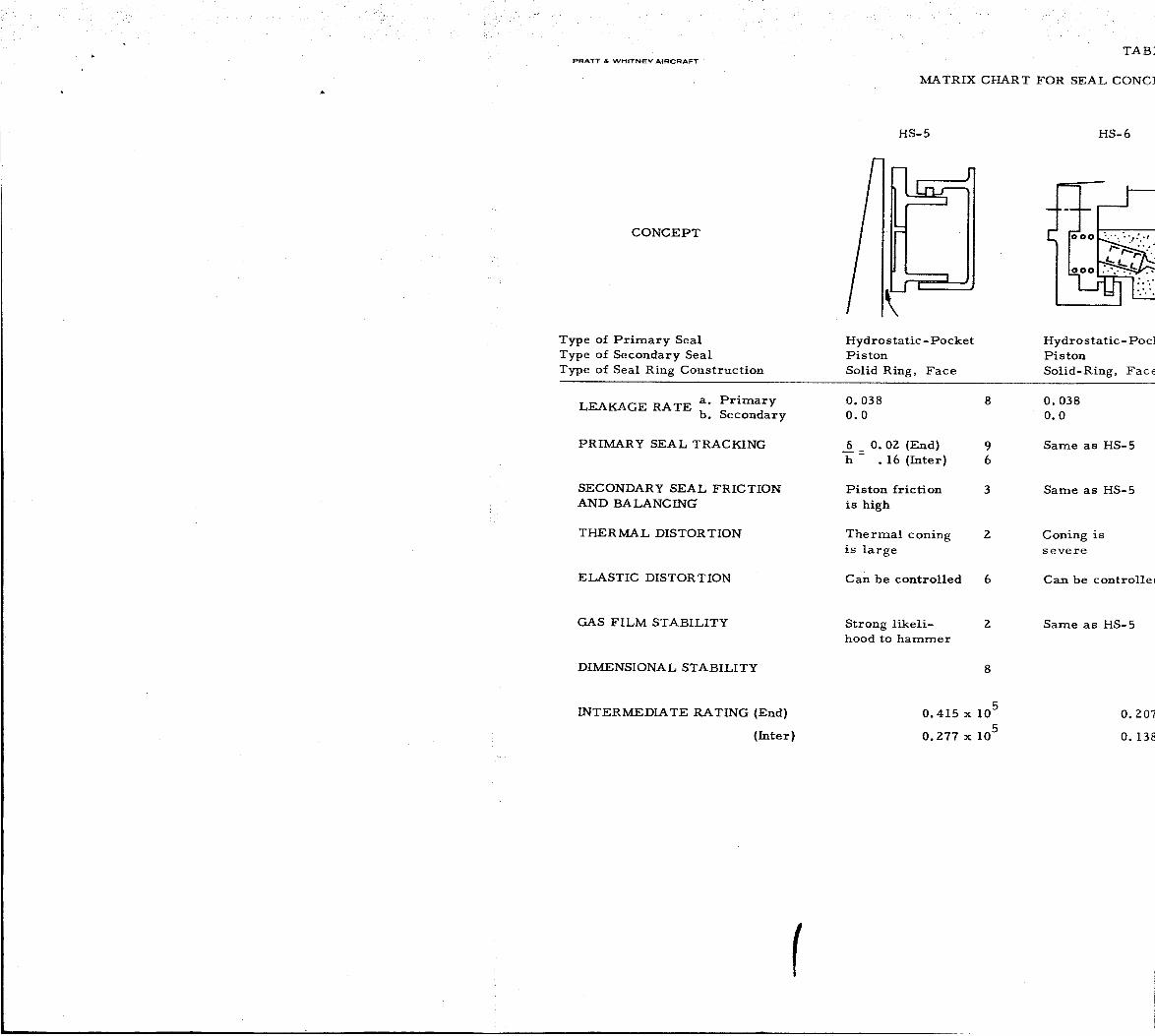
PRATT & WHITNEY AIRCRAFT
TAB]
_TRIX CHART FOR SEAL CONC}
CONCEPT
HS-5
/
HS-6
[
!
Type of Primary Seal
Type of Secondary Seal
Type of Seal Ring Construction
Hydro static- Pocket
Pi s ton
Solid Ring, Face
LEAKAGE RATE a. Primary 0. 038 8b. Secondary 0.0
6 0.0Z (End) 9
h . 16 (inter) 6
PRIMARY SEAL TRACKING
Piston friction
is high
SECONDARY SEAL FRICTION
AND BALANC IN_
Thermal coning
is large
THERMAL DISTORTION
ELASTIC DISTORTION
3
Z
Can be controlled 6
Hydrostatic- Pod
Piston
Solid-Ring, Face
0. 038
0.0
Same as HS-5
Same as HS-5
Coning is
severe
Can be controlhc
GAS FILM STABILITY
DIMENSIONAL STABILITY
Strong likeli- Z
hood to hammer
Same as HS-5
INTERMEDIATE RATING (End)
(Inter)
0.415 x 10⁵
0. Z77 x 105
0.207
o.13s
f

i •
PTS HS-5, HS-6, HS'7, AND HS-8
PWA-Z752
HS-7 HS-8
Hydrostatic-Externally Press.Piston
Solid Ring
u
III
Hydrostatic-Externally Press.
Piston
Solid Ring, Face
0.07 6 0.07 6
0.0 0.0
Same as HS-5 9
9
Piston friction is
very high
Coning is severe I
Same as HS-5 9
9
Same as HS-5 6
Coning is severe 1
6 Twist of seal ring
can be controlled
Very strong likeli-
hood to hammer
8
x 10 5
x 10 5
8
0. Z07 x 105
0. Z07 x 105
Twist can be 6
controlled
Same as HS-7 Z
8
0. 311 x 105
0.311 x 10⁵
pAee No. 44

PRATT & WHITNEY AIRCRAFT
MATRIX CH/
CONCEPT
Type of Primary Seal
Type of Secondary Seal
Type of Seal Ring Construction
HD- 1
_PRINGS t_ k
Hydrostatic -Shoe
Bellows
Segmented, Face
Hydr
Dry
Segrr
LEAKAGE RATE a. Primaryb. Secondary
PRIMARY SEAL TRACKING
SECONDARY SEAL FRICTION
AND BALANCING
THERMAL DISTORTION
ELASTIC DISTORTION
GAS FILM STABILITY
DIMENSIONAL STABILITY
INTERMEDIATE RATING (End)
(Inter)
0.0Z at 0.0005" 9 0.02
0. 005 at 0. 0003" 0.00
5 .04 (End)
h .3Z (Inter)
Friction is low
balancing for
bellows is
sensitive
Can be con-
trolled by vary-
ing length of
s egments
8 5
5 h 1
Severe but can
be controlled
1 Fricl
high
Stable
5 Same
1.38 x 1050.86Z x 105
tSelected
for further
screening
6 Less
8 Stabl

TABLE V
iRT FOR SEAL CONCEPTS HD-I, HD-Z, HD-3, HD-4, SG-I, AND SC
HD-2 HD-3 HD-4
_dynamic - Shoe
Lub
ented, Circum.
Hydrodynamic-Shoe
Dry Rub
Segmented, Face
I !
I l
I
Hydrostatic -Hydro
Dry Rubbing
Segmented, Circur
!fat O. 0005" 9
at O. 0003"
1Z (End) 6
10 (Inter) 0.0
ton very 0.5
0.0Z at 0. 0005"
0. 005 at 0. 0003"
5 .04 (End)
h •32 (Inter)
Friction very
high
0.5
0.01 at 0. 0003"
0.0
6 .18 (End)
h 1.5
Friction very
high
as HD- 1 5 Same as HD-Z Severe but can be
controlled
severe 7 Less severe 7 Small
Stable Stable
0.605 x 10⁵
0.0 0. S05 x 105J0.504 x 105
tSelected
for further
screening
0.405
O.C
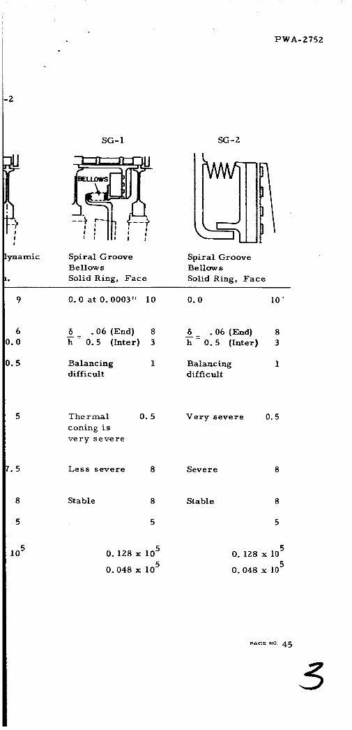
PWA-2752
!
!
!
_aamic
SG- 1
Spiral Groove
Bellows
Solid Ring, Face
SG-Z
I
i
Spiral Groove
Bellows
Solid Ring, Face
0.0 at 0.0003" I0 0.0 I0'
5 .06 (End) 8
= 0.5 (Inter) 3
Balancing 1
difficult
6 .06 (End) 8
h 0.5 (Inter) 3
Balancing 1
difficult
5 Thermal
coning is
very severe
0.5 Very severe 0.5
5 Less severe 8 Severe 8
8
5
Stable Stable
105 0.128 x 10⁵
0.048 x 10⁵
0.128 x 10⁵
0.048 x 10⁵
PAG_ NO 45

PRATT & WHITNEY AIRCRAFT
M_AT]
HS-L-I
CONCEPT
Type of Primary Seals
Type of Secondary Seals
Type of Seal Ring Construction
Hydrostatic -LabyrinthBellows
Solid Ring, Face
LEAKAGE RATE a. Primaryb. Secondary
PRIMARY SEAL TRACKING
SECONDARY SEAL FRICTION
AND BALANCING
THERMAL DISTORTtON
ELASTIC DISTORTION
0. II at 0. 001"
0.0
Tracking poorbecause of low
dynamic stiffness
Balancing
difficult
Face coning is
less severe
Less severe 8
GAS FILM STABILITY
DIMENSIONAL STABILITY
Most likely un-
stable but hammer-
ing amplitude mightbe small
INTERMEDIATE RATING (End)
(Inter)
.0576 x 105

TABLE VI
LIX CHART FOR SEAL CONCEPTS HS-L-I, HS-L-Z, HS-L-3; HS-L-4,
HS-L-2 HS-L-3 HS'
ydr os tatic- Labyrinth
iston
}lid Ring, Face
Hydrost. Pocket-LabyrinthBellows
Solid Ring, Face
Hydrost. Pc
Pi s t on
Solid Ring,
11 at . 001" 5
0
esponse is poor 1
_cause of low
gnamic stiffness
iction is high 6
hermal coning
less severe
it cannot be
)mpensated
6
ess severe 8
0. 108 at 0.001" 4
0.0
With hydrostatic pads 5
dynamic stiffness is
adequate
Bellow balancing is 1
difficult
Thermal distortion
can be significant
4
Less severe 8
0. 126 at 0.(
0.0
Response is
because of ]
dynamic sti
Friction is
Same as HS
Less sever_
tree as HS-L-I 3 Same as HS-L-I 3 Same as HS
.346 x 105 • 153 x 105
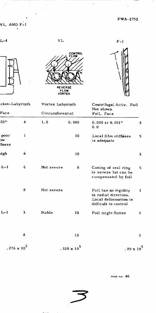
PWA-Z752
L-4 VL F-I
CONTROL
REVERSEFLOW
VORTEX
\\
,cket- Labyrinth
Face
Vortex Labyrinth
Circumferential
Centrifugal Activ. Foil
Not shown
Foil, Face
01" 4 I. 0 0. 005
poor
3W
_uess
,igh 6
I0
I0
0.038 at 0.001"
0.0
Local film stiff,4ess
is adequate
L-1 6 Not severe 8 Coning of seal ringis severe but can be
compensated by foil
L-I 3
Not severe
Stable 10
Foil has no rigidityin radial direction.
Local deformation is
difficult to control
Foil might flutter
10
• Z76 x 105 .320 x 105 • 09 x l05
PAGe NO. 46
IIIII

PRATT & WHITNEY AIRCRAFT
hCA_
CONCEPT
Type of Primary Seal
Type of Secondary Seal
Type of Seal Ring Construction
F-Z
--iI
k____
U
Foil-Hydrostatic
Hydrostatic
Solid Ring, Face
I
II
Foil- S]
Foil
Circun
a. PrimaryLEAKAGEb. Secondary
PRIMARY SEAL TRACKING
SECONDARY SEAL FRICTION
AND BALANCING
0.038 at 0. 001"
0. 005 at 0. 0003"
Local film stiff-
ness is adequate
Very low
O. 0Z al
0.0
Same z
Frictic
tolerat
THERMAL DISTORTION
ELASTIC DISTORTION
GAS FILM STABILITY
Coning is severe
but can be com-
pe ns ate d
Foil local de-
formation is
difficult to
c ontr ol
5
Foil might flutter 3
Sere re
compe;elastic
tion
Foil lo
format
difficu_
control
Foil m
DIMENSIONAL STABILITY
INTERMEDIATE RATING (End)
(Inter)
• 16Z x 10 5
• 16Z x 10 5

[:,
RIX
TABLE VII
CHART FOR SEAL CONCEPTS F-Z, F-B, D-l, D-Z, D-B, and D
F-3 D-; D-2
!
I}
11 i i i_
)iral Groove
Iferential
, #
Hydrostatic-Porous Pads
Diaphragm
Solid Ring, Circum.
,¢
Hydrostatic
Diaphragm
Segmented, Circum.
O. 0005"
s F-2 5
n is 8
le
but is 5
Lsated bydeforma-
:al de- 1
on is
t to
9 0.019
0.0
5 = .06 (End) 8
h .5 (Inter} 3
Friction is verylow but side
thrust is not
balanced
Severe but it is
compensated byelastic deforma-
tion
Severe but con-
trollable
5
0.019 9
0.0
6 .06 (End} 8
h .5 (Inter) 3
Friction is
medium side
pressure is
not balanced
Severe but it
is compensated
by elastic defor-
mation
Severe con-
trollable
ght flutter 3 Stability can be
controlled by
pore size
Stable
5
• 162 x 105
.162 x 105 .81 x 105• 304 x 105
tSelected for
further screening
• 648 x 105
•225 x 105

PWA-Z75Z
-3A.
D-3 D-3A
w.x.J_Z/ / / / / /'v--r'/ / i
II :hHydrostatic -Hydrodynamic
Diaphragm
Segmented, Circum.
Same as D-3
with Piston
Ring replacing
Diaphragm Ring
Hydrostatic -Hydrodynamic
Piston
Segmented, Circum.
0. 044 at 0. 001" 7
0. 015 at 0. 0003"
5 .Z5 (End) 5
= Z. 1 (Inter) 0
Friction is low 9
balancing is good
0. 044 at 0. 001" 7
0. 015 at 0.0003"
Same as D-3 5
0
Friction is high 6
balancing is good
Can be controlled
by length of
segments
Can be controlled
by length of
segments
Less severe 8 Less severe
Stable 8 Stable 7.5
0.5 £5
• 50Z x 105
0
• 3 15 x 10 5
0
pAse No. 47

* PRATT & WHITNEY AIRCRAFT
CONCEPT
TABLE VII
MATRIX CHART FOR SEAL CON(
Do4
Type of Primary Seal
Type of Secondary Seal
Type of Seal Ring Construction
Hydrostatic
Piston- Diaphragm
Flexible-Ring, Face
a. PrimaryLEAKAGE RATE
b. Secondary
0. 038 at 0. 001"
0. 005 at 0. 0003"
PRIMARY SEAL TRACKING 6 .02 (End)
h . 16 (Inter)
SECONDARY SEAL FRICTION
AND BALANCING
Friction can be
high. Balancing
is good
Hydros
Diaphra
Flexibl
0.038 a
0.01 at
Same a z
Frictioz
Balanci
THER MA L DIS TOR T ION
ELASTIC DISTORTION
GAS FILM STABILITY
DIMENSIONAL STABILITY
1st SCREENING RATING (End)
(Inter)
Severe but can be
compensated
Severe but con-
trollable
Stable
3.45 x 10⁵ 12.30 x 10⁵
tSelected for
further screening
Same a
Same a_
Stable
/

PWA-Z75Z
EPTS D-4, D-5 and D-6.
D-5 D-6
iatic Hydrostatic
gin-Hydrostatic Diaphragm- Bellows
:-Ring, Face Flexible-Ring, Face
! 0. 001" 8 0. 038
0. 0005" 0.0
D-4 9 Same as D-4
6
is low Z Friction is low
*g inadequate Balancing is
difficult for
bellows
D-4 5 Same as D-4
9
6.
D-4 6 Same as D-4
8 Stable
I, 15 x 105 10.767 x 10⁵
tSelected for
further screening
8
5
0. 575 x 105
0. 383 x 105
PAGe NO. 48

PRATT & WHITNEY AIRCRAFT
MATRIX CHART FOB
CONCEPT
Type of Primary Seal
Type of Secondary Seal
Type of Seal Ring Construction
HS_9
Hydrostatic
Fully Floating Hydrostatic
Segmented, Circumferential
LEAKAGE RATEa. Primary
b. Secondary
PRIMARY SEAL TRACKING
SECONDARY SEAL FRICTION
AND BALANCING
0. 044 at 0. 001"
0.03 at 0.0003"
5 .06 (End)
= . 5 (Inter)
Friction is low
Balancing is good
THERMAL DISTORTION
ELASTIC DISTORTION
GAS FILM STABILITY
DIMENSIONAL STABILITY
1st SCREENING RATING (End)
(Inter)
Adequate for primary
seal tracking but
severe for secondary
seal tracking
Less severe
Stable
6.45 x 1C2.42x IC
tSelected fc
further sc_

TABLE IX
SEAL CONCEPTS HS-9, HS-10, and HS-11.
(2 "1#%H I.2-- .L ,,.,
Hydrostatic
Pi s ton
Flexible Ring, Face
J
Hy_
Pi,
Se[
O. 038 at O. 001"
O. 001
6 .0Z (End)
h .16 (Inter)
Friction is high
Coning is severe
but can be con-
trolled
8
96
6
5
0._
0. t
5
Fz
M,
se
C_
b_
ening
Not severe
Stable
.9x,05114.6x 10 5
tSelected for
further screening
N_
St

PWA-Z75Z
Tvr _. • •I-I0- 1J.
sf
lrostatic
ton
',mented Ring, Face
}38 at O. 001" 7
i05
• 02 (End} 9
• 16 (Inter) 6
iction is high 4
_ment balance ofi
gment is sensitive
_n be controlled 4
segment length
_t severe 8
able 8
5
3.2Z x 105 I2. 15 x 105
tSelected for
further screening
PAGE _o. 49

pRaTT & WHITNEY AIRCRAFT
CONCEPT
Type of Primary Seal
Type of Secondary Seal
Type of Seal Ring Construction
HSS- 1
Hydrostatic-Step (Seg.)
Bellows or Piston
Face or Circum.
Hydro
Bello
Solid
FAIL SAFE ABILITY
TOLERANCE TO START, STOP
AND HIGH SPEED RUB
Very Low 1 Very
Low 2 Low
TOLERANCE TO FOREIGN
PAR TIC LES
Low Z Very
TAKE-OFF & IDLING (sea
level) TRACKING
RESPONSE TO RAPID
MANEUVER OF AIRCRAFT
Znd SCREENING RATING (End)
(Inter)
_5 = 0.03 (End) 8 _6 =h h
= 0.3 (Inter) 5 =
Transient tracking 6 Tran_
is adequate track:
adequ
.19Z x 103
.lZ x 103
TABLE X.
}

TABLE X
SECOND SCREENING FOR END AND INTERSTAGE S]
HS- 1 HD- 1 HD-3
ROTOR
static-Face
VS
Ring
Hydrostatic -Shoe
Bellows
Segmented' Face
Hydrodynamic- Shoe
Dry Rub
Segmented, Face
Hydrost
Diaphra
Solid Ri:
Low 1
Z
Low 1
01 (End) 9
073(Inter) 6
lent 4
ag is
Lte
•07Z x 103
• 056 x 103
Very Low _
Hydrodynamic
action pro-
vides slightly
more protection
Very Low 1
6= .02 (End) 9
= . 14 (Inter) 6
Transient 6
tracking is
adequate
• 16Z x 103
• 108 x 103
Low 2 Low
Same as HD-1 3 Low
Very Low 1 Dirt ma
up pore:
low
Same as HD-I 9 6-- = .0!h
6 = .Z_
Same as HD-I 6 Transie
trackin@
inadequ_
•3Z4 x 103
•Z16 x 103
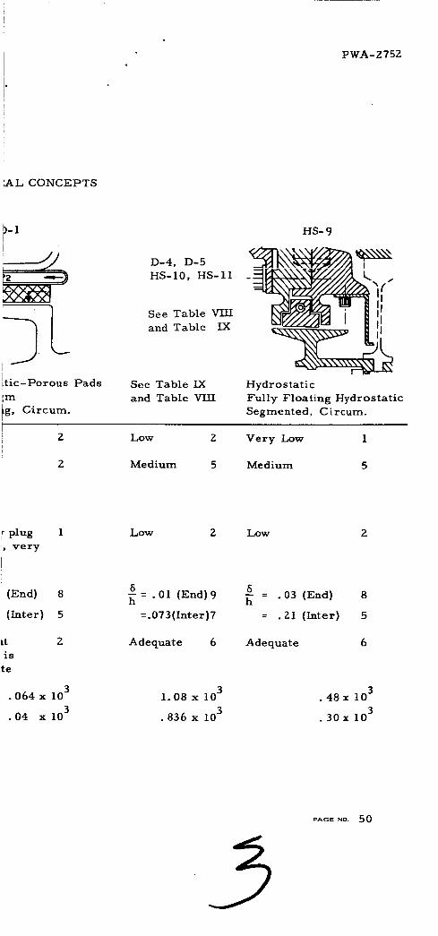
PWA-Z75Z
AL CONCEPTS
)-I!I
---JJ
i .ttlc-Porous Pads
_m
, Circum.
D-4, D-5
HS- 10, HS-11
See Table VIII
and Table IX
See Table IX
and Table VIII
HS-9
Hydrostatic
Fully Floating Hydrostatic
Segmented, Circum.
Low Z
Medium 5
Very Low 1
Medium 5
plug 1
, very
II
(End) 8
(Inter) 5
tt Z
is
te
• 064 x 103
•04 x 103
Low 2 Low 2
6= .01 (End) 9
=.073(Inter)7
Adequate 6
I. 08 x 103
• 836 x 103
5= . 03 (End) 8
= . Zl (Inter) 5
Adequate 6
• 48 x 103
• 30 x 103
SAGe NO. 50

PRATT & WHITNEY AIRCRAFT
RESULT1
Seal
Concepts
HSS- 1
HS-I
HD- 1
HD-3
D-I
D-4
D-5
Type of Seal & Seal Ring C!
Secondary SealI
Bellows or Piston
Face or Circum.
Bellows
Bellows
Dry Rub
Diaphragm
Solid Ring
Segmented, Face
Segmented, Face
Solid Ring, Circum.
Pis ton- Di aphr agm
Flexible-Ring, Face
Diaphragm- Hydros tatic
Flexible-Ring, Face
HS-9
HS-10
HS-11
Fully-Float. Hydrostatic
Segmented, Cir curn.
Piston
Piston
Flexible-Ring, Face
Segmented Ring, Face
*R t = RI Z R H
#Selected for Feasibility Analysis
/

TABLE XI
i
i
i
infigur ation
! Primary Seal
OF THE SCREENING STUDY OF END AND INTERSTAG£
First
Screening
Schematic Rating R I
Dr awing End Inte_
fdrostatic- step (Seg)See Table X
gdrostatic-FaceSee Table X
i
ydr ostatic- ShoeSee Table X
i. 78x105 . 5x10
I. 038x105 .692x
i. 38x105 .862x
ydr ostatic-ShoeSee Table X 0.805x10⁵ .504x
_dr ostatic- Porous Pads
:ydr ostatic
[ydr o static
See Table X
See Table VIII
See Table VIII
.81xl05
3.45xi05
.304x
2.30x[
I. 15 x 105 .767x
_ydr ostaticSee Table IX 6.45xi05 2.42x
lydrostaticSee Table IX 6.9xl05 4.6xl
lydr ostaticSee Table IX 3.2gxl05 2. 1 5x

SEAI_S
PWA- 2752
Seconde_ " "_"-_-' Screening Rt
Rating RII Rating x 10-13
End Inter End Inter
.192xi03 .12xl03
.072xi03 .056x103
.6O8 .O3
.0776 .0268
[05 .162xi03 .108x103 .308 • 08O
05 .324xi05 .216xi03 .21 .0548
05 .064xi03 .04xl03 .042i
05 1.08x10³ .836xi03 12.9i!
i
i05 1.08xl03 .836xi03 1.43
• 006
4.42#
.494
05 .48xi03 .30xl03 20.0 1.75#
D5 1.08xl03 .836x103 51.4
i
105 1.08x10³ .836x103 11.2
17.7#
3.86#
PAGE NO. 51

PRATT & _VHITNEY AIRCRAFT PWA-2752
Description of Seal Concepts
"r "r t_ ¢-', _ 1"1- 1 , , • _. _1
HSS-I, noo-c - nytarostatlc-otep - lnese two concepts represent
the basic hydrostatic step seal. The primary seal ring is segmented in
order to satisfactorily follow the irregular motion of the rotor. The
seal segments pressure balanced in the axial direction but not in the
radial direction. They are contained in a solid ring carrier which is
flexibly-mounted on a bellows or on a spring and piston type of support.
Leakage rate is quite favorable and is about 1/20 of that of the present
labyrinth design. Primary seal tracking is satisfactory for the end
seal _'"* may bc ..... *;*'_* .... _,_e interstage "_^_;~- _"......L,_ _*_,a_a,_,_ y for "1" u,=oJ._..,, u_._uS_ of
lower stiffness at the low pressure difference. The thermal distortion
of the seal segment is severe according to preliminary analysis but it
can be reduced to a safe level by shortening the segment; the elastic
distortion can be controlled in the same manner. The elastic distor-
tion can also be effectively controlled by increasing the moment of
inertia of the cross section. For off-design operations, the most
important consideration is the primary seal tracking. The pressure
difference during take-off is higher than that during cruising and there-
fore gives a more satisfactory tracking. During idle operation, pres-
sure is much reduced, but the speed is also lower and the end result
gives a response identical to take-off. During windmilling, the pres-
sure may reverse its direction; it may be necessary to retract the seal
ring away from the rotor for this condition. For sudden change of
operating condition or maneuver, the tracking of primary seal ring
might become difficult because of the sudden change of the thermal
environment. Detailed studies will be performed to insure satisfactory
performance during sudden maneuvering. The gas film should be
stable since there is no air pocket in the system. Dimensional stability
is marginal since any change of the step geometry due to wear will
cause significant changes in performance.
HS-1, HS-2, HS-4 (Orifice Compensated) - In these designs, the air
film is pressurized by the upstream high pressure air through orifices
distributed evenly along the circumference. When the film thickness
decreases, the flow becomes restricted and the pressure in the middle
of the air film increases, causing a positive stiffness of the gas film.
In the case of HS-1, there are two rows of orifices located at the inner
and outer radii of the seal ring to give a stronger angular stiffness.
The HS-2 design only has one row of orifices and a labyrinth back-up
sealat the inner radius of the seal. The HS-4 design also has a com-
pensating orifice and a recessed groove to provide a uniform pressure
at the inlet to the viscous film. A bellows is used as the secondary
seal for HS-1 and HS-4, but, for HS-2, the secondary seal is achieved
by floating the sealing ring hydrostatically in the carrier. All designs
use a solid ring.
PAOE NO. 52

PRATT & WHITNEY AIRCRAFT PW2_- 2 752
From the standpoint of leakage rate and primary seal tracking, the
orifice compensated seal appears to be quite attractive. However, the
thermal coning problem is very severe, since they are all solid rings.
The HS-I design has a flexible ring and also has more angular stiff-
ness to compensate for the thermal coning. The HS-2 and HS-4 designs
have heavier sections and therefore have more severe problems in
thermal coning. Off-design conditions appear to be satisfactory.
Stability of HS-I and HS-2 can be controlled by adjusting the orifice
diameter and the recess area around the orifice, but the central grooved
pocket for HS-4 contains a large high pressure reservoir and may be
sufject to pneumatic hammer. The geometry of these designs is such
that they are less susceptible to dimensional change due to wear than
are the step designs.
HS-3 - This design is an unbalanced seal in which the leakage is
prevented between two contacting surfaces. A quick calculation shows
that the heat generated using an extremely low unbalance factor (.05)
is too excessive to be considered safe. This design is, therefore,
ruled out in this screening study.
HS-5 and HS-6 - These two designs are basically the same as HS-4
except that the secondary seal is a spring and piston arrangement.
HS-6 uses a cascade of orifices to restrict the flow into the pocket.
Because the spring and piston design is more desirable than the bellows
used for HS-4, these two concepts have a higher total rating.
HS-7 and HS-8 - The basic arrangement of these two designs is
again similar to that of HS-5, with the exception that the high pressure
is from an external source which can be higher than the upstream
pressure. This gives considerable improvement in the static stiffness
for interstage seals. Slight improvement in the tolerance to high speed
can also be expected due to the high supply pressure at the orifice.
HD-1, HD-Z, HD-3, and HD-4- These designs share the common
feature that the pressure loading on the back face of the seal segments
is balanced by the film pressure generated hydrodynamically. In
HD-I, HD-2, and HD-3 the hydrodynamic pressure is produced by the
tilting action of the segments, whereas in HD-4, the pressure results
from a series of steps or tapered pads. All four designs indicate a
segmented approach.
A preliminary calculation shows that the hydrodynamic action will
not become active until the film thickness drops below 0.0005 inch.
At this low film thickness, the leakage is low, the static stiffness is
PAGE NO. 53

PRATT & _/VHITNEY AIRCRAFT PWA-2752
high, and the heat generation becomes considerably higher than for
other designs. However, by proper control of the segment length,
thermal distortion could be kept under control. The weakest point of
each of these four designs lies in the high secondary seal friction
caused by excessive unbalance of the side pressure exerted ovei _ the
secondary sealing surface.
From the standpoint of reliability, the extra load capacity produced
by the hydrodynamic action at extremely thin film thicknesses should
give a higher tolerance to high speed rub during bottoming. Tracking
under off-design conditions appears to be satisfactory. Film stability
does not seem to be a serious problem since tilting pads have operated
at speeds much higher than the proposed speed for these seals and have
not experienced any instability problem.
SG-1 and SG-2 - In these two designs, the pumping action of the
spiral grooves is used to generate the extra pressure to obtain a posi-
tive stiffness of the film. The characteristics and performance of the
spiral groove design are very similar to other hydrodynamic seals.
For this reason, they have individual ratings almost identical to the
HD-series with the exception that the thermal distortion is much more
severe because of the solid ring design.
HS-L-1, HS-L-2, HS-L-3 and HS-L-4 - Sealing in these designs
is achieved by floating a flat face plate against several close-clearance
labyrinths. The leakage rate of these concepts is expected to be much
lower than the present labyrinth seals since the gaps are now con-
trolled and kept at a very small clearance. In HS-L-1 and HS-L-2, the
height of the knife edges increases slightly along the flow passage and
forms a tapered gap. As the gap decreases, the restrictor becomes
more effective at the exit side and raises the pressure level between
the knife edges to provide a positive static stiffness for this seal. In
HS-L-4, the height of the knife edges is uniform along the flow passage
and the static stiffness is achieved by feeding high pressure air into
the mid section of the seal. HS-L-3 is a hybrid design which uses the
hydrostatic pad to control the close clearance of the labyrinths.
The major shortcoming of these designs is the lack of dynamic
stiffness when subjected to high frequency excitation. The large air
pockets between the knife edges act like a very soft spring and give very
poor response at high frequencies. In spite of the fact that these de-
signs have low thermal distortion, high tolerance to dirt, and reason-
ably little danger during occasional rubbing, the overall ratings of
close clearance labyrinth seals are extremely low due to lack of track-
ing capability of the primary seals. The hybrid design (HS-L-3) has
improved tracking capability but still shows a low overall rating com-
pared to other designs.
PAGe NO. 54

PRATT & WHITNEY AIRCRAFT PWA-2752
V____L- Perhaps this design is the most unique one among all all the
suggested concepts. It retains all essential features of the present
labyrinth seal except that small jets are introduced between the labyrinth
teeth to deflect the flow path and to induce a vortex pattern. These
vortex motions can provide additional resistance to reduce the leakagerate.
A preliminary experiment was conducted using water flowing
through a plastic model with the same labyrinth geometry as suggested
in this design. No substantial reduction of leakage rate (< 10%) has
been found in this preliminary test. Consequently, this design has been
ruled out by an extremely small individual rating in the leakage rate
consideration.
F-l, F-2 and F-3 - The fundamental principle of these concepts
departs quite drastically from the other designs in that one of the seal-
ing members is made very flexible. In all three designs, the centri-
fugally-activated foils have been used as the flexible member. In the
design F-l, a thin annular foil is deflected to the shape of the station-
ary primary sealing surface. This design has no provision for axial
adjustment. In F-2, the foilis keptunder radial tension by the centri-
fugal load produced by a concentrated rim at the outer radius. The
primary seal ring is floated hydrostatically in the carrier. The F-3
design is an application of a circumferential foil seal. The flexibilityof the foil is oriented in the circumferential direction instead in the
radial direction. These foils are made of rectangular strips whose
thickness is determined by the centrifugal load required for sealing
the high pressure. They are bolted on the drum and the end of each
foil is overlapped by the next foil in the circumferential direction.
Leakage of these foil seals is quite favorable at a film thickness
of 0.001 inch. Primary seal tracking should not be a problem because
the foil has a low inertia. However, there exists one major short-
coming which is common to all foil designs, namely that the local
elastic deformation under an uneven highpressure distribution or
caused by variation from the design pressure difference can become
excessive and cause local contact at high speeds. In addition, the
thin foil may flutter at high tangential speeds. Because of these argu-
ments, seals using extremely flexible foils have not received a high
total rating.
D-I and D-2 - These two circumferential seal concepts utilize a
metallic diaphragm or pieces of diaphragms as the secondary seal.
In this manner, the seal segments are free to move radially in response
to the high frequency vibrations of the rotor and the thermal expansion
of the frame. The design D-I also suggests a porous material for the
PAGE NO. 55

PRATT = W.,TNEY A,RCRA_ PWA-Z 75Z
primary seals. The porous structure plays the same role as the ori-
fices described in the HS-type seals. The diaphragm has a shape of a
flattened tube which can be either a complete ring or sections of tubes.
In the design D-Z, two half "C" shape diaphragms are used as second-
ary seals which are welded onto the primary seal segments. The
diaphragms may contain intermittent slots to reduce the elastic stiff-
ness in the radial direction. Leakage through the slots can be reduced
by secondary thin foils on top of the slotted areas. Leakage of D-1 and
D-2 is estimated to be approximately equal to that of the HS-type seals
and is therefore highly favorable. Primary seal tracking is more than
adequate for the end seal version but is somewhat marginal for the in-
terstage seal version. Secondary seal side thrust is not balanced and
is a major problem with this concept. The overall rating for end stage
seals of this design is reasonably high compared to some of the other
concepts, but it is still far from acceptable for interstage seals.
D-3 and D-3A - This design consists of a series of L-shaped seg-
ments as the primary sealing member which employ the hydrostatic
and hydrodynamic seal concept described earlier. The side thrust
exerted on the primary seal segments by the pressure is balanced by
a tension strip anchored to the frame. The secondary seal for the D-3
design consists of a small, thin, hydrostatic-step ring backed up by a
U-shaped diaphragm which is secured to the frame. The D-3A design
is an alternate design which uses the hydrostatically-balanced piston as
the secondary seal.
Leakage rate for this design is about the same as for the other
designs. Primary seal tracking for end stage seals is considered only
marginal and is definitely unsatisfactory for the interstage seals be-
cause of the low available pressure difference. Considerations of
secondary seal friction and balancing, thermal distortion, off-design
performance, and gas-film stability are all acceptable. However, in
considering dimensional stability, these two designs received a very
low rating because of the difficulty in keeping the segments aligned with
the tension strips particularly, when they begin to creep at high tem-
peratures. This is the main reason why high ratings were not given
to the L-shaped design.
D-4, D-5 and D-6 - In these three designs, a flexible ring is used
as the primary seal. Both the bending and torsional rigidity of the ring
is kept small to allow it to follow any runout, initial waviness, or
thermal twisting of the rotor. On the other hand, it has enough rigidityin the radial direction to resist excessive local deformations. It is
mounted flexibly upon the seal carrier by means of a U-shaped diaphragm
which must be flexible enough to allow the seal section to move a small
_AGE NO. 56

PRATT & WHITNEYAIRCRAFT PWA-2752
axial distance or to rotate through a small angle. The seal ring and
carrier assembly is, in turn, flexibly-connected to the frame by a
tension spring which retracts the seal when the pressure drops below
a certain prescribed value. Secondary sealing of the seal carrier is
achieved in three different ways. The pressure-balanced piston is
used in D-4; a hydrostatically-floated shoe with diaphragm backing is
employed in D-5; and a conventional bellows with a realistic dimension
is used in D-6. The leakage and primary seal tracking ratings are
comparable to the hydrostatic-pocket configuration. Secondary seal
friction and balancing are considerably improved for the D-4 design,
but are still far from acceptable for designs D-5 and D-6 due to balanc-
ing difficulty of the bellows or the floated shoes° The severeness of
the elastic and thermal distortions of the primary seal ring is consid-
erably relieved because of the flexibility. This results in much im-
proved total ratings for these three designs compared to some of the
concepts suggested earlier.
HS-9 - This particular design is designated as the two-side floated
shoe, circumferential seal. The seal ring is segmented and contains
hydrostatic bearings between the side walls and the housing. The ob-
jective of these bearings is to allow the segment to adjust freely for
rotor vibration, runout and initial waviness. The leakage through the
bearing clearance can be made acceptable by keeping the clearances
below 0. 0005 inch.
Initial studies indicate that the vertical and horizontal force balance
as well as the moment balance can be obtained by a slight adjustment
of a few key dimensions. The principal of operation for this second
seal concept has been described in detail earlier.
Leakage and primary seal tracking ratings were again based on
the hydrostatic pocket primary seal. The tracking rating is slightly
lower because of the higher irregular motion associated with the cir-
cumferential seal. The secondary seal friction and balancing were
rated very high because of the free floating action of the segments.
Other ratings are comparable to those given to D-4 concepts. The
total rating was found to be the highest for the endstage seal and the
second highest for the interstage seal.
HS-10 and HS-11 - The HS-10 design is another version of the
flexible ring face seal. The basic features are very similar to the
D-4 design except that the U-shaped diaphragm is now replaced with a
fully-floated piston ring. The thin strip is spring-mounted to the
secondary seal carrier and is allowed to follow any runout, wobble, or
initial warping of the rotor face. The seal carrier is in turn free to
PAGE NO 57

PRATT &, WHITNEY AIRCRAFT PWA-- 7. 752
move the full 0.4 inch of axial motion required for compensation of
thermal expansion. It is also sealed by _ _pcond piston ring. The
second order motions required of the two piston rings, arising
primarily from thermal changes, will be possible due to machine
vibration. A back-up labyrinth is also used when the seal ring is in
its retracted position. This is a segmented face seal with the segments
supported hydrostatically on one side only instead of on two sides as in
the HS-9 design. The bearing surface between the seal carrier and
the segments is extended below the level of the primary seal surface
"-_._,_-_e_-to _._-._-1.... _ the s_A___pr_=_u_.... . The segments are free to follow
the irregular motion of the rotor. The carrier construction is similar
to that of the one-piece flexible ring design.
Since the basic construction of these two designs is similar to the
D-4 design, the individual ratings are almost the same in all criteria
except for secondary seal friction, balancing, and either thermal or
elastic distortions. The piston ring construction in I-IS-10 appears to
be superior to the U-shaped diaphragm due to the uncertain behavior
of the thin diaphragm under high pressures. According to the total
rating of HS-10, it appears to be the most favorable choice for both the
end and interstage seals. The HS-11 design received a lower rating
compared to HS-10 mainly because of the additional leakage through
the segments and the possible rocking of the segments due to dynamic-
ally unbalanced moments.
PAGE NO. 58

PRATT & WHITNEY AIRCRAFT P "W"A -- Z 75 Z
MTI FEASIBILITY ANALYSIS
The feasibility analysis of compressor end seal and stator inter-
stage seal concepts conducted to date by MTI is presented in this sec-
tion of the report. The material presented in this section was prepared
by ]Dr. H. S. Cheng, John Bjerklie, and Dr. D. F. Wilcock. They
wish to acknowledge the major contributions made by Dr. V. Castelli,
Dr. T. Chiang, and Mr. C. Chow in preparing this material.
Summary of Feasibility Analysis
Typical engine conditions were used in the screening study analysis
of seal performance. Since the prototype seals will be tested in an
apparatus incapable of simulating engine pressure levels, practical
test pressure levels have been used in the feasibility analysis com-
putations without departing from either the letter or spirit of the speci-
fied engine conditions. The pressures, temperatures and other condi-
tions are summarized as follows:
End Seal Interstage Seal
Cruise Take-Off Cruise Take-Off
Sliding Speed, ft/sec 850 785
Air Temperature, °F 1200 680
Pressure Differential, psi 80 150
*".=AirPressure, Low Pr. Z0 20
Side, psi
850 785
IZ00 680
25 50
20 Z0
;_Air Pressure, High Pr.
Side, psi
CPressure Ratio
I00 170 45 70
5 8.5 2.5 3.5
':-'Determined by test rig capability; does not simulate engine pressure
levels.
Primary Seal Analysis
Dimensionless variable charts are being prepared for five basic
seal geometries. Included in this section of the report are (a) load,
center of pressure, stiffness, and mass flow as a function of film
thickness, step width ratio and pressure ratio for the hydrostatic step
seal; (b) mass flow rate for the spiral groove hydrodynamic seal; (c)
the computer program which will be used for the Rayleigh step seal;
(d) load, stiffness, and flow for .the hydrostatic orifice seal; and (e)
load versus film thickness for the hydrostatic labyrinth seal.
PAGE NO. 59

PRATT & WHITNEY AIRCRAF--T PW,,A- 2 7 5Z
•1_le thin strip designs listed on _=e _ require thatThe _1 _.-
there be a restoring moment generated in the primary seal whenever
the strip is not parallel to the runner at any position around the cir-
cumference. This restoring moment must overcome elastic moments
due to local twisting and error moments resuiting from manufacturing
tolerances and varying seal positions in the secondary carrier. The
resulting angular displacement must be small enough to maintain a safe
film thickness. A criterion for evaluating this situation has been
developed. A number of muitiple pad designs are being examined for
their capability in terms of angular moment stiffness.
Seal Response
The dynamic equations permitting the determination of minimum
film thickness as a function of seal mass, primary seal stiffness, shaft
speed, and the frequency and magnitude of runner errors have been
developed and plotted in non-dimensional form.
The criteria for evaluating the possibility of encountering self-
sustained oscillations in a thin strip seal have been determined and
applied to a typical seal section.
Seal Designs
Seal designs were not undertaken during this time period pending
completion of sufficient primary seal data to permit efficient detailed
circulation and design.
Primary Seal Feasibility Analysis
Since the completion of the Screening evaluation, more extensive
and detailed information on primary seal performance has been re-
quired in order to permit adequate overall design calculations to be
made. While these primary seal performance calculations are not
completed at this stage, the following subsections summarize the in-
formation generated to date on the Hydrostatic Step Seal, the Spiral
Groove Hydrodynamic Seal and the Rayleigh Step Seal. These are
adequate for the floated shoe design work.
For the designs employing the flexible thin strip concept, additional
primary seal work is required. The flexible strip requires a substan-
tial transverse moment capability from the primary seal in order to
balance elastic moments from small angular twist and error moments
arising from manufacturing tolerances and off-design pressure con-
ditions. Creation of this transverse moment capability in the primary
seal has necessitated study of several multiple pad designs together
with careful analysis of the moments to be balanced. At this writing
it is not certain that a successful design can be produced.
PA6E NO 60

PRATT & WHITNEY AIRCRAFT P WA - _- 752
The Hydrostatic Step Seal
In the screening report, preliminary consideration was given to
the load capability, the stiffness and the flow through a hydrostatic
step seal. For the detailed design analysis, the center of pressure,
or the position of the net load vector, is also required to determine
moment equilibrium.
This subsection contains the design charts needed when using the
hydrostatic step seal. These are expressed in terms of dimensionless
quantities (combinations of dimensional variables) so that their ap-
plicability can be as broad as possible.
The principal dimensions and pressures of the hydrostatic step
seal are defined as follows:
bl, b2, b
h I, h Z
Pl' Pi' PZ
m
R
W
width, inches
height, inches
pressure, psia
mass flow/unit circumference,
in Z Zgas constant, /sec - R °
load/unit circumference, ib/inch
ib- s ec
in Z
XC
distance from high pressure edge to center
of pressure, inches
The dimensionless quantities used in the design charts are:
m
b I = step width ratio = bl/b
H = height ratio = hl/{h2-hl)
rip - = pressure ratio = PI/P2
m
W
KS
M
X
C
dimensionless load = W/(P2-P1)b
dimensionless stiffness = KS
(P
h I
Z - Pl ) Hb
dimensionless flow
mffhl3 {PZZ 1\24 " b) \RT2 /
dimensionless center of pressure -
X
C
b
PAGE No. 6 1

PRATT = WHITNEY A_RCRAFT PWA- Z75Z
b
Load - The dimensionless load W is shown in Figure Z3 as a function
of the height ratio H for a step width ratio bl of 0.75. Curves for pres-
sure ratios of 0.1, 0. Z, 0.4 and 0.57Z permit interpolation for all
pressure ratios of interest. Figures Z4 through Z7 show similar curves
for step width ratios of 0.5, 0.35, 0.25 and 0.1Z5, respectively.
i I
I b I =0.75
0310.2 I
H=hl/(h2-h I)
1I
Figure Z3 Load Curve-Hydrostatic Step, bl = .75
_ASE _o. 6Z

PRATT & WHITNEY AIRCRAFT PWA- 2752
H=hll (h2-hl)
Figure 24 Load Curve-Hydrostatic Step, 61 = .5
I0 -z I0- I I I(3
H= hi I (h?..-hl _
Figure P5 Load Curve-Hydrostatic Step, 61= .35
PAGENO. 63

PRATT & WHIYNEY AIRCRAFT PWA-2 75Z
I l! t l t_l_l
*Jlt
0.8I
J"- 0.7
I_ 0.6
05
0.4
0.3 I
10-2
III 'iI1'I
i
-'m
Lli
llll
i0-1
If!! !l! .o2_ !I!1
, _,_
t
1
! ii
!
I!
,I
I
!lJ
!!!Jtl111
10
= ?-5Figure Z6 Load Curve-Hydrostatic Step, 7Ol "
I0
Figure 27 Load Curve-Hydrostatic Step, [o 1 = • 1Z5
PAe_ NO. 64

Center of Pressure - The dimensionless center of pressure x is
shown in Figures 28 through 32 as a function of H for the same values
of b, and r12.
0.45
0.4
0.35
Figure 28
I0 -2 I0 -I I I0
H- hll(h2- hI)
Center of Pressure-Hydrostatic Step, bl = " 125
0.45
°Ii
ix °
0.40
0.35
I0- 2 I0- I I I0
H" hl/(h2-h I)
Figure 29 Center of Pressure-Hydrostatic Step, bl= .25
PAGE NO. 65

PRA'n-= WHITNEYA,RC,:,A_r PWA-Z75Z
tlII I,, ,iI,, ! t o_1il _ i!11i_ +_+__=± ! I !_111 , ' i ,, ' ii =
Figure 30 Center of Pressure-Hydrostatic Step, bl 35
i0-2 i0-I
--_'= hI/( h2-h I)
_-I LJ-
I},= 0.5 L--L
-II
---i----+-
I0
Figure 31 Center of Pressure-Hydrostatic Step, bl = .5
,=,A_,,,o.66
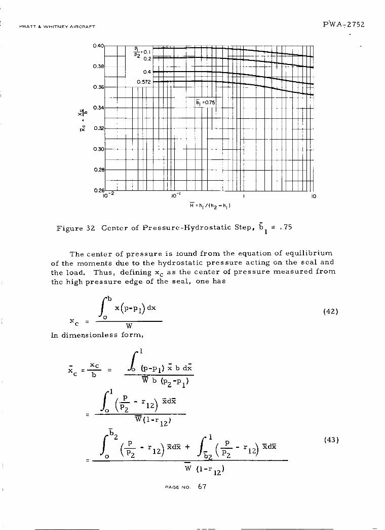
PRATT & WHITNEY AIRCRAFT P_i_i/_-A -- 2752
0.38
0.3E
0.28
0.26I0 -2 IO-I I IO
H =hl/(h2-h I)
Figure 32. Center of Pressure-Hydrostatic Step, bl = .75
The center of pressure is iound from the equation of equilibrium
of the moments due to the hydrostatic pressure acting on the seal and
the load. Thus, defining x c as the center of pressure measured from
the high pressure edge of the seal, one has
foX C -- W
In dimensionless form,
(42)
- x CX =u __
c
1
(P-Pl) _ b dl
b
W b (pz-pl)
W(l-rI2)
_d_ +z( p
w (1-r lz)
(43)
PAOENo. 67

PRATT & WHITNEE-'Y" AIRCRAFT PW A- 2752
From equation (15), one has
OSo C
2
2b2 2 3 r12b2
= ---- 2 'ri2 215 (l_ri2) 2 -5)ri2+ 2
(43a)
From equation (16), one has
2
2bZ )2[($r 1 r12 2ri2]15 (r12 - ri2
rl2bl 2b2_1 i2 + ri2 r12 + r12
(Z-bl)+ _ - ri z + rl z
Substituting equations (43a) and (43b) in equation (43), one obtains
- ri2 )
+(,_j[(r12 i
- _ I
3]tr 2 - 5)ri2 + 2 2T)1 2 2
(1- r2_2i2/ + _ (l-bl) rip'+rl2ri2rl2÷rl2÷ ri2
(44)
(43b)
RAGeNO. 68

PRATT & WHITNEY AIRCRAFT PW.¢_ - ?_ 75 ;).
For the cases where I- riz _ 0, the second term in the bracket of
equation (44) is undefined. However, the pressure distribution within
the region of 0-<x -<b 2 can be made linear from equation (15) as
Performing the integration as shown in equation (43a), one obtains the
following form.
)2[](1-]_1 3r126 I+2 ri2-
x is plotted against H at different b 1c
and r12.
The computer program used to generate the data for Figures 28
through 32 is presented in Appendix C.
Stiffness - The dimensionless stiffness K is shown in Figures 33s
through 37 as a function of H for the same values of b, and r12.
Figure 33
,=-oii
I0-Im
i0-2
-3I0
10-2
HYDROSTATIC STEP
10 -I I 10
=hi/ (h2-hi_
Dimensionless Film Stiffness-Hydrostatic Step, bl = " 125
PAGE NO 69

PRATT & WHITNEY AIRCRAFT PWA-2752
I I I ill - 3 E'____ i z,, _ tlI1111_=1_t- I I I llIIlJ'---_ ] I I-I I' ,,,,,b,=o.2_e-+-H-_I 11II . ] _ i I Illl
_ I ]1=ti F-I- i
10-11 I I tPt _.:r , ,,, ; I
P2 ° _F I I ltltl _! I i IIII]
I'l I_ I ! I tlIltll //_" , [llI=, _l,t It1111,
"1 " I I t JJ_ll_J///I I I I illlt i_1
I0- I_F-- , _I_H_HYDROSTATIC STEP_
,o;[, IlJll !1ii[I0-1 I I0
R:.v(._-.,)
Figure 34 Dimensionless Film Stiffness-Hydrostatic Step, 61= .25
IO-I
IY
|0-2
10-3
10-2
0J
02"
).5:2
I0 -I !0
Figure 35 Dimensionless Film Stiffness-Hydrostatic Step, bl = .35
PAGENO. 70

PRATT & WHITNEY AIRCRAFT lZ) "_-'_ -- 2 75Z
Figure 36
Figure 37
i0-I
I_= l'r
i!
i0-2
10-310-2
I ....
E_
r
T
i
÷
i -_-P-2Pl=0.572 2,_'/_)i _ ""
i1111 _,,
#I-I I t _ _,,_-" 'l HYDROSTATIC STEP-
I i/A rfIXm
17,_/
,_'(.2 I
10-1
H=
i llll
I
hI /( h2-hl_
--7--7;1:0._ i !
I
i
=
Ii
i
i
i
i
I
i
i
i ,
I0
Dimensionless Film Stiffness-Hydrostatic Step, L)].
':lJ=_ii
i_=
io-i
10-2057_ _ 0
Ji,
_,- ,,;_- 11
/f/O7 II= ill
KS __-_,11_
i ii
th 2 t
-"lI'i
I
!t
t
t
Pl
Ii
|
10.3 __
10-4
I0 -2 I0 -I I I0
R=hl/(h2-h l)
Dimensionless Film Stiffness-Hydrostatic Step,I
= .5
=. 75
P/_(3E NO. 71

PRATT _ WHITNEY AIRCRAFT t::)W_I_ -- 2752
Referring to Equation (Z0) of the Screening Study,
less stiffness of a step-seal can be written as
dW KshlK
s dH
the dimension-
(46)
Thus, by the chain rules of differentiation, Ks can be readily
obtained from Equation (18).
(47a)
From Eq. (18), one obtains
i
dW d
dri2 dri2- rlZ 1
d
dri2
(47b)
i
PAGE NO. 72
III t, i

PRATT & WH ITN EY AIRCRAFT ]J} W.A - Z 7 5 2
Where
b 1
bl b
b Z
_2 = b
and
@ b 1
b 1 -b Z
Equation (14) can be written below
(47c)
ri2 3 ri2 , 7g3 + bl (1 + _)3 J
1/Z
(47d)
From which,
dri2
dH
, N)3] z[_3+b I (I+
'-% _J(41
PAGe NO. 73

PRATT & WHIT_IEY AIRCRAFT PWA-2752
Substituting Eqs. (47b) in (48) and the resultant into Eq. (47a), one obtains
KS
(49)
g
Mass Flow - The dimensionless mass flow M is shown in Figures
38 through 4?- as a function o£ H for the same values of bl and r12.
1.0
0.8
I_1=0.6
0.4
0.2
0I0- 2 I0-I I I0
.,.(.¢.,')
Figure 38 Dimensionless Mass Flow-Hydrostatic Step, b = . 1251
PAGE NO. 74

PWA-2752PRATT & WHITNEY AIRCRAFT
bl = 0.25
1.0
010-2 I0 -I I
Figure 39
3.5
3.0
2.5
2.0
1.5
1.0
(.2-.,')Dimensionless Mass Flow-Hydrostatic Step, b = .Z5
1
b1=0.35 ]
0.2
0.4
0.572
I
I0
0.5
010-2
Figure 40
I0-I I
-_=",/("2-"b
Dimensionless Mass Flow-Hydrostatic Step, bl= .35
I0
PAGE NO. 75

PRATT & WHITNEY AIRCRAFT P WA -- _" 7 5 Z
|.4 ...... %=o51.2
1.0
0.80.6
0.4 =
°I10-1 I
;.,.(h2--h,)I0
Figure 41 Dimensionless Mass Flow-Hydrostatic Step, b = .51
1.0
0.8
0.4
0.2
010 .2- I0 -I I
bl "0.75
Figure 4Z Dimensionless Mass Flow-Hydrostatic Step, bl = .75
I0
PAGENO. 76

PRATT & WHITNEy AIRCRAFT 'PWA-2752
Spiral-Groove Hydrodynamic Seals
Description - A hydrodynamic spiral-grooved seal consists of
two members, one with a smooth surface and the other provided with
numerous spiral grooves as shown in Figure 43. Either one of these
surfaces can be moving. In the presence of viscous shear and appro-
priate geometry of grooves, a viscous pumping action exists between
the two edges. The pumping action creates a higher resistance to
flow between the high and low pressure edges.
As mentioned previously in the Screening Report, the effect of
viscous pumping action depends on the film thickness between the two
seal members. The groove geometry also influences the effect of
pumping. The groove parameters are the angle, the width ratio, the
length ratio, the depth ratio, and the number of grooves. However, in
this report, only the fully-grooved seal of narrow width with a suffi-
ciently large number of spiral grooves is considered.
b
Y
COLLAR ___
HOUSING
Figure 43 Hydrodynamic, Spiral-Grooved Seal
PAGE NO. 77

PRATT & WHITNEY AIRCRAFT PWA-2752
Governing Equations - A mathematical derivation of the pressure
distribution in a hydrodynamic, grooved seal with an isothermal gasJ_il ........ 1. .... J: ....... -'_ __1 f_-,_m Lnay be t .... ._ - ,,___ IIUII-- Ul II1_ I1 b l Ulld I £UJK IIl_ tll_
Equation of pressure can be written as
_K 2
d__ AK1dy
(50)
where
= P/Pl
= y/b
A
M
K 1
_ 6IXUb2
Plhl
lZIXb=m
Plhl 3P 1
(H 3 1) (H-l) sin 2[3
cos 2_
K 2
U
tx
m
P 1
mean speed, in/sec
viscosity of gas, lb-sec/in 2
mass flow,lb - sec
2in
Density of gas at Pl'
2Ib- sec
4in
cos 2_
PAGE NO. 78

PRATT & WHITNEY AIRCRAFT IDWA - 2752
H = groove height ratio = hz/h I
A = groove width ratio = A /Ag r
= groove angle
For a fully grooved seal, Equation (50) becomes
$1yP2 MK2 i o
_d_ = AK d_
1 _-AN
I
(51)
therefore,
= (\%2-- " 1/% + MAK 1
(5Z)
where
P2 = PZ/Pl
and
M = M K2/AK 1 .
m
Discussion - The sense of mass flow (M) is negative when the direc-
tion of flow points toward the low pressure side. By observation of
Equation (52), it is seen that, for a constant compressibility number
and groove geometry:
(a) M = 0 (Condition of no flow and a perfect seal) when
P2 = P2 = 1 + AK 1
PAGE NO. 79
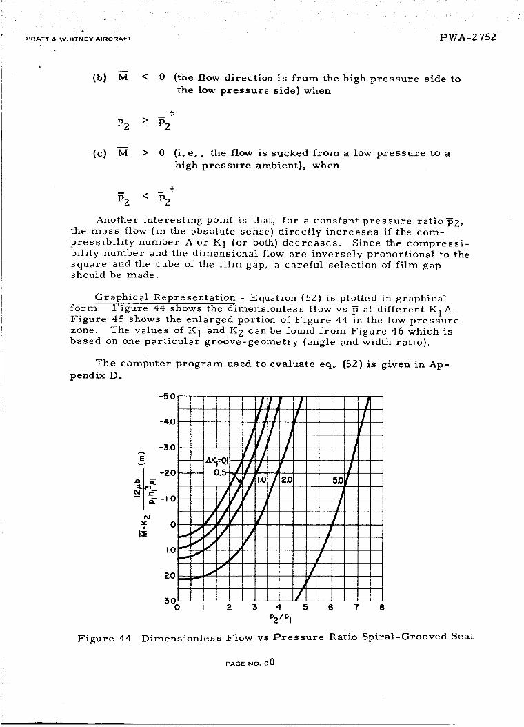
r PRATT & ttVHITNEY AIRCRAFT PWA-2752
m
(b) M < 0 (the flow direction is from the high pressure side to
the low pressure side) when
m
(c) M > 0 (i.e., the flow is sucked from a low pressure to a
high pressure ambient), when
Pz < Pz
Another interesting point is that, for a constant pressure ratiop2,the mass flow (in the absolute sense) directly increases if the com-
pressibility number A or K 1 (or both) decreases. Since the compressi-
bility number and the dimensional flow are inversely proportional to the
square and the cube of the film gap, a careful selection of film gapshould be made.
Graphical Representation - Equation (52) is plotted in graphical
form. Figure 44 shows the dimensionless flow vs _ at different K1A.Figure 45 shows the enlarged portion of Figure 44 in the low pressure
zone. The values of K 1 and K 2 can be found from Figure 46 which isbased on one particular groove-geometry (angle and width ratio).
The computer program used to evaluate eq. (52) is given in Ap-
pendix D.
Figure 44
-5o lJ r I1[ I-4.0 ! 1 / /
,Ill
l! I /_ -3.o tJl I--_eoi j I / f
///-_1:: G'J J /
" 4/j/ , /Y
I:_ 0_./// / j
,.o_'/ / "/ /
• /f
1
I i / i0 I 2 5 4 5 6
P2/Pl
I
/
I7 8
Dimensionless Flow vs Pressure Ratio Spiral-Grooved Seal
PAOe NO. 80

PRATT & WHITNEY AIRCRAFT ]PW-_- 275;Z
-I.0
-0.5
_- o
,,,-oo,__'o, ,"/_,__ _o.5
I:_ 0.5 ==- _ _ _"_-
/
I.O0 0.5 1.0 I. 5
P21P I
Figure 45 Dimensionless Flow vs Pressure Ratio Spiral-Grooved Seal
2
_F
1.0
.6
\
.4
.2
o/
/f_
A=Ag/Ar : 1.9 ,.B=72 °
/ \,<xK,
K2
II _ _"_" ""'-'_
2 5 4 5 6 7 8 9
H = hz/hl
1.0
Figure 46 Coefficients 141 and Kzfor Spiral-Grooved Seal
PAGE NO. 8 1

PRATT& WHITNEY AIRCRAFT PWA- 2 752
Charts on load, stiffness and center of pressure are not yet avail-
able. Because the spiral groove seal is basically a pump, it must be
combined with a restrictor before substantial toad capacity or stiffnessis attained. The restrictor may be a land {at the high pressure side) oran orifice feed.
R ayleigh Step
The Rayleigh Step (in a circumferential direction) is attractive as
a means of providing additional hydrodynamic support for the primary
seal. This is particularly desirable during moments of high load and
reduced film thickness, such as might be experienced during transients
or sudden displacements. T_.e D_..I_ _ _+_..... _, Step may _ used as_--.e _ a
shallow pattern on the lip of a hydrostatic step seal or as the primaryseal itself with a larger step.
The necessary information and charts to permit evaluation of the
Rayleigh Step in comparison with other approaches are not yet com-
plete. A new computer program was necessary to accomodate the
differing boundary pressures in this application of the Rayleigh Step
Pattern. The background of this program and the FORTRAN IV
statement are included as Appendix B.
Hydrostatic Orifice Compensated Seal
The expressions for the load and stiffness of hydrostatic orifice
compensated design have been derived earlier in the Screening Study.The pressure distributions in the upstream and downstream section are
exactly the same as the step seal given as Equations (15) and (16).
Following the procedure described earlier in the Screening Study,
the intermediate pressure can be determined graphically and the
dimensionless load can be readily calculated from Equation (29).
Results of W are plotted against a dimensionless film thickness de-
fined by
H = h _b CDT_ a /
These curves are shown in Figures 47, 48, and 49 for width ratios
of 1/8, 1/4 and 1/2, and pressure ratio of 0.1 and 0.2. The leakage
through the seal can be calculated from the flow equation for the down-
stream section, Equation (21). In Figure 50, the dimensionless leakageis plotted against the dimensionless film thickness. The dimensionless
leakage is defined by
M = m
24 _tb R'T2 t2h3_ P 2
(54)
F'AeENO. 82

PRATT & WHITNEY AIRCRAFT 1DW_- 275Z
The dimensionless stiffnesses, as defined by
dWK - l
s dH
( )1- dh (Pz-P1) _ pz-p1
h,-- K
(55)
are plotted against H in Figure 51 through 53.
To illustrate the use of these dimensionless charts, an illustration
example is presented.
Illustration Example
The problem is to design a hydrostatic-orifice seal to operate
under the following given conditions with maximum stiffness.
P1/P2 : O. 2
P2 = 100 psia
b = 0. 75 inches
bl/b = 0. 25
h = 0. 001 inches
T 2 = 1200 F
R = 2.47 x 10⁵ in2sec2 OR
= i. 0 inch
u = 5.9 x 10⁻⁹ lb. sec.in2
I ° Referring to the stiffness curve for b I/b
maximum stiffness at Pl/Pz = 0.2,
H = 0.56
and = K
= 0.48 s ss
O.56
= 0. Z5,
I
H
-: (p2-pl)
0.48 x--0. 001
x 8O
Figure 52, for
/in.
PAGE NO. 8 3

PRATT&WHITNEY AIRCRAFT PWA-2 752
. Referring to the load curves for b I/b
= 0.56
W = 0.81
= 0.25, Figure 48, for
. To determine the orifice radius, one must first find C D from
Figure 54 and also calculate P2"
From Figure 52, one locates C D = 0.83
P2 i00
P2 --
RT2 2.47 x 105 x (1200 + 460)
-72.43 x i0
2Ib sec
4in
IZ_ 2 I I/3
h _b C D wa-_- =
H P2 V RT2
and
24 _b C D _
/2
liE_.0x..g_.43x 47 x x 1660
10 -7 105
4x 5.9 x 10 -9 x0.75 x0.83 x 3.1416
-2= I. 13 x l0
oo,)x 56 I/2
PAGE NO 84
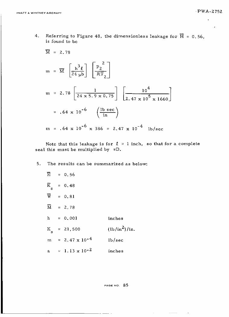
PRATT & WHITNEY A'RCRAFT "PW.A -2 75 ;).
4. Referring to Figure 48, the dimensionless leakage for H = 0.56,
is found to be
E
M = Z.78
m = M LRT2J
m = Z.78Z4x5.9 x0.75 ][,04]2.47 x 105 x 1660
lb sec)= .64 x 10 -6 \ in
m = .64 x 10 -6 x 386 = 2.47 x 10 -4 Ib/sec
Note that this leakage is for _ = 1 inch, so that for a complete
seal this must be multiplied by wD.
5. The results can be summarized as below:
H = 0.56
K = 0.48S
W = 0.81
M = 2.78
h = 0.001 inches
K = Z1,500 (lb/in2)/in.s
m = 2.47 x 10 -4 lb/sec
a = 1.13 x 10 -z inches
PAGE NO. 85

PRATT & V_HITNEY AIRCRAFT P W_L_ -- _ 7 5
0.95
o,i.l os
0.7
0.6O. I 0.2 0.5 1.0 2.0 5.0 I0
Figure 47 Hydrostatic Orifice-Load
-r TTTTT]
_L-L
-+-+-+-p-+-+
4-+-+-+-+-_
I n IEII
5.0 I0
Figure 48 Hydrostatic Orifice-Load
PAGENo. 86

'PWA-2752PRATT & WHITNEY AIRCRAFT
0.95
0.9
IPl-- :0,
IF2i
I
I
0.8 i --_._
i O.
l;
0.7
0.60.1 0.2 i 0.5
H=h
I-=c.5
IIi
i
i
i
i
1.0 2.0
xp2,V'k-'T2 7l/3
24 p,b C D_'° 2_1
5.0
I1[IIIII
!!L!
iI1[I
IIII!!!!iiIIIIIIII!!!!
IIII
IIIIIII1IIII
I
I
II
I
I
i1.0
Figure 49 Hydrostatic Orifice-Load
8
7
I
6
0.I
_ PL_o.I
, "_x
%1_ .C i L
I _-=0.125
% I :
Pl :0 _ /-b=0'25
1.0
II
-H'=hL24 p.bCDlro2J
Figure 50 Hydrostatic Orifice-Flow
itlll
,,,,,II.....II
.....ii!!!!!
.....liIiliiII!!!!!iiI I : ::
,!!!!II!!!!!I
IIII!!!
i: : : ::
____ _J_LLIJ_ I I
I0
PAGE NO. 87

PRATT & V_'HITNFY AIRCRAFT PWA-Z75Z
Figure 51
llZ
me
!v
"°I _._'ii,,,,"_=0.125
0.1II
lm0.0t
0.0010.01
--,__;o_"i i,_J,' i i
j//
0.1
- L,,,,_,,.°,j
IIII__IIII
ill
IIII
!L;_:;;;_i i ¸ii
,! !!...... I : : :IIII I I II]I I I Ill J I I Jill
I t tit11 _ !!![!I t I 11] I : ::::I t till I J .....! I L[?!l t ?ltll
I Illll I I !!!!!J i i i i i
I.O I0
I/3
Hydro static Orific e-Stiffne s s
?,
1.0
o.Ii
0.01
i
--m _bl _0.-- b
I
IJ
I
i1
1
I
!i
i t; I0.001
O.OI 0.1
//I
Figure 52 Hydrostatic Orifice-Stiffness
PAGE NO. 88

PRATT & WHITNEY AIRCRAFT PWA-2752
1.0
Irr(/)
ii0_
I_._
0.1
0.01
Pl
0"O010.01 O.I
_=hF..bCD.o2]
1.0I/3
10
Figure 53 Hydrostatic Orifice-Stiffness
/I
o,5
10 O8 O.6 04 0 _ 0
PRESSURE RATt0 PI/P2
Figure 54 Discharge Coefficient for Orifices. Experimental Data to
Generate this Curve were Taken From Reference 3.
PAGENO. 89
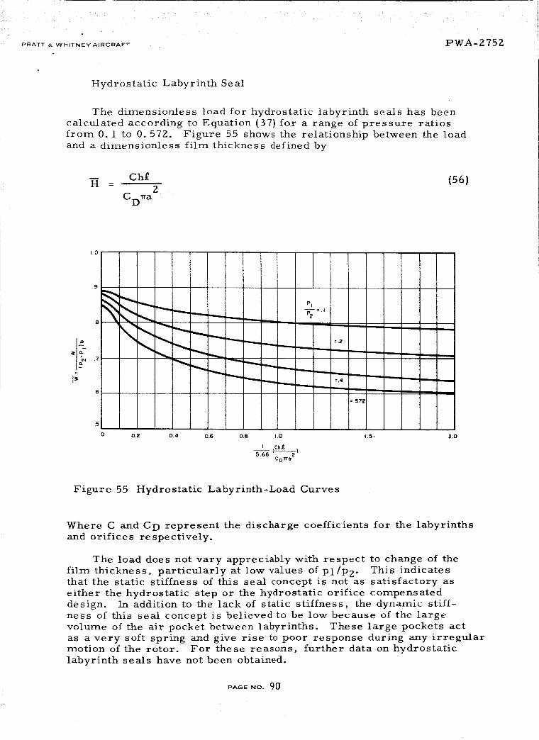
PRATT _ VCHITNEY AIRCRAFT PWA-Z75Z
Hydrostatic Labyrinth Seal
The dimensloniess load for hydrostatic labyrinth seals has been
calculated according to Equation (37) for a range of pressure ratios
from 0. 1 to 0. 572. Figure 55 shows the relationship between the load
and a dimensionless film thickness defined by
Cht (56)H -2
CD1ra
I;.6 ....
PI
7---=.2
o 0.2 0.4 o.s o.e i.o
I (cht.)5.66 C D l'r ° 2
m
=,4
",-mmm ,m.,.m
=.572
1.5, 2.0
Figure 55 Hydrostatic Labyrinth-Load Curves
Where C and C D represent the discharge coefficients for the labyrinths
and orifices respectively.
The load does not vary appreciably with respect to change of the
film thickness, particularly at low vaIues of Pl/P2- This indicatesthat the static stiffness of this seal concept is not as satisfactory as
either the hydrostatic step or the hydrostatic orifice compensateddesign. In addition to the iack of static stiffness, the dynamic stiff-
ness of this seal concept is believed to be low because of the large
voiume of the air pocket between labyrinths. These large pockets act
as a very soft spring and give rise to poor response during any irregularmotion of the rotor. For these reasons, further data on hydrostatic
Iabyrinth seals have not been obtained.
PAGE ,,,O.90

PRATT & WHITNEY AIRCRAFT "PWA-2752
Multiple Pad Designs with Thin Strip Seal
Among the seal concepts proposed for further feasibility studies,
two of the concepts rely upon the flexibility of a thin ring to follow
any runout and wobble motion and to compensate for any thermal coning
resulting from the frictional heating in the gas film. These are the
thin strip-one piece design and the thin strip-C diaphragm design.
In designing this seal ring section, two important factors must be
considered. First, the cross-section must have a sufficiently small
section modulus in order to allow it to follow any thermal coning with-
out resulting in excessive curvature along the radial profile. Second,
the restoring moment produced by the film pressure due to relative
coning between the seal ring and rotor must be sufficiently strong to cause
the seal ring to twist but not to touch the rotor either at the inner or at
the outer edge. On the basis of these two considerations, the directions
for design are certainly towards choosing a seal ring cross-section
having a minimum section modulus and a primary seal concept having a
maximum restoring moment. In the next section, a simple but important
design criterion is established for the purpose of determining the re-
quired section modulus and gas film restoring moment.
A Design Criterion for Thin Strip Seal - Consider a flexible seal
ring as shown in Figure 56.
OF ROTOR
MRES
L ROTOR
RING
Figure 56 Angular Displacement of Thin Strip Seal
PAGE NO. 91

PRATt• WH,TNEW A,RCRA_ PWA- 2752
The angular twist (a),the restoring moment by the gas film, as well
as other forces acting on the seal ring, are assumed to be axisymmetri-
cal in order to arrive at the first-order design criteria. The con-
sideration of any non-symmetrical deformations will be considered in
the fiexlble seal ring analysis.
Let _D denote the relative angular twist between the ring and the
rotor due to distortion from the axial thermal gradient or initial warp-
ing, and let MRE S designate the residual unbalanced moment which may
arise from imperfect manufacturing, off-design operation, or inexact-
ness in the prediction of the center of pressure. Of course, if every-
thing is designed and made perfectly and the thermal distortion is
small, then MRE S a'nd a D will be negligible. But, if they are not small,
L_le_ the _Lur11_g ri_oineliL from Lhe gas film must be large enough to
twist the seal ring into an angle within the allowable angle of twist, which
will be denoted by a A.
Let a e be the moment required to rotate the seal ring section throughone radian.
Referring to Reference 2,
EI
De = _(_--_ale - I_2c(5v)
where _ is the increment of the moment about the centroid of the cross-
section, Aa is the increment of the angular twist in the direction of the
acting moment. Ic is the area moment of inertia about an axis passing
through the centroid and perpendicular to the axis of the seal ring.
Let _f be the gas film angular stiffness which is defined by
(58)
where AMf is the increase of the gas film moment about the centroid in
the clockwise direction.
The net moment acting in the clockwise direction is
_f_ + MRE $ (59)
For condition of equilibrium, this moment must be equal to the moment
required to twist the ring from the angle aD back to a. This requires
(@ - @) (60)_f_ + MIRES = De D
PAOE NO. 92
PRATT & WHITNEY AIRCRAFT _)W 4- 2 752
Solving Equation (4) for a , one obtains
I' De MRES 1= _f + De aD - Pf + _e(6t)
If the absolute value of this angle is to be limited within a certain al-
lowable angle a A, one obtains the following criterion
_e MRES
#f+ De a D #f + #e < a A(62)
It is instructive to note that if _e -c°, which is the case of a rigid ring,then the criterion reduces to
a D < a N (63)
which simply means that the combined thermal and initial coning must
be less than the allowable angular displacement.
On the other hand, if De-43, which is the case of a perfectly flexi-
ble ring, then the criterion reduces to
MRES
(64)13f < _A or MRE S < aA_5 f
which means that the residue moment be less than the allowable coningtimes the angular stiffness.
It should be noted that this criterion is an important, necessary
one; it is by no means sufficient, since other problems associated with
non-symmetrical thermal distortion, static stability, and dynamic
response of the entire ring in the transverse and angular mode will
add further restrictions to the design requirements.
The criterion (62) indicates that thermal coning of the seal ring and
the rotor face must be kept at an absolute minimum. In the Screening
Study, it was shown that a coning of 0. 004 rad can be expected for the
seal ring. For the rotor face, it is particularly restrained but the
axial thermal gradient is expected to be higher; therefore, the coning
of the rotor face might be of the same order as the seal ring. As to
the residue moment, it can come from three sources: (i) inexact
prediction of both the centroid of a complicated seal ring section and
PAGE No. 93

PRATT _ WHIT'NEYA,_CRAFT PWA- 2 752
the center of pressure in the gas film, (2) manufacturing tolerance,
and (3) off-design operation and transient variation of pressure.
This seems to indicate that even if the seal ring is made perfectly
flexible, it would require considerable angular stiffness to overcomethe residue moment.
Since the primary seal for the thin strip concept requires a high
angular stiffness, none of the single-pad primary seal concepts con-
sidered in the Screening Report are adequate for this application. It
is necessary to seek other designs having a much wider base and hav-
ing more than one pad. The new designs considered for the flexible
seal are discussed in the following subsections.
Double Orifice Design - This design actually is a single pad but
with two rows of orifices intended to give stronger angular stiffness,
and two rows of spiral grooves for prevention of high speed rub at the
edges (see Figure 57). An analysis was made to solve the flow net-
work through the orifices and spiral grooves and a computer program
was written to calculate the load, stiffness and flow of this design.
The details of this analysis will be reported at a later date. In addi-
tion, the load and moment for a non-parallel film was analyzed by as-
suming the gas film is composed of three parallel films at differentlevels of the film thickness.
P2
A
P2 P2 P2 > Pl
o,L. '! I _1I_ b "7
A
t VIEW A-A
Figure 57 Double Orifice Primary Seal with Spiral Grooves
Using the following dimensions:
b = 3/4 inches
bl = b 2 = d = i/4 inch
al = =2 = 0. 005 inch
it was found that the angular stiffness, _f,
460 (in ib/in)/rad.
at h = O. 0009 inches is
PAGE NO. 94

PRATT & WHITNEY AIRCRAFT PWA-275Z
A cross section for this design and its dimension is shown in
Figure 58.
-_ _ .05"
52-I;3,,
--I=- I C iI'.125"
Figure 58 Cross-Section of a Double-Orifice Design
The area moment of inertia about its centroidal axis C-C is 5.55 x 10 -4
inches4. The elastic stiffness, _e, for a steel segment and a radius of13. 75 inches becomes
El 06 4 (in-lb]_ c 30 x 1 x5.55 x lO-
e K_2 - (13°75) 2 = 88 \ in / /rad
If one assumes that the value of a D can be controlled to within
0.005 tad. and the allowable_A is 0.001 rad., the criterion (6Z) gives
_ e ) MRES_f+Pe f e
< O. 001
To satisfy this criterion,
lowing limits
-.108 < MI_ES <
the residue moment must lie within the fol-
0. 988 in- lb/in
This limit is very narrow, and it indicates strongly that this design does
not have adequate angular stiffness.
Double Pad Design - When a vented groove is introduced in the
sealing area as shown in Figure 59, the single pad is split into two pads.
The right pad functions as a seal, and the left pad becomes a thrust
bearing used primarily to provide the needed angular stiffness. Of
course, with this design, the leakage is expected to be much higher
than the single pad design. A design compromise must be made be-
tween the angular stiffness and leakage.
_AGE No. 95

PRATT & WPII3:NEY All'CRAFT P "W'A-- Z 75
°,[..--,Pl p! P2
SPIRAL GROOVERAYLEIGH PAD
Figure 59 Double Pad Seals with Central Vent Groove
The axial stiffness of the left pad is much higher than the right pad
because a thrust pad is inherently stiffer than the seal. The angular
stiffness can be estimated by the following expression
JBf = klblt I + kzb g (__-_1 )Z (65)
Where kl and k z are the axial film stiffnesses in (lb/inZ)/in based on
the parallel film analysis, b 1 and b 2 are the widths of the pads; thedimensions, _, and _1 are shown in Figure 60.
PAGe NO. 96

PRATT & WHITNEY AIRCRAFT 1C)'_-Z_ .- Z ?5 Z
k2 b2
(LEFT PAD) A_,_ (RIGHT PAD)
,,f ---
Figure 60 Tilting of Double Pad Seal
If kl and k 2 are known, the ratio of the widths can be optimized and the
resulting expression is
b I
b I +b Z k 1
k Z
The ratio ofkl/kZ is about 2,
to be equal to 0. 414.
and using this value,
(66)
b 1
(bl + b2 ) is found
The magnitude of k I and k Z based on the previous single pad hydro-
static-orifice solution is approximately equal to 40,000 and 20,000
psi/in. Assuming these values for kl and k 2 and a total width of 1.25
inches, the calculated angular stiffness is 1,600 in Ib/in. rad.
The double pad design has one disadvantage, since a wider pad
would require a deeper section in the axial direction to achieve the
necessary moment balance. A deeper section would increase _e and_e
may not give a significant reduction in _ + _e " However, the double
pad design definitely increases the tolerance to residue moments since
both _f andDe will be increased with this design.
The primary seal concept considered for these pads is the hydro-
static spiral groove concept, or the hydrostatic-hydrodynamic Rayleigh
pads. The load axial stiffness, angular stiffness and the leakage of the
double pad design using the primary seal concepts are currently being
studied in detail; results will be reported later.
PAGE No. 97

PRATT & VVHITNE¥ AIRCRAFT PW,,_,--Z '75Z
Seal Response
Tracking - The dynamics of a seal segment within the framework
of the one-dimensional theory of vibration has been studied in detail in
the Screening Study. The response of the seal segment to any rotor
motion is characterized by the motion of the seal segment relative to
the rotor. Using Equation (lle) in the Screening Study, the seal re-
sponse can be expressed as
A -f6 n n 1
f f I- Z 2 Z _7 1/2
For the design concepts considered in this section, the only sources of
damping force appear to come from the internal damping of the seal
back-up spring and the gas film damping. Both of these are believed
to be extremely small in affecting the response. Assuming that the
damping effect is absent, the quantity 6/f n is calculated according to
n2 a_Zm - ks inEquation (11) and plotted against the parameter kfFigure 61.
Figure 61
- If if j
I
I
8
f.
//
//
• I Z .3 .4
n2r.u2m-k s
kf
Dynamic Response Ratio
//1
i¢ o
if
PAG_ NO. 98

Figure 62 shows the portion of the curve for small values of 8/f n on an
enlarged scale.
fn
/
/
/
nwc =0
kf
/
//
fn(n_c)2"11/2I_l - +
kf kf J
8 _ f.T =( )T-
I I
n2co2m.ks 2
Kf
Figure 62 Dynamic Response Ratio - Enlarged Scale
Flexible Seal Ring Vibration - The vibration of a flexible seal ring
supported by a gas film will be analyzed in this section. Figure 63shows a seal ring with a mean radius R and cross-sectioned dimensionsa and b.
RING
ROTOR
Figure 63 Thin Strip Seal Ring
PAGE NO. 99l
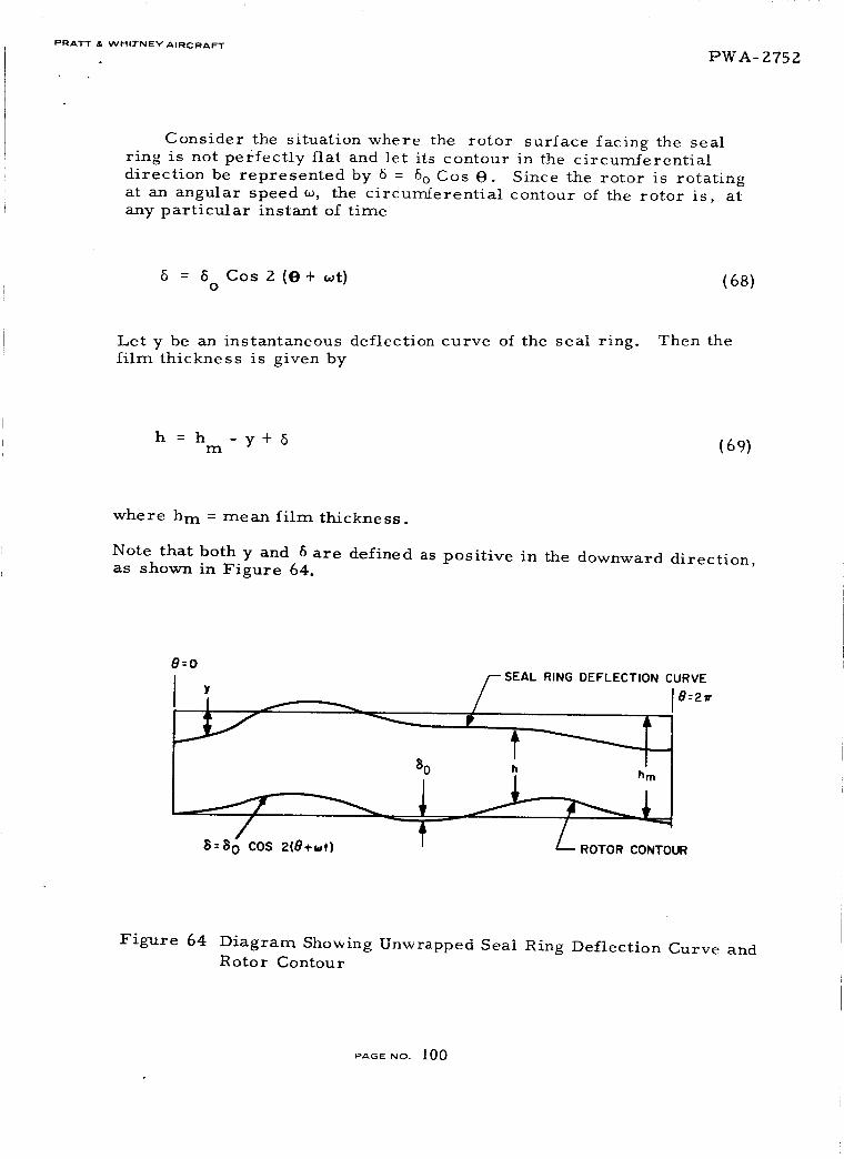
PRATT & WHI_FNEY AIRCRAFT PWA- 275 2
Consider the situation where the rotor surface facing the seal
ring is not perfectly flat and let its contour in the circumferential
direction be represented by 6 = 6o Cos O. Since the rotor is rotating
at an angular speed _, the circumferential contour of the rotor is, at
any particular instant o_ time
6 = 6 Cos Z (O + wt) (68)O
Let y be an instantaneous deflection curve of the seal ring. Then the
film thickness is given by
h = h - y + 6 (69)m
where h m : mean film thickness.
Note that both y and 6 are defined as positive in the downward direction,as shown in Figure 64.
8=0
y
SEAL RING DEFLECTION CURVE
!8:2T
8o
T_I8 =8 0 COS 2(0+_t) ONTOUR
Figure 64 Diagram Showing Unwrapped Seal Ring Deflection Curve andRotor Contour
PAOE NO. I00

PRATT & WHITNEY AIRCRAFT PWA-- Z75 Z
Taking a differential segment of the ring as shown in Figure 65,
the forces and moments acting on this element are shear forces V,
gas film restoring force q, bending moments M b, twisting moments M t,
and gas film restoring moment qa. Double arrow head denotes vector
representation (right hand system) of angular quantities. The equationsof motion can be written as follows.
Transverse motion (linear translation):
d.__V_VdO - qRd0 = (pARd0)_ (70)dO
M,. IZMb
lq
C_Mb_8
a8
Figure 65 Force and Moment Diagram of a Seal Ring Segment
Radial equilibrium of all moments
8@
a_ l
de - Mtd@ - VRde = Irr 88 R(Vl)
PAO:NO. i01

PRATT _ WHITNEY AIRCRAFT PWA-- Z75 Z
Tangential equilibrium of all moments
aM t
M bdo + a--_ dO-qaRd0 = Itt'a (72)
whe r e
Irr
T./a
tt
_ M{RZde Z +a z)
12
= M (a 2 + b 2)
1Z
Z
Z
M = mass of the segment = pabRdO
p = density of seal ring
A = cross-sectional area, ab
q = restoring force per unit length
qa = restoring moment per unit length
From (68) and (69) we have
q = k(y-5)
k(y-5 Cos 2 (O+_t)0
(73)
where k is the linear stiffness of the gas film per unit length.
PAGE NO. 102

PRATT & WHITNEY AIRCRAFT P'WA- 2752
To obtain q_, refer first to Figure 66. The restoring force distri-
bution due to an angular displacement eis linear across
I I I I I I I I I I
I-X
Figure 66 Force Distribution Across Tilted S_al
the width b. Integration of the moment of this distributed restoring
force about the center results in
b/Z Z dx 1 k_b zq_ Z kx _ b ig
0
(74)
Eliminating M t and V from Equations (70), {71) and (72), we obtain
1 82Mb 1 kb2e
R 2 88 Z R 2 Mb + 12 R q
1 pA a 2 a
pA# - 1--7 i_ , + bZ) _ +---R"- 80 J (75)
Before going any further, obtain a relationship between M b and the
displacements y and a. Again, take a segment of the seal ring with
length Rd@. Due to angular (twisting) displacement e, the upper portion
is compressed while the lower portion is stretched (See Figure 67).
PAGE No. 103
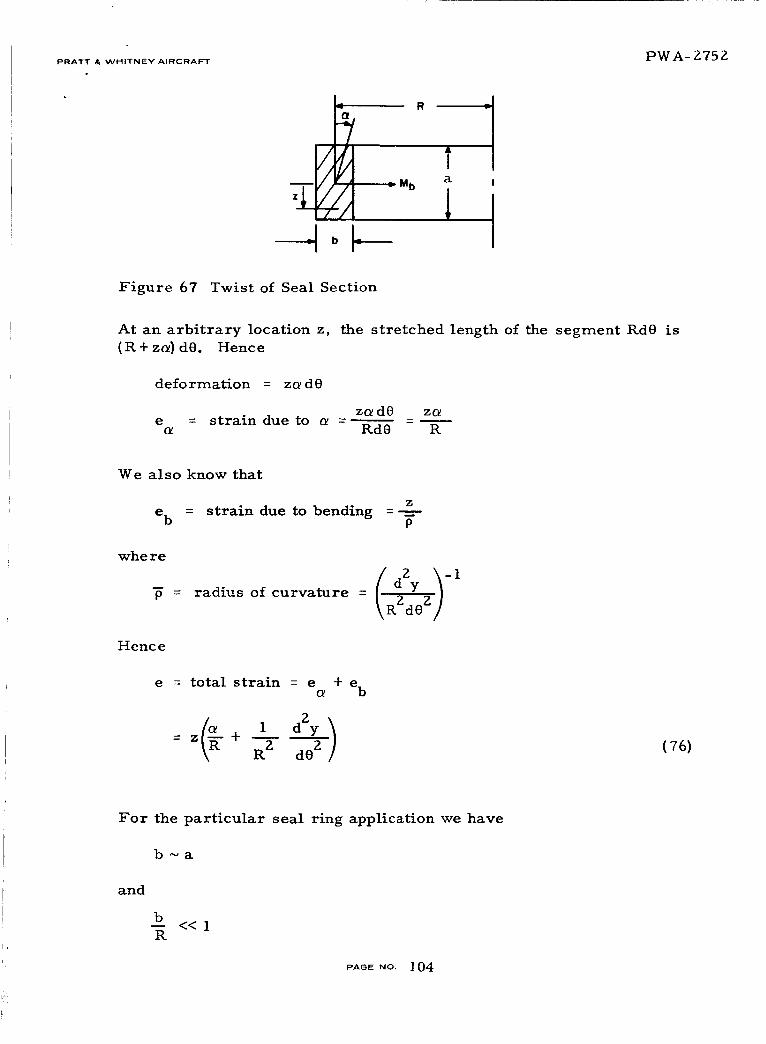
PRATT= W.,TNEY A,RC_AFT PWA- 2752
/;/ _M b
/-Z,
b
Ta
l
Figure 67 Twist of Seal Section
At an arbitrary location z,
(R+z_) dO. Hence
deformation = z_dO
e = strain due to _ =
the stretched length of the segment Rd8 is
z_d8 z_
Rd8 R
We also know that
e bz
strain due to bending =P
whe re
PdZy ._-
radius of curvature = _-R2--_02]
Hence
e = total strain = e + e_O/ b
(76)
For the particular seal ring application we have
b~a
and
b-- <<IR
PAGE NO. 104

PRATT & WHITNEY AIRCRAFT PWA_ Z75Z
where ~ denotes "of the order of".
Also, it is reasonable to assume that
Zdy
_b ~ y d@ Z
Thus
Z1 d y
R 2 dO 2
R
#)c_ b b <<
e_ R
R
Therefore, neglecting the strain due to ben_iJg,
to
e -- z --R
Equation (76) reduces
The expression for the bending moment is readily obtained,
a/Z a/2
M b = E e zbdz =-E -_- z bdz
-a/Z -a/Z
= M b =-EI _-_ (77)
Substituting (77) and (73) into (75) and neglecting terms of the order
of (b/R), we obtain
+ e"z p, \ aez + _ - k [y- 8o Cos 2 (e+cot)] -- pA_/
which is readily reduced to
6dz _ i___ =-K o
+ _ - Ku fZ -g--dO Z
C osZ (0 + cot) (78)
PAGE NO. 105

PRATT _- WHITNEY' AIRCRAFTPWA-Z75Z
where
YU _
b
kR3bK -
E1
f2 _ EI
> {79)
Here u is the non-dimensional transverse displacement, K, a stiffness
ratio, and f, a characteristic frequency.
Using the well-known formula
M = GI da (80)t p Kd@
with G = modulus of rigidity and Ip = section polar moment of inertia,
Equation (72} become s
2
oe z
: 0 (81}
where
E1
= G--Y-P
_2 = 12 Rb f2 _ G
,_ a2 + b 2 pR 2
{8Z}
Note that Equation (78) involves both u and _, while Equation (81) is an
uncoupled equation of _. Therefore, we would first solve Equation (81}
for a. Knowing the solution _, Equation (78) can be solved for u.
Assume separation of variables,
(O, t} : A(O) T(t) (83)
PAGE NO. 106

PRATT & WHITNEY AIRCRAFT
Substitution of (83) into (81) yields
T+X.T Z T : 0
PWA_Z752
(84)
and
-E+] _g_.+×A = (85)
where k is a positive constant.
The sotution of ( 8_ ) is
A(O) = al exp [ i0 _k -
+ a2 exp [-i O _k -
b )12 i_ tl
12 R -'t-] (86)
where a I and az are orbiting constants.
For a seal ring, the boundary conditions require that the solutions
be periodic in 8. Hence
b )k - 12 R "_ ] _ must be integers, or
b )X. - 12 R. -'1".] _ = n (n--0, 1,g .... ) (87)
Thus
×n = "E +] _;+ (n=O,l,Z,...) (88)
kn'S are the eigen values of the system.
The solution of (84) is then of the form
T(t) = _n { bnexp [iWntl +Cnexp [-iVnt3 }
where
v = f_fkn n
PAGe NO. 107
(89)
L
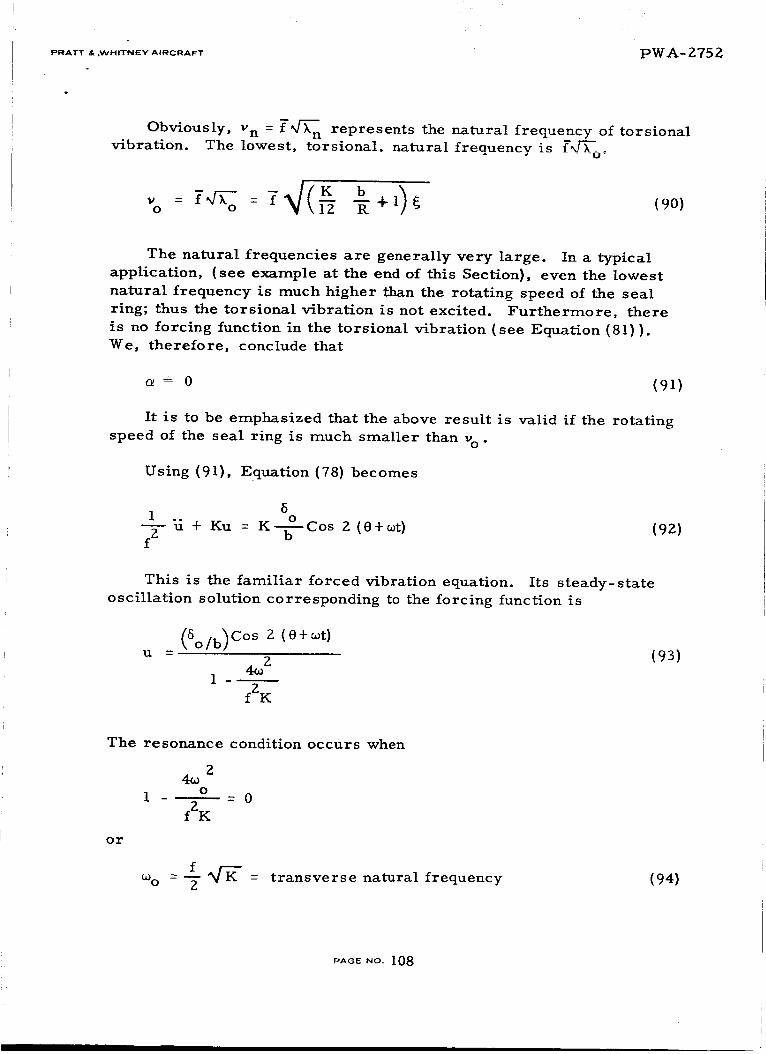
PRATT & ,WHITNEY A|RCRAFT PWA- 2752
Obviously, v n = f _f_n represents the natural frequency of torsional
vibration. The lowest, torsional, natural frequency is f-_f_o"
o IZ R +1 ¢ (90)
The natural frequencies are generally very large. In a typical
application, (see example at the end of this Section), even the lowest
natural frequency is much higher than the rotating speed of the seal
ring; thus the torsional vibration is not excited. Furthermore, there
is no forcing function in the torsional vibration (see Equation (81)).We, therefore, conclude that
= 0 (91)
It is to be emphasized that the above result is valid if the rotating
speed of the seal ring is much smaller than vo .
Using (91), Equation (78) becomes
61 o
f-_-_ + Ku = K--_---Coso 2 ({}+cot) (92)
This is the familiar forced vibration equation. Its steady-state
oscillation solution corresponding to the forcing function is
U
5o/b)COs 2 (O+(Dt)
4_ 21
f2 K
(93)
The resonance condition occurs when
24_o
1 o = 0
f2K
or
f _- = transverse natural frequency(D O --- -_-
(94)
.AGe NO. 108
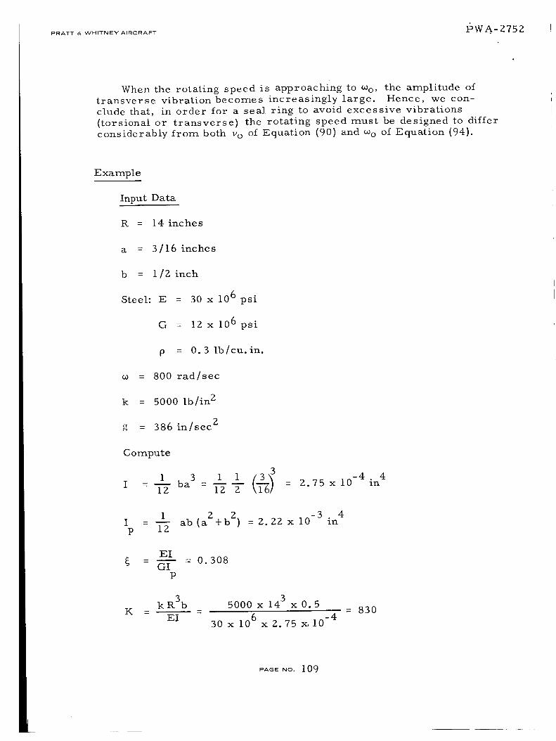
PRATT & WHITNEY AIRCRAFT I_)WA-- 275 Z
When the rotating speed is approaching to coo , the amplitude oftransverse vibration becomes increasingly large. Hence, we con-
clude that, in order for a seal ring to avoid excessive vibrations
(torsional or transverse) the rotating speed must be designed to differ
considerably from both wo of Equation (90) and coo of Equation (94).
Example
Input Data
I_ = 14 inches
a = 3/16 inches
b = l/Z inch
Steel: E =
G =
p =
30 x 106 psi
iZ x 106 psi
O. 3 Ib/cu. in.
= 800 rad/sec
k = 5000 tb/in Z
g = 386 in/sec 2
Compute
1 ba 3 1 1 3(]__)3I IZ IZ Z Z.75 x 10 -4
4o
_ - = In
I - 1 ab (aZ+b Z)p IZ
m __
-3 4= Z. ZZx i0 in
EI- 0. 308
GIP
k R3b
EI
5000 x 143 x 0.5
30 x 106 x Z.75 x. 10 -4
= 830
PAGE NO. 109

PWA- 275 2PRATT & WHITNEY AIRORAW'I"
f2 EI 30 x 106 x 2.75 x i0 4 04 1- - 2 = 8.28 x 1 2
• K3 O. 3 i-_(0.5) secp ab 2 3--_-x143x
32 G 12 x 106 1- - = 7.9x 10⁷
R.2 0 .___!3 2P 386 x 142 sec
From Equation (90) we can compute the lowest torsional natural
o R + 1 _ = 8.83 x 10³ 830 0.512 14 + 1 0. 308
= 9150 rad/sec
which is much greater than the rotating speed; thus the torsional vibra-
tion is not excited.
From Equation (94) the transverse natural frequency is
f _'K- _8"Z8x104 8%/_-0co =- = = 4150o 2 2
Thus,
5
Y 1.04 ou =-_ = -_- cosz(e+_t)
NOMENCLATURE FOR SEAL RESPONSE SECTION
a,b
a 1 , a 2
A
b n, C n
e
e a, e b
E
c r os s - s e ctional dimens ion
arbitrary constants in Equation (86)
cross-sectional area, ab
arbitrary constants in Equation (89)
strain
strains due to a and conventional bending moment
Young' s modulus
pA6e NO. 110
PRATT _ WHITNEY A,RCRAFT 15WA - 275 Z
f,Y
G
h
h
i
I
IP
Ir r' Itt
k
K
M
1,%
M t
q
qa
R
t
U
V
Y
Z
6, 6O
0
k
Characteristic frequencies defined in Equation (79) and
Equation (82) respectively
modulus of rigidity
gas film thickness
mean gas film thickness
4-i
moment of inertia
polar moment of inertia
mass moments of inertia
gas film stiffness per unit circumferential length
stiffness ratio defined in Equation (79)
mas s
bending moment
twisting moment
restoring force per unit circumferential length
restoring moment per unit circumferential length
mean radius of seal ring
time
Y
shear force
transverse displacement
coordinate in Figure 67
angular (torsional) displacement
defined in Equation (68)
circumferential coordinate
constant
PAGE.O. 111

PRATT &- WHITNEY AIRCRAFT PW z_- - Z75 Z
kn
vn
vo
eigen values of Equation (85)
torsional natural frequency
lowest torsional natural frequency
EI
GIP
density
radius of curvature
co rotating speed
O0
Otr ansve r se natural frequency
Seal Design
The work on compressor end and interstage seal design, beyond
the work on the primary seal performance, has been limited. Further
consideration of Concept V has led to the conclusion that it is very dif-
ficult or impractical to design. Review of primary seal performance
has not yet led to a clear selection of either type for the floated shoe
de signs.
Review of Concept V
One of the proposed concepts for the feasibility study is the thin
strip radial seal with a C-diaphragm as the secondary seal as shown in
Figure 68.
2
Figure 68 Thin Strip Radial Seal
! : !
Upon further examination, several serious drawbacks have been dis-
covered in this concept. First, the C-diaphragm must be flexible
enough to allow a radial displacement of 0. 032 inches between the sealand the housing for transient thermal growth. A continuous construc-
PAGE NO 1 IZ

PRATT & WHITNEY AIRCRAFT I°WA "- 2752
tion of the diaphragm like a semi-toroid is out of the question because
of its inflexibility. Consequently, the diaphragm not only has to be
made in sections, but also may have to be slotted in each section to
reduce the flexure stresses. Secondary sealing problems between
sections of diaphragm become quite difficult. The leakage through
secondary sealing surfaces is very difficult to control. Second,
sectionalized diaphragms have practically no load carrying capacityin the axial direction.
It is unlikely that an effective means can be added to maintainthe force balance in the axial direction.
In view of these shortcomings, the thin strip C-diaphragm radial
seal has been abandoned from any further considerations.
Primary Seal for Hydrostatic Floated Shoe Designs
A critical item for the floated shoe designs is their ability to
respond to runner deviations from true without excessive reduction in
film thickness. This is due to their relatively massive cross-section,
and is of particular concern for the two-side floated shoe which is a
radial seal and must accommodate radial motions at once per rev. of
0. 008 inches. It is anticipated that a hollow section may be necessary.
Since response is a function of primary seal stiffness, high stiff
hess is desired and a comparison must be made between the hydro-
static step seal and the orifice compensated hydrostatic seal. Such a
comparison is made in Figure 69 for a pressure ratio of R = 0.2 and
for a step width ratio of bl = 0.35 for the hydrostatic step, and_l = 0. 25
for the orifice compensated design.
0.6
05
Figure 69
O.4
0.3
_,_/O_IFICE - PICOMPENSATED, b I =O25, _'2 =02
,'I -- PI
STEP, b I =035, _2 =02
o/0.5 1.0 1.5 2.0 2.5
Comparison of Stiffness for Orifice and Step Hydrostatic
Seals
PAGE NO. I l 3

PRATT _ .WH,TNEVA,RCRAFT PWA- 2752
Figure 70 shows an evaluation of the efficiency of each typeof seal,
in terms of the ratio of stiffness to mass flow, as a function of b l, theI_ ¢_b c:LUUULWlrdLll I llestep ratio, opthnun_ ratio for the nyurostatic step _ .......
bl = 0.3. No optimum is indicated for the orifice compensated design,
but its maximum stiffness is several times that of the hydrostatic step.
The mass flows are nearly equal at equivalent b I.
Figure 70
• o2
- K',)MAXM
o
I/
/
I II
i
I
i
_EP
.2 3 4
bl = bl /b
Stiffness Flow Criterion vs Width Ratio
Referring again to Figure 69, the stiffnesses of the two designs
may be compared as a function of film thickness. The orifice com-
pensated design is much stiffer at the design point (maximum), but
falls off more steeply than the hydrostatic step design so that below
40 percent of the design film thickness, or above 225 percent, the
hydrostatic step is stiffer.
The need for supplementary hydrodynamic action at small film
thickness is apparent from this brief examination. As soon as cor-
responding data is available on the Rayleigh step design, a final
selection can be made. Sensitivity of the spiral groove pattern to non-
parallel surfaces makes it appear less desirable for supplementary
support.
PAGe NO. 114

PRATT & WHITNEY AIRCRAFT _E:)W-A"--_'75 2.
PRATT & WHITNEY AIRCRAFT PROGRAM
Approval of Screening Study Seal Concepts
Four compressor end seal and four stator interstage seal screening
study concepts were presented to NASA on October 7, 1965. NASA
approval was indicated in a letter dated October ii, 1965. This ap-
proval allowed the program to continue into the detailed feasibility
analysis, which is expected to require approximately four and one-
half months to complete. The approved seal concepts listed below
are shown in actual size and in exploded views with accompanying
descriptions in Figures 71 through 78.
E
26000
DIA REF
HIGH PRESSURE AREAS
]
LOW PRESSURE
AREAS
SECTION C-C
DESCRIPTION
Scheme A - Two Side Floated Shl)("
This is a hydrostatic supported segmented rin_ seal in which the- sl'_ments
are riF, id fl0atin_ shoes. A Compression spr£n_ h,_at(.d b,'tween ='ach s_-gra_nl
caases the seal rinp to retract at low air pressurt._. 3 h, ¸ primary _e_linp
face is (_f the hydrostatic step seal design. Th(. _'_ondary s_'alin_ i_ a[s(_ c_f
the hydrostatic type and a_lows th_ sho_ to follow _haft _r(,wth ;ind runout.
I
JVIEW IN DIRA
ViEW IN DIR B
Figure 71 Compressor End Seal Concept Scheme A - Ref PWADrawingNo. L-67714 Ref MTI Sketch-D-Z116
PAGE NO. 115

PW__-2752PRATT & WHITNEY AIRCRAFT
_IGH PRESSURE AREA
ENLARGED VIEW
SCHEME C
SECTION G-G
DESCRIPTION
Scheme C - One Side Floated Shoe
This seal is a hydrostatic supported segmented face seal in x_hich the seg-
ments are rigid floating shoes. The floating shoes are retained in the seal
carrier by an anti-rotation pin which also maintains a light compressive load
on the leaf springs. The light duty leaf springs and hydrostatic sec_ndary
sealing bet,,een the shoe and carrier alloxvs the shoe to follox_ lox_ magnitude
high frequency motion. The seal carrier _'hich has a piston ring for the
secondary sea] will follow, the full 0.4 inches of axial rnotit,n required. The
extension spring ties the sea] carrier to the fixed housing and causes the _ea]
carrier to retract at low air pressures. Wh_,n the primary seal is open a
labyrinth seal produces the required pressure differential h) close the s*.al
at the desired entTine operatin_ condition.
Figure 72 Compressor End Seal Concept Scheme C - Ref PWA Drawing
No. L-67714 Ref MTI Sketch-D-2134
PAGEUO. lt6

PRATT & WHITNEY AIRCRAFT PWA- 2752
SECTI ON H-H
I
I
SCHEME O
[
ENLARGED VIEW
EXTENSIONSPRING
DESCRIPT ION
Scheme D - Thin Strip - One Piece
The primary seal in this design is an orifice compensated hydrostatic
supported one piece continuous thin strip face seal. A leaf spring is
attached to the seal carrier and exerts a compressive f_Jrce on the thin
strip _hich is attached to the _eal carrier by guide pin-. Secondary
sealing betueen the thin Mrip and the carrier c,)n_lsts _)f a fu]ly floated
piston ring uhich permit_ the thin _trip to f,,Ih)t_ az_y l'Ut_,lttt or \_obhle
of the face. A coating is sho_tn x_hich provides a better rubbing surface
in case the thin strip contacts the face. The balance of tile construction
is similar to the one ride fl=_ating shoe.
Figure 73 Compressor End Seal Concept Scheme D - Ref PWA Drawing
No. L-67714 Ref MTI Sketch-D-213Z
PAGE NO. 117

PRATT & VyHITNEY AIRCRAFTPWA- 2752
%J%JC
ENLARGED VIEW
DESCRIPTION
Scheme E - Thin Strip - C Diaphragm
This seal is slmi_ar _o the one piece thin strip seal, the method of secondary
sealing being the primary change. This design utilizes a C diaphragm as the
secondary seal betx_ee_ the thi_ strip and seal carrier in place of the piston
riag and leaf springs. The design has been changed to incorporate compres-
sion 8prints in place of the extel_sio_ sprxngs used in txuo other face heal
designs, but the operation of the sea] is similar.
SECTION J-J
Figure 74 Compressor End Seal Concept Scheme E - Ref PWA DrawingNo. L-67714 Ref MTI Sketch-D-Z118
_,A_eNo. 118

PRATT & WHITNEY AIRCRAFT I::)I_T./_- Z 75 Z
I
VIEW IN DIRECTION A
f .It I
VIEW IN DIRECTION B
I
j !
SECTION C-C (ROTATED)
DESCRIPTION
Schen_e A - Two Side Floated Shoe
This is a hydrostatic supported seen_ented fine seal in whic_ t[xt" st'en_,mts
are rigid floatinp sh_es. A compression sprln_ located b_'tw('en each _eemenl
causes the seal ring to retract at 1(_,_ air pressure_. The prm_ary sealine
face is of the hydrostatic step seal design. The secondary sealine is also of
the hydrostatic type and allows the shoe to follow shaft erowth and runout.
SCHEME A
Figure 75 Stator Interstage Seal Concept Scheme A - Re£ PWA DrawingNo. L-67713 Ref MTI Sketch-D-2116
PAGE NO 119
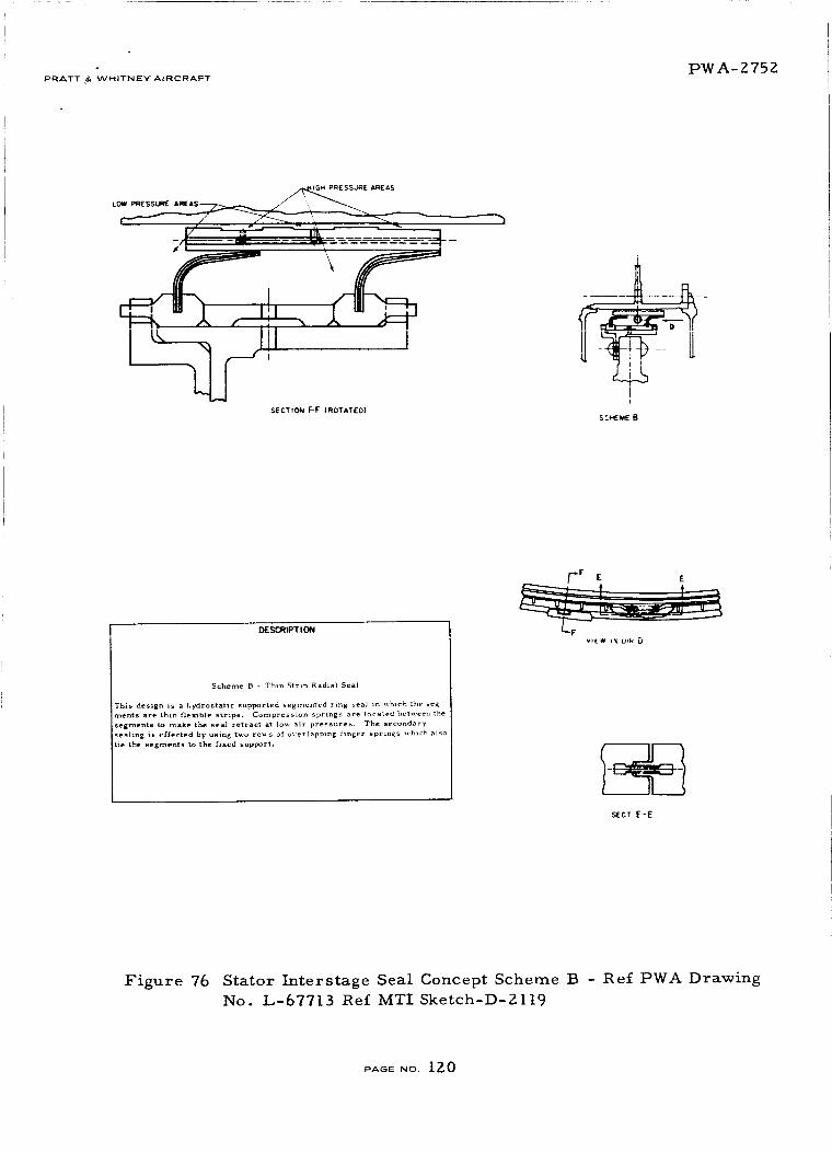
PWA-2752PRATT & WHITNEY AIRCRAFT
SECTION F'F (ROTATED)
JJ
SCME_tE B
DESCRIPTION
Scheme B - Thin Strip Radial Seal
This design is a hydrostatic supported segmented ring _eaJ in ,_hlch the seg-
ments are thin flexible strzps. Compression springs are located between the
segments to make the sea] retract at low air pressures, The secondary
sealing is effected by using t_o ro_s of o,-er]apping finger springs _,'hlch aiso
tie the segments to the fixed support.
f.,-F E E
VIEW IN DI_ D
SECT E-E
Figure 76 Stator Interstage Seal Concept Scheme B - Ref PWA Drawing
No. L-67713 Ref MTI Sketch-D-Zll9
_AGE NO. 120

PWA-2752PRATT & WHITNEYAIRCRAFT
COMPRESSION SPRING_ ENLARGED VLEW
SCHEME C
SECTIO_ G-G
DESCRIPTION
Scheme C - One Side Floated Shoe
This seal is a hydrostatic supported segmented face seal in which the seg-
ments are rigid floating shoes. The floating shoes are retained in the seal
carrier by an antl-rotation pin which also maintains a light extension load on
the leaf springs. The light duty leaf springs and hydrostatic secondary seal-
ing between the shoe and carrier allows the shoe to follow low magnitude high
frequency motion. The seal carrier which has a piston ring for the secondar_
seal will follo_ the full 0.4 inches of axial motion required, The extension
spring ties the seal carrier to the fixed housing and causes the seal carrier to
retract at lo'w air pressures. Whel_ the primary seal is open a labyrinth
seal produces the required pressure differential to close the seal at the
desired engine operatin_ conditions.
Figure 77 Stator Interstage Seal Concept Scheme C - Ref PWA Drawing
No. L-67713 Ref MTI Sketch-D-2134
PAGE No. 12 1

PRATT &'WHITNEY AIRCRAFT P'V_T._.. - ?,,75Z
F"7.J L._
H
m
U
ENL _G4ED VIEWSECTiON H-H
I I7
I
DESCR I PT t ON
Scheme D - Thin Strip - One Piece
The primary sea] in this design is an orifice cor_pensated hydrostatic
supported one piece continuous thin stri_ face seal. A leaf -pring _s
attached to the seal carrier and exerts a compre_,ix'e force ,,n the tl_in
strip _hich is attached to the seal carrier by guide pins. Secondary
sealing betxteen the thin strip and the carrter consists of a tully floated
piston ring xvhich permits the thin strip to follox_ any runout or ,aot,ble
of the face. A coating is sho,,n xxhich proxide_ a better rubbing surface
in case the thin strip contacts the face. The balance of the construction
is similar to the one side floating shoe.
I
SCHEME D
Figure 78 Stator Interstage Seal Concept Scheme D - Ref PWA Drawing
No. L-67713 1Ref MTI Sketch-D-Z13Z
PAGE NO. 122

PRATT & WHITNEY AIRCRAFT PWA-Z752
Compressor End Seals - PWA Dwg. No. L-67714 Rev A 4
Ref. MTI Figure Geom. ShapeType of Seal Scheme Dwg. No. No. Radial Face
Two side floated shoe A
One side floated shoe C
Thin strip - 1 piece D
Thin strip - C diaphragm E
SK-D-2116 71 X
SK-D-2134 72 X
SK-D-2132 73 X
SK-D-2118 74 X
Stator Interstage Seals - PWA Dwg. No. L-67713 Rev A 2
Ref. MTI Figure Geom. Shape
Type of Seal Scheme Dwg. No. No. Radial Face
Two side floated shoe A SK-D-ZII6 75 X
Thin strip B SK-D-2119 76 X
One side floated shoe C SK-D-2134 77 X
Thin strip - 1 piece D SI<-D-2132 78 X
Compressor end seal scheme B (SK-D-2119) is not included in this
listing; it was replaced by scheme E (SK-D-2118), as indicated in the
NASA letter of approval.
Dimensional Variance Considerations
The effects of th, following dimensional variances on the compressor
seal hydrostatic-hydrodynamic film thickness were considered.
i. Elastic
a. ) Centrifugal growth of rotating elements.
b.) Changes in slope of surfaces of rotating elements due to
combination of gas and centrifugal loads and variation in
centrifugal effect in adjacent rotor stages.
c. ) Change in slope of seal supporting surfaces due to gas
loads.
d.) Vibration of rotor and seal supporting members.
e. ) Effect of gyroscopic loads.
2. Tolerance
a. ) Rotor runouts.
b.) Squareness of seal supporting surfaces.
PAGENO. 123

PRAT_ = wH,-r_E,," A,RCRArr PWA- 2-75 2
.
c.) Flatness and surface finish of seal mating surfaces.
d. ) Tolerance build up.
The rmal
a. ) Distortion of seal mating surfaces due to thermal gradients.
b. ) Thermal growths.
c, ) Differential expansion,
d. ) Transient thermal effects.
It is Pratt & Whitney Aircraft's opinion that various elastic and thermal
dimensional variances may prove to be a major obstacle to overcome
in developing successful advanced compressor seals. The distortion of
seal mating surfaces due to thermal gradients is a particular concern.
To maintain an effective hydrostatic or hydrodynamic air film between
a seal and seal plate, it is necessary that the seal - seal plate inter-
face surfaces remain essentially parallel. With a compressor seal
operating at 850 ft/sec in 1200"F air, it has been estimated that several
horsepower are developed in shearing the thin air film existing at the
seal - seal plate interface. Localized heating of the interface surfaces
provides a temperature gradient across the seal and seal plate causing
them to curve ("heel") away from each other.
A possible solution to this problem being investigated by Pratt & Whitney
Aircraft is the use of pyrolytic graphite having the anisotropic property
of high thermal conductivity along one axis and low thermal conductivity
along another axis. Rapid dissipation of heat away from the seal - seal
plate interface should reduce the temperature gradient and minimize
the "heeling" condition. It is recognized that pyrolytic graphite acting
on itself as a seal - seal plate configuration may present excessive
wear problem.
Analytical Program
Pratt & Whitney Aircraft has been monitoring the MTI analytical effort
as specified in the prime contract.
PAQE No. 124

PRATT & WHITNEY AIRCRAFT PWA- Z75 Z
TASK II - COMPRESSOR END SEAL AND
STATOR INTERSTAGE SEAL
EXPERIMENTAL EVALUATION
This phase of the program provides for final design and procurement of
compressor end seals and stator interstage seals, design and fabrica-
tion of a test rig, and experimental evaluation of the compressor seals.
A test rig will be designed and fabricated to evaluate the selected com-
pressor end seals and stator interstage seals under simulated com-
pressor operating conditions. The test apparatus will simulate the
last stages of a full scale compressor including supporting members
and bearing system in order to faithfully duplicate structural flexibility
and thermal gradients.
The final design of the four compressor seal concepts selected for
experimental evaluation includes all calculations, material determi-
nations, analyses, and drawings necessary for seal optimization,
procurement and experimental evaluation.
The compressor end seals and stator interstage seals will be calibrated
in incremental steps at room temperature static conditions, room tem-
perature dynamic conditions, and subsequently over the full ranges of
temperature, speed, and pressure differential. Finally, the seals will
be subjected to endurance testing and cyclic testing at simulated take-off and cruise conditions.
PROGRESS
Design work was initiated in December on a full scale test rig.
PAGE NO. 125

PRATT & WHITNEY AIRCRAFT PWA- Z75Z
TASK III - COMPRESSOR STATOR PIVOT
BUSHING AND SEAL CONCEPT
FEASIBILITY ANALYSIS.
A feasibility analysis program is being conducted on stator vane pivot
bushing and seal concepts for application in compressors for advanced
air breathing propulsion systems. The first phase of this program is a
preliminary analysis and a screening of various seal concepts prior to
the selection of concepts for detailed feasibility analysis. The analytical
and all calculation, analyses, and drawings necessary to establish
feasibility of these selected concepts. This analytical program is sub-contracted to Mechanical Technology Inc. (MTI) of Latham, New York
and is being monitored by Pratt & Whitney Aircraft as required underthe terms of the NASA contract.
MTI SCREENING OF VANE PIVOT SEAL DESIGNS
The screening study of stator pivot seal concepts conducted by MTI is
presented in this section of the report. The material in this section
was prepared by Dr. H.S. Cheng, J. Bjerldie, and Dr. D.F. Wilcock.
The high pressure stators of compressors for advanced engines will
very likely incorporate variable vane stagger. The number of stages
requiring them is as yet unknown but the total will probably exceed 500.Each variable vane utilizes a pivot which penetrates the compressor
wall and even a little leakage out of each could represent a sizable
efficiency loss.
This section discusses the design and screening of a number of vane
pivot concepts. Some of these were in the original proposal, others
have been conceived since then.
All potential seal designs are compared against a seal that was built
and tested by Pratt & Whitney Aircraft (see Figure 79}. That design
was originated as a first modification of an existing design being used
in practice. A test rig was built by Pratt & Whitney Aircraft consisting
of this vane and its pivot in an airtight box. The only leakage possible
was out of the seal, so leakage measurements could be made. Only one
measurement was available during the term of the screening period, but
it served to indicate the extent of the problem. Thus, the candidate
seals could be rated as probably better or probably worse than the
existing seal.
IMAGE NO. 126

PRATT& WHITNEY AIRCRAFT Iz)WA- Z75 Z
ACTUATING ARM
/SPIRAL WOUND GASKET
AIR FLOWMETER
INLET AIR TEMPERATURE
4th STAGE VANE
/BEARING LOWER
BEARING UPPER/\\_ I"\\\ ,
\ \ \ i I
\\\ .
/ I
///,- / /
//////
///
r / /
//////
-.....RIG AND AIR-IN LINE WRAPPED
WITH RESISTANCE HEATING WIREAND INSULATION
Figure 79 Vane Pivot Seal Test Rig
The seals considered in this study, sketched in Fig_Jre 80 are:
Belleville washer
Coned-carbon rings with gaps
Fractured carbon rings
Metal spring
Seal packing
Lamiflex
PAGE No. 127

PRATT &-WHITNEY AIRCRAFT PWA-2752
all from the proposal, plus:
Internal actuation
External covers
Bellows loaded face seals
Spring loaded spherical seat seal
Close clearance bushing
Variations of each basic type were examined when there appeared
to be an advantage for a slightly changed design. First screening,
however, was done on basic types only.
Considerations for the screening were of three primary types:
(1) leakage rate
(2) functional
(3) logistics
Since the basic goal of the program was to reduce leakage, any
candidate that could not lead to low leakage was discarded. Tolerance
to dirt and load deflections plus inherent reliability were the two mainparts of the functional considerations. If a candidate seal was consid-
ered poor in this respect, it was discarded. Finally, weight, space,
actuation power, design simplicity, assembly, and servicing should
show as much gain as possible for a candidate to be an advantageoustype.
In all cases, comparison was made to the design used in the Pratt
& Whitney Aircraft leakage tests. Those new seals showing the most
potential gain over that design were considered the most promisingcandidates.
Eleven vane-pivot seal designs were compared on the basis of:
(1) leakage rate, (2) functional capability, and (3) logistics or servic-ing capability.
From this screening analysis, two designs have been selected for
the Feasibility Analysis Phase.
PAGE NO. ]28

PRATT & WHITNEY AIRCRAFT _:)WA _" Z75Z
Lw
I
J
wJJw
z:I:
i1:
_Jw w
..i m
w lzlm
u _ m
IE
r_
8o
< ZW _
___ _®
9_
z<> __ tn
K
&
<wol
u_ Kz
_1
w
o
u.
w _
m a.
>
_1u.
<.J
w
(_ (/1 _) o.z
_ _ _ _ o'_ ___ o
o z
',-T _,__1 6,) _: >< :3
oZ #
gl
0
0
°_--I
>
o
,r'4
PAGE NO. 12,9

PRATT & WH'TNEY AIRCRAFT PWA- _752,
Concept I. Spherical Seat Face Seal
Primary sealing is accomplished by a spring loaded spherical seat
i_ CL_ki(::LL.E:- ,:}ea .L_.I.E.. _,.[J.I..I.IE..L ,t_I.L. E7 U_c:l..,t l_li_ LU d. IJ,_',J.l. U• (:L.L_U (:::tL.L_ d._ ct LII_ U.,3L
the seating force of the Skinner type spring plus the thrust load created
by the air pressure acting on the vane.
Concept H. Single Bellows Face Seal
Primary sealing is expected by a bellows-supported face seal rub-
bing against the end of a bushing which is installed in the outer shroud
with an interference fit. The thrust loads created by air pressure and
spring forces are carried by a thru._t bearing located_ at the tip of the
vane.
Screening
Leakage Improvement
Two candidate designs were discarded because it could not be
shown that their leakage would be as little as the baseline design (the
Pratt & Whitney Aircraft test pivot seal). The Belleville washer will
have two leakage paths past the washer. Each path will be short, and
the effective clearance will not be any less than the baseline design.
The coned carbon ring seal with gaps has more leakage at a single gap
than does the baseline design.
Pratt & Whitney Aircraft leakage measurement of a single vane
during static, unloaded vane conditions was less than 0.004 SCFM at
94 psi and 400 °F. The loading on the thrust washer, including initial
torquing plus pressure load, is about 95 lbs. The leakage rate was
used to calculate the effective gap width of each of two leakage paths,
resulting in a calculated gap of 0. 000088 inches.
To compare the above measurements and design with the Belleville
washer, the load on the Belleville washer cannot be any greater than
for the baseline design, otherwise the actuating power will be greater.Also, since
T actuating = L x F = L x fN
Neither L nor f will be significantly different between designs, thus N
(normal force) for the Belleville washer seal has to be equal to or less
than that of the baseline seal to have equal or less actuating power.
With this loading, the effective gap between the washer and seal
will be approximately the same as the scale of roughness. Assuming
a good finish and a gap length equal to approximately 1/10 of the washer
thickness, the calculated leakage for a non-loaded vane through the
two paths is about 0.05 SCFM (63 micro inch finish), more than for the
baseline system.
PAGE NO, 130
PRATT & WHITNEY AIRCRAFT PWA-275 2.
The gaps in the coned carbon rings can be as much as .010 inches.
The leakage through such a gap can be as high as 0. l SCFM at the
same conditions as the baseline test. This is too great to allow its
further consideration.
Functional Considerations - The baseline design has the possi-
bility of getting dirt in the seal, encouraging cocking of the vane. Also,
since the vane can be cocked, the leakage rate can become quite high
under loaded vane conditions. Both of these possibilities pose prob-lems for the baseline seal.
The close clearance bushing exhibits the same problems. In this
case, however, the presence of particles between the bushing and vane
pivot can contribute to severe wear because of the close clearance,
and also can seriously increase the actuation power. Hence, this de-
sign was also rated as poorer than the baseline seal.
Reliability, as used in this report, relates to the opinion of the
design engineers as to the possibility of failure of the seal during ac-
tion of the vane. The fractured carbon ring, by its very nature, con-
sists of relatively fragile parts. This is considered sufficient to rate
it poorer than the baseline design.
The metal spring seal depends on close fit between the pivot and
the spring for sealing. This essentially means that it will rub. Rub-
bing can lead to wear and eventual penetration of the spring material,
especially since dirt can also deposit in the seal. Thus it was rated
lower than the baseline seal in evaluating reliability.
The Lamiflex seal depends for its operation upon an elastomeric
material bonding together a number of metallic washers. The stack
of washers plus elastomer extends for most of the length of the pivot.
However, the inner portion of the seal can be subjected to temperatures
approaching 1200°F since this is the compressor exit temperature.
Thus, at least a portion of some of the pivot seals will be exposed to
temperatures which are considerably above the usable temperature of
any available elastomer. Consequently, some of the pivots, if using
the Zamiflex seal type, will not be reliable.
Internal actuation can potentially reduce leakage simply by reduc-
ing the number of compressor wall penetrations. However, internal
actuation will necessitate the use of linkages exposed to hot oxidizing
gases. Also, the actuating torque would have to be transmitted to the
inner linkage through a limited number of vanes, potentially causingexcessive stresses and deflections.
Multiple labyrinths can conceivably make a good seal. However,
the number of segments of the seal must be large in number. The
segments of the labyrinth must, then, be made of thin sheet (only a few
thousandths of an inch thick). The probability of such labyrinths re-
maining non-rubbing is small when the vane is cocked while loaded. If
PAGE NO. 131

PRATT & WHITNEY AIRCRAFT PWA- 275 2
the segments rub, wear will occur, bending may occur, and generally
unknown effects can take place. Consequently, the seal cannot be con-
sidered reliable for long life. The labyrinth seal was therefore rated
a little lower than the baseline seal for reliability.
Logistic Considerations - The seal types which remain as candi-
dates after eliminating the seals mentioned in Leakage and Functional
considerations are:
(1) packed seal
(2) external covers
However, these seals must be evaluated with respect to weight, space,
actuation power, design simplicity, assembly, and servicing. These
are factors which affect the installation and overall system, but which
are not determinant as to the "workability" of the concept. The seal
is acceptable to the degree that weight, space, and actuating power are
kept down, and design simplicity, assembly, and servicing are kept
uncomplicated. For want of a better single term, these are lumped
under the word "logistics"
Weight of all the remaining concepts will be about the same except
for the external cover type seal. This seal requires a separate "pres-
sure skin" outside of the actuators and pivots. However, it is prob-
ably the most straightforward way of keeping leakage low, and despite
the fact that it rates poorly on weight, space, and servicing, it may
eventually be the least costly method.
Space requirements of all syste1_qs reznaining under considerationare all about the same.
Only the packed seal will potentially exhibit higher actuating power
than the baseline seal. Calculations indicate the possibility of low
friction after "wear in",but past experience belies these results. Since
design for packed seal actuating power depends upon an empirical de-
sign approach, past practice must be relied upon. Thus, it must be
conceded that actuation power for packed seals may be too high to be
acceptable.
The packed seal will also exhibit a difficult assembly and servicing
requirement. The baseline seal is torqued down upon assembly so that
unloaded actuating torque is 1. 5 in-lbs. The packed seal must likewise
be preloaded by torquing the seal upon assembly. However, the seal-
ing ability of the packed seal depends upon the packing pressure against
the vane shaft. The compressor pressure load does not markedly as-
sist the sealing as it does for the tested seal. Thus the packed seal
adjustment is slightly more sensitive to initial adjustment.
The packed seal must be "worn in" without loss of sealing ability.
This, too, would complicate the assembly and servicing, however,
since wearing in would have to occur before final installation.
RA_E NO. 132

PRATT & WHITNEYAIRCRAFT PWA-2.752.
External covers over the baseline seal would require additional
time and effort in cover removal and replacement at each servicing.
Since it is meant to be a reasonably tightly sealed unit itself, this does
constitute assembly and servicing complexity.
Bellows loaded face seals do not have to be preloaded by torque
adjustment; they can be assembled as a cartridge. Thus, they repre-
sent a gain in assembly and servicing ease.
The spring loaded, spherical seat face seal likewise need not be
adjusted upon installation. However, its assembly is more sophisti-
cated because one part of the seal has to be firmly assembled to the
vane shaft. These two effects tend to counterbalance each other so
far as assembly and servicing is concerned. Consequently, this seal
was rated equal to the baseline seal.
Screening Chart
The results of the foregoing considerations are displayed on the
screening chart, Table XII. All seals are rated with respect to thebaseline seal:
0 is the same rating
+ is a higher rating
- is a lower rating
TABLE XII
COMPARISON OF VANE PIVOT SEAL CONCEPTS
Seal Type
Baseline design
Belleville Washer
Coned carbon rings
with gaps
Fractured carbon ring
Metal spring seal
Seal packing
Close clearance
bushing
Lamiflex
Internal actuation
External ( overs
Bellows or springand face seal
1) single bdluws
2) 2 bellows
3) S'pherical seat
Multiple labyrinth
o o_U
0
-l/z
-1
+1
_-1
+1
_-1
+2
¢i
i-i
*I
+1/2
i Functional Considerations
¢z
v 0a
0
,p
Tolerance
to Dirt
and Load
Deflections Reliability
0 0
-L -1
0 -1
+l +1
-1 0
_l -1
+1 -1
*1 0
+1 0
+1 +1
,l/Z -1/2
l Logistic Considerations
!_ Act .... S i nD:!tz_'1g int y ,
g _ I I tion Assembly,
_e_ [Weight I Space Power Servicingi
0 0 : 0 0 0
+2 0 0 -1 -1/2
g_
+1 -1 0 0 -1
+1 0 0 0 +1/2
+Z 0 0 0 +1/2
+2 0 O 0 0
L ............
:::Excluded from further consideration because of negative ratings
o
i i
0 I 0 I
-I i/zl+l 1/2 I
-2 I 0 I
+l/Z 1_2 i/21
+1/2 1+3 112 I
0 1+3 I
PAGE NO. 133

PRATT & W_,TNEY AIRCRAFT PWA-2752
Most rating numbers are _- 1 since only a trend is meant to be indi-
cated. Where an effect is known to be strong the rating can be_- 2.
Where an affect is suspected to be quite weak the rating is indicatedas+ i '"/L.
As already implied, some seals were dropped from consideration
as a result of specific negative rating. Any seal having a zero or nega-
tive leakage rating was not considered further - independent of how
good it may be with respect to other considerations. Also, any seal
having a negative rating for either of the functional considerations was
dropped - independent of how good the seal might be from otherconsiderations.
Logistic ratings could be either positive or negative and remain
in contention since these considerations were not meant to be "go" -
"no-go" ratings.
As a first approximation of the value of a seal, all rating numbers
were summed to provide an overall rating. However, this was only
done for those seals remaining in final contention. As indicated in
Table XII, the order of preference among seals is as follows:
Double bellows loaded face seal
Spherical seat, spring loaded face seal
Single bellows loaded face seal
Packed seal
External covers
It should be re-emphasized here that the external covers would
be the simplest overall solution ifthe additional weight, space, assem-
bly, and servicing complexity can be tolerated. Since this study must
consider these aspects, however, the external cover solution appears
poorest of the acceptable designs.
It should also be pointed out that the slight difference in design
between the single and double bellows seals really represents two
variations of a single concept and should be considered as such.
The packed seal presents a gain at the expense of an uncertaintyin its torque characteristics. Hence, it may not be as desirable as
the rating number would indicate.
The seals with the highest rating numbers therefore represent the
best initial concepts to be carried into the feasibility analysis.
I. bellows loaded face seal
2. spring loaded spherical seat face seals.
PAGE NO. 134

PRATT & WHITNEY AIRCRAFT PWA-2752
MTI VANE-PIVOT SEAL FEASIBILITY ANALYSIS
The feasibility analysis of stator pivot bushing and seal concepts
conducted to date by MTI is presented in this section of the report.
In the Screening Study just presented, it was mentioned that the
two seals still under consideration are the bellows-loaded face seal and
the spring-loaded spherical seat seal. Feasibility Analysis work since
NASA approval of the Screening Study Concepts has involved refine-
ment of the concepts and review for comments and suggestions with
seal manufacturers. The final designs are being prepared in the lightof these comments.
A sketch of a single bellows seal design, as shown in Figure 81,
was sent to Sealol, Gits, and Cartriseal for comments and recom-
mendations. Sealol responded with the sketch shown in Figure 82.
This design incorporates a retaining ring over the seal rather than
trapping the pivot between the housing rings. A final design will have
to include the latter feature rather than the ring.
Sealol recommended the use of aluminum oxide or tungsten carbide
rather than graphite as the face material. These materials will hence-
forth be considered as alternatives to graphite or boron nitride. Either
of the latter will have much lower friction than the ceramics.
Because Sealol recommended the use of a larger bellows than de-
sired, further consideration will be given to a machined bellows of
only half or one convolution for the final design. This is made neces-
sary because the circumferential spacing of the vane-pivots at a given
stage is so tight.
Response from the other two vendors has been of marginal benefit.
Figure 83 shows another version of the bellows-loaded face seal,
incorporating the thrust face at a point partway out on the pivot shaft.
Some thermal advantage can be achieved by doing this because the tem-
perature can be between 50°F and 100°F cooler than at the inside. This
much temperature advantage could make graphite coating appear more
feasible than at present. There would be no advantage gained for theother candidate face materials.
PAGE No 135

PRATT & "WHITNEY AIRCRAFT PWA- Z75 Z
F_THRUST
LiI
FACE
EAL
Figure 81 Single Bellows Seal
Figure 8Z Single Bellows Seal, Sealol Design
PAGE NO. 136

PRATT & WHITNEY AIRCRAFT Iz)W _. - B75 2
_THRUSr F_C_
Figure 83 Single Bellows Seal, Relocated Thrust Face
A new scheme for the spherical seat face seal is being considered.
The original one is shown in Figure 84. The thrust is now to be taken
on a shoulder similar to that of Figure 83. The spherical seat seal is
at the outer end of the pivot shaft, and a machined bellows is to be fit-
ted between the housing and the seal.
All these variations of the two designs are to be considered in de-
tail during the next report period. An attempt will be made to incorpo-
rate the use of graphite into these designs as the face material. Mate-rials users and vendors will be contacted for further information as
necessary. In the event that graphite is finally deemed impractical,the materials to be considered as alternatives will include:
(1) Boron Nitride
(2) Tungsten Carbide
(3) Aluminum Oxide
(4) Chrome Oxide
PAGE NO. 137

PRAY- = W_TNE¥ A_RCRA_T PWA -?_752
PRATT & WHITNEY AIRCRAFT PROGRAM
Two stator vane pivot bushing and seal screening study concepts
were approved by NASA on October 7, 1965. This approval allowed
the program to continue into the detailed feasibility analysis. The ap-
proved seal concepts listed below are shown in exploded views with_r_- n A r-
Doaccompanying descriptions in _igures and 8 ...... C _'_igure
86) is an alternate for Scheme B.
Scheme A
Scheme B
Scheme C
Spherical Seat Face Seal
Single Bellows Face SealDouble Bellows Face Seal
As directed by NASA, no feasibility analysis effort will be expended on
the double-bellows seal design (Figure 86) unless it is determined that
the sealing face surface in the single bellows seal is subject to distor-
tion and leakage.
Pratt & Whitney Aircraft has been monitoring the MTI analytical effort,
as specified in the prime contract.
PAGE NO. 138

PRATT & WHITNEY AIRCRAFT 1Z)'V_ "- 2752
ERENCE
SILVER PL#
ALL OVER
3
ENLARGED VIEW
O OOl-O 004 L
/
__J_E_ 'NTERFERENCE F'T',i F"__
_ _fNTI -TURN FEATURE
-/" - il _ f
"N._...__ _._..-_"
DESCR1 PT ION
Schei_e A - Spherical Seat Face_ Seal
!n this design the primary seal is effected by a sprin_-Ioaded spherical seat
_ace seal. The spherica£ face also acts as a thrust bearine to absorb the
_eatin_ force of the Skinner sprin_ plus the thrust load created by the air pres-
_ure actin_ on the vane. Both of the spherical surfaces will be plated with a
_aterial havin_ a low coefficient of friction to reduce actuatin_ torque and
_revent _,allin_.
FL
SEALSILVER PLATE
/
VIEW IN DIRECTION A
_:.Y_.:=_
iJi iI'i._i L_._J_]l.C L._J
Figure 84 Stator Pivot Seal Concept Scheme A - iRef PWA Drawing
No. L-67563 Ref MTI Sketch of 9- 14-65 byH. Jones
PAGE No. 139

PRAI-T & WHITNEY AIRCRAFT PW-_ - 2 75 2
INTERFERENCE
CARBON OR CERAMIC
INTERFERENCE
FIT
SCHEME B
DISCRIPTION
Scheme B - Sin{,l_ Bello_s F_ce Seal
This design is similar to the double bellows seal, except that only one sealinp
face is hello,_.s supported. The other sealin_ face is formed by the end of a
bushin_ which is installed in the outer shroud with an interference fit. The
main advantage of this desien over the double bellows desien is that it has
fewer parts.
SCHEI_E B
Figure 85 Stator Pivot Seal Concept Scheme B - Ref PWA Drawing
No. L-67563 Ref MTI Sketch of 9-1-65 by E. Belawski
PAGE NO. 140

PRATT & WHITNEY AIRCRAFT _PW'.,A - Z 75 Z
/
INTERFERENCE_FIT
\
\
\WELDED BELLOWS
/
SCHEME C i
DESCRIPTION
Scheme C - IDc)uble Betlc_s Face Seat
This desifn offers maximum tolerance to dt'flections in that both sealine sur-
faces are supported by a t_elded metal bello_s. The seal pl_'ces are n_ad_' of
a material such as carbon or ceramic and are retaint'd in the belIo_s asst m-I
bly by an interference fit. Tilt thrust loads created by air pressare and
sprine forces are carried by a thrust bearine located at tht" tip ot the t ant'.
SCHEME C
Figure 86 Stator Pivot Seal Concept Scheme C - Ref PWA Drawing
No. L-67563 Ref MTI Sketch of 9-5-65 by E. Belawski
PAGE NO. 141

PRATT & WHITNEY AIRCRAFT PWA-,?,752
TASK IV - PIVOT BUSHING AND SEAL
EXPERIMENTAL EV A T .TTA _I_T('_]%T
This phase of the program provides for final design and procure-
ment of bushings and seals, design and fabrication of a test rig, and
experimental evaluation of bushing and seal assemblies.
The final design of the two selected concepts for experimental
evaluation includes all calculations, material determinations, analyses,
and drawings necessary for pivot bushing and seal optimization, pro-
curement, and experimental evaluation.
A single vane test rig will be designed and fabricated to evaluate
the two selected pivot bushings and seal designs under simulated oper-
ating conditions for the last compressor stage. The vane and actuating
mechanism are to be applicable to current advanced engine practice.
The pivot bushing and seal assemblies will be calibrated in incre-
mental steps over the full pressure and temperature range, with a
maximum pressure of 135 psi and a maximum temperature of 1200°F.
The seals will be subjected to a cyclic endurance run of at least 40
hours duration following a test program which provides for simulation
of take-off (20 hours) and a cruise (20 hours) conditions typical of ad-
vanced engine designs through duplication of:
Compressor stage air temperatures
Supporting structure geometry
Supporting structure temperatures
Pivot movements as required for the vanes
Pivot loading (mechanical loading to simulate air loading
is acceptable)
Compressor stage pressure drop
per
ient
The pivot movement will be minimum of 13 degrees at 10 cycles
minute; the pivot loading will include a vibratory load to a conven-
± 15% of the steady load.
PR OGR ESS
Preliminary design work is continuing on a test rig in which the
vane pivot bushing and seat experimental evaluation will be conducted.
Further investigations were made of the methods of applying the re-
quired steady state and vibratory loads to the vane pivot seals. Since
the air leakage rate is expected to be too low to maintain the test rig
temperature of 1200°F, it appears desirable to incorporate electric
cartridge-type heaters in the body of the rig.
PAGE NO. 14Z

PWA- 2752PRATT & WHITNEY AIRCRAFT
An analysis of a current advanced engine has indicated that the
minimum axis bending moment of the last stage stator vane was 19. 8
inch-pounds at the outer diameter. The mechanical load required to
simulate this air load was calculated, using the formula for a guided
cantilevered beam, to be 21.85 pounds when applied to the lower pivot.
The deflection of the vane at the lower pivot was calculated to be 0.0012
inches with the load applied perpendicular to the major axis. The load
will be applied through a coil spring in the test rig. The steady state
load will be set by compressing the spring to a predetermined height.
The vibratory load will be superimposed by varying the deflection =E by
the use of an eccentric drive. The frequency of the vibratory load will
be 30 cps. The stress in the vane will also be monitored during the
test by attaching a strain gage to the upper part of the vane.
According to contractua] agreement, no hardware will be procured
until NASA approval of the design is obtained.
PAGE No. 143

PRATT & WHITNEYAIRCRAFT
MONTHS
TASK
SCREENING STUDY
NASA APPROVAL
DETAILED ANALYSIS
NASA APPROVAL
TASK _Z"
RIG DESIGN
NASA APPROVAL
SEAL DESIGN
NASA APPROVAL
HARDWARE PROCUREMENTRIG
SEAL NO. I
SEAL NO. 2
SEAL NO. 3
SEAL NO 4
EVALUATIONSEAL NO. I
SEAL NO 2
SEAL NO. 3
SEAL NO. 4
MILESTONES
PROGRESS REPORTS
MONTHLY PROGRESS REPORTS
SEMIANNUAL REPORTS.t
SUMMARY REPORT
2 3 4 5 6
-ii-=_ _
I
i®
d A S 0 N D|
-- 1965 _-
Figure 87 Compressor Seal
/

COMPRESSOR SEAL DEVELOPMENT
PROGRAM SCHEDULE AND MILESTONE CHARTCONTRACT ._3-7605
7 8 9 I0 II
I
°1I
• • • I •
F
12 13 14 15 16 17 18 19 20 21 22 23 24 2
' I
S 0 JM A M J J A N D
1966
F M
pment Program Schedule and Milestone Chart
___._1_A M d
1967_

PWA-2752
26 27 28 29
II
®
iiili-
A S 0 N
I9/15
30 M ILESTONES
I. TASK I - COMPLETE
2. TASK lIT - COMPLETE
3. TASK 117- COMPLETE
4.TASK I - COMPLETE
5. TASK lv - COMPLETE
6. TASK i'C- COMPLETE
Z TASK ]I - COMPLETE
8. TASK 1T -- COMPLETE
SCREENING STUDY
SCREENING STUDY
DETAILED ANALYSIS
DETAILED ANALYSIS
RIG DESIGN
SEAL DESIGN
RIG DESIGN
SEAL DESIGN
9. INITIATE TASK _Z TESTING
I0 INITIATE TASK rr TESTING
I1. TASK I_Z- COMPLETE EVALUATION OF ONE, STATOR PIVOT SEAL
12.TASK it - COMPLETE EVALUATION OF ONE: COMPRESSOR END SEAL
13.TASK I[ -- COMPLETE EVALUATION OF ONESTATOR INTERSTAGE SEAL
!I4SUBMIT SUMMARY REPORT FOR NASAA P PROVAL
LEGEND
, WORK PROJECTED
, _---3 REVISED WORK PROJECTED
WORK ACCOMPLISHED
I I WORK COMPLETED EARLYI
I
D
PAeE No. 144
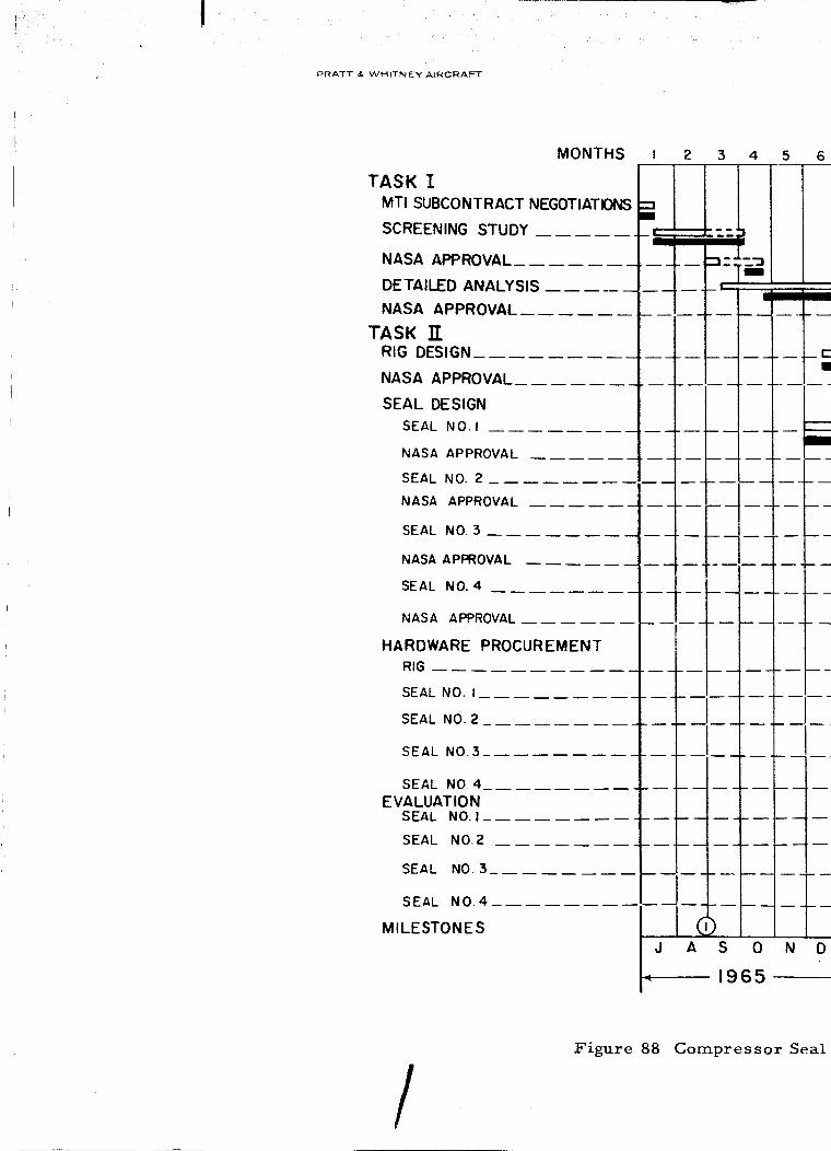
PRATT & WHITNEY AIRCRAFT
MONTHS I 2 3 4 5,
TASK I
MTI SUBCONTRACT NEGOTIATIONS
SCREENING STUDY
NASA APPROVAL
DETAILED ANALYSIS
NASA APPROVAL__
TASK ITRIG DESIGN_
NASA APPROVAL_
SEAL DESIGN
SEAL NO. I
NASA APPROVAL
SEAL NO. 2
NASA APPROVAL
SEAL NO. 3
NASA APPROVAL
SEAL NO. 4
NASA APPROVAL
HARDWARE PROCUREMENT
RIG
SEAL NO. I
SEAL NO. 2
SEAL NO.3_--.
iII
,!51 ,
SEAL NO. 4
EVALUATIONSEAL NO. I.....
SEAL NO.2
SEAL NO. 3__
SEAL NO.4
MILESTONES
/Figure 88 Compressor Seal

COMPRESSOR SEAL DEVELOPMENT
PROGRAM SCHEDULE AND MILESTONE CHARTCONTRACT NAS3- 760"5
7 8 9 I0 II
112 13 14 15 16 17 18 19 20 21 22 23 24
_----r
I
J F M A M J J A S 0 N DIJ1966 ,.i-_
F M A M J
1961
:)evelopment Program Schedule and Milestone Chart
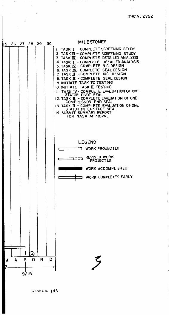
26 27 28 29
PWA-2752
M I LE STONES
I. TASK I - COMPLETE SCREENING STUDY
2. TASK1Tr-COMPLETE SCREENING STUDY3. TASK]E- COMPLETE DETAILED ANALYSIS4. TASK I - COMPLETE DETAILED ANALYSIS5. TASK 7E - COMPLETE RIG DESIGN6. TASK "IV -COMPLETE SEAL DESIGNZ TASK Tr -COMPLETE RIG DESIGN8. TASK 1T - COMPLETE SEAL DESIGN9. INITIATE TASK _Z TESTING
I0. INITIATE TASK 1T TESTINGII. TASK ]_- COMPLETE EVALUATION OF ONE
STATOR PIVOT SEAL12. TASK ]_ - COMPLETE EVALUATION OF ONE
COMPRESSOR END SEAL13. TASK IT - COMPLETE EVALUATION OFONE
STATOR INTERSTAGE SEAL14. SUBMIT SUMMARY REPORT
FOR NASA APPROVAL
LEGEND
I i WORK PROJECTED
I =-;3 REVISED WORKPROJECTED
_1_ WORK ACCOMPLISHED
I I WORK COMPLETED EARLYiI
A
9/15
PAeE NO. 145

!
PRATT & WHITNEY AIRCRAFT PWA-2752
APPENDIX A
A seal of the type presented in this study permits a certain leakage
flow. This leakage can be costly in both the power it takes to compress
the air, as well as the reduction in turbine flow. In this project, the
object of the study is to optimize the design in every respect. One of
the obvious requirements is to reduce the leakage flow, while maintain-
ing sufficient film thickness to assure successful mechanical operation
without detrimental contact between rotating and stationary parts of theseals.
In opposition to this requirement is the fact that, as the film
thickness is reduced, the drag power consumption of the seal increases.
These are the factors that must be optimized.
LEAKAGE FLOW
In all seal designs the flow is computed on the basis that the leak-
age area is a slit as shown in Figure 89.
PL
--- L 4 Ph
't
Figure 89 Schematic of Leakage Area Slit Assumed for Leakage Flow
Computations
PAOE NO. 146

PRATT & WHITNEYAIRCRAFT PW.A-2752
Then
Q
whe re
Q3
= Vol. of air at conditions PIT1 in /sec
b = length of slit inches
= 27,25_
_P = Pressure difference Ib/in 2
L = length of leakage path inches
= 1/2 inch
= viscosity of air at conditions PIT1 lb. sec/in 2
-_ 5.69x l0 -9 lb. sec/in 2
h = fiIm thickness inches
(#.-1)
= .0003 to .001 inches
Then
Qin 3 = 27,25_(AP h 3) x 109sec 12x5.69xl/Z
3
Q = Z.5 x 109 (AP h 3) in (A-la)sec
Convert the volume flow Q to weight flow by computing the density
from the gas law
PV : RT (A-Z)
then
P1
Density p - lbs-/ft 3RT 1
PAGe NO. 147

PRATT &.WHITNEY AIRCRAFT PWA- 2752
R = Universal gas constant for air
= 53.3 (ft. lbs.)/(lbs. OR)
2P1 = Inlet pressure lbs/in.
= 144P1 lbs/ft 2
= Inlet temp. °R
the leakage flow is
T 1
Finally,
W pQ lbs/sec when the units are consistent
P1Q
.'.W - 640 T 1 lbs/sec (A-3)
COMPRESSION POWER
The pumping power required to compress the air from some lower
pressure to the pressure level at the seal is given by the following
equation
W n F n-I ] 1
I-IP = -- x -- x RT LJR 1 x 550(A-4)
'I n-i o c n
where
HPcomp
W
'I
= compression power - horsepower
= flow lbs/sec
= compression efficiency - dimensionless
= .86
n
R
Exponent of the adiabatic compression process
1.4
ft- ib53.3
lb - OR
PAGE NO. 148

PRATT & WHITNEY AIRCRAFT PWA- Z752.
TO
= Initial air temperature °R
= 560
Rc
55O
Compressor pressure ratio
-- Z0
= Work rateft Ibs / sec
H. P.
Then
14 I 86]HPcomp .4 x 53.3 x 560 g0" - 1
Wx
550 x 86
HP = 298W Ibs/seccomp
(A-4a)
SEAL DRAG POWER
The drag power of the seal is
HP = FxAU2
drag 6600 h
2A = area of the seal surface, in
= 27.25 Trx I/Z
U = relative linear velocity of seal surface
x 27.25 x 8000= = 950 ft/sec
720
in/sec
(A-5)
h = film thickness
= .0003 to .001 inches
Then
HPdrag
5.69x27.Z5_x 1/2 x(950 x 12) 2.
6600 x 109 h
5.Z
103h
PAGE NO 149

PRATT & WHITNEY AIRCRAFT PWA-- 2.75 2.
Example
Compute the optimum film thickness for the compressor end seal,
where the physical dimensions are as shown in Table XlII. First com-
pute, (Ref. Equation A-la)
Q = 2.5 x 10⁹(AP h 3) in3/sec
Assume that Ap = 150 lbs/in 2
Then
Q 2.5 x l09 h 3= x 150
Q = 375 x 109 h 3
And convert the volume flow to weight flow (Ref. Equation A-3)
P.Q
W = 640T 1 Assume T 1 = 1600°R
W
150xQ
640 x1600
1.465 Q
10 4
Third, from this tabulated value, the compression power can be com-
puted as follows, (Ref. Equation A-4a)
HPcomp" 298W
Fourth, the drag power for the seal is
HFdrag
5.2
10 3 h
pAGE NO. 150

PRATT & WHITNEY AIRCRAFT I=)WA - 275 2
H
X
_q
<
<
b0
Z
O00o0
OUI
ZO
oO
Z
<uI-4
b0
II
II
ooo(90 _
H
U
03
cq
c_
c_
c_
LF_
O0
oO
c_
¢q
I
o
×
I
O
L_
O
O0
CO
-.D
0
0
N
I
0
Cq
I
o
e_
0",,
L_
eq0
I
o
_q
e',.l
I
o
eq
0
0
o
eq
I
0
X
ooo
c_
I
0
o
PAGE NO. 1 5 1

PRATT _. ',NHITNEY AIRCRAFT
PWA-2752
APPENDIX B
SOLUTION OF A HYBRID LUBRICATION PROBLEM
WITH RAYLEIGH STEPS AND CYCLIC BOUNDARY CONDITIONS
The problem is to solve Reynolds Equation in a field where the
clearance function could present discontinuities. Also, the possibility
of complicated boundary conditions should be easily accommodated.
The Reynolds Equation is written in two forms: the first, suitable
for parts of the field where the clearance varies smoothly and the sec-
ond, for clearance discontinuities. These are, respectively
Ve (# VQ - A _H) = 0 (B-l)
and
where
V
i, j
X, Y
L
H
C
Q
P
A
_t
VQ - A_,)e _i d_ = 0 (B-Z}
a
:i-b-A+ j%-fthe base vectors of the coordinate system.
X Y= dimensionless coordinates -
L' Z
typical length = length of side parallel to X axis
hdimensionless clearance =
C
= typical clearance
= p2
ambient pressure
6_L V2
Pa c
= viscosity
152PAGE NO.

PRATT & WHITNEYAIRCRAFT PWA- 2752
V = velocity = V i + V jx y
= element of a closed loop curve in the field
= outward normal to above mentioned curve
The possible boundary conditions are:
a, Fixed pressure such as at the outer boundaries exposed to
atmosphere.
8P 8P
b. Lines of symmetry where _ or -0Y
c. Periodicity conditions in X or Y.
The numerical solution of the problem is executed on a rectangular
grid of Mx N points. Let i and j represent the matrix indices corres-
ponding to the X and Y coordinates respectively.
Equation (B-l) is written in the following form:
2Q "VH A ,VQ 0 (B-3)3V • VQ +vZQ _ A pH 3 - PH a -
By using the approximations
i
vQ = (Qi+l,j- Qi-/,j ) ZAX + (Qi, j+l - Q" ) J1, j-1 gAY
and
V2 Q : Qi+l,j m 2Qij + Q i-l, j + Qi, j+l - ZQij" + Q'_,j-I
(z x)2 (,,y)Z
and by computing H and its derivatives from analytical formulae,
Equation (B-3) becomes
ZI (Qi, j Qi+l,j Q" "' Q" Q" I) = 0 (B-4)' ' i-i, 3 i,j+l' 1,j-
Where_ lindicates a linear algebraic operator. The variable P is
considered to be a coefficient so that the problem is solved by iteration.
An initial distribution of P is seiected, Q is solved for by linear methods,
and then P = _-Q provides an improved guess. This procedure is
known to converge very rapidly.
153PAGE NO.

PWA-2752PRATT & .WHITNEY AiRCrAFT
For points on clearance discontinuities, Equation (B-Z) must be
used. The integration path is taken to be a rectangle of sides AX and
AY centered at the point in question. Equation (B-Z) becomes
2 8X
i+I/2,j
i,j+l/2(H3 oQ A AY = 0AY + _ oY Y
i-1/2,j i,j-l/2 (B-5)
where
%Q
_X
i
_X (Qi+l, j - Qij ) etc.
i+I/Z,j
and variable values taken at half cell are obtained by averaging values
at neighboring points.
Therefore, Equation (B-5) becomes
fz (o- j,1, Qi+l, j ' Qi-l, j' Q" Q" 0 (B-6)i,j+l' i,j-1 ) =
where;_ z is a linear algebraic operator.
Reynolds Equation is now reduced to a linear algebraic operator,
(either _ 1 or _Z), relating each point to its four neighbors.
The bbundary conditions can now be treated. Points at which the
pressure is known can be treated as field points where the governing
equation is Qij = (known pressure) 2. Points located on a line of
symmetry can also be treated as field points with the symmetry con-
dition incorporated in the proper form of Equation (B-4). Namely, if
the symmetry line is normal to the X axis, Qi+l,j = Qi-l,j should be
introduced in Equation (B-4) to eliminate whichever of the two quanti-
ties refers to a point outside the field mesh. _An analogous operation
may be carried out for symmetry lines normal to the Y axis.
Periodicity conditions are encountered in journal bearings and in
thrust bearings having repetitive patterns. If the bearing clearance and
running conditions are periodic in the X direction, one sees that Q and
aQ/_X are the same at X = 0 and X = 1. Numerically, this can be
expressed by the relations
PAGE NO. 154

PRATT & WHITNEY AIRCRAFT
PW.A- 2752
QI,j = QM+I,j !
Q0, j = QM, j
(B-7)
Similarly, periodicity in the Y direction can be expressed by
Qi, l : Q /i,N+I
Q. : Q.l, 0 i,N
(B-8)
Relations (B-7) are used in Equation (B-4) when applied at i = M
and i = 1 respectively. Relations (B-8) are used in Equation (B-4) when
applied at j = N and j = 1 respectively. Thus QM+I j, ?0, j, Qi, N+I,Qi 0 are eliminated and a set of M x N equations _v_ x l_ unknowns isobtained.
It should be noticed that all equations involve the function Q at a
point and its immediate neighbors with the exception of the equations
applicable to periodicity boundaries where relations (B-7) and (B-8)
introduce values taken at the opposite extreme of the grid.
The problem is now completely formulated by a set of M x N linear
equations in M x N unknowns which, due to the presence of the variable
P as a coefficient, must be solved repeatedly. For this purpose, the
technique of reference (9) is employed as generalized to handle the
effect of periodic boundary conditions.
The equations are written in columns, thus
where [Aj], [Bj], [Cj] are M x M matrices of coefficients obtained
from the applications of the linear operators developed above.
The following relation must hold
(B- 10)
PAGE NO. 155

PRATT _, WHITNEY AIRCRAFT
PWA- 2752
where
F_.I= oL -_a
{o,}: o
is not periodic in Y
(identify matrix) if periodic in Y
(B-11)
Substitution of Equation (B-10) in Equation (B-9) yields a set of recur-
rence relations
=-[,]-'[,,.,]
_o _: [_]-'
(B-IZ)
where
[r] : [_] +[B:][_]Relatio_ (_-lZ) can be applied for j = 1, N and the resulting values
ofthe IDol, [._.,] and IGjl matrices stored. ,
Defining
and (.B- 13)
The following recurrence relations hold
and (B-14)
PAGE NO.I56

PRATT & WHITNEYAIRCRAFT
Relations (B-14) can be applied for values of j
Then the solution is given by
1Qli = I[i] - [R1]] -I tSll
and
= Ql} sj
applied for j : Z, 3 ...... N.
PWA-275Z
progressing from N to 2.
(B-15)
(B-16)
The solution method as shown above is valid whether periodicity
conditions in Y exist or not° If the periodicity in Y is not imposed,
all D matrices are zero and saving can be realized both in storage and
computation time.
Note that periodicity conditions in X still allow all D matrices to
be zero and affect only the form of the A matrix.
APPLICATION DETAILS
In the present application of the solution method outlined above, the
nature of all points in the grid is specified by a clue digit from 0 to 9.
Three different values of specified pressure are allowed to accommodate
two ambient pressures and possibly an internal feed.
The depressed area in the step is assumed to be uniformly
depressed from the level of clearance given in Equation (B-17).
H = a + bX + cY + dX Z + eXY + fyZ + gX 3 + hy3 (B-17)
Upon convergence, the resulting pressure distribution is integrated
to obtain; total load, moments about X = 0, Y = 0, flow through a line
parallel to the X axis. These quantities are specified by the following
expr ess ion s :
W : If P dX dY (B-18)
M X : J'I P X dXdY (B-19)
My = II p Y dXdY
FX = f 3p dX
(B-ZO)
dY {B-Z1)
PAGe .o. 157

dpFy = f 3p_d__- Ay H dX
where
W _ load lOadpaLz (L_) .LPaL Z : for load per unit area %V' = = W L 1
(B-22)
Lwhere _ is the ratio of X and Y dimensions
T
M X
moment about X = 0
PaL 3
My
moment about Y = 0
PaL 3
F X_ 12p. RT
PaZc 3
* (flow in -X direction)
Fy_ I2_t RT
PaZC 3* (flow in-Y direction)
R = gas constant
T = absolute temperature
The values of the moments can be utilized to evaluate the location
of the center of pressure.
The computer program is coded by the FORTRAN IV language and
is subdivided in
a) main program
b) subroutine for matrix inversion
c ) integrating function
d) clearance function
e) X derivative of clearance
f) Y derivative of clearance
RIN# I0
MA TINV
SUM
HFUN
HXFUN
HYFUN
pAoe NO. 158

PRATT & WHITNEY AIRCRAFT "PWA - g '75 g
FORTRAN DECKtLSTOU
RINOIO
PROGRAM TO SOLVE STEP COMPRESS. BEAR. PROB. WITH FIXED
BOUNDARIES, LINES OF SYMMETRY,JOINTS IN ANY DIRECTION.
EQUATIONS ARE WRITTEN FOR PARALLEL FACES
ONLY. CLEARANCE ALLOWS ONE DEPRESSED AREA
ONLY.
KUE=O REGULAR POINT OR CORNER OF DEPRESSED AREA OR LINE OF SUMM
KUE=I,2,3 KNOWN PRESSURE= PFIX(1,2,0R 3)
KUE=4 VERTICAL LINE OF STEP
KUE=5 HORIZONTAL LINE OF STEP
KUE=6 TOP JOINT
KUE=? BOTTOM JOINT
KUE=8 LEFT JOINT
KUE=9 RIGHT JOINT
PROBLEM IS SOLVED COLUMNWISE. H (FIRST INDEX)
SHOULD BE SMALLER THAN N(SECOND INDEX}
X IN I DIRECTION (VERT. DOWN)
Y IN J DIRECTION (HOR. LEFT TO RIGHT)
PLAMX,PLAMY=X,Y, COMPONENTS OF PLAM
(IH,JH},(IHH,JHH) ARE CORNERS OF STOP BOUNDARY
STEDE=STEP DEPTH. WHERE NO STEP H=I
NDIG= NO OF DIGITS WANTED REPEATED TO TRUNCATE SOLUTION
LKOUNT IS THE MAXIMUM ALLOWABLE NUMBER OF ITERATIONS
IFLO= I COORDINATE OF THE LINE ACROSS WHICH Y-FLOW IS COMPUTED.
JFLO= J COORDINATE OF THE LINE ACROSS WHICH X-FLOW IS COMPUTED.
QREP=.TRUE. PUT OUT P2 AFTEREACH ITERATION
PPOUT=.TRUE. OUTPUT OF P2 AFTER CONVERGENCE
POUT=.TRUE. WANTED OUTPUT OF '.AFTER CONVERGENCE
NEWRUE=.TRUE. IF NEW KuE ARRAY IS READ IN
DIMENSION PFIX(3),KUE(17,33),OFIX(3),H(17,33),PF(17,33),
IQ(IT,33),FF(17,33),F(IT),A(IT,IT),B(17),C(33),E(15,15,34),
IQSMAIIT,I?I,G(17,3_),R(15,15,33),S(17,33),QQ(33},PP(33),PX(33),
IPY(33),D(15,15,34)tQQQ()3)
LOGICAL JOINT, QREP,PPOUT,POUT,NEWKUE
NAMELIST/OUTPUT/QREP,PPOUT,POUT,NEWKUE/INPUT/MPN,PLAMX,
i PLAMY,YOX,IH,JH,IHH,JHH,STEDE,NDIG,PFIXtNCASE ,LKOUNT,IFLO,JFLO
1 FORMAT(IX7011)
2 FORMAT(7011)
3 FORMAT( 25H MATRIX IS SINGULAR AT J= 13,I6H,CASE ABANDONED./IHI)
4 FORMAT( / 10(1X,F11.7)}
5 FORMAT( //18H CASE CONVERGES TO 13,14H DIGITS AFTER 13,11H ITERATI
IONS)
6 FORMAT(//23H FINAL RESULTS FOR CASE 15//13H FORCE/AREA =E14.7,
1 64HC00. OF CENTER OF PRESSURE IN PERCENTAGE OF SIDE
2DIMENSIONS = (E14.7,1H, EI4&7,2H).)
? FORMAT(46HOFLOW PER UNIT LENGTH IN X AND Y DIRECTIONS =(
IIPEI4.7,2H, IPEI4.7,1H)I)
B FORMAT(29HOFINAL PRESSURE DISTRIBUTION. //)
9 FORMAT(25HOFINAL P**2 DISTRIBUTION. /)
11 FORMAT (6HIINPUT)
NR=5
NW=6
10 READ(NR,INPUT}
WRITE(NW,11)
WRITE(NWtINPUT}
READ(NR,OUTPUT)
WRITE(NWtOUTPUT}
IF(.NOT.NEWKUE)GO TO 35
DO 20 I= 1,M
20 READ(NR_2)(KUE(I,J),J=ItN}
PAGE .0. 159

PRATT & WHITNEY AIRCRAFT PWA-2752
DO 30 I=I_M
WRITE(NW,I)(KUE(ItJ)oJ=ltN)
DO 30 J=ltN
30 KUE(I.JI=KUE(I,J)+I
35 KOUNT=0
NN=N-1
MM=M-I
DO 40 K=193
40 QFIX(K)= PFIX(K)*PFIX(K)
DX=I.IFLOAT(MM}
DY=YOXIFLOAT(NN}
SA=I,IDX
SB=I,IDY
SAA= SALSA
SBB=SB*SB
SC=SAA+SBB
SD=-2,_SC
SJ= 2,_SAA
SE=PLAMXII2.*DX}
SG=RLAMYI(2.*DY)
SH= 2°_SA
SI=2,*SB
SK=2,*SBB
DO 50 I=ltM
DO 50 J=I_N
50 H(I,J)=I,0
DO 60 I=IH_IHH
DO 60 J=JHtJHH
60 H(I,J)=H(ItJ)+STEDE
DO 70 }=TIM
DO 70 J=ltN
Q(ltJ} = 1
70 PF(ItJ)=-l-l(H(IoJ)_H(ItJ))
JOINT=,FALSE.
80 DO 90 I=2tMM
IF(KUE(I,I),EQ.9,OR.KUE(I_I),EQ.10) JOINT=,TRUE,
90 CONTINUE
100 DO 130 I=I,M
G(Itl)=0,
DO 110 K=I,M
110 E(I,K_I)=0,
IF(,NOT,JOINT} GO TO 130
DO 120 K=loM
D(ItKtl)=0,
IF( I,EQ,KID(I_K,I)=I,0
120 CONTINUE
130 CONTINUE
DO 370 J=I_N
DO 310 I=ltM
FF(IoJ)=PF(ItJ)ISQRT(ABS(Q(ItJ)I)
F(I)=O,
KU= KUE (I_J)
GO TO(140t210t210t210t230_25Ot270,270,140t140)tKU
140 B(II=$BB-SG*FF(ItJ}
C(I}=SBB+SG*FF(I,J)
DO 150 K=I,M
A(19K)=0.O
IF(K,EQ, I)A(ItKI=SD
150 CONTINUE
IF(JOINT} GO TO 180
IF(J,NE,I) GO TO 160
160PAGE NO.
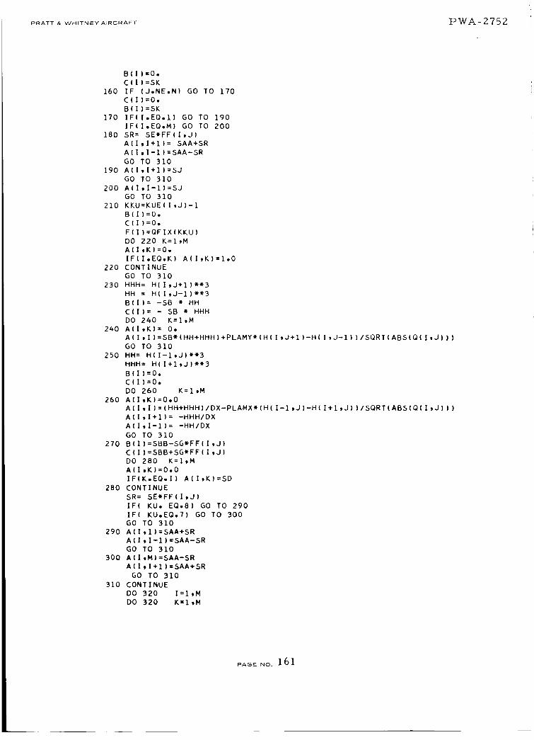
PRATT&WHITNEYA_RCRAFT "1D"r_A- Z"7 5 Z
B(I)=0.
C(I)=SK
160 IF (J,NE,N) GO TO 170
C(1)=0.
B(I)=SK
170 IF{I.EQ,1) GO TO 190
IF(I,EQ,M) GO TO 200
180 SR= SE*FF(I,J)
A(IoI+l)= SAA+SR
A(I_I-1)=SAA-SR
GO TO 310
190 A(I,I+I)=SJ
GO TO 310
200 A(I_I-1)=SJ
GO TO 310
210 KKU=KUE(I,J)-I
B(1)=0,
C(1)=O,
F(1)=QFIX(KKU)
DO 220 K=I,M
A(ItK)=0,
IF(I,EQ,K) A(I,K}=I,0
220 CONTINUE
GO TO 310
230 HHH= H(I,J+I)_*3
HH = H(ItJ-l)_3
B(1): -SB * HH
C(1)= - SB * HHH
DO 240 K=ltM
240 A(I,K)= 0.
A(Itl)=SB_(HH+HHHI+PLAMY*(H(ItJ+I)-H(I,J-I))/SQRT(ABS(Q(ItJ)))
GO TO 310
250 HH= H(I-1,J)**3
HHH= H(I+I*J)_*3
B(1)=0.
CII)=0.
DO 260 K=ltM
260 A(ItK)=O,O
A(Itl)=(HH+HHH)/DX-PLAMX*(H(I-1,J)-H(I+ItJ))ISQRT(ABS(Q(ItJ)))
A(I,I+I)= -HHH/DX
A(I,I-1)= -HH/DX
GO TO 310
270 B(1)=SBB-SG_FF(I,J)
C(I)=SBB+SG_FF(I,J)
DO 280 K=ItM
A(I,K)=0o0
IF(K.EQ,I) A(I,K)=SD
280 CONTINUE
SR= SE*FF(I_J)
IF( KU. EQ,8) GO TO 290
IF( KU,EQ,7) GO TO 300
GO TO 310
290 A(I,I)=SAA+SR
A(I_I-I)=SAA-SR
GO TO 310
300 A(I,MI=SAA-SR
A(191+I)=SAA+SR
GO TO 310
310 CONTINUE
DO 320 I=IgM
DO 320 K=I,M
PAGE NO. 161

PRATT & WHITNEY AIRCRAFT t:) W.A.- Z'7 5
320 QSMA(IoK):A(IJK) + B(1)*E(ItK,J)
CALL MAIINV(QSMA,M,BB,O,DET,ID)
GO TO (340,330)tiD
340 DO 360 I=I,M
GlltJ+l}=O.
DO 360 K=IoM
GII,J+I)=GIItJ+II+QSMA(I_KI*(F(KI-B{KI*GIKoJ))
E(I,K,J+II=-QSMA(I,KImC(K}
IFI,NOT.JOINT) GO TO 360
DUN=Q.O
DO 350 KK=I,M
350 DUM=DUM-QSMAiI,KKI*B(KK)mD(KK,KtJ)
D(I,K,J+II=DUM
360 CONTINUE
370 CONTINUE
DMA=O,O
IFIJOINT) GO TO 410
DO 380 I=ltM
DMA=AMAXI(DMAtABS(Q(ItN)-G(19N+I)))
380 QII,N)=G(ItN+I)
DO 400 JJ=2tN
J=N+2-JJ
DO 400 I=ItM
DUM=O,O
DO 390 K=ltM
390 DUM=DUM+E(I,KoJ}_Q(K_J)
DUM=DUM+G(I,J)
DMA=AMAXI(DMA,ABS(DUM-Q(ItJ-1))!
400 Q(ItJ-1)=DUM
GO TO 560
410 DO 420 1 = ltM
DO 420 K=I,M
QSNA(I,K) = -DII_KtN+I)
IF(IoEQ,K)QSMA(IoK)=QSMA(I_K)+I,0
420 CONTINUE
CALL MATINV(QSMA,MoBBtOtDET,ID)
GO TO (430,330)tID
330 WRITE(NW,3) J
GO TO 10
430 DO 460 I=ltM
DU= 0.0
DO 450 K=I,M
DUM= 0.0
DO 440 KK=I_M
440 DUM=DUM+QSMA(I,KK)_E(KK,K iN+l)
R(ItK_N)=DUM
450 DU=DU+QSMA(I,K)tG(K,N+I)
460 S(I,N)=DU
DO 490 JJ=2tN
J= N+2-JJ
DO 490 I=ltN
DU=0,0
DO 480 K=I,M
DUM=O,O
DO 470 KK=ItM
470 DUN- D(I,KKtJ)*R(KKtK_N)+EiltKKoJ)mR(KKgK_J)+DUM
R(ItKtJ-li=DUM
480 DU=DU+D(I,KgJ)eSIKtN)+E(ItKtJ)iS(KgJ)
490 S(I_J-1I=DU+G(IgJ)
DMA=OoO
DO 500 I=I_M
PAGE NO. 16Z

PRATT & WHITNEY AIRCRAFT "ICI'W'A - _.'75 g
DO 500 K=I,M
QSMA(I,K)=-R(I,Kgl)
IF(I,EQ.K)QSMAII_K)= QSMA(I,K)+I.O
500 CONTINUE
CALL MATINV(QSMA_M,BB,O,DET,ID)
GO TO(51Ot330),ID
510 DO 530 I:I,M
DU:O.O
DO 520 K=I,M
520 DU=DU+QSMAIItK)_S(Ktl)
DMA=AMAXl(DMA,ABS(DU-Q(I,I)))
530 O(I,1)=DU
DO 550 J=2,N
DO 550 I=I,M
DU=O.O
DO 540 K=I_M
540 DU:DU+R(I,K,J)*Q(K,I)
DU:DU+S(I,J)
DMA: AMAXI(DMA_ABS(DU-Q(I,J)))
550 Q(ItJ)=DU
560 IF(QREP) WRITE(NW,4JQ
KOUNT=KOUNT+I
IF(KOUNT.GE.LKOUNT)GO TO 561
IF(DMA .GT. 10.0_*FLOAT(-NDIG)
561 WRITE(NW,5)NDIG,KOUNT
WRITE(NW,I1)
IF(PPOUT)WRITE(NW,9)
DO 575 I=I,M
IF(PPOUT)WRITE(NWo4)(Q(I,J),J:I,N)
DO 570 J=IgN
570 Q(I,J):SQRT(ABS(O(I,J)))
575 CONTINUE
IF(POUT)WRITE(NW,8)
DO 576 I=I,M
IF(POUT)WRITEINW,4)IQ (I,J),J=I,N)
576 CONTINUE
DO 590 I=I,M
X= DX*FLOAT(I-I)
DO 580 J=I,N
580 QQQ(J)=Q(I,J)
PP(I) = SUM(OQOtN_DY)
590 PX(I) = PP(1)_X
DO 610 J=I,N
Y= FLOAT( J-1)*DY
DO 600 I=I,M
600 QQQ(1)= Q(ItJ)
610 PY(J)=SUM(QOQ_MtDX)_Y
FP= SUM(PPtM,DX)
FX= SUM(PX,M,DX)
XF =FX/FP
Fy= SUM(PY,N,DY)
YF=FY/FP/YOX
FP=FP/YOX
WRITE(NW,6) NCASEtFPgXF,YF
DO 620 I=I_M
620 PPII)=QII,JFLO)*HII,JFLO)*I-PLAMY+HII,JFLO)_*2
I*(Q(ItJFLO+II-Q(IgJFLO-I))/(2.*DY))
FLOY=SUM(PP,M_DX)
DO 690 J=I,N
630 PP(J)=Q(IFLO,J)*H(IFLO,J)*(-PLAMX+H(IFLO,J)**2
I*(Q(IFLO+I,J)-Q(IFLO-1,J))/(2.*DX))
FLox=suM(PPtNtDYI/YOX
WRITE(NW,7) FLOX,FLOY
GO TO 10
END
)GO TO I00
PAGE No. I63

PRATT & WHITNEY A#RCRAFT PWA-2752
FORTRAN DECKPLSTOU
Tlr_nr !BMFA,1_vv_
FUNCTION SUM(PtMtDX!
DIMENSION P(33)
K=2
KK=M-1
KKK=2
SUM=0,O
10 DO 20 I=KtKKtKKK
20 SUM=SUM+P(I)
GO TO (30*40tS0)tK
30 SUM=SUM*DX/3.0
RETURN
45 SUM=2,0tSUM
GO TO 10
50 K=I
KK=M
KKK=M-1
GO TO 45
END
PAGE No. 164
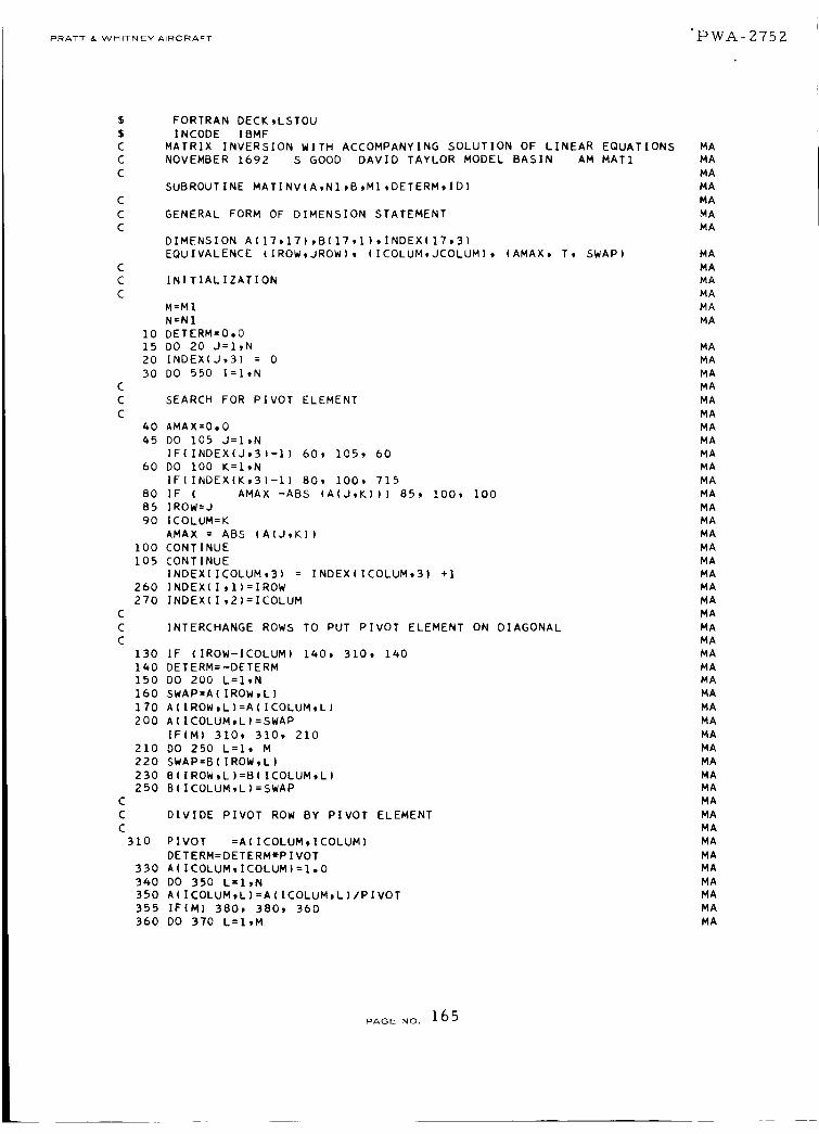
PRATT & WHITNEY AIRCRAFT "PWA- 2752
C
C
C
FORTRAN DECK,LSTOU
INCODE IBMF
MATRIX INVERSION WITH ACCOMPANYING SOLUTION OF LINEAR EQUATIONS
NOVEMBER 1692 S GOOD DAVID TAYLOR MODEL BASIN AM MAT1
SUBROUTINE MATINVIA,NI,B,MI,DETERM,ID)
GENERAL FORM OF DIMENSION STATEMENT
DIMENSION A(17,1?i,B(1?,l},INDEXI17,3)
EQUIVALENCE (IROW,JROW), (ICOLUM,JCOLUM}, (AMAX, T, SWAP}
INITIALIZATION
M=M1
N=NI
10 DETERM=O,O
15 DO 20 J=I,N
20 INDEX(J,3} = 0
30 DO 550 I=I,N
SEARCH FOR PIVOT ELEMENT
40 AMAX=O,O
45 DO 105 J=I,N
IFIINDEX(J,3)-I) 60, 105, 60
60 DO 100 K=I,N
IFIINDEXIK,3)-I) 80, 100, 715
80 IF ( AMAX -ABS (A(J,K))) 85, 100, 100
85 IROW=J
90 ICOLUM=K
AMAX = ABS (A(J,K))
IO0 CONTINUE
105 CONTINUE
INDEX(ICOLUM,3) = INDEX(ICOLUM,3) +1
260 INDEX(I,1)=IROW
270 INDEX(I,2)=ICOLUM
INTERCHANGE ROWS TO PUT PIVOT ELEMENT ON DIAGONAL
130 IF (IROW-ICOLUM) 140, 310, 140
140 DETERM=-DETERM
150 DO 200 L=I,N
160 SWAP=A(IROW,L)
170 A(IROW,L)=A(ICOLUM,L)
200 AIICOLUM,L)=SWAP
IF(M} 310, 310, 210
210 DO 250 L=I, M
220 SWAP=B(IROW,L}
230 B(IROW,L)=B(ICOLUM,L}
250 B(ICOLUM,L)=SWAP
DIVIDE PIVOT ROW BY PIVOT ELEMENT
310 PIVOT :AIICOLUMtICOLUM)
DETERM:DETERM*PIVOT
330 A(ICOLUM,ICOLUM):I,0
340 DO 350 L=I,N
350 AIICOLUM,LI=AIICOLUM,L)/PIVOT
355 IFIM) 380, 380, 360
360 DO 370 L=I,M
MA
MA
MA
MA
MA
MA
MA
MA
MA
MA
MA
MA
MA
MA
MA
MA
MA
MA
MA
MA
MA
MA
MA
MA
MA
MA
MA
MA
MA
MA
MA
MA
MA
MA
MA
MA
MA
MA
MA
MA
MA
MA
MA
MA
MA
MA
MA
MA
MA
MA
MA
MA
MA
MA
MA
MA
MA
PAGE NO. 165

PRATT & WHITNEY AIRCRAFT PWA- 2752
C
C
C
370 BIICOLUMtLI=B(ICOLUMoLIIPIVOT
REDUCE NON-PIVOT ROWS
380 DO 550 LI=IIN
390 IFiLI-ICOLUM) 400_ 550, 400
400 T=A|LltICOLUM)
420 A|LItICOLUM)=O.O
430 DO 450 L=I,N
450 A(L19L)=A(LItL)-A(ICOLUMgL)_T
455 IF(M) 5509 5509 460
460 DO 500 L=ltM
500 B|LltL}=B(L19L}-B(ICOLUMgL)m T
550 CONTINUE
INTERCHANGE COLUMNS
600 DO 710 I=ltN
610 L=N+I-I
620 IF (INDEX(Ltl}-INDEX(L,2)} 6309
630 JROW=INDEX(L91}
640 JCOLUM=INDEX(L92)
650 DO 705 K=lgN660 SWAP=AIKeJROw)
670 AIKgJROW}=A(KtJCOLUM)
700 A(KeJCOLUM)=SWAP
705 CONTINUE
710 CONTINUE
DO 730 K = 19N
IFIINDEX(K93} -1} 71597209715
715 ID =2
GO TO 7_0
720 CONTINUE
730 CONTINUE
ID=I
740 RETURN
LAST CARD OF PROGRAM
END
7109 630
MA
MA
MA
MA
MA
MA
MA
MA
MA
MA
MA
MA
MA
MA
MA
MA
MA
MA
MA
MA
MA
MA
MA
MA
MA
MA
MA
MA
MA
MA
MA
MA
MA
MA
MA
MA
PA6E No. 166
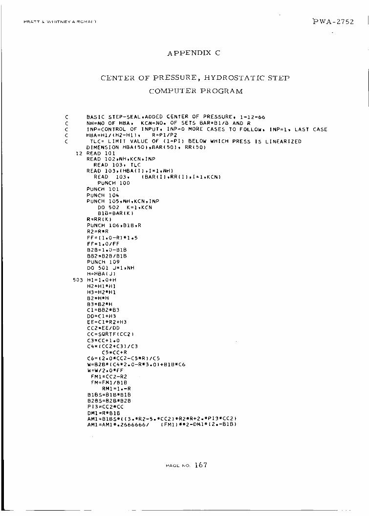
PRATT & WHITNEY AIRCRAFT _P WA - 2'7 5 2_,
A PPENDIX C
CENTER OF PRESSURE, HYDROSTATIC STEP
COMPUTER PROGRAM
12
503
BASIC STEP-SEAL,ADDED CENTER OF PRESSURE, 1-12-66
NH:NO OF HBA, KCN:NO. OF SETS BAR:BI/B AND R
INP:CONTROL OF INPUT, INP:O MORE CASES TO FOLLOW, INP:I, LAST CASE
HBA:HIIIH2-HI), R=PI/P2
TLC= LIMIT VALUE OF (1-Pl) BELOW WHICH PRESS IS LINEARIZED
DIMENSION HBAI50),BAR(50), RR(50)
READ 101
READ 102,NH,KCN,INP
READ 103, TLC
READ 103,(HBA(1),I:I,NH)
READ 103, {BAR(1),RR(1),I=I,KCN)
PUNCH i00
PUNCH 101
PUNCH 104
PUNCH I05,NH,KCN,INP
DO 502 K=I,KCN
BIB:BARIK)
R:RR(K)
PUNCH 106,BIB,R
R2:R*R
FF:II.0-R)*I,5
FF=I.O/FF
B2B=I.O-B18
BB2=B2B/BIB
PUNCH 109
DO 501 J=I,NH
H:HBA(J)
HI=I°0+H
H2=HllH1
H3=H2*H1
B2=HtH
B3=B2_H
CI=BB2_B3
DD:CI+H3
EE=CliR2+H3
CC2=EE/DD
CC:SQRTF(CC2)
C3:CC+l°0
C4=(CC2+C3)/C3
CS=CC+R
C6=(2°0_£C2-C5-R)/C5
W=B2Bt(C4_2,0-R_3°O)+BIB_C6
W=W/2,0_FF
FMI=CC2-R2
FM:FMI/BIB
RMI:Io-R
BIBS=BIB*BIB
B2BS=B2B*B2B
PI3=CC2*CC
DMI=R*BIB
AMI=BIBS*((3.*R2-5.*CC2)*R2*R+2.*PI3*CC2)
AM1=AM1*.2666666/ (FMI)_2-DMI*(2°-BIB)
PAGE NO. 167

PRATT & WHITNEY AIRCRAFTPWA-2752
1 +I-333333_BIB*B2B_(CC2+R_C5 )IC5AMI=AMI/RMI
DIFC=I.-CC
IF (DIFC-TLC) 30,30, 3430 AM2=B2BS-DIFCWFF
GO TO 36
34 AM2=(13.*CC2-5.)_PI3+2.It.26666661(lo_CC2)_w2AM2=(AM2-RItB2BS/RMI
36 XBAR=(AMI+AM2)/W*.5
CI=BB2_B2
DRH=(ClmR2+H2I_DD-(CI+H2I_EE
DRH=DRHIDD*I.SIDDICC
C1=C3_C3
C2=C5tC5
CT=(CC2+2,0*CC}/Cl_B2B
WR=(CC2+2.0_CC_R)/C2_B1B
WR=(C7+WRIWFF
WH=DRH*WR
IF(SENSE SWITCH I I 40*k2
40 PUNCH 103*AM1,AM2
42 PUNCH 103*H,W,WH.FM,XBAR,CC
501 CONTINUE
PUNCH 108
502 CONTINUE
201 IF(INP) 202,12,202
202 STOP
100 FORMAT( 31H HYDRO-STATIC, BASIC STEP-SEAL I}
101FORMAT(72HO
1
102
103
105
104
106
108
1091
END
FORMAT(SISI
FORMAT(6(1X1PE11.4)}
FORMATf3XI4e6XI4,6XI4,6XI4,6XI4}
FORMAT(28HONO OF HBAR SETS B-R
FORMAT(THO B1/B=tE13.6,6H
FORMAT(1HII
FORMAT(66H H1/(H2-H1) WBAR
PI )
INP }
R=,E13,61
DW/DHBAR MBAR XBAR
PAGE NO. 168

PRATT & WHITNEY AIRCRAFT lbWA_2752
APPENDIX D
PRESSURE AND FLOW, SPIRAL GROOVE
COMPUTER PROGRAM
PRESSURE AND MASS FLOW RELATIONSHIP, SPIRAL-GROOVED SEAL
INPUT
AMK=LAMBDAWK1 (LAMBDA=COMPRESSIBILITY NUMBER, KI=GROOVE CONSTANT)
F3WW=DIMENSIONAL ARRY OF F3W (F3W=MBAR/LAMBDA)KI
EPS=CONVERGENCE CRITERION OF SOLVING P2/PI IN AN IMPLICIT EQUATION
OF P2/Pl AND MBAR FOR A GIVEN MBAR
NRUN=NO, OF CASES TO BE CALCULATED* NF3W= NO. OF F3W TO BE CALCUL.
OUTPUT
AMK,K3W (K3W=F3W_K2/Klt K2=GROOVE CONSTANT}, P2/Pl, MBAR
MBAR=DIMENSIONLESS FLOW
DIMENSION F3WW(60}
READ 2, EPS
READ 1,NRUN
PUNCH 3
DO 32 NR=I,NRUN
READ 4,NF3WtAMK
READ 2,(F3WW(N),N=I*NF3W)
DO 32 K=I*NF3W
F3w=F3WW(K)/AMK
I=1
P=AMK*(I.0-F3W)+I.0
10 TEMP=(P-F3W)/(1.-F3W)
IF(TEMP)35,11,11
11 FE=AMK-(P-I.0)-F3WmLOGF(TEMP)
DFE= -1.0-F3W/(P -F3W)
DP= -FE/DFE
ADP= ABSF(DP/P)
IFiADP-EPS) 30,30,20
20 IF(I-50)22,36,36
22 I=I+l
IF(SENSE SWITCH i) 25,26
25 PUNCH 2,P,OP,FE,DFE
26 P=P+DP
GO TO iO
30 PUNCH 2,AMK,F3w,P ,F3WW(K)
GO TO 32
35 PUNCH 5,TEMP
PUNCH 3
GO TO 30
36 PUNCH 6,I
PUNCH 3
GO TO 30
32 CONTINUE
31 STOP
1 FORMAT(1H ,1515)
2 FORMAT(IH ,6E12.5)
3 FORMAT(BH KILAMDA 5X 3HK3W 9X 5HP2/Pl 7X 4HMBAR)
4 FORMAT(15. E12.5)
5 FORMATI34H NEGATIVE LOG (P-F3W)/(I.-F3W)= tEl2.5)
6 FORMAT(ISH DIVERGE I= .15)
END
PAGE NO. 169

PRATT & WHITNEY AIRCRAFTPWA- 2752
BIBLIOGRAPHY
Eckert, E.R. and Robert M. Drake, Jr., "Heat and Mass Transfer,"
McGraw-Hill Book Co., New York, 1959
Fuller, Dudley D., "Theory and Practice of Lubrication for Engineers,"
John Wiley & Sons, Inc., New York, 1956
Grassam, N.S. and J.W. Powell, "Gas Lubricated Bearings, " Butter-
worth, Inc., London, 1964
Jakob, Max and George Hawkins, "Elements of Heat Transfer," third
edition, John Wiley & Sons, Inc., New York, 1958
Lave, J.H., "Hydrostatic Gas Bearings, " California Institute of
Technology Progress Report No. 20-353 Pasadena, 1958
McAdams, William H., "Heat Transmission," McGraw-Hill Book Co.,New York, 1942
Pinkus, Oscar and Beno Sternlicht, "Theory of Hydrodynamic
Lubrication," McGraw-Hill Book Co., New York, 1961
Shapiro, A.H., "The Dynamics and Thermodynamics of CompressibleFluid Flow, Vol. l" The Ronald Press Co., New York, 1953
Wildman, M., "Grooved Plate Gas Lubricated Thrust Bearings, with
Special References to the Spiral Groove Bearing, " Ampex Corporation,
Prepared under Contract No. NoNR-3815(00), Fluid Dynamics Branch,
ONR, RR 64-i, Jan. 1964
Keenan, J.H. and J. Kaye, "Gas Tables", John Wiley & Sons, NewYork 1961
Schlichting, H., "Boundary Layer Theory, " Fourth Edition, McGraw-
Hill, New York, 1960
Arwas, E.B. and Sternlicht, B., "Viscous Shear Compressor,"
Mechanical Technology Incorporated, Technical Report MTI 62TR21
Lund, J.W., "Gas Bearing Design Methods Vol. 2," Mechanical
Technology Incorporated Technical Report, MTI 65TR5-II
Cheng, H.S., Chow, C.Y., and Murray S.F., "Gas Bearing Design
Methods Vol. I", Mechanical Technology Incorporated Technical
Report, MTI 65TR5-II
Tang, I.C., and Gross, W.A., "Analysis and Design of Externally
Pressurized Gas Bearings", ASLE Trans. 5, 261-285 (1962)
PAGE NO. 1 70

PRATT & WHITNEYAIRCRAFT
PWA- 27,52
REFERENCES
o
°
.
.
°
.
Arwas, E.B., and B. Sternlicht, "Viscous Shear Compressor,"
MTI-62TR21, (September, 1962).
Timoshenko, S., Strength of Materials, Part II, D. Van
Nostrand Co., Inc. Third Edition, 1956.
Hsing, F. and T. Chiang, "Discharge Coefficient of Orifices and
Nozzles, " Mechanical Technology Inc. Technical MemoMTI-65TM7.
Castelli, V. and J. Pirvics, "Equilibrium Characteristics of
Axial-Groove Gas-Lubricated Bearings, " ASME 65-LUB-
(1965).
Arwas, E.B. and Sternlicht, B., "Viscous Shear Compressor",
Mechanical Technology Incorporated, Technical ReportMTI-62TR21.
Lund, J.W., "Gas Bearing Design Methods Vol. 2", Mechanical
Technology Incorporated Technical Report, MTI-65TR5-II.
. Cheng, H.S., Chow, C.Y., and Murray, S.F., "Gas Bearing
Design Methods Vol. I", Mechanical Technology Incorpo-
rated Technical Report, MTI-65TR5-II.
8. Tang, I.C., and Gross, W.A., "Analysis and Design of Ex-
ternally Pressurized Gas Bearings", ASLE Trans. 5,
?.61-285 (1962).
Appendix B
9. Castelli, V. and J. Pirvics. "Equilibrium Characteristics of
Axial-Groove Gas-Lubricated Bearings, " ASME 65-LUB-
(1965).
PAGE NO. 1 7 1

PRATT & WHITNEY AIRCRAFT PWA-Z75Z
Semiannual Reports Distribution List
NAS 3-7605
Addressee
I. NASA-Lewis Research Center
Spacecraft Technology
Procurement Section
Attention: John H. DeFord
Z. NASA-Lewis Research Center
Spacecraft Technology Divxslon
Attention: J. Howard Childs
W. H, Roudebush
D.P. Townsend (3)
3. NASA-Lewis Research Center
Technical Utilization Office
Attention: John Weber
4. NASA-Le_vis Research Center
Reports Control Office
5. NASA-Lewis Research Center
Attention: Library
6. NASA-Scientific and Technical Information Facility(G)
Box 5700
Bethesda, Ma ryland
Attention: NASA Representative
7. NASA-Lewis Research Center
Fluid System Components Division
Attention: I. I. Pinkel
E. E, Disson
R. L. Johnson
W. R. Loomis
L. P. Ludwig
N. A. Swikert
T. B. Shillito
H. J. Ha rtmann
8. Air Force Materials Laboratory
Wright-Patterson Air Force Base, Ohio
Attention: MANL, R. Adamczak
MANE, R. Headrick and J. N. Keible
MAAE, P. House
9. Air Force Systems Engineering Group
Wright-Patterson Air Force Bases Ohio
Attention: SESMS, J. L. Wilkins
SEJPF, S. Prete
t0. Air Force Aero Propulsion Laboratory
Wright-Patterson Air Force Base, Ohio
Attention: AFAPL (APFL), K. ]-. Berkey & L.
De B rahum
AFAPL (APTC), C. Simpson
APTP, I. J. C, ershon
11. FAA Headquarters
800 Independence Avenue, S. W.
Washington, D.C.
Attention: J. Chavkin SS/120
M. Lott FS/141
1Z. NASA Headquarters
Washington, D.C. Z0546
Attention: N. F. Rekos (RAP)
A. J. Evans (RAD)
J. Maltz (RRM)
13. NASA-Langley Research Center
Langley Station
Hampton, Virginia 23365
Attenti_on: Mark R. Nichols
14. Mechanical Technology, Incorporated
968 Albany-Shaker Road
Latham, New York
Attention: D. Wilcock
15. Clevite Corporation
Cleveland Graphite Bronze Division
17000 St. Clair Avenue
Cleveland, Ohio 44110
Attention: T. H. Koenig
16. Koppers Company, Incorporated
Metal Products Division
Piston Ring and Seal Department
Baltimore 3, Maryland
Attention: T. C. Kuchler
17. Stein Seal Company
Z0th Street and Indiana Avenue
Philadelphis 3Z, Pennsylvania
Attention: Dr. P. C. Stein
18. Wright Aeronautical Division
Curtiss-W right Corporation
333 West 1st Street
Dayton 2, Ohio
Attention: S. Lombardo
19. TRW, Incorporated
23555 Euclid Avenue
Cleveland, Ohio 44117
Attention: O. Decker
Z0. General Electric Company
Advanced Engine and Technology Department
Cincinnati, Ohio 45Z 15
Attention: L. B. Venable
G. J. Wile
Zl. Huyck Metals Company
P.O. Box 30
45 Woodmont Road
k{ilfo rd, Connecticut
Attention: J. L Fisher
Z2. Ae rojet-Gcneral Corporation
20545 Center Ridge Road
Cleveland, Ohio 44116
Attention: W. L. Snapp
Z3. Lycoming Division
Avco Corporation
Stratford, Connecticut
Attention: R. Cuny
24. Battelle Memorial Institute
505 King Avenue
Columbus I, Ohio
Attention: C.M. Allen
Z5. Bendix Corporation
Fisher Building
Detroit 2, Michigan
Attention: R. H. !saccs
26. Boeing Aircraft Company
2Z4 N. Wilkinson
Dayton, Ohio 45402
Attention: H. W. Walker
PAG_NO.172
PRATT & WHITNEYAIRCRAFT PWA-Z752
Addressee
27. Douglas Aircraft Company
Holiday Office Center
16501 Brookpark Road
Cleveland_ Ohio 44135
Attention: J. J. Pakiz
?-8. General Dynamics Corporation
16501 Brookpark Road
Cleveland, Ohio 44135
Attention: George Vila
29. General Motors Corporatiun
Allison Division
Plant #8
Indianapolis, Indiana
Attention: E. H. Deckman
30. Lockhead Aircraft Compan}
16501 Brookpark Road
Cleveland, Ohio 44 135
Attention: Mr. k. Kelly
31. Martin Company
16501 Brookpark Road
Cleveland, Ohio 44 135
Attention: Z. G. Horvath
3Z. North American Aviation
16501 Brookpark Road
Cleveland, Ohio 44135
Attention: George Brcmer
33. Fa irchild-Itiile r Corporation
Republic Aviation Division
Farmingdatc, Long Island
Ne_ York 11735
Attention: D. Schroeder
34. Westinghouse Electric Corporation
55 Public Square
Cleveland, Ohio 44113
Attention: Lynn Powers
35. I.I.T. Research Foundation
10 West 35 Street
Chicago, Illinois 60616
Attention: Dr. Strohmelcr
36. Pesco Products Division
Borg-Warner Corporation
24700 N. Niles
Bedford, Ohio
37. Stanford Research Institute
Menlo Park, California
Attention: R. C. Key
38. Franklin Institute Laboratories
20th and Parkway
Philadelphia 3, Pennsylvania
Attention: J. V. Carlson
39. Industrial Tectonics
Box 401
Hicksville, New York ll801
Attention: J. Cherubin
40. Seal01 Incorporated
P.O. Box 2158
Providence 5, Rhode Island
Attention: Justus Stevens
41. Continental Aviation and Engineering
IZ700 Ke rcheval
Detroit 15, Michigan
Attention: A. J. Yallman
4Z. Northrop Corporation
1730 K. Street, N.W.
Suite 903-5
Washington 6, D.C.
Attention: S. W. Fowler, Jr.
43. Chicago Rawhide Manufacturing Company
1311 Elston Avenue
Chicago, Illinois
Attention: R. Blair
44. Midwest Research Institute
4Z5 Volker Blvd.
Kansas City 10, Missouri
Attention: V. Hopkins
45. Southwest Research Institute
San Antonio, Texas
Attention: P. M. Ku
46. E.I. DuPont de Nemours and Company
I007 Market Street
Wilrnington 98, Delaware
Attention: A. J. Cheney
R. J. Laux
47. Fairchild Engine and Airplane Corporation
St ratos Division
Bay Shore, New York
48. Borg-Warner Corporation
Roy C. Ingersoll Research Center
Wolf and Algonquin Roads
Des Plaines, Illinois
49. U.S. Naval Air Material Center
Aeronautical Engine Laboratory
Philadelphia 12, Pennsylvania
Attention: A. L. Lockwood
50. Department of the Navy
Bureau of Naval Weapons
Washington, D.C.
Attention: A. B. Nehman, RAAE-3
C. C. Singleterry, RAPP-4
51. Department of the Navy
Bureau of Ships
Washington 75, D.C.
Attention: Harry King, Code 634-A
5Z. SKF Industries, Incorporated
If00 First Avenue
King of Prussia, Pennsylvania
Attention: L. B. Slbley
53. Crane Packing Company
6400 W. Oakton Street
Norton Groove, Illinois
Attention: Harry Tankus
54. B. F. Goodrich Company
Ae rospace and Defense Products Division
Troy, Ohio
Attention: L. S. Blaikowski
PAGE NO. 173

PRATT & WHITNEY AIRCRAFT PW.A -_- 75Z
Addressee
55.
56.
57.
58.
59.
60,
61.
62.
63.
64.
65.
66.
67.
The University of Tennessee
Department of Mechanical and Aerospace
E ngioe e ring
K noxville, Tennessee
Attention: Professor W. K. Stair
Hughes Aircraft Company
International Airport Station
P.O. Boxg0515
Los Angeles 9, California
U. S. Navy Marine Engineering Lab.Friction and Wear Division
Annapolis, Maryland
Attention: R. B. Snapp
Metal Bellows Corporation
20977 Knapp StreetChatsworth, California
Attention: Sal Artino
Rocketdyne
6633 Canoga Avenue
Canoga Park, California
Attention: M. Butner
Carbon Products Division of Union Carbide
Corporation
270 Park Avenue
New York 17, New York
Attention: $o Curean
Garlock, Incorporated
Palmyra, New York 14522
Attention: 1_. W. Fisher
Chenl_cals Division of Union Carbide Corp.
Technical Service Lab.
P.O. Box 65
Tarryto_vn, New York
Attention: J. C. Haaga
Durametallic Corporation
Kalamazoo, Michigan
Attention: H. Hummer
Morganite, Incorporated33-02 48th Avenue
L.I.C. 1, New York
Attention: S. A. Rokaw
United States Graphite Company
1621 Holland
Saginaw, MichiganAttention: F. F. Ruhl
Cartiseal Corporation
3515 West Touhy
Lincolnwood, nlinois
Attention: R. Voitik
Department of the Army
U. S. Army Aviation Material Laboratory
Fort Eustis, Virginia 23604
Attention: JohnW. White, Chief
p ropuls ion Divis ion
pA6E NO. 174