pre-workshop bulletin of lecture notesccri.in/pdf/carbon_capture_and_storage.pdf · 2013-03-21 ·...
TRANSCRIPT

Awareness and Capacity Building in Carbon Capture and Storage: Earth Processes ACBCCS
2 0 1 3 15th -19th January, 2013, New Delhi
Pre-Workshop Bulletin of Lecture Notes
Supported by
Ministry of Earth SciencesGovernment of India
Workshop Highlights
• CCS Status & Overview - 2 Sessions
• CO2 Reduction in Power Sector - 3 Sessions
• Earth Processes in CO2 Storage & Recycling - 4 Sessions
• CO2 in Industry - 4 Sessions
• Panel Discussion

Organized by
Climate Change Research InstituteNew Delhi
CCRI
Awareness and Capacity Building in Carbon
Capture and Storage: Earth Processes
ACBCCS-2013
IIC Convention Center, January 15-19, 2013
Workshop Highlights
• CCS Status & Overview - 2 Session • CO2 Reduction in Power Sector - 3 Sessions • Earth Processes in CO2 Storage & Recycling - 4 Sessions • CO2 in Industry - 4 Sessions • Panel Discussion
Convener Dr. (Mrs.) Malti Goel
CSIR Emeritus Scientist, Jawaharlal Nehru University, New Delhi & former Adviser and Scientist ‘G’, Department of Science & Technology, New Delhi


R.V. SHChairmaFormer
I Carbon January
InUSA, anIndia, aninteractielaboratand Stoamong India forroad maconcern
In
recently publisheTherefororganizechalleng
I
delibera
________
AHI an, EnergyPower Se
am pleaseCapture an
y 15-19, 201
ndia being n initiative nd Global on is organted for brorage (CCSindustry. It r a possibleap on the ed agencie
nternationaa new scie
ers like Elsre I apprece a capacge.
wish the wtions.
__________
1st FlooTe
y Infratechcretary, G
ed to know nd Storage:13.
the foundewith whichCarbon Ca
nised to enhadening th) under Clehas becom
e change iresearch n
es.
lly researchentific ‘Joursevier. Indiciate this inity building
workshop a
___________or, NBCC Towel: 011‐46598Email : rvsh
h ovt. of Ind
Foreword
that a wor: Earth Proc
er memberh I was cloapture and hance undee perspect
ean Develome necessn its socialneeds in C
h has beenrnal of CO2a is amonnitiative to g workshop
great succe
__________wer, 15 Bhik8888 (D), [email protected];
dia
rkshop on ‘Acesses’ is p
r of Carboosely assoc
Storage Inerstanding otives on CCpment Mecary to revie acceptanc
CCS and s
n growing e2 Utilizationng major c
synergize p. Industry
ess and loo
___________kaiji Cama P6519700 (B),rvshahi@en
Awarenessplanned to
on Sequestciated as Snstitute, Auon CO2 recCS. Accepchanism haew the CCce. It is alssubmit the
exponentialn’ has beencoal based
the researhas to co
ok forward
__________Place, New D, Fax : 011 –nergyinfrate
s and Capabe held in
tration LeadSecretary Pstralia, it is
cycling. Issptance of Cas aroused CS scenarioso necessa
recommen
lly and I amn launched
economiesrch efforts ome forwa
to good ou
(R. V. Sh___________Delhi – 110 046529746 ech.com
acity BuildinNew Delhi
dership FoPower, Govs timely thasues need tCarbon Cap
special inteo, particularry to develndations to
m told that by internats in the win India an
ard to take
utcome from
ahi) __________066
ng in from
orum, vt. of at an to be pture erest rly in lop a o the
very tional world. nd to e the
m the
_____

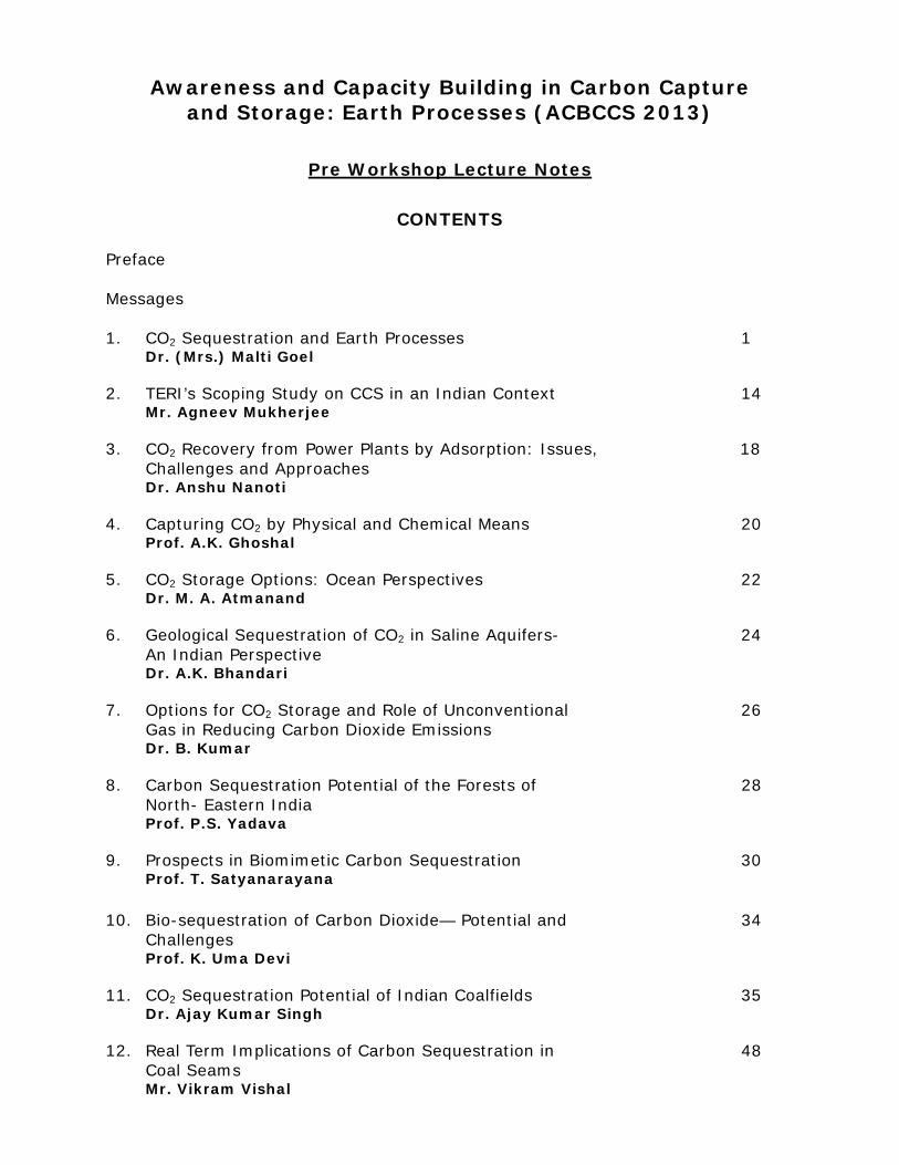
Awareness and Capacity Building in Carbon Capture and Storage: Earth Processes (ACBCCS 2013)
Pre Workshop Lecture Notes
CONTENTS
Preface Messages 1. CO2 Sequestration and Earth Processes 1
Dr. (Mrs.) Malti Goel 2. TERI’s Scoping Study on CCS in an Indian Context 14
Mr. Agneev Mukherjee 3. CO2 Recovery from Power Plants by Adsorption: Issues, 18
Challenges and Approaches Dr. Anshu Nanoti
4. Capturing CO2 by Physical and Chemical Means 20 Prof. A.K. Ghoshal
5. CO2 Storage Options: Ocean Perspectives 22
Dr. M. A. Atmanand
6. Geological Sequestration of CO2 in Saline Aquifers- 24 An Indian Perspective Dr. A.K. Bhandari
7. Options for CO2 Storage and Role of Unconventional 26
Gas in Reducing Carbon Dioxide Emissions Dr. B. Kumar
8. Carbon Sequestration Potential of the Forests of 28
North- Eastern India Prof. P.S. Yadava
9. Prospects in Biomimetic Carbon Sequestration 30
Prof. T. Satyanarayana 10. Bio-sequestration of Carbon Dioxide— Potential and 34
Challenges Prof. K. Uma Devi
11. CO2 Sequestration Potential of Indian Coalfields 35
Dr. Ajay Kumar Singh 12. Real Term Implications of Carbon Sequestration in 48
Coal Seams Mr. Vikram Vishal

13. Carbon Dioxide Storage and Enhanced Oil Recovery 51
Mr. Gautam Sen 14. CO2 Capture & Sequestration Project 64
Dr. V.K. Sethi

Pre-Workshop Bulletin of Lecture Notes
Awareness and Capacity Building in Carbon Capture and Storage: Earth Processes (ACBCCS-2013), January 15-19, 2013
PREFACE
India’s energy is majorly dependent on ‘King Coal’. The coal combustion also causes the highest CO2 emissions of all fossil fuels. With the growing concerns for climate change threats in the 21st century there has been increasing interest in carbon sequestration technology as insurance for continuation of coal use in our energy supply. According to IPCC assessments the carbon dioxide concentrations have increased from pre industrial value of 280ppm to 386 ppm at present and a safe limit of 450 ppm has been set for the year 2050 to save the Planet Earth. To respond the complex dynamics of climate change predictions, both mitigation and adaption approaches are being developed. Capturing of excess carbon dioxide, its utilization and permanent fixation away from the atmosphere are emerging technology worldwide for mitigation. The challenges are immense and need to be addressed by scientific & technological means.
We need to create awareness not only on the research issues of carbon capture,
utilization and storage options, but also the options for clean energy development in a sustainable manner. It is hoped that the five day national level workshop on Awareness and Capacity Building in Carbon Capture and Storage: Earth Processes (ACBCCS‐2013) being held from January 15‐19, 2013, New Delhi will provide a platform for the young researchers to learn more about the about the scientific & technological challenges faced by us in CCS and CCUS in the context of global climate change. .
On this occasion I would like to thank Shri R.V. Shahi, Chairman, National Advisory
Board for his support and encouragement. I feel indebted to overwhelming response from the eminent experts and delegates from various institutions across the country. The support from Ministry of Earth Sciences, Government of India for this capacity building workshop is highly acknowledged.
Dr. (Mrs.) Malti Goel Convener (ACBCCS‐2013)
CSIR Emeritus Scientist & Former Adviser, DST


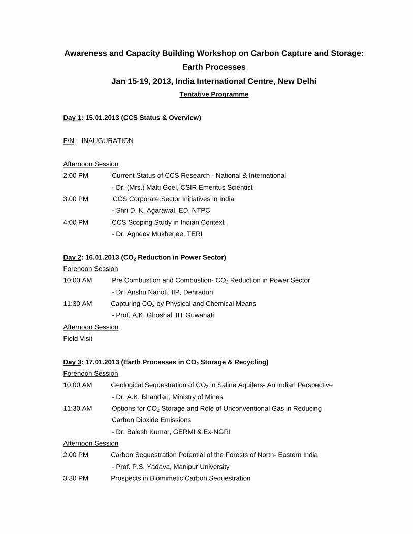
Awareness and Capacity Building Workshop on Carbon Capture and Storage:
Earth Processes
Jan 15-19, 2013, India International Centre, New Delhi
Tentative Programme
Day 1: 15.01.2013 (CCS Status & Overview)
F/N : INAUGURATION
Afternoon Session
2:00 PM Current Status of CCS Research - National & International
- Dr. (Mrs.) Malti Goel, CSIR Emeritus Scientist
3:00 PM CCS Corporate Sector Initiatives in India
- Shri D. K. Agarawal, ED, NTPC
4:00 PM CCS Scoping Study in Indian Context
- Dr. Agneev Mukherjee, TERI
Day 2: 16.01.2013 (CO2 Reduction in Power Sector)
Forenoon Session
10:00 AM Pre Combustion and Combustion- CO2 Reduction in Power Sector
- Dr. Anshu Nanoti, IIP, Dehradun
11:30 AM Capturing CO2 by Physical and Chemical Means
- Prof. A.K. Ghoshal, IIT Guwahati
Afternoon Session
Field Visit
Day 3: 17.01.2013 (Earth Processes in CO2 Storage & Recycling)
Forenoon Session
10:00 AM Geological Sequestration of CO2 in Saline Aquifers- An Indian Perspective
- Dr. A.K. Bhandari, Ministry of Mines
11:30 AM Options for CO2 Storage and Role of Unconventional Gas in Reducing
Carbon Dioxide Emissions
- Dr. Balesh Kumar, GERMI & Ex-NGRI
Afternoon Session
2:00 PM Carbon Sequestration Potential of the Forests of North- Eastern India
- Prof. P.S. Yadava, Manipur University
3:30 PM Prospects in Biomimetic Carbon Sequestration

- Prof. Satyanarayana Tulasi, Delhi University
Bio-sequestration of Carbon Dioxide— Potential and Challenges
- Prof. K. Uma Devi, Anna University
Day 4: 18.01.2013 (CO2 in Industry & Value addition)
Forenoon Session
10:00 AM Opportunity of CO2 Storage in Coal Beds
- Dr. A. K. Singh, CIMFR
11:30 AM Real Term Implications of Carbon Sequestration in Coal Seams
- Mr. Vikram Vishal, IIT Bombay
Afternoon Session
2:00 PM Reservoirs for CO2 Storage & Value Addition – EOR process
- Dr. D.M. Kale, ONGC Energy Centre
3:30 PM Carbon Dioxide Storage and Enhanced Oil Recovery
- Mr. Gautam Sen, Ex- Oil & Gas Consultant, ONGC
Day 5: 19.01.2013 (Panel Discussion and Summing Up)
19th January, 2013
10:00 AM Assembly & Tea
10:30 AM Guest Lecture: Policy and Regulatory Interventions in Abatement of CO2 Footprints
- Shri. V. S. Verma, Member, Central Electricity Regulatory, Commission
11:15 AM Round Table Discussions:
Suggested Topics
- Need for a regulatory / institutional framework in India
- CCS in power and Industry sector
- CCS capacity building needs
- Impact on international development on developing countries
12:00 Concluding Remarks
12:15 Presentation by delegates and Awarding Certificates of Participation
Workshop on Awareness and Capacity Building in Carbon Capture and Storage: Earth Processes (ACBCCS-2013), January 15-19, 2013
Seminar Hall-3, IIC Convention Centre, F.F. (entry from Gate 1), New Delhi – 110003
Programme of Inaugural Session: 10:30 – 12:00 Noon
10:30 hrs. Assembly & Tea
11:00 hrs. Welcome Ms Karishma Vohra, Student TERI
11:05 hrs. Introduction to
Theme
Dr. (Mrs.) Malti Goel, Convener and CSIR
Emeritus Scientist, JNU
11:15 hrs Special Address: Shri M. P. Narayanan, Former Chairman,
Coal India Ltd.
11:35 hrs. Presidential Address: Sh. D.K. Agarwal, Executive Director, NTPC
and Head NTPC-NETRA
11:50 hrs. Inaugural Address: Dr. Harsh K. Gupta, Member, National
Disaster Management Authority and
Former Secretary, DoD
12:00 hrs. Vote of Thanks General Secretary, CCRS
12:05 - 12:35 hrs. Introductory lecture on Carbon Capture and Storage:


CO2 SEQUESTRATION AND EARTH PROCESSES* Dr. (Mrs.) Malti Goel
CSIR Emeritus Scientist, Centre for Studies in Science Policy, Jawaharlal Nehru University, New Delhi-110067, India
Abstract
This paper is dealing with the emerging topic of CO2 Sequestration, which is among
the advanced energy technologies. CO2 Sequestration is being discussed in national
and international forums and is of particular importance to coal based economies.
Various processes for CO2 utilization and recycling in the Earth System are
discussed in detail. Highlights of international large scale projects and current
status in India including future challenges and objectives of ACBCCS-2013 are
presented.
1. Introduction
“The most beautiful experience we can have is the mysterious. It is fundamental emotion, which stands at the cradle of true art and true science.”
- Albert Einstein
Capturing carbon dioxide is an end-of-pipe solution for pollution mitigation in fossil
fuel based energy systems. Significant strides are being made in understanding
carbon capture and storage - CO2 Sequestration in fossil fuel based economies. The
CO2 Sequestration involves capture of excess CO2 from its point sources and its
permanent fixation away from the atmosphere. The various techniques of CO2
capture are derived from gas separation techniques, which include chemical
absorption, membrane separation, physical adsorption, and cryogenic separation at
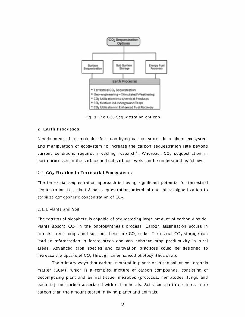
source1. Captured CO2 is then sequestrated by means of surface processes, by sub
surface storage and/or by recovery of energy fuels & minerals (Fig. 1). If the
source and the underground fixation sites are not near to each other, transport of
CO2 in liquid form over longer distances is required. To achieve a carbon balance in
the atmosphere in an enhanced CO2 scenario, science & technology gaps exist in
CO2 capture processes and materials as well as site specific models for its
fixation2,3.
1
2. Earth P
Developme
and manip
current co
earth proce
2.1 CO2 Fi
The terrest
sequestrati
stabilize at
2.1.1 Plant
The terrest
Plants abs
forests, tre
lead to aff
areas. Adv
increase th
The
matter (SO
decomposin
bacteria) a
carbon tha
Processes
ent of techn
ulation of e
nditions re
esses in the
xation in T
trial seques
ion i.e., pla
mospheric c
ts and Soil
trial biosphe
orb CO2 in
ees, crops a
forestation
vanced cro
he uptake of
primary wa
OM), which
ng plant an
nd carbon a
n the amou
Fig. 1 The
nologies for
ecosystem t
quires mod
surface and
Terrestrial
tration app
nt & soil se
concentratio
ere is capab
the photos
and soil and
in forest a
p species
f CO2 throug
ays that car
is a comp
nd animal ti
associated w
nt stored in
CO2 Seque
quantifying
to increase
deling resea
d subsurface
Ecosystem
roach is ha
equestration
on of CO2.
le of seques
synthesis p
d these are
reas and c
and cultiva
gh an enhan
rbon is store
plex mixture
ssue, micro
with soil mi
living plant
estration opt
g carbon st
the carbon
arch4. Wher
e levels can
ms
ving signific
n, microbial
stering large
process. Car
CO2 sinks.
an enhance
ation practi
nced photos
ed in plants
e of carbon
obes (protoz
inerals. Soil
ts and anim
tions
tored in a g
n sequestrat
reas, CO2
n be underst
cant potent
and micro-
e amount o
rbon assim
Terrestrial
e crop prod
ces could
ynthesis rat
or in the so
n compound
zoa, nemat
ls contain t
mals.
given ecosy
tion rate be
sequestratio
tood as follo
tial for terre
-algae fixati
f carbon dio
ilation occu
CO2 storage
ductivity in
be designe
te.
oil as soil or
ds, consisti
todes, fungi
hree times
ystem
eyond
on in
ows:
estrial
on to
oxide.
urs in
e can
rural
ed to
rganic
ng of
, and
more
2
It is estimated that increasing the soil organic carbon (SOC) by 0.01 per
cent could nullify the annual increase in atmospheric carbon due to anthropogenic
CO2 emissions. The soil carbon pool and emissions of CO2 are also influenced by
vegetation types and local environmental factors5, 6. Enhanced CO2 absorption rate
in vegetation and cropland can lead to active storage whereas in wetlands, mined
or un-mined forest sites and highway construction sites it can be a form of passive
storage. Development of techniques for enhanced absorption of CO2 while using
least forest area and to understand the feedback mechanisms with a view to
undertake agro-forestry modeling are needed.
2.1.2 Bio Sequestration
A further biological route can be to capture CO2 from the flue gas using an algae
pond in the vicinity of a thermal power plant. Development of algal strains with
high productivity appears to be the most cost-effective solution with value addition.
But the greatest challenge is to isolate algae and genetically improve algal strain
for both higher oil content and overall productivity. Marine algae forms a possible
solution for thermal power plants situated along the sea coast. Enhanced biological
CO2 capture has become possible by designing photo-bio reactors. Controlled micro
organism activation methods using photo bio reactors are under development as
biofixation option of CO2. Solar bioreactors have been proposed for warm and
sunny climatic regions. Bio-mimetic approaches using immobilized carbonic
anhydrase are being studied in bioreactors for assessing CO2 sequestration
potential.
Further studies of carbon concentrating mechanisms in photoautotrophic
organisms and non-photosynthetic organisms, standardization and creation of data
bank can potentially lead to the development of cost-effective large scale operation
of CO2 sequestration7.
2.2 Geo-engineering - Stimulated Weathering
Mafic and Ultramafic rock minerals, olivine, pyroxene and anorthite are present in
large quantities in the subsurface environment. These minerals play an important
role in the natural carbon cycle. Natural weathering occurs over geological time
scales. Accelerating the natural process of CO2 absorption by enhanced
mineralization of olivine/ silicate rocks offers another potentially low cost solution
for CO2 sequestration8. The effects of CO2 fugacity and salinity on the kinetics of
3
diffusion of CO2 into olivine have been investigated. Several studies have been
made to study mineral reactivity, energy balance, intense grinding in presence of
gaseous CO2 and dynamics of CO2 in pores. Accelerated rate of precipitation of
mineral carbonate with industrial wastewater as a cation source has been
demonstrated9 in presence of a catalyst.
Silicates and compounds of magnesium and iron are present in small
quantities in mineral industry waste. By using the geo-engineering approach for
stimulated weathering of mining and industrial wastes, it is possible to sequester
excess CO2 from the atmosphere. Large scale sequestration by such means
requires further and more detailed modeling research and understanding of field
processes.
2.3 CO2 Utilization and Value Added Products
The CO2 has low chemical activity but it is possible to activate it towards chemical
reactions by application of temperature or pressure or by use of catalysts. A variety
of chemicals can be produced from CO2. These can be subdivided into a number of
important areas; i) Synthetic fuel products from CO2 could be regarded as energy
vectors or energy stores, utilizing renewable energy sources at off-peak hours with
temporarily stored local CO2. ii) By hydrogenation of CO2 over a wide range of
catalysts, synthetic hydrocarbons as transportation fuel can be produced. Hydrogen
is required in considerable quantity and selectively to produce a single fraction of
commercially vehicular fuels. iii) Synthesis gas can be produced by reforming
reactions, sometimes in multiple steps. One of the benefits of reforming reactions is
the simplicity of the catalysts used, including nickel and cobalt catalysts. iv) The
synthesis gas produced can then be used in the transition metal catalyzed Fischer-
Tropsch (F-T) synthesis.
Challenge exists to develop not only the F-T process conditions, but also to
design new effective and selective catalysts. Use of enzyme carbonic anhydrase has
been suggested as most efficient catalyst in CO2 reaction with water. A pilot plant
for multi-fuel generation has been designed and fabricated at Rajiv Gandhi Prodiyiki
Vidyalaya, Bhopal10.
2.4 CO2 Fixation in Underground Traps
Permanence of storage and no risk from leakage are main safety criteria for sub-
surface storage. As a CO2 plume migrates, some of it may react with formation
4
minerals to precipitate carbonates. When CO2 reacts with in-situ fluids and gels
dissolved geo chemical trapping occurs. The CO2 laden water becomes denser and
sinks to bottom. Chemical reactions with rock minerals can lead to formation of
solid carbonates minerals. Mineral trapping is more permanent as Silicate minerals
are converted to secondary Carbonates. Under suitable conditions of pressure and
temperatures, minerals trapping capacity is high. Sequestration potential is high.
On the whole, the nature of dissolution, mixing and segregation of CO2 is
dependent on reservoir characteristics and required scientific understanding of local
geology11.
The US Department of Energy has classified eleven major types of reservoirs
for knowledge development pathways of CO2 Sequestration. Each has unique
characteristics and requires considerable research on their performance analysis12.
In the sub-surface CO2 is normally stored in the supercritical phase, which is
attained at the temperature of 304.1K and pressure 73.8 bars. Injection of CO2 into
deep saline aquifers, depleted oil & gas reservoirs, un-mineable coal seams and in
basalts has been conceptualized. Physical trapping is expected to occur where there
is a good cap rock with a low permeability. Engineered geological traps are also
expected to provide a permanent storage for CO2. Both active and passive
underground trapping mechanisms have been studied extensively.
2.4.1 Underground Solution Trapping
CO2 fixation in deep saline aquifers, both on shore and offshore and are expected to
provide the largest storage capacity at below 800m depth. At this depth, CO2 is in
liquid or supercritical state and has density less than water. The buoyant forces
tend to drive upwards and therefore good cap rock is essential, in a manner similar
to a soda water bottle where CO2 occupies the space by partially displacing the
fluid. In Saline formations, estimates of potential storage volume are low up to
30% of the total rock volume. The storage efficiency would depend on its structure
as well as storage strategies and purity of captured CO2.
2.4.2 Large scale Stratigraphic Trapping
Upward migration of CO2 is blocked by the stratigraphic structure of clay rocks
above the storage formation. Lateral migration of CO2 can also take place beneath
the cap rock isolated within anticline structures bound by the shale cap and
capillary forces may also retain CO2 in the pore spaces of the formation.
5

2.4.3 Mineralogical Trapping
Basalt formations are attractive storage media as ancient hot lava sites. Pacific
Northwest National Laboratory (PNNL), USA has identified carbon dioxide
sequestration research priorities in flood basalts in the Columbia River region 13.
Field research carried out in these formations suggests that lateral dispersions and
vertical transport of CO2 to overlaying basalt flows are expected to be important
limiting factors controlling in-situ processes.
Will clay and calcium carbonate precipitation clog the available pore space at
the injection site? Considerable further research is needed to understand the
kinetics of rapid mineralization reaction rates that may occur in different basalts
across the world. The area of Deccan flood basalts in India is estimated to be 0.5
million km2. Consisting of the thick Mesozoic sediments, its thickness varies from a
few hundred m to 1.5km, it could show accelerated reaction with CO2 and its
conversion into mineral carbonates possibly below sediments. It comprises of
reactive Fe-Mg-Ca and Na rich silicon minerals. A preliminary feasibly study in
Deccan Volcanic Province has been conducted at National Geophysical Research
Laboratory, Hyderabad to study nature of secondary carbonation that takes place
upon reaction with CO2 in supercritical conditions14.
2.4.4 Residual Gas trapping
Residual gas trapping can occur in any sub-surface reservoir. When free-phase CO2
migrates, it forms a plume, the CO2 concentration towards the tail of the plume can
get trapped by capillary pressure from the water present in the pore spaces
between the rocks. Similar to solution trapping CO2 either forms residual - droplets
in the pore spaces or gets dissolved in the formation water. This is similar to oil
molecules trapped in the sub-surface for millions of years.
2.5 CO2 Utilization in Recovery of Energy Fuels
An important aspect of carbon sequestration is recovery of value added products.
Active underground storage of CO2 in oil, gas or coal fields for enhanced fuel
recovery can provide an economic synergy to CO2 sequestration process.
2.5.1 Enhanced Oil Recovery (EOR)
The CO2 has been injected in depleting oil fields for enhanced recovery of oil.
Scientific research for testing of storage of anthropogenic CO2 in EOR has also been
6

carried out depending on the pressure of injection gas into the reservoir. The CO2 in
an oil well can either be in miscible or in immiscible phase. In the miscible phase,
injected CO2 mixes with the viscous crude causing it to swell. It reduces its
viscosity in the reservoir causing a flow to produce more oil. In the immiscible
phase CO2 does not dissolve in the crude. It raises the pressure and helps to sweep
the oil towards the production well. A combination of both miscible and immiscible
phases normally occurs. How much oil is displaced depends on various parameters
such as; oil swelling, viscosity reduction, miscibility generation and reduction in
residual oil saturation. Relative contribution of various parameters depends on the
reservoir conditions as well as crude oil quantity. Dynamic modeling tools are
needed to study migration, flow / behavior of stored CO2 and actual performance
prediction for enhanced oil recovery.
2.5.2 Enhanced Coal Bed Methane Recovery (ECBM)
Coal beds have absorption capacity for CO2 which is two to three times that of
methane. Like oil fields, an un-mineable coal seam can also prove to be a potential
reservoir for enhanced coal bed methane recovery (ECBM). Physical adsorption of
CO2 occurs on the internal surface and micro pores in coal beds and replacing
methane. The CO2 remains trapped as long as pressure and temperature remain
stable. The absorption isotherms for CO2 are important. Sorption capacity of coal
decreases significantly with increasing temperature. Normally temperature in the
range of 12o to 26oC is preferred. High moisture content in coal also decreases
sorption capacity. Model predictions suggest that injection of CO2 can achieve 70-
90 percent recovery of CBM as against 40 percent without it. CO2 storage in coal
beds takes place at shallower depth than in Saline and oil reservoirs.
The key parameters which need to be monitored are moisture, ash content
of coal, Vitrinite reflectance, temperature and pressure15. Mineral matter acts an
inert diluting agent in the coal and contributes to gas desorption, therefore the
areas of coal having relative low ash yield are more favorable to CO2 sequestration.
Presence of large-scale faults can be harmful as the gas may escape or remain
trapped. Further studies are needed for assessing CO2 Sequestration potential in
coal beds are: i) Coal quality, ii) Sorption capacity, iii) Intra-molecular structure of
coal, iv) Hydrodynamics v) dynamics of CO2 flow.
3. International Large Scale Sequestration Projects
7

Global field experimentation is being pursued to determine benchmarks. According
to Global Carbon Capture and Storage Institute (GCCSI) 74 large-scale projects are
in various stages of operation, construction and in planning stages. Among these
eight projects have lead to 20 Mt of CO2 sequestered per annum.
Among the large scale demonstration noteworthy is Weyburn oil fields in
Southern Saskatehewan, Canada for enhanced oil recovery. By injecting about
6000 tons of CO2 per day, a total of 20Mt of CO2 is expected to be sequestered16.
During its life, such an operation could produce 122 million barrels of incremental
oil, which is about 30 percent enhancement over the recoveries so far. The
emphasis is on measuring and monitoring of leakage, risks, etc, to develop a best
practice manual for CO2-EOR.
In Salah in Algeria is another international project of CO2 Sequestration in
depleted gas fields. It is expected that 17Mt of CO2 could be injected in the gas leg
of the reservoir till the project completion in 2020. Since 2004 about 1 Mt of CO2
has been sequestered per year at a depth of 1800 m in the Krechba reservoir, a
geological formation with low permeability sandstone. Scientific monitoring of CO2
plume inside the well has been developed. Using satellite based Interferometric
Synthetic Aperture Radar (InSAR) remote sensing imagery techniques. CO2 ground
movement is being tracked.
The earliest CO2 storage project has been Sleipner West in Norway, began in
1996 in Norway. The Sleipner reservoir is situated in the Utsira formation
comprises a 200-250m thick fluid saturated sandstone formation at a depth of
1,000 metres beneath the seabed. More than 15 million of CO2 has been injected
and images of the CO2 plume at Sleipner from the time-lapse 3D seismic data have
been obtained16. The changes in seismic impedance have been monitored from new
seismic data produced at regular intervals.
The CO2 sequestration project at Reykjavik, Iceland aims to study feasibility
of permanent storage of CO2 captured from geothermal waters into basaltic rocks.
Located in the vicinity of a geothermal power plant, geochemical modeling of the
CO2 in waters as a natural analogue in CarbFix pilot is expected to throw some light
on its feasibility despite limited pores that are present in basalts.
Gorgon CO2 Injection is another large scale project in Australia and New
Zealand. Built on the success of Otway pilot project it targets 3.4 and 4 million
tonnes of CO2 to be stored per year to a depth of approximately 2.3 km into a deep
saline formation below Barrow Island. One of the largest CCS projects in the
8
execution stage in the world, it also includes integrated monitoring, reservoir
management and risk minimization strategies.
Medium to large-scale field tests for enhanced coal bed methane recovery
have been reported in San Juan field of USA, Yubari Iskari coal fields in Japan,
Silesian basin in Poland and Fenn Big Valley, Canada. A dual porosity model based
on idealization of fracture media is adopted and two phase flow of gas and water
has been proposed.
These developments and CCS Research is leading coal based economies will
be reviewed in the presentation.
4. Current Energy Status in India and Future Challenges
In the future economic profile of India accelerated growth in energy demand is on
the anvil. In the electricity generation fossil fuels are predominant having a share of
69 percent in the total installed capacity and there are concerns for increasing CO2
emissions. From the very beginning energy planning in India has been essentially
resource based and cost economics has been the main consideration. Being rich in
coal and mineral resources, thrust on thermal and nuclear generation began early
along with hydropower development. Energy security and pollution abatement have
been important goals. As a result of these early policies, Indian economy has
relatively low carbon footprints.
In the climate change scenario it is imperative that alternate energy
technology options are given greater thrust, which can lead to sustainability of the
energy environment system. The renewable energy sources are receiving
accelerated support as clean energy sources. India has adopted a National Action
Plan on Climate Change having eight mission programmes. Among these the
National Solar Mission has attracted greatest attention for foreign direct investment
to achieve increasing share of solar energy. Renewable Energy Certificates have
been introduced for trade and transactions. However, according to a modest growth
scenario for India to reach 2000 kWh/ capita energy consumption in 2070, the
renewable energy sources can provide at the most 30 percent share [45].
Energy security being the prime concern, dependence on fossil fuels is
expected to continue for the next few decades. With this in view future capacity
addition has been planned through deployment of supercritical and ultra
supercritical coal technologies with a projected increase in energy efficiency of
power generation. The CO2 footprints in the power sector are targeted to be
9
reduced and a new mission on clean coal technology is in pipe line. India’s policy
does not support CCS deployment20. However research on carbon sequestration has
begun. A number of government Departments & Ministries like DST, DBT and MOES
as well as industries like ONGC, NTPC and Reliance are supporting research. A
National Programme on CO2 Sequestration (NPCS) research had been launched by
the Department of Science & Technology (DST), Government of India in 2007 from
the perspective of pure and applied research, with the participation from academic
institutions and R&D laboratories across the country. Four Thrust areas under for
the programme are identified as; (i) CO2 Sequestration through Micro-algae Bio-
fixation Technique (ii) Carbon Capture Process & Materials Development (iii)
Terrestrial Agro-forestry Sequestration Modeling Network (iv) Policy development
studies21.
ACBCCS-2013 is the acronym for ‘Awareness and Capacity Building in
Carbon Capture and Storage: Earth Processes’ being organized from January 15-
19, 2013, as a sequel to ACBCCS-2009 held at Indian National Science Academy,
New Delhi in 2009. Acceptance of CCS in CDM in Durban Meeting of Conference of
Parties held in December 2011 has aroused interest of industry to earn certified
reduction credits and would require a change in social acceptance of CCS. A
number of issues including implications of CCS, modalities and technology transfer,
understanding the processes and boundaries as social and economic burden have
emerged.
The objectives of the workshop on ACBCCS-2013 are; (i) provide an
opportunity to create awareness and enhance understanding of CCS and earth
processes in carbon fixation, (ii) share experience and knowledge in carbon capture
and storage technologies and address research needs, and (iii) put forth
perspectives on carbon recycling and earth processes in knowledge domain and
submit recommendations to concerned agencies.
5. Conclusions
The CO2 sequestration is a large-scale infrastructure intensive emerging energy
technology for mitigation of climate change. Advancements made in CO2
sequestration in the surface or subsurface – be it terrestrial plantation or algae or a
coal mine or oil reservoir or mineral rocks – are a scientific necessity in developing
the knowledge base about its disposal. CO2 sequestration in the long run can offer
an opportunity to recover clean energy fuels only when technology is proven. The
10
studies so far are site specific and need to be evaluated on case to case basis.
Considerable additional geological investigation and modeling research would be
needed to create a comprehensive data base for effective mapping of various
reservoirs and test the efficacy in the long run. The future challenges and research
needs in CO2 sequestration and Earth Processes can be grouped as follows;
i) Site assessments from physical and geological conditions
ii) Data up gradation for geochemical and geophysical information about
reservoirs
iii) Geo-modeling studies of complex reactive transport & geo-mechanics
iv) Geostrategic acceptance; source-sink matching
v) Safety, security and risk assessment of CO2 sequestration
vi) Development of techniques for geophysical monitoring & verification of
CO2 migration
References
1. B. Davidson Metz, H.O. Coninck, M. Meyer Loos, L. Eds., IPCC Special
Report on Carbon Capture and Storage, Working Group III, 2005.
2. Malti Goel, Carbon Capture and Storage, Energy Future and Sustainable
Development: Indian Perspective, in: Goel Malti, B. Kumar & S. N. Charan,
Eds.. Carbon Capture and Storage : R&D Technology for Sustainable
Energy Future, Narosa Publishing House, Delhi, pp 3-14, 2008.
3. Malti Goel, Carbon Capture and Storage Technology for Sustainable Energy
Future, Current Science, 92, pp 1201-2, 2009a.
4. Joc Wisniewski, R. K. Dixon, J. D. Kinswan, R. N. Sampson, A. E. Lugo,
Carbon Dioxide Sequestration in Terrestrial Ecosystem, Climate Research,
3, pp 1-5, 1993.
5. P.S. Yadava, CO2 Mitigation: Issues and strategies, in CO2 Sequestration
Technologies for Clean Energy Future, eds. Qasim S. Z., Goel Malti, Daya
Publishing House, Delhi, 2010, 163-170, 2010.
6. R. Reddy, G. K. Rasineni and A. S. Raghavendra, The impact of global
elevated CO2 concentration on photosynthesis and plant productivity,
Current Science, 99, No. 1, pp 46-54, 2010.
7. Adarsh K. Puri, T. Satyanarayana, Enzyme and microbe mediated carbon
sequestration, in CO2 Sequestration Technologies for Clean Energy Future,
11

eds. Qasim S. Z., Goel Malti, Daya Publishing House, Delhi, 2010, pp 119-
130, 2010.
8. R. D. Schuling and P. Kigjsman, Enhanced Weathering: an effective and
cheap tool to sequester CO2, Climate Change, 74, pp 349-354, 2006.
9. J. Zhana, R. Zhana, H. Geerlings and J. Bi, A novel indirect wallastonite
carbonation route for CO2 sequestration, Chemical Engineering and
Technology, 33 (7), pp 1177-1183, 2010.
10. V. K. Sethi et al., A Novel Approach for CO2 Sequestration and Conversion
in to Useful Multipurpose Fuel, International Journal ICER, JERAD, 2010
11. Malti Goel, S.N. Charan, A. K. Bhandari, CO2 Sequestration: Recent Indian
Research, IUGS Indian Report of INSA 2004-2008, in: A. K. Singhvi, A.
Bhattacharya and S. Guha, eds., INSA Platinum Jublee publication, pp 56-
60, 2008.
12. Buchanan R. Carr T. R. Geologic Sequestration of Carbon Dioxide in Kansas,
Kansas Geological Survey, Public Information Circular (PIC), 27, 2011.
13. MacGrail B. Peter, Schaef H. Todd, and Spane Frank A, New Findings
Regarding Carbon Dioxide Sequestration in Flood Basalts, in: Goel Malti,
Kumar B. and Charan S. N., eds., Carbon Capture and Storage : R&D
Technology for Sustainable Energy Future, Narosa Publishing House ,Delhi,
2008, 15-22.
14. P. S. R. Prasad, D. Sarma, L. Sudhakar, U. Basavaraju, R.S. Singh, Z.
Begum, K.B. Archana, C. D. Chavan, S. N. Charan, Geological sequestration
of carbon dioxide in Deccan Basalts: Preliminary laboratory study, Current
Science, 996, pp 288-291, 2009.
15. J.C. Pastin, R.H. Groshong and R.E. Carroll, Enhanced Coal bed Methane
recovery through CO2 sequestration of carbon dioxide: Potential a market
based Environmental solution in the Black warrior Basin of Alabana,
www.netl.doe.gov/publications
16. K. J. Vargas, Multiple tasks finalize Weyburn CO2 injection modification, Oil
& Gas Journal, 107(44), pp 44-49, 2009.
17. Bickle, M., Chadwick, A., Huppert, H., Hallworth, M., Lyle S., Modelling
carbon dioxide accumulation at Sleipner: Implications for underground
carbon storage,Earth and Planetary Science Letters, 2007, 255 (1-2), p
164-176.
12

18. E. Murphy, A. Bonneviller, M. White and K. Rossa, Carbon Sequestration
Initiative, Pacific Northwest National Laboratory, USA, 2010.
19. S.P. Sukahtme, Meeting India’s Future Needs of Electricity through
Renewable Energy Sources, Current Science, 2011, 101, 624-29.
20. R. V. Shahi, Carbon Capture and Storage Technology: a possible long-term
solution to climate change challenge, Qazim S. Z. and Goel Malti, Eds., in
CO2 Sequestration Technologies for Clean Energy, Daya Publishing House,
Delhi, 2010, pp. 13-22.
21. Malti Goel, Recent approaches in CO2 fixation research in India and future
perspective towards zero emission coal based power generation, Current
Science, Vol. 97, 2009b, pp1625-1633.
*Excerpts from the paper on ‘Sustainable Energy through Carbon Capture and Storage: Role of Geo- Modeling Studies’, Malti Goel, published in Special Issue on CCS, Eds. Simon Shackley, Elisabeth Dutschke, ENERGY & ENVIRONMENT, Vol. 23, p.299-317, 2012
13

TERI’S SCOPING STUDY ON CCS IN
AN INDIAN CONTEXT Agneev Mukherjee
The Energy & Resources Institute New Delhi-110003
Extended Summary
1. Introduction
Carbon Capture and Storage (CCS) refers to “the separation of CO2 from industrial
and energy-related sources, transport to a storage location and long-term isolation
from the atmosphere” [1]. It is one among the portfolio of measures being
considered for reducing Greenhouse Gas (GHG) emissions with a view to mitigating
climate change.
TERI recently conducted a scoping study for CCS in India, with support from
the Global CCS Institute (GCCSI). The study was conducted to identify the potential
role for CCS in India’s GHG mitigation strategies through an examination of issues,
opportunities and barriers to the deployment of CCS. The conclusions of the report
should help in drawing a roadmap for CCS implementation in India.
2. Present and Future CO2 Emissions
India’s total GHG emissions in 2007, inclusive of Land use, land-use change and
forestry (LULUCF), were 1727.71 million tonnes of CO2 equivalent, and gross CO2
emissions were 1497.03 million tonnes. The CO2 generation per capita was 1.3
tonnes/capita, when not considering LULUCF [2].
Around 66% of India’s gross CO2 emissions came from the energy sector in
2007, with electricity generation alone accounting for almost 48% of the gross
emissions. The industrial sector accounted for most of the remaining CO2 emissions,
with 27% of the total emissions.
As per India’s Integrated Energy Policy [3], India’s CO2 generation in 2031-
32 is expected to be in the range of 3.9 and 5.5 billion tonnes, depending on India’s
economic growth, energy and carbon intensity of the economy, the share of
renewables in India’s energy mix, and other factors. This, when combined with
India’s estimated population of 1468 million in that year, means that India’s per
14
capita CO2 emissions in 2031-32 are projected to be between 2.6 and 3.6
tonnes/capita.
3. Economic Analysis
Coal is expected to remain the mainstay of India’s power sector in the near future
too, with most of the 100 GW of power capacity addition planned in the 12th Five
Year Plan period (2012-17) based on coal based power. This means that the
electricity sector will remain a major source of CO2 emissions for decades to come.
This coupled with the fact that CCS deployment is most suited to large scale point
sources of emissions, means that it is likely that in an Indian scenario, some of the
earliest CO2 capture units are likely to be set up in large power plants. An economic
analysis for such a unit has been carried out as a part of the study.
While there have been a number of studies conducted regarding the cost of
both CCS retrofit and built-in capture, the fact that these studies have used widely
divergent assumptions regarding plant and other costs, year of installation, capture
technology used, type of storage sink, and other parameters, means that it is often
not possible to compare the results of the studies meaningfully. To deal with this
issue, three different cases were developed. In Case 1, the basic inputs required
were adapted from the study conducted by Mott MacDonald in 2008 [4], with
various parameters and assumptions supplemented by other references. This
analysis was further refined based on consultation with NTPC Ltd. and other
stakeholders, and the findings used to create the Case 2. Finally, the results were
compared with those arrived at in Case 3 using the GCCSI figures given in [5]. For
each case, a separate analysis was conducted for imported and domestic coal as
feedstock.
For the three cases, the base case power plant was considered to have
either 5 units, each of gross power output 800 MW, or 6 units with gross power
output 660 MW each. The cumulative gross power output was therefore taken to be
close to 4 GW. Since carbon capture is an energy intensive process, for a constant
gross power output, the net power output will be significantly reduced when
compared to the base case scenario. To compensate for this, an additional unit has
been considered to be added, so that the net power output remains reasonably
constant. This additional unit, however, adds to the capital cost of CCS.
15

Due
stage, and
increase in
the power
Levelised C
shown in F
47% for a
smaller uni
Figure 1: CLCOE for th
4. Capacit
The study
related to C
CCS deploy
1. Kno
regu
2. Cap
and
3. Tech
4. Cap
5. Pub
6. Kno
Reference
e to the hig
d the energ
the cost of
sector, a k
Cost of Elec
Figure 1. It
a plant of t
its.
Comparison he different
ty Develop
concludes
CCS require
yment in Ind
owledge bu
ulators
pacity develo
monitoring
hnology sha
pacity develo
lic Engagem
owledge sha
es
h capital ex
gy penalty
f the final p
ey measure
ctricity (LCO
has been e
this size, w
of the Leve cases
ment Need
that, broa
e to be addr
dia.
ilding and
opment for
and verifica
aring and tra
opment of F
ment
ring among
xpenses invo
that carbo
roduct in w
e of the affo
OE) entailed
estimated th
with a great
elised Cost o
ds
adly, the fo
ressed so as
capacity
storage sit
ation
ansfer
Financial Ins
different CC
olved in CC
n capture
whichever ind
ordability of
d.The LCOE
hat the LCO
ter increase
of Electricity
ollowing ca
s to create a
developmen
e assessme
stitutions
CS groups
CS, especiall
entails, the
dustry CCS
f CCS is the
calculated
OE is likely
e likely for
y (LCOE) an
apacity dev
an enabling
nt of polic
ent, develop
ly in the ca
ere is a ma
is deployed
e increase i
for each ca
to rise by
r deploymen
d the increa
velopment n
environme
cy makers
pment, oper
pture
arked
d. For
n the
ase is
up to
nt on
ase in
needs
nt for
and
ration
16
1. Intergovernmental Panel on Climate Change (IPCC), 2005. Special Report on
Carbon Dioxide Capture and Storage. Intergovernmental Panel on Climate
Change.
2. Ministry of Environment and Forests, Government of India, 2010. India:
Greenhouse Gas Emissions 2007. Ministry of Environment and Forests,
Government of India.
3. Planning Commission, Government of India, 2006. Integrated Energy Policy:
Report of the Expert Committee. Planning Commission, Government of
India.
4. Mott MacDonald, 2008. CO2 Capture-Ready UMPPs, India. Mott MacDonald.
5. Global CCS Institute, 2011. Economic Assessment of Carbon Capture and
Storage Technologies: 2011 update. Global CCS Institute.
17

CO2 RECOVERY FROM POWER PLANTS BY
ADSORPTION: ISSUES, CHALLENGES AND APPROACHES
Dr. Anshu Nanoti CSIR-Indian Institute of Petroleum, Dehradun-248005, India
Extended Summary�
Rising levels of CO2 in the atmosphere due to burning of fossil fuel have been
recognized to be the main contributor of global warming and associated climate
change phenomenon. Fossil fuel combustion for power generation is the major
source of increased CO2 levels in the atmosphere.
There are three generic methodologies that can be used for CO2 capture
from a power plant. These are Post Combustion CO2 capture, Pre Combustion CO2
capture and Oxy-fuel combustion capture. Each methodology has its own merits
and demerits.
In pre-combustion approach, gasification of feed stock (Coal) produce a hot
multi-component gas stream containing acidic gases like H2S, CO2 along with H2.
Conventional solvent based technology for removal of acid gases operates at low
temperatures, hence the gas cleanup train requires cyclic heating and cooling steps
to produce clean H. These temperature swings lead to over all thermal lower
efficiency of the process. Developing an alternative adsorption based technologies
using adsorbents which can work at high temperature for CO2 and H2S removal will
be a step change towards increasing the thermal efficiency of the process.
Post combustion is an end of pipe treatment of the flue gases for removal of
the CO2 present prior to discharge through the stack. CO2 levels are generally in
the range of 5 % to 15% depending on the type of fuel undergoing combustion and
the CO2 must be removed from mixtures with N2, O2, moisture and SOx /NOx if
present.
In post combustion approach, solid adsorbents like zeolites and activated
carbons can be used to recover CO2 from flue gas mixtures by pressure swing
adsorption technique. Several adsorbent materials have been investigated for CO2
recovery by PSA/VSA. The general consensus appears to be that Zeolite 13X
materials performs better than activated carbons or silica gels. Both capacities and
selectivities for separation of CO2/N2 mixtures (representative of flue gases from
18
power plants) are superior. However, power requirement during regeneration can
be high and there is for this reason a large scope for developing new adsorbents
which will show better selectivity and regenerability.
Metal Organic Framework (MOF) is a new class of adsorbents attracting
interest for selective CO2 separation. These are materials in which metal ions or
clusters are connected via organic linkers to form highly porous network structures.
Several MOF’s have been proposed as adsorbents for CO2 recovery. However, the
several studies that have been reported so far on CO2 adsorption on MOF’s have
been limited mostly to equilibrium isotherm and diffusion measurements with pure
components. Not much data is available on adsorption processes such as PVSA.
The focus of this paper is to project the R&D challenges being faced during
pre / post combustion CO2 capture and also to highlight recent R&D developments
being made in adsorption based capture technologies to address these issues. An
experimental study is presented for the removal of CO2 from two types of gas feeds
representing pre-combustion and post-combustion process streams. Hydrotalcite
and MOFs adsorbents for CO2 recovery were evaluated by measuring their
equilibrium loading capacities in a gravimetric microbalance. Breakthrough, PVSA
experiments were performed in a single column micro-absorber unit. The results
are compared with performance data generated with commercial adsorbent
materials under comparable operating conditions.
19
CAPTURING CO2 BY PHYSICAL AND
CHEMICAL MEANS Dr. A. K. Ghoshal, Dr. P. Saha, Dr. B. P. Mandal, Dr. S. Gumma, Dr. R. Uppaluri
Indian Institute of Technology Guwahati, Guwahati–781039, Assam
Extended Summary
India primarily depends on coal to meet the energy demands of the nation. Under
such circumstances, emission of CO2 is unavoidable and thus, to overcome the
threat of global warming, reduction of emissions of CO2 to the environment is
mandatory by means of capturing the emitted CO2 also termed as post-combustion
capture. Post-combustion capture operates typically at atmospheric pressure by
unit operations like absorption, adsorption, etc. In an alternate process (oxy-fuel
process: mostly in R&D stage), the fuel is burnt in an oxygen rich environment so
that mostly CO2 is emitted and the need for CO2 separation is eliminated. In pre-
combustion capture, the fuel is not burnt directly but is converted at suitable
temperature and pressure into synthesis gas (mixture of CO, CO2 and H2).
Thereafter, CO is further converted to CO2 and H2 and then CO2 is captured to get
H2 (the major constituent) as fuel. Membrane Reforming, Sorption-enhanced water-
gas-shift (SEWGS) and Integrated Gasification Combined Cycle (IGCC) are typical
examples of pre-combustion capture technologies.
CO2 capture technologies can be broadly classified into two categories
namely, physical means and chemical means. It is need of the hour to be thorough
with the advancements, merits and demerits of traditional and potential areas like
absorptive, adsorptive and other emerging technology based CO2 capture processes
as well as the pre-capture technologies. Chemical absorption processes for CO2
capture is divided into two categories distinguished by the rate of reaction of
solvent with CO2. The first category, also termed as CO2 treating processes in bulk,
is applied when the partial pressure of CO2 in the feed is relatively low and/or the
product purity is high. CO2 is removed to very low levels using faster reacting
solvents such as primary and secondary alkanolamines and promoted hot
carbonate salts.
The second category, termed as hybrid category, attains increased CO2
removals by controlling the reaction rate of CO2 with the suitably blended amine
20

solvents. Improvement of efficiency of a contactor also demands investigation on
the effects various operating parameters and materials characteristics.
Monoethanolamine (MEA) is used for separation of CO2 from flue gases from power
plants due to its ability to absorb CO2 under low partial pressure conditions. The
flue gas usually contains SO2, NOx, O2, N2, H2O and particulates apart from CO2.
Their presence affect CO2 capture performance and hence additional measures are
taken to remove SO2, NOx, and particulates before the flue gas flow into the CO2
capture system. CO2 removal/separation by adsorption has drawn renewed
attention because of development of potential adsorbents such as zeolites,
activated carbon, carbon molecular sieves, SBA 16 and metal organic frame works
and modification of the existing adsorptive separation technologies. However,
successful commercialization of adsorptive separation technologies for CO2 capture
is yet to be in place. Hydrogen Membrane Reforming (HMR), a combination of
steam reforming (SR) and water-gas shift (WGS) reaction modelled into a single
unit, is also referred to as membrane water gas shift reaction (MWGSR). SEWGS is
used to shift the equilibrium conversion of CO for its complete conversion and H2
production maximization. IGCC turns high-sulphur coal, heavy petroleum residue,
biomass or municipal waste into low heating value, high-hydrogen synthesis gas
and then removes impurities before it is used as a primary fuel for a gas turbine.
Growing concerns over climate change have led to a strong emphasis on the
research and development of high-efficiency and economic CO2 capture
technologies. The R&D activities are focused on refinement of current capture
technologies in one side and development of novel capture technologies that can
deliver significant benefits on the other side.
21
CO2 STORAGE OPTIONS: OCEAN PERSPECTIVES
Dr. M.A. Atmanand Director, National Institute of Ocean Technology (Ministry of Earth Sciences). Chennai – 600 100
Extended Summary
Increasing rate of carbon dioxide (CO2) release to atmosphere after industrial
revolution had triggered the studies on green house gases effect and its impact on
global warming. Based on the information available it is an established fact that the
human activity is rapidly changing the composition of the earth's atmosphere,
contributing to warming from excess carbon dioxide (CO2) along with other trace
gases such as water vapor, chlorofluorocarbons, methane and nitrous oxide.
Sustained worldwide growth in population and economic activity has increased
anthropogenic CO2 emissions and are beginning to stress the natural carbon cycle.
More CO2 is being exhausted than can be taken up by trees, grasses, and the
oceans, and the excess is accumulating in the atmosphere. The Intergovernmental
Panel on Climate Change (IPCC), a group established by the World Meteorological
Organization (WMO) and the United Nations Environment Program (UNEP), reports
that the average surface temperature of the earth has increased during the
twentieth century by about 0.6° ± 0.2°C. Estimates of warming expected through
the 21st century vary among models, but all are responsive to levels of carbon
dioxide in the atmosphere. As point sources the Oil refineries, coal-fired power
plants, iron and steel works, cement, lime and natural gas production are the
largest concentrated sources of anthropogenic CO2emissions. The current potential
to reuse CO2 in industry is limited, so most of the captured CO2 would have to be
stored. Although CO2 can be stored in aquifers and utilized in depleted oil and gas
fields, the distances to the CO2 producer site can be thousands of kilometers, which
raise the overall storage costs significantly. The disposal of CO2 in Ocean is another
potential option for long-term storage of CO2. But many questions are to be
answered to proceed in this line.
National Institute of Ocean Technology had expertise in a wide spectrum of
ocean technology development, including deep sea applications up to 6000 m water
depth, coastal engineering and offshore structures, ocean observations, marine bio
technology, etc., with experience in exploitation of renewable and non-renewable
22

ocean resources in a sustainable manner. With the proven ability of the institute in
technology development for marine applications, the institute had recently initiated
studies to understand the global scenario and possibilities of developing innovative
eco-friendly ocean CO2 sequestration technology for marine applications.
Based on the P-T conditions of the ocean basins CO2 can be effectively
stored on the ocean floor beyond 2800 m water depth where it will be dense
enough to further. The details of the measurement platform for monitoring the
disposal could be worked out, feasible technology shall be worked out for the
transportation and storage based on the available capture technology from the
industries lying on coastal regions of India. But the issue on ecology and
environmental concern is alarming to proceed on direct disposal and we initiated
the activities on indirect optimization methodology by means of carbonation
techniques and utilize as coastal protective measures, artificial reef growth, island
formation etc. CO2 can also be utilized for micro-algal growth in identified species
for the extraction of bio-diesel etc.
Details of the storage options will be discussed in the workshop and the
subject needs capacity building in the country to understand and take forward in
large scale from the policy level to R&D for implementation perspective.
23

GEOLOGICAL SEQUESTRATION OF CO2 IN SALINE
AQUIFERS-AN INDIAN PERSPECTIVE
A. K. Bhandari Sr. Advisor, Ministry of Mines, New Delhi
Centre For Techno Economic Mineral Policy Options (C-TEMPO) (Registered society under Ministry of Mines, Govt. of India)
Extended Summary
India has set a goal of sustained economic growth of 8-9%. To achieve this our
energy needs will grow rapidly in future. The scientific evidence is now
overwhelming that the increased concentration of CO2 in the atmosphere result
primarily from the combustion of fossil fuel to meet energy needs of different
sectors. Since fossil fuels would be the main stay for energy generation in India,
CO2 emissions are likely to increase exponentially. To contain and ultimately reduce
its emission it will be important to adopt cleaner technologies, capture, reuse and
storage of CO2 in geological sinks.
In little over a decade, geological storage of CO2 has growth from a concept
to a potentially important mitigation option. Geological storage of CO2 in saline
aquifers seems to be a viable option. Saline aquifers occur almost in all
sedimentary basins are much more wide spread and lie in the proximity of
stationary emitting sources. It has other advantages i.e.
• The estimated storage is large enough to make them viable for long-
term solutions.
• Usually due to there high salinity and depth they cannot be
technically and economically exploited for surface use.
• Scenarios for negative impacts and unintended damages are limited.
• Mechanism for storage of CO2 in deep saline aquifer includes
physical trapping below low permeable cap rocks, dissolutions and
mineralization.
Since Saline Aquifers are generally unused and of no economic significance,
little is known about the presence of deep saline aquifer in different geological
formation in India. However, deep exploratory drilling and geophysical surveys
carried out for oil and gas by ONGC and oil companies, water development projects
24

by CGWB some sub-surface data about saline aquifers has been made available.
The main constraints in deployment of CCS in India are the lack of detailed
knowledge about potential storage sites. A precondition for opting for CCS would be
its commercial viability.
Studies have been undertaken to understand the rubrics of geological
storage in saline aquifers to make a beginning.
25
OPTIONS FOR CO2 STORAGE AND ROLE OF
UNCONVENTIONAL GAS IN REDUCING CARBON DIOXIDE EMISSIONS
B. Kumar Emeritus Scientist, Gujarat Energy & Research and Management
Institute, Gandhinagar-382007 & (Former) Chief Scientist, National Geophysical Research Institute, Hyderabad-500007
Extended Summary
The viable options for carbon dioxide storage are: CO2-EOR (Enhanced Oil
Recovery); CO2-EGR (Enhanced Gas Recovery); geological CO2 sequestration in
basalt formations and saline aquifers. Oil & Natural Gas Corporation Ltd. have
already initiated a project on CO2-EOR in Ankleshwar oil field of Western India and
CO2-EGR is still in research and development stage.
Indian basalts may not be attractive proposition for carbon storage, as areas
having basaltic rocks are prone to increased seismicity. Further, these rocks are
underlain by thick Mesozoic sediments, which are light gaseous hydrocarbon
bearing. The reports on occurrence of deep saline aquifers away from the coastal
zones are scanty and R&D efforts in this area need to be focused.
The innovative carbon storage advances have been: Bio- Carbon Capture and
Storage (Bio-CCS); Getting geothermal power with CO2 instead of water in the arid
areas where water is scarce; and increasing the fertility of ocean and soil by carbon
dioxide uptake.
Growing role of unconventional gas, which is least carbon intensive, in the
global energy scenario and initiatives towards carbon storage for mitigating the CO2
emissions are the key challenges for sustainable energy future of World and even
India (Global Energy Assessment, 2012). The exploration and development of
unconventional gas (coal bed methane, shale gas & gas hydrate) have gained / is
gaining importance in the country. The expanding role of carbon storage in
reducing the impact of climate change will require reducing its cost and
transformation towards integrated fossil fuel based energy efficient system.
Coal bed methane production in India has not met the estimated production
targets and the technology for exploitation of methane from gas hydrates is yet to
26
be developed. Therefore, there is need to explore and exploit shale gas, which
have risk recoverable potential of > 180 tcf. for India.
Gas is a cleaner source of energy than coal and releases about 6 % of
carbon dioxide to the atmosphere, while coal adds to about 12 %. The key
technologies behind shale gas exploration & exploitation are horizontal drilling and
multi-stage fracturing. India has taken initiatives towards shale gas development
and the Government of India policy towards shale gas exploration and exploitation
will be announced soon.
Potential shale gas bearing basins of India are: Assam-Arakan; Cambay;
Cauvery; Krishna-Godavari; Gondwana & Vindhyan etc. The basins have shale
horizons with suitable thickness, maturity, organic carbon content & porosity and
geochemical, petrophysical and optical characteristics of these basins are similar to
producing basins from other parts of world.
Status of India’s R& D initiatives for carbon storage and unconventional gas
exploration and exploitation will be presented and discussed. The monitoring &
modeling methodology for sequestered CO2 will also be deliberated.
27
CARBON SEQUESTRATION POTENTIAL OF THE FORESTS OF NORTH-EASTERN INDIA
P.S. Yadava Centre of Advanced Study in Life Sciences,
Manipur University, Imphal-795003, Manipur
Extended Summary
Carbon management in forests is one of the important agenda in India to reduce
emission of carbon dioxide (CO2) and to mitigate global climate change. In the
context North-Eastern region forest comprises of Arunachal Pradesh, Assam,
Manipur, Meghalaya, Mizoram, Nagaland, Sikkim, Tripura is 1,73,219 km2 which is
66.07 percent of its geographical are in comparison to the national forest cover
21.5 percent. However according to recent assessment there was a loss of 549 km2
of forest cover during 2009-2011 in the northeastern states. Manipur and Nagaland
have lost the highest forest cover of 190 km2 and 146 km2 respectively which is
attributed to shifting cultivation and biotic disturbances. In the overall there is a
decrease of 367 km2 of forest cover in the country during the same period. The
North-eastern region constitutes only 7.98% the geographical area of the country
but account for nearly 25% of the forest cover of the country.
The North-Eastern region is very rich biodiversity and has been identified as
part of hot spots of world biodiversity. Therefore carbon sequestration potential of
North-eastern forests is an important component of an overall carbon management
strategy to reduce and to mitigate CO2 emission mainly because of long grand
growth period due to high rainfall area and high productivity of forest ecosystems.
Recently Indian Space Research organization – Geosphere Biosphere
program (ISRO-GBP) under National Carbon Project has initiated to assess the
carbon pools in the forest vegetation, soil and atmospheric carbon fluxes in the
country to understand the role of forest in carbon capture and storage under
anthropogenic change. There is limited information on carbon sequestration in the
soil and forest vegetation of North-Eastern region.
Carbon stock in the aboveground biomass varied from 65.1 to 127.5 t C ha-1
in sub-tropical forests, 86.7 to 295.5 t C ha-1 in pine plantation and 93.5 to 105.8 t
C ha-1 in Montane wet temperate forest of Manipur. However carbon storage in the
biomass of humid tropical forest of Meghalaya and Barak valley of Assam was
28

reported to be 161.2 and 103.8 t C ha-1 respectively. In bamboo forests of Assam
and Manipur carbon stock in aboveground biomass was recorded to be 61.1 t C ha-1
and 65.35 t C ha-1 respectively. The rate for carbon sequestration in forest biomass
is highly variable depending upon species composition, age of tree, nutrient status
of soil and level of biotic disturbances.
The rate of carbon sequestration ranged from 13.7 to 15.9 t C ha-1 yr-1 in
sub-tropical broad leaved hills forests and 6.3 to 13.7 t C ha-1 yr-1 in pine plantation
in the state of Manipur. Soil carbon storage was estimated to be 27.73 to 48.03 t C
ha-1 in upper layer of soil (0-30cm) in the different type of forests of Manipur which
is under estimated and forest soils may contain 2 to 3 time more carbon. In
bamboo forests the soil carbon was reported to be 57.3 t C ha-1 in 0-30 cm soil
depth in Barak valley in Assam.
There is an urgent need to quantity the carbon stock and rate of carbon
sequestration in different types of forests at micro-level to assess potential of C-
sequestration and sustainable managements of forests in North-East India.
Estimation of carbon stock forests of North-East India may become operational to
carbon trading future.
Thus the forests of North-eastern region have a great potential to store
carbon due to high rate of productivity as well as highest percentage of the forest
cover in the country. The declining trend in forest cover in the region is matter of
great concern and may be taken care in the future. Large tract of open forests in
various North-Eastern states provide a great opportunity for carbon sequestration
through mass scale afforestation and restoration programme in open forest,
wasteland and shifting cultivation areas to reduce the carbon dioxide level in the
atmosphere and to mitigate the climate change.
29

PROSPECTS IN BIOMIMETIC CARBON SEQUESTRATION
T. Satyanarayana Department of Microbiology,
University of Delhi, South Campus, New Delhi-110021
Extended Summary
The thermal radiation from the Earth, in the form of long-wavelength infrared rays,
lies in the absorption spectrum of carbon dioxide and other green house gases
(GHGs). These GHGs absorb radiation primarily in a very narrow frequency band
(7-13µm), while CO2 absorbs over a much larger (13-19µm) spectral range. Thus
CO2 accounts for 21% of the greenhouse effect (after water vapour that accounts
for 64%), which is higher than ozone (6%) and other trace gases (9%). Moreover,
carbon dioxide makes up 68% of the total greenhouse gas emissions.
The atmospheric CO2 concentration has increased from 280 ppm in 1800,
the beginning of industrial age, to 396 ppm today. Without any mitigation, it could
reach levels of 700-900 ppm by the end of the 21st century, which could bring
about severe devastating impacts. This imbalance of CO2 concentration has
disturbed the Earth’s carbon cycle that is naturally in balance maintained by the
oceans, vegetation, soil and the forests.
The most pressing technical and economic challenge of the present time is
to supply energy demand for the world economic growth without affecting the
Earth’s climate. That is why the current focus is on reducing fossil fuel usage and
minimizing the emission of CO2 in atmosphere. In spite of the advances made in
the field of renewable energy, it has not been possible to replace gas, coal and oil
to meet the current energy needs. If fossil fuels, particularly coal, remain the
dominant energy source of the 21st century, then stabilizing the concentration of
atmospheric CO2 will require development of the capability to capture CO2 from the
combustion of fossil fuels and store it safely away from the atmosphere. The
hazards of global warming have reached to a magnitude that irreversible changes
in the functioning of the planet are seriously feared. It is, therefore, necessary for
the whole scientific community to restore permissible levels of CO2 by using the
existing knowledge.
30

Carbon sequestration or carbon capture and storage (CCS) has emerged as
a potentially promising technology to deal with the problem of global warming.
Several approaches are being considered, including geological, oceanic, and
terrestrial sequestration, as well as CO2 conversion into useful materials. Biological
systems have solutions to the most dreaded problems of all times. The
photosynthetic fixation of atmospheric CO2 in plants and trees could be of great
value in maintaining a CO2 balance in the atmosphere. Algal systems, on the other
hand, being more efficient in photosynthetic capabilities are the choice of research
for solving global warming problem. The biomass thus produced could be used as
fuel for various heating and power purposes.
Mankind is indebted to microbes for bringing and maintaining stable
oxygenic conditions on Earth. A proper understanding of microbial systems and
their processes will help in stabilizing atmospheric conditions in future too.
Investigations are underway for exploiting carbonic anhydrase and other
carboxylating enzymes to develop a promising CO2 mitigation strategy. The recent
work on biomimetic approaches using immobilized carbonic anhydrase in
bioreactors has a big hope for the safe future.
The process of carbon assimilation by photosynthesis has made forests,
trees and crops as the major biological scrubbers of CO2. Terrestrial biomes are
potential CO2 sinks. Microbes such as fungi and bacteria have been found to be
responsible for most of the carbon transformations and long-term storage of carbon
in soils. The chances of persistent C storage are high in fungi due to their complex
chemical composition and higher carbon utilization efficiency. In fact, increased
fungal to bacterial activity has been shown to be associated with increased carbon
stored in soil.
Photoautotropic organisms ranging from bacteria to higher plants have
evolved unique carbon concentrating mechanism (CCM) in response to the declining
levels of CO2 in their surrounding environment. Photosynthesis is much more
efficient in microalgae than in terrestrial C3 and C4 plants. This high efficiency is due
to the presence of both intracellular and extracellular carbonic anhydrases and the
CO2 concentrating mechanism. The present focus is on exploiting the ability of
microalgae to convert solar energy and CO2 into O2 and carbohydrates. Microalgal
mass cultures can use CO2 from power plant flue gases for the production of
biomass. The algal biomass thus produced can directly be used as health food for
31

human consumption, as animal feed or in aquaculture, for biodiesel production or
as fertilizer for agriculture.
A fast growing marine green alga Chlorococcum littorale is reported to
tolerate high concentrations of CO2. The wastewater containing phosphate (46 g m-
3) from a steel plant has been used to raise cultures of the photosynthetic
microalga Chlorella vulgaris. Flue gas containing 15% CO2 was supplemented
further to get a CO2 fixation rate of 26 g CO2 m-3 h-1. Research is in progress on the
development of novel photobioreactors for enhanced CO2 fixation and CaCO3
formation. CO2 fixation rate has increased from 80 to 260 mg l-1h-1 by using
Chlorella vulgaris in a newly developed membrane-photobioreactor. A novel
multidisciplinary process has recently been proposed that uses algal biomass in a
photobioreator to produce H2 besides sequestering CO2.
Non-photosynthetic CO2 fixation occurs widely in nature by the
methanogenic archaebacteria. These are obligate anaerobes that grow in
freshwater and marine sediments, peats, swamps and wetlands, rice paddies,
landfills, sewage sludge, manure piles, and the gut of animals. Methanogens are
responsible for more than half of the methane released to the atmosphere. These
methanogenic bacteria grow optimally at temperatures between 20 and 95 oC.
Carbon monoxide dehydrogenase and/or acetyl-CoA synthase aid them to use
carbon monoxide or carbon dioxide along with hydrogen as their sole energy
source. Waste gases from blast furnaces containing oxides of carbon were used for
converting them into higher- Btu (more calorific value) methane using thermophilic
methanogens. A column bioreactor operated at 55 °C and pH 7.4 was employed for
the process. A mixture of three cultures of bacteria (Rhodospirillum rubrum,
Methanobacterium formidium and Methanosarcina barkeri) was used for complete
bioconversion of oxides of carbon to methane.
Heterotrophic bacteria having efficient carbonic anhydrase and
phosphoenolpyruvate carboxylase and/or pyruvate carboxylase may be raised in
fermentors, and these can be flushed with flue gases with CO2 concentration to
produce useful metabolites such as aspartate family of amino acids. Dual benefit of
carbon sequestration along with useful product formation by employing microbes
such as Corynebacterium glutamicum makes this approach very attractive.
Biomimetic approach involves identification of a biological process or
structure and its application to solve a non-biological problem. Carbonic anhydrases
are the fastest enzymes known for their efficiency in converting carbon dioxide into
32

bicarbonate. Efforts are underway for using carbonic anhydrases from various
microbial sources for CO2 sequestration. The possibility of an on-site scrubber that
would provide a plant-by-plant solution to CO2 sequestration, apart from
eliminating the concentration and transportation costs, is the potential advantage
of the biomimetic approach. The recent developments in immobilization of microbial
carbonic anhydrases for its recycling and biological carbon sequestration will be
discussed.
33

BIOSEQUESTRATION OF CARBON DIOXIDE— POTENTIAL AND CHALLENGES
K. Uma Devi Professor, Department of Botany, Andhra University,
Visakhapatnam 530 003
Extended Summary
Anthropogenic activities leading to release of carbon dioxide and other green house
gases have been directly linked to the increase in global temperature and
consequent climate change. Methods to manage the release of CO2 through
sequestration by physical and chemical methods have been worked out. These
techniques of CO2 containment are prohibitively expensive. Of late, the prospect of
biological carbon fixation for remediation of CO2 is being explored. Plants are CO2
sinks – they fix CO2 during daytime. Tiny (microscopic) aquatic plants – the
microalgae have even more efficient CO2 fixing ability than large plants and trees.
They have a very quick growth rate. Some of these species are rich in oil suitable
for converting to diesel (fuel) and with nutrient properties (with omega fatty acids).
Some species have carotenes and other pigments; some are rich in proteins. They
can be mass cultured in lands not suitable for agriculture and their biomass can be
beneficially used in production of biodiesel, nutracueticals for humans and as
animal feed. Flue gas (a mixture of CO 2 and the other green house gas NOX )
released from Industries can be used to ferrigate the mass culture units of
microalgae thus effectively sequester them. The proof of concept experiments of
this biosequestration option have been demonstrated in 2005. Large scale
industries based on this principle are yet to take off – despite the lure of biodiesel.
The challenges in this technology are many— both technical and fiscal. Technical
issues relate to mode of transfer of flue gases to the algal culture medium and
means of harvest of microalgae. Fiscal concerns are with regard to the cost of set
up of the facility and the running costs. The various options to meet these
challenges will be discussed.
34
CO2 SEQUESTRATION POTENTIAL OF
INDIAN COALFIELDS Ajay Kumar Singh, Debadutta Mohanty
Methane Emission and Degasification Division, CSIR-Central Institute of Mining and Fuel Research, Dhanbad 826 015
Abstract
India has abundant coal reserves, including the Gondwana and Tertiary coals and
lignite deposits. These can serve as storage sites for CO2 limited by permeability
and other controlling parameters such as sorption capacity and porosity. In this
paper the information on coal availability, storage capacity and coal characteristics
are used from the best published data sets for assessment of CO2 sequestration
potential of unmineable coalbeds in India. The scientific assessment of CO2 storage
potential in coal bearing sedimentary basins may serve as a basis for research,
planning and policy to enable carbon capture and storage technology deployment in
Indian coalfields.
1. Introduction
Capturing carbon dioxide and storing it in unmineable coal seams in combination
with enhanced coalbed methane recovery provide an opportunity to stabilize the
CO2 emission level and harness a clean source of energy. It is particularly
important for countries like India endowed with large coal deposits. Carbon dioxide
storage potential of coal seams is yet to be established. Friedmann [1] suggested
that injection of CO2 within the coal beds to replace methane and thereby enhance
Coalbed Methane (CBM) recovery are likely to minimize methane release in the
environment while the CO2 is stored in place of methane.
Coal in India occurs in two stratigraphic horizons viz., Permian sediments
mostly deposited in intracratonic Gondwana basins and early Tertiary near-shore
peri-cratonic basins and shelves in the northern and northeastern hilly regions of
the Eocene-Miocene age. Gondwana basins of Peninsular India are disposed in four
linear belts following several prominent lineaments in the Precambrian craton. In
the extra-Peninsular region, (Darjeeling and Arunachal Pradesh) Lower Gondwana
sediments occur as thrust sheets overriding Siwalik sediments. Besides coal, lignite
35

deposits in younger formations also occur in the western and southern part of
India.
Assessment of CO2 sequestration potential based on carbon dioxide and
methane sorption capacities of coalbeds in Indian sedimentary basins is presented
in this paper.
2. Coal and Lignite Deposits in India
Coal formation in India is continuation of Great Gondwana formation extending over
Antarctica, Australia, South Africa and South America called Gondwana Super group
of the Indian Peninsula comprising 6-7 km thick clastic sequence formed in
Paleozoic to Mesozoic era during Permian to Cretaceous period. Originating from
highlands of Central India, the Gondwana sedimentation occurred in graben or half
graben trough alignment due west to east and two parallel drainage channels north
west to south east. Singarauli basin of Son valley occupies the junction between
the E-W trending Damodar Koel graben and the NE–SW trending rift zone of Son
Mahanadi valley. Son valley lies to the immediate west of Damodar and North West
of Mahanadi valleys. The Wardha, Godavari and Satpura Gondwana valleys lie in
the southern and central part of India respectively. A brief account of the pattern of
sedimentation in Gondwana basins has been presented by Casshyap [2].
Gondwana sedimentation, the main repository of coal in India is divided in
Lower Gondwana corresponding to Lower and Upper Permian and Upper Gondwana
corresponding to Lower Cretaceous and Lower Jurassic age. Acharyya [3] has
reported that the Lower Gondwana belts are controlled by Pre-Cambrian crustal
structure like Archean cratonic sutures and Protozoic mobile belts. The formation
lineament followed E–W trending zone occupied by Damodar, Koel, Son and
Narmada rivers. NW-SE trending zone is occupied by Mahanadi river in the north
and Godavari Wardha rivers in the south. Another N-S trending zone north of river
Damodar delineate Rajmahal group of coalfields that flank the Rajmahal hills. The
coal and lignite deposits in Indian sedimentary basins are exhibited in Fig. 1.
36

Nea
in the Low
Jharkhand,
Maharashtr
sediments
detached o
Tert
Tamilnadu,
Kashmir to
occurrence
Kalol of Ca
nature.
3. Coal In
Coal invent
India, Cent
Ltd., Singa
0.5m thick
Fi
rly 99.7 pe
wer Gondwa
, Madhya
ra provinces
spread over
outliers, the
tiary format
, Kerala, Gu
o Abor Hills
of lignite i
ambay bas
ventory of
tory of Indi
tral Mine Pl
areni Collier
kness and
g. 1: Coal a
r cent sub-b
ana in the
Pradesh,
s. There are
r nearly 640
potential co
tion spread
ujarat and H
and Kuen
ndicating s
in, Barmer
f India
a is based o
anning and
ries Co. Ltd
down to t
and lignite d
bituminous
eastern reg
Chhattisga
e more than
000 sq. km.
oal bearing a
over the pe
Himalayan f
Bhum rang
ubstantial r
and Sanch
on data ma
Design Ins
. and some
the depth
distribution i
to bitumino
gion of Ind
arh, Orissa
n 65 known
Excluding u
area is abou
eriphery of p
foothills fro
e of Arunan
reserve of l
hor basin s
de available
stitute, Mine
e other age
of 1200m
in India
ous coal of I
ia located
a, Andhra
basins in L
unproductiv
ut 14,500 sq
peninsula a
m Pir Panja
nchal Prade
ignite at de
seems to b
e from Geo
eral explora
ncies. The
are includ
India is ava
in West Be
Pradesh
Lower Gond
ve part and
q. km [4].
long the coa
al of Jammu
esh. Deep se
epth in regi
e exception
logical Surv
ation Corpor
coal seams
ed for res
ailable
engal,
and
dwana
small
ast in
u and
eated
on of
nal in
vey of
ration
over
ource
37
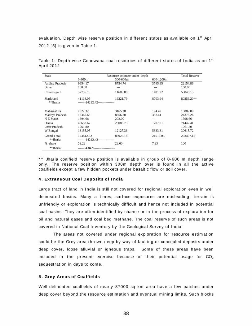
evaluation. Depth wise reserve position in different states as available on 1st April
2012 [5] is given in Table 1.
Table 1: Depth wise Gondwana coal resources of different states of India as on 1st April 2012
State Resource estimate under depth Total Reserve 0-300m 300-600m 600-1200m Andhra Pradesh 9654.17 8754.74 3745.95 22154.86 Bihar 160.00 --- --- 160.00 Chhattisgarh 37755.15 11609.08 1481.92 50846.15
Jharkhand 41118.05 16321.79 8703.94 80356.20** **Jharia -------14212.42---------------
Maharashtra 7522.32 3165.28 194.49 10882.09 Madhya Pradesh 15367.65 8656.20 352.41 24376.26 N E States 1394.66 202.00 --- 1596.66 Orissa 46653.67 23086.73 1707.01 71447.41 Uttar Pradesh 1061.80 --- --- 1061.80 W Bengal 13155.05 12127.36 5333.31 30615.72 Grand Total 173842.52 83923.18 21519.03 293497.15 **Jharia -------14212.42--------------- % share 59.23 28.60 7.33 100 **Jharia -------4.84 %------------------
** Jharia coalfield reserve position is available in group of 0-600 m depth range only. The reserve position within 300m depth over is found in all the active coalfields except a few hidden pockets under basaltic flow or soil cover.
4. Extraneous Coal Deposits of India
Large tract of land in India is still not covered for regional exploration even in well
delineated basins. Many a times, surface exposures are misleading, terrain is
unfriendly or exploration is technically difficult and hence not included in potential
coal basins. They are often identified by chance or in the process of exploration for
oil and natural gases and coal bed methane. The coal reserve of such areas is not
covered in National Coal Inventory by the Geological Survey of India.
The areas not covered under regional exploration for resource estimation
could be the Grey area thrown deep by way of faulting or concealed deposits under
deep cover, loose alluvial or igneous traps. Some of these areas have been
included in the present exercise because of their potential usage for CO2
sequestration in days to come.
5. Grey Areas of Coalfields
Well-delineated coalfields of nearly 37000 sq km area have a few patches under
deep cover beyond the resource estimation and eventual mining limits. Such blocks
38
occur under the influence of intrabasinal faults or subsidence of the basal
formation. In some of the patches whole of Damuda series are found when the
main coal repository – the Barakar formation occurs below 1500 m, while in other
patches, even the top coal bearing formation – Raniganj is overlain by Upper
Gondwana formations. The coals of such patches are not included in resource
estimation. The details of these blocks are of interest because of location, likely
characteristics and their availability for coalbed methane (CBM) exploitation and
may be for carbon dioxide sequestration.
5.1 Jharia Coalfield
Jharia coalfield, the most extensively explored coalfield with nearly 95% proved
reserve within 300 m depth cover is explored up to 1200m depth cover, with prime
coking coal availability within 1050 m depth cover only [6]. Development of
Moonidih mine just within the fringe area of barren measure to 510m depth cover is
intersecting XV seam while the coking coal seam IX may be intersected in the shaft
line at 830m depth cover.
Barren measure up to nearly full thickness of 730m may have to be crossed
to touch the coking coal seams along the periphery of Mahuda block, while within
the Mahuda block overlain by Raniganj formation, the depth of the top most
Barakar seam may be 1800-2000 m deep; beyond mining limit as per any
imagination.
5.2 Raniganj Coalfield
Because of thick fully developed Raniganj formation to 1035 m thickness in
Raniganj coalfield, hardly any effort has been made to touch Barakar formation
underneath 350 m thick Barren Measure along the northern periphery of Raniganj
formation exposure.
5.3 Sohagpur Coalfield
Sohagpur coalfield is divided in northern and southern sections by Chilpa Bahmani
Fault of maximum 600m throw trending E to W running from Burhar to Sonhat
coalfields. As a result, exposed Barakar formation in the southern part is thrown
down in the northern portion of the coalfield. The portion is further complicated
with the exposure of Supra Barakar, Lameta and Deccan trap flow of Upper
Cretaceous age in the north western part [7]. Raniganj formation of 525m
39
thickness has a number of thin coal seams and dolerite sill of variable thickness
[8].
The Barakar formation in this section is buried below 1200 m to 2000 m and
its geological details are not available. Middle Barakar of 150-250 m, the main
repository contains all the important coal seams. The cumulative thickness of the
seams is 15-20m, while in Upper Barakar, the seams in the eastern part has gained
60m thickness at places.
5.4 South Karanpura Coalfield
South Karanpura coalfield in narrow elongated form is developed along the south
boundary fault in folded basin with Bundi Basaria metamorphic inliers. The coalfield
is a half-graben trough in semi-elliptical shape, traversed by basin margin fault and
a number of intrabasinal faults. Central part of the basin has all the sediments of
Damuda group including 600m thick Raniganj and nearly 300m thick barren
measure over the Barakar formation.
5.5 East Bokaro Coalfield
Bokaro coalfield extending over 64 km in east west direction and maximum width
of 11 km in the north south direction is divided in two parts by Lugu Hills in East
and West Bokaro coalfields. The coalfield is traversed by a number of strike and
oblique faults including prominent Gobind pur Pichri Fault.
5.6 Talcher Coalfield
The Talcher coalfield, the southern-most member of the northwest-southeast
trending Mahanadi valley, is the most important coalfield of the Orissa state. It falls
mostly in the Dhenkenal district, with a small part in the Sambalpur district of
Orissa.
6. Concealed coalfields
Concealed areas are of recent discovery and invariably under deep cover,
underneath basalt or alluvial cover. The exact extension of most of these basins is
just indicative by way of geophysical prospective and with skeleton boreholes
drilled for oil and natural gas exploration. The reserve estimates need correction
with every new drilling record. The search for concealed coalfields is made with
40
respect to Damuda sequence of formations within Gondwana sediments. It is
however not certain that every patch with Raniganj formation will definitely have
Barakar formation in sequence after crossing Barren measure.
In most of the cases, the deposits follow established lineament and appear
to be extension of active coal mining areas. Presence of South Gondwana formation
in Bangladesh and intersection of thick coal seams at Singur under 1600 m depth
cover does support the extension of Damodar valley lineament beyond the present
Raniganj coalfield. Concealed coalfields in major Gondwana lineament in Wardha
and Godavari Valley follow identical trend. This has been supported by geophysical
logging and deep hole drilling for oil exploration. The details, i.e. area, seam
distribution and reserve estimate of coal in case of deposits concealed under
basaltic bed or alluvium are not available but the process of their exploration by
non mining agencies in near future is not ruled out.
7. Unmineable coal beds in well-delineated coalfields
The mining limit is decided with due consideration to quality, fuel value, market
demand, market price, basin location and abundance of coal. The limit as such
varies for different grades of coal and location of the coalfields. There is no decided
guideline for making futuristic extrapolation for mining limit but in the light of past
experience and future projection of global technological input, following
conservative suggestions are made. A buffer zone of 100m cap rock is suggested
between the mineable seams and unmineable coal beds to contain gas injected in
the coal beds.
The mining in any basin will be marginally affected by distribution of
different grades of coal and accordingly the operational limit will shift. For example,
in case of Jharia coalfield, the coking nature of bottom most Zero seam may attract
mining beyond the non coking coal seams I-V. Superior grade coal in lower seams
of Raniganj has always encouraged going deeper leaving aside the upper coal
seams. Similarly, the operational limit of power grade coal; accepted to be mined
by open cast may alter in case of coalescing of seam.
The storage characteristic of different beds, the possibility of CO2 injection
along with methane drainage and potential of gas sequestration should be
estimated for unmineable coal seams.
8. Comparative Adsorption of CO2 and Methane
41
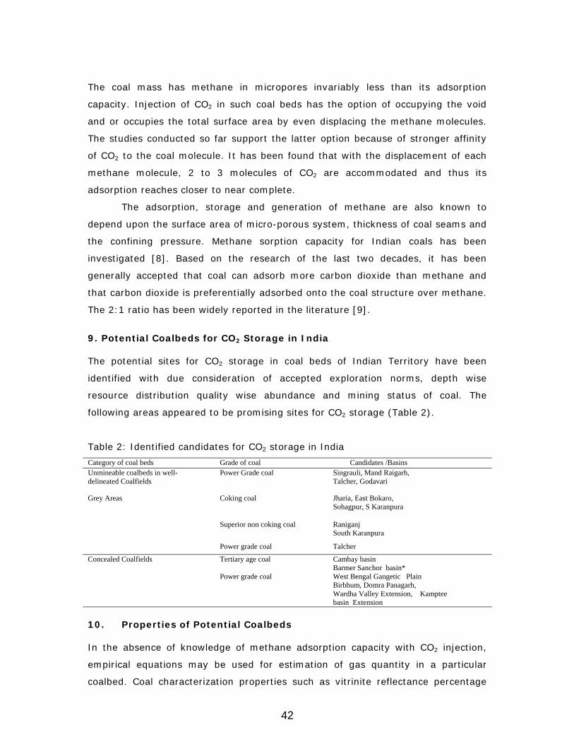
The coal mass has methane in micropores invariably less than its adsorption
capacity. Injection of CO2 in such coal beds has the option of occupying the void
and or occupies the total surface area by even displacing the methane molecules.
The studies conducted so far support the latter option because of stronger affinity
of CO2 to the coal molecule. It has been found that with the displacement of each
methane molecule, 2 to 3 molecules of CO2 are accommodated and thus its
adsorption reaches closer to near complete.
The adsorption, storage and generation of methane are also known to
depend upon the surface area of micro-porous system, thickness of coal seams and
the confining pressure. Methane sorption capacity for Indian coals has been
investigated [8]. Based on the research of the last two decades, it has been
generally accepted that coal can adsorb more carbon dioxide than methane and
that carbon dioxide is preferentially adsorbed onto the coal structure over methane.
The 2:1 ratio has been widely reported in the literature [9].
9. Potential Coalbeds for CO2 Storage in India
The potential sites for CO2 storage in coal beds of Indian Territory have been
identified with due consideration of accepted exploration norms, depth wise
resource distribution quality wise abundance and mining status of coal. The
following areas appeared to be promising sites for CO2 storage (Table 2).
Table 2: Identified candidates for CO2 storage in India Category of coal beds Grade of coal Candidates /Basins Unmineable coalbeds in well- delineated Coalfields
Power Grade coal Singrauli, Mand Raigarh, Talcher, Godavari
Grey Areas
Coking coal
Jharia, East Bokaro, Sohagpur, S Karanpura
Superior non coking coal
Raniganj South Karanpura
Power grade coal Talcher
Concealed Coalfields Tertiary age coal
Cambay basin Barmer Sanchor basin*
Power grade coal West Bengal Gangetic Plain Birbhum, Domra Panagarh, Wardha Valley Extension, Kamptee basin Extension
10. Properties of Potential Coalbeds
In the absence of knowledge of methane adsorption capacity with CO2 injection,
empirical equations may be used for estimation of gas quantity in a particular
coalbed. Coal characterization properties such as vitrinite reflectance percentage
42

and proximate analysis are found to be the relevant parameters affecting the gas
recovery and subsequently CO2 storage in coal beds. These properties for the coal
fields targeted for the said exercise is summarized in Table 3 and 4. Some of the
properties in the same coal fields varied in non coking to coking coals and average
figure has been taken for approximate estimate.
Table 3: Proximate analysis and rank of unmineable and grey area coalbeds Coalfields Basic parameters
(mmf basis) Virinite reflectance
Av. Ro (%)
VM (%)
FC (%)
East Bokaro 28-36 85-90 0.85-1.05 South Karanpura 37-40 80-84 0.60-0.80 Jharia –Barakar 17-35 87-93 0.90-1.30 Raniganj 39-44 79-90 0.70-0.85 Rajmahal-Barakar 38-40 78-81 0.45-0.50 Singrauli- Barakar 37-45 78-81 0.45-0.50 Sohagpur 34-40 80-87 0.55-0.65 Pench valley 32-40 82-89 0.50-0.60 Wardha valley 35-40 78-82 0.55-0.60
Godavari Valley 35-42 78-83 0.55-0.60 Talcher 35-45 79-82 0.50-0.55
*mmf - Mineral matter free basis
Table 4: Proximate analysis and rank of concealed coalbeds Coalfields Basic parameters
(mmf basis) Virinite reflectance
Av. Ro (%) VM
(%) FC (%)
Cambay basin 45-58 52-68 0.32-0.44 Barmer Sanchor Basin 47-60 48-66 0.26-0.40 Birbhum 16-38 68-86 1.10-1.86 Wardha valley 24-35 72-88 0.54-0.68 Kamptee Kanhan valley 26-36 75-92 0.52-0.66 *mmf - Mineral matter free basis
11. Storage Capacity of Coalbeds
CO2 storage capacity of unmineable coal seams for different categories of coalfields
have been discussed below:
11.1 Unmineable Coal Beds in Well-delineated Coalfields
In depth coal resource analysis of Indian territory as per quality, depth wise
distribution and status of exploration has supported in identification of suitable sites
for CO2 sequestration. The resources reported by GSI and other agencies have
been classed as mineable and unmineable on the basis of the following factors.
• Exploration limit of coal has been to 1200m depth cover.
43

• Coking and superior grade non coking up to the explored limit has been
classed as mineable.
• Inferior grade non coking coal (Grade E-G) below 600m depth cover.
• Damodar and Mahanadi Valleys have been taken as within mineable limit.
• Mineable limit for inferior grade non coking coal of Godavari and Wardha
Valleys have been taken as 800m due to premium pricing structure.
The coal beds of Singrauli, Mand Raigarh, Talcher and Godavari valley come
under this class where the coal reserve is available below the mining limit. With a
view to capping injected CO2 in the coal beds, minimum 100m thick top formation
is proposed to be left between the working horizon and non mining zone. The
vitrinite percentage of these sites is low in the range of 40 to 60%, vitrinite
reflectance (VRo%) within 0.4-0.6% and ash within 15-45%, average 35%. The
seams according to these properties are sub bituminous in rank with poor cleat
frequency and aperture. The coal reserve, methane reserve and CO2 storage
capacity for these sites is summarized in Table 5.
Table 5: Unmineable coal reserve and CO2 storage capacity Coalfield Estimated adsorption capacity
of CO2
(m3/t)
Coal Reserve
(Mt)
CO2 storage capacity
(Bm3)
CO2 storage capacity
(Mt)
CO2 storage capacity
(90%) (Mt)
Singrauli Average 20.0 37.0 0.74 1.46 1.32
Mand Raigarh Range 16.0-23.0 average 19.0
79.0 1.50 2.97 2.67
Talcher
Range 17.2-24.8 Average 20.4
1017.0 20.80 41.18 37.06
Godavari Range 16.8-22.2 Average 19.2
1976.0 38.02 75.28 67.75
11.2 Grey Area Coalbeds
The extension of coal beds below 1200m depth cover in coking and superior grade
non coking coal have not been explored even though the continuity of the coal
beds was well indicated within the lineament. The coal beds of such zones beyond
mineable limit have been classed as Grey Area reserve. These reserves in case of
East Bokaro, South Karanpura, Jharia and Raniganj and Sohagpur are below 1200m
depth cover while in case of inferior grade non coking the limit is 600m for Son
Mahanadi Valley and 800m for Wardha Godavari Valley coal fields. The coal and
CBM, recoverable CBM and CO2 storage capacity for these areas is summarized in
Table 6.
44
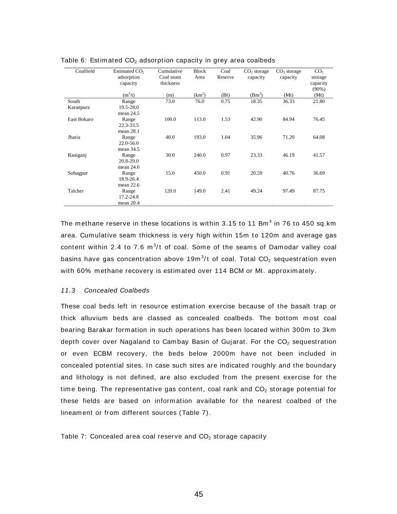
Table 6: Estimated CO2 adsorption capacity in grey area coalbeds Coalfield Estimated CO2
adsorption capacity
(m3/t)
Cumulative Coal seam thickness
(m)
Block Area
(km2)
Coal Reserve
(Bt)
CO2 storage capacity
(Bm3)
CO2 storage capacity
(Mt)
CO2 storage capacity (90%) (Mt)
South Karanpura
Range 19.5-28.0 mean 24.5
73.0 76.0 0.75 18.35 36.33 21.80
East Bokaro
Range 22.3-33.5 mean 28.1
100.0 113.0 1.53 42.90 84.94 76.45
Jharia
Range 22.0-56.0 mean 34.5
40.0 193.0 1.04 35.96 71.20 64.08
Raniganj Range 20.8-29.0 mean 24.0
30.0 240.0 0.97 23.33 46.19 41.57
Sohagpur
Range 18.9-26.4 mean 22.6
15.0 450.0 0.91 20.59 40.76 36.69
Talcher
Range 17.2-24.8 mean 20.4
120.0 149.0 2.41 49.24 97.49 87.75
The methane reserve in these locations is within 3.15 to 11 Bm3 in 76 to 450 sq.km
area. Cumulative seam thickness is very high within 15m to 120m and average gas
content within 2.4 to 7.6 m3/t of coal. Some of the seams of Damodar valley coal
basins have gas concentration above 19m3/t of coal. Total CO2 sequestration even
with 60% methane recovery is estimated over 114 BCM or Mt. approximately.
11.3 Concealed Coalbeds
These coal beds left in resource estimation exercise because of the basalt trap or
thick alluvium beds are classed as concealed coalbeds. The bottom most coal
bearing Barakar formation in such operations has been located within 300m to 3km
depth cover over Nagaland to Cambay Basin of Gujarat. For the CO2 sequestration
or even ECBM recovery, the beds below 2000m have not been included in
concealed potential sites. In case such sites are indicated roughly and the boundary
and lithology is not defined, are also excluded from the present exercise for the
time being. The representative gas content, coal rank and CO2 storage potential for
these fields are based on information available for the nearest coalbed of the
lineament or from different sources (Table 7).
Table 7: Concealed area coal reserve and CO2 storage capacity
45

Coalfield Estimated adsorption capacity (m3/t)
Cumulative Thickness of
the coal seams
(m)
Area of the block
(km2)
Coal reserve
(Bt)
CO2 storage capacity
(Bm3)
CO2 storage capacity
(Mt)
CO2 storage capacity (90%) (Mt)
Cambay basin Range 13.8-19.6 average 16.7
102.0 6900 63.0 1057.81 2094.45 1885.02
Barmer Sanchor Basin
Range 128-18.4 average 15.6
100.0 6700 60.0 936.00 1853.28 1667.95
W.B. Gangetic plain
Range 16.4-23.2 average 18.3
--- --- 7.2 131.76 260.88 234.80
Birbhum coalfield
Range 17.2-24.8 average 20.2
100.0 312.0 4.2 85.08 168.46 151.61
Domra Panagarh Range 18.6-25.8 average 21.8
48.0 116.0 0.751 16.39 32.45 29.20
Wardha Valley extension
Range 15.7-22.8 average 17.8
13.0 212.0 0.37 6.62 13.11 11.80
Kamptee Extension
Range 7.2-9.2 average 8.1
14.0 300 0.57 9.81 19.42 17.48
The gas resources of the above coalfields as estimated are based on presumption
that the saturation level of the coal mass will be nearly 90% during the life time of
the bore wells, with recovery of methane as per best practice. The storage capacity
of some of the candidates are insignificant particularly those of Wardha Kamptee
extensions and unless the limit is precisely delineated, may not be of any use.
Similarly the storage potentials of unmineable beds of Mand Raigarh and Singrauli
are also insignificant and even if ignored may not materially change the situation.
Delineation of concealed coal basins not yet well defined may make difference in
CO2 storage capacity in future. The Barmer Sanchor basin finding is clear example
the latest finding of which has improved the CO2 storage potential.
12. Conclusions
Deeper unmineable coals are prospective candidates for methane recovery with
simultaneous sequestration of CO2 in coalbeds thereby reducing the atmospheric
GHG level and providing a clean source of fuel. Indian coalbeds may be classified
into grey, concealed and unmineable based on its depth of occurrence and grade
characteristics. CO2 sequestration potential in Indian coalbeds is estimated to be
4459 Mt. However, further research on selection of suitable candidates for CO2
46

storage at a specific site demands for a detailed economic appraisal taking into
consideration the daily CO2 generation from the point sources and total gas likely to
be generated during the life time of the power station with the present rate of
consumption of coal.
Acknowledgement
The author is grateful to Dr. T. N. Singh, Former Director, CMRI, Dhanbad for his
valuable advice in preparing this paper. Thanks are also due to Dr. A. Sinha,
Director, CSIR-CIMFR, Dhanbad for granting permission to publish this paper.
References
1. Friedmann SJ, Dooley JJ, Held H, Edenhofer O. The low cost of geological
assessment for underground CO2 storage: Policy and economic implications.
Energy Conversion Management 2006; 1894: 47.
2. Casshyap SM. Patterns of sedimentation in Gondwana basins: Fourth
International Gondwana Symposium., Geological Survey of India, Calcutta,
India January 1977; 525: 2, Hindustan Pub. Corp (India), 1979.
3. Acharyya SK. Comment on``Crustal structure based on gravity-magnetic
modelling constrained from seismic studies under Lambert Rift, Antarctica
and Godavari and Mahanadi rifts, India and their interrelationship'' by DC
Mishra et al. Earth and Planetary Science Letters 2000; 595: 179.
4. Coal Atlas of India. CMPDI, Ranchi (India), 1993.
5. Inventory of Coal and Lignite resources of India as on 01.04.2012.
http://www.portal.gsi.gov.in/gsiDoc/pub/coal_resource.zip
6. Chandra D. Jharia coalfield, Geological Society of India, Bangalore, 1992.
7. Chandra D., Singh RM and Singh MP. Text book of Coal, Tara book Agency,
Varanasi, 2000.
8. Singh AK. Opportunities for Coalbed Methane Exploitation in India, Proc. of
Int. Conf. on Mining Challenges of the 21st Century, New Delhi, November
1999, The Institution of Engineers (India), 369.
9. Chikatamarla L, Bustin MR. Sequestration potential of acid gases in Western
Canadian Coals. Proceedings of the 2003 International Coalbed Methane
Symposium, University of Alabama, Tuscaloosa, Alabama, 5-8 May, 2003, 1.
47
REAL TERM IMPLICATIONS OF CARBON
SEQUESTRATION IN COAL SEAMS V. Vishal
Indian Institute of Technology Bombay Mumbai–400076
Extended Summary
Coal is the source and reservoir of methane gas; the volume of methane stored is
each coal is dependent on many factors. Methane is retained in coals as: adsorbed
molecules on the organic micropores, free gas in pores, cleats and fractures,
dissolved in solution within the coal bed. Injection of CO2 in coal seams may be
carried out to extract methane through the fracture network in the coal. CO2 has an
additional effect compared to other gases that it is preferentially adsorbed onto coal
surfaces, displacing methane from adsorption sites. CO2-ECBM sequestration is a
value addition project in management of increasing atmospheric concentration of
GHGs as it recovers the cost of capture, processing, transportation and storage of
CO2 by production of methane. Therefore, coal seam sequestration may be defined
as the storage of CO2 from anthropogenic sources into deep, unmineable coal
seams for geologically significant limits with or without concomitant recovery of
natural gas (White et al., 2005).
The challenges in coal seam sequestration are many folds and various
research works on field and laboratory scale are being carried out to understand
the reservoir behaviour. Several pilot scale studies for injection of CO2 is under
operation in different fields like Ishikari Basin, Japan and North Dakota, USA. Most
of these basins have experienced loss in injectivity due to reduction in coal
permeability with time. The decline may be attributed to the CO2 adsorption
induced swelling in coal mass which leads to closure of macroporosity (i.e. cleats)
since CO2 in supercritical form induces maximum volumetric deformation in coal
(Peters et al., 2000). It is important to understand the response of coal in detail
before implementation of the sequestration process on a field scale. Not many
studies have been carried out on investigating the behaviour of Indian coal with
CO2 in terms of the real term coal-CO2 interactions. The role of effective stresses,
confining stresses, coal matrix deformation etc. on CO2 permeability of Indian
bituminous coal was found in a recent article by Vishal et al. (2013a). The results
48
reveal that coal undergoes swelling and at higher depths, permeability reduces
significantly, thereby altering the complete process of sequestration. Phase
transformation of injected CO2 at such depths may also lead to changes in coal-CO2
interactions, finally influencing the injectivity of gases. Further, the influence of gas
injection on the strength characteristics of coal as well as surrounding rock must be
investigated for overall stability and safety of the system. Cap rock integrity is one
of the most important parameters for sequestration of green house gases and must
be understood in greater details before actual implementation.
However, applications of carbon capture and storage (CCS) in coal seams
have its own advantages and thus, focus on coal research for sequestration has
gained attention over time. The mechanism of storage in coal being adsorption is
safer as compared to the compressional mechanism in conventional hydrocarbon
reservoirs. The preferred affinity of coal for CO2 over methane may be utilized for
enhanced recovery of CBM from the coal blocks. Simulation works have indicated
that injection of CO2 may be used to recover more than 90% of coalbed methane
which during primary recovery only enable upto 40-50% of gas extraction. Vishal et
al. (2013b) worked out the CO2-ECBM recovery for a block of coal seam in Raniganj
coalfield for a preliminary investigation of the process using numerical simulation.
The results indicate a positive connotation for the feasibility of the process, with
keeping in mind the assumptions and the constraints in their work.
Therefore, to meet the growing energy needs, CCS in coal not only provides
opportunity for capturing low carbon fuel, i.e. methane but also partly meets with
the commitment of reduction of greenhouse gases (GHG) emission into the
atmosphere. The process of ECBMR shall also partly offset the cost of carbon
capture, transportation and storage in coal and hence, CCS in coal may be a value-
addition process as compared to other storage methods in saline aquifers or
basaltic formations. Understanding the behaviour of coal in underground scenarios
is the key to successful operations and if established, coal seam sequestration
would lead its way to GHG release mitigation in future.
References
1. Peters, J., Punjrath, N.K., Singh, S.K., 2000, Development of coalbed
methane resources–challenges in the new millennium, Indian Geol Cong,
KDMIPE, Dehradun.
49
2. Vishal, V., Ranjith, P.G., Singh, T. N., 2013a, CO2 permeability of Indian
bituminous coals: Implications for carbon sequestration, International
Journal of Coal Geology. doi: 10.1016/j.bbr.2011.03.031
3. Vishal, V., Singh, L., Pradhan, S. P., Singh, T. N., Ranjith, P.G., 2013b,
Analog modeling of Gondwana coal seams in India as coalbed methane
reservoirs substituted for carbon dioxide sequestration, Energy, doi:
10.1016/j.energy.2012.09.045
4. White, C.M., Smith, D.H., Jones, K.L., Goodman, A.L., Jikich, S.A., LaCount,
R.B., DuBose, S.B., Ozdemir, E., Morsi, B.I., Schroeder K.T., 2005,
Sequestration of carbon dioxide in coal with enhanced coalbed methane
recovery: a review, Energy Fuel, 19(3), 659–724.
50
CARBON DIOXIDE STORAGE AND
ENHANCED OIL RECOVERY Gautam Sen
ONGC Energy Centre, Delhi-110092
Abstract
Capturing and storing CO2 from the atmosphere is becoming essential in view of
the large increase of CO2 from anthropogenic activities. Sub-surface geology
provides the best medium for storage of excess CO2 either in depleted oil and gas
fields or in saline aquifers. EOR or enhanced oil recovery is a tertiary method after
natural depletion and water injection methods have been applied to the oil field.
Carbon Dioxide is injected into an oil bearing stratum under high pressure. Miscible
CO2 interacts with the reservoir oil resulting in low viscocity, low interfacial tension
and therefore higher mobility. This therefore reduces the residual oil saturation.
Recent changes in EOR technology incorporate very large volume of injected
carbon dioxide (1 to 1.5 Hydrocarbon pore volume HCPV), better mobility control
through alternate use of gas and water, advanced and optimized infill well drilling
and completion to target reservoir above oil water contact and bypassed oil zones
left unswept during the secondary water injection stage. Rigorous monitoring of
reservoir fluid either through pressure studies in slim hole for thinner reservoirs or
time lapse seismic for seismically resolvable reservoirs is a significant approach in
recent times.
139 Gega tones of CO2 has been injected in the subsurface with an
average of 0.30 tonnes/bbl as the CO2/oil ratio at the time of report in 2009.India
needs to take up EOR methods more vigorously though ONGC has initiated the
process. Gujarat, Assam and Rajasthan can be the pioneers in this effort depending
on the type of oil.
1. Introduction
Carbon Dioxide –enhanced oil recovery technology have been commercially
deployed in old oil fields mainly in the United States of America [1] for the last
three decades. Anthropogenic sources of CO2 are steadily increasing in developed
countries as the source in contrast to the natural sources, which were the only
source historically. Pipeline network of CO2 and identification of CO2 sink i.e. the old
51

oil field or saline aquifer in subsurface if storage is the only objective, is necessary
for deployment of this technology. Ability to produce incremental oil and therefore
enhanced revenue, through injection of high pressure CO2 gas has made this option
financially attractive.
Sedimentary basins across the globe are the habitat for oil and gas fields
and coal seams. Deeper saline aquifers can also be found in Sedimentary basins.
Basin is a depocentre in the Earth’s crust formed due to tectonic forces either in
extensional or compressional or in Strike slip regime. Sedimentary rocks
transported from highlands by water system deposits in this basin and the process
continues with increased subsidence either by gravity or by renewed tectonic
activity. Insitu, organic growth of carbonate reefs is also possible under favorable
environment. Sandstones, Carbonates rocks usually have pores and they are either
filled with saline aquifers or in some cases hydrocarbons. Coal also gets deposited
in sedimentary basins and coal seams can entrap fluids particularly gases. It is
important that this fluid do not escape back into the atmosphere and therefore top
and lateral seals are necessary and usually impermeable rocks like shale/
salts/evaporates or tight limestone provides seal. Depleted Oil fields and saline
aquifers thus provide habitat for injected CO2 in a sedimentary basin. Seismic data
provides the subsurface image of sedimentary basin and can indicate possible
habitats for injected CO2.
A recent global study carried out using analog from US experience indicate
that over fifty [2] large oil basins have reservoirs amenable for miscible CO2
injection which can potentially produce 470 billion barrel of additional oil and store
140 billion metric tons of carbon dioxide. Half of these basins are in Africa and
Middle East. Around 300,000 barrels of oil per day is being produced in USA mainly
in Permian Basin located around Texas from enhanced oil recovery through 60 MM
tones of CO2 injection of which 20% is from anthropogenic sources. Extensive CO2
pipeline network exists and the sinks i.e. candidate for injection is well defined
including replacements. The process of water alternating gas injection manages the
supply demand of CO2 at individual field level by and shuts off CO2 injection incase
supply exceeds demand. European Union, Canada, Australia and even some of the
BRICS countries are also following suit.
Saline aquifers can store much larger volumes of CO2, due to its abundance,
but the ability to produce incremental oil with injection of carbon dioxide in a
matured oil field offsets the costs associated with carbon capture and storage.
52
Additionally the geology of oil reservoirs is well understood unlike reservoirs with
saline aquifers where leakage of CO2 back into the atmosphere can pose a serious
problem, unless trapping mechanism exists. However estimating performance of
injected carbon dioxide in enhancing oil recovery is complex and data intensive and
each oil field could be very different.
EOR or enhanced oil recovery is a tertiary method after natural depletion
and water injection methods have been applied to the oil field. Carbon Dioxide is
injected into an oil bearing stratum under high pressure. Miscible CO2 interacts with
the reservoir oil resulting in low viscosity, low interfacial tension and therefore
higher mobility. This therefore reduces the residual oil saturation. The challenge is
to increase area of contact of the two phases. In case of immiscible CO2 with
reservoir oil, due to low reservoir pressure or heavy or too light oil, mobility still
increase due to oil phase swelling and viscosity reduction of the mixture in some
instances. CO2 produced along with hydrocarbon particularly in miscible case is
separated and recycled back into the oil reservoir.
Recent changes in EOR technology incorporate very large volume of injected
carbon dioxide (1 to 1.5 Hydrocarbon pore volume HCPV), better mobility control
through alternate use of gas and water, advanced and optimized infill well drilling
and completion to target reservoir above oil water contact and bypassed oil zones
left unswept during the secondary water injection stage. Rigorous monitoring of
reservoir fluid either through pressure studies in slim hole for thinner reservoirs or
time lapse seismic for seismically resolvable reservoirs is a significant approach in
recent times. There is also a possibility of increasing geological storage of CO2 into
the saline aquifer once the oil has been produced. Industrializing the process would
include a steady supply of CO2 through pipelines and selection of large number of
oil fields as sink candidates, including identification of their replacements when oil
production from a field becomes financially unviable.
2. Case Studies from USA and Canada (source: Global Technology Roadmap)
The Permian Basin of southwest Texas and southeast New Mexico [3] is one of the
largest and most active oil basins in the United States, with the entire basin
accounting for approximately 17 percent of the total United States oil production
with OXY as the main operator. Approximately two-thirds of Oxy’s Permian Basin oil
production is from fields that actively employ carbon dioxide (CO2) flooding, an
enhanced oil recovery (EOR) technique in which CO2 is injected into oil reservoirs,
53

causing the trapped oil to flow more easily and efficiently. Oxy is an industry leader
in applying this technology, which can increase ultimate oil recovery by 15 to 25
percent in the fields where it is employed in the Permian. Each year, Oxy inject
more than 550 billion cubic feet of CO2 into oil reservoirs in the Permian, making
Oxy the largest injector of CO2 for EOR in the United States and a world leader in
this technology.
To ensure an adequate supply of CO2 for EOR operations in the Permian,
Oxy relies upon several sources. These include carbon dioxide produced from the
Oxy-operated Bravo Dome field in northeastern New Mexico, and additional
supplies from methane fields in the southwestern Permian. The Century Plant in
Pecos County, Texas, further expands Oxy’s EOR infrastructure in the Permian
Basin. The plant processes natural gas with high-CO2 content, resulting in methane
gas for the market as well as a major new source of CO2 for Oxy’s Permian
operations.
The principal reservoirs are Carbonate shelf and platform strata with
variable porosity and low permeability. Primary recovery efficiencies were low
between 10 to 20% of OOIP. Water flooding started in 1950’s and CO2 injection
commenced in large fields in 1970s. Recovery has gone up to 50% in some of the
large fields with CO2 injection. A recent USGS analysis indicates that the largest
reservoirs –the San Andres, Grayburg and Canyon have contributed to this growth
in oil reserves in the preceding decade. Deeper and smaller reservoirs can also be
taken up but with lower gain. The main reservoirs studied by USGS have a potential
to further add a mean of 2.68BBO of reserves through water flooding and CO2
injection.
54
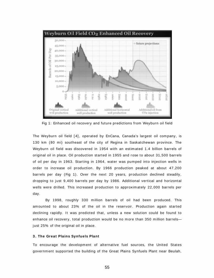
Fig 1:
The Weybu
130 km (8
Weyburn o
original oil
of oil per d
order to in
barrels per
dropping to
wells were
day.
By
amounted
declining r
enhance oi
just 25% o
3. The Gre
To encoura
governmen
Enhanced o
urn oil field
80 mi) sout
oil field was
in place. Oi
day in 1963
ncrease oil
r day (Fig
o just 9,400
drilled. Th
1998, roug
to about 2
apidly. It w
l recovery,
of the origina
eat Plains S
age the de
nt supported
oil recovery
[4], opera
theast of th
s discovered
il production
3. Starting i
production
1). Over t
0 barrels pe
is increased
ghly 330 m
23% of the
was predicte
total produ
al oil in plac
Synfuels P
evelopment
d the buildin
and future
ted by EnC
he city of R
d in 1954 w
n started in
n 1964, wa
n. By 1966
the next 20
er day by 1
d production
million barr
e oil in th
ed that, unl
ction would
ce.
lant
of alterna
ng of the G
predictions
Cana, Canad
Regina in S
with an estim
1955 and r
ater was pu
production
0 years, pr
1986. Additi
n to approx
rels of oil
e reservoir
less a new
be no mor
ative fuel s
reat Plains
s from Weyb
da’s largest
askatchewa
mated 1.4
rose to abou
mped into i
n peaked a
roduction d
ional vertica
ximately 22
had been
r. Productio
solution co
re than 350
sources, the
Synfuels Pla
burn oil field
t oil compan
an province
billion barre
ut 31,500 ba
injection we
at about 47
eclined ste
al and horiz
,000 barrel
produced.
on again st
ould be fou
million bar
e United S
ant near Be
d
ny, is
. The
els of
arrels
ells in
7,200
adily,
zontal
s per
This
tarted
nd to
rels—
States
eulah,
55

North Dako
methane (C
is fed into
burned at a
a mixture o
Then it is p
natural ga
(CO2).
The
to custome
plants relea
effect and
km (205 m
helps to pr
4. The We
In 1997, th
gas (96%
Weyburn o
ota. Comme
CH4) from c
“gasifiers”
a temperatu
of gases. Th
passed thro
s (SNG)—m
daily produ
ers, and 13,
ase their wa
global warm
mi) pipeline
oduce more
Fig
eyburn CO2
he Dakota G
CO2) from
il field.
ercial opera
coal. Every d
where it is
ure of 1200°
he gas is co
ugh methan
mostly CH4—
uction is 3,0
,000 tons o
aste gas int
ming. Waste
to Weyburn
e oil (Fig 2).
g 2: Well gri
2 Enhanced
Gasification
its Great
ations starte
day, more t
mixed with
°C (2200°F)
ooled to con
nol at -70°C
—from othe
050 tons of S
f waste gas
to the atmos
e gas from t
n, where it
id structure
d Oil Recov
Company (
Plains Syn
ed in 1984
han 16,000
h steam and
). This break
dense tar, w
C (-94°F). T
er compoun
SNG, which
s, 96% of w
sphere, con
the Great P
not only is
in Wyeburn
very Operat
(DGC) agre
fuels Plant
. The goal
0 tons of cru
d oxygen a
ks down the
water, and
This separat
nds—mostly
is fed throu
which is CO2
ntributing to
Plains plant
disposed o
n project
tion
eed to send
through a
was to pro
ushed lignite
nd then pa
e coal to pro
other impur
tes the synt
y carbon di
ugh gas pipe
2. Many Syn
o the greenh
is fed into a
of safely but
all of the w
pipeline to
oduce
e coal
rtially
oduce
rities.
thetic
oxide
elines
nfuels
house
a 330
t also
waste
o the
56
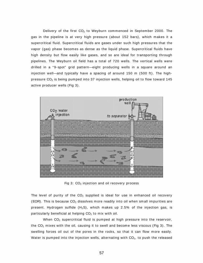
Deli
gas in the
supercritica
vapor (gas
high densit
pipelines. T
drilled in a
injection w
pressure C
active prod
The level o
(EOR). This
present. H
particularly
Whe
the CO2 mi
swelling fo
Water is pu
very of the
pipeline is
al fluid. Sup
) phase bec
ty but flow
The Weybu
a “9-spot”
well—and ty
O2 is being
ducer wells (
Fig
of purity of
s is because
ydrogen su
y beneficial a
en CO2 supe
ixes with th
rces oil out
umped into
e first CO2 t
at very hi
percritical flu
comes as d
easily like
rn oil field
grid patter
pically have
pumped int
(Fig 3).
g 3: CO2 inje
f the CO2 s
e CO2 dissolv
ulfide (H2S),
at helping C
ercritical flu
e oil, causin
t of the por
the injectio
to Weyburn
gh pressure
uids are gas
ense as the
gases, and
has a total
n—eight pr
e a spacing
to 37 injecti
ection and o
upplied is i
ves more re
, which ma
CO2 to mix w
uid is pump
ng it to swe
res in the r
n wells, alte
n commence
e (about 15
ses under s
e liquid pha
d so are ide
of 720 we
roducing we
of around
on wells, he
oil recovery
deal for us
eadily into o
akes up 2.5
with oil.
ed at high
ll and becom
rocks, so th
ernating wit
ed in Septe
52 bars), w
such high pr
se. Supercr
eal for trans
ells. The ve
ells in a sq
150 m (50
elping oil to
process
se in enhan
oil when sm
5% of the
pressure in
me less visc
hat it can fl
th CO2, to p
ember 2000
which makes
ressures tha
ritical fluids
sporting thr
rtical wells
quare aroun
00 ft). The
flow toward
nced oil reco
all impuritie
injection ga
to the rese
cous (Fig 3)
low more e
push the rele
. The
s it a
at the
have
rough
were
nd an
high-
d 145
overy
es are
as, is
ervoir,
). The
easily.
eased
57
oil toward producer wells. Some CO2 comes back out of the ground at producer
wells. This is recycled, compressed, and reinjected along with gas from the
pipeline.
It is predicted that the CO2 EOR operation will enable an additional 130
million barrels of oil to be produced, extending the field’s commercial life by
approximately 25 years. It is also anticipated that about 20 million tons of CO2 will
be injected and become permanently stored 1,400 m (4,600 ft) underground over
the lifetime of this project. There is worldwide interest in this test of the viability of
underground storage for large-scale reduction in CO2 emissions to the atmosphere.
The Weyburn CO2 Monitoring and Storage Project is funded by several international
energy companies, the U.S. and Canadian governments, and the European Union.
The main concern is whether the CO2 will stay in place.
Weyburn is an excellent test site because, since 1955, thorough geological
tests have been made and the results stored. There are rock core samples from
1,200 boreholes, plus time-lapse seismic analysis and borehole logging.
Researchers are also sampling groundwater to test for CO2 leaks in wells. So far, no
leaks have been detected and none of the gas has escaped to the surface. The
Canadian government believes that CO2 storage deep underground will help it to
meet its targets under the 1997 Kyoto Protocol, which requires a reduction in
greenhouse gas emissions by an average of 5% between 2008 and 2012. In the
case of Weyburn, the CO2 is from coal that came from under the ground, so it is
effectively being put back where it came from.
Another CO2 capture and storage project currently under way is in the
Sleipner field [5] in the North Sea in the Norwegian region. Injection commenced in
1996 with CO2 separated from natural gas and injected into the Utisara sand a
saline aquifer of late Cenozoic age at a depth of 1012m below sea bed, around
200m below reservoir top with a storage of over 11 mmt. Time lapse surveys have
been carried out with 3D surveys in 1994, 1999, 2001, 2002, 2004, 2006, 2008
etc. The CO2 plume is seen in seismic as a number of sub horizontal reflectors of
tuned wavelets arising from thin layers of CO2 trapped beneath thin intrareservoir
mudstone and the reservoir cap rock and growing in time. There is also a velocity
pull down in reflectors below the plume. A post stack Stratigraphic inversion of the
1994 and 1996 provided p wave impedance. Prestack inversion of the 1994 and
2006 data sets (after injecting 8.4mmt) with 50 iteration in the window 750-1400
ms provided s wave impedance and refined p wave impedance. This results when
58
combined with spectral decomposition gave an idea of the thickness of CO2 layers
thus making it possible to make a volumetric estimate of CO2 in the subsurface.
5. Monitoring / Flow Surveillance
Acoustic and elastic impedance contrast between the overlying and underlying rock
strata and the reservoir rock provides the basis for subsurface imaging of the
reservoir. While the longitudinal wave (P wave) is sensitive to the pore fluid, the
transverse wave (shear wave) bypasses the pore and therefore is insensitive to
presence of fluid. Gassman’s equation provides a relationship between P wave
velocity, S wave velocity, average density of matrix and fluid, porosity and elastic
constants of rock matrix and fluid. Fluid substitution assuming constant shear
modulus and constant porosity can help in modeling the change in p wave velocity
with injected CO2.
Laboratory studies along with well calibrated seismic parameters and using
Gassman’s equation can provide sensitivity analysis of seismic velocity (p wave)
with pressure and saturation of injected CO2. Thus with a baseline 3D survey prior
to CO2 injection, and then with 3D survey repeated periodically along with injected
CO2 and production and interpreting changes in subsurface as per the template
designed as above, calibrated with saturation logs in time lapse mode, it is possible
to quantify enhance oil recovered, both above the oil water contact as well as in
bypassed zones in isolated pools. Additionally, inversion of pre stack seismic data
composed of reflections from different offsets can throw further light into the
change in subsurface with injected CO2 and enhanced production.
Reflection coefficient of non zero offset seismic wave at an interface depends
on the contrast in acoustic impedance along with the contrast in Poisson’s ratio
(which is essentially a function of the ratio of p wave and shear wave velocity) of
the overlying and underlying bed. Thus AVO (amplitude VS offset of P waves)
behavior of the reservoir also changes with injected CO2 and production of oil.
Incase this behavior is calibrated with well data and based on rock physics
modeling; the changes could help in understanding fluid movement.
However this is easier said than done for artifacts in acquisition of seismic
data and processing of seismic data can easily mar the assumption of repeatability.
Three factors namely Earth effects, acquisition related effects and noise, changes
seismic amplitudes.
59
Earth effects [6] include spherical divergence, absorption, transmission
losses, interbed multiples, converted waves, tuning, anisotropy and structure.
Acquisition related effects include source and receiver arrays and receiver
sensitivity. Noise can be ambient or source generated, coherent or random.
Processing attempts to alleviate problems of non repeatability, but can in the
process create amplitude distortion and even now algorithms used are still not
without their limitation in preserving amplitudes. 3D surveys done at different time
are processed with the same processing parameters and same sequence. At each
step at the non reservoir zone data is matched through time and space variant
amplitude and spectral trace matching after correcting for time shifts if any due to
variation in near surface between the surveys.
This process can reasonably ensure that at the non reservoir level, the time
lapse surveys match and differences over and above this at the reservoir level can
only be ascribed as signal attributed to injected CO2 and enhanced production.
Quantification of enhanced production and the economics can then only be on a
firmer footing. Disadvantages of carbon sequestration through EOR vis a vie
injecting CO2 in saline aquifer is their geographic distribution of old oil fields and
their limited capacity as well as the fact that subsequent burning of the additional
oil so recovered will offset much or all of the reduction in CO2 emissions. Flat spots
in Seismic if detectable, created due to oil water contact pre injection of CO2 can
also be of great help for this will move vertically in repeated seismic, along with
enhanced recovery
The discussion so far assumed that CO2 is inert [7] and it does not affect the
rock matrix. However this is not always the case and its effect also needs to be
discussed. Temperature and pressure conditions in subsurface will keep CO2 in a
liquid state. Under this condition if CO2 replaces water without dissolving in it the
bulk modulus and density would decrease. When supercritical CO2 migrates upward
it moves to sub critical state and this may alter the free and dissolved gas ratio,
affecting fluid saturation and distribution of patchy VS homogenous saturation.
Changes in p wave velocity with increase in saturation of CO2 are very different for
the two cases below 70 deg saturation. Reduction in velocity of P wave is much
faster for homogenous saturation as compared to patchy saturation, and therefore
unless lab studies of core provide type of saturation data, interpretation of lowering
of VP to saturation of CO2 directly can be vastly erroneous. A 3% enhancement in
porosity due to dissolution of mineral in CO2 causes the same reduction in VP as
60

70% enhancement in CO2 saturation. Thus non inert CO2 is a difficult case for a
Quantative estimation of injected CO2.
Shear wave data may help to differentiate dissolution from saturation
effects. With injection of CO2 there is an increase in VS due to lowering of density in
the inert case while chemical dissolution causes a decrease in VS due to lowering of
rigidity modulus. Also the behavior of VS is independent of type of saturation,
patchy vs. uniform for shear wave bypasses fluid. The challenge is to acquire good
quality shear wave data, particularly in 4D sense. Combining both V p and Vs
particularly using time lapse survey, backed up with extensive core data can
provide a better quantitative estimation. Vertical Seismic profiling i.e. VSP carried
out in 3D sense can provide a higher resolution data for it involves only one way
wave propagation unlike surface seismic which has two way wave propagation.
Static errors due to near surface irregularities are also much more pronounced in
surface seismic data for shear wave acquisition.
We can conclude by stating that monitoring of multiphase subsurface flow
associated with CO2 injection poses new challenges because of complex seismic
response of CO2 water rock systems. Conventional models for seismic signatures
like Gassman’s model, based on fluid substitution, are mechanical and cannot
incorporate chemical changes to host rock thereby altering porosity or formation of
patchy porosity on account of change of state from super critical to sub critical.
Thus magnitude and sense of changes in VP and Vs together, in time lapse
seismic/VSP backed up with laboratory studies of core may help in Quantative
estimate of injected CO2 and each case can be unique depending on the interaction
of CO2 with water and host rock.
IEA [2] has prepared a detailed compilation of the estimates of original oil in
place, ultimate primary and secondary recovery, incrementally technically
recoverable oil from CO2-EOR and the volume of CO2 stored in association with this
process in fifty world basins with favorable conditions for miscible CO2. Basins are
located in USA, Canada, Russia, China, Middle East, Africa, Latin America, and
Australia. This process is cheaper in onshore but large oil field in offshore like Brazil
can be ideal candidates in storing CO2 in pre salt reservoir.
139 Gega tones of CO2 has been injected in the subsurface with an average
of 0.30 tonnes/bbl as the CO2/oil ratio at the time of report in 2009. India needs to
take up EOR methods more vigorously, though ONGC has initiated the process.
61
Gujarat, Assam and Rajasthan can be the pioneers in this effort depending on the
type of oil.
6. Conclusions
Capturing and storing CO2 from atmosphere is essential for saving the planet in
view of the large increase of CO2 through anthropogenic source. This naturally
upsets the normal Carbon cycle. Subsurface Geology provides the best medium for
storage of excess CO2 either in old oil and gas field or in saline aquifer. Depleted
fields have an advantage for the geology is well known, infrastructure exists and
injected CO2 can enhance recovery, thereby making the project financially
attractive. It has to be ensured that injected CO2 does not leak back to the
atmosphere and entrapment mechanism is known for oil and gas field unlike saline
aquifer. However the potential to store CO2 is far greater in the saline aquifer and is
ubiqtous.
Monitoring movement of injected CO2 can be done by using time lapse
surface or down hole survey carried out in 3D sense and both P wave and shear
wave studies would be required to make a volumetric estimate. Incase CO2 is inert
the interpretation would be relatively simpler else alteration of petro physical
characteristic of the host rock and the type of porosity data from extensive cores
using SEM studies would be required as input for interpreting time lapse data. It
can be concluded [8] that Quantative interpretation of repeated 3D data for
monitoring and volumetric computation of the stored CO2 depends on the rock
physics model. VP and VS and amplitude changes with respect to CO2 saturation in
reservoir condition of temperature and pressure, needs to be studied and each case
is unique in its own way.
References
1. National Energy Technical Laboratory (2010) Carbon Dioxide Enhanced Oil
Recovery, US Department of Energy Report.
2. Michael L Godec et al (2011) Global Technology Roadmap for CCS in
industry Sectorial Assessment, CO2 Enhanced Oil Recovery Advanced
Resources International Inc Report.
3. Marilyn E Tennyson et al (2012) Assessment of Remaining recoverable Oil in
selected major Oil fields of Permian basin, Texas and New Mexico, USGS
Report.
62
4. Jinfeng MA (2010) AVO modeling of pressure saturation effects in Weyburn
CO2 sequestration, Leading edge, SEG publication.
5. Andy Chadwick et al (2010) Quantative analysis of time lapse seismic
monitoring data at the Sleipner CO2 storage operation, Leading edge, SEG
publication.
6. M Bacon, R Simm, and T Redshaw (2003) 3-D seismic interpretation,
Cambridge University press.
7. TizanaVanoria et al (2010) The Rock Physics basis for 4D monitoring of CO2
fate: Are we there yet, Leading edge, SEG publication.
8. Per Avseth, Tapan Mukherji, and Gary Mavko (2008) Quantative Seismic
Interpretation, Cambridge University Press.
63
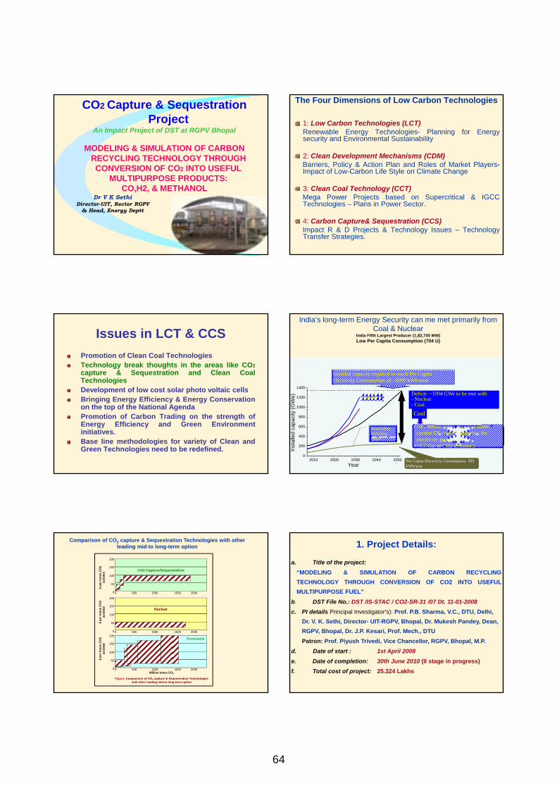
CO2 Capture & Sequestration Project
An Impact Project of DST at RGPV Bhopal
MODELING & SIMULATION OF CARBON RECYCLING TECHNOLOGY THROUGH CONVERSION OF CO2 INTO USEFUL
MULTIPURPOSE PRODUCTS: CO,H2, & METHANOL
Dr V K Sethi Director-UIT, Rector RGPV
& Head, Energy Deptt
The Four Dimensions of Low Carbon Technologies 1: Low Carbon Technologies (LCT)
Renewable Energy Technologies- Planning for Energy security and Environmental Sustainability 2: Clean Development Mechanisms (CDM)
Barriers, Policy & Action Plan and Roles of Market Players- Impact of Low-Carbon Life Style on Climate Change 3: Clean Coal Technology (CCT)
Mega Power Projects based on Supercritical & IGCC Technologies – Plans in Power Sector. 4: Carbon Capture& Sequestration (CCS)
Impact R & D Projects & Technology Issues – Technology Transfer Strategies.
Issues in LCT & CCS Promotion of Clean Coal Technologies Technology break thoughts in the areas like CO2 capture & Sequestration and Clean Coal Technologies Development of low cost solar photo voltaic cells Bringing Energy Efficiency & Energy Conservation on the top of the National Agenda Promotion of Carbon Trading on the strength of Energy Efficiency and Green Environment initiatives. Base line methodologies for variety of Clean and Green Technologies need to be redefined.
4 4
India’s long-term Energy Security can me met primarily from
Coal & Nuclear India Fifth Largest Producer (1,82,700 MW) Low Per Capita Consumption (704 U)
Deficit: ~1094 GWe to be met with - Nuclear - Coal
Per Capita Electricity Consumption: 593 kWh/year
2010 2020 2030 2040 20500
200
400
600
800
1000
1200
1400
Inst
alle
d ca
paci
ty (G
We)
Year
Demand
Renewables including hydro
Installed capacity required to reach Per Capita Electricity Consumption of ~5000 kWh/year
• ~4.7 billion tonne /year [>4 times current US coal consumption for electricity generation]
• ~7.7 Gte of CO2 emissions
Coal
CO2 Capture/Sequestration
200
150
100
50
0 0 500 1000 1500 2000
Nuclear
200
150
100
50
0 0 500 1000 1500 2000
Renewable 200
150
100
50
0 0 500 1000 1500 2000 Million tones CO2
Figure: Comparison of CO2 capture & Sequestration Technologies
with other leading mid-to long-term option
$ pe
r ton
ne C
O2
avoi
ded
$ pe
r ton
ne C
O2
avoi
ded
$ pe
r ton
ne C
O2
avoi
ded
Comparison of CO2 capture & Sequestration Technologies with other leading mid-to long-term option 1. Project Details:
a. Title of the project: “MODELING & SIMULATION OF CARBON RECYCLING TECHNOLOGY THROUGH CONVERSION OF CO2 INTO USEFUL MULTIPURPOSE FUEL”
b. DST File No.: DST /IS-STAC / CO2-SR-31 /07 Dt. 11-01-2008 c. PI details Principal Investigator's): Prof. P.B. Sharma, V.C., DTU, Delhi,
Dr. V. K. Sethi, Director- UIT-RGPV, Bhopal, Dr. Mukesh Pandey, Dean, RGPV, Bhopal, Dr. J.P. Kesari, Prof. Mech., DTU
Patron: Prof. Piyush Trivedi, Vice Chancellor, RGPV, Bhopal, M.P. d. Date of start : 1st April 2008
e. Date of completion: 30th June 2010 (II stage in progress) f. Total cost of project: 25.324 Lakhs
64
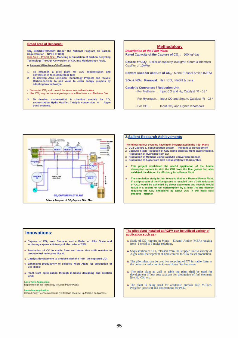
Broad area of Research: CO2 SEQUESTRATION (Under the National Program on Carbon Sequestration – NPCS of DST) Sub Area – Project Title: Modeling & Simulation of Carbon Recycling Technology Through Conversion of CO2 Into Multipurpose Fuels.
g. Approved Objectives of the Proposal: 1. To establish a pilot plant for CO2 sequestration and conversion in to multipurpose fuel. 2. To develop Zero Emission Technology Projects and recycle
Carbon-di-oxide to add value to clean energy projects by adopting two pathways:
Sequester CO2 and convert the same into fuel molecules. Use CO2 to grow micro algae to produce Bio-diesel and Methane Gas.
3. To develop mathematical & chemical models for CO2 sequestration, Hydro Gasifier, Catalytic conversion & Algae pond systems.
Methodology Description of the Pilot Plant:- Rated Capacity of the Capture of CO2 : 500 kg/ day Source of CO2: Boiler of capacity 100kg/hr. steam & Biomass Gasifier of 10kWe Solvent used for capture of CO2 : Mono Ethanol Amine (MEA) SOx & NOx Removal: Na H CO3, NaOH & Lime. Catalytic Converters / Reduction Unit - For Methane.... Input CO and H2, Catalyst “R - 01 * - For Hydrogen.... Input CO and Steam, Catalyst “R - 02 * - For CO ... Input CO2 and Lignite /charcoals
Scheme Diagram of CO2 Capture Pilot Plant
2.Salient Research Achievements
The following four systems have been incorporated in the Pilot Plant: 1. CO2 Capture & sequestration system – Indigenous Development 2. Catalytic Flash Reduction of CO2 using charcoal from gasifier/lignite.
Production of Hydrogen from CO 3. Production of Methane using Catalytic Conversion process 4. Production of Algae from CO2 Sequestration with Solar flux.
This project revalidated the useful application of the Amine absorption system to strip the CO2 from the flue gasses but also validated the data on its efficiency for a Power Plant.
The simulation study further revealed that in a Thermal Power Plant,
if a slip stream of the Flue gasses is recycled then a 30% reduction of CO2 would be achieved by direct abatement and recycle would result in a decline of fuel consumption by at least 7% and thereby reducing the CO2 emissions by about 36% in the most cost effective manner.
Innovations:
Capture of CO2 from Biomass and a Boiler on Pilot Scale and achieving capture efficiency of the order of 78%
Production of CO in stable form and Water Gas shift reaction to produce fuel molecules like H2
Catalyst development to produce Methane from the captured CO2
Enhancing productivity of selected Micro-Algae for production of Bio- diesel
Plant Cost optimization through in-house designing and erection work
Long Term Application: Deployment of the Technology to Actual Power Plants Immediate Application Green Energy Technology Centre (GETC) has been set-up for R&D and purpose
The pilot plant installed at RGPV can be utilized variety of application such as:-
Study of CO2 capture in Mono – Ethanol Amine (MEA) ranging from 1 molar to 3 molar solutions.
Sequestration of CO2 released from the stripper unit to variety of Algae and Development of lipid content for Bio-diesel production.
The pilot plant can be used for recycling of CO in stable form to the boiler for reduction in Green Home Gas Emission.
The pilot plant as well as table top plant shall be used for development of low cost catalysts for production of fuel elements like H2, CH4 etc.
The plant is being used for academic purpose like M.Tech. Projects/ practical and dissertations for Ph.D.
65

THE ROAD MAP AHEAD
Government of India has declared its policy on CO2 abatement by the announcement and adoption of the ‘National Action Plan on Climate Change’.
It has also made voluntary commitment at the Copenhagen Summit that the Country shall decrease its Carbon Intensity by 20% by 2020 and 50% by 2050.
The bulk of CO2 is emitted by the Thermal Plants in the Power Sector. For EPA regulations to be implemented there have to be a road map as to how this can be done without major impact on the cost or efficiency of the Thermal Plants
Solution lies in…
The thermal plants in India have a thermal efficiency of 35% and an emission ratio of 0.90Kg/kWh of CO2 emissions as published by CEA. The reduction of 30% intensity would translate to a decrease of 0.27Kg/kWh of CO2 emissions i.e. below 0.63Kg/kWh CO2 emissions by 2020.
This decrease is possible by a combination of abatement and recycling measures. The CO2 reduction by an Amine system of 30% CO2 capture would mean a decrease of Thermal Efficiency by a minimum of 2%. Energy penalty because of CCS is a major issue
Recycling of CO2 The CO2 so captured needs to be either compressed to be used in Enhanced Oil Recovery or recycled. The better option would be that the same be recycled.
The system additions to the existing thermal plants would be a two stage gasifier to use up this CO2. This would help recycle the Carbon of the CO2 and the treated/ converted CO would be re-fed into the Boiler by means of a Gas Burner.
The Chemistry of Recycling
Energy in various molecules:
Carbon Dioxide production is exothermic reaction having energy (-) 393.5 kJ/mol there is no energy in this molecule after its formation and the value of the exhaust CO2 is in fact zero. The CO2 here in heat balance is seen as a waste, which it is.
Hydrogen has a heat value of 141.8 MJ/Kg or the heat value would be 33875 kcal/Kg or in terms of power 1 kWh = 860 kCal would be 39.40 kWh/Kg.
Like wise the Methanol has 22.7 MJ/Kg. this would mean a heat value of 5423 kcal/Kg or in terms of power would be equivalent to 6.30 kWh/Kg.
Carbon monoxide has a heat value of 10.112 MJ/Kg, this would mean a heat value of 2416 kcal/Kg or in terms of Power would be equivalent to 2.8 kWh/Kg.
The Chemistry of Recycling The coal based power plant data for existing power plants to be retrofitted with CO2 capture was studied; there are a number of projects using Amine Based System. For every 44 kg of CO2 captured the CO produced would be 56kg with 12 kg of Carbon which has a heat value of 7840 kcal/kg or a total of heat of value of 94080 kcal. This would result in a total production of 56kg of CO which has a heat value of 2414 kcal and the total heat value of 1,35,184 kcal. In percentage terms it is 43.80% increase, but heat input to this endothermic reaction should be accounted for. The heat input (endothermic as %age of input heat value) of 21.92% should be accounted for i. e. 43.80 – 21.92 = 21.88%
THUS THE HEAT GAIN IS 21.88% IF WE PRODUCE CO FROM CO2
Thus in nutshell (A) PRODUCING CO FROM CO2 :- • 21.88 % is the heat gain if we produce only CO from CO2. (B)PRODUCING HYDROGEN FROM RECYCLED CO2 :- CO + H2O= CO2 + H2
• Net heat energy gain of 18.72%
(C)METHANOLE PRODUCTION FROM RECYCLED CO2 :- 2H2 + CO = CH3OH • When using recycled inputs there is a net gain in Heat
value terms of 14.58% (D) 30% CO2 Capture & Recycling reduces 7.79% Coal
66
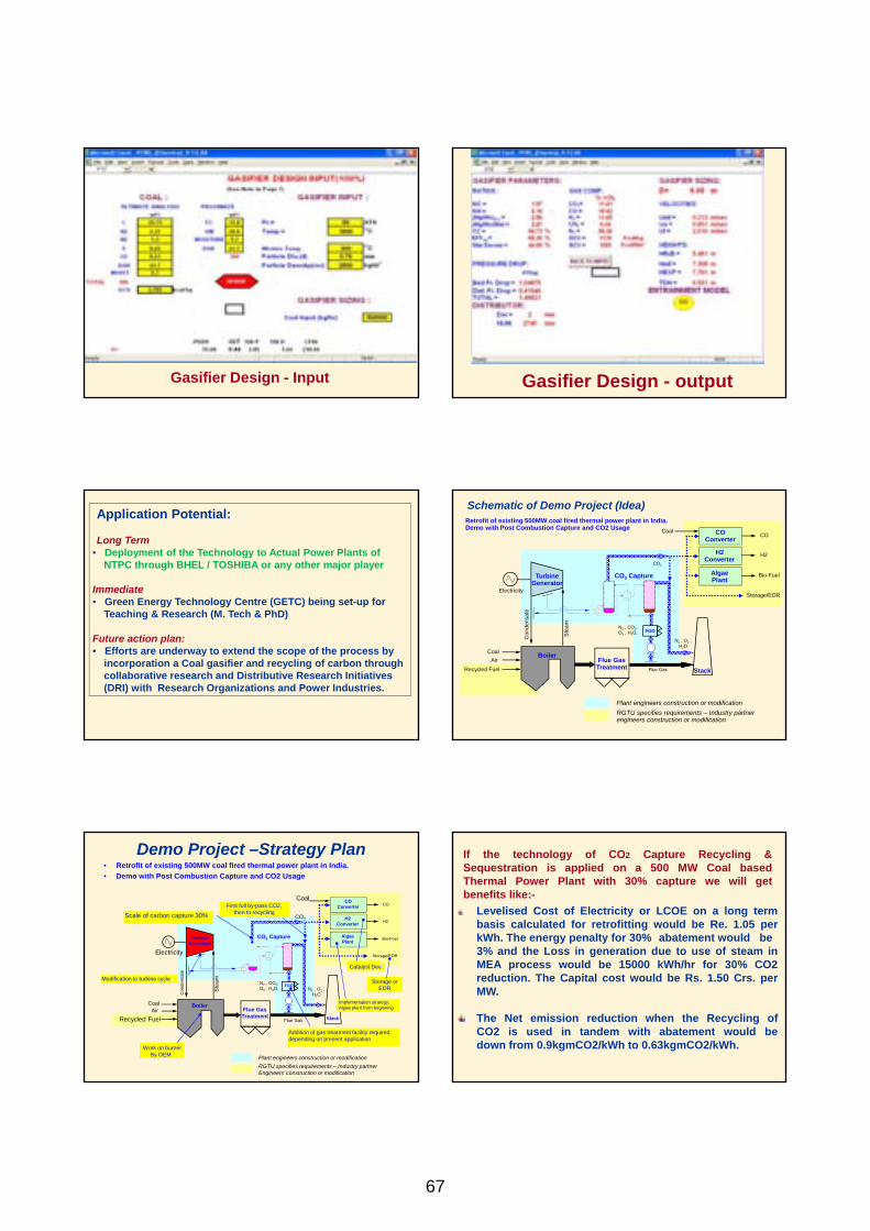
Gasifier Design - Input
Gasifier Design - output
Application Potential: Long Term
• Deployment of the Technology to Actual Power Plants of NTPC through BHEL / TOSHIBA or any other major player Immediate • Green Energy Technology Centre (GETC) being set-up for Teaching & Research (M. Tech & PhD) Future action plan: • Efforts are underway to extend the scope of the process by incorporation a Coal gasifier and recycling of carbon through collaborative research and Distributive Research Initiatives (DRI) with Research Organizations and Power Industries.
Schematic of Demo Project (Idea)
Coal Air
Boiler
Stack
CO2 Capture
Flue Gas
Ste
am
Con
dens
ate
Turbine Generator
CO2
Electricity
Flue Gas Treatment
N2 , O2 , H2O
N2 , CO2, O2 , H2O,
CO Converter
Coal
Plant engineers construction or modification RGTU specifies requirements – Industry partner engineers construction or modification
Retrofit of existing 500MW coal fired thermal power plant in India. Demo with Post Combustion Capture and CO2 Usage
Algae Plant
Bio-Fuel
Recycled Fuel
H2 Converter
CO
FGD
H2
Storage/EOR
Demo Project –Strategy Plan • Retrofit of existing 500MW coal fired thermal power plant in India. • Demo with Post Combustion Capture and CO2 Usage
Coal Air
Boiler
Stack
CO2 Capture
Flue Gas
Ste
am
Con
dens
ate
Turbine Generator
CO2
Electricity
Flue Gas Treatment
N2 , O2 , H2O
N2 , CO2, O2 , H2O,
CO Converter
Coal
Plant engineers construction or modification RGTU specifies requirements – Industry partner Engineers’ construction or modification
Algae Plant
Bio-Fuel
Recycled Fuel
H2 Converter
CO
FGD
H2
Storage/EOR
Modification to turbine cycle
Scale of carbon capture 30%
First full by-pass CO2, then to recycling
Implementation strategy: Algae plant from beginning
Catalyst Dev.
Addition of gas treatment facility required, depending on present application
Work on burner By OEM
Storage or EOR
If the technology of CO2 Capture Recycling & Sequestration is applied on a 500 MW Coal based Thermal Power Plant with 30% capture we will get benefits like:- Levelised Cost of Electricity or LCOE on a long term
basis calculated for retrofitting would be Re. 1.05 per kWh. The energy penalty for 30% abatement would be 3% and the Loss in generation due to use of steam in MEA process would be 15000 kWh/hr for 30% CO2 reduction. The Capital cost would be Rs. 1.50 Crs. per MW.
The Net emission reduction when the Recycling of CO2 is used in tandem with abatement would be down from 0.9kgmCO2/kWh to 0.63kgmCO2/kWh.
67
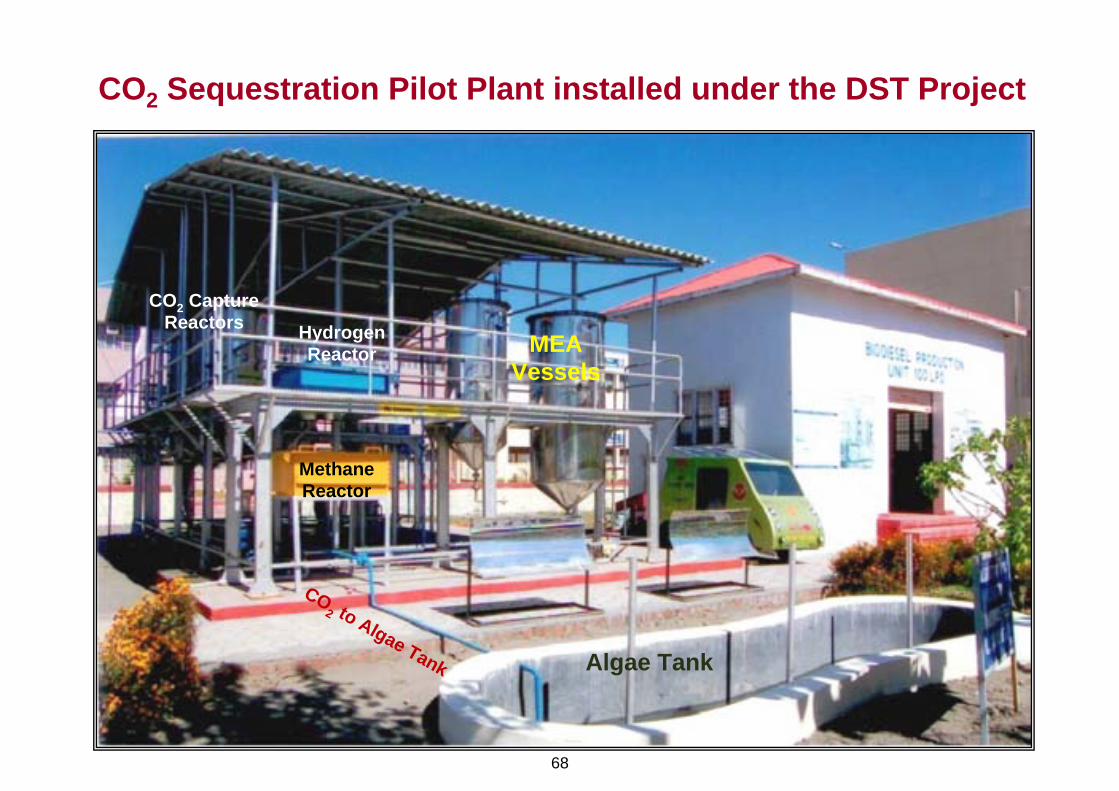
CO2 Sequestration Pilot Plant installed under the DST Project
Algae Tank
MethaneReactor
HydrogenReactor MEA
Vessels
CO2 CaptureReactors
CO2 to Algae Tank
68