precast concrete never looked so good! · of the aforementioned types of centrifugal pumps,...
TRANSCRIPT

PRECAST CONCRETENever Looked So Good!
Delivering More.
P E R F O R M A N C E | Q U A L I T Y | S E R V I C E | T R U S T

PERFORMANCE | QUALITY | SERVICE | TRUST
A pump is the heart of any pumping system. The principles of pumping liquid have been known since the time of the early Egyptians. They have raised water for irrigation from the Nile River to the plains. A working definition of a pump for our time might be:
A PUMP IS A DEVICE THAT ADDS ENERGY TO A LIQUID IN ORDER TO
MOVE IT FROM ONE POINT TO ANOTHER
There are, of course, many kinds of pumps in use. Their horsepower may be as little as a friction of the horsepower or as large as several thousand horsepower. Pressure ranges from ounces per square inch to many thousand PSI. Pumps can be driven by electric motors, gas or diesel engines, steam engines or back on the farm, by hand.
There are many types of centrifugal pumps: volute, diffuser, regenerative-turbine, vertical-turbine, mixed-flow (propeller) and self-priming. Of the aforementioned types of centrifugal pumps, National Pump Company specializes in the manufacture of vertical turbine pumps and Packaged Pump Stations. This enables National Pump to offer its distributors and end-users a complete pumping solution.
Introduction
PERFORMANCE | QUALITY | SERVICE | TRUST
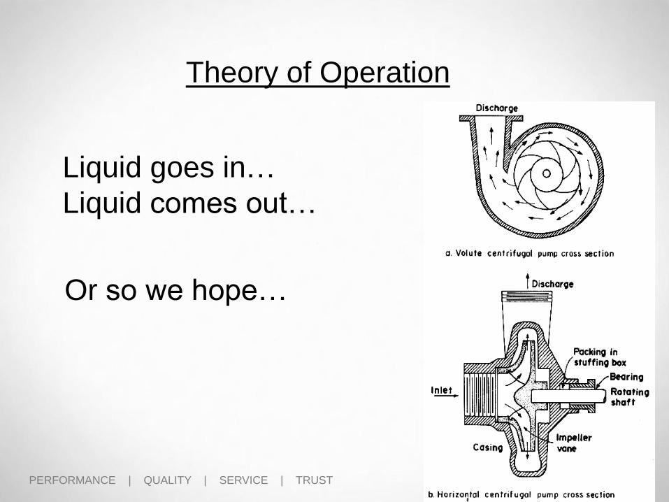
Theory of Operation
Liquid goes in…
Liquid comes out…
Or so we hope…

PERFORMANCE | QUALITY | SERVICE | TRUST
Centrifugal Pump Basics
• The impeller is only part of the hydraulic design. Work is useful only when the product being pumped is controlled.
• The Volute/Bowl is the other part of the hydraulic design which transforms the velocity of the liquid into pressure and controls the product being pumped.

PERFORMANCE | QUALITY | SERVICE | TRUST
A - Impeller Suction
B – Impeller Vane
C – Bowl Diffusers
D – Bowl Discharge
Vertical Turbine Basics

PERFORMANCE | QUALITY | SERVICE | TRUST
Discharge Case
Liquid InletImpeller
Impeller Vane
Discharge Bowl w/ Diffuser Vanes
Bowl Bearing
Vertical Turbine Pump Basics

PERFORMANCE | QUALITY | SERVICE | TRUST
Vertical Turbine Basics
• The impeller vanes and Bowl Diffuser vanes are matched for optimum pump performance.
• The diffuser straightens the flow from the impeller into the next impeller to limit the amount of flow pre-rotation and to maximize pump efficiency.

PERFORMANCE | QUALITY | SERVICE | TRUSTSecond Edition 2/4/11
Performance Curve
HP= 18
NPSHr= 12’
FLOW= 1000
HEAD= 62’
Note: A pump
only knows to
follow its
curve

PERFORMANCE | QUALITY | SERVICE | TRUST
Proper Pump Selection
Optimum Range = 50 – 120% of BEP
PERFORMANCE | QUALITY | SERVICE | TRUST
Applying National Pumps to your System ?
1. Determining Pump Application and
System Requirements
2. Pump Selection and Sizing
3. Pump Repair or Replacement

PERFORMANCE | QUALITY | SERVICE | TRUST
Pump and System Requirements
MARKET OFTEN DETERMINES PUMP REQUIREMENTS
• Agricultural – Crops - flood, spray
• Municipal – Water supply & distribution, water treatment, wastewater
collection, desalination
• Municipal Well - Municipal, deep well > 40’ w/ service capability
(drillers/installers)
• Industrial - Mining, power, dewatering
• Power - Generating Power Plants
• Commercial / HVAC - Buildings and institutions for the occupancy of
people (HVAC)
• OEM’s - Process cooling/heating, pump packagers, etc.
• Golf / Turf - Commercial turf, golf
• Oil and Gas - Oil production, refining, pipeline, gas processing, fuel oil
• Water Systems - Residential, snow making, flood control, ground
water development

PERFORMANCE | QUALITY | SERVICE | TRUST
Pump System

PERFORMANCE | QUALITY | SERVICE | TRUST
Determining Needs (INPUTS)• Flow and Head
• Efficiency (Target or HI Standard)
• Well, Wet Well, or Suction Can?
• Water or Oil Lube (Water Inj.)
• Setting Depth ( Elevations )
• High and Low Water Levels
• Suction Pressure
• NPSHa (calculated)
• Application – Raw Water, Booster, High Service
• Motor Controls (ATL, PWS, RVSS, VFD)
• Motor Requirements (Encl., Amb. Temp.)
Pump and System Requirements

PERFORMANCE | QUALITY | SERVICE | TRUST
• Filled out pump Data Sheet
• Basic information needed to
quote – Standard Pump or
Bid & Spec. Project
• Proper information will:
speed-up quote Time
increase quote accuracy
Pump and System Requirements

PERFORMANCE | QUALITY | SERVICE | TRUST
• Pump Requirement Data
Form
• ISO 9001 Document
Pump and System Requirements

PERFORMANCE | QUALITY | SERVICE | TRUST
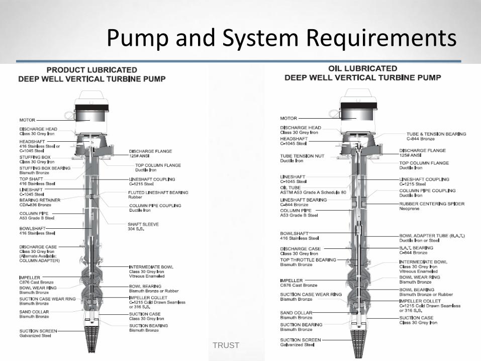
• Oil lubrication is recommended after 100 ft of setting (if not using a pre-lube system)
• Oil Lube/enclosed Lineshaft w/an electrical solenoid for automatic or manual valve for oil line lubrication
• Water Lube/ Open line shaft using the water as the lubrication for the bearings (also known as product lubricated)
Oil Lubrication vs. Water Lube
PERFORMANCE | QUALITY | SERVICE | TRUST
Pump and System Requirements

PERFORMANCE | QUALITY | SERVICE | TRUST
Pump and System Requirements

PERFORMANCE | QUALITY | SERVICE | TRUST
Determining Needs (OUTPUTS) Total Dynamic Head
• Elevation Differences (feet)
• Pressure Requirements (psig)
• Column Pipe Friction Loses
• Discharge Head Friction Losses
Pump Selection / # of stages
Pump Total BHP
• Pump (Bowl) Efficiency and BHP (calc.)
• Shaft HP
Pump and System Requirements
PERFORMANCE | QUALITY | SERVICE | TRUST
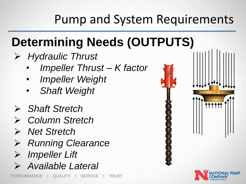
Determining Needs (OUTPUTS) Hydraulic Thrust
• Impeller Thrust – K factor
• Impeller Weight
• Shaft Weight
Shaft Stretch
Column Stretch
Net Stretch
Running Clearance
Impeller Lift
Available Lateral
Pump and System Requirements

PERFORMANCE | QUALITY | SERVICE | TRUST
Pump Selection - Web Version

PERFORMANCE | QUALITY | SERVICE | TRUST
Pump System Example
30’
50’150’
120 psig
• 1,000 GPM

PERFORMANCE | QUALITY | SERVICE | TRUST
Sizing Example
• Total Dynamic Head
= (50’ + 30’) + (120 psig. x 2.31) + (2.97 x 150’) + 0.47= 204.92 ( 205’ TDH )
100
Static W.L. Disch. El.
Disch. Press.
Col. Friction
Col. Length
Disch. Head Frict. Losses

PERFORMANCE | QUALITY | SERVICE | TRUST
Sizing Example
• 1,000 @ 209’
• 8.34” Impeller
• 83.6% Eff.
• 62.9 BHP Design
• 69.9 BHP Max.

PERFORMANCE | QUALITY | SERVICE | TRUST
Sizing Example
• J11HC….4 stages trimmed to 8.34”
• Eff. = 83.6%
• HP = (1000 x 209) = 63.1 HP
(3960 x 0.836)
• SHAFT HP of 1.5” shaft = (1.14 x 150) = 1.71 HP (page 36)
100
• BHP = 63.1 (BHP) + 1.17 (SHAFT HP) = 64.3 at design point
• BHP = 69.9 + 1.17 = 71.07 at run-out
• Select a 75 HP motor for NON-OVERLOADING or VFD OPERATION

PERFORMANCE | QUALITY | SERVICE | TRUST
Sizing Examples
Down-Thrust Calculations
• Imp./Bowl Thrust = 7.9 (K factor) x 209 = 1650 lbs. (page 34) (K factor is Thrust per foot of TDH)
• Total Down Thrust = 1650 + (18.5x4) + (6.01 x 150) = 2625 #Imp. Thrust + Imp. Wt. x # Imp + 1-1/2” Shaft Wt x Setting
(page 34) (Page 37)

PERFORMANCE | QUALITY | SERVICE | TRUST
Sizing Examples
Shaft / Column Stretch & Bowl Lateral
• Shaft Elongation = .062 / 100 x 150 (Setting) =.093” (page 42…2600 # with 1-1/2” shaft)
• Column Elongation = .007 / 100 x 1.3 x 150 (Setting) = .01365” (page 43…1600#...8” column)
• Net Stretch = .093” (Shaft Stretch) - .01365” (Column Stretch) = .07935”
• Bowl Lateral – J11 Standard Lateral is 1” / 1-1/4” max. (page 34)
• Running Clearance – Est. = .19” (3/16”)
• Impeller Lift = .07935” (Net Stretch) + .19 (Running Clearance) = .26935”
• Available Lateral = 1.0” (Standard Bowl lateral) – 0.26935” (Impeller Lift) = .7306”
PERFORMANCE | QUALITY | SERVICE | TRUST
Q & A

PERFORMANCE | QUALITY | SERVICE | TRUST
Delivering More.
P E R F O R M A N C E | Q U A L I T Y | S E R V I C E | T R U S T
REPAIR OR REPLACE ?

PERFORMANCE | QUALITY | SERVICE | TRUST
Maintaining Pump Efficiency
“It is considered good practice to replace or repair wearing rings when the nominal clearance has doubled. The presence of abrasive solids in the liquid pumped may be expected to increase wearing-ring clearance rapidly.”
“Pump Handbook,” Karassik et al, 1986, Second Edition, p. 2.204

PERFORMANCE | QUALITY | SERVICE | TRUST
Level 1 – Basic Repair
Level 2 – Extended Repair
Level 3 – Complete Overhaul
Repair or Replace

PERFORMANCE | QUALITY | SERVICE | TRUST
Level 1 – Basic Repair
• Slight Wear in and on the Wear Surfaces
- Bearings
- Shafting
- Bowl or Impeller Wear Rings
- Packing Boxes
- Seals
• Impeller Vein Wear and Deformities due to Solids
• Bowl Wear due to Solids
Repair or Replace
PERFORMANCE | QUALITY | SERVICE | TRUST
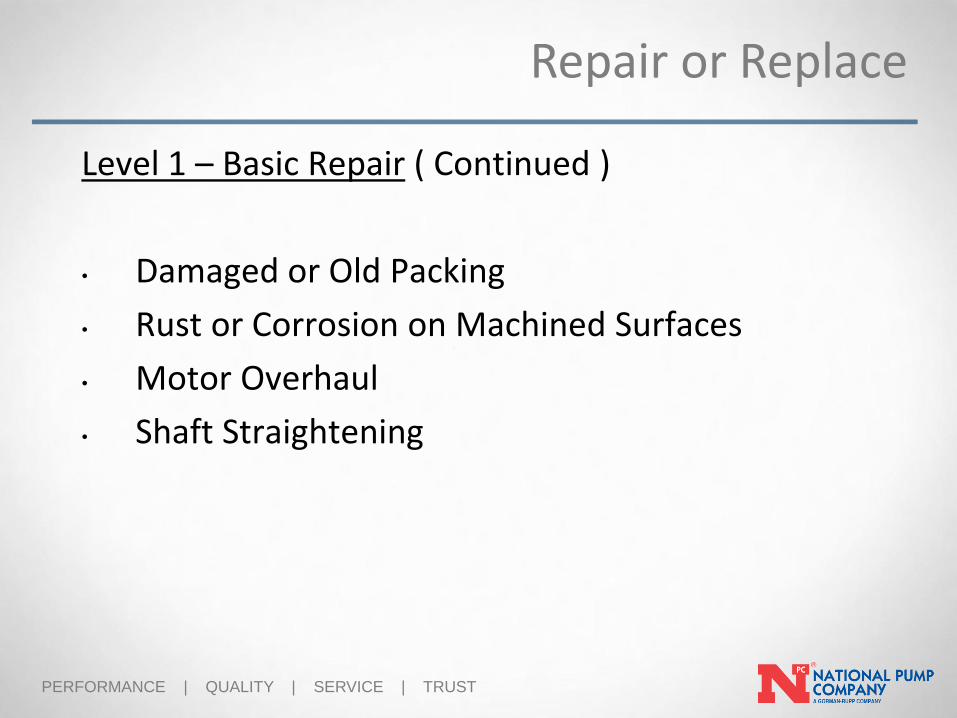
Level 1 – Basic Repair ( Continued )
• Damaged or Old Packing
• Rust or Corrosion on Machined Surfaces
• Motor Overhaul
• Shaft Straightening
Repair or Replace

PERFORMANCE | QUALITY | SERVICE | TRUST
Level 2 – Extended Repair
• Replacing Bowl Assembly ( Re-Bowl )
• Replacing Shafts
• Replacing Packing Boxes or Seals
• Replacement Minor Components that cannot be Repaired
Repair or Replace

PERFORMANCE | QUALITY | SERVICE | TRUST
Level 3 – Complete Overhaul
• Replacement of Major Components
• Complete Pump Replacement
Repair or Replace
PERFORMANCE | QUALITY | SERVICE | TRUST
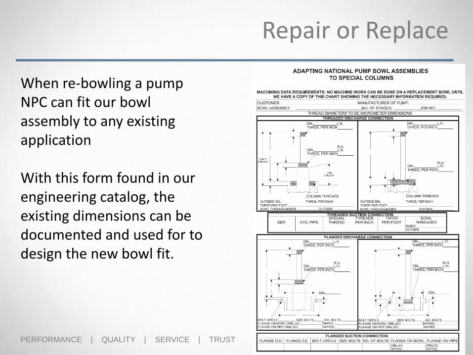
When re-bowling a pump NPC can fit our bowl assembly to any existing application
With this form found in our engineering catalog, the existing dimensions can be documented and used for to design the new bowl fit.
Repair or Replace

PERFORMANCE | QUALITY | SERVICE | TRUST
Repair or Replace
PERFORMANCE | QUALITY | SERVICE | TRUST
Repair or Replace

PERFORMANCE | QUALITY | SERVICE | TRUST
Repair or Replace

PERFORMANCE | QUALITY | SERVICE | TRUST
Repair or Replace

PERFORMANCE | QUALITY | SERVICE | TRUST
Q & A
Repair or Replace
PERFORMANCE | QUALITY | SERVICE | TRUST
Delivering More.
P E R F O R M A N C E | Q U A L I T Y | S E R V I C E | T R U S T
CENTRIFUGAL PUMP
PRINCIPALS

PERFORMANCE | QUALITY | SERVICE | TRUST
A few important pump principals to
understand:
1. Affinity Laws
2. Bernoulli’s Theorem
3. N.P.S.H. - Otherwise known as “Net Positive
Suction Head”

PERFORMANCE | QUALITY | SERVICE | TRUST
Affinity Laws

PERFORMANCE | QUALITY | SERVICE | TRUST
Performance depends on 4 items:
1. Pump Hydraulic Design (impeller type & design)
2. Impeller Diameter 3. Impeller Speed (RPM)
4. Pump Efficiency
En
clo
se
dS
oli
ds H
an
dli
ng
Op
en
The Affinity Laws
The affinity laws accurately predict the
effect of changing the speed and
impeller diameter of a centrifugal pump

PERFORMANCE | QUALITY | SERVICE | TRUST
• Change in Speed is directly proportional to change in Flow.
• 2 x RPM …..2 x FLOW
• 2 x RPM…...4 x HEAD
• 2 x RPM……8 x BHP
RPM 1 = Flow 1 3600 = Flow 1 Flow 1 = 2000 GPM
RPM 2 Flow 2 1800 1000 Double the Speed…Flow x 2
RPM 1 = Head 1 3600 = Head 1 Head 1 = 400 Feet
RPM 2 Head 2 1800 100 Double the Speed…..Head x 4
RPM 1 = BHP 1 3600 = BHP 1 BHP 1 = 252 HP
RPM 2 BHP 2 1800 31.5 Double the Speed…..BHP x 8
The Affinity Laws
2
3
2
3

PERFORMANCE | QUALITY | SERVICE | TRUST
• Change in Impeller Diameter is directly proportional to
change in Flow.
• 2 x IMP DIA. …..2 x FLOW
• 2 x IMP DIA. …...4 x HEAD
• 2 x IMP DIA. ……8 x BHP
DIA 1 = Flow 1 20” = Flow 1 Flow 1 = 2000 GPM
DIA 2 Flow 2 10” 1000 Flow varies proportionally with Imp Dia.
DIA 1 = Head 1 20” = Head 1 Head 1 = 400 Feet
DIA 2 Head 2 10” 100 Double the Imp. Dia.…..Head x 4
DIA 1 = BHP 1 20” = BHP 1 BHP 1 = 252 HP
DIA 2 BHP 2 10” 31.5 Double the Imp. Dia. …..BHP x 8
The Affinity Laws
2
3
2
3
DIA 1
DIA 2

PERFORMANCE | QUALITY | SERVICE | TRUST
AFFINITY LAWS
RPM1 = Q1 = H1 = BHP1RPM2 = Q2 = H2 = BHP2
Therefore, IF….
RPM increases x 2Flow increases x 2Head increases SquaredBHP increases Cubed
2 3

PERFORMANCE | QUALITY | SERVICE | TRUST
AFFINITY LAWS
1800 rpm900 rpm
1800 rpm = x 2 for Flow….. X 4 for Head….x 8 for BHP900 rpm
2.2 BHP18.0 BHP

PERFORMANCE | QUALITY | SERVICE | TRUST
Bernoulli’s Theory

PERFORMANCE | QUALITY | SERVICE | TRUST
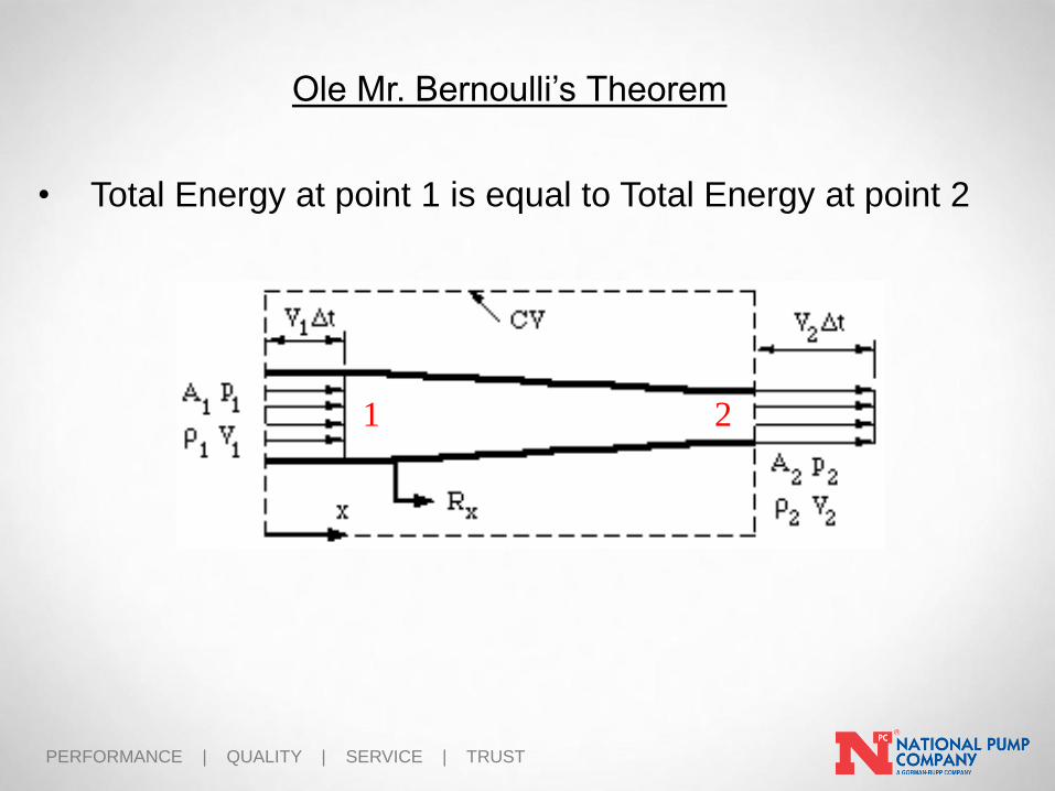
Ole Mr. Bernoulli’s Theorem
• Total energy in a fluid is the sum of its VELOCITY energy
and its PRESSURE energy.
Total Energy = VELOCITY + PRESSURE
• Centrifugal pumps increase Total Energy by first adding
VELOCITY Energy and then transforming it to
PRESSURE Energy.
PERFORMANCE | QUALITY | SERVICE | TRUST
Ole Mr. Bernoulli’s Theorem
1 2
• Total Energy at point 1 is equal to Total Energy at point 2

PERFORMANCE | QUALITY | SERVICE | TRUSTSecond Edition 2/4/11
Bernoulli’s EquationEnergy at Point 2 = Point 1 + Energy added by Pump
1
2
PERFORMANCE | QUALITY | SERVICE | TRUST
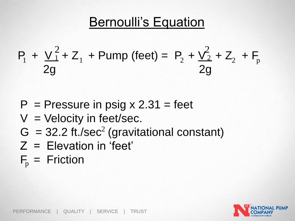
Bernoulli’s Equation
P + V + Z + Pump (feet) = P + V + Z + F
2g 2g
2 21 2211 2
P = Pressure in psig x 2.31 = feet
V = Velocity in feet/sec.
G = 32.2 ft./sec (gravitational constant)
Z = Elevation in ‘feet’
F = Friction
2
p
p

PERFORMANCE | QUALITY | SERVICE | TRUST
Bernoulli’s Equation - Quiz
Pick a flow and calculate!
400 GPM(page 41)
5.12 28.22 feet
28.22 feet
28.22 feet23.15.12
Vel.=18.16 ft/sec
Vel.=18.16 ft/sec
Vel.=10.21 ft/sec 1.62 26.6
26.60 ft / 2.31 = 11.5 PSI
10 PSI 10 PSI

PERFORMANCE | QUALITY | SERVICE | TRUST
Does Bernoulli’s equation apply here?
Bernoulli’s Equation - Quiz

PERFORMANCE | QUALITY | SERVICE | TRUST
Bernoulli’s Equation - Quiz
• Liquid leaves Impeller (A) and is collected in the area just before the diffuser Vanes (B)
• Diffuser Vanes (C) are designed to slowly increase in area and convert the high velocity to pressure energy
• The vanes also turn the flow to an axial direction providing a smooth flow into the next stage impeller.

PERFORMANCE | QUALITY | SERVICE | TRUST
Bernoulli’s Equation
Note: As liquid
enters the
impeller…velocity
increases….and
therefore the
pressure drops

PERFORMANCE | QUALITY | SERVICE | TRUST
NPSH

PERFORMANCE | QUALITY | SERVICE | TRUST
NPSH
Cavitation - a common problem in pumps and control valves -
causing serious wear and tear and damage. Under the wrong
condition, cavitation will reduce the components life time
dramatically.
What is Cavitation?
Cavitation may occur when the local static pressure in a fluid reach
a level below the vapor pressure of the liquid at the actual
temperature.
According to the Bernoulli Equation this may happen when the
fluid accelerates in a control valve or around a pump impeller.
The vaporization itself does not cause the damage - the damage
happens when the vapor almost immediately collapses after
evaporation when the velocity is decreased and pressure increased.

PERFORMANCE | QUALITY | SERVICE | TRUST
The Dreaded NPSH
Velocity Increases
…Pressure Drops

PERFORMANCE | QUALITY | SERVICE | TRUST
The Dreaded NPSH
Area of Vapor Bubble
Collapse

PERFORMANCE | QUALITY | SERVICE | TRUST
Cavitation Damage

PERFORMANCE | QUALITY | SERVICE | TRUST
N.P.S.H. required
• NPSHr is derived from pump testing and is shown on
the performance curve
• NPSHr increases and become unpredictable on right
side of curve….which causes loss of performance

PERFORMANCE | QUALITY | SERVICE | TRUST
N.P.S.H. required
NPSHa > NPSHr
“NPSH available” must be a
minimum of 3 feet greater than
“NPSH required” to insure trouble-
free pump service.
PERFORMANCE | QUALITY | SERVICE | TRUST
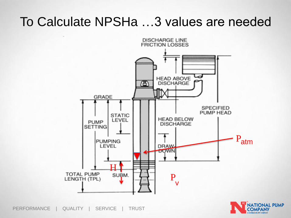
To Calculate NPSHa …3 values are needed
atmP
HP
v

PERFORMANCE | QUALITY | SERVICE | TRUST
N.P.S.H. available
NPSHa is calculated as:
NPSHa = P + H - P
NPSHa – feet
P (vapor pressure) - psia x 2.31 = feet
H (height of fluid above impeller) - feet
P (vapor pressure of fluid) - psia x 2.31 = feet
atm v
v
atm
PERFORMANCE | QUALITY | SERVICE | TRUST
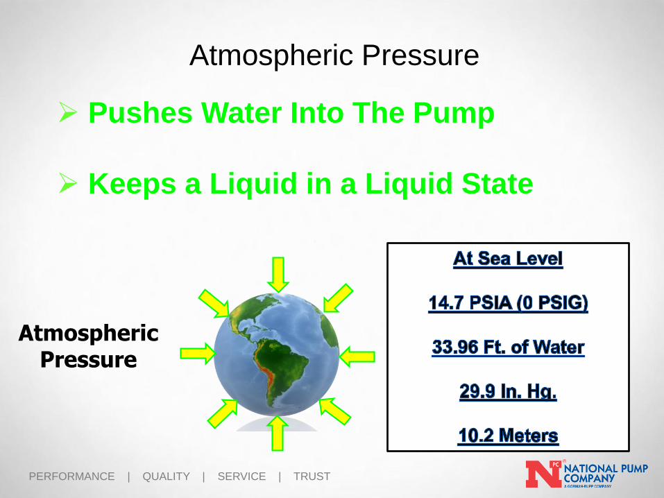
Pushes Water Into The Pump
Keeps a Liquid in a Liquid State
AtmosphericPressure
Atmospheric Pressure

PERFORMANCE | QUALITY | SERVICE | TRUST
Atmospheric Pressure
PERFORMANCE | QUALITY | SERVICE | TRUST
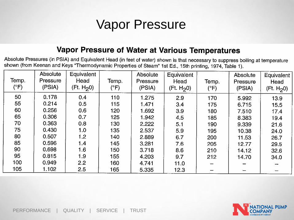
Vapor Pressure

PERFORMANCE | QUALITY | SERVICE | TRUST
Delivering More.
P E R F O R M A N C E | Q U A L I T Y | S E R V I C E | T R U S T
QUESTIONS ?