precision actuators gearheads gearing components...c. walt musser patented strain wave gearing in...
TRANSCRIPT
Precision Actuators • Gearheads • Gearing Components
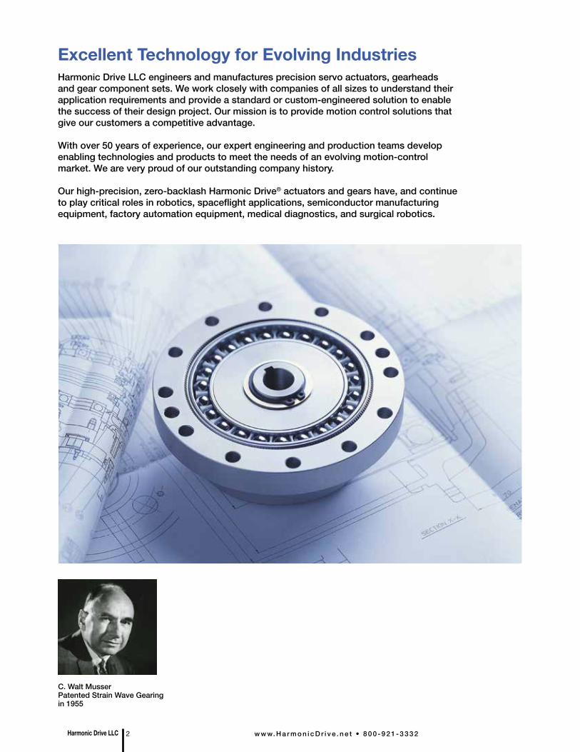
C. Walt MusserPatented Strain Wave Gearing in 1955
Excellent Technology for Evolving IndustriesHarmonic Drive LLC engineers and manufactures precision servo actuators, gearheads and gear component sets. We work closely with companies of all sizes to understand their application requirements and provide a standard or custom-engineered solution to enable the success of their design project. Our mission is to provide motion control solutions that give our customers a competitive advantage.
With over 50 years of experience, our expert engineering and production teams develop enabling technologies and products to meet the needs of an evolving motion-control market. We are very proud of our outstanding company history.
Our high-precision, zero-backlash Harmonic Drive® actuators and gears have, and continue to play critical roles in robotics, spaceflight applications, semiconductor manufacturing equipment, factory automation equipment, medical diagnostics, and surgical robotics.
Harmonic Drive LLC 2 w w w. H a r m o n i c D r i v e . n e t • 8 0 0 - 9 2 1 - 3 3 3 2
Features• Zero backlash• High positioning accuracy• High repeatability
• Compactness• Light weight • High reduction ratio
Harmonic Drive® High-Precision Strain Wave Gearing
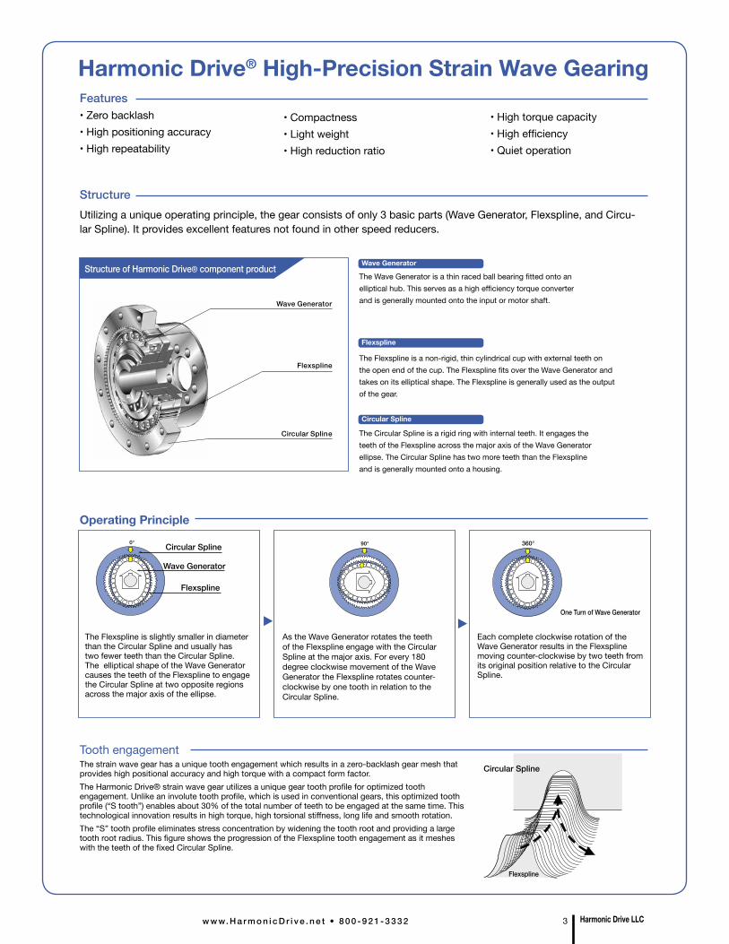
StructureUtilizing a unique operating principle, the gear consists of only 3 basic parts (Wave Generator, Flexspline, and Circu-lar Spline). It provides excellent features not found in other speed reducers.
Wave Generator
Flexspline
Circular Spline
The Wave Generator is a thin raced ball bearing fitted onto anelliptical hub. This serves as a high efficiency torque converterand is generally mounted onto the input or motor shaft.
The Flexspline is a non-rigid, thin cylindrical cup with external teeth on the open end of the cup. The Flexspline fits over the Wave Generator and takes on its elliptical shape. The Flexspline is generally used as the output of the gear.
The Circular Spline is a rigid ring with internal teeth. It engages theteeth of the Flexspline across the major axis of the Wave Generatorellipse. The Circular Spline has two more teeth than the Flexspline and is generally mounted onto a housing.
Structure of Harmonic Drive® component product
Circular Spline
Flexspline
Tooth engagementThe strain wave gear has a unique tooth engagement which results in a zero-backlash gear mesh that provides high positional accuracy and high torque with a compact form factor.The Harmonic Drive® strain wave gear utilizes a unique gear tooth profile for optimized tooth engagement. Unlike an involute tooth profile, which is used in conventional gears, this optimized tooth profile (“S tooth”) enables about 30% of the total number of teeth to be engaged at the same time. This technological innovation results in high torque, high torsional stiffness, long life and smooth rotation.The “S” tooth profile eliminates stress concentration by widening the tooth root and providing a large tooth root radius. This figure shows the progression of the Flexspline tooth engagement as it meshes with the teeth of the fixed Circular Spline.
Operating Principle
The Flexspline is slightly smaller in diameter than the Circular Spline and usually has two fewer teeth than the Circular Spline. The elliptical shape of the Wave Generator causes the teeth of the Flexspline to engage the Circular Spline at two opposite regions across the major axis of the ellipse.
As the Wave Generator rotates the teeth of the Flexspline engage with the Circular Spline at the major axis. For every 180 degree clockwise movement of the Wave Generator the Flexspline rotates counter-clockwise by one tooth in relation to the Circular Spline.
0° 90° 360°Circular Spline
Wave Generator
Flexspline
One Turn of Wave Generator
Each complete clockwise rotation of the Wave Generator results in the Flexspline moving counter-clockwise by two teeth from its original position relative to the Circular Spline.
• High torque capacity• High efficiency• Quiet operation
Flexspline
Wave Generator
Circular Spline
Harmonic Drive LLCw w w. H a r m o n i c D r i v e . n e t • 8 0 0 - 9 2 1 - 3 3 3 2 3
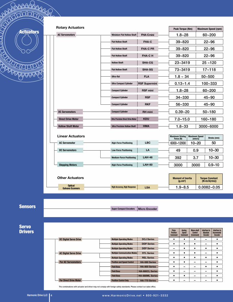
Rotary Actuators
Linear Actuators
Other Actuators
KDU
RH mini
LBC
LA
LAH-46
LAH-80
For Direct Drive Motor
DC Digital Servo Drive
AC Digital Servo Drive
Ultra Precision Direct Drive MotorDirect Drive Motor
Compact Cylinder DC Servomotors
AC Servomotors
AC Servomotor
DC Servomotors
Stepping Motors
High-Force Positioning
Low-Force Positioning
Medium-Force Positioning
High-Force Positioning
0.39~20 50~180
1.8~28
39~820
39~820
39~820
23~3419
73~3419
1.8 ~ 34
0.13~1.4
1.8~28
34~330
56~330
60~200
22~96
22~96
22~96
25 ~120
17~118
50~500
100~333
60~200
45~90
45~90
6000~12000
49
392
3000
10~20
0.9
3.7
3000
50
10~30
10~30
0.9~10
The combinations with actuator and driver may not comply with foreign safety standards. Please contact our sales office.
Maximum Driving Force (N)
Maximum Speed(mm/s) Stroke (mm)
Peak Torque (Nm) Maximum Speed (rpm)
Interface to Absolute Encoder
Interface toIncremental
Encoder
Pulse Position
Command
••–•••••••
••••••––•–
•••••–––––
––•–•–•–––
••••••••••
Analog Speed
Command
Mono-shaft Control
(Command)
7.0~15.0 160~180HMAUltra Precision Hollow ShaftHollow Shaft Motor 1.8~33 3000~6000
FHA-Cmini
FHA-C
FHA-C PR
FHA-C H
SHA-CG
SHA-SG
FLA
RSF Supermini
RSF mini
RSF
RKF
Miniature Flat Hollow Shaft
Flat Hollow Shaft
Flat Hollow Shaft
Flat Hollow Shaft
Hollow Shaft
Flat Hollow Shaft
Ultra-flat
Ultra Compact Cylinder
Compact Cylinder
Compact Cylinder
Compact Cylinder
Position and Speed Control HA-680 Series
HA-680ML Series
HA-680CL Series
Position Control Only HA-770 Series
Multiple Communication Modes RTL Series
Multiple Operating Modes REL Series
Multiple Operating Modes DCJ Series
Multiple Operating Modes DDP Series
Multiple Operating Modes DEP Series
For AC ServomotorsHA-800 SeriesField Boss
Field Boss
Field Boss
Super-Compact Encoders Micro Encoder
OpticalGalvano Scanners 1.9~8.5 0.0082~0.05
Moment of Inertia(g.cm2)
Torque Constant (N•m/A(rms))
LSAHigh Accuracy, High Response
Actuators
Servo Drivers
Sensors
w w w. H a r m o n i c D r i v e . n e t • 8 0 0 - 9 2 1 - 3 3 3 2Harmonic Drive LLC 4
Rotary Actuators
Linear Actuators
Other Actuators
KDU
RH mini
LBC
LA
LAH-46
LAH-80
For Direct Drive Motor
DC Digital Servo Drive
AC Digital Servo Drive
Ultra Precision Direct Drive MotorDirect Drive Motor
Compact Cylinder DC Servomotors
AC Servomotors
AC Servomotor
DC Servomotors
Stepping Motors
High-Force Positioning
Low-Force Positioning
Medium-Force Positioning
High-Force Positioning
0.39~20 50~180
1.8~28
39~820
39~820
39~820
23~3419
73~3419
1.8 ~ 34
0.13~1.4
1.8~28
34~330
56~330
60~200
22~96
22~96
22~96
25 ~120
17~118
50~500
100~333
60~200
45~90
45~90
6000~12000
49
392
3000
10~20
0.9
3.7
3000
50
10~30
10~30
0.9~10
The combinations with actuator and driver may not comply with foreign safety standards. Please contact our sales office.
Maximum Driving Force (N)
Maximum Speed(mm/s) Stroke (mm)
Peak Torque (Nm) Maximum Speed (rpm)
Interface to Absolute Encoder
Interface toIncremental
Encoder
Pulse Position
Command
••–•••••••
••••••––•–
•••••–––––
––•–•–•–––
••••••••••
Analog Speed
Command
Mono-shaft Control
(Command)
7.0~15.0 160~180HMAUltra Precision Hollow ShaftHollow Shaft Motor 1.8~33 3000~6000
FHA-Cmini
FHA-C
FHA-C PR
FHA-C H
SHA-CG
SHA-SG
FLA
RSF Supermini
RSF mini
RSF
RKF
Miniature Flat Hollow Shaft
Flat Hollow Shaft
Flat Hollow Shaft
Flat Hollow Shaft
Hollow Shaft
Flat Hollow Shaft
Ultra-flat
Ultra Compact Cylinder
Compact Cylinder
Compact Cylinder
Compact Cylinder
Position and Speed Control HA-680 Series
HA-680ML Series
HA-680CL Series
Position Control Only HA-770 Series
Multiple Communication Modes RTL Series
Multiple Operating Modes REL Series
Multiple Operating Modes DCJ Series
Multiple Operating Modes DDP Series
Multiple Operating Modes DEP Series
For AC ServomotorsHA-800 SeriesField Boss
Field Boss
Field Boss
Super-Compact Encoders Micro Encoder
OpticalGalvano Scanners 1.9~8.5 0.0082~0.05
Moment of Inertia(g.cm2)
Torque Constant (N•m/A(rms))
LSAHigh Accuracy, High Response
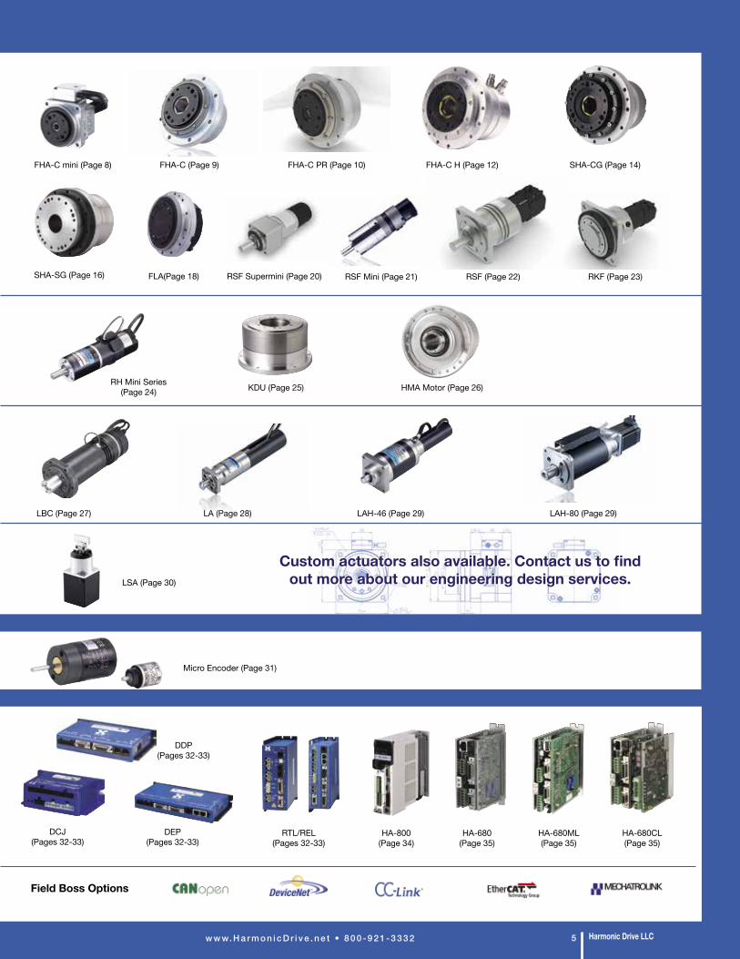
FHA-C mini (Page 8)
RSF Supermini (Page 20)FLA(Page 18) RSF Mini (Page 21)
LAH-46 (Page 29) LAH-80 (Page 29)
DCJ (Pages 32-33)
DDP (Pages 32-33)
DEP (Pages 32-33)
RTL/REL (Pages 32-33)
HA-800 (Page 34)
HA-680 (Page 35)
HA-680ML (Page 35)
HA-680CL (Page 35)
LSA (Page 30)
Micro Encoder (Page 31)
Field Boss Options
KDU (Page 25) HMA Motor (Page 26)
LBC (Page 27)
RH Mini Series (Page 24)
RKF (Page 23)SHA-SG (Page 16)
SHA-CG (Page 14)
Harmonic Drive LLCw w w. H a r m o n i c D r i v e . n e t • 8 0 0 - 9 2 1 - 3 3 3 2 5
FHA-C (Page 9) FHA-C PR (Page 10) FHA-C H (Page 12)
RSF (Page 22)
LA (Page 28)
Custom actuators also available. Contact us to find out more about our engineering design services.
Custom actuators also available. Contact us to find out more about our engineering design services.
18~260023~34005~320012~3940
5~400150~2200
9~752100~220
50:1~160:150:1~160:13:1~50:14:1~45:13:1~10:15:1~50:13:1~50:1
11:1
30~500030~500010~1500010~1500010~15000500~800030~7500500~2000
100~50023~340028~655
100:180:1~320:180:1~160:1
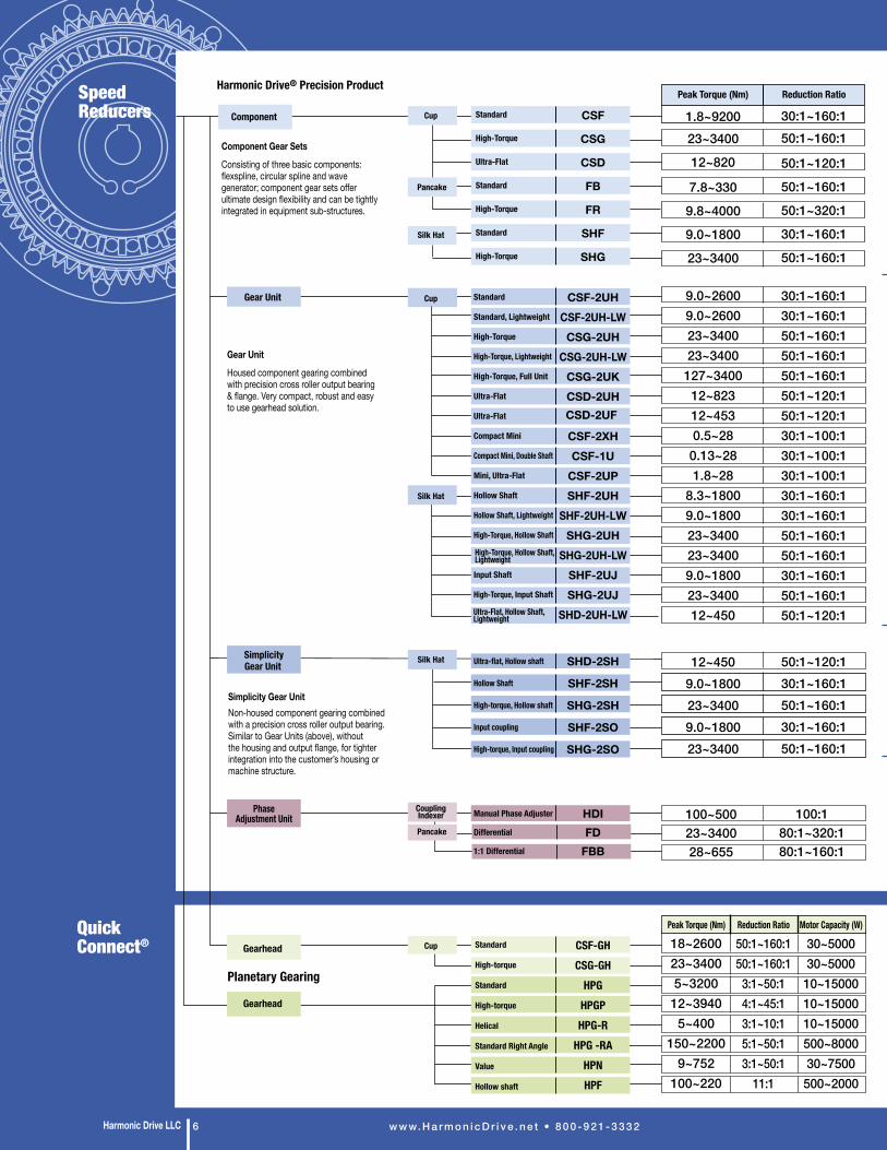
1.8~920023~3400
12~820
7.8~330
9.8~4000
9.0~1800
23~3400
30:1~160:150:1~160:1
50:1~120:1
50:1~160:1
50:1~320:1
30:1~160:1
50:1~160:1
9.0~26009.0~260023~340023~3400127~3400
12~82312~4530.5~280.13~281.8~28
8.3~18009.0~180023~340023~34009.0~180023~340012~450
30:1~160:130:1~160:150:1~160:150:1~160:150:1~160:150:1~120:150:1~120:130:1~100:130:1~100:130:1~100:130:1~160:130:1~160:150:1~160:150:1~160:130:1~160:150:1~160:150:1~120:1
Peak Torque (Nm) Reduction Ratio
Peak Torque (Nm) Reduction Ratio Motor Capacity (W)
Harmonic Drive® Precision Product
Planetary Gearing
Component
Gearhead
Gearhead
Gear Unit
PhaseAdjustment Unit
Cup
Pancake
Silk Hat
Cup
Silk Hat
CSF-GHCSG-GH
HPGHPGPHPG-R
HPG -RAHPNHPF
12~4509.0~180023~34009.0~180023~3400
50:1~120:130:1~160:150:1~160:130:1~160:150:1~160:1
SimplicityGear Unit SHD-2SH
SHF-2SH
SHG-2SH
SHF-2SO
SHG-2SO
Ultra-flat, Hollow shaft
Hollow Shaft
High-torque, Hollow shaft
Input coupling
High-torque, Input coupling
CSF
CSG
CSD
FB
FR
SHF
SHG
Standard
High-Torque
Ultra-Flat
Standard
High-Torque
Standard
High-Torque
CSF-2UHCSF-2UH-LWCSG-2UH
CSG-2UH-LWCSG-2UKCSD-2UHCSD-2UF CSF-2XHCSF-1U
CSF-2UPSHF-2UH
SHF-2UH-LWSHG-2UH
SHG-2UH-LWSHF-2UJSHG-2UJ
SHD-2UH-LW
Standard
Standard, Lightweight
High-Torque
High-Torque, Lightweight
High-Torque, Full Unit
Ultra-Flat
Ultra-Flat
Compact Mini
Compact Mini, Double Shaft
Mini, Ultra-Flat
Hollow Shaft
Hollow Shaft, Lightweight
High-Torque, Hollow Shaft
Input Shaft
High-Torque, Input Shaft
Standard
High-torque
Standard
High-torque
Helical
Standard Right Angle
Value
Hollow shaft
High-Torque, Hollow Shaft, Lightweight
Ultra-Flat, Hollow Shaft, Lightweight
Silk Hat
Coupling Indexer
Pancake
Cup
HDIFD
FBB
Manual Phase Adjuster
Differential
1:1 Differential
Gear Unit
Housed component gearing combined with precision cross roller output bearing & flange. Very compact, robust and easy to use gearhead solution.
Simplicity Gear UnitNon-housed component gearing combined with a precision cross roller output bearing. Similar to Gear Units (above), without the housing and output flange, for tighter integration into the customer’s housing or machine structure.
Component Gear Sets
Consisting of three basic components: flexspline, circular spline and wave generator; component gear sets offer ultimate design flexibility and can be tightly integrated in equipment sub-structures.
Speed Reducers
Quick Connect®
w w w. H a r m o n i c D r i v e . n e t • 8 0 0 - 9 2 1 - 3 3 3 2Harmonic Drive LLC 6
18~260023~34005~3200
12~39405~400
150~22009~752
100~220
50:1~160:150:1~160:13:1~50:14:1~45:13:1~10:15:1~50:13:1~50:1
11:1
30~500030~500010~1500010~1500010~15000500~800030~7500500~2000
100~50023~340028~655
100:180:1~320:180:1~160:1
1.8~920023~3400
12~820
7.8~330
9.8~4000
9.0~1800
23~3400
30:1~160:150:1~160:1
50:1~120:1
50:1~160:1
50:1~320:1
30:1~160:1
50:1~160:1
9.0~26009.0~260023~340023~3400
127~340012~82312~4530.5~28
0.13~281.8~28
8.3~18009.0~180023~340023~34009.0~180023~340012~450
30:1~160:130:1~160:150:1~160:150:1~160:150:1~160:150:1~120:150:1~120:130:1~100:130:1~100:130:1~100:130:1~160:130:1~160:150:1~160:150:1~160:130:1~160:150:1~160:150:1~120:1
Peak Torque (Nm) Reduction Ratio
Peak Torque (Nm) Reduction Ratio Motor Capacity (W)
Harmonic Drive® Precision Product
Planetary Gearing
Component
Gearhead
Gearhead
Gear Unit
PhaseAdjustment Unit
Cup
Pancake
Silk Hat
Cup
Silk Hat
CSF-GHCSG-GH
HPGHPGPHPG-R
HPG -RAHPNHPF
12~4509.0~180023~34009.0~180023~3400
50:1~120:130:1~160:150:1~160:130:1~160:150:1~160:1
SimplicityGear Unit SHD-2SH
SHF-2SH
SHG-2SH
SHF-2SO
SHG-2SO
Ultra-flat, Hollow shaft
Hollow Shaft
High-torque, Hollow shaft
Input coupling
High-torque, Input coupling
CSF
CSG
CSD
FB
FR
SHF
SHG
Standard
High-Torque
Ultra-Flat
Standard
High-Torque
Standard
High-Torque
CSF-2UHCSF-2UH-LWCSG-2UH
CSG-2UH-LWCSG-2UKCSD-2UHCSD-2UF CSF-2XHCSF-1U
CSF-2UPSHF-2UH
SHF-2UH-LWSHG-2UH
SHG-2UH-LWSHF-2UJSHG-2UJ
SHD-2UH-LW
Standard
Standard, Lightweight
High-Torque
High-Torque, Lightweight
High-Torque, Full Unit
Ultra-Flat
Ultra-Flat
Compact Mini
Compact Mini, Double Shaft
Mini, Ultra-Flat
Hollow Shaft
Hollow Shaft, Lightweight
High-Torque, Hollow Shaft
Input Shaft
High-Torque, Input Shaft
Standard
High-torque
Standard
High-torque
Helical
Standard Right Angle
Value
Hollow shaft
High-Torque, Hollow Shaft, Lightweight
Ultra-Flat, Hollow Shaft, Lightweight
Silk Hat
Coupling Indexer
Pancake
Cup
HDIFD
FBB
Manual Phase Adjuster
Differential
1:1 Differential
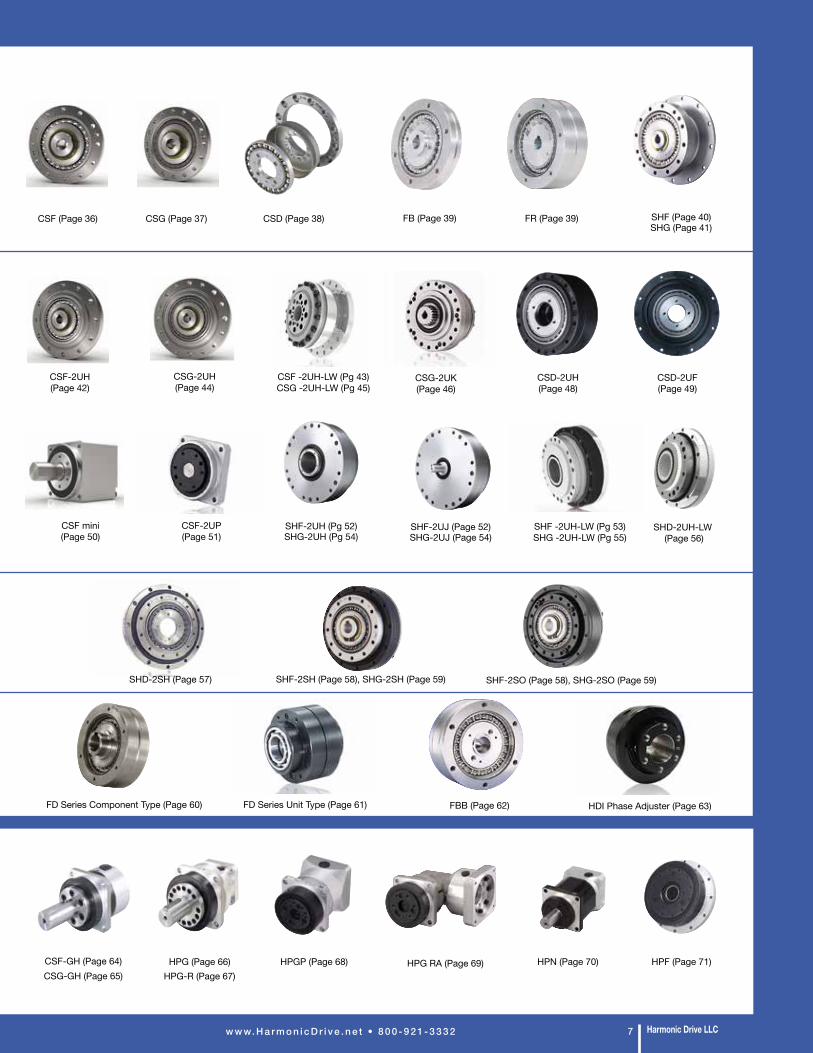
CSG (Page 37) CSD (Page 38)CSF (Page 36) SHF (Page 40) SHG (Page 41)
CSF-2UH (Page 42)
SHF-2UH (Pg 52) SHG-2UH (Pg 54)
FB (Page 39) FR (Page 39)
FBB (Page 62)
CSD-2UH (Page 48)
CSD-2UF (Page 49)
FD Series Component Type (Page 60)
Harmonic Drive LLCw w w. H a r m o n i c D r i v e . n e t • 8 0 0 - 9 2 1 - 3 3 3 2 7
CSG-2UH (Page 44)
CSG-2UK (Page 46)
CSF mini (Page 50)
CSF-2UP(Page 51)
SHD-2SH (Page 57) SHF-2SH (Page 58), SHG-2SH (Page 59) SHF-2SO (Page 58), SHG-2SO (Page 59)
FD Series Unit Type (Page 61)
CSF-GH (Page 64)CSG-GH (Page 65) HPG-R (Page 67)
HPG (Page 66) HPG RA (Page 69)
SHD-2UH-LW (Page 56)
HPGP (Page 68) HPN (Page 70) HPF (Page 71)
CSF -2UH-LW (Pg 43) CSG -2UH-LW (Pg 45)
SHF -2UH-LW (Pg 53)SHG -2UH-LW (Pg 55)
HDI Phase Adjuster (Page 63)
SHF-2UJ (Page 52)SHG-2UJ (Page 54)
1 The figures in the table are those at the output shaft.2 The figures are typical values.3 The quad encoder resolution is obtained by the formula (motor encoder resolution)
x4 x (reduction ratio).
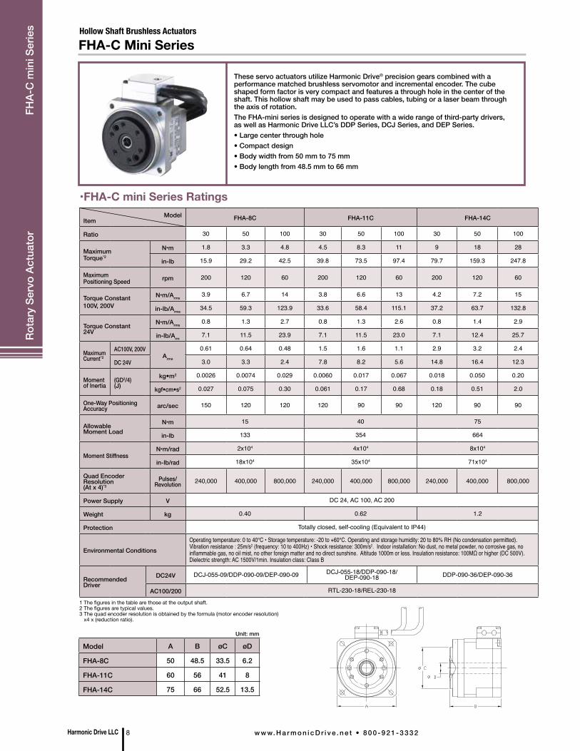
•FHA-C mini Series Ratings
These servo actuators utilize Harmonic Drive® precision gears combined with a performance matched brushless servomotor and incremental encoder. The cube shaped form factor is very compact and features a through hole in the center of the shaft. This hollow shaft may be used to pass cables, tubing or a laser beam through the axis of rotation.The FHA-mini series is designed to operate with a wide range of third-party drivers, as well as Harmonic Drive LLC’s DDP Series, DCJ Series, and DEP Series.• Large center through hole• Compact design• Body width from 50 mm to 75 mm• Body length from 48.5 mm to 66 mm
Hollow Shaft Brushless ActuatorsFHA-C Mini Series
Model A B øC øD
FHA-8C 50 48.5 33.5 6.2
FHA-11C 60 56 41 8
FHA-14C 75 66 52.5 13.5
Unit: mm
ModelItem FHA-8C FHA-11C FHA-14C
Ratio 30 50 100 30 50 100 30 50 100
Maximum Torque*2
N•m 1.8 3.3 4.8 4.5 8.3 11 9 18 28
in-lb 15.9 29.2 42.5 39.8 73.5 97.4 79.7 159.3 247.8
Maximum Positioning Speed rpm 200 120 60 200 120 60 200 120 60
Torque Constant100V, 200V
N•m/Arms3.9 6.7 14 3.8 6.6 13 4.2 7.2 15
in-lb/Arms34.5 59.3 123.9 33.6 58.4 115.1 37.2 63.7 132.8
Torque Constant24V
N•m/Arms0.8 1.3 2.7 0.8 1.3 2.6 0.8 1.4 2.9
in-lb/Arm7.1 11.5 23.9 7.1 11.5 23.0 7.1 12.4 25.7
Maximum Current*2
AC100V, 200VArms
0.61 0.64 0.48 1.5 1.6 1.1 2.9 3.2 2.4
DC 24V 3.0 3.3 2.4 7.8 8.2 5.6 14.8 16.4 12.3
Moment of Inertia
(GD2/4) (J)
kg•m2 0.0026 0.0074 0.029 0.0060 0.017 0.067 0.018 0.050 0.20
kgf•cm•s2 0.027 0.075 0.30 0.061 0.17 0.68 0.18 0.51 2.0
One-Way Positioning Accuracy arc/sec 150 120 120 120 90 90 120 90 90
Allowable Moment Load
N•m 15 40 75
in-lb 133 354 664
Moment StiffnessN•m/rad 2x10⁴ 4x10⁴ 8x10⁴
in-lb/rad 18x104 35x104 71x104
Quad Encoder Resolution (At x 4)*3
Pulses/Revolution 240,000 400,000 800,000 240,000 400,000 800,000 240,000 400,000 800,000
Power Supply V DC 24, AC 100, AC 200
Weight kg 0.40 0.62 1.2
Protection Totally closed, self-cooling (Equivalent to IP44)
Environmental ConditionsOperating temperature: 0 to 40°C • Storage temperature: -20 to +60°C. Operating and storage humidity: 20 to 80% RH (No condensation permitted).Vibration resistance : 25m/s2 (frequency: 10 to 400Hz) • Shock resistance: 300m/s2. Indoor installation: No dust, no metal powder, no corrosive gas, no inflammable gas, no oil mist, no other foreign matter and no direct sunshine. Altitude 1000m or less. Insulation resistance: 100MΩ or higher (DC 500V). Dielectric strength: AC 1500V/1min. Insulation class: Class B
Recommended Driver
DC24V DCJ-055-09/DDP-090-09/DEP-090-09 DCJ-055-18/DDP-090-18/ DEP-090-18 DDP-090-36/DEP-090-36
AC100/200 RTL-230-18/REL-230-18
Harmonic Drive LLC 8 w w w. H a r m o n i c D r i v e . n e t • 8 0 0 - 9 2 1 - 3 3 3 2
Rota
ry S
ervo
Act
uato
r FH
A-C
min
i Ser
ies
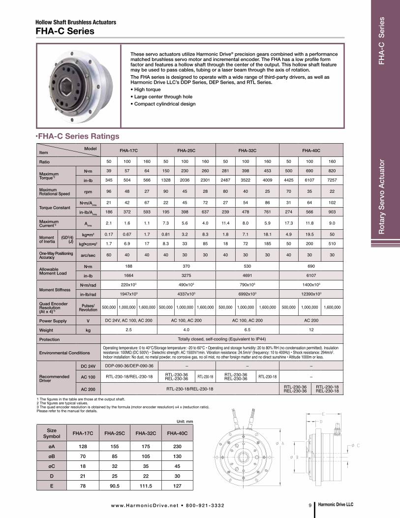
ModelItem FHA-17C FHA-25C FHA-32C FHA-40C
Ratio 50 100 160 50 100 160 50 100 160 50 100 160
Maximum Torque*2
N•m 39 57 64 150 230 260 281 398 453 500 690 820
in-lb 345 504 566 1328 2036 2301 2487 3522 4009 4425 6107 7257
Maximum Rotational Speed rpm 96 48 27 90 45 28 80 40 25 70 35 22
Torque ConstantN•m/Arms
21 42 67 22 45 72 27 54 86 31 64 102
in-lb/Arms186 372 593 195 398 637 239 478 761 274 566 903
Maximum Current*2 Arms
2.1 1.6 1.1 7.3 5.6 4.0 11.4 8.0 5.9 17.3 11.8 9.0
Moment of Inertia
(GD2/4) (J)
kg•m2 0.17 0.67 1.7 0.81 3.2 8.3 1.8 7.1 18.1 4.9 19.5 50
kgf•cm•s2 1.7 6.9 17 8.3 33 85 18 72 185 50 200 510
One-Way Positioning Accuracy arc/sec 60 40 40 40 30 30 40 30 30 40 30 30
Allowable Moment Load
N•m 188 370 530 690
in-lb 1664 3275 4691 6107
Moment StiffnessN•m/rad 220x103 490x103 790x103 1400x103
in-lb/rad 1947x103 4337x103 6992x103 12390x103
Quad Encoder Resolution (At x 4)*3
Pulses/Revolution 500,000 1,000,000 1,600,000 500,000 1,000,000 1,600,000 500,000 1,000,000 1,600,000 500,000 1,000,000 1,600,000
Power Supply V DC 24V, AC 100, AC 200 AC 100, AC 200 AC 100, AC 200 AC 200
Weight kg 2.5 4.0 6.5 12
Protection Totally closed, self-cooling (Equivalent to IP44)
Environmental ConditionsOperating temperature: 0 to 40°C/Storage temperature: -20 to 60°C • Operating and storage humidity: 20 to 80% RH (no condensation permitted). Insulation resistance: 100MΩ (DC 500V) • Dielectric strength: AC 1500V/1min. Vibration resistance: 24.5m/s2 (frequency: 10 to 400Hz) • Shock resistance: 294m/s2. Indoor installation: No dust, no metal powder, no corrosive gas, no oil mist, no other foreign matter and no direct sunshine • Altitude 1000m or less.
Recommended Driver
DC 24V DDP-090-36/DEP-090-36 – – –
AC 100 RTL-230-18/REL-230-18 RTL-230-36REL-230-36 RTL-230-18 RTL-230-36
REL-230-36 RTL-230-18 –
AC 200 RTL-230-18/REL-230-18 RTL-230-36REL-230-36
RTL-230-18REL-230-18
These servo actuators utilize Harmonic Drive® precision gears combined with a performance matched brushless servo motor and incremental encoder. The FHA has a low profile form factor and features a hollow shaft through the center of the output. This hollow shaft feature may be used to pass cables, tubing or a laser beam through the axis of rotation.The FHA series is designed to operate with a wide range of third-party drivers, as well as Harmonic Drive LLC’s DDP Series, DEP Series, and RTL Series. • High torque• Large center through hole• Compact cylindrical design
Hollow Shaft Brushless ActuatorsFHA-C Series
•FHA-C Series Ratings
1 The figures in the table are those at the output shaft.2 The figures are typical values.3 The quad encoder resolution is obtained by the formula (motor encoder resolution) x4 x (reduction ratio).Please refer to the manual for details.
SizeSymbol FHA-17C FHA-25C FHA-32C FHA-40C
øA 128 155 175 230
øB 70 85 105 130
øC 18 32 35 45
D 21 25 22 30
E 78 90.5 111.5 127
Unit: mm
Harmonic Drive LLCw w w. H a r m o n i c D r i v e . n e t • 8 0 0 - 9 2 1 - 3 3 3 2 9
Rota
ry S
ervo
Act
uato
r FH
A-C
Ser
ies
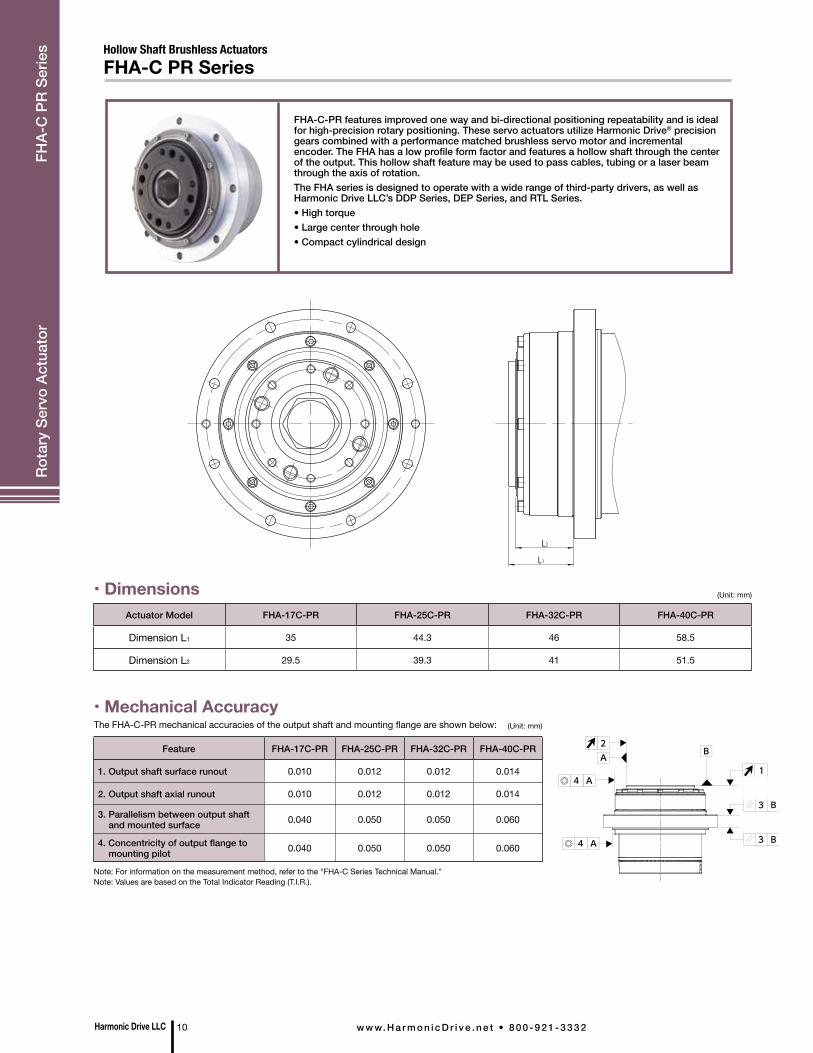
FHA-C-PR features improved one way and bi-directional positioning repeatability and is ideal for high-precision rotary positioning. These servo actuators utilize Harmonic Drive® precision gears combined with a performance matched brushless servo motor and incremental encoder. The FHA has a low profile form factor and features a hollow shaft through the center of the output. This hollow shaft feature may be used to pass cables, tubing or a laser beam through the axis of rotation.The FHA series is designed to operate with a wide range of third-party drivers, as well as Harmonic Drive LLC’s DDP Series, DEP Series, and RTL Series. • High torque• Large center through hole• Compact cylindrical design
Hollow Shaft Brushless ActuatorsFHA-C PR Series
L1
L2
• Mechanical Accuracy
• DimensionsActuator Model FHA-17C-PR FHA-25C-PR FHA-32C-PR FHA-40C-PR
Dimension L1 35 44.3 46 58.5
Dimension L2 29.5 39.3 41 51.5
Feature FHA-17C-PR FHA-25C-PR FHA-32C-PR FHA-40C-PR
1. Output shaft surface runout 0.010 0.012 0.012 0.014
2. Output shaft axial runout 0.010 0.012 0.012 0.014
3. Parallelism between output shaft and mounted surface 0.040 0.050 0.050 0.060
4. Concentricity of output flange to mounting pilot 0.040 0.050 0.050 0.060
(Unit: mm)
(Unit: mm)The FHA-C-PR mechanical accuracies of the output shaft and mounting flange are shown below:
Note: For information on the measurement method, refer to the "FHA-C Series Technical Manual."Note: Values are based on the Total Indicator Reading (T.I.R.).
Harmonic Drive LLC 10 w w w. H a r m o n i c D r i v e . n e t • 8 0 0 - 9 2 1 - 3 3 3 2
Rota
ry S
ervo
Act
uato
r FH
A-C
PR
Serie
s
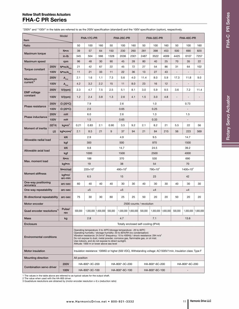
"200V" and "100V" in the table are referred to as the 200V specification (standard) and the 100V specification (option), respectively.
ItemFHA-17C-PR FHA-25C-PR FHA-32C-PR FHA-40C-PR
Ratio 50 100 160 50 100 160 50 100 160 50 100 160
Maximum torqueN•m 39 57 64 150 230 260 281 398 453 500 690 820
in-lb 345 504 566 1328 2036 2301 2487 3522 4009 4425 6107 7257
Maximum speed rpm 96 48 30 90 45 28 80 40 25 70 35 22
Torque constant200V N•m/Arms 21 42 67 22 45 72 27 54 86 31 64 102
100V N•m/Arms 11 21 33 11 22 36 13 27 43 - - -
Maximum current*2
200V Arms 2.1 1.6 1.1 7.3 5.6 4.0 11.4 8.0 5.9 17.3 11.8 9.0
100V Arms 4.2 3.2 2.2 15 11 8.0 23 16 12 - - -
EMF voltage constant
200V V/(rpm) 2.3 4.7 7.5 2.5 5.1 8.1 3.0 5.9 9.5 3.6 7.2 11.4
100V V/(rpm) 1.2 2.4 3.8 1.3 2.6 4.1 1.5 3.0 4.8 - - -
Phase resistance200V Ω (20οC) 7.9 2.6 1.0 0.73
100V Ω (20οC) 2.0 0.65 0.25 -
Phase inductance200V mH 6.0 2.6 1.3 1.5
100V mH 1.5 0.65 0.33 -
Moment of inertia(GD2/4) kg•m2 0.21 0.83 2.1 0.90 3.5 9.2 2.1 8.2 21 5.5 22 56
(J) kgf•cm•s2 2.1 8.5 21 9 37 94 21 84 215 56 223 569
Allowable radial loadkN 2.9 4.9 9.5 14.7
kgf 300 500 970 1500
Allowable axial loadkN 9.8 14.7 24.5 39.2
kgf 1000 1500 2500 4000
Max. moment loadN•m 188 370 530 690
kgf•m 19 38 54 70
Moment stiffnessN•m/rad 220×103 490×103 790×103 1400×103
kgf•m/arc-min 6.5 15 23 42
One-way positioning accuracy arc-sec 60 40 40 40 30 30 40 30 30 40 30 30
One-way repeatability arc-sec ±5 ±5 ±4 ±4
Bi-directional repeatability arc-sec 75 30 30 60 25 25 50 20 20 50 20 20
Motor encoder 2500 counts / revolution
Quad encoder resolutions*3 Pulse/rev 500,000 1,000,000 1,600,000 500,000 1,000,000 1,600,000 500,000 1,000,000 1,600,000 500,000 1,000,000 1,600,000
Mass kg 2.8 4.7 7.1 13.6
Enclosure Totally enclosed self-cooling (IP44)
Environmental conditions
Operating temperature: 0 to 40οC/storage temperature: -20 to 60οC Operating humidity / storage humidity: 20 to 80%RH (no condensation)Vibration resistance: 24.5m/s2 (frequency: 10 to 400Hz) / shock resistance: 294 m/s2
Do not expose to dust, metal powder, corrosive gas, flammable gas, or oil mist.Use indoors, and do not expose to direct sunlight. Altitude: 1000 m or lower above sea level
Motor insulation Insulation resistance: 100MΩ or higher (500 VDC), Withstanding voltage: AC1500V/1min, Insulation class: Type F
Mounting direction All position
Combination servo driver200V HA-800*-3C-200 HA-800*-3C-200 HA-800*-6C-200 HA-800*-6C-200
100V HA-800*-3C-100 HA-800*-6C-100 HA-800*-6C-100 -
1 The values in the table above are referred to as typical values for the output shaft.2 The value when used with the HA-800 driver. 3 Quadrature resolutions are obtained by (motor encoder resolution x 4) x (reduction ratio)
Model
Hollow Shaft Brushless ActuatorsFHA-C PR Series
Harmonic Drive LLCw w w. H a r m o n i c D r i v e . n e t • 8 0 0 - 9 2 1 - 3 3 3 2 11
Rota
ry S
ervo
Act
uato
r FH
A-C
PR
Serie
s
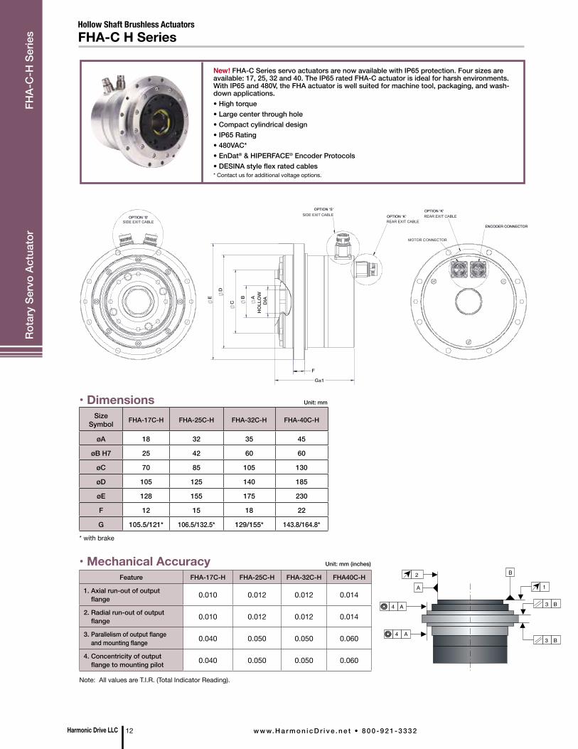
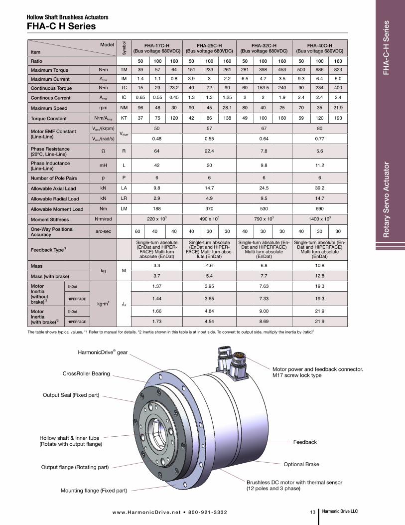
New! FHA-C Series servo actuators are now available with IP65 protection. Four sizes are available: 17, 25, 32 and 40. The IP65 rated FHA-C actuator is ideal for harsh environments. With IP65 and 480V, the FHA actuator is well suited for machine tool, packaging, and wash-down applications. • High torque• Large center through hole• Compact cylindrical design• IP65 Rating• 480VAC*• EnDat® & HIPERFACE® Encoder Protocols• DESINA style flex rated cables* Contact us for additional voltage options.
Hollow Shaft Brushless ActuatorsFHA-C H Series
Feature FHA-17C-H FHA-25C-H FHA-32C-H FHA40C-H
1. Axial run-out of output flange 0.010 0.012 0.012 0.014
2. Radial run-out of output flange 0.010 0.012 0.012 0.014
3. Parallelism of output flange and mounting flange 0.040 0.050 0.050 0.060
4. Concentricity of output flange to mounting pilot 0.040 0.050 0.050 0.060
Note: All values are T.I.R. (Total Indicator Reading).
* with brake
• Mechanical Accuracy
• DimensionsSize
Symbol FHA-17C-H FHA-25C-H FHA-32C-H FHA-40C-H
øA 18 32 35 45
øB H7 25 42 60 60
øC 70 85 105 130
øD 105 125 140 185
øE 128 155 175 230
F 12 15 18 22
G 105.5/121* 106.5/132.5* 129/155* 143.8/164.8*
Unit: mm
2
A 1
A4
3 B
3 B
A4
B
Unit: mm (inches)
Harmonic Drive LLC 12 w w w. H a r m o n i c D r i v e . n e t • 8 0 0 - 9 2 1 - 3 3 3 2
Rota
ry S
ervo
Act
uato
r FH
A-C
-H S
erie
s
OPTION 'S'
OPTION 'S' OPTION 'K'OPTION 'K'
ENCODER CONNECTOR
E
D
C
AH
OLL
OW
D
IAB
G±1
F
Hollow Shaft Brushless ActuatorsFHA-C H Series
Harmonic Drive LLCw w w. H a r m o n i c D r i v e . n e t • 8 0 0 - 9 2 1 - 3 3 3 2 13
Rota
ry S
ervo
Act
uato
r FH
A-C
-H S
erie
s
Model Item
FHA-17C-H(Bus voltage 680VDC)
FHA-25C-H(Bus voltage 680VDC)
FHA-32C-H(Bus voltage 680VDC)
FHA-40C-H(Bus voltage 680VDC)
Ratio 50 100 160 50 100 160 50 100 160 50 100 160
Maximum Torque N•m TM 39 57 64 151 233 261 281 398 453 500 686 823
Maximum Current Arms IM 1.4 1.1 0.8 3.9 3 2.2 6.5 4.7 3.5 9.3 6.4 5.0
Continuous Torque N•m TC 15 23 23.2 40 72 90 60 153.5 240 90 234 400
Continous Current Arms IC 0.65 0.55 0.45 1.3 1.3 1.25 2 2 1.9 2.4 2.4 2.4
Maximum Speed rpm NM 96 48 30 90 45 28.1 80 40 25 70 35 21.9
Torque Constant N•m/Arms KT 37 75 120 42 86 138 49 100 160 59 120 193
Motor EMF Constant(Line-Line)
Vrms/(krpm)VEMF
50 57 67 80
Vrms/(rad/s) 0.48 0.55 0.64 0.77
Phase Resistance(20°C, Line-Line) Ω R 64 22.4 7.8 5.6
Phase Inductance(Line-Line) mH L 42 20 9.8 11.2
Number of Pole Pairs p P 6 6 6 6
Allowable Axial Load kN LA 9.8 14.7 24.5 39.2
Allowable Radial Load kN LR 2.9 4.9 9.5 14.7
Allowable Moment Load Nm LM 188 370 530 690
Moment Stiffness N•m/rad 220 x 103 490 x 103 790 x 103 1400 x 103
One-Way Positional Accuracy arc-sec 60 40 40 40 30 30 40 30 30 40 30 30
Feedback Type*1
Single-turn absolute (EnDat and HIPER-
FACE) Multi-turn absolute (EnDat)
Single-turn absolute (EnDat and HIPER-
FACE) Multi-turn abso-lute (EnDat)
Single-turn absolute (En-Dat and HIPERFACE)
Multi-turn absolute (EnDat)
Single-turn absolute (En-Dat and HIPERFACE)
Multi-turn absolute (EnDat)
Masskg M
3.3 4.6 6.8 10.8
Mass (with brake) 3.7 5.4 7.7 12.8
Motor Inertia(without brake)*2
EnDat
kg•m2 JA
1.37 3.95 7.63 19.3
HIPERFACE 1.44 3.65 7.33 19.3
Motor Inertia(with brake)*2
EnDat 1.66 4.84 9.00 21.9
HIPERFACE 1.73 4.54 8.69 21.9
The table shows typical values. *1 Refer to manual for details. *2 Inertia shown in this table is at input side. To convert to output side, multiply the inertia by (ratio)2
Motor power and feedback connector. M17 screw lock type
HarmonicDrive® gear
CrossRoller Bearing
Output Seal (Fixed part)
Hollow shaft & Inner tube(Rotate with output flange)
Output flange (Rotating part)
Mounting flange (Fixed part)
Feedback
Optional Brake
Brushless DC motor with thermal sensor(12 poles and 3 phase)
Sym
bol
•SHA-CG Series Ratings
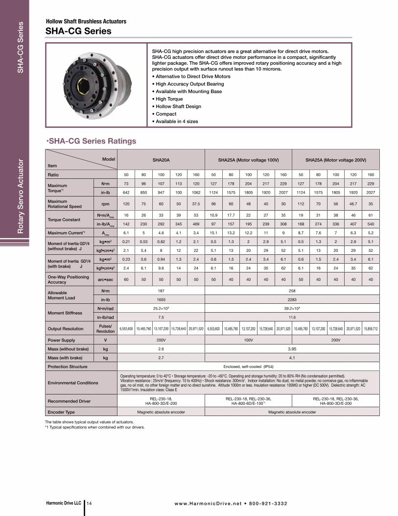
SHA-CG high precision actuators are a great alternative for direct drive motors. SHA-CG actuators offer direct drive motor performance in a compact, significantly lighter package. The SHA-CG offers improved rotary positioning accuracy and a high precision output with surface runout less than 10 microns.• Alternative to Direct Drive Motors• High Accuracy Output Bearing• Available with Mounting Base• High Torque• Hollow Shaft Design• Compact• Available in 4 sizes
Hollow Shaft Brushless ActuatorsSHA-CG Series
The table shows typical output values of actuators. *1 Typical specifications when combined with our drivers.
Model
ItemSHA20A SHA25A (Motor voltage 100V) SHA25A (Motor voltage 200V)
Ratio 50 80 100 120 160 50 80 100 120 160 50 80 100 120 160
Maximum Torque*1
N•m 73 96 107 113 120 127 178 204 217 229 127 178 204 217 229
in-lb 642 850 947 100 1062 1124 1575 1805 1920 2027 1124 1575 1805 1920 2027
Maximum Rotational Speed rpm 120 75 60 50 37.5 96 60 48 40 30 112 70 56 46.7 35
Torque ConstantN•m/Arms 16 26 33 39 53 10.9 17.7 22 27 35 19 31 38 46 61
in-lb/Arms 142 230 292 345 469 97 157 195 239 308 168 274 336 407 540
Maximum Current*1 Arms 6.1 5 4.6 4.1 3.4 15.1 13.2 12.2 11 9 8.7 7.6 7 6.3 5.2
Moment of Inertia GD2/4(without brake) J
kg•m2 0.21 0.53 0.82 1.2 2.1 0.5 1.3 2 2.9 5.1 0.5 1.3 2 2.9 5.1
kgf•cm•s2 2.1 5.4 8 12 22 5.1 13 20 29 52 5.1 13 20 29 52
Moment of Inertia GD2/4(with brake) J
kg•m2 0.23 0.6 0.94 1.3 2.4 0.6 1.5 2.4 3.4 6.1 0.6 1.5 2.4 3.4 6.1
kgf•cm•s2 2.4 6.1 9.6 14 24 6.1 16 24 35 62 6.1 16 24 35 62
One-Way Positioning Accuracy arc•sec 60 50 50 50 50 50 40 40 40 40 50 40 40 40 40
Allowable Moment Load
N•m 187 258
in-lb 1655 2283
Moment StiffnessN•m/rad 25.2×10⁴ 39.2×10⁴
in-lb/rad 7.5 11.6
Output Resolution Pulses/Revolution 6,553,600 10,485,760 13,107,200 15,728,640 20,971,520 6,553,600 10,485,760 13,107,200 15,728,640 20,971,520 10,485,760 13,107,200 15,728,640 20,971,520 15,859,712
Power Supply V 200V 100V 200V
Mass (without brake) kg 2.6 3.95
Mass (with brake) kg 2.7 4.1
Protection Structure Enclosed, self-cooled (IP54)
Environmental ConditionsOperating temperature: 0 to 40°C • Storage temperature: -20 to +60°C. Operating and storage humidity: 20 to 80% RH (No condensation permitted).Vibration resistance : 25m/s2 (frequency: 10 to 400Hz) • Shock resistance: 300m/s2. Indoor installation: No dust, no metal powder, no corrosive gas, no inflammable gas, no oil mist, no other foreign matter and no direct sunshine. Altitude 1000m or less. Insulation resistance: 100MΩ or higher (DC 500V). Dielectric strength: AC 1500V/1min. Insulation class: Class E
Recommended Driver REL-230-18, HA-800-3D/E-200
REL-230-18, REL-230-36, HA-800-6D/E-100*1
REL-230-18, REL-230-36, HA-800-3D/E-200
Encoder Type Magnetic absolute encoder Magnetic absolute encoder
Harmonic Drive LLC 14 w w w. H a r m o n i c D r i v e . n e t • 8 0 0 - 9 2 1 - 3 3 3 2
Rota
ry S
ervo
Act
uato
r SH
A-C
G S
erie
s
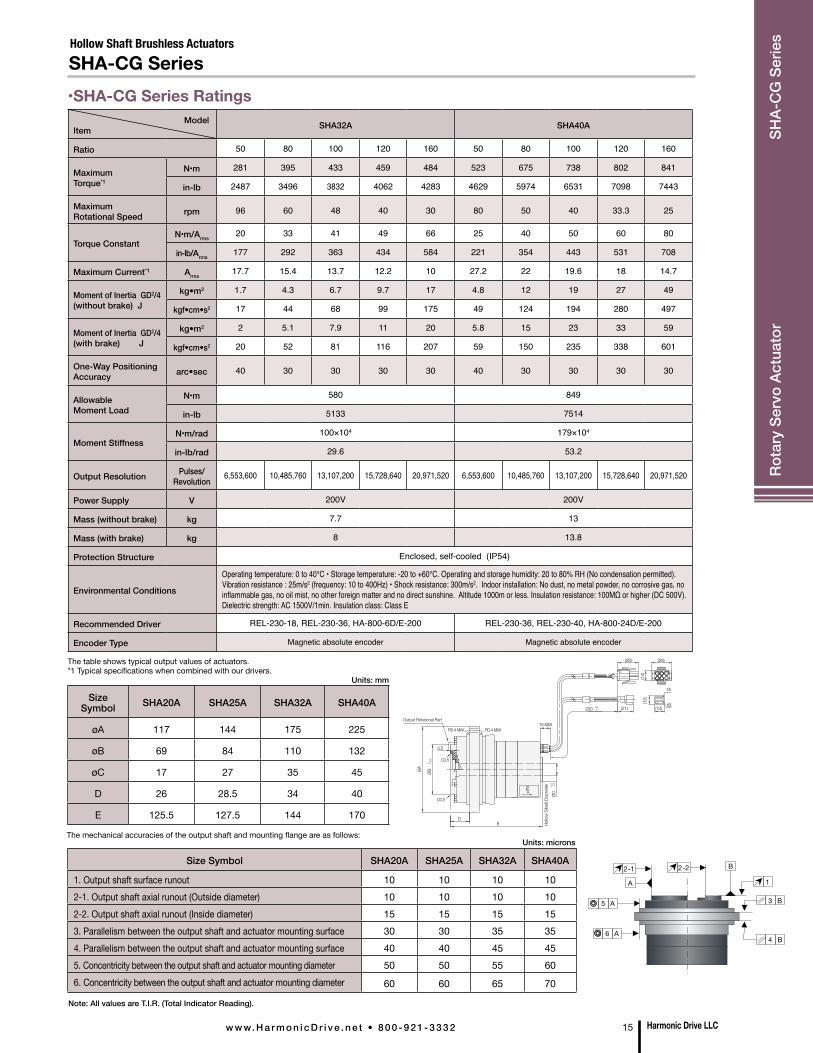
•SHA-CG Series Ratings
Hollow Shaft Brushless ActuatorsSHA-CG Series
ModelItem SHA32A SHA40A
Ratio 50 80 100 120 160 50 80 100 120 160
Maximum Torque*1
N•m 281 395 433 459 484 523 675 738 802 841
in-lb 2487 3496 3832 4062 4283 4629 5974 6531 7098 7443
Maximum Rotational Speed rpm 96 60 48 40 30 80 50 40 33.3 25
Torque ConstantN•m/Arms
20 33 41 49 66 25 40 50 60 80
in-lb/Arms177 292 363 434 584 221 354 443 531 708
Maximum Current*1 Arms17.7 15.4 13.7 12.2 10 27.2 22 19.6 18 14.7
Moment of Inertia GD2/4(without brake) J
kg•m2 1.7 4.3 6.7 9.7 17 4.8 12 19 27 49
kgf•cm•s2 17 44 68 99 175 49 124 194 280 497
Moment of Inertia GD2/4 (with brake) J
kg•m2 2 5.1 7.9 11 20 5.8 15 23 33 59
kgf•cm•s2 20 52 81 116 207 59 150 235 338 601
One-Way Positioning Accuracy arc•sec 40 30 30 30 30 40 30 30 30 30
Allowable Moment Load
N•m 580 849
in-lb 5133 7514
Moment StiffnessN•m/rad 100×104 179×104
in-lb/rad 29.6 53.2
Output Resolution Pulses/Revolution 6,553,600 10,485,760 13,107,200 15,728,640 20,971,520 6,553,600 10,485,760 13,107,200 15,728,640 20,971,520
Power Supply V 200V 200V
Mass (without brake) kg 7.7 13
Mass (with brake) kg 8 13.8
Protection Structure Enclosed, self-cooled (IP54)
Environmental Conditions
Operating temperature: 0 to 40°C • Storage temperature: -20 to +60°C. Operating and storage humidity: 20 to 80% RH (No condensation permitted). Vibration resistance : 25m/s2 (frequency: 10 to 400Hz) • Shock resistance: 300m/s2. Indoor installation: No dust, no metal powder, no corrosive gas, no inflammable gas, no oil mist, no other foreign matter and no direct sunshine. Altitude 1000m or less. Insulation resistance: 100MΩ or higher (DC 500V). Dielectric strength: AC 1500V/1min. Insulation class: Class E
Recommended Driver REL-230-18, REL-230-36, HA-800-6D/E-200 REL-230-36, REL-230-40, HA-800-24D/E-200
Encoder Type Magnetic absolute encoder Magnetic absolute encoder
The table shows typical output values of actuators. *1 Typical specifications when combined with our drivers.
The mechanical accuracies of the output shaft and mounting flange are as follows:
Size Symbol SHA20A SHA25A SHA32A SHA40A
øA 117 144 175 225
øB 69 84 110 132
øC 17 27 35 45
D 26 28.5 34 40
E 125.5 127.5 144 170
Units: mm
Note: All values are T.I.R. (Total Indicator Reading).
Size Symbol SHA20A SHA25A SHA32A SHA40A
1. Output shaft surface runout 10 10 10 102-1. Output shaft axial runout (Outside diameter) 10 10 10 102-2. Output shaft axial runout (Inside diameter) 15 15 15 153. Parallelism between the output shaft and actuator mounting surface 30 30 35 354. Parallelism between the output shaft and actuator mounting surface 40 40 45 455. Concentricity between the output shaft and actuator mounting diameter 50 50 55 606. Concentricity between the output shaft and actuator mounting diameter 60 60 65 70
Units: microns
Output Rotational Part
Hollo
w S
haft
Diam
eter
3.5
(21) (13)
(12)
(14)
1B
1A
(28)(28)
15 MAX
D
R0.4 MAX
C0.5
R0.4 MAX
C0.5
ØA ØB 0 -0
.030
E
N.P
ØC+0
.5 -0.2
+35 0200
2-1
A 1
A6
3 B
4 B
2-2
A5
B
Harmonic Drive LLCw w w. H a r m o n i c D r i v e . n e t • 8 0 0 - 9 2 1 - 3 3 3 2 15
Rota
ry S
ervo
Act
uato
r SH
A-C
G S
erie
s
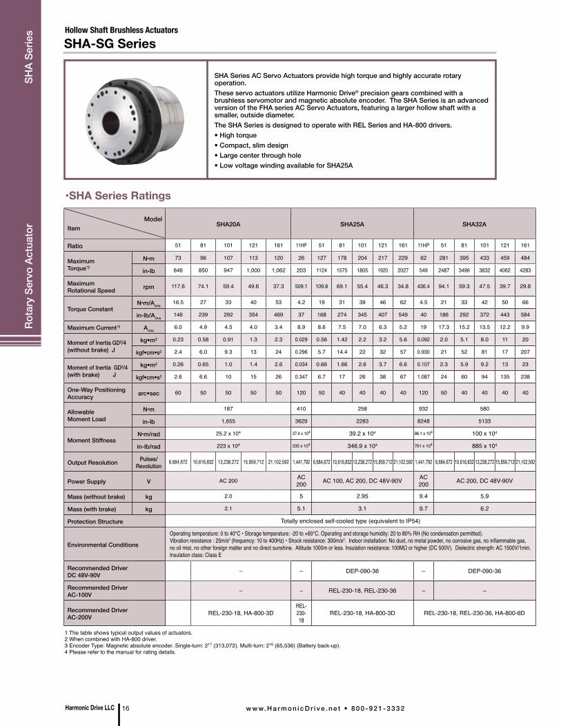
•SHA Series Ratings
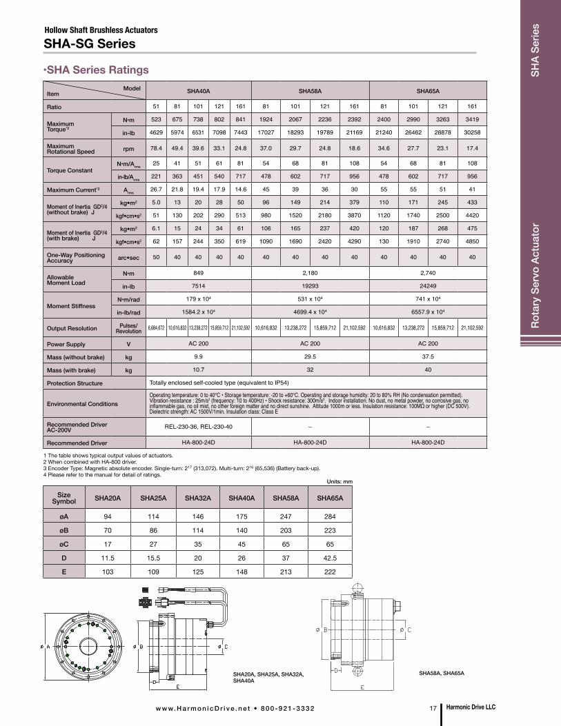
SHA Series AC Servo Actuators provide high torque and highly accurate rotary operation.These servo actuators utilize Harmonic Drive® precision gears combined with a brushless servomotor and magnetic absolute encoder. The SHA Series is an advanced version of the FHA series AC Servo Actuators, featuring a larger hollow shaft with a smaller, outside diameter.The SHA Series is designed to operate with REL Series and HA-800 drivers.• High torque• Compact, slim design• Large center through hole• Low voltage winding available for SHA25A
Hollow Shaft Brushless ActuatorsSHA-SG Series
1 The table shows typical output values of actuators.2 When combined with HA-800 driver.3 Encoder Type: Magnetic absolute encoder. Single-turn: 217 (313,072). Multi-turn: 216 (65,536) (Battery back-up).4 Please refer to the manual for rating details.
Model
Item SHA20A SHA25A SHA32A
Ratio 51 81 101 121 161 11HP 51 81 101 121 161 11HP 51 81 101 121 161
Maximum Torque*2
N•m 73 96 107 113 120 26 127 178 204 217 229 62 281 395 433 459 484
in-lb 646 850 947 1,000 1,062 203 1124 1575 1805 1920 2027 549 2487 3496 3832 4062 4283
Maximum Rotational Speed rpm 117.6 74.1 59.4 49.6 37.3 509.1 109.8 69.1 55.4 46.3 34.8 436.4 94.1 59.3 47.5 39.7 29.8
Torque ConstantN•m/Arms
16.5 27 33 40 53 4.2 19 31 39 46 62 4.5 21 33 42 50 66
in-lb/Arms146 239 292 354 469 37 168 274 345 407 549 40 186 292 372 443 584
Maximum Current*2 Arms6.0 4.9 4.5 4.0 3.4 8.9 8.6 7.5 7.0 6.3 5.2 19 17.3 15.2 13.5 12.2 9.9
Moment of Inertia GD2/4(without brake) J
kg•m2 0.23 0.58 0.91 1.3 2.3 0.029 0.56 1.42 2.2 3.2 5.6 0.092 2.0 5.1 8.0 11 20
kgf•cm•s2 2.4 6.0 9.3 13 24 0.296 5.7 14.4 22 32 57 0.930 21 52 81 17 207
Moment of Inertia GD2/4(with brake) J
kg•m2 0.26 0.65 1.0 1.4 2.6 0.034 0.66 1.66 2.6 3.7 6.6 0.107 2.3 5.9 9.2 13 23
kgf•cm•s2 2.6 6.6 10 15 26 0.347 6.7 17 26 38 67 1.087 24 60 94 135 238
One-Way Positioning Accuracy arc•sec 60 50 50 50 50 120 50 40 40 40 40 120 50 40 40 40 40
Allowable Moment Load
N•m 187 410 258 932 580
in-lb 1,655 3629 2283 8248 5133
Moment StiffnessN•m/rad 25.2 x 10⁴ 37.4 x 10⁴ 39.2 x 10⁴ 86.1 x 10⁴ 100 x 104
in-lb/rad 223 x 104 335 x 104 346.9 x 10⁴ 761 x 104 885 x 104
Output Resolution Pulses/Revolution
6,684,672 10,616,832 13,238,272 15,859,712 21,102,592 1,441,792 6,684,672 10,616,832 13,238,272 15,859,712 21,102,592 1,441,792 6,684,672 10,616,832 13,238,272 15,859,712 21,102,592
Power Supply V AC 200 AC 200 AC 100, AC 200, DC 48V-90V AC
200 AC 200, DC 48V-90V
Mass (without brake) kg 2.0 5 2.95 9.4 5.9
Mass (with brake) kg 2.1 5.1 3.1 9.7 6.2
Protection Structure Totally enclosed self-cooled type (equivalent to IP54)
Environmental Conditions
Operating temperature: 0 to 40°C • Storage temperature: -20 to +60°C. Operating and storage humidity: 20 to 80% RH (No condensation permitted).Vibration resistance : 25m/s2 (frequency: 10 to 400Hz) • Shock resistance: 300m/s2. Indoor installation: No dust, no metal powder, no corrosive gas, no inflammable gas, no oil mist, no other foreign matter and no direct sunshine. Altitude 1000m or less. Insulation resistance: 100MΩ or higher (DC 500V). Dielectric strength: AC 1500V/1min. Insulation class: Class E
Recommended DriverDC 48V-90V
– – DEP-090-36 – DEP-090-36
Recommended DriverAC-100V
– – REL-230-18, REL-230-36 – –
Recommended DriverAC-200V REL-230-18, HA-800-3D
REL-230-18
REL-230-18, HA-800-3D REL-230-18, REL-230-36, HA-800-6D
Harmonic Drive LLC 16 w w w. H a r m o n i c D r i v e . n e t • 8 0 0 - 9 2 1 - 3 3 3 2
Rota
ry S
ervo
Act
uato
r SH
A Se
ries
•SHA Series Ratings
Hollow Shaft Brushless ActuatorsSHA-SG Series
SHA20A, SHA25A, SHA32A, SHA40A
SHA58A, SHA65A
Size Symbol SHA20A SHA25A SHA32A SHA40A SHA58A SHA65A
øA 94 114 146 175 247 284
øB 70 86 114 140 203 223
øC 17 27 35 45 65 65
D 11.5 15.5 20 26 37 42.5
E 103 109 125 148 213 222
Units: mm
ModelItem SHA40A SHA58A SHA65A
Ratio 51 81 101 121 161 81 101 121 161 81 101 121 161
Maximum Torque*2
N•m 523 675 738 802 841 1924 2067 2236 2392 2400 2990 3263 3419
in-lb 4629 5974 6531 7098 7443 17027 18293 19789 21169 21240 26462 28878 30258
Maximum Rotational Speed rpm 78.4 49.4 39.6 33.1 24.8 37.0 29.7 24.8 18.6 34.6 27.7 23.1 17.4
Torque ConstantN•m/Arms
25 41 51 61 81 54 68 81 108 54 68 81 108
in-lb/Arms221 363 451 540 717 478 602 717 956 478 602 717 956
Maximum Current*2 Arms26.7 21.8 19.4 17.9 14.6 45 39 36 30 55 55 51 41
Moment of Inertia GD2/4(without brake) J
kg•m2 5.0 13 20 28 50 96 149 214 379 110 171 245 433
kgf•cm•s2 51 130 202 290 513 980 1520 2180 3870 1120 1740 2500 4420
Moment of Inertia GD2/4(with brake) J
kg•m2 6.1 15 24 34 61 106 165 237 420 120 187 268 475
kgf•cm•s2 62 157 244 350 619 1090 1690 2420 4290 130 1910 2740 4850
One-Way Positioning Accuracy arc•sec 50 40 40 40 40 40 40 40 40 40 40 40 40
Allowable Moment Load
N•m 849 2,180 2,740
in-lb 7514 19293 24249
Moment StiffnessN•m/rad 179 x 104 531 x 104 741 x 104
in-lb/rad 1584.2 x 104 4699.4 x 104 6557.9 x 104
Output Resolution Pulses/Revolution 6,684,672 10,616,832 13,238,272 15,859,712 21,102,592 10,616,832 13,238,272 15,859,712 21,102,592 10,616,832 13,238,272 15,859,712 21,102,592
Power Supply V AC 200 AC 200 AC 200
Mass (without brake) kg 9.9 29.5 37.5
Mass (with brake) kg 10.7 32 40
Protection Structure Totally enclosed self-cooled type (equivalent to IP54)
Environmental ConditionsOperating temperature: 0 to 40°C • Storage temperature: -20 to +60°C. Operating and storage humidity: 20 to 80% RH (No condensation permitted).Vibration resistance : 25m/s2 (frequency: 10 to 400Hz) • Shock resistance: 300m/s2. Indoor installation: No dust, no metal powder, no corrosive gas, no inflammable gas, no oil mist, no other foreign matter and no direct sunshine. Altitude 1000m or less. Insulation resistance: 100MΩ or higher (DC 500V). Dielectric strength: AC 1500V/1min. Insulation class: Class E
Recommended DriverAC-200V REL-230-36, REL-230-40 – –
Recommended Driver HA-800-24D HA-800-24D HA-800-24D
1 The table shows typical output values of actuators.2 When combined with HA-800 driver.3 Encoder Type: Magnetic absolute encoder. Single-turn: 217 (313,072). Multi-turn: 216 (65,536) (Battery back-up).4 Please refer to the manual for detail of ratings.
Harmonic Drive LLCw w w. H a r m o n i c D r i v e . n e t • 8 0 0 - 9 2 1 - 3 3 3 2 17
Rota
ry S
ervo
Act
uato
r SH
A Se
ries

•FLA Series Ratings
The new ultra-flat, ultra-light brushless actuators combine our high-precision/high-performance reducers with a compact, high-output brushless DC motor. FLA actuators are available with our high-speed, high-efficiency Harmonic Planetary® gearhead or with our high-precision, high-torque Harmonic Drive® reducer.• Ultra-Flat Shape• Multiple Options Available: Three sizes, three ratios and two voltages• Light Weight• Designed to operate with a wide range of third-party servo drives
Brushless ActuatorsFLA Series
ModelItem FLA-11A-08HP FLA-14A-08HP FLA-17A-09HP
Ratio 8 8 9
Maximum Torque N•m 1.8 3.7 7.3
Allowable Continuous Torque N•m 0.6 1.2 3
Maximum Speed rpm 500 500 500
Allowable Continuous Speed rpm 100 100 100
Maximum Current (24VDC) Arms 8.7 18.0 26.2
Maximum Current (48VDC) Arms 4.5 9.6 13.6
Allowable Continuous Current (24VDC) Arms 3.0 6.0 10.4
Allowable Continuous Current (48VDC) Arms 1.6 3.0 5.3
Moment of Inertia (GD2/4) kgm2 0.00013 0.00039 0.001
Allowable Moment Load v 1.2 1.6 2.0
Moment Stiffness N•m/rad 2.0 x 10³ 3.3 x 10³ 4.4 x 10³
Motor Position Sensor Hall sensor
Positioning Resolution per Motor Rotation pls/rev 30 30 30
Output Shaft Resolution pls/rev 240 240 270
Weight g 390 620 870
Enclosure Fully enclosed self-cooling (IP40)
ModelItem FLA-11A-xxFB FLA-14A-xxFB FLA-17A-xxFB
Ratio 50 100 50 100 50 100
Maximum Torque N•m 6.7 11 11.2 18.2 23 34
Allowable Continuous Torque N•m 1.7 2.4 2.6 3.8 7.9 11.4
Maximum Speed rpm 100 50 100 50 100 50
Allowable Continuous Speed rpm 60 30 60 30 60 30
Maximum Current (24VDC) Arms 6.0 5.0 9.7 8.7 18.4 14.3
Maximum Current (48VDC) Arms 3.1 2.6 4.8 4.2 9.4 7.2
Allowable Continuous Current (24VDC) Arms 1.9 1.7 3.0 2.5 6.8 5.3
Allowable Continuous Current (48VDC) Arms 1.0 0.8 1.5 1.2 3.4 2.9
Moment of Inertia (GD2/4) kgm2 0.0073 0.029 0.019 0.077 0.048 0.19
Allowable Moment Load v 1.2 1.6 2.0
Moment Stiffness N•m/rad 2.0 x 10³ 3.3 x 10³ 4.4 x 10³
Motor Position Sensor Hall sensor
Positioning Resolution per Motor Rotation pls/rev 30 30 30
Output Shaft Resolution pls/rev 1,500 3,000 1,500 3,000 1,500 3,000
Weight g 420 720 940
Enclosure Fully enclosed self-cooling (IP40)
Harmonic Drive LLC 18 w w w. H a r m o n i c D r i v e . n e t • 8 0 0 - 9 2 1 - 3 3 3 2
Rota
ry S
ervo
Act
uato
r FL
A Se
ries
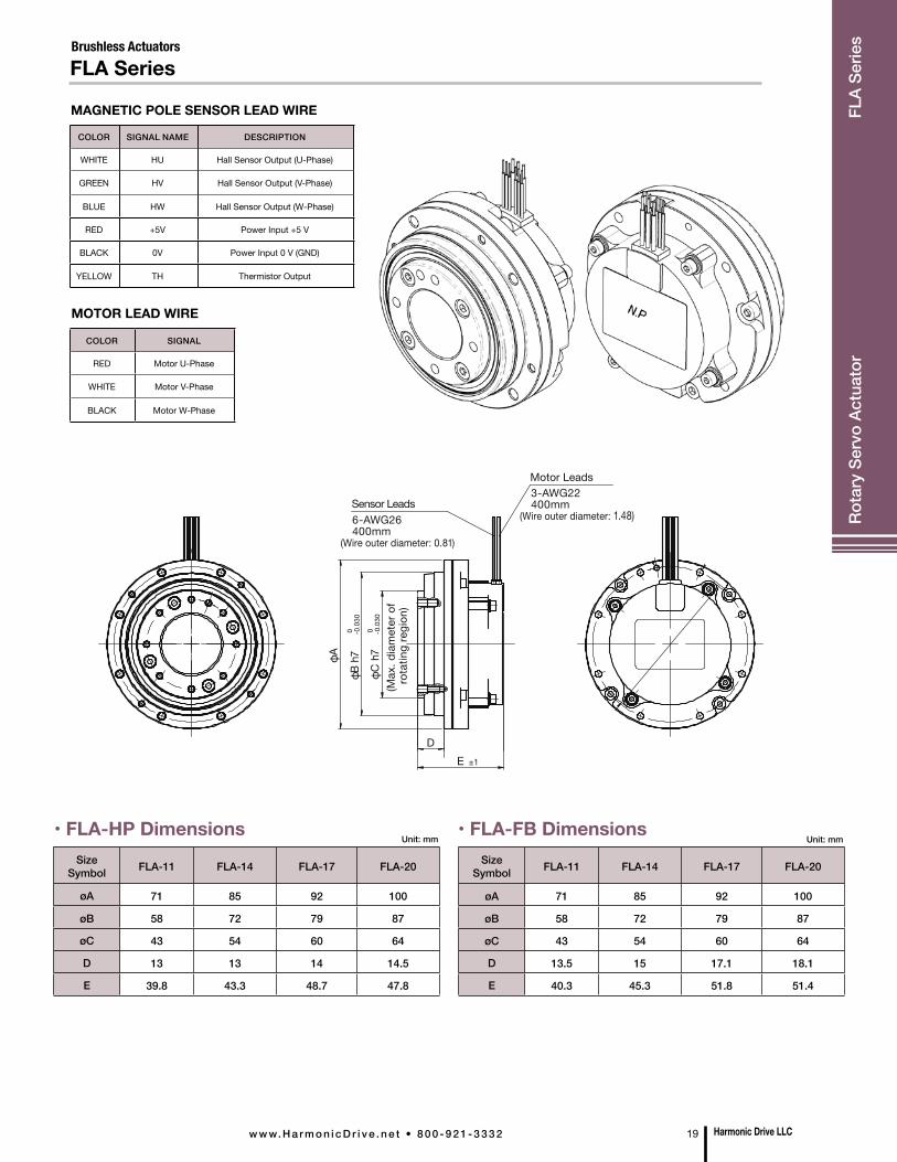
Brushless ActuatorsFLA Series
MAGNETIC POLE SENSOR LEAD WIRE
MOTOR LEAD WIRE
COLOR SIGNAL NAME DESCRIPTION
WHITE HU Hall Sensor Output (U-Phase)
GREEN HV Hall Sensor Output (V-Phase)
BLUE HW Hall Sensor Output (W-Phase)
RED +5V Power Input +5 V
BLACK 0V Power Input 0 V (GND)
YELLOW TH Thermistor Output
COLOR SIGNAL
RED Motor U-Phase
WHITE Motor V-Phase
BLACK Motor W-Phase
SizeSymbol FLA-11 FLA-14 FLA-17 FLA-20
øA 71 85 92 100
øB 58 72 79 87
øC 43 54 60 64
D 13 13 14 14.5
E 39.8 43.3 48.7 47.8
Unit: mm• FLA-HP Dimensions
SizeSymbol FLA-11 FLA-14 FLA-17 FLA-20
øA 71 85 92 100
øB 58 72 79 87
øC 43 54 60 64
D 13.5 15 17.1 18.1
E 40.3 45.3 51.8 51.4
Unit: mm
Motor Leads3-AWG22400mm
(Wire outer diameter: 1.48)
E ±1
D
Sensor Leads6-AWG26400mm
(Wire outer diameter: 0.81)
φA
φB h
7
φC h
7 (M
ax. d
iam
eter
of
rota
ting
regi
on)
0 -0.0
30
0 -0.0
30
• FLA-FB Dimensions
Harmonic Drive LLCw w w. H a r m o n i c D r i v e . n e t • 8 0 0 - 9 2 1 - 3 3 3 2 19
Rota
ry S
ervo
Act
uato
r FL
A Se
ries
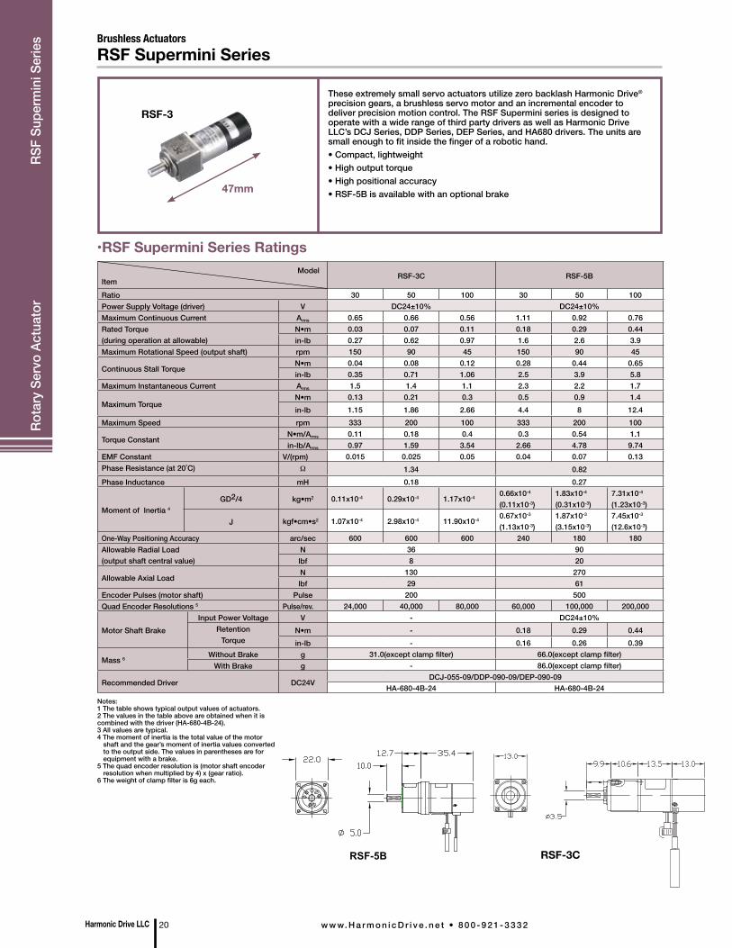
Brushless ActuatorsRSF Supermini Series
RSF-3
47mm
These extremely small servo actuators utilize zero backlash Harmonic Drive® precision gears, a brushless servo motor and an incremental encoder to deliver precision motion control. The RSF Supermini series is designed to operate with a wide range of third party drivers as well as Harmonic Drive LLC’s DCJ Series, DDP Series, DEP Series, and HA680 drivers. The units are small enough to fit inside the finger of a robotic hand.• Compact, lightweight • High output torque• High positional accuracy• RSF-5B is available with an optional brake
RSF-3C RSF-5B
•RSF Supermini Series Ratings
Notes:1 The table shows typical output values of actuators.2 The values in the table above are obtained when it is combined with the driver (HA-680-4B-24).3 All values are typical.4 The moment of inertia is the total value of the motor shaft and the gear’s moment of inertia values converted to the output side. The values in parentheses are for equipment with a brake.5 The quad encoder resolution is (motor shaft encoder resolution when multiplied by 4) x (gear ratio).6 The weight of clamp filter is 6g each.
ModelItem
RSF-3C RSF-5B
Ratio 30 50 100 30 50 100Power Supply Voltage (driver) V DC24±10% DC24±10%Maximum Continuous Current Arms 0.65 0.66 0.56 1.11 0.92 0.76Rated Torque(during operation at allowable)
N•m 0.03 0.07 0.11 0.18 0.29 0.44in-lb 0.27 0.62 0.97 1.6 2.6 3.9
Maximum Rotational Speed (output shaft) rpm 150 90 45 150 90 45
Continuous Stall TorqueN•m 0.04 0.08 0.12 0.28 0.44 0.65in-lb 0.35 0.71 1.06 2.5 3.9 5.8
Maximum Instantaneous Current Arms 1.5 1.4 1.1 2.3 2.2 1.7
Maximum TorqueN•m 0.13 0.21 0.3 0.5 0.9 1.4in-lb 1.15 1.86 2.66 4.4 8 12.4
Maximum Speed rpm 333 200 100 333 200 100
Torque ConstantN•m/Arms 0.11 0.18 0.4 0.3 0.54 1.1in-lb/Arms 0.97 1.59 3.54 2.66 4.78 9.74
EMF Constant V/(rpm) 0.015 0.025 0.05 0.04 0.07 0.13Phase Resistance (at 20˚C) Ω 1.34 0.82Phase Inductance mH 0.18 0.27
Moment of Inertia 4
GD2/4 kg•m2 0.11x10⁻⁴ 0.29x10⁻⁴ 1.17x10⁻⁴ 0.66x10⁻⁴
(0.11x10⁻³)1.83x10⁻⁴
(0.31x10⁻³)7.31x10⁻⁴
(1.23x10⁻³)
J kgf•cm•s2 1.07x10⁻⁴ 2.98x10⁻⁴ 11.90x10⁻⁴ 0.67x10⁻³
(1.13x10⁻³)1.87x10⁻³
(3.15x10⁻³)7.45x10⁻³
(12.6x10⁻³)One-Way Positioning Accuracy arc/sec 600 600 600 240 180 180Allowable Radial Load(output shaft central value)
N 36 90lbf 8 20
Allowable Axial LoadN 130 270lbf 29 61
Encoder Pulses (motor shaft) Pulse 200 500Quad Encoder Resolutions 5 Pulse/rev. 24,000 40,000 80,000 60,000 100,000 200,000
Motor Shaft BrakeInput Power Voltage V - DC24±10%
RetentionTorque
N•m - 0.18 0.29 0.44in-lb - 0.16 0.26 0.39
Mass 6 Without Brake g 31.0(except clamp filter) 66.0(except clamp filter)With Brake g - 86.0(except clamp filter)
Recommended Driver DC24VDCJ-055-09/DDP-090-09/DEP-090-09
HA-680-4B-24 HA-680-4B-24
RSF-3C
Harmonic Drive LLC 20 w w w. H a r m o n i c D r i v e . n e t • 8 0 0 - 9 2 1 - 3 3 3 2
Rota
ry S
ervo
Act
uato
r
RSF
Supe
rmin
i Ser
ies

Brushless Actuators
These brushless servo actuators utilize zero backlash Harmonic Drive® precision gears for precise motion control. The RSF Mini Series is designed to operate with a wide range of third party drivers as well as Harmonic Drive LLC’s DCJ Series, DDP Series, DEP Series, and HA680 drivers.• Exceptional positional accuracy• Compact design
•RSF Mini Series Ratings
Notes:1 The table shows output values of the actuator.2 All specifications are applicable for actuators mounted on an aluminum heat sink of size: 150 x 150 x 6(mm).3 Values for saturated actuator temperature. Other values are for actuator temperature of 20°C.4 Values are during operation at allowable continuous rotation speed. 5 All values are typical.6 Quad encoder resolution is (motor shaft encoder resolution) x 4 x (gear ratio).7 The specifications above are based on using HA-680 driver.
RSF-Mini Series
Model A B C D ø Eh7 ø F G
RSF-8B 124.3 21.8 76.5 26 21 34.5 7.5
RSF-11B 141.7 25 90.7 26 24 32.5 9.5
RSF-14B 168.5 28 114.5 26 30 32.5 11.5
ModelItem
RSF-8B RSF-11B RSF-14B
Ratio 30 50 100 30 50 100 30 50 100Power Suppy Voltage V DC24
Maximum Torque*3 N•m 1.8 3.3 4.8 4.5 8.3 11 9 18 28in-lb 15.9 29.2 42.5 39.8 73.5 97.4 79.7 159 248
Maximum Speed*3 rpm 200 120 60 200 120 60 200 120 60Maximum Current*3 Arms 3.8 3.9 2.9 14.4 15.8 9.4 14.4 17.2 12.3
Allowable Continuous Torque*3, 4N•m 0.78 1.4 2.0 1.1 2.0 4.0 1.7 3.0 6.0in-lb 6.9 12.4 17.7 9.7 17.7 35.4 15.0 26.6 53.1
Allowable Continuous Current*3, 4 Arms 2.0 2.0 1.5 5.0 4.9 4.9 4.9 4.7 4.7Allowable Continuous Speed*3 rpm 100 60 30 100 60 30 100 60 30Torque Constant N•m/Arms 0.62 1.1 2.1 0.4 0.66 1.5 0.76 1.3 2.6EMF Constant V(rpm) 0.07 0.11 0.22 0.04 0.07 0.15 0.08 0.13 0.28Phase Resistance Ω (25°C) 0.93 0.19 0.23Phase Inductance mH 0.45 0.1 0.19
Moment of InertiaGD2/4
×10-2
k•gm20.06 0.16 0.65 0.18 0.49 2.0 0.41 1.1 4.5
J×10-2
kgf•cm•s20.6 1.7 6.6 1.8 5.0 20 4.1 11 46
Allowable Radial LoadN 196 245 392lbf 44 55 88
Allowable Axial LoadN 98 196 392lbf 22 44 88
One-Way Positioning Accuracy arc/sec 180 150 150 150 120 120 150 120 120Quad Encoder Resolutions*6 p/rev 120000 200000 400000 120000 200000 400000 120000 200000 400000Mass kg 0.3 0.5 0.8Insulation Class BInsulation Resistance 100M Ω (DC500V) or moreWithstanding Voltage AC500V/1 min
Recommended Driver DC24V DCJ-055-09/DDP-090-09/DEP-090-09/HA-680-4B-24 DDP-090-36/DEP-090-36/HA-680-6B-24
Harmonic Drive LLCw w w. H a r m o n i c D r i v e . n e t • 8 0 0 - 9 2 1 - 3 3 3 2 21
Rota
ry S
ervo
Act
uato
r R
SF M
ini S
erie
s
Harmonic Drive LLC 22 w w w. H a r m o n i c D r i v e . n e t • 8 0 0 - 9 2 1 - 3 3 3 2
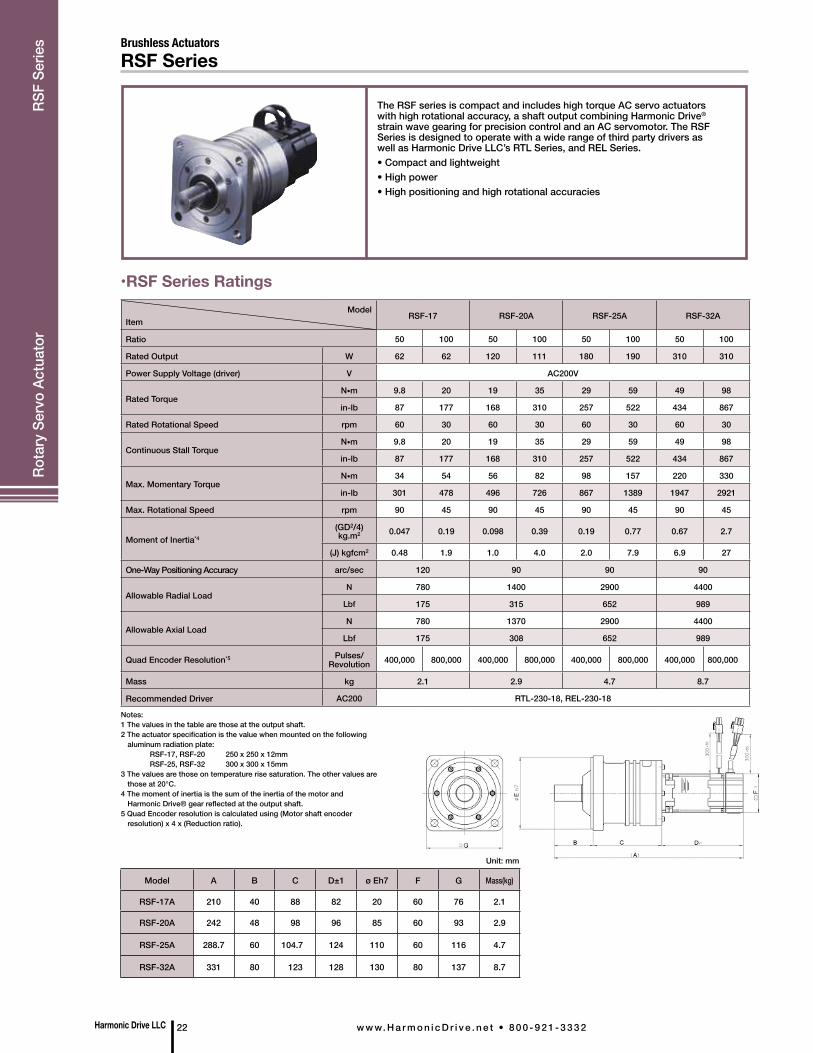
Brushless ActuatorsRSF Series
The RSF series is compact and includes high torque AC servo actuators with high rotational accuracy, a shaft output combining Harmonic Drive® strain wave gearing for precision control and an AC servomotor. The RSF Series is designed to operate with a wide range of third party drivers as well as Harmonic Drive LLC’s RTL Series, and REL Series.• Compact and lightweight• High power• High positioning and high rotational accuracies
ModelItem
RSF-17 RSF-20A RSF-25A RSF-32A
Ratio 50 100 50 100 50 100 50 100
Rated Output W 62 62 120 111 180 190 310 310
Power Supply Voltage (driver) V AC200V
Rated TorqueN•m 9.8 20 19 35 29 59 49 98
in-lb 87 177 168 310 257 522 434 867
Rated Rotational Speed rpm 60 30 60 30 60 30 60 30
Continuous Stall TorqueN•m 9.8 20 19 35 29 59 49 98
in-lb 87 177 168 310 257 522 434 867
Max. Momentary Torque N•m 34 54 56 82 98 157 220 330
in-lb 301 478 496 726 867 1389 1947 2921
Max. Rotational Speed rpm 90 45 90 45 90 45 90 45
Moment of Inertia*4 (GD2/4) kg.m2 0.047 0.19 0.098 0.39 0.19 0.77 0.67 2.7
(J) kgfcm2 0.48 1.9 1.0 4.0 2.0 7.9 6.9 27
One-Way Positioning Accuracy arc/sec 120 90 90 90
Allowable Radial LoadN 780 1400 2900 4400
Lbf 175 315 652 989
Allowable Axial LoadN 780 1370 2900 4400
Lbf 175 308 652 989
Quad Encoder Resolution*5 Pulses/Revolution 400,000 800,000 400,000 800,000 400,000 800,000 400,000 800,000
Mass kg 2.1 2.9 4.7 8.7
Recommended Driver AC200 RTL-230-18, REL-230-18
•RSF Series Ratings
Notes:1 The values in the table are those at the output shaft.2 The actuator specification is the value when mounted on the following aluminum radiation plate: RSF-17, RSF-20 250 x 250 x 12mm RSF-25, RSF-32 300 x 300 x 15mm 3 The values are those on temperature rise saturation. The other values are those at 20°C. 4 The moment of inertia is the sum of the inertia of the motor and Harmonic Drive® gear reflected at the output shaft.5 Quad Encoder resolution is calculated using (Motor shaft encoder resolution) x 4 x (Reduction ratio).
Model A B C D±1 ø Eh7 F G Mass(kg)
RSF-17A 210 40 88 82 20 60 76 2.1
RSF-20A 242 48 98 96 85 60 93 2.9
RSF-25A 288.7 60 104.7 124 110 60 116 4.7
RSF-32A 331 80 123 128 130 80 137 8.7
Unit: mm
Hea
der
Rota
ry S
ervo
Act
uato
r
RSF
Serie
s
Harmonic Drive LLCw w w. H a r m o n i c D r i v e . n e t • 8 0 0 - 9 2 1 - 3 3 3 2 23
Brushless Actuators
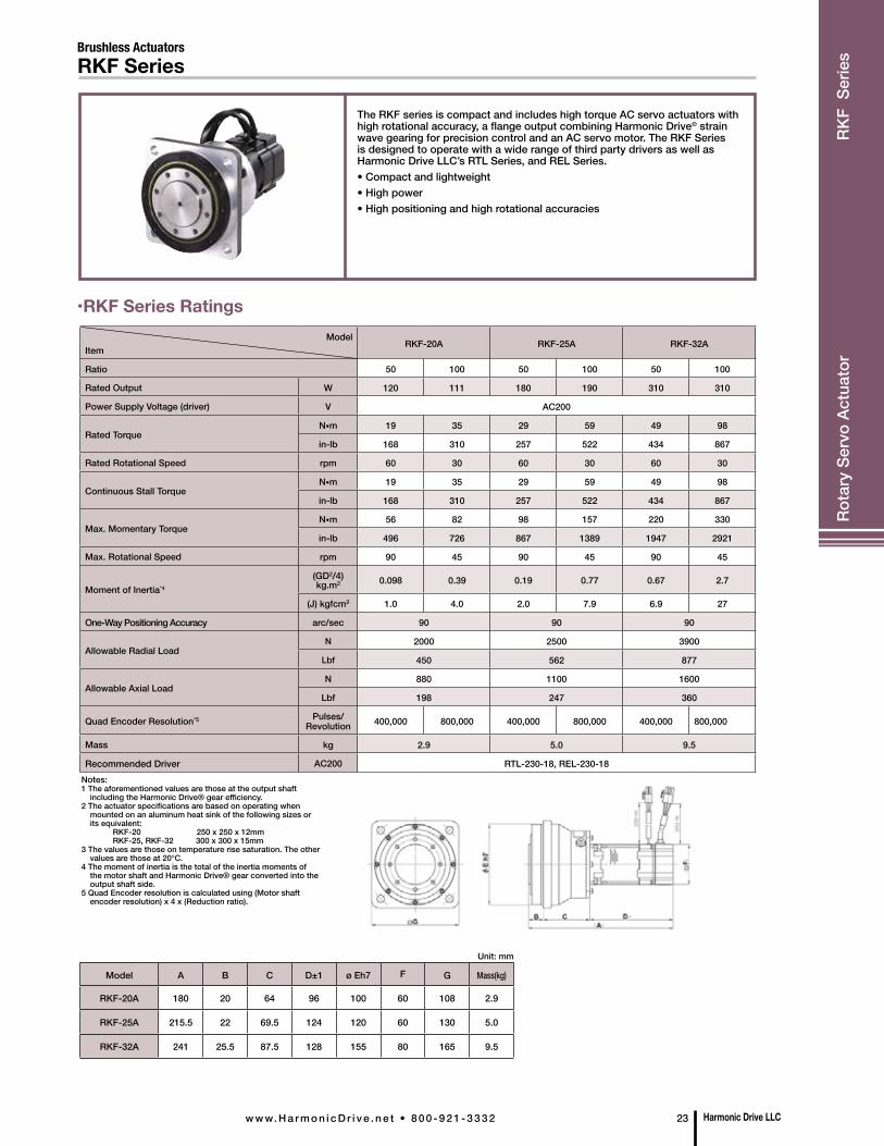
The RKF series is compact and includes high torque AC servo actuators with high rotational accuracy, a flange output combining Harmonic Drive® strain wave gearing for precision control and an AC servo motor. The RKF Series is designed to operate with a wide range of third party drivers as well as Harmonic Drive LLC’s RTL Series, and REL Series.• Compact and lightweight• High power• High positioning and high rotational accuracies
•RKF Series Ratings
RKF Series
ModelItem
RKF-20A RKF-25A RKF-32A
Ratio 50 100 50 100 50 100
Rated Output W 120 111 180 190 310 310
Power Supply Voltage (driver) V AC200
Rated TorqueN•m 19 35 29 59 49 98
in-lb 168 310 257 522 434 867
Rated Rotational Speed rpm 60 30 60 30 60 30
Continuous Stall TorqueN•m 19 35 29 59 49 98
in-lb 168 310 257 522 434 867
Max. Momentary Torque N•m 56 82 98 157 220 330
in-lb 496 726 867 1389 1947 2921
Max. Rotational Speed rpm 90 45 90 45 90 45
Moment of Inertia*4 (GD2/4) kg.m2 0.098 0.39 0.19 0.77 0.67 2.7
(J) kgfcm2 1.0 4.0 2.0 7.9 6.9 27
One-Way Positioning Accuracy arc/sec 90 90 90
Allowable Radial LoadN 2000 2500 3900
Lbf 450 562 877
Allowable Axial LoadN 880 1100 1600
Lbf 198 247 360
Quad Encoder Resolution*5 Pulses/Revolution 400,000 800,000 400,000 800,000 400,000 800,000
Mass kg 2.9 5.0 9.5
Recommended Driver AC200 RTL-230-18, REL-230-18Notes:1 The aforementioned values are those at the output shaft including the Harmonic Drive® gear efficiency.2 The actuator specifications are based on operating when mounted on an aluminum heat sink of the following sizes or its equivalent: RKF-20 250 x 250 x 12mm RKF-25, RKF-32 300 x 300 x 15mm 3 The values are those on temperature rise saturation. The other values are those at 20°C. 4 The moment of inertia is the total of the inertia moments of the motor shaft and Harmonic Drive® gear converted into the output shaft side.5 Quad Encoder resolution is calculated using (Motor shaft encoder resolution) x 4 x (Reduction ratio).
Model A B C D±1 ø Eh7 F G Mass(kg)
RKF-20A 180 20 64 96 100 60 108 2.9
RKF-25A 215.5 22 69.5 124 120 60 130 5.0
RKF-32A 241 25.5 87.5 128 155 80 165 9.5
Unit: mm
Hea
der
Rota
ry S
ervo
Act
uato
r R
KF S
erie
s
Model
Item
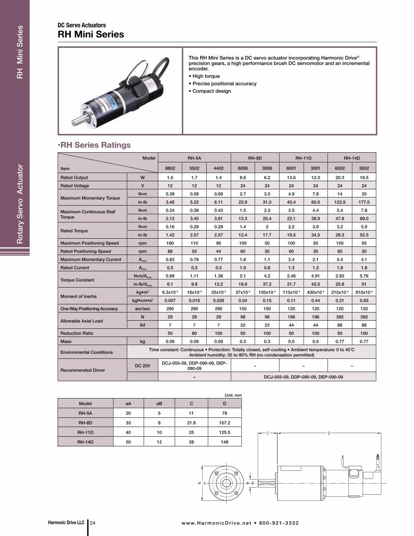
RH-5A RH-8D RH-11D RH-14D
8802 5502 4402 6006 3006 6001 3001 6002 3002
Rated Output W 1.5 1.7 1.4 8.6 6.2 13.6 12.3 20.3 18.5
Rated Voltage V 12 12 12 24 24 24 24 24 24
Maximum Momentary TorqueN•m 0.39 0.59 0.69 2.7 3.5 4.9 7.8 14 20
in-lb 3.45 5.22 6.11 23.9 31.0 43.4 60.0 123.9 177.0
Maximum Continuous Stall Torque
N•m 0.24 0.39 0.43 1.5 2.3 2.5 4.4 5.4 7.8
in-lb 2.12 3.45 3.81 13.3 20.4 22.1 38.9 47.8 69.0
Rated TorqueN•m 0.16 0.29 0.29 1.4 2 2.2 3.9 3.2 5.9
in-lb 1.42 2.57 2.57 12.4 17.7 19.5 34.5 28.3 52.5
Maximum Positioning Speed rpm 180 110 90 100 50 100 50 100 50
Rated Positioning Speed rpm 88 55 44 60 30 60 30 60 30
Maximum Momentary Current Arms 0.83 0.78 0.77 1.6 1.1 2.4 2.1 5.4 4.1
Rated Current Arms 0.5 0.5 0.5 1.0 0.8 1.3 1.3 1.8 1.8
Torque ConstantN•m/Arms 0.69 1.11 1.38 2.1 4.2 2.46 4.91 2.92 5.76
in-lb/Arms 6.1 9.8 12.2 18.6 37.2 21.7 43.5 25.8 51
Moment of Inertiakg•m2 6.3x10⁻⁴ 16x10-4 25x10-4 37x10-4 150x10-4 110x10-4 430x10-4 210x10-4 810x10-4
kgf•cm•s2 0.007 0.016 0.026 0.04 0.15 0.11 0.44 0.21 0.83
One-Way Positioning Accuracy arc/sec 290 290 290 150 150 120 120 120 120
Allowable Axial LoadN 29 29 29 98 98 196 196 392 392
lbf 7 7 7 22 22 44 44 88 88
Reduction Ratio 50 80 100 50 100 50 100 50 100
Mass kg 0.09 0.09 0.09 0.3 0.3 0.5 0.5 0.77 0.77
Environmental Conditions Time constant: Continuous • Protection: Totally closed, self-cooling • Ambient temperature: 0 to 40˚C Ambient humidity: 35 to 80% RH (no condensation permitted)
Recommended DriverDC 20V DCJ-055-09, DDP-090-09, DEP-
090-09 – – –
– DCJ-055-09, DDP-090-09, DEP-090-09
This RH Mini Series is a DC servo actuator incorporating Harmonic Drive® precision gears, a high performance brush DC servomotor and an incremental encoder.• High torque• Precise positional accuracy• Compact design
DC Servo ActuatorsRH Mini Series
•RH Series Ratings
Model øA øB C D
RH-5A 20 5 11 78
RH-8D 33 8 21.8 107.2
RH-11D 40 10 25 125.5
RH-14D 50 12 28 148
Unit: mm
Harmonic Drive LLC 24 w w w. H a r m o n i c D r i v e . n e t • 8 0 0 - 9 2 1 - 3 3 3 2
Rota
ry S
ervo
Act
uato
r R
H M
ini S
erie
s

Model HA-770-2
Rated Current 1.8A
Maximum Current 10A
Power Source Voltage AC100V~115V(Single-phase) + 10%~–15% 50/60Hz, AC200V~230V (Single-phase) + 10%~–15% 50/60Hz
Position Command Pulse
Line driver system: Maximum response frequency, Two-pulse system, One-pulse system: 1MHz,
Two-phase pulse system: 200kHz
Control System Sine wave PWM system, switching frequency: 25kHz
Control Mode Position control
Weight 0.8kg
Dire
ct D
rive
Mot
or
KDU
Ser
ies
•KDU Series Ratings
The KDU Series are Direct Drive Motors which achieve 10 arc-sec positioning accuracy as well as ±0.5 arc-sec repeatability with a resolution of 0.16 arc-sec.Also, the KDU has a large Hollow Shaft design which allows cables, shafts or lasers to pass through the axis of rotation.• Exceptional positional accuracy• Exceptional repeatability• Ultra high resolution
ModelItem
KDU-13SB KDU-13WB
Maximum Torque*2 N•m 7.0Nm (62.0 In.lb) 15.0Nm (132.8 In.lb)
Max. Rotational Speed rpm 127 127
Torque Constant N•m/Arms 3.1 (26.9 In.lb/A(rms)) 6.5 (56.4 In.lb/A(rms))
Input Power Supply Voltage V AC 100/AC200
Moment of Inertia kg.m2 0.0047 0.0065
Moment Stiffness N•m/rad 2.4 x 10⁵
Motor Position Sensor pulse/revIncremental encoder
Square wave : phase A and B: 11,840,000 Z Index Pulse Signal
Repeatability*3 arc sec ± 0.5
Absolute Positioning Accuracy*4 arc sec 10 (Angular position corrected)
Mass kg 4.0 5.0
Mounting Direction – Output shaft to face upward
Combined Driver – HA-770-2
Induced Voltage Constant V/ (rpm) .033 0.68
Line Resistance W (20°C) 9.1 14.0
Line Inductance mH 19 35
Motor Insulation – Insulation Resistance: 100 M W more (DC500V) Insulation Strength: AC1500V/1min.
Insulation Class: Class B
Protective Structure*5 – Total-enclosed self-enclosed type (IP 40 or equivalent)1 The table above shows output values of output shaft.2 The values in the table above are obtained when connected to HA-770 servo driver.3 The repeatability and absolute repeatability are the values measured in an environment of 23 ±0.3°C in temperature, 50% RH in humidity and with output shaft facing upward in mounting direction. Please contact Harmonic Drive LLC, to inquire about use with different environmental conditions.4 Value after angular position of the HA-770 servo driver is corrected.5 All parts, except the rotary sliding parts (oil seal), of the actuators are protected against solid bodies of superior dimensions to 1mm, and against the water sprays.
KDU SeriesDirect Drive Motor
•Direct Drive Motor HA-770 Series
HA-770 Series
KDU-13SB KDU-13WB
A 80 94
•Motor Length Unit: mm
Harmonic Drive LLCw w w. H a r m o n i c D r i v e . n e t • 8 0 0 - 9 2 1 - 3 3 3 2 25
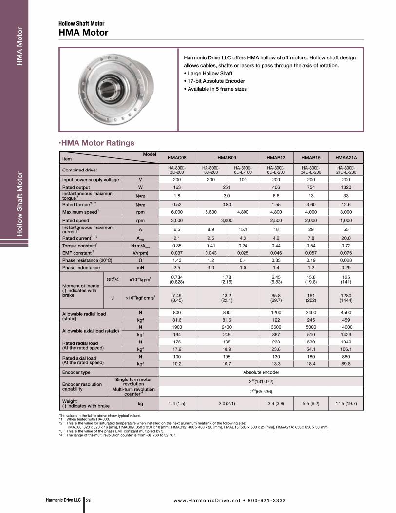
Harmonic Drive LLC offers HMA hollow shaft motors. Hollow shaft design allows cables, shafts or lasers to pass through the axis of rotation.• Large Hollow Shaft• 17-bit Absolute Encoder• Available in 5 frame sizes
Hollow Shaft MotorHMA Motor
•HMA Motor RatingsModel
Item HMAC08 HMAB09 HMAB12 HMAB15 HMAA21A
Combined driver HA-800-3D-200
HA-800-3D-200
HA-800-6D-E-100
HA-800-6D-E-200
HA-800-24D-E-200
HA-800-24D-E-200
Input power supply voltage V 200 200 100 200 200 200Rated output W 163 251 406 754 1320Instantaneous maximum torque*1 N•m 1.8 3.0 6.6 13 33
Rated torque*1, *2 N•m 0.52 0.80 1.55 3.60 12.6Maximum speed*1 rpm 6,000 5,600 4,800 4,800 4,000 3,000
Rated speed rpm 3,000 3,000 2,500 2,000 1,000Instantaneous maximum current*1 A 6.5 8.9 15.4 18 29 55
Rated current*1, *2 Arms 2.1 2.5 4.3 4.2 7.8 20.0Torque constant1 N•m/Arms 0.35 0.41 0.24 0.44 0.54 0.72EMF constant*3 V/(rpm) 0.037 0.043 0.025 0.046 0.057 0.075Phase resistance (20°C) Ω 1.43 1.2 0.4 0.33 0.19 0.028Phase inductance mH 2.5 3.0 1.0 1.4 1.2 0.29
Moment of Inertia( ) indicates with brake
GD2/4 ×10-4kg·m2 0.734(0.828)
1.78(2.16)
6.45(6.83)
15.8(19.8)
125(141)
J ×10-4kgf·cm·s2 7.49(8.45)
18.2(22.1)
65.8(69.7)
161(202)
1280(1444)
Allowable radial load (static)
N 800 800 1200 2400 4500kgf 81.6 81.6 122 245 459
Allowable axial load (static)N 1900 2400 3600 5000 14000
kgf 194 245 367 510 1429
Rated radial load(At the rated speed)
N 175 185 233 530 1040kgf 17.9 18.9 23.8 54.1 106.1
Rated axial load(At the rated speed)
N 100 105 130 180 880kgf 10.2 10.7 13.3 18.4 89.8
Encoder type Absolute encoder
Encoder resolution capability
Single turn motor revolution 217(131,072)
Multi-turn revolution counter*4 216(65,536)
Weight( ) indicates with brake kg 1.4 (1.5) 2.0 (2.1) 3.4 (3.8) 5.5 (6.2) 17.5 (19.7)
The values in the table above show typical values.*1: When tested with HA-800.*2: This is the value for saturated temperature when installed on the next aluminum heatsink of the following size:
HMAC08: 320 x 320 x 16 [mm], HMAB09: 350 x 350 x 18 [mm], HMAB12: 400 x 400 x 20 [mm], HMAB15: 500 x 500 x 25 [mm], HMAA21A: 650 x 650 x 30 [mm]*3: This is the value of the phase EMF constant multiplied by 3.*4: The range of the multi revolution counter is from -32,768 to 32,767.
Harmonic Drive LLC 26 w w w. H a r m o n i c D r i v e . n e t • 8 0 0 - 9 2 1 - 3 3 3 2
Hol
low
Sha
ft M
otor
H
MA
Mot
or
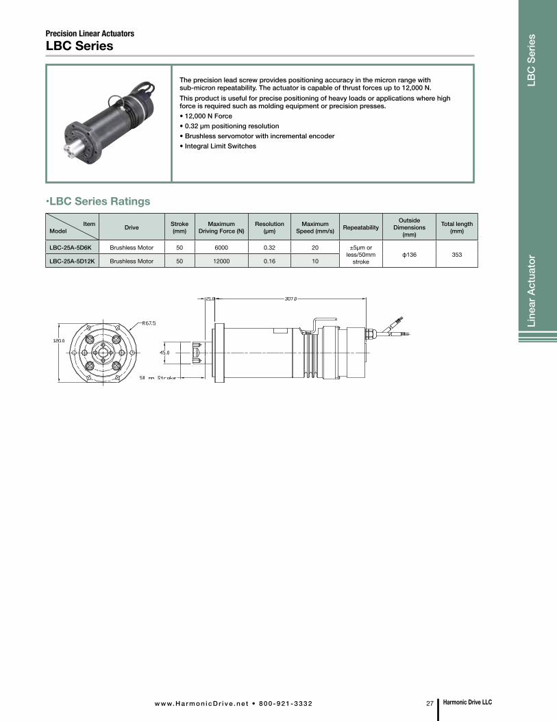
ItemModel Drive Stroke
(mm)Maximum
Driving Force (N)Resolution
(µm)Maximum
Speed (mm/s) RepeatabilityOutside
Dimensions (mm)
Total length (mm)
LBC-25A-5D6K Brushless Motor 50 6000 0.32 20 ±5µm or less/50mm
strokeφ136 353
LBC-25A-5D12K Brushless Motor 50 12000 0.16 10
Precision Linear ActuatorsLBC Series
•LBC Series Ratings
The precision lead screw provides positioning accuracy in the micron range with sub-micron repeatability. The actuator is capable of thrust forces up to 12,000 N. This product is useful for precise positioning of heavy loads or applications where high force is required such as molding equipment or precision presses.• 12,000 N Force• 0.32 µm positioning resolution• Brushless servomotor with incremental encoder• Integral Limit Switches
Harmonic Drive LLCw w w. H a r m o n i c D r i v e . n e t • 8 0 0 - 9 2 1 - 3 3 3 2 27
Line
ar A
ctua
tor
LBC
Ser
ies
Unit: mm
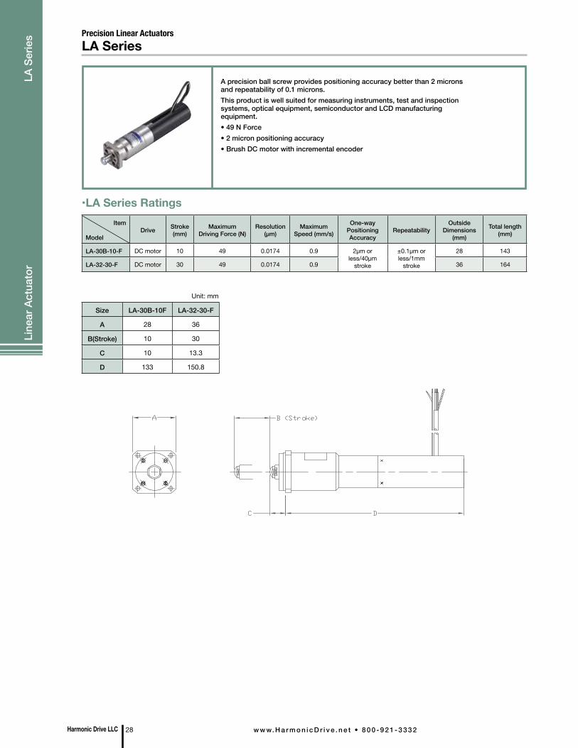
Size LA-30B-10F LA-32-30-F
A 28 36
B(Stroke) 10 30
C 10 13.3
D 133 150.8
A precision ball screw provides positioning accuracy better than 2 microns and repeatability of 0.1 microns. This product is well suited for measuring instruments, test and inspection systems, optical equipment, semiconductor and LCD manufacturing equipment.• 49 N Force• 2 micron positioning accuracy • Brush DC motor with incremental encoder
Precision Linear ActuatorsLA Series
Item
ModelDrive Stroke
(mm)Maximum
Driving Force (N)Resolution
(µm)Maximum
Speed (mm/s)
One-way Positioning Accuracy
RepeatabilityOutside
Dimensions (mm)
Total length (mm)
LA-30B-10-F DC motor 10 49 0.0174 0.9 2µm or less/40µm
stroke
±0.1µm or less/1mm
stroke
28 143
LA-32-30-F DC motor 30 49 0.0174 0.9 36 164
•LA Series Ratings
Harmonic Drive LLC 28 w w w. H a r m o n i c D r i v e . n e t • 8 0 0 - 9 2 1 - 3 3 3 2
Line
ar A
ctua
tor
LA
Serie
s
Unit: mm
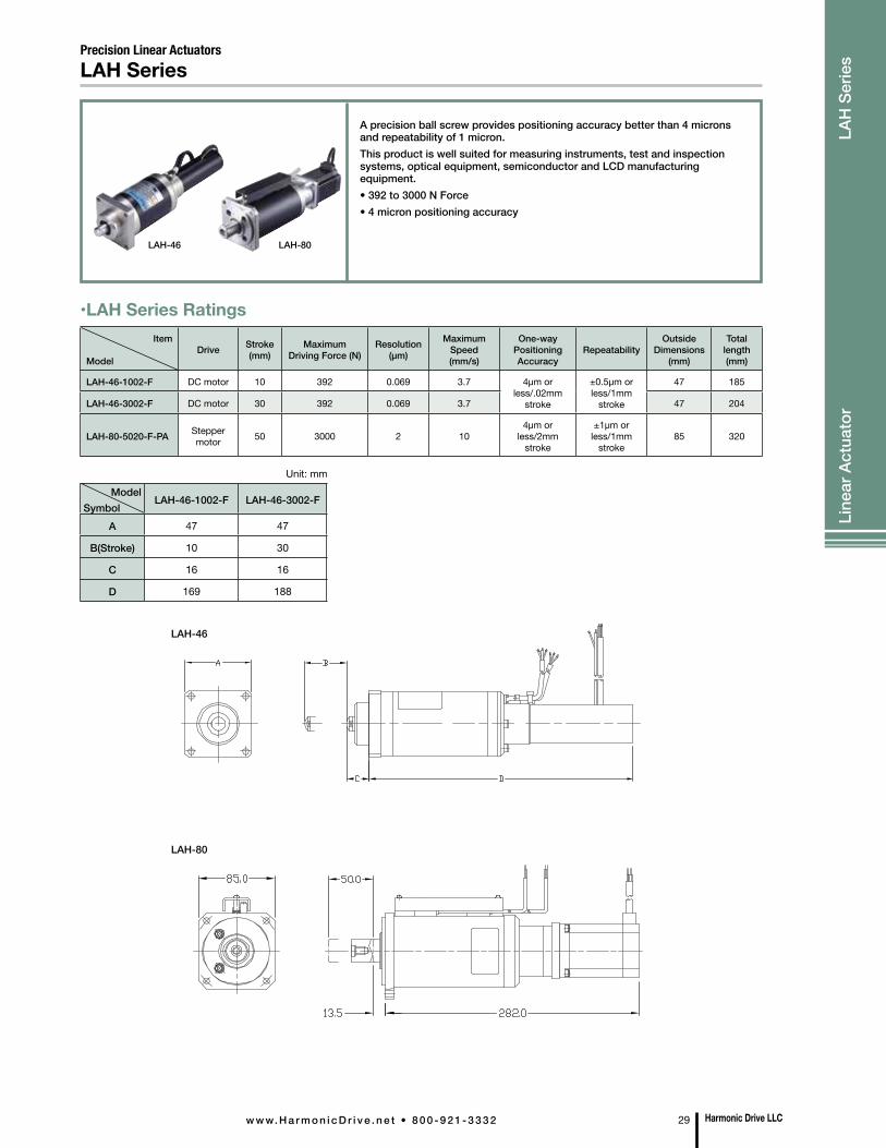
ModelSymbol
LAH-46-1002-F LAH-46-3002-F
A 47 47
B(Stroke) 10 30
C 16 16
D 169 188
LAH SeriesPrecision Linear Actuators
Item
ModelDrive Stroke
(mm)Maximum
Driving Force (N)Resolution
(µm)
Maximum Speed (mm/s)
One-way Positioning Accuracy
RepeatabilityOutside
Dimensions (mm)
Total length (mm)
LAH-46-1002-F DC motor 10 392 0.069 3.7 4µm or less/.02mm
stroke
±0.5µm or less/1mm
stroke
47 185
LAH-46-3002-F DC motor 30 392 0.069 3.7 47 204
LAH-80-5020-F-PA Stepper motor 50 3000 2 10
4µm or less/2mm
stroke
±1µm or less/1mm
stroke85 320
•LAH Series Ratings
A precision ball screw provides positioning accuracy better than 4 microns and repeatability of 1 micron. This product is well suited for measuring instruments, test and inspection systems, optical equipment, semiconductor and LCD manufacturing equipment.• 392 to 3000 N Force• 4 micron positioning accuracy
LAH-80
LAH-46
LAH-46 LAH-80
Harmonic Drive LLCw w w. H a r m o n i c D r i v e . n e t • 8 0 0 - 9 2 1 - 3 3 3 2 29
Line
ar A
ctua
tor
LAH
Ser
ies
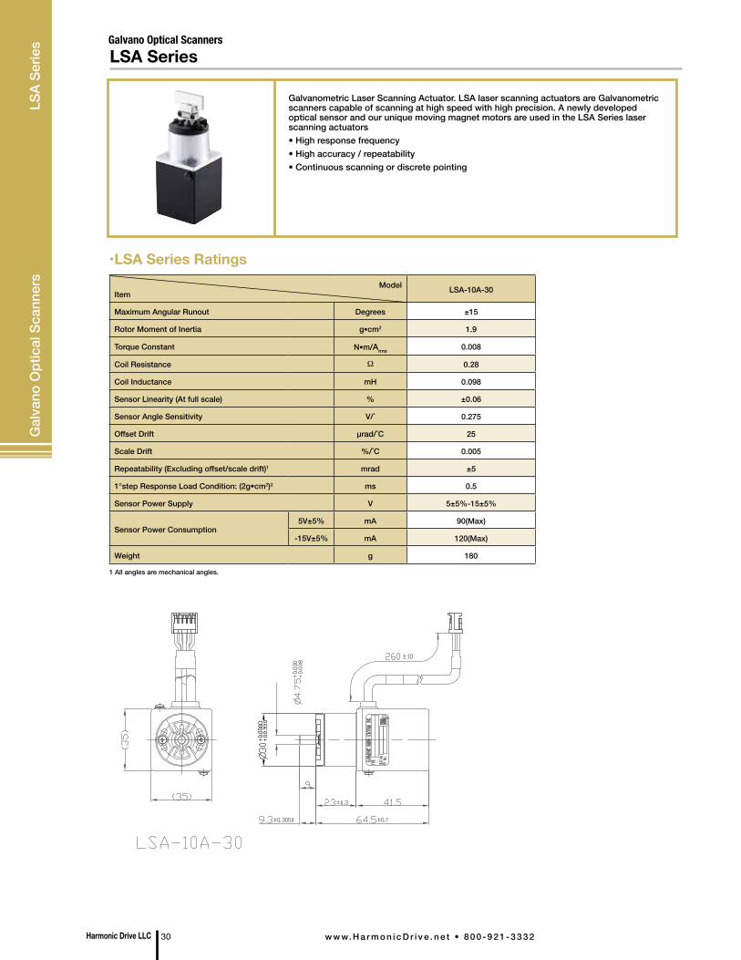
ModelItem LSA-10A-30
Maximum Angular Runout Degrees ±15
Rotor Moment of Inertia g•cm2 1.9
Torque Constant N•m/Arms 0.008
Coil Resistance Ω 0.28
Coil Inductance mH 0.098
Sensor Linearity (At full scale) % ±0.06
Sensor Angle Sensitivity V/˚ 0.275
Offset Drift µrad/˚C 25
Scale Drift %/˚C 0.005
Repeatability (Excluding offset/scale drift)1 mrad ±5
1°step Response Load Condition: (2g•cm2)2 ms 0.5
Sensor Power Supply V 5±5%-15±5%
Sensor Power Consumption5V±5% mA 90(Max)
-15V±5% mA 120(Max)
Weight g 180
•LSA Series Ratings
1 All angles are mechanical angles.
Galvano Optical ScannersLSA Series
Galvanometric Laser Scanning Actuator. LSA laser scanning actuators are Galvanometric scanners capable of scanning at high speed with high precision. A newly developed optical sensor and our unique moving magnet motors are used in the LSA Series laser scanning actuators• High response frequency• High accuracy / repeatability• Continuous scanning or discrete pointing
Harmonic Drive LLC 30 w w w. H a r m o n i c D r i v e . n e t • 8 0 0 - 9 2 1 - 3 3 3 2
Gal
vano
Opt
ical
Sca
nner
s LS
A Se
ries
ModelItem
MES-6- PC Number of Pulses
ME -9- PC
Power Supply DC5V±10% DC5V±10%
Current Consumption 30mA or less (under no load) 40mA or less (under no load)
Detection System Incremental Incremental
Number of Output Pulses (Standard) [Number of Pulses/Number of Revolutions] 100 200 300 360 100 200 300 360 500 1000
Output Phases A, B and Z phases A, B and Z phases
Output Mode Square wave, open collector output Square wave, open collector output
Maximum Response Frequency(Number of Response Pulses) 100kHz 100kHz
Output Phase DifferenceDifference between A and B Phases 90˚±45˚
(T/4±T/8), Z PhaseT±T/2 (See output waveform diagram.)
Difference between A and B Phases 90˚±45˚ (T/4±T/8), Z PhaseT±T/2 (See output waveform
diagram.)
Permissible Maximum Positioning Speed (Mechanical) 6000rpm 6000rpm
Operating Temperature and Humidity 0˚C~60˚C RH 35%~90% No condensation permitted
0˚C~60˚C RH 35%~90% No condensation permitted
Storage Ambient Temperature -20˚C~80˚C -20˚C~80˚C
Weight 5g 10g
•Micro Encoder Series Ratings
•Model Ordering Code
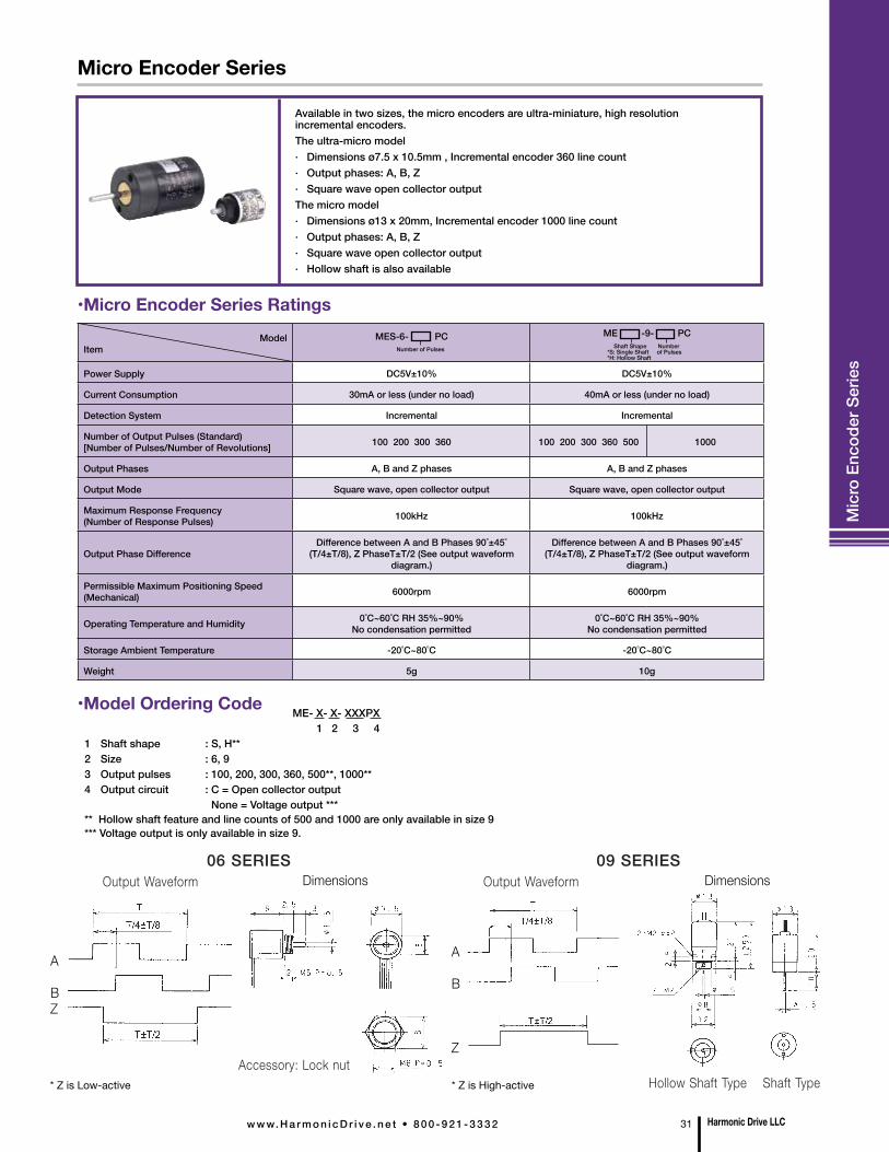
Micro Encoder Series
Mic
ro E
ncod
er S
erie
s
Available in two sizes, the micro encoders are ultra-miniature, high resolution incremental encoders. The ultra-micro model· Dimensions ø7.5 x 10.5mm , Incremental encoder 360 line count· Output phases: A, B, Z· Square wave open collector outputThe micro model· Dimensions ø13 x 20mm, Incremental encoder 1000 line count· Output phases: A, B, Z· Square wave open collector output· Hollow shaft is also available
06 SERIES 09 SERIES Output Waveform Appearance Output Waveform Appearance
Accessory: Lock nut Hollow Shaft Type Shaft Type
Shaft Shape Number *S: Single Shaft of Pulses *H: Hollow Shaft
DimensionsDimensions
ME- X- X- XXXPX 1 2 3 4 1 Shaft shape : S, H** 2 Size : 6, 93 Output pulses : 100, 200, 300, 360, 500**, 1000** 4 Output circuit : C = Open collector output None = Voltage output ***** Hollow shaft feature and line counts of 500 and 1000 are only available in size 9*** Voltage output is only available in size 9.
A
BZ
A
B
Z
* Z is Low-active * Z is High-active
Harmonic Drive LLCw w w. H a r m o n i c D r i v e . n e t • 8 0 0 - 9 2 1 - 3 3 3 2 31
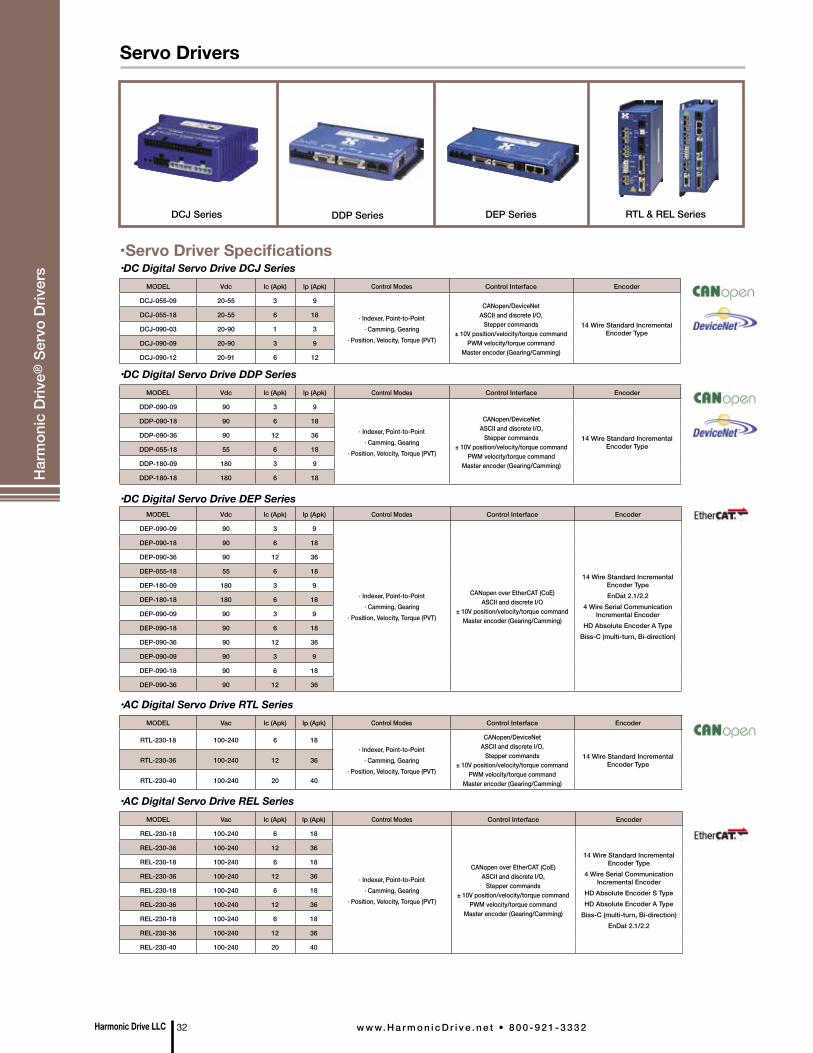
•Servo Driver Specifications
DEP SeriesDCJ Series RTL & REL SeriesDDP Series
•DC Digital Servo Drive DCJ Series
•AC Digital Servo Drive RTL Series
•DC Digital Servo Drive DDP Series
•DC Digital Servo Drive DEP Series
•AC Digital Servo Drive REL Series
MODEL Vdc lc (Apk) lp (Apk) Control Modes Control Interface Encoder
DCJ-055-09 20-55 3 9
· Indexer, Point-to-Point · Camming, Gearing
· Position, Velocity, Torque (PVT)
CANopen/DeviceNet ASCII and discrete I/O,
Stepper commands ± 10V position/velocity/torque command
PWM velocity/torque command Master encoder (Gearing/Camming)
14 Wire Standard Incremental Encoder Type
DCJ-055-18 20-55 6 18
DCJ-090-03 20-90 1 3
DCJ-090-09 20-90 3 9
DCJ-090-12 20-91 6 12
MODEL Vac lc (Apk) lp (Apk) Control Modes Control Interface Encoder
RTL-230-18 100-240 6 18· Indexer, Point-to-Point
· Camming, Gearing· Position, Velocity, Torque (PVT)
CANopen/DeviceNet ASCII and discrete I/O,
Stepper commands ± 10V position/velocity/torque command
PWM velocity/torque command Master encoder (Gearing/Camming)
14 Wire Standard Incremental Encoder TypeRTL-230-36 100-240 12 36
RTL-230-40 100-240 20 40
MODEL Vdc lc (Apk) lp (Apk) Control Modes Control Interface Encoder
DDP-090-09 90 3 9
· Indexer, Point-to-Point · Camming, Gearing
· Position, Velocity, Torque (PVT)
CANopen/DeviceNet ASCII and discrete I/O,
Stepper commands ± 10V position/velocity/torque command
PWM velocity/torque command Master encoder (Gearing/Camming)
14 Wire Standard Incremental Encoder Type
DDP-090-18 90 6 18
DDP-090-36 90 12 36
DDP-055-18 55 6 18
DDP-180-09 180 3 9
DDP-180-18 180 6 18
MODEL Vdc lc (Apk) lp (Apk) Control Modes Control Interface Encoder
DEP-090-09 90 3 9
· Indexer, Point-to-Point · Camming, Gearing
· Position, Velocity, Torque (PVT)
CANopen over EtherCAT (CoE) ASCII and discrete I/O
± 10V position/velocity/torque command Master encoder (Gearing/Camming)
14 Wire Standard Incremental Encoder TypeEnDat 2.1/2.2
4 Wire Serial Communication Incremental Encoder
HD Absolute Encoder A TypeBiss-C (multi-turn, Bi-direction)
DEP-090-18 90 6 18
DEP-090-36 90 12 36
DEP-055-18 55 6 18
DEP-180-09 180 3 9
DEP-180-18 180 6 18
DEP-090-09 90 3 9
DEP-090-18 90 6 18
DEP-090-36 90 12 36
DEP-090-09 90 3 9
DEP-090-18 90 6 18
DEP-090-36 90 12 36
MODEL Vac lc (Apk) lp (Apk) Control Modes Control Interface Encoder
REL-230-18 100-240 6 18
· Indexer, Point-to-Point · Camming, Gearing
· Position, Velocity, Torque (PVT)
CANopen over EtherCAT (CoE) ASCII and discrete I/O,
Stepper commands ± 10V position/velocity/torque command
PWM velocity/torque command Master encoder (Gearing/Camming)
14 Wire Standard Incremental Encoder Type
4 Wire Serial Communication Incremental Encoder
HD Absolute Encoder S TypeHD Absolute Encoder A Type
Biss-C (multi-turn, Bi-direction)EnDat 2.1/2.2
REL-230-36 100-240 12 36
REL-230-18 100-240 6 18
REL-230-36 100-240 12 36
REL-230-18 100-240 6 18
REL-230-36 100-240 12 36
REL-230-18 100-240 6 18
REL-230-36 100-240 12 36
REL-230-40 100-240 20 40
Harmonic Drive LLC 32 w w w. H a r m o n i c D r i v e . n e t • 8 0 0 - 9 2 1 - 3 3 3 2
Servo DriversH
arm
onic
Driv
e® S
ervo
Driv
ers

Harmonic Drive LLCw w w. H a r m o n i c D r i v e . n e t • 8 0 0 - 9 2 1 - 3 3 3 2 33
•DC Digital Servo Drive DCJ SeriesMODEL Vdc lc (Apk) lp (Apk) Supply Voltage Combination Actuator
DCJ-055-09 20-55 3 9
DC24V
FHA-8C-30 / 50 / 100-US200-E, RSF-8B-30 / 50 / 100-F100-24B, RSF-5A-30 / 50 / 100-US050, RSF-3B-30 / 50 / 100-US020
DCJ-055-18 20-55 6 18 FHA-11C-30 / 50 / 100-US200-E
DCJ-090-03 20-90 1 3 –
DCJ-090-09 20-90 3 9 –
DCJ-090-12 20-90 6 12 –
•DC Digital Servo Drive DDP SeriesMODEL Vdc lc (Apk) lp (Apk) Supply Voltage Combination Actuator
DDP-090-09 90 3 9
DC24V
FHA-8C-30 / 50 / 100-US200-E, RSF-8B-30 / 50 / 100-F100-24B, RSF-5A-30 / 50 / 100-US050, RSF-3B-30 / 50 / 100-US020
DDP-090-18 90 6 18 FHA-11C-30 / 50 / 100-US200-E
DDP-090-36 90 12 36 FHA-14C-30 / 50 / 100-US200-E, FHA-17C50* / 100 / 160-US250-E-SP, RSF-14B-30 / 50 / 100-F100-24B, RSF-11B-30 / 50 / 100-F100-24B
DDP-055-18 55 6 18 –
DDP-180-09 180 3 9 –
DDP-180-18 180 6 18 –
•DC Digital Servo Drive DEP SeriesMODEL Vdc lc (Apk) lp (Apk) Supply Voltage Combination Actuator
DEP-090-09 90 3 9
DC24V
FHA-8C-30 / 50 / 100-US200 / 12S176b / E200, RSF-8B-30 / 50 / 100-F100-24B, RSF-5A-30 / 50 / 100-US050, RSF-3B-30 / 50 / 100-US020
DEP-090-18 90 6 18 FHA-11C-30 / 50 / 100-US200 / 12S176b / E200
DEP-090-36 90 12 36FHA-14C-30 / 50 / 100-US200 / 12S176b / E200, FHA-17C50* / 100* /
160-US250 / E250 / S248, RSF-14B-30 / 50 / 100-F100-24B, RSF-11B-30 / 50 / 100-F100-24B
MODEL Vac lc (Apk) lp (Apk) Supply Voltage Combination Actuator
REL-230-18 100-240 6 18
AC100/200V FHA-8C-30 / 50 / 100-US200 / 12S17b / E200, FHA-11C-30 / 50 / 100-US200 / 12S17b / E200, FHA-14C-30 / 50 / 100-US200 / 12S17b / E200
AC100V FHA-17C-50 / 100 / 160-US250 / E250 / S248, FHA-25C-100 / 160-US250 / E250 / S248, FHA-32C-160-US250 / E250 / S248
AC200VFHA-17C-50 / 100 / 160-US250 / E250 / S248, FHA-25C-50 / 100 / 160-US250 / E250 / S248, FHA-32C-50 / 100 / 160-US250 / E250 / S248, FHA-40C-100 /
160-US250 / E250 / S248
REL-230-36 100-240 12 36AC100V FHA-25C-50-US250 / E250 / S248, FHA-32C-50 / 100-US250 / E250 / S248
AC200V FHA-40C-50-US250 / E250 / S248
REL-230-18 100-240 6 18
AC200V
SHA-20SG-51 / 81 / 101 / 121 / 161, SHA-20CG-50 / 80 / 100 / 120 / 160, SHA-25SG-51 / 81 / 101 / 121 / 161, SHA-25CG-50 / 80 / 100 / 120 / 160,
SHA-32SG-161, SHA-32CG-160
REL-230-36 100-240 12 36 SHA-32SG-51 / 81 / 101 / 121, SHA-32CG-50 / 80 / 100 / 120, SHA-40SG-121 / 161, SHA-40CG-120 / 160
REL-230-40 100-240 20 40 SHA-40SG-51 /81 /101, SHA-40CG-50 /80 /100
•AC Digital Servo Drive RTL SeriesMODEL Vac lc (Apk) lp (Apk) Supply Voltage Combination Actuator
RTL-230-18 100-240 6 18
AC100/200V FHA-8C-30 / 50 / 100-US200 / 12S176b / E200, FHA-11C-30 / 50 / 100-US200 / 12S176b / E200, FHA-14C-30 / 50 / 100-US200 / 12S176 / E200
AC100V FHA-17C-50 / 100 / 160-US250 / E250 / S248, FHA-25C-100 / 160-US250 / E250 / S248, FHA-32C-160-US250 / E250 / S248
AC200VFHA-17C-50 / 100 / 160-US250 / E250 / S248, FHA-25C-100 / 160-US250 /
E250 / S248, FHA-32C-160-US250 / E250 / S248, FHA-40C-100 / 160-US250 / E250 / S248
RTL-230-36 100-240 12 36AC100V FHA-25C-50-US250 / E250 / S248, FHA-32C-50 / 100-US250 / E250 / S248
AC200V FHA-40C-50-US250 / E250 / S248
RTL-230-40 100-240 20 40 AC200V –
•AC Digital Servo Drive REL Series
Recommended Driver•Combinations with Servo Drive and Actuator
Har
mon
ic D
rive®
Ser
vo D
river
s
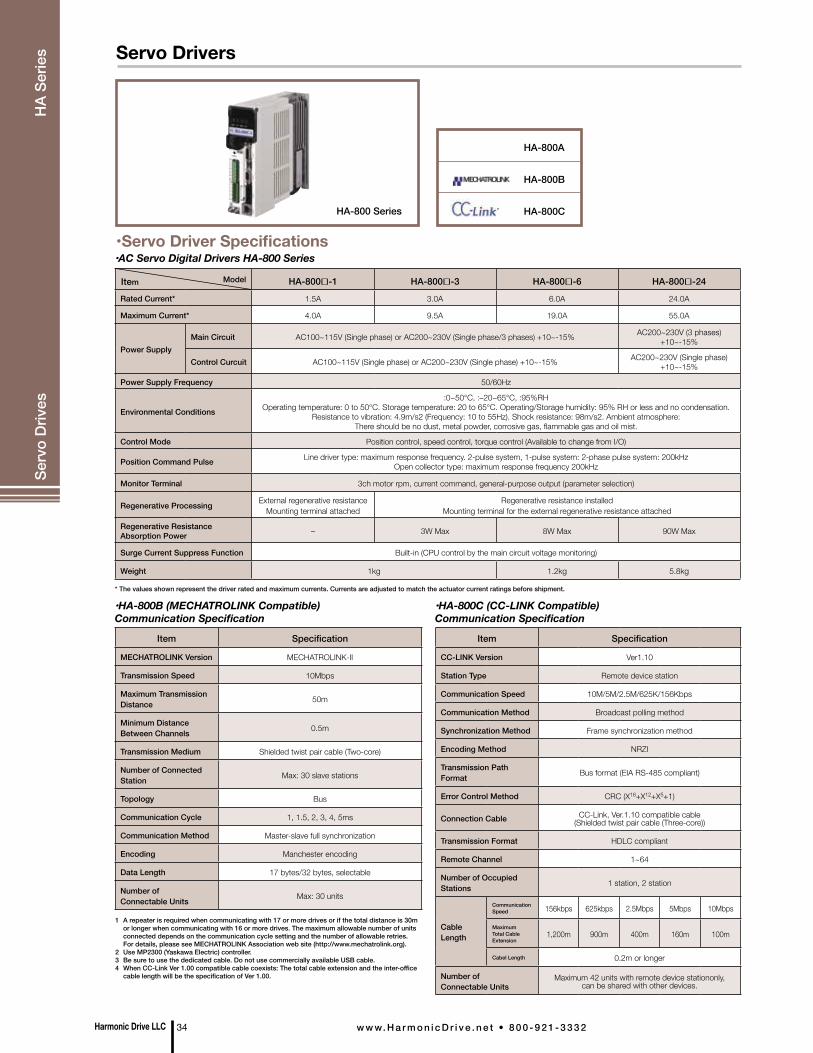
•Servo Driver Specifications
Item Model HA-800÷-1 HA-800÷-3 HA-800÷-6 HA-800÷-24
Rated Current* 1.5A 3.0A 6.0A 24.0A
Maximum Current* 4.0A 9.5A 19.0A 55.0A
Power SupplyMain Circuit AC100~115V (Single phase) or AC200~230V (Single phase/3 phases) +10~-15% AC200~230V (3 phases)
+10~-15%
Control Curcuit AC100~115V (Single phase) or AC200~230V (Single phase) +10~-15% AC200~230V (Single phase) +10~-15%
Power Supply Frequency 50/60Hz
Environmental Conditions
:0~50°C, :–20~65°C, :95%RHOperating temperature: 0 to 50°C. Storage temperature: 20 to 65°C. Operating/Storage humidity: 95% RH or less and no condensation.
Resistance to vibration: 4.9m/s2 (Frequency: 10 to 55Hz). Shock resistance: 98m/s2. Ambient atmosphere: There should be no dust, metal powder, corrosive gas, flammable gas and oil mist.
Control Mode Position control, speed control, torque control (Available to change from I/O)
Position Command Pulse Line driver type: maximum response frequency. 2-pulse system, 1-pulse system: 2-phase pulse system: 200kHzOpen collector type: maximum response frequency 200kHz
Monitor Terminal 3ch motor rpm, current command, general-purpose output (parameter selection)
Regenerative Processing External regenerative resistance Mounting terminal attached
Regenerative resistance installed Mounting terminal for the external regenerative resistance attached
Regenerative Resistance Absorption Power – 3W Max 8W Max 90W Max
Surge Current Suppress Function Built-in (CPU control by the main circuit voltage monitoring)
Weight 1kg 1.2kg 5.8kg
•AC Servo Digital Drivers HA-800 Series
HA-800 Series
HA-800A
HA-800B
HA-800C
Item Specification
MECHATROLINK Version MECHATROLINK-II
Transmission Speed 10Mbps
Maximum Transmission Distance 50m
Minimum Distance Between Channels 0.5m
Transmission Medium Shielded twist pair cable (Two-core)
Number of Connected Station Max: 30 slave stations
Topology Bus
Communication Cycle 1, 1.5, 2, 3, 4, 5ms
Communication Method Master-slave full synchronization
Encoding Manchester encoding
Data Length 17 bytes/32 bytes, selectable
Number of Connectable Units Max: 30 units
Item Specification
CC-LINK Version Ver1.10
Station Type Remote device station
Communication Speed 10M/5M/2.5M/625K/156Kbps
Communication Method Broadcast polling method
Synchronization Method Frame synchronization method
Encoding Method NRZI
Transmission Path Format Bus format (EIA RS-485 compliant)
Error Control Method CRC (X16+X12+X5+1)
Connection Cable CC-Link, Ver.1.10 compatible cable (Shielded twist pair cable (Three-core))
Transmission Format HDLC compliant
Remote Channel 1~64
Number of Occupied Stations 1 station, 2 station
Cable Length
Communication Speed 156kbps 625kbps 2.5Mbps 5Mbps 10Mbps
Maximum Total Cable Extension
1,200m 900m 400m 160m 100m
Cabel Length 0.2m or longer
Number of Connectable Units
Maximum 42 units with remote device stationonly, can be shared with other devices.
•HA-800B (MECHATROLINK Compatible) Communication Specification
•HA-800C (CC-LINK Compatible) Communication Specification
1 A repeater is required when communicating with 17 or more drives or if the total distance is 30m or longer when communicating with 16 or more drives. The maximum allowable number of units connected depends on the communication cycle setting and the number of allowable retries. For details, please see MECHATROLINK Association web site (http://www.mechatrolink.org).2 Use MP2300 (Yaskawa Electric) controller.3 Be sure to use the dedicated cable. Do not use commercially available USB cable.4 When CC-Link Ver 1.00 compatible cable coexists: The total cable extension and the inter-office cable length will be the specification of Ver 1.00.
* The values shown represent the driver rated and maximum currents. Currents are adjusted to match the actuator current ratings before shipment.
Harmonic Drive LLC 34 w w w. H a r m o n i c D r i v e . n e t • 8 0 0 - 9 2 1 - 3 3 3 2
Servo DriversSe
rvo
Driv
es
HA
Serie
s
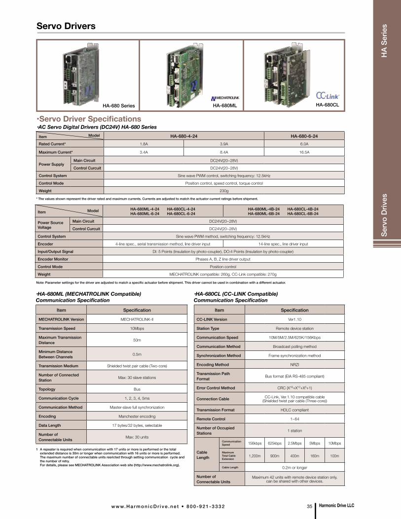
•Servo Driver Specifications•AC Servo Digital Drivers (DC24V) HA-680 Series
•AC Servo Digital Drivers (DC24V) HA-680ML/CL
Item Model HA-680-4-24 HA-680-6-24Rated Current* 1.8A 3.9A 6.0A
Maximum Current* 3.4A 8.4A 16.5A
Power SupplyMain Circuit DC24V(20~28V)
Control Curcuit DC24V(20~28V)
Control System Sine wave PWM control, switching frequency: 12.5kHz
Control Mode Position control, speed control, torque control
Weight 230g
Item Model HA-680ML-4-24 HA-680CL-4-24 HA-680ML-6-24 HA-680CL-6-24
HA-680ML-4B-24 HA-680CL-4B-24 HA-680ML-6B-24 HA-680CL-6B-24
Power Source Voltage
Main Circuit DC24V(20~28V)
Control Curcuit DC24V(20~28V)
Control System Sine wave PWM method, switching frequency: 12.5kHz
Encoder 4-line spec., serial transmission method, line driver input 14-line spec., line driver input
Input/Output Signal DI: 5 Points (Insulation by photo-coupler), DO:4 Points (Insulation by photo-coupler)
Encoder Monitor Phases A, B, Z line driver output
Control Mode Position control
Weight MECHATROLINK compatible: 260g, CC-Link compatible: 270g
HA-680ML HA-680CLHA-680 Series
Item Specification
MECHATROLINK Version MECHATROLINK-II
Transmission Speed 10Mbps
Maximum Transmission Distance 50m
Minimum Distance Between Channels 0.5m
Transmission Medium Shielded twist pair cable (Two-core)
Number of Connected Station Max: 30 slave stations
Topology Bus
Communication Cycle 1, 2, 3, 4, 5ms
Communication Method Master-slave full synchronization
Encoding Manchester encoding
Data Length 17 bytes/32 bytes, selectable
Number of Connectable Units Max: 30 units
Item Specification
CC-LINK Version Ver1.10
Station Type Remote device station
Communication Speed 10M/5M/2.5M/625K/156Kbps
Communication Method Broadcast polling method
Synchronization Method Frame synchronization method
Encoding Method NRZI
Transmission Path Format Bus format (EIA RS-485 compliant)
Error Control Method CRC (X16+X12+X5+1)
Connection Cable CC-Link, Ver.1.10 compatible cable (Shielded twist pair cable (Three-core))
Transmission Format HDLC compliant
Remote Control 1~64
Number of Occupied Stations 1 station
Cable Length
Communication Speed 156kbps 625kbps 2.5Mbps 5Mbps 10Mbps
Maximum Total Cable Extension
1,200m 900m 400m 160m 100m
Cable Length 0.2m or longer
Number of Connectable Units
Maximum 42 units with remote device station only, can be shared with other devices.
•HA-680ML (MECHATROLINK Compatible) Communication Specification
•HA-680CL (CC-LINK Compatible) Communication Specification
1 A repeater is required when communication with 17 units or more is performed or the total extended distance is 30m or longer when communication with 16 units or more is performed. The maximum number of connectable units resricted through setting communication cycle and the number of retry. For details, please see MECHATROLINK Association web site (http://www.mechatrolink.org).
* The values shown represent the driver rated and maximum currents. Currents are adjusted to match the actuator current ratings before shipment.
Note: Parameter settings for the driver are adjusted to match a specific actuator before shipment. This driver cannot be used in combination with a different actuator.
Harmonic Drive LLCw w w. H a r m o n i c D r i v e . n e t • 8 0 0 - 9 2 1 - 3 3 3 2 35
Servo Drivers
Serv
o D
rives
H
A Se
ries
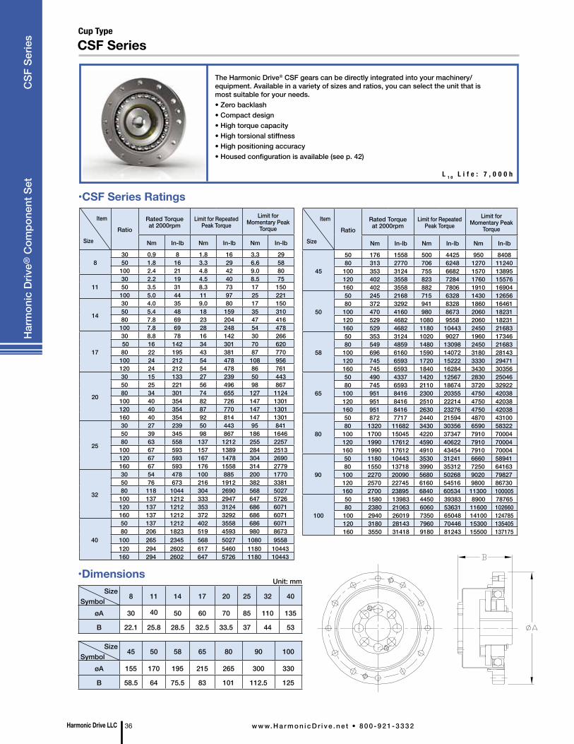
Cup Type
CSF Series
The Harmonic Drive® CSF gears can be directly integrated into your machinery/equipment. Available in a variety of sizes and ratios, you can select the unit that is most suitable for your needs.• Zero backlash• Compact design• High torque capacity• High torsional stiffness• High positioning accuracy• Housed configuration is available (see p. 42)
L 1 0 L i f e : 7 , 0 0 0 h
SizeSymbol
8 11 14 17 20 25 32 40
øA 30 40 50 60 70 85 110 135
B 22.1 25.8 28.5 32.5 33.5 37 44 53
SizeSymbol
45 50 58 65 80 90 100
øA 155 170 195 215 265 300 330
B 58.5 64 75.5 83 101 112.5 125
Unit: mm
Item
Size
RatioRated Torque at 2000rpm
Limit for Repeated Peak Torque
Limit for Momentary Peak
Torque
Nm In-lb Nm In-lb Nm In-lb
45
50 176 1558 500 4425 950 840880 313 2770 706 6248 1270 11240
100 353 3124 755 6682 1570 13895120 402 3558 823 7284 1760 15576160 402 3558 882 7806 1910 16904
50
50 245 2168 715 6328 1430 1265680 372 3292 941 8328 1860 16461
100 470 4160 980 8673 2060 18231120 529 4682 1080 9558 2060 18231160 529 4682 1180 10443 2450 21683
58
50 353 3124 1020 9027 1960 1734680 549 4859 1480 13098 2450 21683
100 696 6160 1590 14072 3180 28143120 745 6593 1720 15222 3330 29471160 745 6593 1840 16284 3430 30356
65
50 490 4337 1420 12567 2830 2504680 745 6593 2110 18674 3720 32922
100 951 8416 2300 20355 4750 42038120 951 8416 2510 22214 4750 42038160 951 8416 2630 23276 4750 42038
80
50 872 7717 2440 21594 4870 4310080 1320 11682 3430 30356 6590 58322
100 1700 15045 4220 37347 7910 70004120 1990 17612 4590 40622 7910 70004160 1990 17612 4910 43454 7910 70004
90
50 1180 10443 3530 31241 6660 5894180 1550 13718 3990 35312 7250 64163
100 2270 20090 5680 50268 9020 79827120 2570 22745 6160 54516 9800 86730160 2700 23895 6840 60534 11300 100005
100
50 1580 13983 4450 39383 8900 7876580 2380 21063 6060 53631 11600 102660100 2940 26019 7350 65048 14100 124785120 3180 28143 7960 70446 15300 135405160 3550 31418 9180 81243 15500 137175
Item
Size
RatioRated Torque at 2000rpm
Limit for Repeated Peak Torque
Limit for Momentary Peak
Torque
Nm In-lb Nm In-lb Nm In-lb
830 0.9 8 1.8 16 3.3 2950 1.8 16 3.3 29 6.6 58
100 2.4 21 4.8 42 9.0 80
1130 2.2 19 4.5 40 8.5 7550 3.5 31 8.3 73 17 150
100 5.0 44 11 97 25 221
14
30 4.0 35 9.0 80 17 15050 5.4 48 18 159 35 31080 7.8 69 23 204 47 416
100 7.8 69 28 248 54 478
17
30 8.8 78 16 142 30 266 50 16 142 34 301 70 62080 22 195 43 381 87 770
100 24 212 54 478 108 956120 24 212 54 478 86 761
20
30 15 133 27 239 50 44350 25 221 56 496 98 86780 34 301 74 655 127 1124
100 40 354 82 726 147 1301120 40 354 87 770 147 1301160 40 354 92 814 147 1301
25
30 27 239 50 443 95 84150 39 345 98 867 186 164680 63 558 137 1212 255 2257
100 67 593 157 1389 284 2513120 67 593 167 1478 304 2690160 67 593 176 1558 314 2779
32
30 54 478 100 885 200 177050 76 673 216 1912 382 338180 118 1044 304 2690 568 5027
100 137 1212 333 2947 647 5726120 137 1212 353 3124 686 6071160 137 1212 372 3292 686 6071
40
50 137 1212 402 3558 686 607180 206 1823 519 4593 980 8673
100 265 2345 568 5027 1080 9558120 294 2602 617 5460 1180 10443160 294 2602 647 5726 1180 10443
Harmonic Drive LLC 36 w w w. H a r m o n i c D r i v e . n e t • 8 0 0 - 9 2 1 - 3 3 3 2
Har
mon
ic D
rive®
Com
pone
nt S
et
CSF
Ser
ies
•CSF Series Ratings
•Dimensions
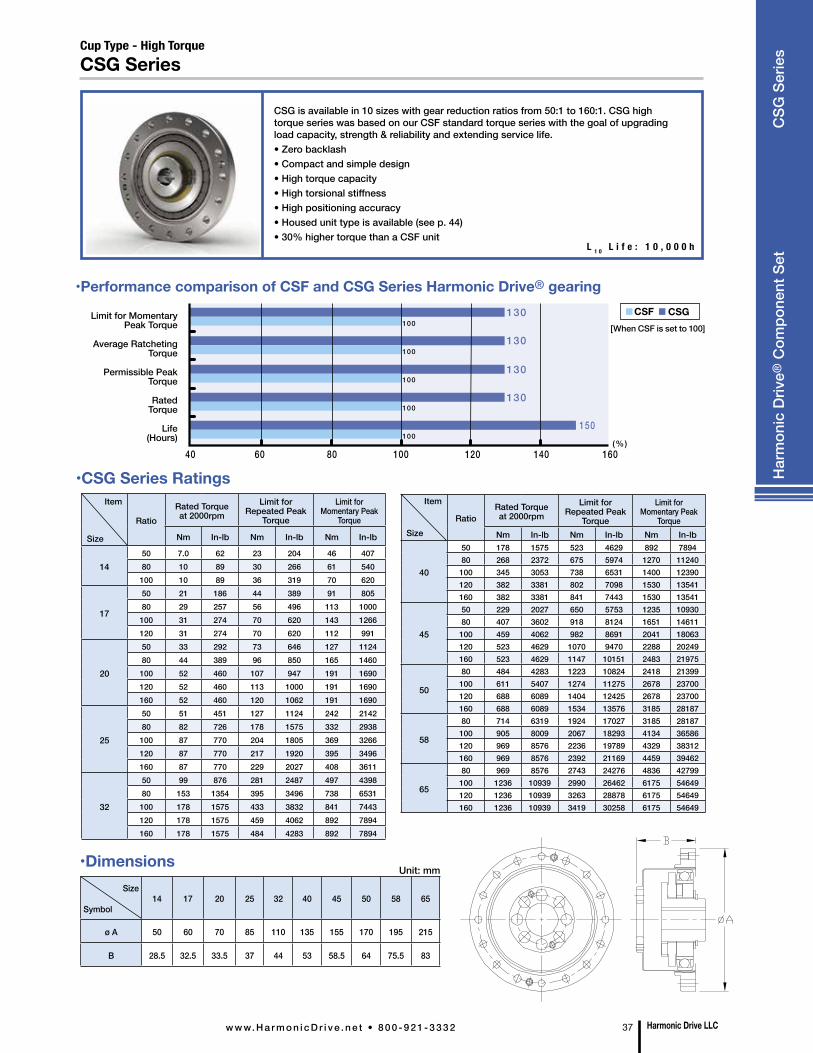
Item
Size
RatioRated Torque at 2000rpm
Limit for Repeated Peak
Torque
Limit for Momentary Peak
Torque
Nm In-lb Nm In-lb Nm In-lb
1450 7.0 62 23 204 46 40780 10 89 30 266 61 540100 10 89 36 319 70 620
17
50 21 186 44 389 91 80580 29 257 56 496 113 1000100 31 274 70 620 143 1266120 31 274 70 620 112 991
20
50 33 292 73 646 127 112480 44 389 96 850 165 1460100 52 460 107 947 191 1690120 52 460 113 1000 191 1690160 52 460 120 1062 191 1690
25
50 51 451 127 1124 242 214280 82 726 178 1575 332 2938100 87 770 204 1805 369 3266120 87 770 217 1920 395 3496160 87 770 229 2027 408 3611
32
50 99 876 281 2487 497 439880 153 1354 395 3496 738 6531100 178 1575 433 3832 841 7443120 178 1575 459 4062 892 7894160 178 1575 484 4283 892 7894
Item
SizeRatio
Rated Torque at 2000rpm
Limit for Repeated Peak
Torque
Limit for Momentary Peak
TorqueNm In-lb Nm In-lb Nm In-lb
40
50 178 1575 523 4629 892 789480 268 2372 675 5974 1270 11240
100 345 3053 738 6531 1400 12390120 382 3381 802 7098 1530 13541160 382 3381 841 7443 1530 13541
45
50 229 2027 650 5753 1235 1093080 407 3602 918 8124 1651 14611
100 459 4062 982 8691 2041 18063120 523 4629 1070 9470 2288 20249160 523 4629 1147 10151 2483 21975
50
80 484 4283 1223 10824 2418 21399100 611 5407 1274 11275 2678 23700120 688 6089 1404 12425 2678 23700160 688 6089 1534 13576 3185 28187
58
80 714 6319 1924 17027 3185 28187100 905 8009 2067 18293 4134 36586120 969 8576 2236 19789 4329 38312160 969 8576 2392 21169 4459 39462
65
80 969 8576 2743 24276 4836 42799100 1236 10939 2990 26462 6175 54649120 1236 10939 3263 28878 6175 54649160 1236 10939 3419 30258 6175 54649
Harmonic Drive LLCw w w. H a r m o n i c D r i v e . n e t • 8 0 0 - 9 2 1 - 3 3 3 2 37
Har
mon
ic D
rive®
Com
pone
nt S
et
CSG
Ser
ies
Size
Symbol14 17 20 25 32 40 45 50 58 65
ø A 50 60 70 85 110 135 155 170 195 215
B 28.5 32.5 33.5 37 44 53 58.5 64 75.5 83
Cup Type - High TorqueCSG Series
CSG is available in 10 sizes with gear reduction ratios from 50:1 to 160:1. CSG high torque series was based on our CSF standard torque series with the goal of upgrading load capacity, strength & reliability and extending service life.• Zero backlash• Compact and simple design• High torque capacity• High torsional stiffness• High positioning accuracy• Housed unit type is available (see p. 44)• 30% higher torque than a CSF unit
L 1 0 L i f e : 1 0 , 0 0 0 h
•Performance comparison of CSF and CSG Series Harmonic Drive® gearing
[When CSF is set to 100]Limit for Momentary
Peak Torque
Average RatchetingTorque
Permissible Peak Torque
Rated Torque
Life (Hours)
•CSG Series Ratings
Unit: mm•Dimensions
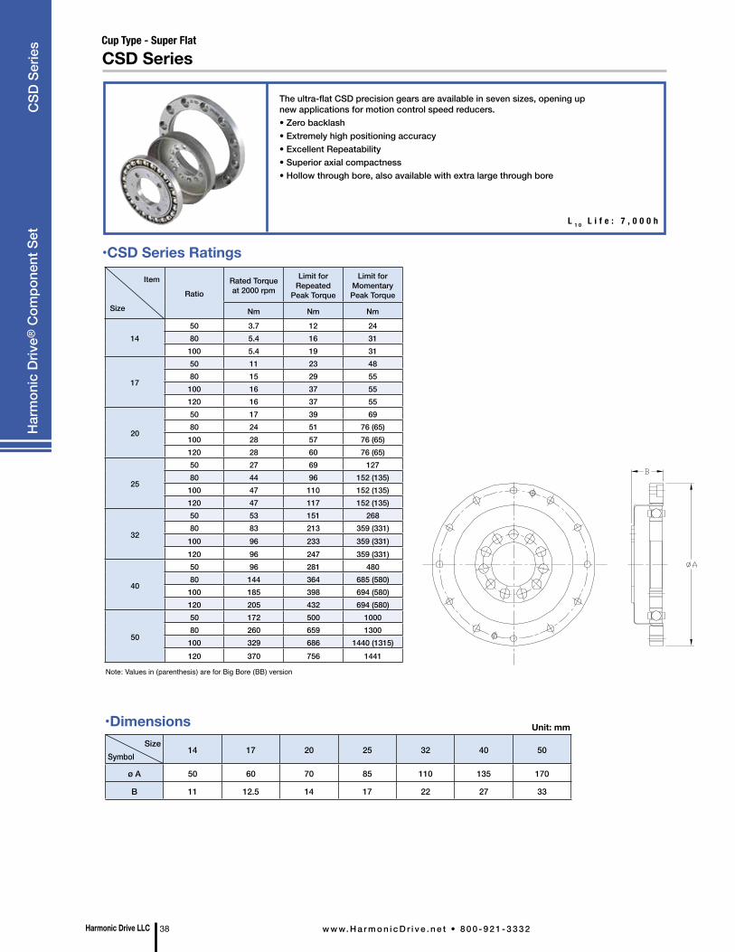
The ultra-flat CSD precision gears are available in seven sizes, opening up
new applications for motion control speed reducers. • Zero backlash • Extremely high positioning accuracy • Excellent Repeatability • Superior axial compactness • Hollow through bore, also available with extra large through bore
•CSD Series Ratings
CSD SeriesCup Type - Super Flat
L 1 0 L i f e : 7 , 0 0 0 h
SizeSymbol
14 17 20 25 32 40 50
ø A 50 60 70 85 110 135 170
B 11 12.5 14 17 22 27 33
Unit: mm
Item
Size
RatioRated Torque at 2000 rpm
Limit for Repeated
Peak Torque
Limit for Momentary Peak Torque
Nm Nm Nm
1450 3.7 12 2480 5.4 16 31100 5.4 19 31
17
50 11 23 4880 15 29 55100 16 37 55120 16 37 55
20
50 17 39 6980 24 51 76 (65)100 28 57 76 (65)120 28 60 76 (65)
25
50 27 69 12780 44 96 152 (135)100 47 110 152 (135)120 47 117 152 (135)
32
50 53 151 26880 83 213 359 (331)100 96 233 359 (331)120 96 247 359 (331)
40
50 96 281 48080 144 364 685 (580)100 185 398 694 (580)120 205 432 694 (580)
50
50 172 500 100080 260 659 1300100 329 686 1440 (1315)120 370 756 1441
•Dimensions
Note: Values in (parenthesis) are for Big Bore (BB) version
Harmonic Drive LLC 38 w w w. H a r m o n i c D r i v e . n e t • 8 0 0 - 9 2 1 - 3 3 3 2
Har
mon
ic D
rive®
Com
pone
nt S
etC
SD S
erie
s
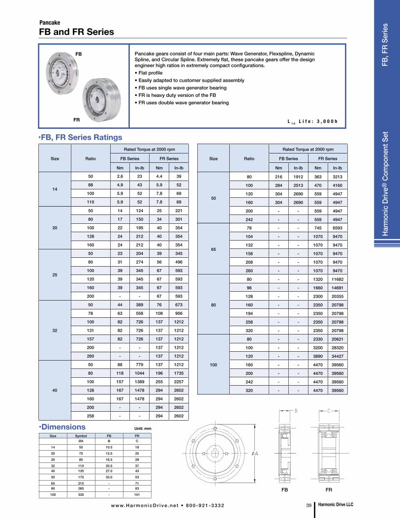
•FB, FR Series Ratings
FB
FR
Pancake
Pancake gears consist of four main parts: Wave Generator, Flexspline, Dynamic Spline, and Circular Spline. Extremely flat, these pancake gears offer the design engineer high ratios in extremely compact configurations.• Flat profile• Easily adapted to customer supplied assembly• FB uses single wave generator bearing• FR is heavy duty version of the FB• FR uses double wave generator bearing
L 1 0 L i f e : 3 , 0 0 0 h
Size Symbol FB FRØA B C
14 50 10.5 18
20 70 12.5 25
25 85 16.5 29
32 110 20.5 3740 135 27.0 43
50 170 33.0 53
65 215 - 7180 265 - 83
100 330 - 101
Unit: mm
FB FR
Size Ratio
Rated Torque at 2000 rpm
FB Series FR Series
Nm In-lb Nm In-lb
14
50 2.6 23 4.4 39
88 4.9 43 5.9 52
100 5.9 52 7.8 69
110 5.9 52 7.8 69
20
50 14 124 25 221
80 17 150 34 301
100 22 195 40 354
128 24 212 40 354
160 24 212 40 354
25
50 23 204 39 345
80 31 274 56 496
100 39 345 67 593
120 39 345 67 593
160 39 345 67 593
200 - - 67 593
32
50 44 389 76 673
78 63 558 108 956
100 82 726 137 1212
131 82 726 137 1212
157 82 726 137 1212
200 - - 137 1212
260 - - 137 1212
40
50 88 779 137 1212
80 118 1044 196 1735
100 157 1389 255 2257
128 167 1478 294 2602
160 167 1478 294 2602
200 - - 294 2602
258 - - 294 2602
Size Ratio
Rated Torque at 2000 rpm
FB Series FR Series
Nm In-lb Nm In-lb
50
80 216 1912 363 3213
100 284 2513 470 4160
120 304 2690 559 4947
160 304 2690 559 4947
200 - - 559 4947
242 - - 559 4947
65
78 - - 745 6593
104 - - 1070 9470
132 - - 1070 9470
158 - - 1070 9470
208 - - 1070 9470
260 - - 1070 9470
80
80 - - 1320 11682
96 - - 1660 14691
128 - - 2300 20355
160 - - 2350 20798
194 - - 2350 20798
258 - - 2350 20798
320 - - 2350 20798
100
80 - - 2330 20621
100 - - 3200 28320
120 - - 3890 34427
160 - - 4470 39560
200 - - 4470 39560
242 - - 4470 39560
320 - - 4470 39560
•Dimensions
Harmonic Drive LLCw w w. H a r m o n i c D r i v e . n e t • 8 0 0 - 9 2 1 - 3 3 3 2 39
Harm
onic
Driv
e® C
ompo
nent
Set
FB and FR Series
FB, F
R Se
ries

•Dimensions
Harmonic Drive LLC 40 w w w. H a r m o n i c D r i v e . n e t • 8 0 0 - 9 2 1 - 3 3 3 2
Har
mon
ic D
rive®
Com
pone
nt S
et
SHF
Serie
s
•SHF Series Ratings
SHF is a silk hat, component set gear available with a large hollow through bore. It provides exceptional positioning accuracy in a compact design.• Zero backlash• Hollow bore units available• Compact and simple design• High torque capacity• High positioning accuracy• High torsional stiffness• Housed version of this component set is available (see p. 50)
SizeSymbol
14 17 20 25 32 40 45 50 58
øA 50 60 70 85 110 135 155 170 195
B 28.5 32.5 33.5 37 44 53 58.5 64 75.5
Unit: mm
Item
Size
RatioRated Torque at 2000rpm
Limit for Repeated Peak
Torque
Limit for Momentary Peak
Torque
Nm In-lb Nm In-lb Nm In-lb
14
30 4.0 35 9.0 80 17 150
50 5.4 48 18 159 35 310
80 7.8 69 23 204 47 416
100 7.8 69 28 248 54 478
17
30 8.8 78 16 142 30 266
50 16 142 34 301 70 620
80 22 195 43 381 87 770
100 24 212 54 478 110 974
120 24 212 54 478 86 761
20
30 15 133 27 239 50 443
50 25 221 56 496 98 867
80 34 301 74 655 127 1124
100 40 354 82 726 147 1301
120 40 354 87 770 147 1301
160 40 354 92 814 147 1301
25
30 27 239 50 443 95 841
50 39 345 98 867 86 1646
80 63 558 137 1212 255 2257
100 67 593 157 1389 284 2513
120 67 593 167 1478 304 2690
160 67 593 176 1558 314 2779
32
30 54 478 100 885 200 1770
50 76 673 216 1912 382 3381
80 118 1044 230 2036 568 5027
100 137 1212 333 2947 647 5726
120 137 1212 353 3124 686 6071
160 137 1212 372 3292 686 6071
Item
Size
RatioRated Torque at 2000rpm
Limit for Repeated Peak
Torque
Limit for Momentary Peak Torque
Nm In-lb Nm In-lb Nm In-lb
40
50 137 1212 402 3558 686 6071
80 206 1823 519 4593 980 8673
100 265 2345 568 5027 1080 9558
120 294 2602 617 5460 1180 10443
160 294 2602 647 5726 1180 10443
45
50 176 1558 500 4425 950 8408
80 313 2770 706 6248 1270 11240
100 353 3124 755 6682 1570 13895
120 402 3558 823 7284 1760 15576
160 402 3558 882 7806 1910 16904
50
50 245 2168 715 6328 1430 12656
80 372 3292 941 8328 1860 16461
100 470 4160 980 8673 2060 18231
120 529 4682 1080 9558 2060 18231
160 529 4682 1180 10443 2450 21683
58
50 353 3124 020 9027 1960 17346
80 549 4859 1480 13098 2450 21683
100 696 6160 1590 14072 3180 28143
120 745 6593 1720 15222 3330 29471
160 745 6593 1840 16284 3430 30356
L 1 0 L i f e : 7 , 0 0 0 h
Silk HatSHF Series
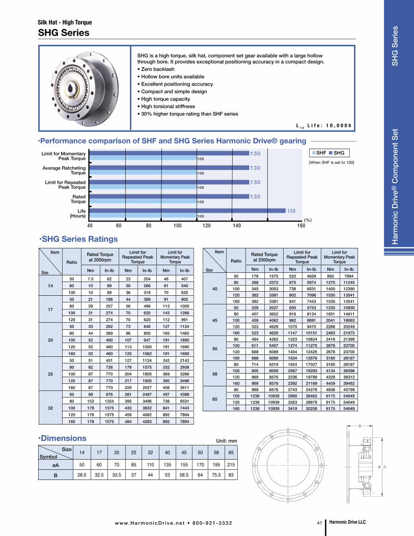
Silk Hat - High Torque
SHG Series
SHG is a high torque, silk hat, component set gear available with a large hollow through bore. It provides exceptional positioning accuracy in a compact design.• Zero backlash• Hollow bore units available• Excellent positioning accuracy• Compact and simple design• High torque capacity• High torsional stiffness• 30% higher torque rating than SHF series
L 1 0 L i f e : 1 0 , 0 0 0 h
SizeSymbol
14 17 20 25 32 40 45 50 58 65
øA 50 60 70 85 110 135 155 170 195 215
B 28.5 32.5 33.5 37 44 53 58.5 64 75.5 83
Unit: mm
•SHG Series Ratings
100
100
100
100
100
130
130
130
130
150
40 60 80 100 120 140 160(%)
SHF SHG
•Performance comparison of SHF and SHG Series Harmonic Drive® gearing
Item
Size
RatioRated Torque at 2000rpm
Limit for Repeated Peak
Torque
Limit for Momentary Peak
TorqueNm In-lb Nm In-lb Nm In-lb
40
50 178 1575 523 4629 892 789480 268 2372 675 5974 1270 11240
100 345 3053 738 6531 1400 12390120 382 3381 802 7098 1530 13541160 382 3381 841 7443 1530 13541
45
50 229 2027 650 5753 1235 1093080 407 3602 918 8124 1651 14611
100 459 4062 982 8691 2041 18063120 523 4629 1070 9470 2288 20249160 523 4629 1147 10151 2483 21975
50
80 484 4283 1223 10824 2418 21399100 611 5407 1274 11275 2678 23700120 688 6089 1404 12425 2678 23700160 688 6089 1534 13576 3185 28187
58
80 714 6319 1924 17027 3185 28187100 905 8009 2067 18293 4134 36586120 969 8576 2236 19789 4329 38312160 969 8576 2392 21169 4459 39462
65
80 969 8576 2743 24276 4836 42799100 1236 10939 2990 26462 6175 54649120 1236 10939 3263 28878 6175 54649160 1236 10939 3419 30258 6175 54649
Item
Size
RatioRated Torque at 2000rpm
Limit for Repeated Peak
Torque
Limit for Momentary Peak
Torque
Nm In-lb Nm In-lb Nm In-lb
1450 7.0 62 23 204 46 40780 10 89 30 266 61 540100 10 89 36 319 70 620
17
50 21 186 44 389 91 80580 29 257 56 496 113 1000100 31 274 70 620 143 1266120 31 274 70 620 112 991
20
50 33 292 73 646 127 112480 44 389 96 850 165 1460100 52 460 107 947 191 1690120 52 460 113 1000 191 1690160 52 460 120 1062 191 1690
25
50 51 451 127 1124 242 214280 82 726 178 1575 332 2938100 87 770 204 1805 369 3266120 87 770 217 1920 395 3496160 87 770 229 2027 408 3611
32
50 99 876 281 2487 497 439880 153 1354 395 3496 738 6531100 178 1575 433 3832 841 7443120 178 1575 459 4062 892 7894160 178 1575 484 4283 892 7894
Limit for Momentary Peak Torque
Average RatchetingTorque
Limit for Repeated Peak Torque
Rated Torque
Life (Hours)
[When SHF is set to 100]
•Dimensions
Harmonic Drive LLCw w w. H a r m o n i c D r i v e . n e t • 8 0 0 - 9 2 1 - 3 3 3 2 41
Har
mon
ic D
rive®
Com
pone
nt S
et
SHG
Ser
ies
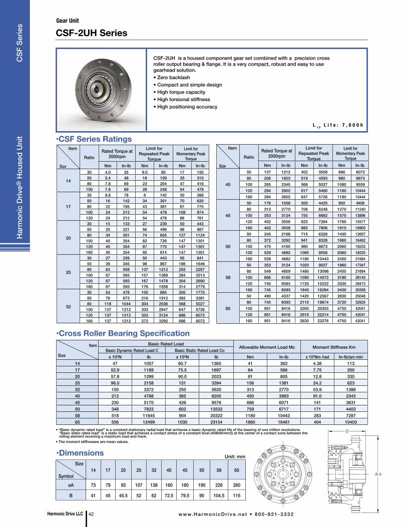
•Dimensions
Harmonic Drive LLC 42 w w w. H a r m o n i c D r i v e . n e t • 8 0 0 - 9 2 1 - 3 3 3 2
CSF-2UH is a housed component gear set combined with a precision cross roller output bearing & flange. It is a very compact, robust and easy to use gearhead solution.• Zero backlash• Compact and simple design• High torque capacity• High torsional stiffness• High positioning accuracy
CSF-2UH Series
Size
Symbol14 17 20 25 32 40 45 50 58 65
øA 73 79 93 107 138 160 180 190 226 260
B 41 45 45.5 52 62 72.5 79.5 90 104.5 115
Unit: mm
Item
Size
Basic Rated LoadAllowable Moment Load Mc Moment Stiffness Km
Basic Dynamic Rated Load C Basic Static Rated Load Cox 102N lb x 102N lb Nm In-lb x 104Nm /rad In-lb/arc-min
14 47 1057 60.7 1365 41 363 4.38 11317 52.9 1189 75.5 1697 64 566 7.75 20020 57.8 1299 90.0 2023 91 805 12.8 33025 96.0 2158 151 3394 156 1381 24.2 62332 150 3372 250 5620 313 2770 53.9 138840 213 4788 365 8205 450 3983 91.0 234345 230 5170 426 9576 686 6071 141 363150 348 7823 602 13533 759 6717 171 440358 518 11645 904 20322 1180 10443 283 728765 556 12499 1030 23154 1860 16461 404 10403
•Cross Roller Bearing Specification
•CSF Series Ratings
• “Basic dynamic rated load” is a constant stationary radial load that achieves a basic dynamic rated life of the bearing of one million revolutions. “Basic static rated load” is a static load that achieves a contact stress of a constant level (408kN/mm2) at the center of a contact zone between the rolling element receiving a maximum load and track.
• The moment stiffnesses are mean values.
Item
Size
RatioRated Torque at
2000rpmLimit for
Repeated Peak Torque
Limit for Momentary Peak
TorqueNm In-lb Nm In-lb Nm In-lb
14
30 4.0 35 9.0 80 17 15050 5.4 48 18 159 35 31080 7.8 69 23 204 47 416100 7.8 69 28 248 54 478
17
30 8.8 78 6 142 30 26650 16 142 34 301 70 62080 22 195 43 381 87 770100 24 212 54 478 108 974120 24 212 54 478 86 761
20
30 15 133 27 239 50 44350 25 221 56 496 98 86780 34 301 74 655 127 1124100 40 354 82 726 147 1301120 40 354 87 770 147 1301160 40 354 92 814 147 1301
25
30 27 239 50 443 95 84150 39 345 98 867 186 164680 63 558 137 1212 255 2257100 67 593 157 1389 284 2513120 67 593 167 1478 304 2690160 67 593 176 1558 314 2779
32
30 54 478 100 885 200 177050 76 673 216 1912 382 338180 118 1044 304 2036 568 5027100 137 1212 333 2947 647 5726120 137 1212 353 3124 686 6072160 137 1212 372 3292 686 6072
Item
Size
RatioRated Torque at
2000rpmLimit for
Repeated Peak Torque
Limit for Momentary Peak
TorqueNm In-lb Nm In-lb Nm In-lb
40
50 137 1212 402 3558 686 6072 80 206 1823 519 4593 980 8674
100 265 2345 568 5027 1080 9559 120 294 2602 617 5460 1180 10444 160 294 2602 647 5726 1180 10444
45
50 176 1558 500 4425 950 8408 80 313 2770 706 6248 1270 11240 100 353 3124 755 6682 1570 13896 120 402 3558 823 7284 1760 15577 160 402 3558 882 7806 1910 16905
50
50 245 2168 715 6328 1430 12657 80 372 3292 941 8328 1860 16462 100 470 4160 980 8673 2060 18233 120 529 4682 1080 9558 2060 18233 160 529 4682 1180 10443 2450 21684
58
50 353 3124 1020 9027 1960 17347 80 549 4859 1480 13098 2450 21684 100 686 6160 1590 14072 3180 28145 120 745 6593 1720 15222 3330 29473 160 745 6593 1840 16284 3430 30358
65
50 490 4337 1420 12567 2830 25048 80 745 6593 2110 18674 3720 32925 100 951 8416 2300 20355 4750 42041 120 951 8416 2510 22214 4750 42041 160 951 8416 2630 23276 4750 42041
L 1 0 L i f e : 7 , 0 0 0 h
Har
mon
ic D
rive®
Hou
sed
Uni
t C
SF S
erie
s Gear Unit
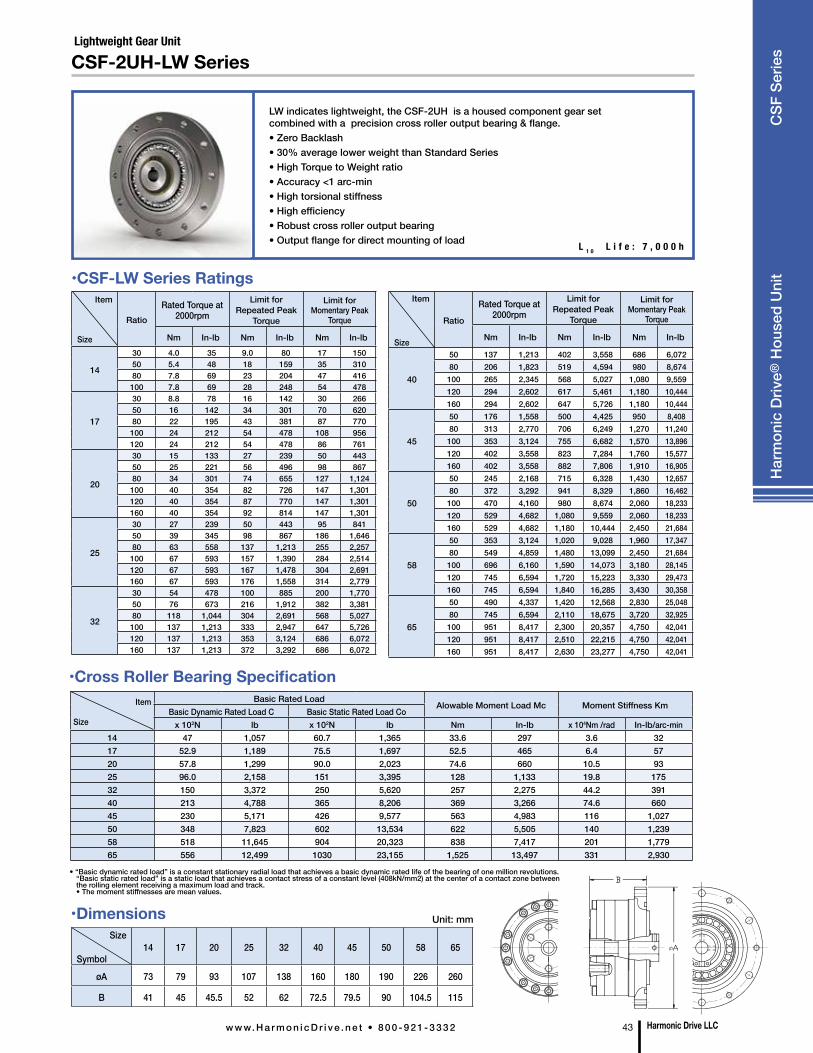
Harmonic Drive LLCw w w. H a r m o n i c D r i v e . n e t • 8 0 0 - 9 2 1 - 3 3 3 2 43
Har
mon
ic D
rive®
Hou
sed
Uni
t C
SF S
erie
s
•Cross Roller Bearing SpecificationItem
Size
Basic Rated LoadAlowable Moment Load Mc Moment Stiffness Km
Basic Dynamic Rated Load C Basic Static Rated Load Cox 102N lb x 102N lb Nm In-lb x 104Nm /rad In-lb/arc-min
14 47 1,057 60.7 1,365 33.6 297 3.6 32 17 52.9 1,189 75.5 1,697 52.5 465 6.4 57 20 57.8 1,299 90.0 2,023 74.6 660 10.5 93 25 96.0 2,158 151 3,395 128 1,133 19.8 175 32 150 3,372 250 5,620 257 2,275 44.2 391 40 213 4,788 365 8,206 369 3,266 74.6 660 45 230 5,171 426 9,577 563 4,983 116 1,027 50 348 7,823 602 13,534 622 5,505 140 1,239 58 518 11,645 904 20,323 838 7,417 201 1,779 65 556 12,499 1030 23,155 1,525 13,497 331 2,930
Item
Size
RatioRated Torque at
2000rpmLimit for
Repeated Peak Torque
Limit for Momentary Peak
Torque
Nm In-lb Nm In-lb Nm In-lb
14
30 4.0 35 9.0 80 17 150 50 5.4 48 18 159 35 310 80 7.8 69 23 204 47 416 100 7.8 69 28 248 54 478
17
30 8.8 78 16 142 30 266 50 16 142 34 301 70 620 80 22 195 43 381 87 770 100 24 212 54 478 108 956 120 24 212 54 478 86 761
20
30 15 133 27 239 50 443 50 25 221 56 496 98 867 80 34 301 74 655 127 1,124
100 40 354 82 726 147 1,301 120 40 354 87 770 147 1,301 160 40 354 92 814 147 1,301
25
30 27 239 50 443 95 841 50 39 345 98 867 186 1,646 80 63 558 137 1,213 255 2,257 100 67 593 157 1,390 284 2,514 120 67 593 167 1,478 304 2,691 160 67 593 176 1,558 314 2,779
32
30 54 478 100 885 200 1,770 50 76 673 216 1,912 382 3,381 80 118 1,044 304 2,691 568 5,027 100 137 1,213 333 2,947 647 5,726 120 137 1,213 353 3,124 686 6,072 160 137 1,213 372 3,292 686 6,072
Item
Size
Ratio
Rated Torque at 2000rpm
Limit for Repeated Peak
Torque
Limit for Momentary Peak
Torque
Nm In-lb Nm In-lb Nm In-lb
40
50 137 1,213 402 3,558 686 6,072 80 206 1,823 519 4,594 980 8,674
100 265 2,345 568 5,027 1,080 9,559 120 294 2,602 617 5,461 1,180 10,444 160 294 2,602 647 5,726 1,180 10,444
45
50 176 1,558 500 4,425 950 8,408 80 313 2,770 706 6,249 1,270 11,240 100 353 3,124 755 6,682 1,570 13,896 120 402 3,558 823 7,284 1,760 15,577 160 402 3,558 882 7,806 1,910 16,905
50
50 245 2,168 715 6,328 1,430 12,657 80 372 3,292 941 8,329 1,860 16,462 100 470 4,160 980 8,674 2,060 18,233 120 529 4,682 1,080 9,559 2,060 18,233 160 529 4,682 1,180 10,444 2,450 21,684
58
50 353 3,124 1,020 9,028 1,960 17,347 80 549 4,859 1,480 13,099 2,450 21,684 100 696 6,160 1,590 14,073 3,180 28,145 120 745 6,594 1,720 15,223 3,330 29,473 160 745 6,594 1,840 16,285 3,430 30,358
65
50 490 4,337 1,420 12,568 2,830 25,048 80 745 6,594 2,110 18,675 3,720 32,925 100 951 8,417 2,300 20,357 4,750 42,041 120 951 8,417 2,510 22,215 4,750 42,041 160 951 8,417 2,630 23,277 4,750 42,041
LW indicates lightweight, the CSF-2UH is a housed component gear set combined with a precision cross roller output bearing & flange.• Zero Backlash • 30% average lower weight than Standard Series • High Torque to Weight ratio• Accuracy <1 arc-min • High torsional stiffness • High efficiency • Robust cross roller output bearing • Output flange for direct mounting of load
CSF-2UH-LW Series
•CSF-LW Series Ratings
Lightweight Gear Unit
L 1 0 L i f e : 7 , 0 0 0 h
• “Basic dynamic rated load” is a constant stationary radial load that achieves a basic dynamic rated life of the bearing of one million revolutions. “Basic static rated load” is a static load that achieves a contact stress of a constant level (408kN/mm2) at the center of a contact zone between the rolling element receiving a maximum load and track. • The moment stiffnesses are mean values.
Size
Symbol14 17 20 25 32 40 45 50 58 65
øA 73 79 93 107 138 160 180 190 226 260
B 41 45 45.5 52 62 72.5 79.5 90 104.5 115
Unit: mm•Dimensions
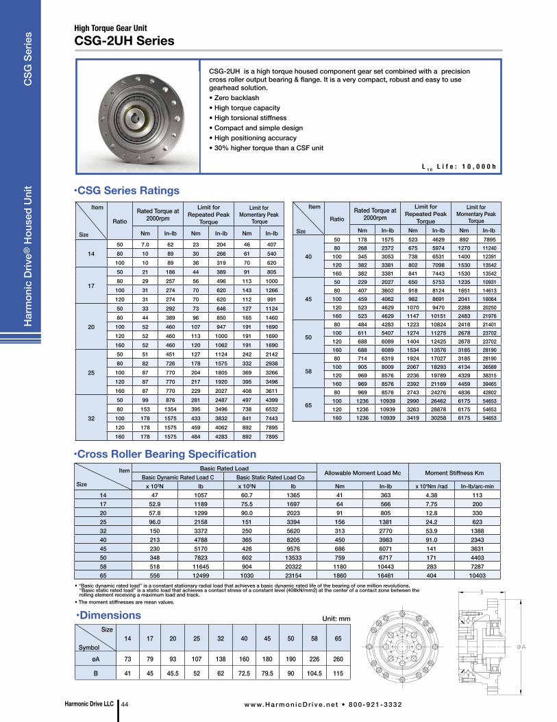
L 1 0 L i f e : 1 0 , 0 0 0 h
Size
Symbol14 17 20 25 32 40 45 50 58 65
øA 73 79 93 107 138 160 180 190 226 260
B 41 45 45.5 52 62 72.5 79.5 90 104.5 115
Unit: mm
• “Basic dynamic rated load” is a constant stationary radial load that achieves a basic dynamic rated life of the bearing of one million revolutions. “Basic static rated load” is a static load that achieves a contact stress of a constant level (408kN/mm2) at the center of a contact zone between the rolling element receiving a maximum load and track.
• The moment stiffnesses are mean values.
•Cross Roller Bearing SpecificationItem
Size
Basic Rated LoadAllowable Moment Load Mc Moment Stiffness Km
Basic Dynamic Rated Load C Basic Static Rated Load Cox 102N lb x 102N lb Nm In-lb x 104Nm /rad In-lb/arc-min
14 47 1057 60.7 1365 41 363 4.38 11317 52.9 1189 75.5 1697 64 566 7.75 20020 57.8 1299 90.0 2023 91 805 12.8 33025 96.0 2158 151 3394 156 1381 24.2 62332 150 3372 250 5620 313 2770 53.9 138840 213 4788 365 8205 450 3983 91.0 234345 230 5170 426 9576 686 6071 141 363150 348 7823 602 13533 759 6717 171 440358 518 11645 904 20322 1180 10443 283 728765 556 12499 1030 23154 1860 16461 404 10403
•CSG Series RatingsItem
Size
RatioRated Torque at
2000rpmLimit for
Repeated Peak Torque
Limit for Momentary Peak
Torque
Nm In-lb Nm In-lb Nm In-lb
1450 7.0 62 23 204 46 40780 10 89 30 266 61 540100 10 89 36 319 70 620
17
50 21 186 44 389 91 80580 29 257 56 496 113 1000100 31 274 70 620 143 1266120 31 274 70 620 112 991
20
50 33 292 73 646 127 112480 44 389 96 850 165 1460100 52 460 107 947 191 1690120 52 460 113 1000 191 1690160 52 460 120 1062 191 1690
25
50 51 451 127 1124 242 214280 82 726 178 1575 332 2938100 87 770 204 1805 369 3266120 87 770 217 1920 395 3496160 87 770 229 2027 408 3611
32
50 99 876 281 2487 497 439980 153 1354 395 3496 738 6532100 178 1575 433 3832 841 7443120 178 1575 459 4062 892 7895160 178 1575 484 4283 892 7895
Item
Size
RatioRated Torque at
2000rpmLimit for
Repeated Peak Torque
Limit for Momentary Peak
TorqueNm In-lb Nm In-lb Nm In-lb
40
50 178 1575 523 4629 892 7895 80 268 2372 675 5974 1270 11240 100 345 3053 738 6531 1400 12391 120 382 3381 802 7098 1530 13542 160 382 3381 841 7443 1530 13542
45
50 229 2027 650 5753 1235 10931 80 407 3602 918 8124 1651 14613 100 459 4062 982 8691 2041 18064 120 523 4629 1070 9470 2288 20250 160 523 4629 1147 10151 2483 21976
50
80 484 4283 1223 10824 2418 21401 100 611 5407 1274 11275 2678 23702 120 688 6089 1404 12425 2678 23702 160 688 6089 1534 13576 3185 28190
58
80 714 6319 1924 17027 3185 28190 100 905 8009 2067 18293 4134 36589 120 969 8576 2236 19789 4329 38315 160 969 8576 2392 21169 4459 39465
65
80 969 8576 2743 24276 4836 42802 100 1236 10939 2990 26462 6175 54653 120 1236 10939 3263 28878 6175 54653 160 1236 10939 3419 30258 6175 54653
CSG-2UH is a high torque housed component gear set combined with a precision cross roller output bearing & flange. It is a very compact, robust and easy to use gearhead solution.• Zero backlash• High torque capacity• High torsional stiffness• Compact and simple design• High positioning accuracy• 30% higher torque than a CSF unit
Harmonic Drive LLC 44 w w w. H a r m o n i c D r i v e . n e t • 8 0 0 - 9 2 1 - 3 3 3 2
Har
mon
ic D
rive®
Hou
sed
Uni
t C
SG S
erie
s High Torque Gear UnitCSG-2UH Series
•Dimensions
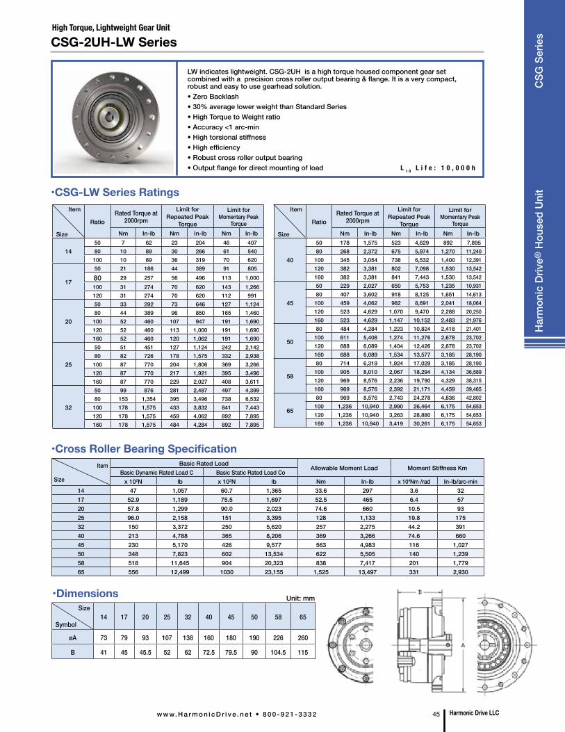
LW indicates lightweight. CSG-2UH is a high torque housed component gear set combined with a precision cross roller output bearing & flange. It is a very compact, robust and easy to use gearhead solution.• Zero Backlash • 30% average lower weight than Standard Series • High Torque to Weight ratio• Accuracy <1 arc-min • High torsional stiffness • High efficiency • Robust cross roller output bearing • Output flange for direct mounting of load
CSG-2UH-LW Series
Item
Size
Basic Rated LoadAllowable Moment Load Moment Stiffness Km
Basic Dynamic Rated Load C Basic Static Rated Load Cox 102N lb x 102N lb Nm In-lb x 104Nm /rad In-lb/arc-min
14 47 1,057 60.7 1,365 33.6 297 3.6 32 17 52.9 1,189 75.5 1,697 52.5 465 6.4 57 20 57.8 1,299 90.0 2,023 74.6 660 10.5 93 25 96.0 2,158 151 3,395 128 1,133 19.8 175 32 150 3,372 250 5,620 257 2,275 44.2 391 40 213 4,788 365 8,206 369 3,266 74.6 660 45 230 5,170 426 9,577 563 4,983 116 1,027 50 348 7,823 602 13,534 622 5,505 140 1,239 58 518 11,645 904 20,323 838 7,417 201 1,779 65 556 12,499 1030 23,155 1,525 13,497 331 2,930
•Cross Roller Bearing Specification
•CSG-LW Series RatingsItem
Size
RatioRated Torque at
2000rpmLimit for
Repeated Peak Torque
Limit for Momentary Peak
TorqueNm In-lb Nm In-lb Nm In-lb
1450 7 62 23 204 46 407 80 10 89 30 266 61 540 100 10 89 36 319 70 620
17
50 21 186 44 389 91 805 80 29 257 56 496 113 1,000 100 31 274 70 620 143 1,266 120 31 274 70 620 112 991
20
50 33 292 73 646 127 1,124 80 44 389 96 850 165 1,460 100 52 460 107 947 191 1,690 120 52 460 113 1,000 191 1,690 160 52 460 120 1,062 191 1,690
25
50 51 451 127 1,124 242 2,142 80 82 726 178 1,575 332 2,938 100 87 770 204 1,806 369 3,266 120 87 770 217 1,921 395 3,496 160 87 770 229 2,027 408 3,611
32
50 99 876 281 2,487 497 4,399 80 153 1,354 395 3,496 738 6,532 100 178 1,575 433 3,832 841 7,443 120 178 1,575 459 4,062 892 7,895 160 178 1,575 484 4,284 892 7,895
Item
Size
RatioRated Torque at
2000rpmLimit for
Repeated Peak Torque
Limit for Momentary Peak
TorqueNm In-lb Nm In-lb Nm In-lb
40
50 178 1,575 523 4,629 892 7,895 80 268 2,372 675 5,974 1,270 11,240 100 345 3,054 738 6,532 1,400 12,391 120 382 3,381 802 7,098 1,530 13,542 160 382 3,381 841 7,443 1,530 13,542
45
50 229 2,027 650 5,753 1,235 10,931 80 407 3,602 918 8,125 1,651 14,613 100 459 4,062 982 8,691 2,041 18,064 120 523 4,629 1,070 9,470 2,288 20,250 160 523 4,629 1,147 10,152 2,483 21,976
50
80 484 4,284 1,223 10,824 2,418 21,401 100 611 5,408 1,274 11,276 2,678 23,702 120 688 6,089 1,404 12,426 2,678 23,702 160 688 6,089 1,534 13,577 3,185 28,190
58
80 714 6,319 1,924 17,029 3,185 28,190 100 905 8,010 2,067 18,294 4,134 36,589 120 969 8,576 2,236 19,790 4,329 38,315 160 969 8,576 2,392 21,171 4,459 39,465
65
80 969 8,576 2,743 24,278 4,836 42,802 100 1,236 10,940 2,990 26,464 6,175 54,653 120 1,236 10,940 3,263 28,880 6,175 54,653 160 1,236 10,940 3,419 30,261 6,175 54,653
L 1 0 L i f e : 1 0 , 0 0 0 h
Harmonic Drive LLCw w w. H a r m o n i c D r i v e . n e t • 8 0 0 - 9 2 1 - 3 3 3 2 45
High Torque, Lightweight Gear Unit
Har
mon
ic D
rive®
Hou
sed
Uni
t C
SG S
erie
s
Size
Symbol14 17 20 25 32 40 45 50 58 65
øA 73 79 93 107 138 160 180 190 226 260
B 41 45 45.5 52 62 72.5 79.5 90 104.5 115
Unit: mm•Dimensions
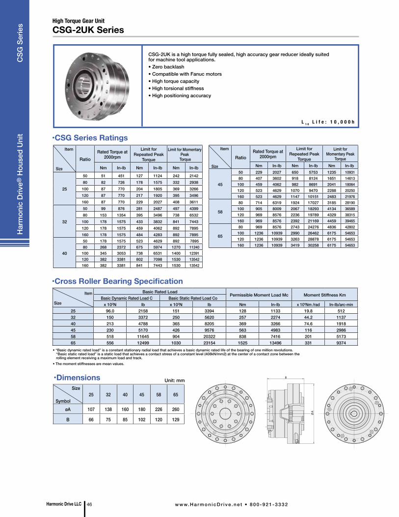
CSG-2UK is a high torque fully sealed, high accuracy gear reducer ideally suited for machine tool applications. • Zero backlash• Compatible with Fanuc motors • High torque capacity• High torsional stiffness• High positioning accuracy
L 1 0 L i f e : 1 0 , 0 0 0 h
Size
Symbol25 32 40 45 58 65
øA 107 138 160 180 226 260
B 66 75 85 102 120 129
Unit: mm
• “Basic dynamic rated load” is a constant stationary radial load that achieves a basic dynamic rated life of the bearing of one million revolutions. “Basic static rated load” is a static load that achieves a contact stress of a constant level (408kN/mm2) at the center of a contact zone between the rolling element receiving a maximum load and track.
• The moment stiffnesses are mean values.
•Cross Roller Bearing SpecificationItem
Size
Basic Rated LoadPermissible Moment Load Mc Moment Stiffness Km
Basic Dynamic Rated Load C Basic Static Rated Load Cox 102N lb x 102N lb Nm In-lb x 104Nm /rad In-lb/arc-min
25 96.0 2158 151 3394 128 1133 19.8 51232 150 3372 250 5620 257 2274 44.2 113740 213 4788 365 8205 369 3266 74.6 191845 230 5170 426 9576 563 4983 116 298658 518 11645 904 20322 838 7416 201 517365 556 12499 1030 23154 1525 13496 331 9374
•CSG Series RatingsItem
Size
RatioRated Torque at
2000rpmLimit for
Repeated Peak Torque
Limit for Momentary Peak
Torque
Nm In-lb Nm In-lb Nm In-lb
25
50 51 451 127 1124 242 214280 82 726 178 1575 332 2938100 87 770 204 1805 369 3266120 87 770 217 1920 395 3496160 87 770 229 2027 408 3611
32
50 99 876 281 2487 497 439980 153 1354 395 3496 738 6532100 178 1575 433 3832 841 7443120 178 1575 459 4062 892 7895160 178 1575 484 4283 892 7895
40
50 178 1575 523 4629 892 7895 80 268 2372 675 5974 1270 11240 100 345 3053 738 6531 1400 12391 120 382 3381 802 7098 1530 13542 160 382 3381 841 7443 1530 13542
Item
Size
RatioRated Torque at
2000rpmLimit for
Repeated Peak Torque
Limit for Momentary Peak
TorqueNm In-lb Nm In-lb Nm In-lb
45
50 229 2027 650 5753 1235 10931 80 407 3602 918 8124 1651 14613 100 459 4062 982 8691 2041 18064 120 523 4629 1070 9470 2288 20250 160 523 4629 1147 10151 2483 21976
58
80 714 6319 1924 17027 3185 28190 100 905 8009 2067 18293 4134 36589 120 969 8576 2236 19789 4329 38315 160 969 8576 2392 21169 4459 39465
65
80 969 8576 2743 24276 4836 42802 100 1236 10939 2990 26462 6175 54653 120 1236 10939 3263 28878 6175 54653 160 1236 10939 3419 30258 6175 54653
B
ØA
•Dimensions
Harmonic Drive LLC 46 w w w. H a r m o n i c D r i v e . n e t • 8 0 0 - 9 2 1 - 3 3 3 2
Har
mon
ic D
rive®
Hou
sed
Uni
t C
SG S
erie
s High Torque Gear UnitCSG-2UK Series
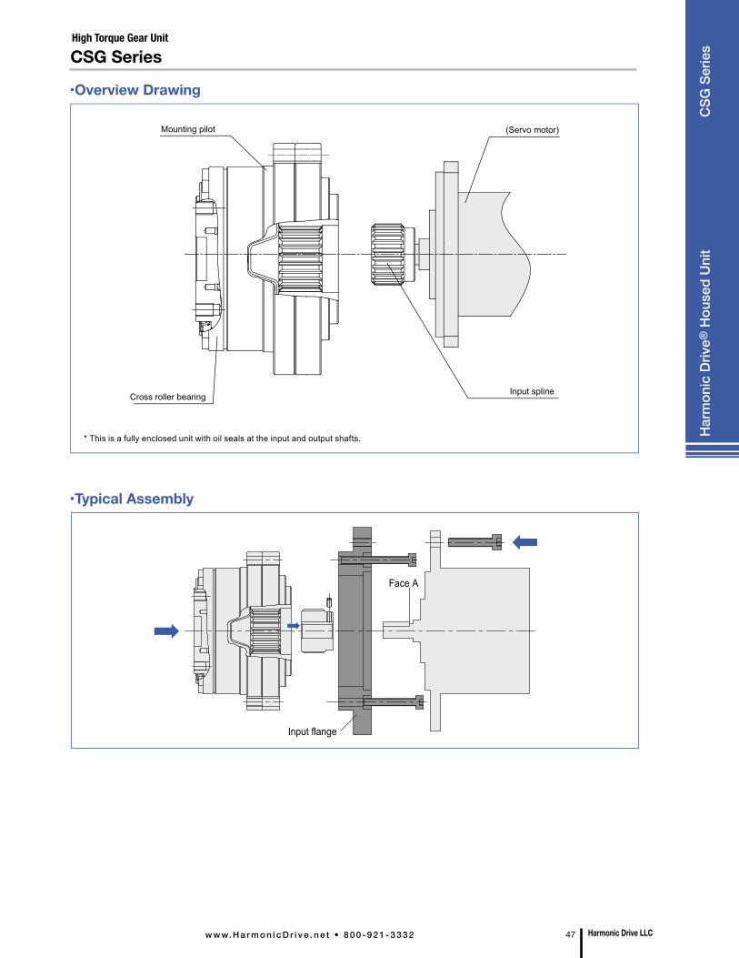
•Typical Assembly
•Overview Drawing
CSG Series
* This is a fully enclosed unit with oil seals at the input and output shafts.
Mounting pilot
Cross roller bearing Input spline
(Servo motor)
Face A
Input flange
Harmonic Drive LLCw w w. H a r m o n i c D r i v e . n e t • 8 0 0 - 9 2 1 - 3 3 3 2 47
High Torque Gear Unit
Har
mon
ic D
rive®
Hou
sed
Uni
t C
SG S
erie
s
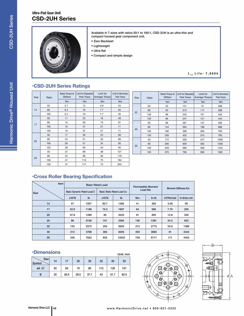
L 1 0 L i f e : 7 , 0 0 0 h
•CSD-2UH Series Ratings
Size Symbol
14 17 20 25 32 40 50
øA h7 55 62 70 85 112 126 157
B 25 26.5 29.5 37.1 43 51.7 62.5
Unit: mm
•Cross Roller Bearing SpecificationItem
Size
Basic Rated Load Permissible Moment Load Mc Moment Stiffness Km
Basic Dynamic Rated Load C Basic Static Rated Load Co
x102N lb x102N lb Nm In-lb x104Nm/rad In-lb/arc.min
14 47 1057 60.7 1365 41 363 3.48 90
17 52.9 1189 75.5 1697 64 566 7.75 200
20 57.8 1299 90 2023 91 805 12.8 330
25 96 2158 151 3394 156 1381 24.2 623
32 150 3372 250 5620 313 2770 53.9 1388
40 213 4788 365 8205 450 3983 91 2343
50 348 7823 602 13533 759 6717 171 4403
•Dimensions
Size RatioRated Torque at
2000rpmLimit for Repeated
Peak TorqueLimit for
Average TorqueLimit for Momentary
Peak Torque
Nm Nm Nm Nm
1450 3.7 12 4.8 2480 5.4 16 7.7 35100 5.4 19 7.7 35
17
50 11 23 18 4880 15 29 19 61100 16 37 27 71120 16 37 27 71
20
50 17 39 24 6980 24 51 33 89100 28 57 34 95120 28 60 34 95
25
50 27 69 38 12780 44 96 60 179100 47 110 75 184120 47 117 75 204
Size RatioRated Torque at
2000rpmLimit for Repeated
Peak TorqueLimit for
Average TorqueLimit for Momentary
Peak Torque
Nm Nm Nm Nm
32
50 53 151 75 26880 83 213 117 398100 96 233 151 420120 96 247 151 445
40
50 96 281 137 48080 144 364 198 686100 185 398 260 700120 205 432 315 765
50
50 172 500 247 100080 260 659 363 1300100 329 686 466 1440120 370 756 569 1565
Harmonic Drive LLC 48 w w w. H a r m o n i c D r i v e . n e t • 8 0 0 - 9 2 1 - 3 3 3 2
Har
mon
ic D
rive®
Hou
sed
Uni
t
CSD
-2U
H S
erie
s Ultra-Flat Gear UnitCSD-2UH Series
Available in 7 sizes with ratios 50:1 to 160:1, CSD-2UH is an ultra-thin and compact housed gear component unit. • Zero Backlash• Lightweight• Ultra-flat• Compact and simple design

•CSD-2UF Series Ratings
Size Symbol
14 17 20 25 32 40
øA h7 70 80 90 110 142 170
B 22 22.7 26.8 31.5 37 45
Unit: mm
Ultra-Flat, Hollow Shaft Gear Unit
L 1 0 L i f e : 7 , 0 0 0 h
CSD-2UF Series
•Cross Roller Bearing Specification
Available in 6 sizes with ratios 50:1 to 160:1, CSD-2UF is an ultra-thin and compact housed gear component unit with a hollow through bore. • Zero Backlash• Hollow shaft• High load capacity• Lightweight• Ultra-flat• Compact and simple design
Item
Size
Basic Rated Load Permissible Moment Load Mc Moment Stiffness Km
Basic Dynamic Rated Load C Basic Static Rated Load Co
x102N lb x102N lb Nm In-lb x104Nm/rad In-lb/arc.min
14 57.8 1299 90 2023 91 805 12.8 330
17 104 2338 163 3664 124 1097 15.4 397
20 146 3282 220 4946 187 1655 25.2 649
25 218 4901 358 8048 258 2283 39.2 1009
32 382 8587 654 14702 580 5133 100 2575
40 433 9734 816 18344 849 7514 179 4609
•Dimensions
Size RatioRated Torque at
2000rpmLimit for Repeated
Peak TorqueLimit for
Average TorqueLimit for Momentary
Peak Torque
Nm Nm Nm Nm
1450 3.7 12 4.8 2480 5.4 16 7.7 35100 5.4 19 7.7 35
17
50 11 23 18 4880 15 29 19 61100 16 37 27 71120 16 37 27 71
20
50 17 39 24 6980 24 51 33 89100 28 57 34 95120 28 60 34 95
25
50 27 69 38 12780 44 96 60 179100 47 110 75 184120 47 117 75 204
Size RatioRated Torque at
2000rpmLimit for Repeated
Peak TorqueLimit for
Average TorqueLimit for Momentary
Peak Torque
Nm Nm Nm Nm
32
50 53 151 75 26880 83 213 117 398100 96 233 151 420120 96 247 151 445
40
50 96 281 137 48080 144 364 198 686100 185 398 260 700120 205 432 315 765
50
50 172 500 247 100080 260 659 363 1300100 329 686 466 1440120 370 756 569 1565
Harmonic Drive LLCw w w. H a r m o n i c D r i v e . n e t • 8 0 0 - 9 2 1 - 3 3 3 2 49
Har
mon
ic D
rive®
Hou
sed
Uni
t C
SD-2
UF
Serie
s
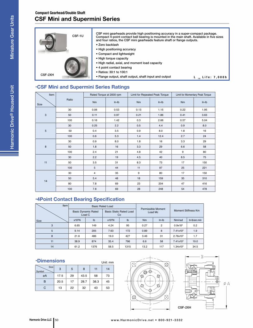
Item
SizeRatio
Rated Torque at 2000 rpm Limit for Repeated Peak Torque Limit for Momentary Peak Torque
Nm In-lb Nm In-lb Nm In-lb
3
30 0.06 0.53 0.13 1.15 0.22 1.95
50 0.11 0.97 0.21 1.86 0.41 3.63
100 0.16 1.42 0.3 2.66 0.57 5.04
5
30 0.25 2.2 0.5 4.4 0.9 8.0
50 0.4 3.5 0.9 8.0 1.8 16
100 0.6 5.3 1.4 12.4 2.7 24
8
30 0.9 8.0 1.8 16 3.3 29
50 1.8 16 3.3 29 6.6 58
100 2.4 21 4.8 42 9 80
11
30 2.2 19 4.5 40 8.5 75
50 3.5 31 8.3 73 17 150
100 5 44 11 97 25 221
14
30 4 35 9 80 17 150
50 5.4 48 18 159 35 310
80 7.8 69 23 204 47 416
100 7.8 69 28 248 54 478
Item
Size
Basic Rated LoadPermissible Moment
Load Mc Moment Stiffness KmBasic Dynamic Rated Load C
Basic Static Rated Load Co
x102N lb x102N lb Nm In-lb Nm/rad In-lb/arc.min
3 6.65 149 4.24 95 0.27 2 0.9x10² 0.2
5 9.14 205 7.63 172 0.89 8 7.41x10² 1.9
8 21.6 486 19.0 427 3.46 31 2.76x10³ 1.7
11 38.9 874 35.4 796 6.6 58 7.41x10³ 19.0
14 61.2 1376 58.5 1315 13.2 117 1.34x10⁴ 34.5
CSF-1U
CSF-2XH
Compact Gearhead/Double Shaft
L 1 0 L i f e : 7 , 0 0 0 h
CSF Mini and Supermini Series
•4Point Contact Bearing Specification
CSF-2XH
Size Symbol
3 5 8 11 14
øA 17.5 29 43.5 58 73
B 20.5 17 28.7 38.3 45
C 13 22 32 43 53
Unit: mm
CSF mini gearheads provide high positioning accuracy in a super-compact package. Compact 4-point contact ball bearing is mounted in the main shaft. Available in five sizes and four ratios, the CSF mini gearheads feature shaft or flange outputs.• Zero backlash• High positioning accuracy• Compact and lightweight• High torque capacity• High radial, axial, and moment load capacity• 4 point contact bearing• Ratios: 30:1 to 100:1• Flange output, shaft output, shaft input and output
•CSF Mini and Supermini Series Ratings
•Dimensions
Harmonic Drive LLC 50 w w w. H a r m o n i c D r i v e . n e t • 8 0 0 - 9 2 1 - 3 3 3 2
Har
mon
ic D
rive®
Hou
sed
Uni
t M
inia
ture
Gea
r Uni
ts
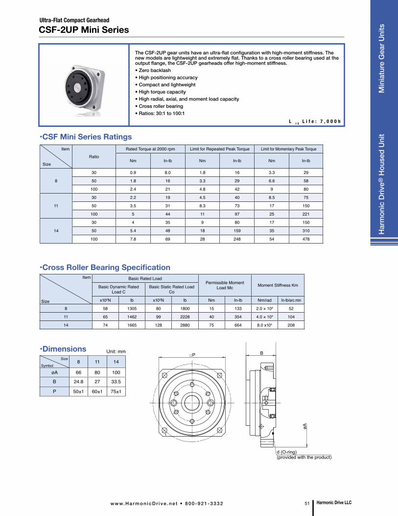
Item
SizeRatio
Rated Torque at 2000 rpm Limit for Repeated Peak Torque Limit for Momentary Peak Torque
Nm In-lb Nm In-lb Nm In-lb
8
30 0.9 8.0 1.8 16 3.3 29
50 1.8 16 3.3 29 6.6 58
100 2.4 21 4.8 42 9 80
11
30 2.2 19 4.5 40 8.5 75
50 3.5 31 8.3 73 17 150
100 5 44 11 97 25 221
14
30 4 35 9 80 17 150
50 5.4 48 18 159 35 310
100 7.8 69 28 248 54 478
Item
Size
Basic Rated LoadPermissible Moment
Load Mc Moment Stiffness KmBasic Dynamic Rated Load C
Basic Static Rated Load Co
x102N lb x102N lb Nm In-lb Nm/rad In-lb/arc.min
8 58 1305 80 1800 15 133 2.0 × 10⁴ 52
11 65 1462 99 2228 40 354 4.0 × 10⁴ 104
14 74 1665 128 2880 75 664 8.0 x10⁴ 208
Ultra-Flat Compact Gearhead
L 1 0 L i f e : 7 , 0 0 0 h
CSF-2UP Mini Series
•Cross Roller Bearing Specification
Size Symbol
8 11 14
øA 66 80 100
B 24.8 27 33.5
P 50±1 60±1 75±1
Unit: mm
The CSF-2UP gear units have an ultra-flat configuration with high-moment stiffness. The new models are lightweight and extremely flat. Thanks to a cross roller bearing used at the output flange, the CSF-2UP gearheads offer high-moment stiffness. • Zero backlash• High positioning accuracy• Compact and lightweight• High torque capacity• High radial, axial, and moment load capacity• Cross roller bearing• Ratios: 30:1 to 100:1
•CSF Mini Series Ratings
•Dimensions
d (O-ring) (provided with the product)
øA
BP
Harmonic Drive LLCw w w. H a r m o n i c D r i v e . n e t • 8 0 0 - 9 2 1 - 3 3 3 2 51
Har
mon
ic D
rive®
Hou
sed
Uni
t M
inia
ture
Gea
r Uni
ts

Incorporating a Harmonic Drive® gear component into an integral housing, the SHF-2UH is a compact hollow shaft gearhead with zero backlash. • Zero backlash• Large hollow thru bore• High positioning accuracy• Compact and simple design• High torque capacity• High torsional stiffness• Shaft input units available (SHF-2UJ)
Gear unit with hollow shaft or solid input shaftSHF-2UH/2UJ Series
L 1 0 L i f e : 7 , 0 0 0 h
SizeSymbol
11 14 17 20 25 32 40 45 50 58
øA 45.3 54 64 75 90 115 140 160 172 201
B 48 52.5 56.5 51.5 55.5 65.5 79 85 93 106
Unit: mm
Item
Size
Basic Rated LoadPermissible Moment Load Mc Moment Stiffness Km
Basic Dynamic Rated Load C Basic Static Rated Load Cox 102N lb x 102N lb Nm In-lb x 104Nm /rad In-lb/arc-min
11 52.9 1189 75.5 1697 74 655 6.5 16714 58 1304 86 1933 74 655 8.5 21917 104 2338 163 3664 124 1097 15.1 38920 146 3282 220 4946 187 1655 25.2 64925 218 4901 358 8048 258 2283 39.2 100932 382 8587 654 14702 580 5133 100 257540 433 9734 816 18344 849 7514 179 460945 776 17444 1350 30348 1127 9974 257 661850 816 18344 1490 33495 1487 13160 351 903858 874 19648 1710 38441 2180 19293 531 13673
•Cross Roller Bearing Specification
• “Basic dynamic rated load” is a constant stationary radial load that achieves a basic dynamic rated life of the bearing of one million revolutions. “Basic static rated load” is a static load that achieves a contact stress of a constant level (408kN/mm2) at the center of a contact zone between the rolling element receiving a maximum load and track.
Item
Size
RatioRated Torque at
2000rpmLimit for
Repeated Peak Torque
Limit for Momentary Peak
TorqueNm In-lb Nm In-lb Nm In-lb
1150 3.5 31 8.3 73 17 150100 5 44 11 97 25 221
14
30 4.0 35 9.0 80 17 15050 5.4 48 18 159 35 31080 7.8 69 23 204 47 416100 7.8 69 28 248 54 478
17
30 8.8 78 6 142 30 26650 16 142 34 301 70 62080 22 195 43 381 87 770100 24 212 54 478 110 974120 24 212 54 478 86 761
20
30 15 133 27 239 50 44350 25 221 56 496 98 86780 34 301 74 655 127 1124100 40 354 82 726 147 1301120 40 354 87 770 147 1301160 40 354 92 814 147 1301
25
30 27 239 50 443 95 84150 39 345 98 867 186 164680 63 558 137 1212 255 2257100 67 593 157 1389 284 2514120 67 593 167 1478 304 2691160 67 593 176 1558 314 2779
•SHF Series RatingsItem
Size
RatioRated Torque at
2000rpmLimit for
Repeated Peak Torque
Limit for Momentary Peak
TorqueNm In-lb Nm In-lb Nm In-lb
32
30 54 478 100 885 200 177050 76 673 216 1912 382 338180 118 1044 230 2036 568 5027100 137 1212 333 2947 647 5726120 137 1212 353 3124 686 6072160 137 1212 372 3292 686 6072
40
50 137 1212 402 3558 686 6072 80 206 1823 519 4593 980 8674 100 265 2345 568 5027 1080 9559 120 294 2602 617 5460 1180 10444 160 294 2602 647 5726 1180 10444
45
50 176 1558 500 4425 950 8408 80 313 2770 706 6248 1270 11240 100 353 3124 755 6682 1570 13896 120 402 3558 823 7284 1760 15577 160 402 3558 882 7806 1910 16905
50
50 245 2168 715 6328 1430 12657 80 372 3292 941 8328 1860 16462 100 470 4160 980 8673 2060 18233 120 529 4682 1080 9558 2060 18233 160 529 4682 1180 10443 2450 21684
58
50 353 3124 1020 9027 1960 17347 80 549 4859 1480 13098 2450 21684 100 686 6160 1590 14072 3180 28145 120 745 6593 1720 15222 3330 29473 160 745 6593 1840 16284 3430 30358
•Dimensions
SHF-2UH
SHF-2UJ
Harmonic Drive LLC 52 w w w. H a r m o n i c D r i v e . n e t • 8 0 0 - 9 2 1 - 3 3 3 2
Har
mon
ic D
rive®
Hou
sed
Uni
t S
HF
Serie
s
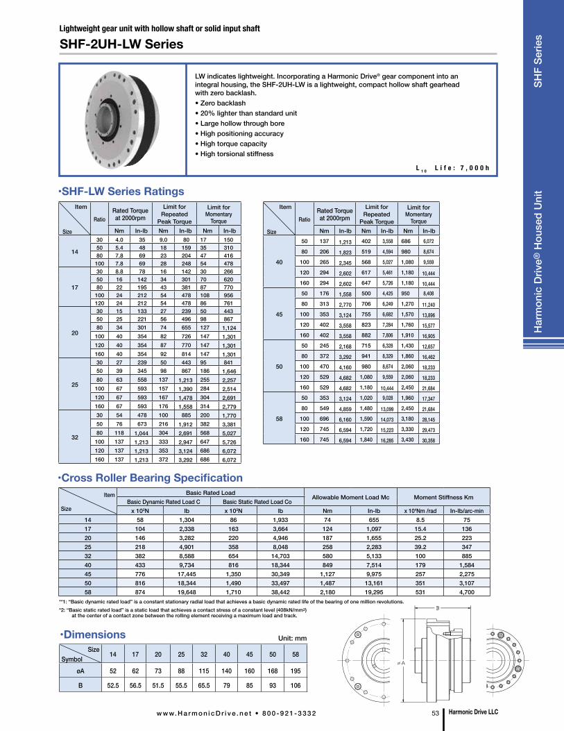
L 1 0 L i f e : 7 , 0 0 0 h
LW indicates lightweight. Incorporating a Harmonic Drive® gear component into an integral housing, the SHF-2UH-LW is a lightweight, compact hollow shaft gearhead with zero backlash. • Zero backlash• 20% lighter than standard unit• Large hollow through bore• High positioning accuracy• High torque capacity• High torsional stiffness
Lightweight gear unit with hollow shaft or solid input shaft
SHF-2UH-LW Series
Size Symbol
14 17 20 25 32 40 45 50 58
øA 52 62 73 88 115 140 160 168 195
B 52.5 56.5 51.5 55.5 65.5 79 85 93 106
Unit: mm
Item
Size
Basic Rated LoadAllowable Moment Load Mc Moment Stiffness Km
Basic Dynamic Rated Load C Basic Static Rated Load Cox 102N lb x 102N lb Nm In-lb x 104Nm /rad In-lb/arc-min
14 58 1,304 86 1,933 74 655 8.5 7517 104 2,338 163 3,664 124 1,097 15.4 13620 146 3,282 220 4,946 187 1,655 25.2 22325 218 4,901 358 8,048 258 2,283 39.2 34732 382 8,588 654 14,703 580 5,133 100 88540 433 9,734 816 18,344 849 7,514 179 1,58445 776 17,445 1,350 30,349 1,127 9,975 257 2,27550 816 18,344 1,490 33,497 1,487 13,161 351 3,10758 874 19,648 1,710 38,442 2,180 19,295 531 4,700
•Cross Roller Bearing Specification
Item
Size
RatioRated Torque at 2000rpm
Limit for Repeated
Peak Torque
Limit for Momentary
TorqueNm In-lb Nm In-lb Nm In-lb
14
30 4.0 35 9.0 80 17 150 50 5.4 48 18 159 35 310 80 7.8 69 23 204 47 416 100 7.8 69 28 248 54 478
17
30 8.8 78 16 142 30 266 50 16 142 34 301 70 620 80 22 195 43 381 87 770 100 24 212 54 478 108 956 120 24 212 54 478 86 761
20
30 15 133 27 239 50 443 50 25 221 56 496 98 867 80 34 301 74 655 127 1,124 100 40 354 82 726 147 1,301 120 40 354 87 770 147 1,301 160 40 354 92 814 147 1,301
25
30 27 239 50 443 95 841 50 39 345 98 867 186 1,646 80 63 558 137 1,213 255 2,257 100 67 593 157 1,390 284 2,514 120 67 593 167 1,478 304 2,691 160 67 593 176 1,558 314 2,779
32
30 54 478 100 885 200 1,770 50 76 673 216 1,912 382 3,381 80 118 1,044 304 2,691 568 5,027 100 137 1,213 333 2,947 647 5,726 120 137 1,213 353 3,124 686 6,072 160 137 1,213 372 3,292 686 6,072
Item
Size
RatioRated Torque at 2000rpm
Limit for Repeated
Peak Torque
Limit for Momentary
TorqueNm In-lb Nm In-lb Nm In-lb
40
50 137 1,213 402 3,558 686 6,072
80 206 1,823 519 4,594 980 8,674
100 265 2,345 568 5,027 1,080 9,559
120 294 2,602 617 5,461 1,180 10,444 160 294 2,602 647 5,726 1,180 10,444
45
50 176 1,558 500 4,425 950 8,408
80 313 2,770 706 6,249 1,270 11,240 100 353 3,124 755 6,682 1,570 13,896 120 402 3,558 823 7,284 1,760 15,577 160 402 3,558 882 7,806 1,910 16,905
50
50 245 2,168 715 6,328 1,430 12,657 80 372 3,292 941 8,329 1,860 16,462 100 470 4,160 980 8,674 2,060 18,233 120 529 4,682 1,080 9,559 2,060 18,233 160 529 4,682 1,180 10,444 2,450 21,684
58
50 353 3,124 1,020 9,028 1,960 17,347 80 549 4,859 1,480 13,099 2,450 21,684 100 696 6,160 1,590 14,073 3,180 28,145 120 745 6,594 1,720 15,223 3,330 29,473 160 745 6,594 1,840 16,285 3,430 30,358
•SHF-LW Series Ratings
**1: “Basic dynamic rated load” is a constant stationary radial load that achieves a basic dynamic rated life of the bearing of one million revolutions. *2: “Basic static rated load” is a static load that achieves a contact stress of a constant level (408kN/mm2) at the center of a contact zone between the rolling element receiving a maximum load and track.
Harmonic Drive LLCw w w. H a r m o n i c D r i v e . n e t • 8 0 0 - 9 2 1 - 3 3 3 2 53
Har
mon
ic D
rive®
Hou
sed
Uni
t S
HF
Serie
s
•Dimensions
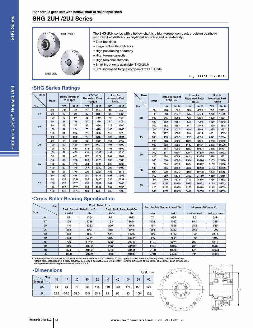
The SHG-2UH series with a hollow shaft is a high torque, compact, precision gearhead with zero backlash and exceptional accuracy and repeatability.• Zero backlash• Large hollow through bore• High positioning accuracy• High torque capacity• High torsional stiffness• Shaft input units available (SHG-2UJ)• 30% increased torque compared to SHF Units
High torque gear unit with hollow shaft or solid input shaft
SHG-2UH /2UJ Series
L 1 0 L i f e : 1 0 , 0 0 0 h
Size Symbol
14 17 20 25 32 40 45 50 58 65
øA 54 64 75 90 115 140 160 175 201 221
B 52.5 56.5 51.5 55.5 65.5 79 85 93 106 128
Unit: mm
Item
Size
Basic Rated LoadPermissible Moment Load Mc Moment Stiffness Km
Basic Dynamic Rated Load C Basic Static Rated Load Cox 102N lb x 102N lb Nm In-lb x 104Nm /rad In-lb/arc-min
14 58 1304 86 1933 74 655 8.5 21917 104 2338 163 3664 124 1097 15.1 38920 146 3282 220 4946 187 1655 25.2 64925 218 4901 358 8048 258 2283 39.2 100932 382 8587 654 14702 580 5133 100 257540 433 9734 816 18344 849 7514 179 460945 776 17444 1350 30348 1127 9974 257 661850 816 18344 1490 33495 1487 13160 351 903858 874 19648 1710 38441 2180 19293 531 1367365 1300 29224 2230 50130 2740 24249 741 19081
• “Basic dynamic rated load” is a constant stationary radial load that achieves a basic dynamic rated life of the bearing of one million revolutions. “Basic static rated load” is a static load that achieves a contact stress of a constant level (408kN/mm2) at the center of a contact zone between the rolling element receiving a maximum load and track.
•Cross Roller Bearing Specification
Item
Size
RatioRated Torque at
2000rpmLimit for
Repeated Peak Torque
Limit for Momentary Peak
TorqueNm In-lb Nm In-lb Nm In-lb
1450 7.0 62 23 204 46 40780 10 89 30 266 61 540100 10 89 36 319 70 620
17
50 21 186 44 389 91 80580 29 257 56 496 113 1000100 31 274 70 620 143 1266120 31 274 70 620 112 991
20
50 33 292 73 646 127 112480 44 389 96 850 165 1460100 52 460 107 947 191 1690120 52 460 113 1000 191 1690160 52 460 120 1062 191 1690
25
50 51 451 127 1124 242 214280 82 726 178 1575 332 2938100 87 770 204 1805 369 3266120 87 770 217 1920 395 3496160 87 770 229 2027 408 3611
32
50 99 876 281 2487 497 439980 153 1354 395 3496 738 6532100 178 1575 433 3832 841 7443120 178 1575 459 4062 892 7895160 178 1575 484 4283 892 7895
Item
Size
RatioRated Torque at
2000rpmLimit for
Repeated Peak Torque
Limit for Momentary Peak
TorqueNm In-lb Nm In-lb Nm In-lb
40
50 178 1575 523 4629 892 789580 268 2372 675 5974 1270 11240100 345 3053 738 6531 1400 12391120 382 3381 802 7098 1530 13542160 382 3381 841 7443 1530 13542
45
50 229 2027 650 5753 1235 1093180 407 3602 918 8124 1651 14613100 459 4062 982 8691 2041 18064120 523 4629 1070 9470 2288 20250160 523 4629 1147 10151 2483 21976
50
80 484 4283 1223 10824 2418 21401100 611 5407 1274 11275 2678 23702120 688 6089 1404 12425 2678 23702160 688 6089 1534 13576 3185 28190
58
80 714 6319 1924 17027 3185 28190100 905 8009 2067 18293 4134 36589120 969 8576 2236 19789 4329 38315160 969 8576 2392 21169 4459 39465
65
80 969 8576 2743 24276 4836 42802100 1236 10939 2990 26462 6175 54653120 1236 10939 3263 28878 6175 54653160 1236 10939 3419 30258 6175 54653
•SHG Series Ratings
•Dimensions
SHG-2UH
SHG-2UJ
Harmonic Drive LLC 54 w w w. H a r m o n i c D r i v e . n e t • 8 0 0 - 9 2 1 - 3 3 3 2
Har
mon
ic D
rive®
Hou
sed
Uni
t S
HG
Ser
ies
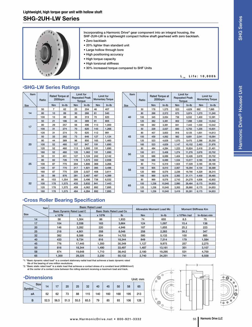
Incorporating a Harmonic Drive® gear component into an integral housing, the SHF-2UH-LW is a lightweight compact hollow shaft gearhead with zero backlash. • Zero backlash• 20% lighter than standard unit• Large hollow through bore• High positioning accuracy• High torque capacity• High torsional stiffness• 30% increased torque compared to SHF Units
Lightweight, high torque gear unit with hollow shaft
SHG-2UH-LW Series
Item
Size
Basic Rated LoadAllowable Moment Load Mc Moment Stiffness Km
Basic Dynamic Rated Load C Basic Static Rated Load Cox 102N lb x 102N lb Nm In-lb x 104Nm /rad In-lb/arc-min
14 58 1,304 86 1,933 74 655 8.5 7517 104 2,338 163 3,664 124 1,097 15.4 13620 146 3,282 220 4,946 187 1,655 25.2 22325 218 4,901 358 8,048 258 2,283 39.2 34732 382 8,588 654 14,703 580 5,133 100 88540 433 9,734 816 18,344 849 7,514 179 1,58445 776 17,445 1,350 30,349 1,127 9,975 257 2,27550 816 18,344 1,490 33,497 1,487 13,161 351 3,10758 874 19,648 1,710 38,442 2,180 19,295 531 4,70065 1,300 29,225 2,230 50,132 2,740 24,251 741 6,558
*1: “Basic dynamic rated load” is a constant stationary radial load that achieves a basic dynamic rated life of the bearing of one million revolutions. *2: “Basic static rated load” is a static load that achieves a contact stress of a constant level (408kN/mm2) at the center of a contact zone between the rolling element receiving a maximum load and track.
•Cross Roller Bearing Specification
Item
Size
RatioRated Torque at
2000rpmLimit for
Repeated Peak Torque
Limit for Momentary Torque
Nm In-lb Nm In-lb Nm In-lb
1450 7 62 23 204 46 40780 10 89 30 266 61 540100 10 89 36 319 70 620
17
50 21 186 44 389 91 80580 29 257 56 496 113 1,000100 31 274 70 620 143 1,266120 31 274 70 620 112 991
20
50 33 292 73 646 127 1,12480 44 389 96 850 165 1,460100 52 460 107 947 191 1,690120 52 460 113 1,000 191 1,690160 52 460 120 1,062 191 1,690
25
50 51 451 127 1,124 242 2,14280 82 726 178 1,575 332 2,938100 87 770 204 1,806 369 3,266120 87 770 217 1,921 395 3,496160 87 770 229 2,027 408 3,611
32
50 99 876 281 2,487 497 4,39980 153 1,354 395 3,496 738 6,532100 178 1,575 433 3,832 841 7,443120 178 1,575 459 4,062 892 7,895160 178 1,575 484 4,284 892 7,895
Item
Size
RatioRated Torque at
2000rpmLimit for
Repeated Peak Torque
Limit for Momentary Torque
Nm In-lb Nm In-lb Nm In-lb
40
50 178 1,575 523 4,629 892 7,89580 268 2,372 675 5,974 1,270 11,240100 345 3,054 738 6,532 1,400 12,391120 382 3,381 802 7,098 1,530 13,542160 382 3,381 841 7,443 1,530 13,542
45
50 229 2,027 650 5,753 1,235 10,93180 407 3,602 918 8,125 1,651 14,613100 459 4,062 982 8,691 2,041 18,064120 523 4,629 1,070 9,470 2,288 20,250160 523 4,629 1,147 10,152 2,483 21,976
50
80 484 4,284 1,223 10,824 2,418 21,401100 611 5,408 1,274 11,276 2,678 23,702120 688 6,089 1,404 12,426 2,678 23,702160 688 6,089 1,534 13,577 3,185 28,190
58
80 714 6,319 1,924 17,029 3,185 28,190100 905 8,010 2,067 18,294 4,134 36,589120 969 8,576 2,236 19,790 4,329 38,315160 969 8,576 2,392 21,171 4,459 39,465
65
80 969 8,576 2,743 24,278 4,836 42,802100 1,236 10,940 2,990 26,464 6,175 54,653120 1,236 10,940 3,263 28,880 6,175 54,653160 1,236 10,940 3,419 30,261 6,175 54,653
•SHG-LW Series Ratings
Size Symbol
14 17 20 25 32 40 45 50 58 65
øA 52 62 73 88 115 140 160 168 195 213
B 52.5 56.5 51.5 55.5 65.5 79 85 93 106 128
Unit: mm•Dimensions
Harmonic Drive LLCw w w. H a r m o n i c D r i v e . n e t • 8 0 0 - 9 2 1 - 3 3 3 2 55
Har
mon
ic D
rive®
Hou
sed
Uni
t S
HG
Ser
ies
L 1 0 L i f e : 1 0 , 0 0 0 h
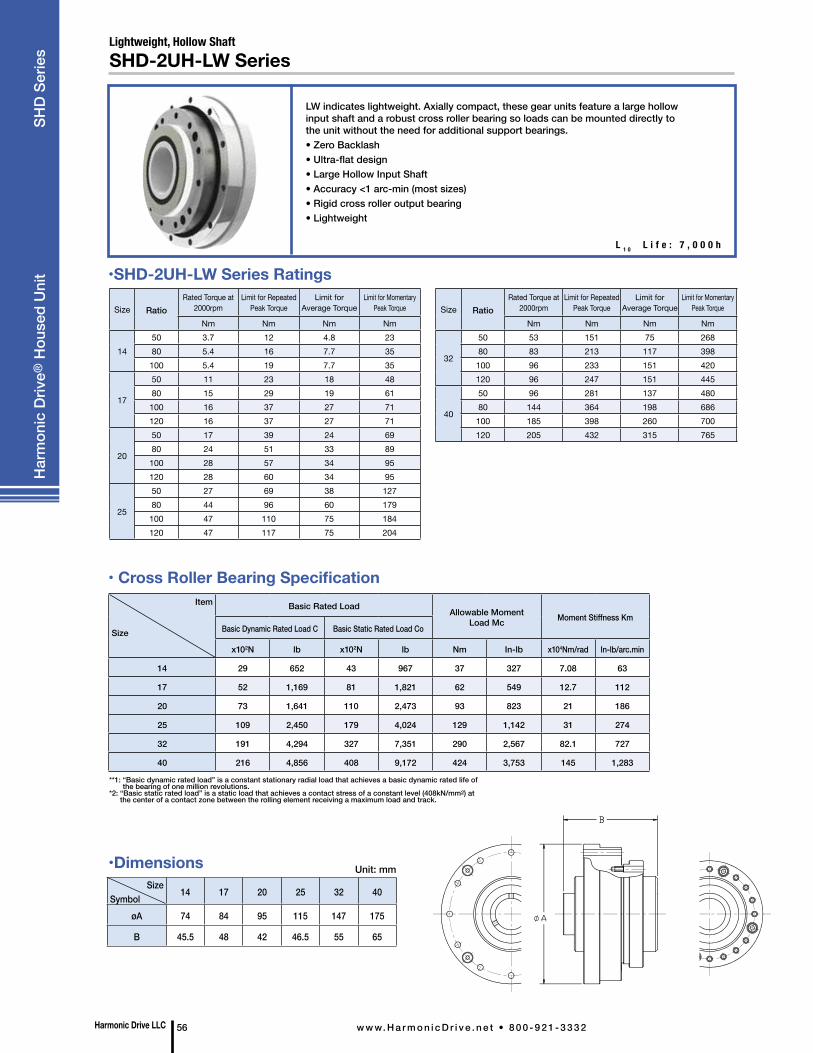
•SHD-2UH-LW Series Ratings
Size Symbol
14 17 20 25 32 40
øA 74 84 95 115 147 175
B 45.5 48 42 46.5 55 65
Unit: mm
• Cross Roller Bearing SpecificationItem
Size
Basic Rated Load Allowable Moment Load Mc Moment Stiffness Km
Basic Dynamic Rated Load C Basic Static Rated Load Co
x102N lb x102N lb Nm In-lb x104Nm/rad In-lb/arc.min
14 29 652 43 967 37 327 7.08 63
17 52 1,169 81 1,821 62 549 12.7 112
20 73 1,641 110 2,473 93 823 21 186
25 109 2,450 179 4,024 129 1,142 31 274
32 191 4,294 327 7,351 290 2,567 82.1 727
40 216 4,856 408 9,172 424 3,753 145 1,283
Lightweight, Hollow ShaftSHD-2UH-LW Series
LW indicates lightweight. Axially compact, these gear units feature a large hollow input shaft and a robust cross roller bearing so loads can be mounted directly to the unit without the need for additional support bearings.• Zero Backlash• Ultra-flat design • Large Hollow Input Shaft • Accuracy <1 arc-min (most sizes)• Rigid cross roller output bearing• Lightweight
**1: “Basic dynamic rated load” is a constant stationary radial load that achieves a basic dynamic rated life of the bearing of one million revolutions.
*2: “Basic static rated load” is a static load that achieves a contact stress of a constant level (408kN/mm2) at the center of a contact zone between the rolling element receiving a maximum load and track.
L 1 0 L i f e : 7 , 0 0 0 h
•Dimensions
Size RatioRated Torque at
2000rpmLimit for Repeated
Peak TorqueLimit for
Average TorqueLimit for Momentary
Peak Torque
Nm Nm Nm Nm
1450 3.7 12 4.8 2380 5.4 16 7.7 35
100 5.4 19 7.7 35
17
50 11 23 18 4880 15 29 19 61
100 16 37 27 71120 16 37 27 71
20
50 17 39 24 6980 24 51 33 89
100 28 57 34 95120 28 60 34 95
25
50 27 69 38 12780 44 96 60 179
100 47 110 75 184120 47 117 75 204
Size RatioRated Torque at
2000rpmLimit for Repeated
Peak TorqueLimit for
Average TorqueLimit for Momentary
Peak Torque
Nm Nm Nm Nm
32
50 53 151 75 26880 83 213 117 398100 96 233 151 420120 96 247 151 445
40
50 96 281 137 48080 144 364 198 686100 185 398 260 700120 205 432 315 765
Harmonic Drive LLC 56 w w w. H a r m o n i c D r i v e . n e t • 8 0 0 - 9 2 1 - 3 3 3 2
Har
mon
ic D
rive®
Hou
sed
Uni
t
SH
D S
erie
s
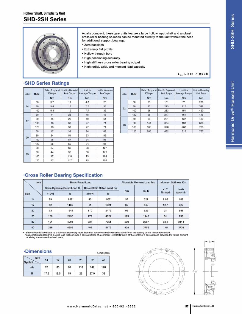
•Dimensions
Size RatioRated Torque at
2000rpmLimit for Repeated
Peak TorqueLimit for
Average TorqueLimit for Momentary
Peak Torque
Nm Nm Nm Nm
1450 3.7 12 4.8 2380 5.4 16 7.7 35
100 5.4 19 7.7 35
17
50 11 23 18 4880 15 29 19 61
100 16 37 27 71120 16 37 27 71
20
50 17 39 24 6980 24 51 33 89
100 28 57 34 95120 28 60 34 95
25
50 27 69 38 12780 44 96 60 179
100 47 110 75 184120 47 117 75 204
Size RatioRated Torque at
2000rpmLimit for Repeated
Peak TorqueLimit for
Average TorqueLimit for Momentary
Peak Torque
Nm Nm Nm Nm
32
50 53 151 75 26880 83 213 117 398100 96 233 151 420120 96 247 151 445
40
50 96 281 137 48080 144 364 198 686100 185 398 260 700120 205 432 315 765
Harmonic Drive LLCw w w. H a r m o n i c D r i v e . n e t • 8 0 0 - 9 2 1 - 3 3 3 2 57
Item
Size
Basic Rated Load Allowable Moment Load Mc Moment Stiffness Km
Basic Dynamic Rated Load C Basic Static Rated Load CoNm In-lb x104
Nm/radIn-lb
/arc-minx102N lb x102N lb
14 29 652 43 967 37 327 7.08 182
17 52 1169 81 1821 62 549 12.7 327
20 73 1641 110 2473 93 823 21 541
25 109 2450 179 4024 129 1142 31 798
32 191 4294 327 7351 290 2567 82.1 2114
40 216 4856 408 9172 424 3752 145 3734
•SHD Series Ratings
•Cross Roller Bearing Specification
L 1 0 L i f e : 7 , 0 0 0 h
Size Symbol
14 17 20 25 32 40
øA 70 80 90 110 142 170
B 17.5 18.5 19 22 27.9 33
Unit: mm
Hollow Shaft, Simplicity Unit
SHD-2SH Series
Axially compact, these gear units feature a large hollow input shaft and a robust cross roller bearing so loads can be mounted directly to the unit without the need for additional support bearings.• Zero backlash • Extremely flat profile• Hollow through bore• High positioning accuracy• High stiffness cross roller bearing output• High radial, axial, and moment load capacity
• “Basic dynamic rated load” is a constant stationary radial load that achieves a basic dynamic rated life of the bearing of one million revolutions. “ Basic static rated load” is a static load that achieves a contact stress of a constant level (4kN/mm2) at the center of a contact zone between the rolling element receiving a maximum load and track.
Har
mon
ic D
rive®
Hou
sed
Uni
t SH
D-2
SH S
erie
s
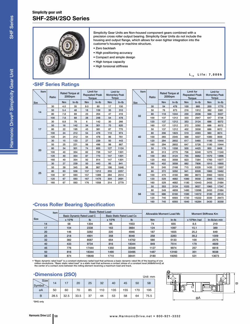
Harmonic Drive LLC 58 w w w. H a r m o n i c D r i v e . n e t • 8 0 0 - 9 2 1 - 3 3 3 2
Har
mon
ic D
rive®
Sim
plic
ity G
ear U
nit
SH
F Se
ries
Simplicity Gear Units are Non-housed component gears combined with a precision cross roller output bearing. Simplicity Gear Units do not include the housing and output flange, which allows for even tighter integration into the customer’s housing or machine structure. • Zero backlash• High positioning accuracy• Compact and simple design• High torque capacity• High torsional stiffness
Simplicity gear unitSHF-2SH/2SO Series
L 1 0 L i f e : 7 , 0 0 0 h
SizeSymbol
14 17 20 25 32 40 45 50 58
øA 50 60 70 85 110 135 155 170 195
B 28.5 32.5 33.5 37 44 53 58 64 75.5
Unit: mm
Item
Size
Basic Rated LoadAllowable Moment Load Mc Moment Stiffness Km
Basic Dynamic Rated Load C Basic Static Rated Load Cox 102N lb x 102N lb Nm In-lb x 104Nm /rad In-lb/arc-min
14 58 1304 86 1933 74 655 8.5 21917 104 2338 163 3664 124 1097 15.1 38920 146 3282 220 4946 187 1655 25.2 64925 218 4901 358 8048 258 2283 39.2 100932 382 8587 654 14702 580 5133 100 257540 433 9734 816 18344 849 7514 179 460945 776 17444 1350 30348 1127 9974 257 661850 816 18344 1490 33495 1487 13160 351 903858 874 19648 1710 38441 2180 19293 531 13673
•Cross Roller Bearing Specification
• “Basic dynamic rated load” is a constant stationary radial load that achieves a basic dynamic rated life of the bearing of one million revolutions. “Basic static rated load” is a static load that achieves a contact stress of a constant level (408kN/mm2) at the center of a contact zone between the rolling element receiving a maximum load and track.
*SHG only
Item
Size
RatioRated Torque at
2000rpmLimit for
Repeated Peak Torque
Limit for Momentary Peak
TorqueNm In-lb Nm In-lb Nm In-lb
14
30 4.0 35 9.0 80 17 15050 5.4 48 18 159 35 31080 7.8 69 23 204 47 416100 7.8 69 28 248 54 478
17
30 8.8 78 6 142 30 26650 16 142 34 301 70 62080 22 195 43 381 87 770100 24 212 54 478 110 974120 24 212 54 478 86 761
20
30 15 133 27 239 50 44350 25 221 56 496 98 86780 34 301 74 655 127 1124100 40 354 82 726 147 1301120 40 354 87 770 147 1301160 40 354 92 814 147 1301
25
30 27 239 50 443 95 84150 39 345 98 867 186 164680 63 558 137 1212 255 2257100 67 593 157 1389 284 2514120 67 593 167 1478 304 2691160 67 593 176 1558 314 2779
•SHF Series RatingsItem
Size
RatioRated Torque at
2000rpmLimit for
Repeated Peak Torque
Limit for Momentary Peak
TorqueNm In-lb Nm In-lb Nm In-lb
32
30 54 478 100 885 200 177050 76 673 216 1912 382 338180 118 1044 230 2036 568 5027100 137 1212 333 2947 647 5726120 137 1212 353 3124 686 6072160 137 1212 372 3292 686 6072
40
50 137 1212 402 3558 686 6072 80 206 1823 519 4593 980 8674 100 265 2345 568 5027 1080 9559 120 294 2602 617 5460 1180 10444 160 294 2602 647 5726 1180 10444
45
50 176 1558 500 4425 950 8408 80 313 2770 706 6248 1270 11240 100 353 3124 755 6682 1570 13896 120 402 3558 823 7284 1760 15577 160 402 3558 882 7806 1910 16905
50
50 245 2168 715 6328 1430 12657 80 372 3292 941 8328 1860 16462 100 470 4160 980 8673 2060 18233 120 529 4682 1080 9558 2060 18233 160 529 4682 1180 10443 2450 21684
58
50 353 3124 1020 9027 1960 17347 80 549 4859 1480 13098 2450 21684 100 686 6160 1590 14072 3180 28145 120 745 6593 1720 15222 3330 29473 160 745 6593 1840 16284 3430 30358
•Dimensions (2SO)
φA
B
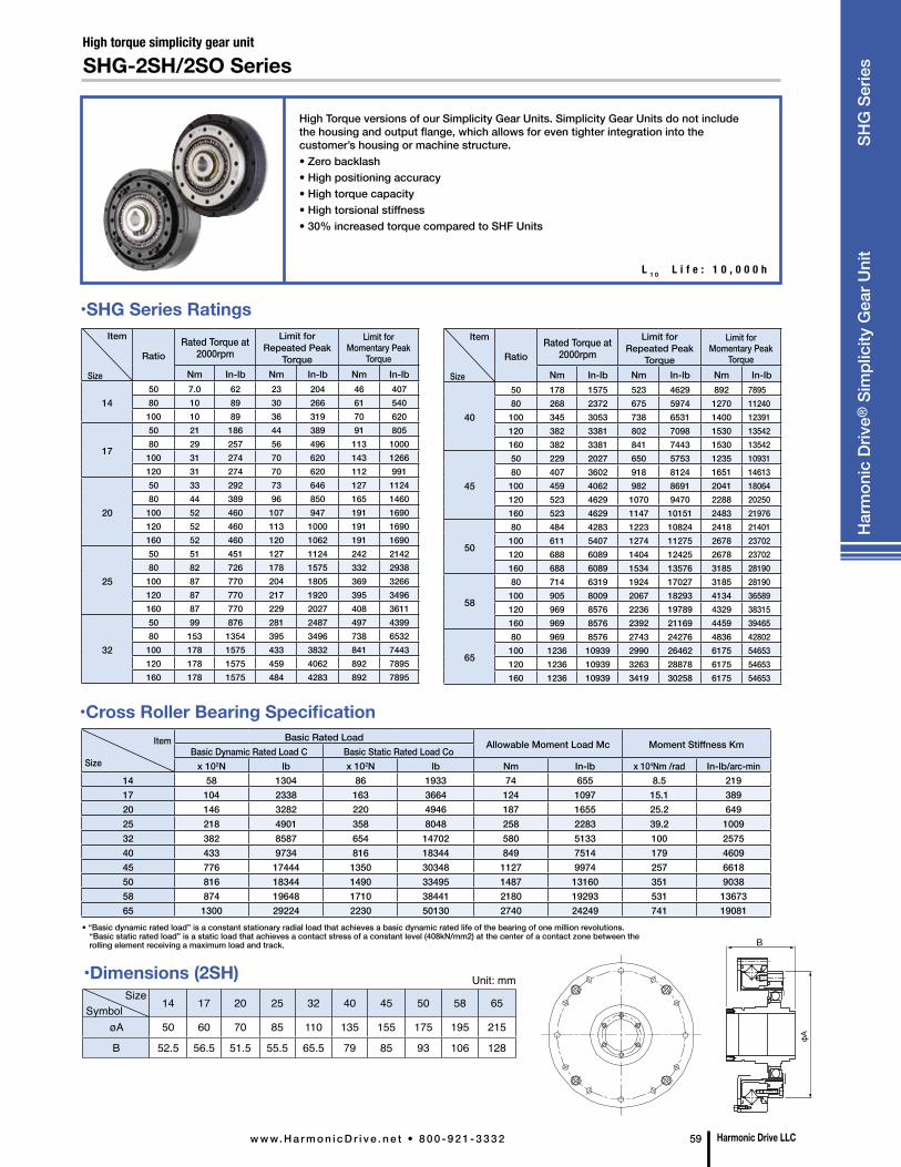
Harmonic Drive LLCw w w. H a r m o n i c D r i v e . n e t • 8 0 0 - 9 2 1 - 3 3 3 2 59
High Torque versions of our Simplicity Gear Units. Simplicity Gear Units do not include the housing and output flange, which allows for even tighter integration into the customer’s housing or machine structure.• Zero backlash• High positioning accuracy• High torque capacity• High torsional stiffness• 30% increased torque compared to SHF Units
High torque simplicity gear unit
SHG-2SH/2SO Series
L 1 0 L i f e : 1 0 , 0 0 0 h
Size Symbol
14 17 20 25 32 40 45 50 58 65
øA 50 60 70 85 110 135 155 175 195 215
B 52.5 56.5 51.5 55.5 65.5 79 85 93 106 128
Unit: mm
Item
Size
Basic Rated LoadAllowable Moment Load Mc Moment Stiffness Km
Basic Dynamic Rated Load C Basic Static Rated Load Cox 102N lb x 102N lb Nm In-lb x 104Nm /rad In-lb/arc-min
14 58 1304 86 1933 74 655 8.5 21917 104 2338 163 3664 124 1097 15.1 38920 146 3282 220 4946 187 1655 25.2 64925 218 4901 358 8048 258 2283 39.2 100932 382 8587 654 14702 580 5133 100 257540 433 9734 816 18344 849 7514 179 460945 776 17444 1350 30348 1127 9974 257 661850 816 18344 1490 33495 1487 13160 351 903858 874 19648 1710 38441 2180 19293 531 1367365 1300 29224 2230 50130 2740 24249 741 19081
• “Basic dynamic rated load” is a constant stationary radial load that achieves a basic dynamic rated life of the bearing of one million revolutions. “Basic static rated load” is a static load that achieves a contact stress of a constant level (408kN/mm2) at the center of a contact zone between the rolling element receiving a maximum load and track.
•Cross Roller Bearing Specification
Item
Size
RatioRated Torque at
2000rpmLimit for
Repeated Peak Torque
Limit for Momentary Peak
TorqueNm In-lb Nm In-lb Nm In-lb
1450 7.0 62 23 204 46 40780 10 89 30 266 61 540100 10 89 36 319 70 620
17
50 21 186 44 389 91 80580 29 257 56 496 113 1000100 31 274 70 620 143 1266120 31 274 70 620 112 991
20
50 33 292 73 646 127 112480 44 389 96 850 165 1460100 52 460 107 947 191 1690120 52 460 113 1000 191 1690160 52 460 120 1062 191 1690
25
50 51 451 127 1124 242 214280 82 726 178 1575 332 2938100 87 770 204 1805 369 3266120 87 770 217 1920 395 3496160 87 770 229 2027 408 3611
32
50 99 876 281 2487 497 439980 153 1354 395 3496 738 6532100 178 1575 433 3832 841 7443120 178 1575 459 4062 892 7895160 178 1575 484 4283 892 7895
Item
Size
RatioRated Torque at
2000rpmLimit for
Repeated Peak Torque
Limit for Momentary Peak
TorqueNm In-lb Nm In-lb Nm In-lb
40
50 178 1575 523 4629 892 789580 268 2372 675 5974 1270 11240100 345 3053 738 6531 1400 12391120 382 3381 802 7098 1530 13542160 382 3381 841 7443 1530 13542
45
50 229 2027 650 5753 1235 1093180 407 3602 918 8124 1651 14613100 459 4062 982 8691 2041 18064120 523 4629 1070 9470 2288 20250160 523 4629 1147 10151 2483 21976
50
80 484 4283 1223 10824 2418 21401100 611 5407 1274 11275 2678 23702120 688 6089 1404 12425 2678 23702160 688 6089 1534 13576 3185 28190
58
80 714 6319 1924 17027 3185 28190100 905 8009 2067 18293 4134 36589120 969 8576 2236 19789 4329 38315160 969 8576 2392 21169 4459 39465
65
80 969 8576 2743 24276 4836 42802100 1236 10939 2990 26462 6175 54653120 1236 10939 3263 28878 6175 54653160 1236 10939 3419 30258 6175 54653
•SHG Series Ratings
•Dimensions (2SH)
Har
mon
ic D
rive®
Sim
plic
ity G
ear U
nit
SH
G S
erie
s
B
φA
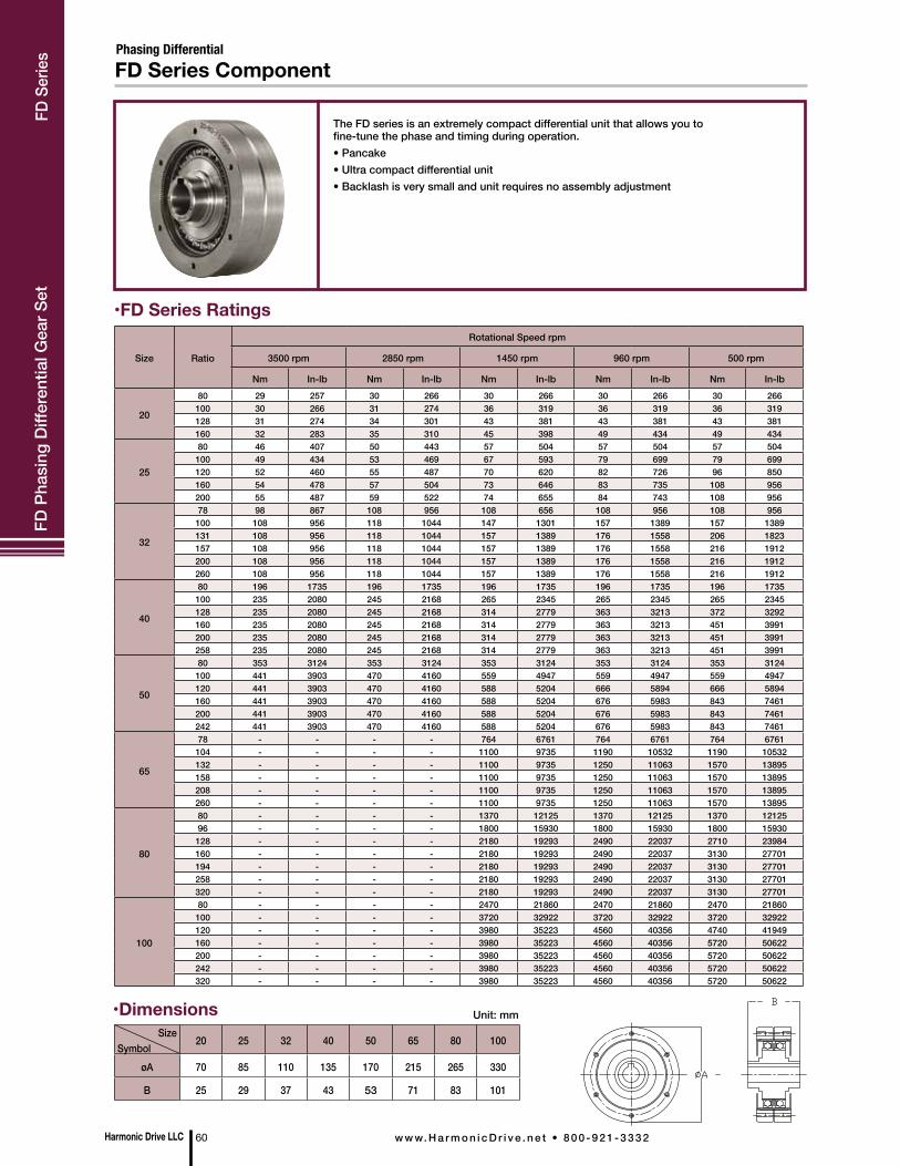
Phasing Differential
The FD series is an extremely compact differential unit that allows you to fine-tune the phase and timing during operation. • Pancake• Ultra compact differential unit• Backlash is very small and unit requires no assembly adjustment
•FD Series Ratings
Size Ratio
Rotational Speed rpm
3500 rpm 2850 rpm 1450 rpm 960 rpm 500 rpm
Nm In-lb Nm In-lb Nm In-lb Nm In-lb Nm In-lb
20
80 29 257 30 266 30 266 30 266 30 266100 30 266 31 274 36 319 36 319 36 319128 31 274 34 301 43 381 43 381 43 381160 32 283 35 310 45 398 49 434 49 434
25
80 46 407 50 443 57 504 57 504 57 504100 49 434 53 469 67 593 79 699 79 699120 52 460 55 487 70 620 82 726 96 850160 54 478 57 504 73 646 83 735 108 956200 55 487 59 522 74 655 84 743 108 956
32
78 98 867 108 956 108 656 108 956 108 956100 108 956 118 1044 147 1301 157 1389 157 1389131 108 956 118 1044 157 1389 176 1558 206 1823157 108 956 118 1044 157 1389 176 1558 216 1912200 108 956 118 1044 157 1389 176 1558 216 1912260 108 956 118 1044 157 1389 176 1558 216 1912
40
80 196 1735 196 1735 196 1735 196 1735 196 1735100 235 2080 245 2168 265 2345 265 2345 265 2345128 235 2080 245 2168 314 2779 363 3213 372 3292160 235 2080 245 2168 314 2779 363 3213 451 3991200 235 2080 245 2168 314 2779 363 3213 451 3991258 235 2080 245 2168 314 2779 363 3213 451 3991
50
80 353 3124 353 3124 353 3124 353 3124 353 3124100 441 3903 470 4160 559 4947 559 4947 559 4947120 441 3903 470 4160 588 5204 666 5894 666 5894160 441 3903 470 4160 588 5204 676 5983 843 7461200 441 3903 470 4160 588 5204 676 5983 843 7461242 441 3903 470 4160 588 5204 676 5983 843 7461
65
78 - - - - 764 6761 764 6761 764 6761104 - - - - 1100 9735 1190 10532 1190 10532132 - - - - 1100 9735 1250 11063 1570 13895158 - - - - 1100 9735 1250 11063 1570 13895208 - - - - 1100 9735 1250 11063 1570 13895260 - - - - 1100 9735 1250 11063 1570 13895
80
80 - - - - 1370 12125 1370 12125 1370 1212596 - - - - 1800 15930 1800 15930 1800 15930
128 - - - - 2180 19293 2490 22037 2710 23984160 - - - - 2180 19293 2490 22037 3130 27701194 - - - - 2180 19293 2490 22037 3130 27701258 - - - - 2180 19293 2490 22037 3130 27701320 - - - - 2180 19293 2490 22037 3130 27701
100
80 - - - - 2470 21860 2470 21860 2470 21860100 - - - - 3720 32922 3720 32922 3720 32922120 - - - - 3980 35223 4560 40356 4740 41949160 - - - - 3980 35223 4560 40356 5720 50622200 - - - - 3980 35223 4560 40356 5720 50622242 - - - - 3980 35223 4560 40356 5720 50622320 - - - - 3980 35223 4560 40356 5720 50622
Size Symbol
20 25 32 40 50 65 80 100
øA 70 85 110 135 170 215 265 330
B 25 29 37 43 53 71 83 101
Unit: mm•Dimensions
Harmonic Drive LLC 60 w w w. H a r m o n i c D r i v e . n e t • 8 0 0 - 9 2 1 - 3 3 3 2
FD P
hasi
ng D
iffer
entia
l Gea
r Set
FD Series ComponentFD
Ser
ies
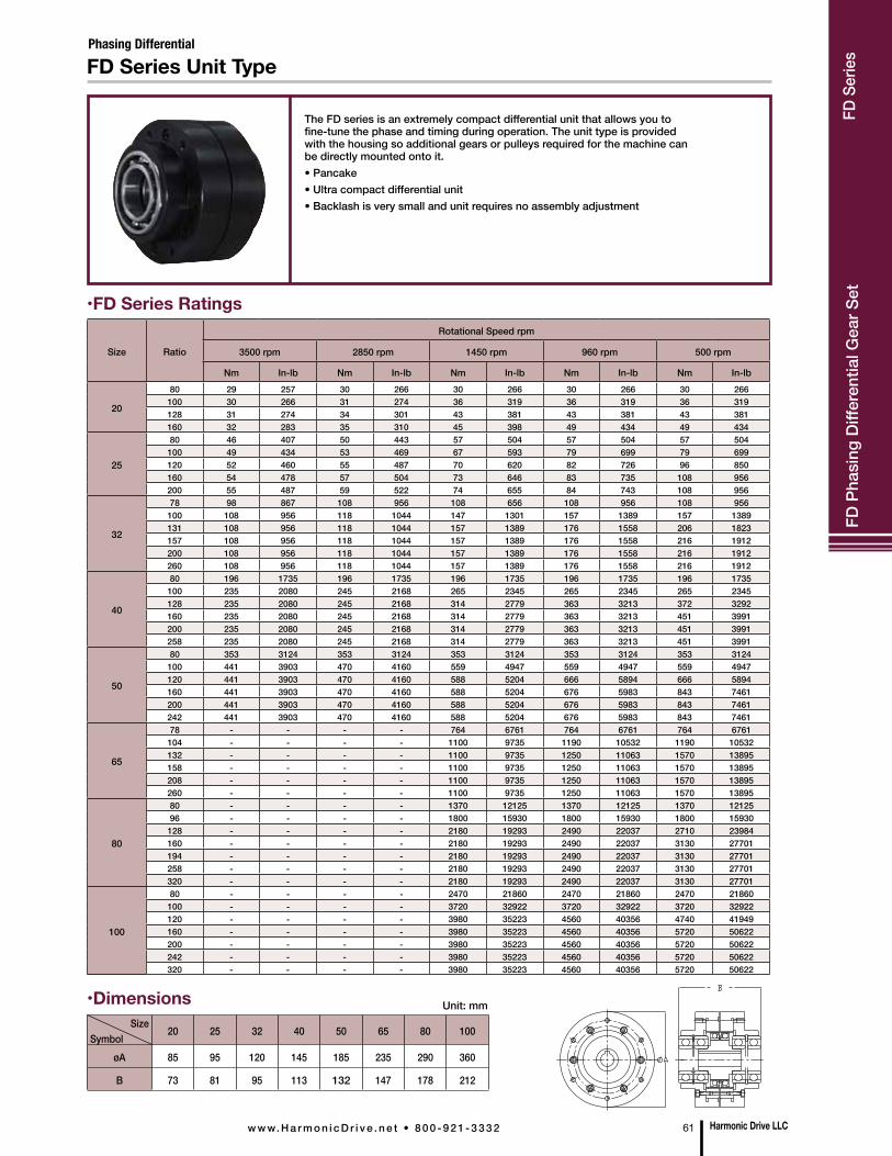
The FD series is an extremely compact differential unit that allows you to fine-tune the phase and timing during operation. The unit type is provided with the housing so additional gears or pulleys required for the machine can be directly mounted onto it.• Pancake• Ultra compact differential unit• Backlash is very small and unit requires no assembly adjustment
•FD Series Ratings
•Dimensions
Size Ratio
Rotational Speed rpm
3500 rpm 2850 rpm 1450 rpm 960 rpm 500 rpm
Nm In-lb Nm In-lb Nm In-lb Nm In-lb Nm In-lb
20
80 29 257 30 266 30 266 30 266 30 266100 30 266 31 274 36 319 36 319 36 319128 31 274 34 301 43 381 43 381 43 381160 32 283 35 310 45 398 49 434 49 434
25
80 46 407 50 443 57 504 57 504 57 504100 49 434 53 469 67 593 79 699 79 699120 52 460 55 487 70 620 82 726 96 850160 54 478 57 504 73 646 83 735 108 956200 55 487 59 522 74 655 84 743 108 956
32
78 98 867 108 956 108 656 108 956 108 956100 108 956 118 1044 147 1301 157 1389 157 1389131 108 956 118 1044 157 1389 176 1558 206 1823157 108 956 118 1044 157 1389 176 1558 216 1912200 108 956 118 1044 157 1389 176 1558 216 1912260 108 956 118 1044 157 1389 176 1558 216 1912
40
80 196 1735 196 1735 196 1735 196 1735 196 1735100 235 2080 245 2168 265 2345 265 2345 265 2345128 235 2080 245 2168 314 2779 363 3213 372 3292160 235 2080 245 2168 314 2779 363 3213 451 3991200 235 2080 245 2168 314 2779 363 3213 451 3991258 235 2080 245 2168 314 2779 363 3213 451 3991
50
80 353 3124 353 3124 353 3124 353 3124 353 3124100 441 3903 470 4160 559 4947 559 4947 559 4947120 441 3903 470 4160 588 5204 666 5894 666 5894160 441 3903 470 4160 588 5204 676 5983 843 7461200 441 3903 470 4160 588 5204 676 5983 843 7461242 441 3903 470 4160 588 5204 676 5983 843 7461
65
78 - - - - 764 6761 764 6761 764 6761104 - - - - 1100 9735 1190 10532 1190 10532132 - - - - 1100 9735 1250 11063 1570 13895158 - - - - 1100 9735 1250 11063 1570 13895208 - - - - 1100 9735 1250 11063 1570 13895260 - - - - 1100 9735 1250 11063 1570 13895
80
80 - - - - 1370 12125 1370 12125 1370 1212596 - - - - 1800 15930 1800 15930 1800 15930
128 - - - - 2180 19293 2490 22037 2710 23984160 - - - - 2180 19293 2490 22037 3130 27701194 - - - - 2180 19293 2490 22037 3130 27701258 - - - - 2180 19293 2490 22037 3130 27701320 - - - - 2180 19293 2490 22037 3130 27701
100
80 - - - - 2470 21860 2470 21860 2470 21860100 - - - - 3720 32922 3720 32922 3720 32922120 - - - - 3980 35223 4560 40356 4740 41949160 - - - - 3980 35223 4560 40356 5720 50622200 - - - - 3980 35223 4560 40356 5720 50622242 - - - - 3980 35223 4560 40356 5720 50622320 - - - - 3980 35223 4560 40356 5720 50622
Size Symbol
20 25 32 40 50 65 80 100
øA 85 95 120 145 185 235 290 360
B 73 81 95 113 132 147 178 212
Unit: mm
Harmonic Drive LLCw w w. H a r m o n i c D r i v e . n e t • 8 0 0 - 9 2 1 - 3 3 3 2 61
FD P
hasi
ng D
iffer
entia
l Gea
r Set
FD Series Unit TypePhasing Differential
FD S
erie
s
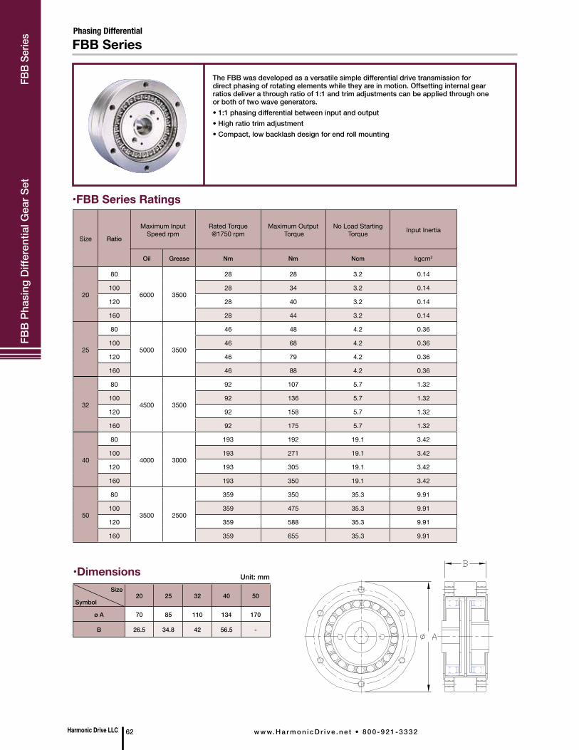
Harmonic Drive LLC 62 w w w. H a r m o n i c D r i v e . n e t • 8 0 0 - 9 2 1 - 3 3 3 2
The FBB was developed as a versatile simple differential drive transmission for direct phasing of rotating elements while they are in motion. Offsetting internal gear ratios deliver a through ratio of 1:1 and trim adjustments can be applied through one or both of two wave generators.• 1:1 phasing differential between input and output• High ratio trim adjustment• Compact, low backlash design for end roll mounting
Size
Symbol20 25 32 40 50
ø A 70 85 110 134 170
B 26.5 34.8 42 56.5 -
Unit: mm
Size Ratio
Maximum Input Speed rpm
Rated Torque @1750 rpm
Maximum Output Torque
No Load Starting Torque Input Inertia
Oil Grease Nm Nm Ncm kgcm2
20
80
6000 3500
28 28 3.2 0.14
100 28 34 3.2 0.14
120 28 40 3.2 0.14
160 28 44 3.2 0.14
25
80
5000 3500
46 48 4.2 0.36
100 46 68 4.2 0.36
120 46 79 4.2 0.36
160 46 88 4.2 0.36
32
80
4500 3500
92 107 5.7 1.32
100 92 136 5.7 1.32
120 92 158 5.7 1.32
160 92 175 5.7 1.32
40
80
4000 3000
193 192 19.1 3.42
100 193 271 19.1 3.42
120 193 305 19.1 3.42
160 193 350 19.1 3.42
50
80
3500 2500
359 350 35.3 9.91
100 359 475 35.3 9.91
120 359 588 35.3 9.91
160 359 655 35.3 9.91
•FBB Series Ratings
•Dimensions
Hea
der
FBB
Phas
ing
Diff
eren
tial G
ear S
et
FBB SeriesPhasing Differential
FBB
Serie
s

HDI Size Bore Size O.D. Length Torque Capacity
-101/2”5/8”3/4”
23/8”(60.33mm)
111/16”(42.9mm)
1000 lb-in(113 Nm)
-253/4”1”
3”(76.2mm)
2 3/16”(76.2mm)
2500 lb-in(283 Nm)
-50 11/4” 33/4”(95.3mm)
2 3/8”(95.3mm
5000 lb-in(565 Nm
•3 Models, 6 Bore Sizes Available From Stock
Input
Output
To operate, hand rotate the adjusting ring in either direction to produce a 100:1 reduction between the ring and the output. Adjust the friction adjustment/locking screw to desired resistance. For some applications, one adjustment will be sufficient for both shaft turning and phase adjusting modes. For more severe loading, such as hard stops or high peak torque situations, the friction adjustment/locking screw may be used to lock the adjusting ring in place to maintain phase.
Infinit-Indexer® phase adjusters are available from immediate stock in the standard bore sizes shown with keyways, set screws, and tapped holes for face mounting of either hub. It is possible for the user to modify these configurations by disassembling the unit. The hub material is low carbon steel with suitable sizes shown in notes to the dimensional drawings. Additional sizes and configurations are available by special order.• Fine tune rotational position of shafts and machine parts• Phase cams• Adjust roll registration• Take up backlash in spur and worm gears• Synchronize indexing devices
IN-LINE SHAFT IN-LINE SHAFT CONCENTRIC SHAFT
Flexible Couplings
Adapter
HDI Infinit-Indexer® Phase Adjuster
HDI Size L DIM
-10 1.09
-25 1.34
-50 1.43
Size 10 10 10 25 25 50
øA 2.38 2.38 2.38 3.00 3.00 3.75
B 1.69 1.69 1.69 2.19 2.19 2.37
øC 0.500 0.625 0.750 0.750 1.000 1.250
D 1.38 1.38 1.38 1.75 1.75 2.17
Unit: inch
Har
mon
ic D
rive®
Pha
se A
djus
ter
HD
I Ser
ies
•Dimensions
Harmonic Drive LLCw w w. H a r m o n i c D r i v e . n e t • 8 0 0 - 9 2 1 - 3 3 3 2 63
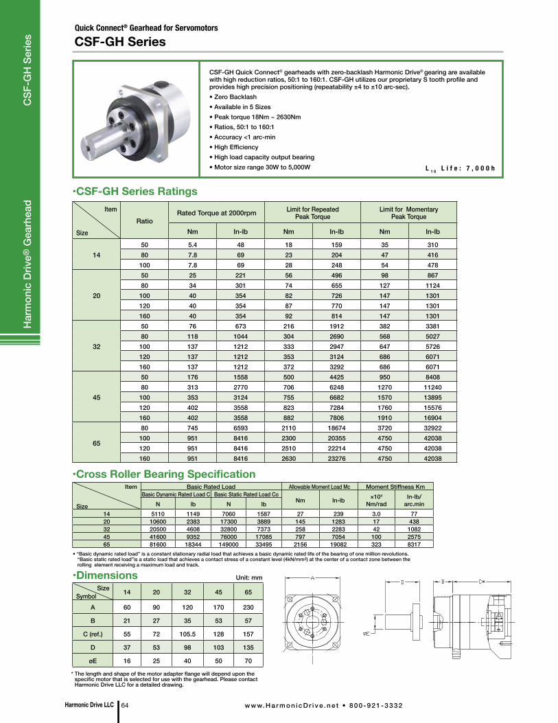
Quick Connect® Gearhead for Servomotors
CSF-GH Series
CSF-GH Quick Connect® gearheads with zero-backlash Harmonic Drive® gearing are available with high reduction ratios, 50:1 to 160:1. CSF-GH utilizes our proprietary S tooth profile and provides high precision positioning (repeatability ±4 to ±10 arc-sec). • Zero Backlash• Available in 5 Sizes• Peak torque 18Nm ~ 2630Nm• Ratios, 50:1 to 160:1• Accuracy <1 arc-min• High Efficiency• High load capacity output bearing• Motor size range 30W to 5,000W L 1 0 L i f e : 7 , 0 0 0 h
SizeSymbol 14 20 32 45 65
A 60 90 120 170 230
B 21 27 35 53 57
C (ref.) 55 72 105.5 128 157
D 37 53 98 103 135
øE 16 25 40 50 70
Unit: mm•Dimensions
• “Basic dynamic rated load” is a constant stationary radial load that achieves a basic dynamic rated life of the bearing of one million revolutions. “Basic static rated load”is a static load that achieves a contact stress of a constant level (4kN/mm2) at the center of a contact zone between the rolling element receiving a maximum load and track.
•Cross Roller Bearing Specification
Item
SizeRatio
Rated Torque at 2000rpm Limit for Repeated Peak Torque
Limit for Momentary Peak Torque
Nm In-lb Nm In-lb Nm In-lb
1450 5.4 48 18 159 35 31080 7.8 69 23 204 47 416100 7.8 69 28 248 54 478
20
50 25 221 56 496 98 86780 34 301 74 655 127 1124100 40 354 82 726 147 1301120 40 354 87 770 147 1301160 40 354 92 814 147 1301
32
50 76 673 216 1912 382 338180 118 1044 304 2690 568 5027100 137 1212 333 2947 647 5726120 137 1212 353 3124 686 6071160 137 1212 372 3292 686 6071
45
50 176 1558 500 4425 950 840880 313 2770 706 6248 1270 11240100 353 3124 755 6682 1570 13895120 402 3558 823 7284 1760 15576160 402 3558 882 7806 1910 16904
65
80 745 6593 2110 18674 3720 32922100 951 8416 2300 20355 4750 42038120 951 8416 2510 22214 4750 42038160 951 8416 2630 23276 4750 42038
•CSF-GH Series Ratings
* The length and shape of the motor adapter flange will depend upon the specific motor that is selected for use with the gearhead. Please contact Harmonic Drive LLC for a detailed drawing.
Item
Size
Basic Rated Load Allowable Moment Load Mc Moment Stiffness KmBasic Dynamic Rated Load C Basic Static Rated Load Co
Nm In-lb ×104
Nm/radIn-lb/
arc.minN lb N lb14 5110 1149 7060 1587 27 239 3.0 7720 10600 2383 17300 3889 145 1283 17 43832 20500 4608 32800 7373 258 2283 42 108245 41600 9352 76000 17085 797 7054 100 257565 81600 18344 149000 33495 2156 19082 323 8317
Harmonic Drive LLC 64 w w w. H a r m o n i c D r i v e . n e t • 8 0 0 - 9 2 1 - 3 3 3 2
Har
mon
ic D
rive®
Gea
rhea
d C
SF-G
H S
erie
s
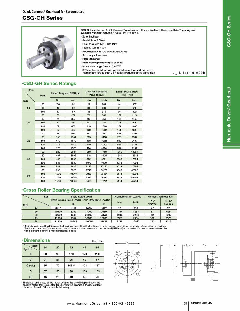
Quick Connect® Gearhead for Servomotors
CSG-GH Series
CSG-GH high-torque Quick Connect® gearheads with zero backlash Harmonic Drive® gearing are available with high reduction ratios, 50:1 to 160:1. • Zero Backlash• Available in 5 Sizes• Peak torque 23Nm ~ 3419Nm• Ratios, 50:1 to 160:1• Repeatability as low as 4 arc-seconds• Accuracy <1 arc-min• High Efficiency• High load capacity output bearing• Motor size range 30W to 5,000W• 30% higher rated torque, repeated peak torque & maximum momentary torque than CSF series products of the same size L 1 0 L i f e : 1 0 , 0 0 0 h
Item
Size
Basic Rated Load Allowable Moment Load Mc Moment Stiffness KmBasic Dynamic Rated Load C Basic Static Rated Load Co
Nm In-lb ×104
Nm/radIn-lb/
arc.minN lb N lb14 5110 1149 7060 1587 27 239 3.0 7720 10600 2383 17300 3889 145 1283 17 43832 20500 4608 32800 7373 258 2283 42 108245 41600 9352 76000 17085 797 7054 100 257565 81600 18344 149000 33495 2156 19082 323 8317
• “Basic dynamic rated load” is a constant stationary radial load that achieves a basic dynamic rated life of the bearing of one million revolutions. “Basic static rated load”is a static load that achieves a contact stress of a constant level (4kN/mm2) at the center of a contact zone between the rolling element receiving a maximum load and track.
•Cross Roller Bearing Specification
•CSG-GH Series RatingsItem
Size
RatioRated Torque at 2000rpm Limit for Repeated
Peak TorqueLimit for Momentary
Peak Torque
Nm In-lb Nm In-lb Nm In-lb
1450 7.0 62 23 204 46 40780 10 89 30 266 61 540
100 10 89 36 319 70 620
20
50 33 292 73 646 127 112480 44 389 96 850 165 1460
100 52 460 107 947 191 1690120 52 460 113 1000 191 1690160 52 460 120 1062 191 1690
32
50 99 876 281 2487 497 439980 153 1354 395 3496 738 6532
100 178 1575 433 3832 812 7187120 178 1575 459 4062 812 7187160 178 1575 484 4284 812 7187
45
50 229 2027 650 5753 1235 1093180 407 3602 918 8125 1651 14613
100 459 4062 982 8691 2033 17994120 523 4629 1070 9470 2033 17994160 523 4629 1147 10152 2033 17994
65
80 969 8576 2743 24278 4836 42802100 1236 10940 2990 26464 5174 45794120 1236 10940 3263 28880 5174 45794160 1236 10940 3419 30261 5174 45794
SizeSymbol 14 20 32 45 65
A 60 90 120 170 230
B 21 27 35 53 57
C (ref.) 55 72 105.5 128 157
D 37 53 98 103 135
øE 16 25 40 50 70
Unit: mm•Dimensions
* The length and shape of the motor adapter flange will depend upon the specific motor that is selected for use with the gearhead. Please contact Harmonic Drive LLC for a detailed drawing.
Harmonic Drive LLCw w w. H a r m o n i c D r i v e . n e t • 8 0 0 - 9 2 1 - 3 3 3 2 65
Har
mon
ic D
rive®
Gea
rhea
d C
SG-G
H S
erie
s
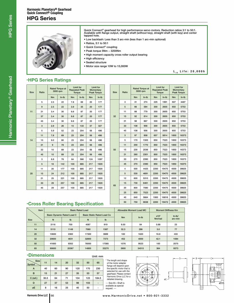
•Dimensions
Harmonic Drive LLC 66 w w w. H a r m o n i c D r i v e . n e t • 8 0 0 - 9 2 1 - 3 3 3 2
Quick Connect® gearhead for high performance servo motors. Reduction ratios 3:1 to 50:1. Available with flange output, straight shaft (without key), straight shaft (with key) and center tapped hole.• Low backlash: Less than 3 arc-min (less than 1 arc-min optional)• Ratios, 3:1 to 50:1• Quick Connect® coupling • Peak torque 5Nm ~ 3200Nm• High moment capacity cross roller output bearing• High efficiency• Sealed structure• Motor size range 10W to 15,000W
Harmonic Planetary® GearheadQuick Connect® Coupling
L 1 0 L i f e : 2 0 , 0 0 0 h
HPG Series
•HPG Series Ratings
Size Ratio Rated Torque at
3000 rpm
Limit for Repeated Peak
Torque
Limit for Momentary Peak Torque
Nm In-lb Nm In-lb Nm In-lb
11
5 2.5 22 7.8 69 20 177
9 2.5 22 3.9 35 20 177
21 3.4 30 9.8 87 20 177
37 3.4 30 9.8 87 20 177
45 3.4 30 9.8 87 20 177
14
3 2.9 26 15 133 37 327
5 5.9 52 23 204 56 496
11 7.8 69 23 204 56 496
15 9.0 80 23 204 56 496
21 9 78 23 204 56 496
33 10 89 23 204 56 496
45 10 89 23 204 56 496
20
3 8.8 78 64 566 124 1097
5 16 142 100 885 217 1920
11 20 177 100 885 217 1920
15 24 212 100 885 217 1920
21 25 221 100 885 217 1920
33 29 257 100 885 217 1920
45 29 257 100 885 217 1920
Size Ratio Rated Torque at
3000 rpm
Limit for Repeated Peak
Torque
Limit for Momentary Peak Torque
Nm In-lb Nm In-lb Nm In-lb
32
3 31 274 225 1991 507 4487
5 66 584 300 2655 650 5753
11 88 779 300 2655 650 5753
15 92 814 300 2655 650 5753
21 98 867 300 2655 650 5753
33 108 956 300 2655 650 5753
45 108 956 300 2655 650 5753
50
3 97 858 657 5814 1850 16373
5 170 1505 850 7523 1850 16373
11 200 1770 850 7523 1850 16373
15 230 2036 850 7523 1850 16373
21 260 2301 850 7523 1850 16373
33 270 2390 850 7523 1850 16373
45 270 2390 850 7523 1850 16373
65
4 500 4425 2200 19470 4500 39825
5 530 4691 2200 19470 4500 39825
12 600 5310 2200 19470 4500 39825
15 730 6461 2200 19470 4500 39825
20 800 7080 2200 19470 4500 39825
25 850 7523 2200 19470 4500 39825
40 640 5664 1900 16816 4500 39825
50 750 6638 2200 19472 4500 39825
Item
Size
Basic Rated Load Allowable Moment Load MC Moment Stiffness Km
Basic Dynamic Rated Load C Basic Static Rated Load CoNm In-lb x104
Nm/radIn-lb/
arc-min N lb N lb
11 3116 700 4087 919 9.50 84 0.88 23
14 5110 1149 7060 1587 32.3 286 3.0 77
20 10600 2383 17300 3889 183 1620 16.8 433
32 20600 4631 32800 7373 452 4000 42.1 1084
50 41600 9352 76000 17085 1076 9523 100 2575
65 90600 20367 14800 33270 3900 34515 364 9373
•Cross Roller Bearing Specification
SizeSymbol
11 14 20 32 50 65
A 40 60 90 120 170 230
B 15 21 27 35 53 57
C (ref.) 30.5 64 71 104 123 184.5
D 27 37 53 98 103 -
øE 8 16 25 40 50 -
* The length and shape of the motor adapter flange will depend upon the specific motor that is selected for use with the gearhead. Please contact Harmonic Drive LLC for a detailed drawing.
--- Size 65—Shaft is available as special request. ---
Unit: mm
Har
mon
ic P
lane
tary
® G
earh
ead
HPG
Ser
ies
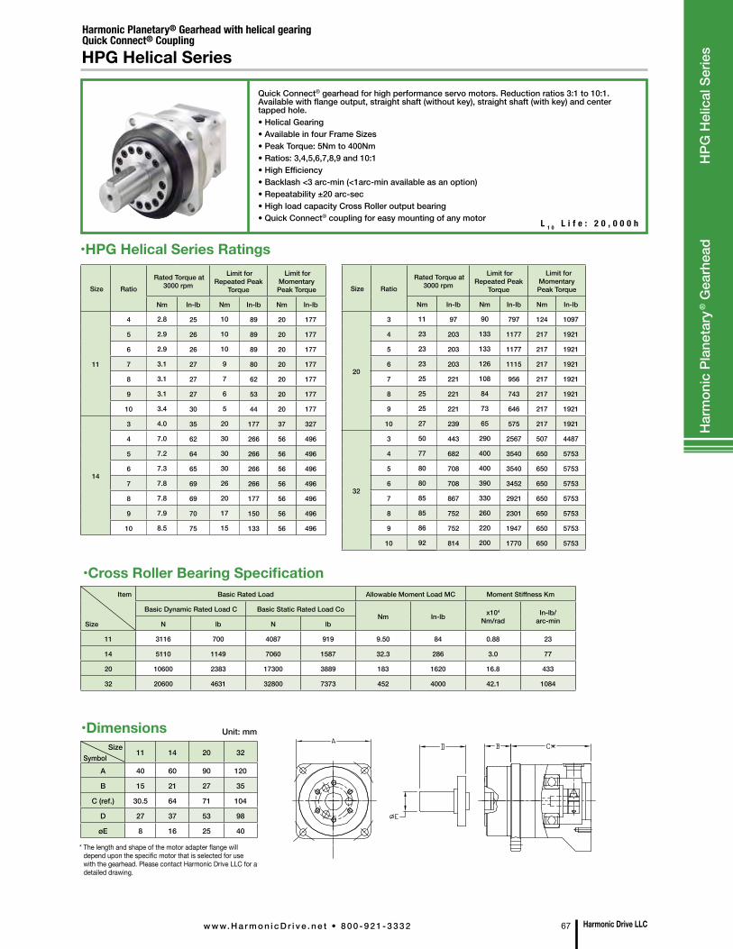
•Dimensions
Harmonic Drive LLCw w w. H a r m o n i c D r i v e . n e t • 8 0 0 - 9 2 1 - 3 3 3 2 67
Quick Connect® gearhead for high performance servo motors. Reduction ratios 3:1 to 10:1. Available with flange output, straight shaft (without key), straight shaft (with key) and center tapped hole.• Helical Gearing• Available in four Frame Sizes• Peak Torque: 5Nm to 400Nm• Ratios: 3,4,5,6,7,8,9 and 10:1• High Efficiency• Backlash <3 arc-min (<1arc-min available as an option)• Repeatability ±20 arc-sec• High load capacity Cross Roller output bearing• Quick Connect® coupling for easy mounting of any motor
Harmonic Planetary® Gearhead with helical gearingQuick Connect® Coupling
L 1 0 L i f e : 2 0 , 0 0 0 h
HPG Helical Series
•HPG Helical Series Ratings
Size Ratio Rated Torque at
3000 rpm
Limit for Repeated Peak
Torque
Limit for Momentary Peak Torque
Nm In-lb Nm In-lb Nm In-lb
11
4 2.8 25 10 89 20 177
5 2.9 26 10 89 20 177
6 2.9 26 10 89 20 177
7 3.1 27 9 80 20 177
8 3.1 27 7 62 20 177
9 3.1 27 6 53 20 177
10 3.4 30 5 44 20 177
14
3 4.0 35 20 177 37 327
4 7.0 62 30 266 56 496
5 7.2 64 30 266 56 496
6 7.3 65 30 266 56 496
7 7.8 69 26 266 56 496
8 7.8 69 20 177 56 496
9 7.9 70 17 150 56 496
10 8.5 75 15 133 56 496
Size Ratio Rated Torque at
3000 rpm
Limit for Repeated Peak
Torque
Limit for Momentary Peak Torque
Nm In-lb Nm In-lb Nm In-lb
20
3 11 97 90 797 124 1097
4 23 203 133 1177 217 1921
5 23 203 133 1177 217 1921
6 23 203 126 1115 217 1921
7 25 221 108 956 217 1921
8 25 221 84 743 217 1921
9 25 221 73 646 217 1921
10 27 239 65 575 217 1921
32
3 50 443 290 2567 507 4487
4 77 682 400 3540 650 5753
5 80 708 400 3540 650 5753
6 80 708 390 3452 650 5753
7 85 867 330 2921 650 5753
8 85 752 260 2301 650 5753
9 86 752 220 1947 650 5753
10 92 814 200 1770 650 5753
Item
Size
Basic Rated Load Allowable Moment Load MC Moment Stiffness Km
Basic Dynamic Rated Load C Basic Static Rated Load CoNm In-lb x104
Nm/radIn-lb/
arc-minN lb N lb
11 3116 700 4087 919 9.50 84 0.88 23
14 5110 1149 7060 1587 32.3 286 3.0 77
20 10600 2383 17300 3889 183 1620 16.8 433
32 20600 4631 32800 7373 452 4000 42.1 1084
•Cross Roller Bearing Specification
SizeSymbol
11 14 20 32
A 40 60 90 120
B 15 21 27 35
C (ref.) 30.5 64 71 104
D 27 37 53 98
øE 8 16 25 40
* The length and shape of the motor adapter flange will depend upon the specific motor that is selected for use with the gearhead. Please contact Harmonic Drive LLC for a detailed drawing.
Unit: mm
Har
mon
ic P
lane
tary
® G
earh
ead
HPG
Hel
ical
Ser
ies
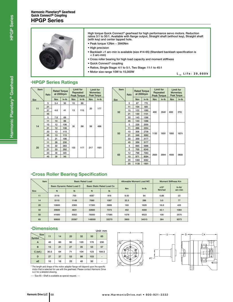
Har
mon
ic P
lane
tary
® G
earh
ead
H
PGP
Serie
s
High torque Quick Connect® gearhead for high performance servo motors. Reduction ratios 3:1 to 50:1. Available with flange output, Straight shaft (without key), Straight shaft (with key) and center tapped hole.• Peak torque 12Nm ~ 3940Nm • High precision • Backlash <1 arc-min is available (size #14-65) (Standard backlash specification is < 3 arc-min)• Cross roller bearing for high load capacity and moment stiffness• Quick Connect® coupling • Ratios, Single Stage: 4:1 to 5:1, Two Stage: 11:1 to 45:1• Motor size range 10W to 15,000W
Harmonic Planetary® GearheadQuick Connect® Coupling
L 1 0 L i f e : 2 0 , 0 0 0 h
HPGP Series
•HPGP Series Ratings
Item
Size
Basic Rated Load Allowable Moment Load MC Moment Stiffness Km
Basic Dynamic Rated Load C Basic Static Rated Load CoNm In-lb x104
Nm/radIn-lb/
arc-minN lb N lb
11 3116 700 4087 919 9.50 84 0.88 23
14 5110 1149 7060 1587 32.3 286 3.0 77
20 10600 2383 17300 3889 183 1620 16.8 433
32 20600 4631 32800 7373 452 4000 42.1 1084
50 41600 9352 76000 17085 1076 9523 100 2575
65 90600 20367 148000 33270 3900 34515 364 9373
•Cross Roller Bearing Specification
SizeSymbol
11 14 20 32 50 65
A 40 60 90 120 170 230
B 15 21 27 35 53 57
C (ref.) 30.5 64 71 104 123 184.5
D 27 37 53 98 103 -
øE 10 16 25 40 50 -
* The length and shape of the motor adapter flange will depend upon the specific motor that is selected for use with the gearhead. Please contact Harmonic Drive LLC for a detailed drawing.
---- Size 65—Shaft is available as special request. ---
Unit: mm
Item
Size
RatioRated Torque at 2000rpm
Limit for Repeated
Peak Torque
Limit for Momentary Peak Torque
Nm In-lb Nm In-lb Nm In-lb
32
5 87 770
400 3540 650 5753
11 104 92015 122 108021 130 115133 143 126645 143 1266
50
5 226 2000
1130 10001 1850 16374
11 266 235415 306 270821 346 306233 359 317745 359 3177
65
4 665 5886
2920 25844 4500 39828
5 705 624012 798 706315 971 859420 1060 938225 1130 10001
Item
Size
RatioRated Torque at 2000rpm
Limit for Repeated
Peak Torque
Limit for Momentary Peak Torque
Nm In-lb Nm In-lb Nm In-lb
11
5 3.4 30 10 89
20 17721
4.6 41 13 1153745
14
5 7.8 69
30 266 56 496
11 10 8915 12 10621 12 10633 13 11545 13 115
20
5 21 186
133 1177 217 1921
11 26 23015 32 28321 33 29233 39 34545 39 345
•Dimensions
Harmonic Drive LLC 68 w w w. H a r m o n i c D r i v e . n e t • 8 0 0 - 9 2 1 - 3 3 3 2
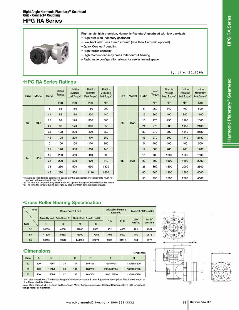
Right angle, high precision, Harmonic Planetary® gearhead with low backlash.• High precision Planetary gearhead• Low backlash: Less than 3 arc-min (less than 1 arc-min optional)• Quick Connect® coupling • High torque capacity• High moment capacity cross roller output bearing• Right angle configuration allows for use in limited space
Right Angle Harmonic Planetary® GearheadQuick Connect® CouplingHPG RA Series
•HPG RA Series Ratings
Size Model Ratio Rated Torque
Limit for Average
Load Torque*1
Limit for Repeated
Peak Torque*2
Limit for Momentary
Peak Torque*3
Nm Nm Nm Nm
32 RA3
5 66 150 150 200
11 88 170 330 440
15 92 170 300 600
21 98 170 300 650
33 108 200 330 650
45 108 200 300 650
50 RA3
5 150 150 150 200
11 170 330 330 440
15 200 450 450 600
21 200 500 630 840
33 230 500 990 1320
45 230 500 1140 1800
Size Model Ratio Rated Torque
Limit for Average
Load Torque*1
Limit for Repeated
Peak Torque*2
Limit for Momentary
Peak Torque*3
Nm Nm Nm Nm
50 RA5
5 260 340 400 500
12 260 400 880 1100
15 270 450 1200 1500
21 270 500 1150 2100
33 270 500 1140 2180
45 270 500 1140 2180
65 RA5
5 400 400 400 500
12 600 960 960 1200
15 730 1200 1200 1500
20 800 1500 1600 2000
25 850 1500 2000 2500
40 640 1300 1900 4000
50 750 1500 2200 4500
Item
Size
Basic Rated Load Allowable Moment Load MC Moment Stiffness Km
Basic Dynamic Rated Load C Basic Static Rated Load CoNm In-lb x104
Nm/radIn-lb/
arc-minN lb N lb
32 20500 4608 32800 7373 452 4000 42.1 1084
50 41600 9352 76000 17085 1076 9523 100 2575
65 90600 20367 148000 33270 3900 34515 364 9373
•Cross Roller Bearing Specification
Size A øB C D E* F G
32 120 115h7 35 107 140/175 175/197/217 130/180/220
50 170 165h8 53 144 168/200 209/234/254 130/180/220
65 230 220h8 57 226 168/200 291/316/336 130/180/220
* Left side description: The limited length of the Motor shaft is 81mm. Right side description: The limited length of the Motor shaft is 116mm.
Note: Dimensions F & G depend on the chosen Motor flange square size. Contact Harmonic Drive LLC for special flange motor combination.
*1: Average load torque calculated based on the application motion profile must not exceed values shown in the table.
*2: The limit for torque during start and stop cycles. Always operate below this value.*3: The limit for torque during emergency stops or from external shock loads.
Unit: mm
L 1 0 L i f e : 2 0 , 0 0 0 h
•Dimensions
Harmonic Drive LLCw w w. H a r m o n i c D r i v e . n e t • 8 0 0 - 9 2 1 - 3 3 3 2 69
Har
mon
ic P
lane
tary
® G
earh
ead
H
PG R
A Se
ries
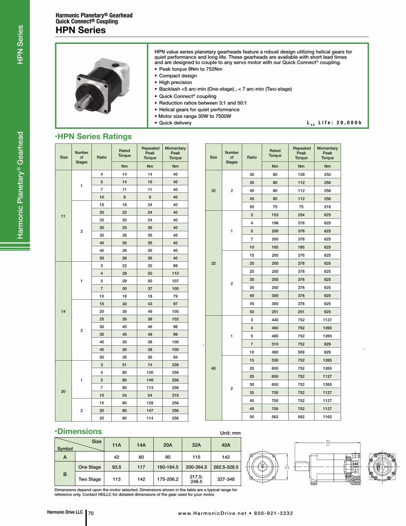
Harmonic Drive LLC 70 w w w. H a r m o n i c D r i v e . n e t • 8 0 0 - 9 2 1 - 3 3 3 2
Har
mon
ic P
lane
tary
® G
earh
ead
H
PN S
erie
s
L 5 0 L i f e : 2 0 , 0 0 0 h
HPN value series planetary gearheads feature a robust design utilizing helical gears for quiet performance and long life. These gearheads are available with short lead times and are designed to couple to any servo motor with our Quick Connect® coupling.• Peak torque 9Nm to 752Nm • Compact design • High precision • Backlash <5 arc-min (One-stage) , < 7 arc-min (Two-stage) • Quick Connect® coupling • Reduction ratios between 3:1 and 50:1 • Helical gears for quiet performance• Motor size range 30W to 7500W • Quick delivery
Harmonic Planetary® GearheadQuick Connect® CouplingHPN Series
•HPN Series Ratings
Size Number
of Stages
Ratio Rated Torque
Repeated Peak
Torque
Momentary Peak
Torque
Nm Nm Nm
11
1
4 14 14 40
5 14 16 40
7 11 11 40
10 9 9 40
2
15 18 24 40
20 22 24 40
25 20 24 40
30 25 26 40
35 26 26 40
40 26 26 40
45 26 26 40
50 26 26 40
14
1
3 22 25 89
4 28 50 110
5 29 50 107
7 30 37 100
10 18 18 79
2
15 30 43 97
20 30 49 100
25 30 38 102
30 40 48 98
35 40 49 99
40 30 38 100
45 30 38 100
50 26 26 94
20
1
3 51 74 226
4 80 130 256
5 80 149 256
7 80 113 256
10 54 54 216
2
15 80 129 256
20 80 147 256
25 80 114 256
SizeNumber
of Stages
Ratio Rated Torque
Repeated Peak
Torque
Momentary Peak
Torque
Nm Nm Nm
20 2
30 80 139 250
35 80 112 256
40 80 112 256
45 80 112 256
50 75 75 216
32
1
3 153 254 625
4 198 376 625
5 200 376 625
7 200 376 625
10 185 185 625
2
15 200 376 625
20 200 376 625
25 200 376 625
30 250 376 625
35 250 376 625
40 300 376 625
45 300 376 625
50 251 251 625
40
1
3 440 752 1137
4 460 752 1265
5 480 752 1265
7 510 752 829
10 480 509 829
2
15 530 752 1265
20 600 752 1265
25 650 752 1127
30 650 752 1265
35 700 752 1127
40 700 752 1127
45 700 752 1127
50 562 562 1162
•DimensionsSize
Symbol11A 14A 20A 32A 40A
A 42 60 90 115 142
BOne Stage 93.5 117 160-184.5 200-264.5 282.5-328.5
Two Stage 113 142 175-206.2 217.5-246.5 327-348
Unit: mm
Dimensions depend upon the motor selected. Dimensions shown in the table are a typical range for reference only. Contact HDLLC for detailed dimensions of the gear used for your motor.
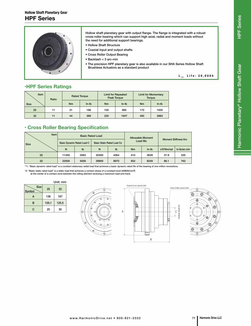
Size Symbol
25 32
A 136 167
B 105.1 125.5
C 25 30
Unit: mm
Item
Size
RatioRated Torque Limit for Repeated
Peak TorqueLimit for Momentary
Torque
Nm In-lb Nm In-lb Nm In-lb
25 11 21 186 100 885 170 1505
32 11 44 389 220 1947 450 3983
•HPF Series Ratings
• Cross Roller Bearing SpecificationItem
Size
Basic Rated Load Allowable Moment Load Mc Moment Stiffness Km
Basic Dynamic Rated Load C Basic Static Rated Load Co
N lb N lb Nm In-lb x104Nm/rad In-lb/arc.min
25 11400 2563 20300 4564 410 3629 37.9 335
32 22500 5058 39900 8970 932 8249 86.1 762
Hollow Shaft Planetary GearHPF Series
Hollow shaft planetary gear with output flange. The flange is integrated with a robust cross-roller bearing which can support high axial, radial and moment loads without the need for additional support bearings.• Hollow Shaft Structure• Coaxial input and output shafts• Cross Roller Output Bearing• Backlash < 3 arc-min • The precision HPF planetary gear is also available in our SHA Series Hollow Shaft Brushless Actuators as a standard product
**1: “Basic dynamic rated load” is a constant stationary radial load that achieves a basic dynamic rated life of the bearing of one million revolutions.
*2: “Basic static rated load” is a static load that achieves a contact stress of a constant level (408kN/mm2) at the center of a contact zone between the rolling element receiving a maximum load and track.
A
B
C
Item
Output (Low-speed side)Input (High-speed side)
Hol
low
Sha
ft ID
L 1 0 L i f e : 2 0 , 0 0 0 h
Harmonic Drive LLCw w w. H a r m o n i c D r i v e . n e t • 8 0 0 - 9 2 1 - 3 3 3 2 71
Har
mon
ic P
lane
tary
® H
ollo
w S
haft
Gea
r
HPF
Ser
ies
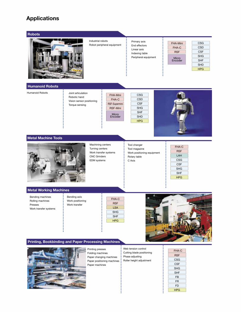
Industrial robotsRobot peripheral equipment
Primary axisEnd effectorsLinear axisIndexing tablePeripheral equipment
Joint articulationRobotic hand Vision sensor positioningTorque sensing
Tool changer Tool magazineWork positioning equipmentRotary tableC Axis
Machining centersTurning centersWork transfer systemsCNC GrindersEDM systems
Bending machinesRolling machinesPressesWork transfer systems
Bending axisWork positioningWork transfer
Printing pressesFolding machinesPaper changing machinesPaper positioning machinesPaper machines
Web tension controlCutting blade positioningPhase adjustingRoller height adjustment
Humanoid Robots
Robots
Humanoid Robots
Metal Machine Tools
Metal Working Machines
Printing, Bookbinding and Paper Processing Machines
Applications
CSGCSDCSFSHGSHFSHDHPG
CSGCSDCSFSHGSHFSHDHPG
FHA-Mini FHA-C
RSF
Micro Encoder
FHA-CRSFLAH CSGCSFSHGSHFHPG
FHA-CRSFLSA SHGSHFHPG
RSFCSGCSFSHGSHFFBFRFD
HPG
FHA-C
FHA-Mini FHA-C
RSF-SuperminiRSF-Mini
Micro Encoder
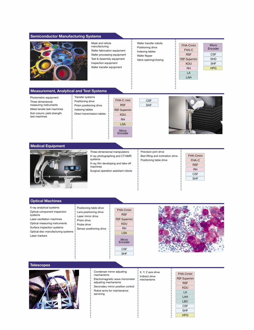
X-ray analytical systemsOptical component inspection systemsLaser oscillation machinesOptical measuring instrumentsSurface inspection systemsOptical disc manufacturing systemsLaser markers
Three-dimensional manipulatorsX-ray photographing and CT-NMR systemsX-ray film developing and take-off machinesSurgical operation assistant robots
X, Y, Z axis driveIndirect drive mechanisms
Condenser mirror adjusting mechanismsElectromagnetic wave micrometer adjusting mechanismsSecondary mirror position controlRobot arms for maintenance servicing
Positioning table driveLens positioning driveLaser mirror drivePrism driveProbe driveSensor positioning drive
Precision joint driveBed lifting and inclination drivePositioning table drive
Photometric equipmentThree-dimensional measuring instrumentsMetal tensile test machinesSoil-column yield strength test machines
Transfer systemsPositioning drivePrism positioning driveIndexing tablesDirect transmission tables
Mask and reticle manufacturingWafer fabrication equipmentWafer processing equipmentTest & Assembly equipmentInspection equipmentWafer transfer equipment
Wafer transfer robotsPositioning driveIndexing tablesWafer flipperValve opening/closing
Telescopes
Optical Machines
Medical Equipment
Semiconductor Manufacturing Systems
FHA-CminiFHA-C
RSF RSF-Supermini
KDURHLA
LAH
Micro Encoder
CSFSHDSHFHPG
FHA-C miniRSF
RSF-SuperminiKDURHLSA
Micro Encoder
FHA-CminiFHA-C
RSFRHCSFSHF
FHA-CminiRSF
RSF-SuperminiKDURHLSA
Micro Encoder
CSFSHF
FHA-CminiRSF-Supermini
RSFKDULA
LAHLBC CSFSHFHPG
CSFSHF
Measurement, Analytical and Test Systems
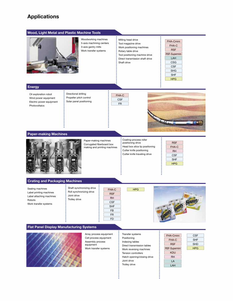
Wood, Light Metal and Plastic Machine Tools
FHA-CminiFHA-C
RSFRSF-Supermini
LAHCSGCSFSHGSHFHPG
FHA-CCSFFR
Oil exploration robotWind power equipmentElectric power equipmentPhotovoltaics
RSFFHA-C
RH CSFSHFHPG
Sealing machinesLabel printing machinesLabel attaching machinesRobotsWork transfer systems
Shaft synchronizing driveRoll synchronizing driveJoint driveTrolley drive
FHA-CRSF RHCSFSHFFBFRFD
Transfer systemsPositioningIndexing tablesDirect transmission tablesWork reversing machinesTension controllersHatch opening/closing driveJoint driveTrolley drive
FHA-CminiFHA-C
RSFRSF-Supermini
KDURH LA
LAH
Paper-making Machines
Energy
Crating and Packaging Machines
Flat Panel Display Manufacturing Systems
CSFSHFSHD HPG
Woodworking machines5-axis machining centers3-axis gantry millsWork transfer systems
Paper-making machinesCorrugated fiberboard box making and printing machines
Directional drillingPropeller pitch controlSolar panel positioning
Coating-process roller positioning driveHead box slice lip positioningCutter knife positioningCutter knife traveling drive
Array process equipmentCell process equipmentAssembly process equipmentWork transfer systems
Milling head driveTool magazine driveWork positioning machinesRotary table driveTool positioning machine driveDirect transmission shaft driveShaft drive
HPG
Applications
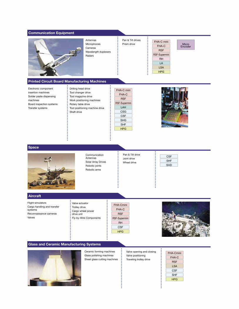
Drilling head driveTool changer driveTool magazine driveWork positioning machinesRotary table driveTool positioning machine driveShaft drive
Flight simulatorsCargo handling and transfer systemsReconnaissance camerasValves
AntennasMicrophonesCamerasWavelength duplexersRadars
Pan & Tilt drivesPrism drive
Communication Equipment
FHA-C miniFHA-C
RSFRSF-Supermini
RHLA
LSA HPG
Electronic componentinsertion machinesSolder paste dispensingmachinesBoard inspection systemsTransfer systems
Printed Circuit Board Manufacturing Machines
FHA-C miniFHA-C
RSFRSF-Supermini
LAH CSGCSFSHGSHFHPG
Communication AntennasSolar Array DrivesRobotic jointsRobotic arms
Pan & Tilt driveJoint driveWheel drive
Valve actuatorTrolley driveCargo wheel power drive unitFly-by-Wire Components
CSFSHFSHD
Space
Aircraft
FHA-CminiFHA-C
RSFRSF-Supermini
RH CSFHPG
Ceramic forming machinesGlass polishing machinesSheet glass cutting machines
Valve opening and closingValve positioningTraveling trolley drive
FHA-CminiFHA-C
RSFLSA CSFSHFHPG
Glass and Ceramic Manufacturing Systems
Micro Encoder
Rev 20190417
Group CompaniesHarmonic Drive Systems, Inc.6-25-3 Minami-Ohi, Shinagawa-kuTokyo 141-0013, Japan
Harmonic Drive AGHoenbergstrasse, 14, D-6555Limburg/Lahn Germany
Harmonic Drive LLCUS Headquarters247 Lynnfield Street Peabody, MA 01960
New York Sales Office100 Motor ParkwaySuite 116Hauppauge, NY 11788
California Sales Office333 W. San Carlos Street Suite 1070San Jose, CA 95110
Chicago Sales Office137 N. Oak Park Ave., Suite 410Oak Park, IL 60301
T: 800.921.3332 T: 978.532.1800 F: 978.532.9406
www.HarmonicDrive.net
Harmonic Drive, Harmonic Planetary, Infinit-Indexer and Quick Connect are registered trademarks of Harmonic Drive LLC.
All efforts have been made to ensure that the information in this catalog is complete and accurate. However, Harmonic Drive LLC is not liable for any errors, omissions or inaccuracies in the reported data. Harmonic Drive LLC reserves the right to change the product specifications, for any reason, without prior notice. For complete details please refer to our current Terms and Conditions posted on our website.