precision allocation method of large-scale cnc hobbing
TRANSCRIPT

Precision Allocation Method of Large-Scale CNCHobbing Machine Based On Precision-CostComprehensive OptimizationZongyan Hu ( [email protected] )
Chongqing UniversityShilong Wang ( [email protected] )
Chongqing UniversityChi Ma
Chongqing University
Research Article
Keywords: Gear hobbing machine, Comprehensive error model, Precision allocation, Precision-cost model,Multi-object optimization
Posted Date: November 19th, 2021
DOI: https://doi.org/10.21203/rs.3.rs-1069776/v1
License: This work is licensed under a Creative Commons Attribution 4.0 International License. Read Full License
1
Precision allocation method of large-scale CNC hobbing machine
based on precision-cost comprehensive optimization
Zongyan Hu
The State Key Laboratory of Mechanical Transmission, Chongqing University, Chongqing
400030, China, e-mail: [email protected]
Shilong Wang* (Corresponding author)
The State Key Laboratory of Mechanical Transmission, Chongqing University, Chongqing
400030, China, e-mail: [email protected]
Chi Ma
The State Key Laboratory of Mechanical Transmission, Chongqing University, Chongqing
400030, China, e-mail: [email protected]
Abstract: In modern machine tool design, precision is an important index to characterize machine
tool performance. and precision allocation has become a key task. Since middle 20th century, the
precision allocation method using optimization technology to balance manufacturing cost and
quality has gradually developed. But most methods mainly take the cost minimization as the goal
to optimize the precision allocation. As the precision and manufacturing cost are a pair of factors to
be comprehensively considered, balance between them is needed to meet different design
requirements. This paper proposes a comprehensive optimization method to trade-off between
precision and cost. A multi-object precision allocation optimization model aiming at minimizing
fuzzy manufacturing cost and comprehensive precision of machine tool is constructed. A multi-
object optimization algorithm to solve the model is designed, combining the multi-objective grey
wolf optimization algorithm with multi-objective decision analysis method TOPSIS. A case study
based on a large-scale hobbing machine shows that the comprehensive optimization of
manufacturing cost and machining precision is realized by using the proposed multi-object precision
allocation optimization method.
Keywords: Gear hobbing machine; Comprehensive error model; Precision allocation; Precision-
cost model; Multi-object optimization
Declarations
The authors declare that they have no known competing financial interests or personal relationships
that could have appeared to influence the work reported in this paper.
Funding
This work was supported by the Key Project of National Natural Science Foundation of China
(Grant No.51635003).
Authors' contributions
Zongyan Hu contributed to the conception of the study and wrote the manuscript;
Shilong Wang contributed to the conception of the study, funding acquisition and supervision;
Chi Ma contributed to analysis and manuscript review.
1. Introduction
Precision is an important index to characterize machine tool performance. The overall machine tool precision is determined by moving parts precision. Different parts effects the precision differently. Precision distribution is to optimize the precision design of main parts on the basis of meeting overall precision design requirements. Precision allocation has become a key task in modern machine tool design.
Early designers generally use trial-and-error method to allocate precision according to experimental data, professional knowledge or expert experience, or use some simple principles such as principle of similarity, equal tolerance, equal influence and equal precision [1]. These methods

2
mainly aim to meet the design precision of machine tools. Manufacturing cost impacts are rarely considered when allocating precision. However, the manufacturing cost is closely related to machine tool precision. Improving precision design requirements may increase the manufacturing cost. Excessive improving precision pursuit will lead to unnecessary cost increase. A good machine tool design needs to find the best balance between them.
Since the middle of the 20th century, the precision allocation method using optimization technology to balance manufacturing cost and quality has gradually developed[2]. At present, the main method is to transform the precision allocation into an optimization problem, aiming at minimizing the manufacturing cost with meeting precision design as the constraint condition, and establish a precision-cost model to get the optimal precision allocation. In the production process and actual design, the manufacturing cost is related to many factors, so it is difficult to accurately estimate the manufacturing cost with a certain precision, and it is impossible to establish a real cost function. Therefore, a relative relationship model between precision and manufacturing cost is generally established to solve the optimal precision allocation problem. At present, the commonly used models include model of exponential, power exponential, negative square, cubic or quartic polynomial, exponential power exponential composite, linear exponential composite and so on.
Sheng Hongliang et al. put forward a value analysis method of mechanism precision allocation considering three factors including function, cost and value [3]. A cost-error model with the empirical data of typical production process was established by Dong Z et al.[4]. Feng C X et al. presented a precision allocation design method aiming at the lowest cost by using the random integer programming method [5].
Diplaris S C et al. presented a analytical cost-tolerance model by considering the size of tolerance, tolerance dimension, initial tolerance and workpiece surface etc to produces results closer to industrial practice [6]. Rao S et al. proposed a precision allocation optimization method, which can minimize the given objective function on the premise of meeting required function and constraints [7]. Krishna A G and Rao established an optimization model aiming minimizing total manufacturing cost for simultaneously manufacturing tolerances and allocating design [8]. Huang X et al. proposed a global precision allocation optimization method of machine tool component precision by combining BP neural network and genetic algorithm [9]. Kang Fang et al. optimized the error parameters using genetic algorithm and established the precision allocation model of machine tool with the goal of minimum manufacturing cost [10]. Muthu et al. considered the quality loss and manufacturing cost of each component, established a nonlinear integer model aiming at minimizing manufacturing cost [11]. Sanz-Lobera A et al. established a cost-tolerance model to establish individual relation for each tolerance by considering manufacturing resource existing variabilities of each moment[12].
Aiming at minimizing manufacturing cost and motion error, Sarina adopts multi-objective nonlinear optimization method to realize precision design optimization [13]. According to reliability theory, Yu Zhimin et al. established the reliability limit state function for machining precision to meet design requirements, and established the precision allocation method for large-scale NC machine tools [14]. According to multi-body system (MBS) theory, Xing Yuan et al. established a machining quality approximate model under comprehensive actions of machine tool geometric errors, and proposed a precision reverse design method of NC machine tools [15]. Cai L et al. established both reliability and sensitivity model for machining precision under multiple failure modes, and proposed a precision allocation method to improve machine tool machining precision reliability under multiple failure modes [16]. Cheng Q et al. developed a precise allocation method to optimize the allocation of manufacturing and assembly tolerances and to minimize the cost of controlling errors and nonconformities [17]. Guo J et al. established a state space model considering error transfers and geometric errors of each part in the assembly process, and realized the optimization of precision allocation [18]. According to the cubic transformation function of fault mode and impact analysis, Yang Z et al. proposed a comprehensive reliability allocation method by considering severity and incidence of faults. [19].
By taking sum cost of service quality loss and assembly as objective function, Y. M. Zhao et al. established a product tolerance optimization model with constraint condition of the tolerance superposition and economic machining tolerance [20]. Zhang Y et al. proposed a manufacturing easiness index that can not only evaluate manufacturing difficulty, but also indirectly reflect manufacturing cost. On the premise of meeting the quality objectives and manufacturing constraints, an optimization problem aiming at maximizing the manufacturability index is proposed[21]. Zhang Z et al. proposed a geometric error allocation method with error reliability to optimize machine tools
3
reliability and total cost [22]. Liu Peng et al. established a machine tool assembly precision allocation model based on state space model with total machining cost minimization as the objective function [23]. Cai L et al. takes machine reliability as constraint and the minimum failure possibility and cost as criterion, and puts forward an optimization method for machining precision retention based on robust design [24]. Taking the minimal cost as optimization object and machining precision reliability as constraint, Zhang Z et al. proposed a geometric error budget method[25]. Balamurugan C et al. took the time cost of product degradation and quality loss into consideration, and established a tolerance allocation optimization model to minimize total loss and cost of production. Results show that the longer planning cycle will lead to the increase of tolerance cost and quality loss[26].
Cheng Bin Bin et al. established an optimization model of assembly error distribution under actual working conditions based on the modified Jacobian spinor model[27]. In order to optimize the total cost and reliability, Zhang Z proposed a precision allocation method under the geometric and operational constraints of machine tools [28]. Aiming at maximizing the interval width of geometric error sources, Tlija M et al. presented an economic tolerance allocation method considering difficulty coefficient evaluation and Lagrange multiplier [29]. Jian abstracted the precision allocation problem into a constrained minimization problem, and presented the machine tool precision allocation method analyzing contribution [30]. He C et al. presented a statistical tolerance allocation method for mechanical products considering shape error. By using deep Q-learning with reward function considering target function requirements, consistency, cost of precision maintenance and processing, the optimal solution is obtained.[30]. Based on finite element analysis, Fan J et al. established a tolerance allocation optimal method which can reduce total manufacturing cost about 11.5% considering small deformation of five axis machine tools as constraints. [32].
These researches provide effective methods for machine tool precision allocation, but these methods mainly take the comprehensive error less than or equal to the precision design requirements as the constraint condition, and take the cost minimization as the goal to optimize the precision allocation. However, in machine tool design, precision and manufacturing cost are a pair of factors to be comprehensively considered, such as the necessary precision improvement at a small cost, or the valuable manufacturing cost reduction at a tolerable precision loss. This balance between precision and cost can meet different design requirements.
In this paper, a multi-objective precision allocation optimization model aiming at minimizing fuzzy manufacturing cost and comprehensive precision of machine tools is constructed, based on the idea of comprehensive optimization of precision and cost. The precision of each component is optimized, and the comprehensive optimization of manufacturing cost and machining precision of machine tools is realized.
In the following sections, the paper structure is arranged as: First, a geometric error model of a typical large-scale CNC hobbing machine (CNC-LGHM) is presented based on the MBS theory in Section 2. Then a multi-objective precision allocation optimization model is established in Section 3. Based on multi-objective gray wolf algorithm and TOPSIS, a solution and decision-making method of precision allocation optimization model, is proposed in Section 4. The case discussion is made on a CNC-LGHM using the proposed method in Section 5. Finally, the full text is summarized.
2. Geometric error model of CNC-LGHM
Key parts Geometric error modeling is the precision allocation basis. Many methods are adopted to establish comprehensive error models, such as method of matrix transformation [33], error matrix [34], rigid body kinematics [35], D-H method [36], screw theory [37], differential transform [38] and modeling based on MBS theory[39]. Among these methods, the method which takes homogeneous coordinate transformation and MBS theory as its foundation, has advantages of less modeling assumptions, standardized process, strong formalization, good generality and easy computer automatic modeling. In recent years, it has become the preferred method of machine tool error modeling[40][41][42].
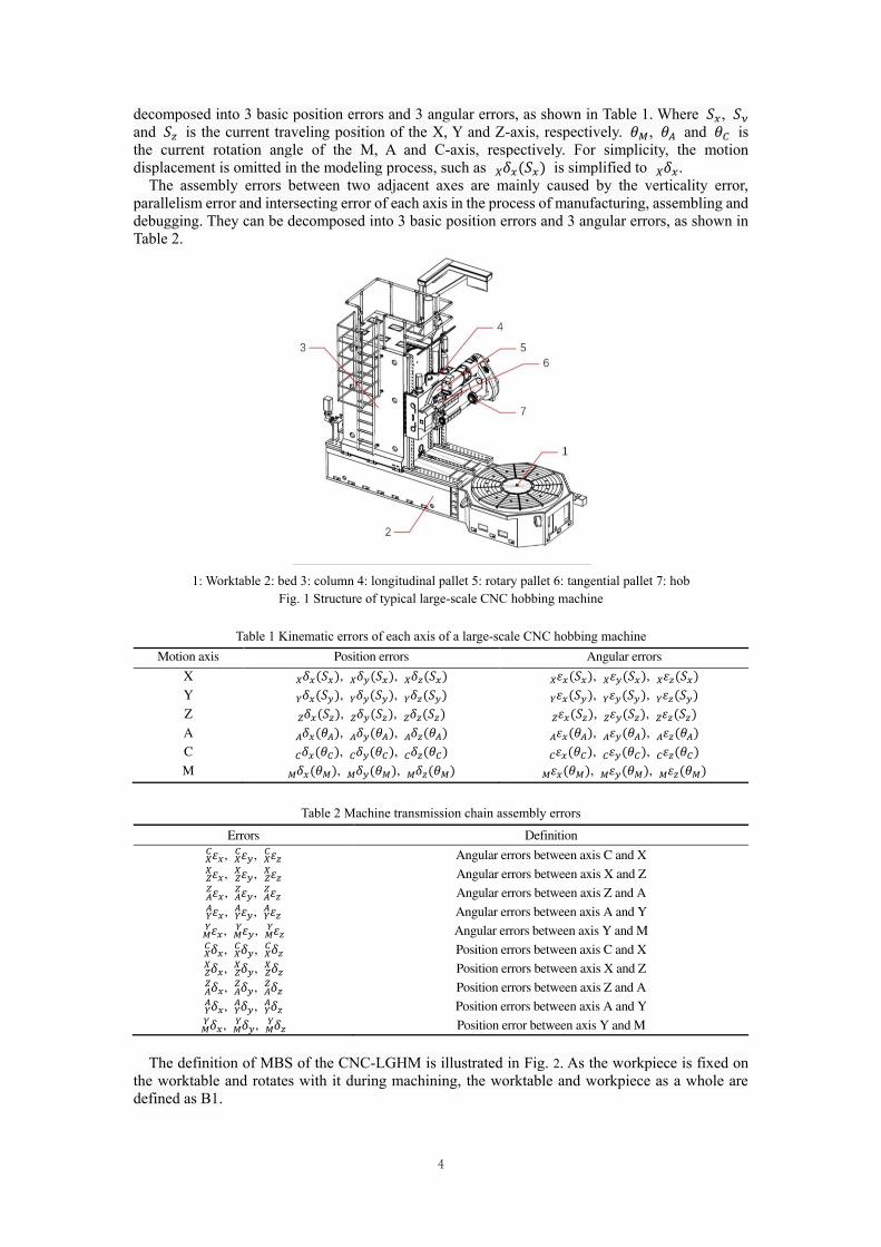
In this paper, a CNC-LGHM is taken as the object of study, and its geometric error model is presented based MBS. As shown in Fig. 1, the machine tool contains 6 moving axes during gear machining. Three of them are linear guide rails, responsible for X, Y, Z directions of motion. Three are the rotary pairs, responsible for the workpiece rotation(C), hob rotation(M), hob angle deflection(A).
The kinematic error in each axis is related to the motion displacement of the axis, and can be
4
decomposed into 3 basic position errors and 3 angular errors, as shown in Table 1. Where 𝑆𝑥, 𝑆𝑦 and 𝑆𝑧 is the current traveling position of the X, Y and Z-axis, respectively. 𝜃𝑀, 𝜃𝐴 and 𝜃𝐶 is the current rotation angle of the M, A and C-axis, respectively. For simplicity, the motion displacement is omitted in the modeling process, such as 𝛿𝑥𝑋 (𝑆𝑥) is simplified to 𝛿𝑥𝑋 .
The assembly errors between two adjacent axes are mainly caused by the verticality error, parallelism error and intersecting error of each axis in the process of manufacturing, assembling and debugging. They can be decomposed into 3 basic position errors and 3 angular errors, as shown in Table 2.
1: Worktable 2: bed 3: column 4: longitudinal pallet 5: rotary pallet 6: tangential pallet 7: hob
Fig. 1 Structure of typical large-scale CNC hobbing machine
Table 1 Kinematic errors of each axis of a large-scale CNC hobbing machine
Motion axis Position errors Angular errors
X 𝛿𝑥𝑋 (𝑆𝑥), 𝛿𝑦𝑋 (𝑆𝑥), 𝛿𝑧𝑋 (𝑆𝑥) 𝜀𝑥(𝑆𝑥)𝑋 , 𝜀𝑦𝑋 (𝑆𝑥), 𝜀𝑧𝑋 (𝑆𝑥)
Y 𝛿𝑥𝑌 (𝑆𝑦), 𝛿𝑦(𝑆𝑦)𝑌 , 𝛿𝑧𝑌 (𝑆𝑦) 𝜀𝑥𝑌 (𝑆𝑦), 𝜀𝑦𝑌 (𝑆𝑦), 𝜀𝑧(𝑆𝑦)𝑌
Z 𝛿𝑥(𝑆𝑧)𝑍 , 𝛿𝑦(𝑆𝑧)𝑍 , 𝛿𝑧𝑍 (𝑆𝑧) 𝜀𝑥𝑍 (𝑆𝑧), 𝜀𝑦(𝑆𝑧)𝑍 , 𝜀𝑧𝑍 (𝑆𝑧)
A 𝛿𝑥(𝜃𝐴)𝐴 , 𝛿𝑦𝐴 (𝜃𝐴), 𝛿𝑧(𝜃𝐴)𝐴 𝜀𝑥𝐴 (𝜃𝐴), 𝜀𝑦(𝜃𝐴)𝐴 , 𝜀𝑧𝐴 (𝜃𝐴)
C 𝛿𝑥𝐶 (𝜃𝐶), 𝛿𝑦(𝜃𝐶)𝐶 , 𝛿𝑧𝐶 (𝜃𝐶) 𝜀𝑥(𝜃𝐶)𝐶 , 𝜀𝑦𝐶 (𝜃𝐶), 𝜀𝑧(𝜃𝐶)𝐶
M 𝛿𝑥𝑀 (𝜃𝑀), 𝛿𝑦(𝜃𝑀)𝑀 , 𝛿𝑧(𝜃𝑀)𝑀 𝜀𝑥(𝜃𝑀)𝑀 , 𝜀𝑦𝑀 (𝜃𝑀), 𝜀𝑧𝑀 (𝜃𝑀)
Table 2 Machine transmission chain assembly errors
Errors Definition 𝜀𝑥𝑋𝐶 , 𝜀𝑦𝑋𝐶 , 𝜀𝑧𝑋𝐶 Angular errors between axis C and X 𝜀𝑥𝑍𝑋 , 𝜀𝑦𝑍𝑋 , 𝜀𝑧𝑍𝑋 Angular errors between axis X and Z 𝜀𝑥𝐴𝑍 , 𝜀𝑦𝐴𝑍 , 𝜀𝑧𝐴𝑍 Angular errors between axis Z and A 𝜀𝑥𝑌𝐴 , 𝜀𝑦𝑌𝐴 , 𝜀𝑧𝑌𝐴 Angular errors between axis A and Y 𝜀𝑥𝑀𝑌 , 𝜀𝑦𝑀𝑌 , 𝜀𝑧𝑀𝑌 Angular errors between axis Y and M 𝛿𝑥𝑋𝐶 , 𝛿𝑦𝑋𝐶 , 𝛿𝑧𝑋𝐶 Position errors between axis C and X 𝛿𝑥𝑍𝑋 , 𝛿𝑦𝑍𝑋 , 𝛿𝑧𝑍𝑋 Position errors between axis X and Z 𝛿𝑥𝐴𝑍 , 𝛿𝑦𝐴𝑍 , 𝛿𝑧𝐴𝑍 Position errors between axis Z and A 𝛿𝑥𝑌𝐴 , 𝛿𝑦𝑌𝐴 , 𝛿𝑧𝑌𝐴 Position errors between axis A and Y 𝛿𝑥𝑀𝑌 , 𝛿𝑦𝑀𝑌 , 𝛿𝑧𝑀𝑌 Position error between axis Y and M
The definition of MBS of the CNC-LGHM is illustrated in Fig. 2. As the workpiece is fixed on the worktable and rotates with it during machining, the worktable and workpiece as a whole are defined as B1.

5
X5
Y5
Z5
O5
B5
(Rotary pallet)
X3
Y3
Z3
O3
B3
(Column)
X4
Y4
Z4
O4
B4
(Longitudinal pallet)
X1
Y1
Z1
O1
B1
(Worktable-workpiece)
X7
Y7
Z7
O7
B7
(Hob)
X6
Y6
Z6
O6
B6
(Tangential pallet)
X2
Y2
Z2
O2
B2
(Bed)
X0
Y0
Z0
O0
Fig. 2 Definition of MBS of large-scale CNC hobbing machine
The ideal motion transformation matrices are defined as follows.
1 2
cos sin 0 0
sin cos 0 0
0 0 1 0
0 0 0 1
C C
C CM
,
(1)
2 3
1 0 0
0 1 0 0
0 0 1 0
0 0 0 1
xS
M
,
(2)
3 4
1 0 0 0
0 1 0 0
0 0 1
0 0 0 1
z
MS
,
(3)
4,5
1 0 0 0
0 cos sin 0
0 sin cos 0
0 0 0 1
A A
A A
M
(4)
5 6
1 0 0 0
0 1 0
0 0 1 0
0 0 0 1
yS
M
,
(5)
6,7
cos 0 sin 0
0 1 0 0
sin 0 cos 0
0 0 0 1
M M
M M
M
(6)
The error transformation matrices are defined as follows.
z y x
z x y
1,2
y x C z
1
1
1
0 0 0 1
C C C
C C Cm
C C
E
(7)

6
z y x
z x y
2,3
y x z
1
1
1
0 0 0 1
X X X
X X Xm
X X X
E
(8)
Z
3,4
1
1
1
0 0 0 1
Z z Z y x
Z z Z x Z ym
Z y Z x Z z
E
(9)
z y x
z x y
4,5
y x A z
1
1
1
0 0 0 1
A A A
A A Am
A A
E
(10)
5,6
1
1
1
0 0 0 1
Y z Y y Y x
Y z Y x Y ym
Y y Y x Y z
E
(11)
z y x
z x y
6,7
y x M z
1
1
1
0 0 0 1
M M M
M M Mm
M M
E
(12)
And the assembly error matrix can be expressed as
,
1
1
1
0 0 0 1
M M M
N z N y N x
M M M
P N z N x N y
m n M M M
N y N x N z
E
(13)
where m and n are axis numbers, and M and N are letter labels of the axes. According to the MBS theory, when the motion axes have no errors, the transformation matrix of
coordinate system between workpiece (B1) and hob (B7) is as follows. 1,7 1,2 2,3 3,4 4,5 5,6 6,7M M M M M M M
(14) Take the geometric errors into account, the transformation matrix M1,7 changes to
1,7 1,2 1,2 1,2 2,3 2,3 2,3 3,4 3,4 3,4
4,5 4,5 4,5 5,6 5,6 5,6 6,7 6,7
e m P m P m P
m P m P m
M E M E E M E E M E
E M E E M E E M
(15)
If the comprehensive pose error between hob and workpiece of a CNC-LGHM is E, then
1,7 1,7
eM M E (16)
It can be concluded that:
1
1,7 1,7
eE M M
(17)
The comprehensive pose error E can also be decomposed into 3 basic position errors δx, δy and δz, and 3 angular errors εx, εy and εz.
3. Multi-object Precision allocation optimization
3.1. Design variables and precision model
The first step in establishing the optimization model is to design the optimization variables. The purpose of machine tool precision allocation is to determine the precision of each component of the

7
machine tool after determining the overall design precision constraints. The precision here mainly includes two kinds: one is the manufacturing precision of the parts themselves, and the other is the installation precision of machine tool parts. The precision of each component is its maximum allowable error, and the component installation precision is its maximum allowable installation error. Therefore, the precision distribution optimization model of CNC-LGHM takes 36 motion axis errors and 30 inter-axis assembly errors of its 6 axes as design variables as shown in Table 1 and Table 2.
Many researches and experiments show that the machine tool geometric errors are approximately normal distribution. Relative pose errors between workpiece and tool are geometric errors. Here, it is assumed that they are normal distribution variables, and their mean value is 0.
2
2
2
2
2
2
~ 0,
~ 0,
~ 0,
~ 0,
~ 0,
~ 0,
x
y
z
x
y
z
x
y
z
x
y
z
(18)
According to the normal distribution 3σ law, the probability of a normally distributed data set distributed in the interval (μ-3σ, μ+3σ) is 0.9973. In practical engineering, 3σ precision generally means the standard deviation of the data set is less than or equal to 1/3 of the precision, that is:
2
~ 0,3
Ie
(19)
Then the precision model of the hobbing machine can be obtained: 3
3
3
3
3
3
x x
y y
z z
x x
y y
z z
I
I
I
I
I
I
(20)
Motion axes errors and assembly errors are also independent normal distribution variables. According to the hobbing machine comprehensive error models (17) that δx, δy, δz, εx, εy and εz are the linear combination of motion axes error and assembly errors. According to the nature of normal distribution, their standard deviation σδx, σδy, σδz, σεx, σεy and σεz can be obtained from the variance of motion axes errors and assembly errors.
3.2. Precision-cost modeling
This paper establishes the precision-cost model based on power exponential model. Considering that constant terms in cost function is not affected by the precision and structure of machine tool, this paper ignores the constant term in calculating the cost.
The cost of machine tools discussed here includes manufacturing cost and assembly cost. Manufacturing cost is divided into linear axis cost and rotating axis cost. These are discussed separately below.
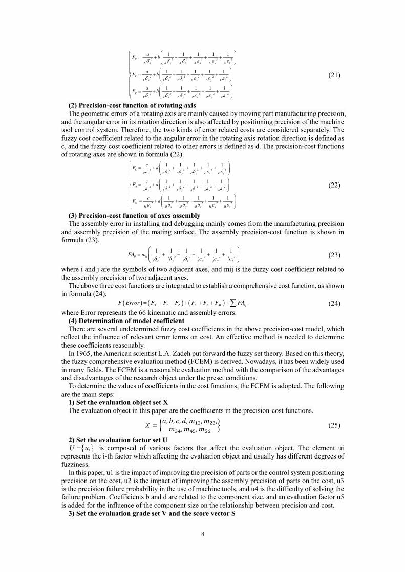
(1) Precision-cost function of linear axis
The geometric errors of a linear axis are mainly caused by moving part manufacturing precision, and the position error in its moving direction is also affected by the positioning precision of control system. Therefore, the two kinds of error related costs are considered separately. The fuzzy cost coefficient related to the position error in the moving direction of a linear axis is set as a, and the fuzzy cost coefficient related to other errors is set as b. The precision-cost functions of linear axes are shown in formula (21).
8
2 2 2 2 2 2
2 2 2 2 2 2
2 2 2 2 2 2
1 1 1 1 1
1 1 1 1 1
1 1 1 1 1
X
X x X y X z X x X y X z
Y
Y y Y x Y z Y x Y y Y z
Z
Y z Z x Z y Z x Z y Z z
aF b
aF b
aF b
(21)
(2) Precision-cost function of rotating axis
The geometric errors of a rotating axis are mainly caused by moving part manufacturing precision, and the angular error in its rotation direction is also affected by positioning precision of the machine tool control system. Therefore, the two kinds of error related costs are considered separately. The fuzzy cost coefficient related to the angular error in the rotating axis rotation direction is defined as c, and the fuzzy cost coefficient related to other errors is defined as d. The precision-cost functions of rotating axes are shown in formula (22).
2 2 2 2 2 2
2 2 2 2 2 2
2 2 2 2 2 2
1 1 1 1 1
1 1 1 1 1
1 1 1 1 1
C
C z C x C y C z C x C y
A
A x A x A y A z A y A z
M
M y M x M y M z M x M z
cF d
cF d
cF d
(22)
(3) Precision-cost function of axes assembly
The assembly error in installing and debugging mainly comes from the manufacturing precision and assembly precision of the mating surface. The assembly precision-cost function is shown in formula (23).
2 2 2 2 2 2
1 1 1 1 1 1ij ij i i i i i i
j x j y j z j x j y j z
FA m
(23)
where i and j are the symbols of two adjacent axes, and mij is the fuzzy cost coefficient related to the assembly precision of two adjacent axes.
The above three cost functions are integrated to establish a comprehensive cost function, as shown in formula (24).
X Y Z C A M ijF Error F F F F F F FA (24) where Error represents the 66 kinematic and assembly errors.
(4) Determination of model coefficient There are several undetermined fuzzy cost coefficients in the above precision-cost model, which
reflect the influence of relevant error terms on cost. An effective method is needed to determine these coefficients reasonably.
In 1965, the American scientist L.A. Zadeh put forward the fuzzy set theory. Based on this theory, the fuzzy comprehensive evaluation method (FCEM) is derived. Nowadays, it has been widely used in many fields. The FCEM is a reasonable evaluation method with the comparison of the advantages and disadvantages of the research object under the preset conditions.
To determine the values of coefficients in the cost functions, the FCEM is adopted. The following are the main steps:
1) Set the evaluation object set X
The evaluation object in this paper are the coefficients in the precision-cost functions. 𝑋 = {𝑎, 𝑏, 𝑐, 𝑑, 𝑚12, 𝑚23,𝑚34, 𝑚45, 𝑚56 } (25)
2) Set the evaluation factor set U
iU u is composed of various factors that affect the evaluation object. The element ui represents the i-th factor which affecting the evaluation object and usually has different degrees of fuzziness.
In this paper, u1 is the impact of improving the precision of parts or the control system positioning precision on the cost, u2 is the impact of improving the assembly precision of parts on the cost, u3 is the precision failure probability in the use of machine tools, and u4 is the difficulty of solving the failure problem. Coefficients b and d are related to the component size, and an evaluation factor u5 is added for the influence of the component size on the relationship between precision and cost.
3) Set the evaluation grade set V and the score vector S

9
jV v is composed of all kinds of results that may be made to the evaluation object, and the element vj represents the j-th evaluation grade. Each evaluation grade in V is given a score to form a score vector S with si as the weight of evaluation grade vi in V. The evaluation grade and score of each factor are shown in Table 3. Here we have
S = [5,4,3,2,1] (26) 4) Set the weight vector A
A is the weight vector of the factor ui in the factor set U, determined based on the domain knowledge and expert experience.
According to the structural characteristics of CNC-LGHM and the opinions of relevant experts in design and maintenance, the evaluation weight vector in this paper is set as
A = [0.4, 0.2, 0.1, 0.3] (27) The coefficient b and d also consider the component size factor u5, and its evaluation weight
vector is set as
A = [0.4, 0.2, 0.1, 0.2, 0.1] (28)
Table 3 Factor evaluation grade and score
Factor Evaluation grade Score
u1
u2
Most cost increase 5
More cost increase 4
Moderate cost increase 3
Less cost increase 2
Little cost increase 1
u3
Very high failure probability 5
High failure probability 4
General failure probability 3
Low failure probability 2
Very low failure probability 1
u4
Very difficult 5
Difficult 4
Moderate 3
Easy 2
Very easy. 1
u5
Very great impact 5
Great impact 4
General impact 3
Small impact 2
Very small impact 1
5) Set the fuzzy comprehensive evaluation matrix R
ijR r is constructed according to the domain knowledge and expert experience, where rij is
the membership degree of the factor ui in the evaluation factor set U to the evaluation grade vj in the evaluation set V.
Take parameter a as an example. According to the experience of domain experts, the comprehensive evaluation matrix R is determined as follows
0 0 0.2 0.2 0.6
0 0 0.2 0.4 0.4
0 0 0.6 0.4 0
0 0.2 0.2 0.4 0.2
R
(29)
6) Establish evaluation model The fuzzy comprehensive evaluation model is defined by equation (30).
B A R (30) For coefficients a, it can be obtained

10
0,0.06,0.24,0.32,0.38B (31) 7) Calculate the score
The total score of fuzzy comprehensive evaluation is calculated by equation (32). TF B S (32)
For coefficients a, it can be obtained
= 1.98a F (33) In the same way, other coefficients in the precision-cost model can be obtained. All the results
are shown in Table 4.
Table 4 Precision-cost model coefficients
Coefficient Value
a 1.98
b 1.7
c 1.83
d 1.5
m12 1.4
m23 1.9
m34 1.3
m45 1.65
m56 1.34
3.3. Multi-object optimization model of precision allocation
So far, the comprehensive error model and fuzzy precision-cost model of hobbing machine have been established. The machine tools precision allocation is realized with precision-cost objective comprehensive optimization. Therefore, two kinds of objective function of optimal precision and optimal cost should be established respectively to construct a multi-objective optimization model.
(1) Optimal precision object function
The precision allocation optimization in this paper aims at improving the precision, so the optimization goal is the overall precision of the machine tool. As described in Section 3.1, there are 6 parameters describing the machining precision of a large NC hobbing machine tool, i.e, Iδx, Iδy, Iδz, Iεx, Iεy and Iεz. As the unit and value of Iδx, Iδy and Iδz are quite different from that of Iεx, Iεy and Iεz., the two kinds of precision parameters could not be directly and simply superimposed when constructing the objective function. Therefore, two objective functions are constructed.
22 2
x y zIp Error I I I (34)
22 2
x y zIa Error I I I (35)
(2) Optimal cost object function
The manufacturing cost is an inevitable problem in the production of machine tool. It is unrealistic to increase the manufacturing cost indefinitely for the purpose of improving precision, so the manufacturing cost of machine tool also needs to be controlled and optimized. The cost optimization object function is F(Error) shown in formula (24).
Then the precision allocation optimization model of transmission chain of CNC-LGHM based on precision-cost comprehensive optimization can be established as
min [ , , ]
:
0, X
,2 2
0,
,4 4
T
x
y
z
A
V f Error Ip Error Ia Error F Error
Subject to
S S
SY SYS
S SZ
(36)
where SX, SY and SZ represent the maximum stroke of X, Y and Z axes respectively, Sx, Sy, Sz

11
and θA is the moving position of machine tool moving axe. Since the machine tool hob spindle and the C-axis of the worktable rotate 360 degrees in the machining process, there is no need to restrict these two items.
4. Solution and decision of multi-objective optimization model
There is usually a solution set when solving multi-objective optimization problems. As far as the objective function is concerned, these solutions cannot be compared. In order to solve the multi-objective optimization problem, it is necessary to find as many non-dominant solutions as possible. The most satisfactory optimization results should be selected objectively according to the design requirements and practical engineering experience.
This paper adopts the multi-objective grey wolf optimization (MOGWO) algorithm to solve the precision allocation optimization model, and the TOPSIS multi-objective decision-making method for selecting optimal solutions to meet the actual needs from the obtained Pareto solution set.
4.1. Optimization model solution
Mirjalili proposed GWO which is an intelligent optimization algorithm in 2014[43]. There is a cooperative mechanism in the predation of gray wolves in nature. GWO simulates this behavior for optimization purposes. GWO algorithm is simple in structure and easy to implement, with less parameter adjustment. In order to achieve the balance between global search and local optimization, GWO adopts information feedback mechanism and sets adaptive convergence factor, which makes it have good accuracy and convergence speed in solving problems.
Wolves in GWO include four kinds of wolves called α, β, δ and ω wolfs. The α, β and δ wolf are the top three solutions, and ω wolves are the candidate solutions in the search space. In the process of solving the optimal solution, all ω wolves tracking the location of α, β and δ wolf to gradually approach the optimal solution, as shown in Fig. 3.
Fig. 3 Wolf ω location update
In 2016, the MOGWO algorithm was presented by Mirjalili et al.[44]. The Pareto optimal solution is saved and retrieved by a fixed size external archive on the basis of GWO. In the multi-objective search space, the grey wolf hunting behavior is simulated with the archive to define the social level to resolve multi-objective optimization problem.
In this paper, MOGWO is adopted as a solving method for the precision-cost multi-objective optimization model established in Section 3. Each gray wolf in the gray wolf group represents a precision allocation. Ip, Ia and F are calculated by using the comprehensive error model and fuzzy cost model to evaluate the fitness of each gray wolf, select the current non-dominated solution, and finally obtain the Pareto solution set of precision allocation after continuous updating and iteration.
In particular, according to the comprehensive error model, Ip and Ia are related not only to the precision, but also to the position of moving axes. For a precision allocation, i.e. a gray wolf, the worst-case machine tool comprehensive errors caused by them must be considered. Therefore, when solving Ip and Ia, it is necessary to search the space position that makes Ip and Ia reach the maximum value in the effective workspace of the machine tool moving axes, and take the maximum Ip and Ia

12
as the fitness of the gray wolf. In this work, GWO algorithm is used to solve Ip and Ia with the axes position (SX,SY,SZ,θA,θC,θM) as variables.
4.2. Decision making of optimization
Because the solution of the multi-objective model is a solution set, and the results in the solution set have their own advantages and disadvantages, a systematic method is needed to select the solution. For multi-objective decision analysis, TOPSIS which first presented by C.L.Hwang et al. in 1981 is an effective and commonly used method. It is a ranking method based on the proximity between idealized objectives and evaluation objects to evaluate the existing objects with relative advantages or disadvantages. This method only needs to guarantee the monotonicity of each utility function to approach the ideal solution.
This paper selects the non-dominated solutions based on TOPSIS method. According to the multi-objective model, the decision scheme set D = {d1, d2,..., dm} is defined by the Pareto solution set. The variables to measure the scheme attributes include fuzzy cost F, precision index Ip and Ia. For each scheme di in set D, three attribute values composed a vector [ai1, ai2, ai3], which uniquely represents a scheme.
The main decision-making steps are as follows: (1) Setting up the decision matrix A
A=(aij)m×3 (37) Decision-making results and evaluation results will be affected by the differences of decision-
making attribute types, attribute value sizes and attribute dimensions, so it is necessary to standardize the attribute values first. This paper adopts the linear normalization method. The normalized decision matrix is set as
B=(bij)m×3 (38) where
1max
ij
ij
iji
ab
a (39)
(2) Construction of the weighted canonical matrix C
C=(cij)m×3 (40)
1,2,..., ; 1,2,3ij j ijc w b i m j (41)
where w=[w1,w2 ,w3]T is the weight vector given by decision makers. (3) Calculation of ideal solutions of positive and negative
* minj iji
c c (42)
0 maxj iji
c c (43)
(4) Calculation of the distance between schemes and ideal solutions
2* *
1
1,2,...,n
i ij j
j
s c c i m
(44)
20 0
1
1,2,...,n
i ij j
j
s c c i m
(45)
(5) Comprehensive evaluation value calculation
0
*
0 *1,2,...,i
i
i i
sf i m
s s
(46)
(6) Make the decision
Sort all the schemes according to the comprehensive evaluation value from large to small.
13
Generally, select the scheme with the largest comprehensive evaluation value as the optimal precision allocation scheme.
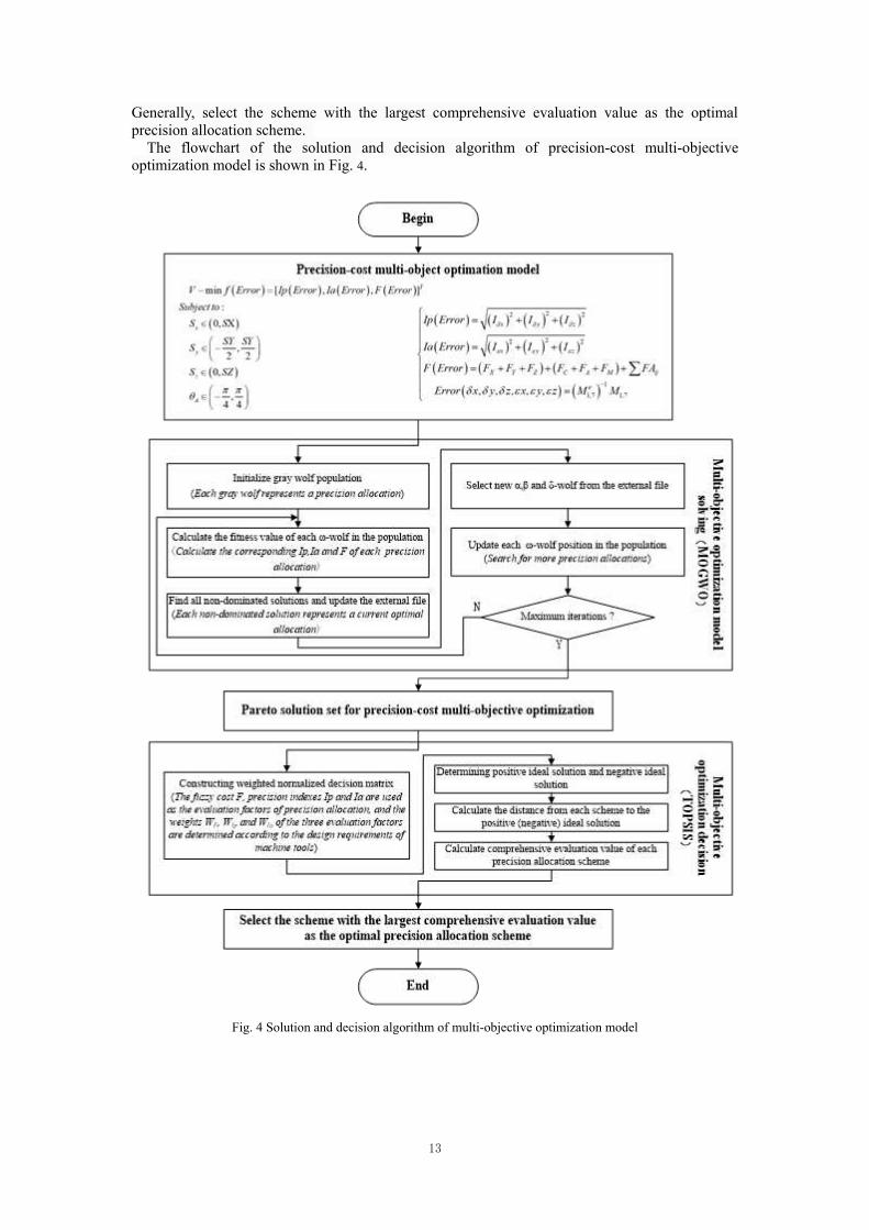
The flowchart of the solution and decision algorithm of precision-cost multi-objective optimization model is shown in Fig. 4.
Fig. 4 Solution and decision algorithm of multi-objective optimization model

14
5. Case study
5.1. Optimal solution
The parameters of the large gear hobbing machine shown in Fig. 5 are shown in Table 5.
Fig. 5 CNC-LGHM
Table 5 Machine tool parameters
Design parameters Values
Spindle speed range 20-220r/min
Worktable maximum speed 8r/min
X-axis travel 100mm-1000mm
Y-axis travel 0-300mm
Z-axis travel 470mm-1770mm
Tool holder rotation angle ±45°
MOGWO is used to optimize the precision allocation of transmission chain. The main parameters of the algorithm are set as follows: The iteration number is 500. The size of gray wolf population is 100. And the number of non-dominated solutions stored by external files is 20. The results are shown in Fig. 6. The Pareto solution set of fuzzy manufacturing cost and precisions are shown in Table 6.
(a) Fuzzy cost vs Ip (b) Fuzzy cost vs Ia
Fig. 6 MOGWO operation results
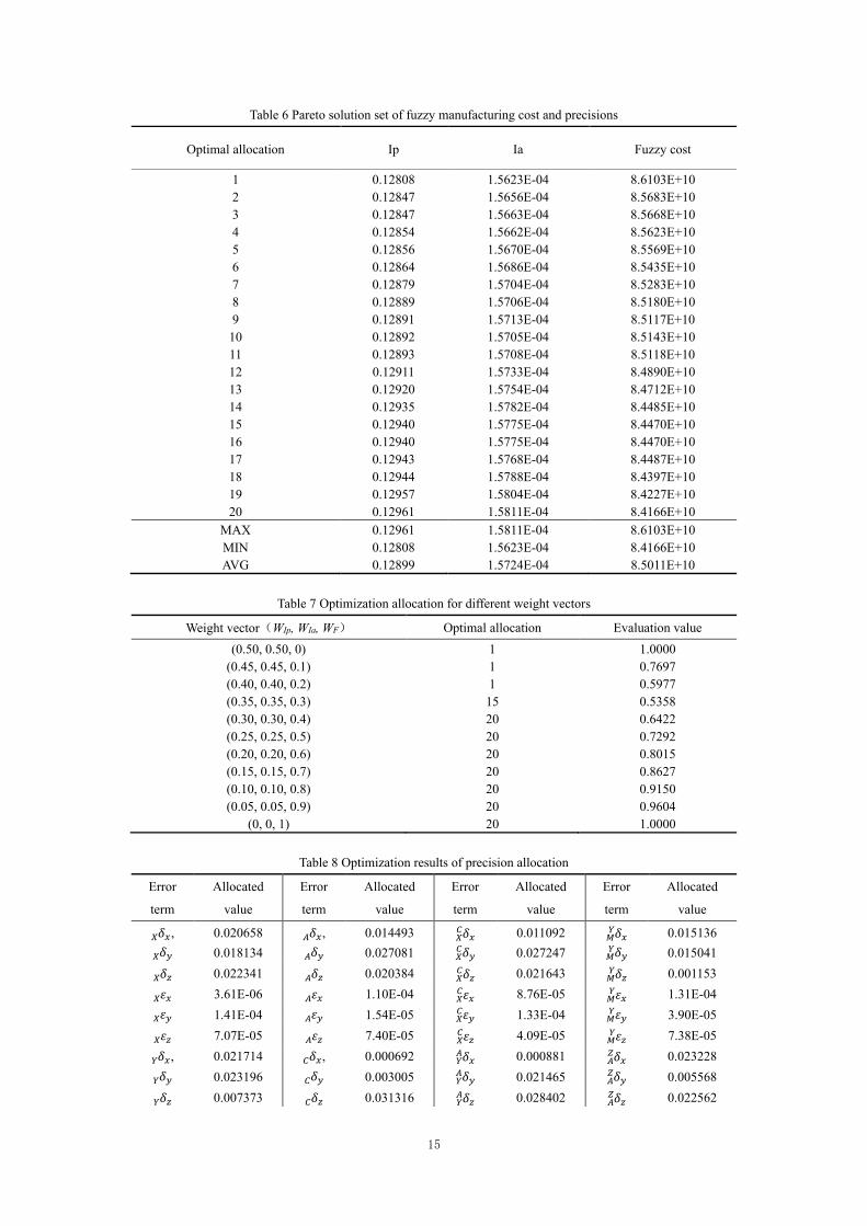
A suitable solution is selected from the optimal solution set for different weight vector by using TOPSIS method as shown in Table 7, where WF is the weight of fuzzy cost, WIp and WIa are the weight of Ip and Ia. Because Ip and Ia reflect the machining precision of machine tools, and their optimization objectives are the same, they are regarded as one in terms of weight selection, and the same weight is selected.
Taking the optimal allocation 15 as example, the optimization results of precision allocation is shown in Table 8.
15
Table 6 Pareto solution set of fuzzy manufacturing cost and precisions
Optimal allocation Ip Ia Fuzzy cost
1 0.12808 1.5623E-04 8.6103E+10
2 0.12847 1.5656E-04 8.5683E+10
3 0.12847 1.5663E-04 8.5668E+10
4 0.12854 1.5662E-04 8.5623E+10
5 0.12856 1.5670E-04 8.5569E+10
6 0.12864 1.5686E-04 8.5435E+10
7 0.12879 1.5704E-04 8.5283E+10
8 0.12889 1.5706E-04 8.5180E+10
9 0.12891 1.5713E-04 8.5117E+10
10 0.12892 1.5705E-04 8.5143E+10
11 0.12893 1.5708E-04 8.5118E+10
12 0.12911 1.5733E-04 8.4890E+10
13 0.12920 1.5754E-04 8.4712E+10
14 0.12935 1.5782E-04 8.4485E+10
15 0.12940 1.5775E-04 8.4470E+10
16 0.12940 1.5775E-04 8.4470E+10
17 0.12943 1.5768E-04 8.4487E+10
18 0.12944 1.5788E-04 8.4397E+10
19 0.12957 1.5804E-04 8.4227E+10
20 0.12961 1.5811E-04 8.4166E+10
MAX 0.12961 1.5811E-04 8.6103E+10
MIN 0.12808 1.5623E-04 8.4166E+10
AVG 0.12899 1.5724E-04 8.5011E+10
Table 7 Optimization allocation for different weight vectors
Weight vector(WIp, WIa, WF) Optimal allocation Evaluation value
(0.50, 0.50, 0) 1 1.0000
(0.45, 0.45, 0.1) 1 0.7697
(0.40, 0.40, 0.2) 1 0.5977
(0.35, 0.35, 0.3) 15 0.5358
(0.30, 0.30, 0.4) 20 0.6422
(0.25, 0.25, 0.5) 20 0.7292
(0.20, 0.20, 0.6) 20 0.8015
(0.15, 0.15, 0.7) 20 0.8627
(0.10, 0.10, 0.8) 20 0.9150
(0.05, 0.05, 0.9) 20 0.9604
(0, 0, 1) 20 1.0000
Table 8 Optimization results of precision allocation
Error
term
Allocated
value
Error
term
Allocated
value
Error
term
Allocated
value
Error
term
Allocated
value 𝛿𝑥𝑋 , 0.020658 𝛿𝑥𝐴 , 0.014493 𝛿𝑥𝑋𝐶 0.011092 𝛿𝑥𝑀𝑌 0.015136 𝛿𝑦𝑋 0.018134 𝛿𝑦𝐴 0.027081 𝛿𝑦𝑋𝐶 0.027247 𝛿𝑦𝑀𝑌 0.015041 𝛿𝑧𝑋 0.022341 𝛿𝑧𝐴 0.020384 𝛿𝑧𝑋𝐶 0.021643 𝛿𝑧𝑀𝑌 0.001153 𝜀𝑥𝑋 3.61E-06 𝜀𝑥𝐴 1.10E-04 𝜀𝑥𝑋𝐶 8.76E-05 𝜀𝑥𝑀𝑌 1.31E-04 𝜀𝑦𝑋 1.41E-04 𝜀𝑦𝐴 1.54E-05 𝜀𝑦𝑋𝐶 1.33E-04 𝜀𝑦𝑀𝑌 3.90E-05 𝜀𝑧𝑋 7.07E-05 𝜀𝑧𝐴 7.40E-05 𝜀𝑧𝑋𝐶 4.09E-05 𝜀𝑧𝑀𝑌 7.38E-05 𝛿𝑥𝑌 , 0.021714 𝛿𝑥𝐶 , 0.000692 𝛿𝑥𝑌𝐴 0.000881 𝛿𝑥𝐴𝑍 0.023228 𝛿𝑦𝑌 0.023196 𝛿𝑦𝐶 0.003005 𝛿𝑦𝑌𝐴 0.021465 𝛿𝑦𝐴𝑍 0.005568 𝛿𝑧𝑌 0.007373 𝛿𝑧𝐶 0.031316 𝛿𝑧𝑌𝐴 0.028402 𝛿𝑧𝐴𝑍 0.022562
16
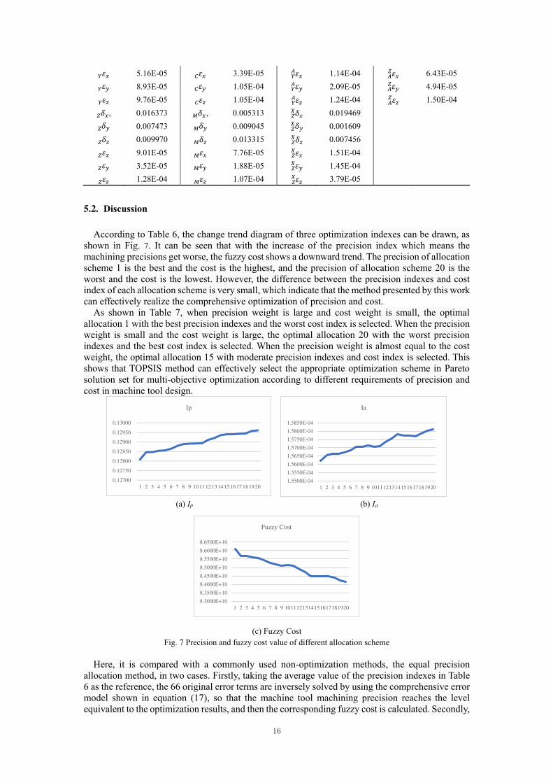
𝜀𝑥𝑌 5.16E-05 𝜀𝑥𝐶 3.39E-05 𝜀𝑥𝑌𝐴 1.14E-04 𝜀𝑥𝐴𝑍 6.43E-05 𝜀𝑦𝑌 8.93E-05 𝜀𝑦𝐶 1.05E-04 𝜀𝑦𝑌𝐴 2.09E-05 𝜀𝑦𝐴𝑍 4.94E-05 𝜀𝑧𝑌 9.76E-05 𝜀𝑧𝐶 1.05E-04 𝜀𝑧𝑌𝐴 1.24E-04 𝜀𝑧𝐴𝑍 1.50E-04 𝛿𝑥𝑍 , 0.016373 𝛿𝑥𝑀 , 0.005313 𝛿𝑥𝑍𝑋 0.019469 𝛿𝑦𝑍 0.007473 𝛿𝑦𝑀 0.009045 𝛿𝑦𝑍𝑋 0.001609 𝛿𝑧𝑍 0.009970 𝛿𝑧𝑀 0.013315 𝛿𝑧𝑍𝑋 0.007456 𝜀𝑥𝑍 9.01E-05 𝜀𝑥𝑀 7.76E-05 𝜀𝑥𝑍𝑋 1.51E-04 𝜀𝑦𝑍 3.52E-05 𝜀𝑦𝑀 1.88E-05 𝜀𝑦𝑍𝑋 1.45E-04 𝜀𝑧𝑍 1.28E-04 𝜀𝑧𝑀 1.07E-04 𝜀𝑧𝑍𝑋 3.79E-05
5.2. Discussion
According to Table 6, the change trend diagram of three optimization indexes can be drawn, as shown in Fig. 7. It can be seen that with the increase of the precision index which means the machining precisions get worse, the fuzzy cost shows a downward trend. The precision of allocation scheme 1 is the best and the cost is the highest, and the precision of allocation scheme 20 is the worst and the cost is the lowest. However, the difference between the precision indexes and cost index of each allocation scheme is very small, which indicate that the method presented by this work can effectively realize the comprehensive optimization of precision and cost.
As shown in Table 7, when precision weight is large and cost weight is small, the optimal allocation 1 with the best precision indexes and the worst cost index is selected. When the precision weight is small and the cost weight is large, the optimal allocation 20 with the worst precision indexes and the best cost index is selected. When the precision weight is almost equal to the cost weight, the optimal allocation 15 with moderate precision indexes and cost index is selected. This shows that TOPSIS method can effectively select the appropriate optimization scheme in Pareto solution set for multi-objective optimization according to different requirements of precision and cost in machine tool design.
(a) Ip (b) Ia
(c) Fuzzy Cost Fig. 7 Precision and fuzzy cost value of different allocation scheme
Here, it is compared with a commonly used non-optimization methods, the equal precision allocation method, in two cases. Firstly, taking the average value of the precision indexes in Table 6 as the reference, the 66 original error terms are inversely solved by using the comprehensive error model shown in equation (17), so that the machine tool machining precision reaches the level equivalent to the optimization results, and then the corresponding fuzzy cost is calculated. Secondly,
0.12700
0.12750
0.12800
0.12850
0.12900
0.12950
0.13000
1 2 3 4 5 6 7 8 9 1011121314151617181920
Ip
1.5500E-04
1.5550E-04
1.5600E-04
1.5650E-04
1.5700E-04
1.5750E-04
1.5800E-04
1.5850E-04
1 2 3 4 5 6 7 8 9 1011121314151617181920
Ia
8.3000E+10
8.3500E+10
8.4000E+10
8.4500E+10
8.5000E+10
8.5500E+10
8.6000E+10
8.6500E+10
1 2 3 4 5 6 7 8 9 1011121314151617181920
Fuzzy Cost
17
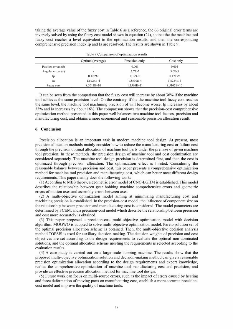
taking the average value of the fuzzy cost in Table 6 as a reference, the 66 original error terms are inversely solved by using the fuzzy cost model shown in equation (24), so that the the machine tool fuzzy cost reaches a level equivalent to the optimization results, and then the corresponding comprehensive precision index Ip and Ia are resolved. The results are shown in Table 9.
Table 9 Comparison of optimization results
Optimal(average) Precision only Cost only
Position errors (δ) - 0.001 0.004
Angular errors (ε) - 2.7E-5 3.0E-5
Ip 0.12899 0.12976 0.17179
Ia 1.5724E-4 1.5510E-4 1.8234E-4
Fuzzy cost 8.5011E+10 1.1590E+11 8.5102E+10
It can be seen from the comparison that the fuzzy cost will increase by about 36% if the machine tool achieves the same precision level. On the contrary, if the the machine tool fuzzy cost reaches the same level, the machine tool machining precision of will become worse. Ip increases by about 33% and Ia increases by about 16%. The comparison shows that the precision-cost comprehensive optimization method presented in this paper well balances two machine tool factors, precision and manufacturing cost, and obtains a more economical and reasonable precision allocation result.
6. Conclusion
Precision allocation is an important task in modern machine tool design. At present, most precision allocation methods mainly consider how to reduce the manufacturing cost or failure cost through the precision optimal allocation of machine tool parts under the premise of given machine tool precision. In these methods, the precision design of machine tool and cost optimization are considered separately. The machine tool design precision is determined first, and then the cost is optimized through precision allocation. The optimization effect is limited. Considering the reasonable balance between precision and cost, this paper presents a comprehensive optimization method for machine tool precision and manufacturing cost, which can better meet different design requirements. This paper mainly does the following work:
(1) According to MBS theory, a geometric error model of CNC-LGHM is established. This model describes the relationship between gear hobbing machine comprehensive errors and geometric errors of motion axes and assembly errors between axes.
(2) A multi-objective optimization model aiming at minimizing manufacturing cost and machining precision is established. In the precision-cost model, the influence of component size on the relationship between precision and manufacturing cost is considered. The model parameters are determined by FCEM, and a precision-cost model which describe the relationship between precision and cost more accurately is obtained.
(3) This paper proposed a precision-cost multi-objective optimization model with decision algorithm. MOGWO is adopted to solve multi-objective optimization model. Pareto solution set of the optimal precision allocation scheme is obtained. Then, the multi-objective decision analysis method TOPSIS is used for auxiliary decision-making. The decision weights of precision and cost objectives are set according to the design requirements to evaluate the optimal non-dominated solutions, and the optimal allocation scheme meeting the requirements is selected according to the evaluation results.
(4) A case study is carried out on a large-scale hobbing machine. The results show that the proposed multi-objective optimization solution and decision-making method can give a reasonable precision optimization allocation according to the design requirements and expert knowledge, realize the comprehensive optimization of machine tool manufacturing cost and precision, and provide an effective precision allocation method for machine tool design.
(5) Future work can focus on multi-source errors, such as the impact of errors caused by heating and force deformation of moving parts on manufacturing cost, establish a more accurate precision-cost model and improve the quality of machine tools.
18
Reference
[1] Sheng Hongliang, Yang Wenyun. (1990) Development direction and key of precision distribution theory for modern mechanism. Optical technology, (5): 33-36.
[2] Hallmann M , Schleich B , Wartzack S . (2020) From tolerance allocation to tolerance-cost optimization: a comprehensive literature review. The International Journal of Advanced Manufacturing Technology, 107(1):1-54. HTTPS://DOI.ORG/10.1007/s00170-020-05254-5
[3] Sheng Hongliang, Yang Wenyun. (1991) Value analysis method of mechanism precision distribution. Optical technology, (05): 3-6
[4] Dong Z, Hu W, Xue D. (1994) New Production Cost-Tolerance Models for Tolerance Synthesis. Asme J Eng Industry, 116(2):199-206. HTTPS://DOI.ORG/10.1115/1.2901931
[5] Feng C X , Kusiak A . Robust (1997) Tolerance Design With the Integer Programming Approach. Journal of Manufacturing Science and Engineering, 119(4A):603. HTTPS://DOI.ORG/10.1115/1.2831193
[6] Diplaris S C , Sfantsikopoulos M M . (2000) Cost-Tolerance Function. A New Approach for Cost Optimum Machining Accuracy. International Journal of Advanced Manufacturing Technology, 16(1):32-38. HTTPS://DOI.ORG/10.1007/PL00013129
[7] Rao S, Wu W. (2005) Optimum tolerance allocation in mechanical assemblies using an interval method.
Engineering Optimization, 37(3): 237-257. HTTPS://DOI.ORG/10.1080/0305215512331328240
[8] Krishna A G , Rao K M . (2006) Simultaneous optimal selection of design and manufacturing tolerances with different stack-up conditions using scatter search. International Journal of Advanced Manufacturing Technology, 30(3-4):328-333. HTTPS://DOI.ORG/10.1007/s00170-005-0059-0
[9] Huang X , Ding W , Hong R . (2006) Research on accuracy design for remanufactured machine tools International Technology & Innovation Conference., Hangzhou
[10] Kang Fang, fan Jinwei. (2008) Optimal allocation method for manufacturing precision of CNC machine tools. Mechanical science and technology, 27 (5): 588-591.
[11] Muthu P , Dhanalakshmi V , Sankaranarayanasamy K . (2009) Optimal tolerance design of assembly for minimum quality loss and manufacturing cost using metaheuristic algorithms. The International Journal of Advanced Manufacturing Technology, 44(11-12):1154-1164. HTTPS://DOI.ORG/10.1007/s00170-009-1930-1
[12] Sanz-Lobera A , MA Sebastián, JM Pérez. (2010) New cost-tolerance model for mechanical part design. International Journal of Advanced Manufacturing Technology, 51(5-8):421-430. HTTPS://DOI.ORG/10.1007/s00170-010-2661-z
[13] Sarina, Zhang S, Xu J. (2013) Transmission system accuracy optimum allocation for multiaxis machine tools’ scheme design. Proceedings of Institution of Mechanical Engineers, Part C: Journal of Mechanical Engineering Science, 227(12): 2762-2779. HTTPS://DOI.ORG/10.1177/0954406213479723
[14] Yu Zhimin, Liu Zijian, AI Yandi, et al. (2013) Geometric error modeling and precision allocation based on reliability theory for large CNC gantry guide rail grinder. Journal of mechanical engineering, 49 (17): 142-151. HTTPS://DOI.ORG/10.3901/JME.2013.17.142
[15] Xing Yuan, Zhang Lianhong, he Baiyan, et al. (2014) Precision inverse design method for CNC machine tools based on multi-body theory. Journal of agricultural machinery, 45 (3): 282-287.
[16] Cai L , Zhang Z , Cheng Q , et al. (2015) A geometric accuracy design method of multi-axis NC machine tool for improving machining accuracy reliability. Eksploatacja i Niezawodnosc - Maintenance and Reliability, 17(1):143-155. HTTPS://DOI.ORG/10.17531/ein.2015.1.19
[17] Cheng Q , Zhang Z , Zhang G , et al. (2015) Geometric accuracy allocation for multi-axis CNC machine tools based on sensitivity analysis and reliability theory. Proceedings of the Institution of Mechanical Engineers, Part C: Journal of Mechanical Engineering Science. HTTPS://DOI.ORG/10.1177/0954406214542491
[18] Guo J , Liu Z , Li B , et al. (2015) Optimal tolerance allocation for precision machine tools in consideration of measurement and adjustment processes in assembly. International Journal of Advanced Manufacturing Technology, 80(9-12):1625-1640. HTTPS://DOI.ORG/10.1007/s00170-015-7122-2
[19] Yang Z , Zhu Y , Ren H , et al. (2015) Comprehensive reliability allocation method for CNC lathes based on cubic transformed functions of failure mode and effects analysis. Chinese Journal of Mechanical Engineering, 28:315–324. HTTPS://DOI.ORG/10.3901/CJME.2015.0105.004
[20] Y. M. Zhao, D. S. Liu & Z. J. Wen, (2016) Optimal tolerance design of product based on service quality loss. International Journal of Advanced Manufacturing Technology, 2016, 82(9-12):1715-1724. HTTPS://DOI.ORG/10.1007/s00170-015-7480-9
[21] Zhang, Y., Ji, S., Zhao, J. et al. (2016) Tolerance analysis and allocation of special machine tool for manufacturing globoidal cams. Int J Adv Manuf Technol 87:1597–1607. HTTPS://DOI.ORG/10.1007/s00170-

19
016-8558-8
[22] Zhang Z , Liu Z , Qiang C , et al. (2016) An approach of comprehensive error modeling and accuracy allocation for the improvement of reliability and optimization of cost of a multi-axis NC machine tool. International Journal of Advanced Manufacturing Technology, 89(1-4):1-19. HTTPS://DOI.ORG/10.1007/s00170-016-8981-x
[23] Liu Peng, Hong Jun, Liu Zhigang, et al. (2016) Research on machine tool tolerance allocation using adaptive genetic algorithm. Journal of Xi'an Jiaotong University, 50 (1): 115-123. HTTPS://DOI.ORG/10.1007/s00170-016-8981-x
[24] Cai L , Zhang Z , Qiang C , et al. (2016) An approach to optimize the machining accuracy retainability of multi-axis NC machine tool based on robust design. Precision Engineering, 43:370-386. HTTPS://DOI.ORG/10.1016/j.precisioneng.2015.09.001
[25] Zhang Z , Cai L , Cheng Q , et al. (2016) A geometric error budget method to improve machining accuracy reliability of multi-axis machine tools. Journal of Intelligent Manufacturing, 30:495–519. HTTPS://DOI.ORG/10.1007/s10845-016-1260-8
[26] Balamurugan C , Saravanan A , Babu P D , et al. (2016) Concurrent optimal allocation of geometric and process tolerances based on the present worth of quality loss using evolutionary optimisation techniques. Research in Engineering Design, 28(2):1-18. HTTPS://DOI.ORG/10.1007/s00163-016-0230-7
[27] Cheng Bin Bin, Huang Mei FA, Wang Zhi Yue, et al. (2016) Optimal allocation of assembly tolerance based on actual working conditions. Mechanical design and research, 32 (2): 123-126.
[28] Zhang Z, Liu Z, Cheng Q, et al. (2017) An approach of comprehensive error modeling and accuracy allocation for the improvement of reliability and optimization of cost of a multi-axis NC machine tool. The International Journal of Advanced Manufacturing Technology, 89: 561–579. HTTPS://DOI.ORG/10.1007/s00170-016-8981-x
[29] Tlija M , Ghali M , Aifaoui N . (2019) Integrated CAD tolerancing model based on difficulty coefficient evaluation and Lagrange multiplier. International Journal of Advanced Manufacturing Technology, 101:2519–2532. HTTPS://DOI.ORG/10.1007/s00170-018-3140-1
[30] Wu Jian, (2018) research on optimal allocation method of geometric precision for precision horizontal machining center, Shanghai: Shanghai Jiaotong University
[31] He C , Zhang S , Qiu L , et al. (2020) Statistical tolerance allocation design considering form errors based on rigid assembly simulation and deep Q-network. The International Journal of Advanced Manufacturing Technology, 111(11-12):1-17. HTTPS://DOI.ORG/10.1007/s00170-020-06283-w
[32] Fan J , Tao H , Pan R , et al. (2020) Optimal tolerance allocation for five-axis machine tools in consideration of deformation caused by gravity. International Journal of Advanced Manufacturing Technology, 2020, 111(1-2):1-12. HTTPS://DOI.ORG/10.1007/s00170-020-06096-x
[33] Hocken RJ, Simpson JA, Borchardt B, Lazar J, Reeve C, Stein P (1977) Three dimensional metrology. Journal
of Ann. CIRP 26(2):403–408
[34] Dufour P, Groppetti R. (2006) Computer aided precision improvement in large NC machine-tools. In
Proceedings of the 2006 International Conference on the MTDR 22: 611–618.
[35] Portman VT (1982) A universal method for calculating the precision of mechanical devices. J Sov Eng Res
1(7):11–15
[36] Kiridena V, Ferreira PM (1993) Mapping the effects of positioning errors on the volumetric precision of five-
axis CNC machine tools. Int J Mach Tools Manuf 33(3):417–437
[37] Fu Guoqiang. (2016) Research on Geometric Error Modeling and Compensation of CNC Machine Tools Based
on the Product-of-exponential Theory and Transforming differential Changes between Corrdinate Frames.
Hangjou, Zhenjiang University
[38] Chen Jianxiong, Lin Shuwen. (2014) Geometric Error Decoupling for Multi-axis CNC Machines Based on
Differential Transformation. China Mechanical Engineering. 25(17):2290-2294
[39] Wang SX, Yun JT and Zhang ZF. (2003) Modeling and compensation technique for the geometric errors of
five-axis CNC machine tools. Chin J Mech Eng 16: 197–201.
[40] Shi XL, Liu HL, Li H, Liu C, Tan GY (2016) Comprehensive error measurement and compensation method
for equivalent cutting forces. Int J Adv Manuf Technol 85(1–4):149–156.
HTTPS://DOI.ORG/10.1007/s00170-015-7789-4
[41] Shi YG, Zhao XY, Zhang HJ, Nie YX, Zhang DW (2016) A new top-down design method for the stiffness of
precision machine tools. Int J Adv Manuf Technol 83(9–12):1887–1904.
HTTPS://DOI.ORG/10.1007/s00170-015-7705-y
[42] Shouli Sun, Shilong Wang, Yawen Wang, Teik C. Lim, Yong Yang. (2018) Prediction and optimization of hobbing gear geometric deviations, Mechanism and Machine Theory, 120:288-301. HTTPS://DOI.ORG/10.1016/j.mechmachtheory.2017.09.002

20
[43] Seyedali Mirjalili, Seyed Mohammad Mirjalili, Andrew Lewis. (2014) Grey Wolf Optimizer. Advances in Engineering Software, 69:46-61
[44] Seyedali Mirjalili, Shahrzad Saremi, Seyed Mohammad Mirjalilic, et al. (2015) Multi-objective grey wolf optimizer: A novel algorithm for multi-criterion optimization. Expert Systems with Applications, 47:106-119. HTTPS://DOI.ORG/10.1016/j.eswa.2015.10.039