precision motion control for fiber optics and silicon ... · precision motion control for fiber...
TRANSCRIPT
aerotech.com
Precision Motion Control for
Fiber Optics and Silicon Photonics
aerotech.com
aerotech.com2
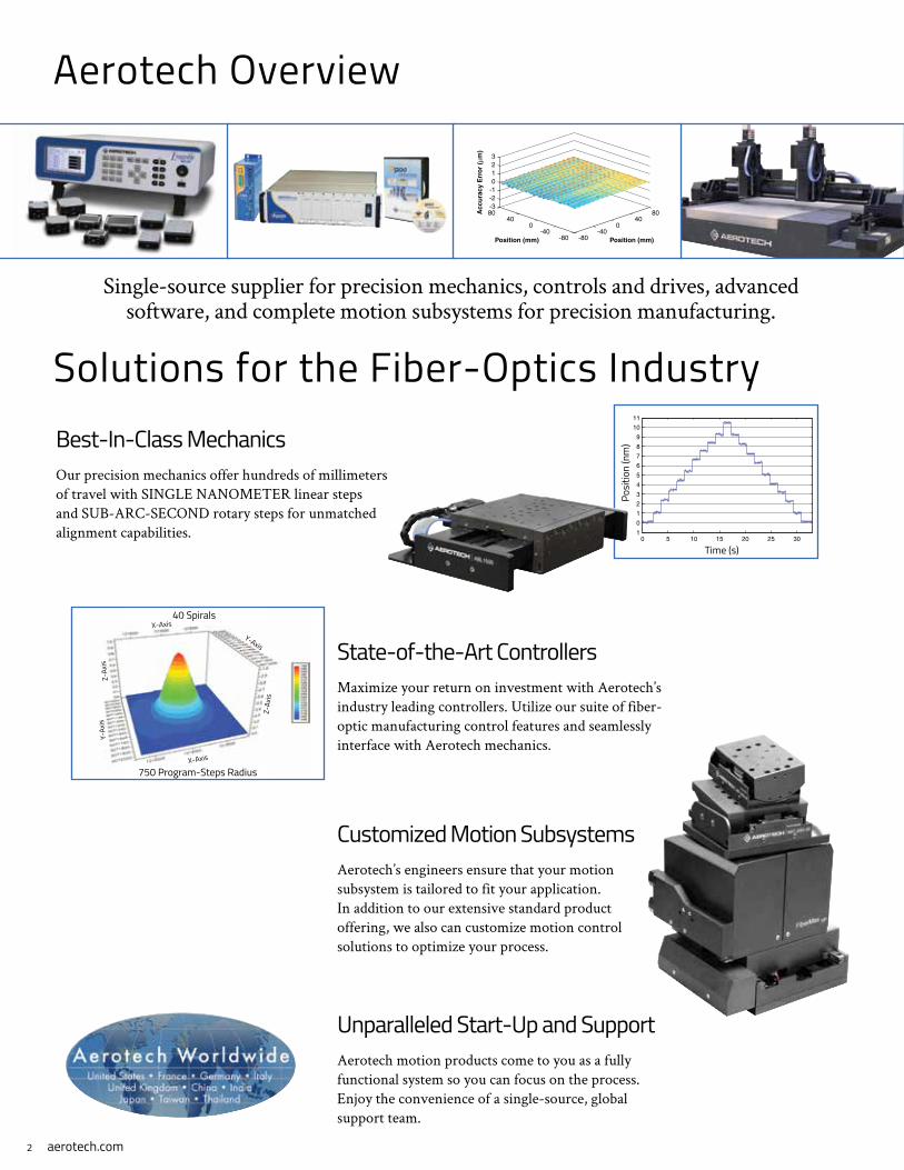
Aerotech Overview
Single-source supplier for precision mechanics, controls and drives, advanced software, and complete motion subsystems for precision manufacturing.
-80-40
040
80
-80-40
040
80-3-2-10123
Position (mm)
Position (mm)
Acc
ura
cy E
rro
r (µ
m)
Solutions for the Fiber-Optics Industry
0 5 10 15 20 25 301
0
1
2
3
4
5
6
7
8
9
10
11
Time (s)
Pos
ition
(nm
)
Best-In-Class MechanicsOur precision mechanics offer hundreds of millimeters of travel with SINGLE NANOMETER linear steps and SUB-ARC-SECOND rotary steps for unmatched alignment capabilities.
State-of-the-Art ControllersMaximize your return on investment with Aerotech’s industry leading controllers. Utilize our suite of fiber-optic manufacturing control features and seamlessly interface with Aerotech mechanics.
Unparalleled Start-Up and SupportAerotech motion products come to you as a fully functional system so you can focus on the process. Enjoy the convenience of a single-source, global support team.
Customized Motion SubsystemsAerotech’s engineers ensure that your motion subsystem is tailored to fit your application. In addition to our extensive standard product offering, we also can customize motion control solutions to optimize your process.
Posi
tion
(nm
)
Time (s)
750 Program-Steps Radius
40 SpiralsX-Axis
X-Axis
Y-Axis
Y-Ax
isZ-
Axis
Z-Ax
is
aerotech.com 3
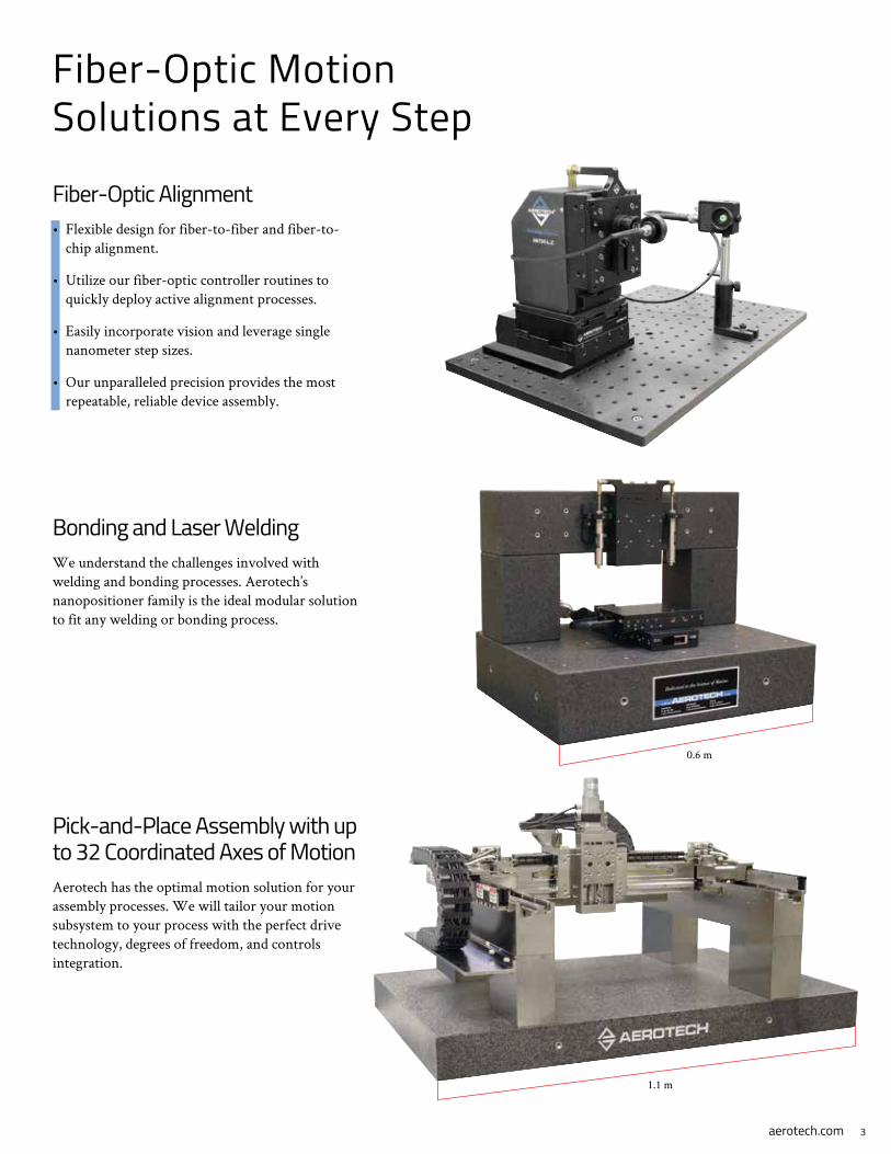
Fiber-Optic Motion Solutions at Every Step
Fiber-Optic Alignment• Flexible design for fiber-to-fiber and fiber-to-
chip alignment.
• Utilize our fiber-optic controller routines to quickly deploy active alignment processes.
• Easily incorporate vision and leverage single nanometer step sizes.
• Our unparalleled precision provides the most repeatable, reliable device assembly.
Bonding and Laser WeldingWe understand the challenges involved with welding and bonding processes. Aerotech’s nanopositioner family is the ideal modular solution to fit any welding or bonding process.
Pick-and-Place Assembly with up to 32 Coordinated Axes of MotionAerotech has the optimal motion solution for your assembly processes. We will tailor your motion subsystem to your process with the perfect drive technology, degrees of freedom, and controls integration.
1.1 m
0.6 m
aerotech.com4
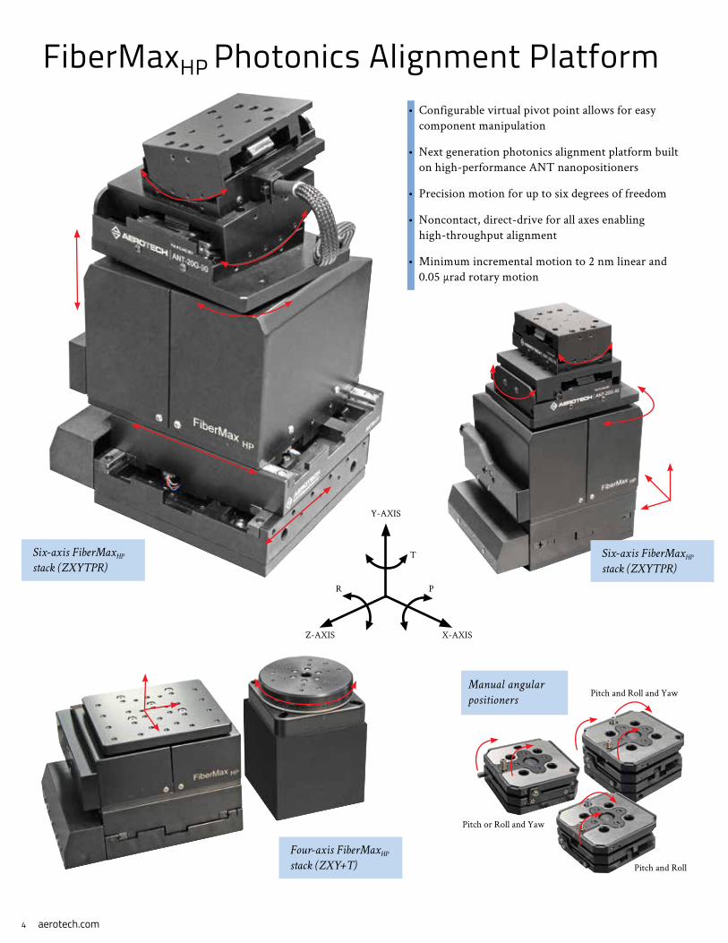
FiberMaxHP Photonics Alignment Platform• Configurable virtual pivot point allows for easy
component manipulation
• Next generation photonics alignment platform built on high-performance ANT nanopositioners
• Precision motion for up to six degrees of freedom
• Noncontact, direct-drive for all axes enabling high-throughput alignment
• Minimum incremental motion to 2 nm linear and 0.05 μrad rotary motion
Six-axis FiberMaxHP
stack (ZXYTPR)
Six-axis FiberMaxHP
stack (ZXYTPR)
Four-axis FiberMaxHP
stack (ZXY+T)
Manual angular
positioners
Pitch and Roll and Yaw
Pitch or Roll and Yaw
Pitch and Roll
Y-AXIS
X-AXISZ-AXIS
R
T
P
aerotech.com 5
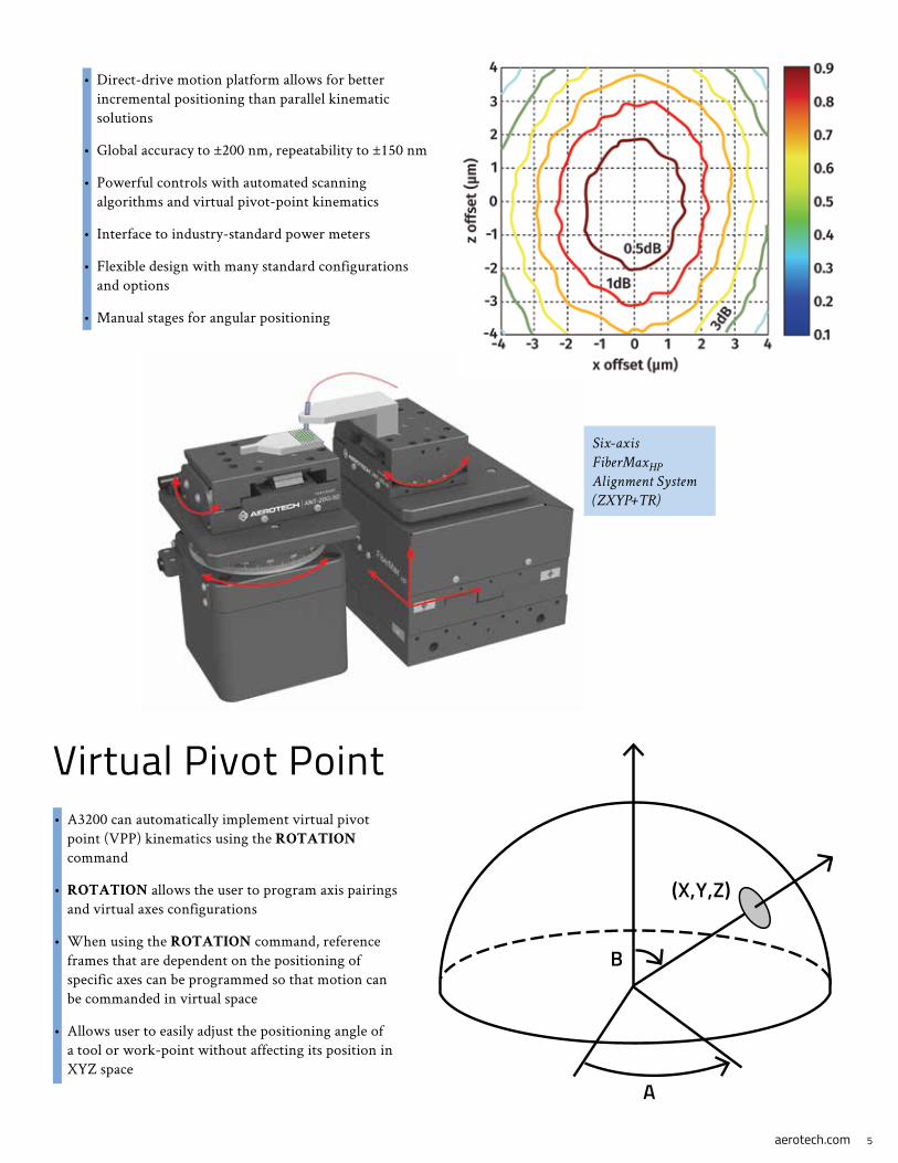
• Direct-drive motion platform allows for better incremental positioning than parallel kinematic solutions
• Global accuracy to ±200 nm, repeatability to ±150 nm
• Powerful controls with automated scanning algorithms and virtual pivot-point kinematics
• Interface to industry-standard power meters
• Flexible design with many standard configurations and options
• Manual stages for angular positioning
Six-axis
FiberMaxHP
Alignment System
(ZXYP+TR)
Virtual Pivot Point• A3200 can automatically implement virtual pivot
point (VPP) kinematics using the ROTATION command
• ROTATION allows the user to program axis pairings and virtual axes configurations
• When using the ROTATION command, reference frames that are dependent on the positioning of specific axes can be programmed so that motion can be commanded in virtual space
• Allows user to easily adjust the positioning angle of a tool or work-point without affecting its position in XYZ space
(X,Y,Z)
B
A

aerotech.com6
Three-axis FA130 e
Fiber Alignment Systems• Three- to six-axis fiber and photonics alignment
• Raster, spiral, or power-peaking algorithms
• 1 nm resolution linear motion
• Turnkey drive and control electronics
• Noncontact direct-drive linear and rotary axes
• Interface to industry-standard power meters
• Crossed-roller mechanical or air-bearing solutions
Aerotech’s FAe series high-performance photonics aligning systems incorporate best-in-class direct-drive and state-of-the-art axis control technology. Their modular design permits the selection of the number of axes, the distance to be travelled, and the amount of payload, all at high-speed, resolution, and accuracy.
Three-axis FA95e
Four-axis FA95e
140 mm
280 mm
The three-axis air-bearing
FiberGlide 3D offers
25, 50, 100, and
150 mm travels
Six-axis
FA130e fiber
alignment
system

aerotech.com 7
PlanarHD
600-600
with weldment and
integrated electronics
Direct-Writing of Waveguides
ABL2000 offers up to
1.2 m travel
Fiber Bragg Grating Solutions
• Linear encoder with optional laser interferometer feedback
• Fully preloaded air-bearing with travels up to 1200 mm
• Excellent pitch, roll, and yaw characteristics and unsurpassed velocity control provide the precise positioning required to ensure wavelength filtering consistency
• Complete noncontact design
• Ultra-precise velocity control
Aerotech’s ABL2000 air-bearing linear stage is specifically optimized for the manufacture of fiber Bragg gratings. A flexible workspace allows the system to be optimized for the unique needs of each manufacturer.
Position Synchronized Output• Aerotech’s Position Synchronized Output (PSO) function triggers the laser in real time as a function of the encoder position, further enhancing the accuracy of the Bragg grating.
• Multiple operation modes allow the user to easily configure laser firing windows and number of laser pulses, simplifying process development.
PlanarHD
600-600 offers
<1 µm 2D accuracy• Maximize throughput with 2 m/s scan velocity and 5 g acceleration
• <1 micron 2D accuracy capable
• Faster turnaround and minimized settling times
• Active yaw control
• Travel to 1.2 m x 1.2 m
Waveguides are structures that guide optical, electromagnetic, or sound waves. Manufacturing of waveguides often involves using a laser to micromachine the surface and bulk of transparent materials. Since absorption of the laser energy is often nonlinear, structural changes can be localized in the bulk of the material, enabling the creation of 3D microstructures. These 3D structures permit fabrication of a wide range of passive and active optical devices for the telecommunications industry. Aerotech’s motion platforms are ideally suited to provide exceptional 2D accuracy and minimal following error while processing at high speeds to reduce cycle time.
aerotech.com8
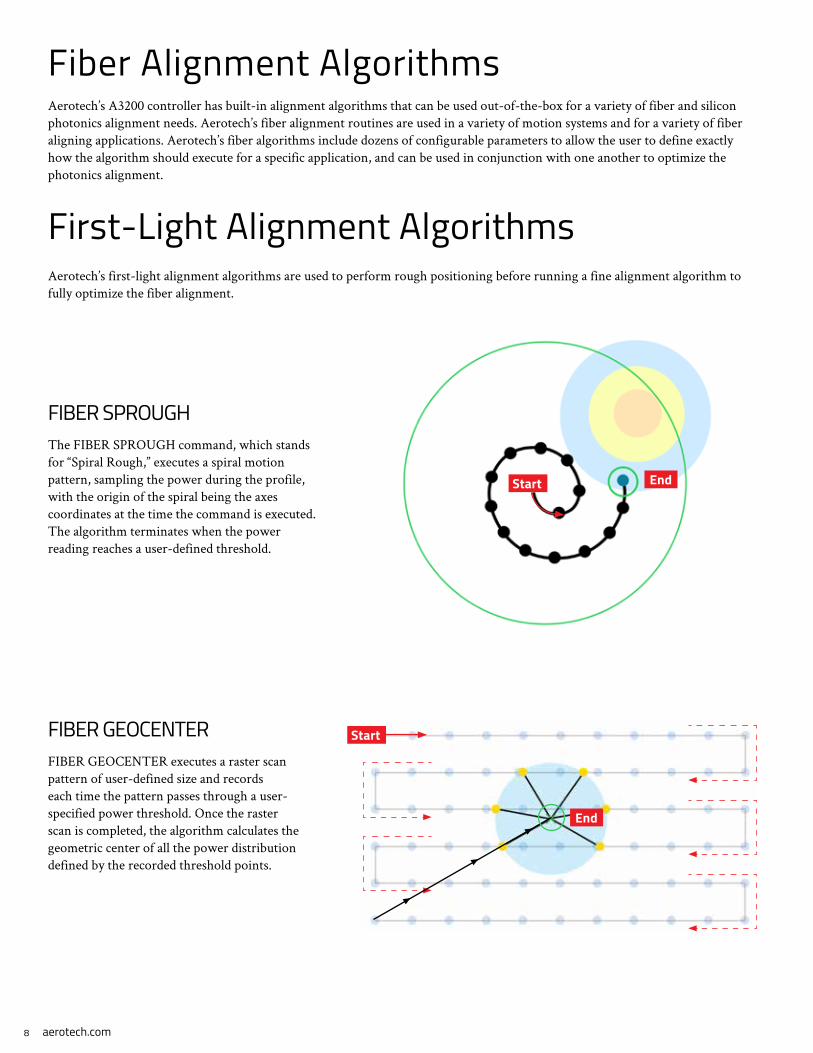
Fiber Alignment AlgorithmsAerotech’s A3200 controller has built-in alignment algorithms that can be used out-of-the-box for a variety of fiber and silicon photonics alignment needs. Aerotech’s fiber alignment routines are used in a variety of motion systems and for a variety of fiber aligning applications. Aerotech’s fiber algorithms include dozens of configurable parameters to allow the user to define exactly how the algorithm should execute for a specific application, and can be used in conjunction with one another to optimize the photonics alignment.
First-Light Alignment AlgorithmsAerotech’s first-light alignment algorithms are used to perform rough positioning before running a fine alignment algorithm to fully optimize the fiber alignment.
FIBER SPROUGHThe FIBER SPROUGH command, which stands for “Spiral Rough,” executes a spiral motion pattern, sampling the power during the profile, with the origin of the spiral being the axes coordinates at the time the command is executed. The algorithm terminates when the power reading reaches a user-defined threshold.
FIBER GEOCENTERFIBER GEOCENTER executes a raster scan pattern of user-defined size and records each time the pattern passes through a user-specified power threshold. Once the raster scan is completed, the algorithm calculates the geometric center of all the power distribution defined by the recorded threshold points.
Start End
Start
End

aerotech.com 9
Power Optimization Alignment AlgorithmsAerotech’s power optimization alignment algorithms are designed to fully optimize a fiber alignment to the maximum power position. Some of these require first light before they can operate, while others do not need first light.
FIBER SPFINEThe FIBER SPFINE algorithm works in a very similar way to the FIBER SPROUGH algorithm, except that it includes a maximum radius parameter instead of a power threshold parameter. The algorithm terminates when this radius is reached, and then the axes return to the point of the highest power reading.
FIBER FASTALIGN (requires first light)The FIBER FASTALIGN command uses an iterative process to explore an area and locate the optimized power location. FASTALIGN can be configured to use anywhere between two and six axes, and finds a point where the power reading exceeds a user-defined threshold.
FIBER CENTROID (requires first light)The FIBER CENTROID algorithm is a fiber alignment method that is particularly useful when the power peak is a plateau or has multiple peaks. FIBER CENTROID will move to the edges of a power peak and then use this data to identify the center of the power peak.
FIBER HILLCLIMBThe FIBER HILLCLIMB routine is used to search in a positive or negative direction along one axis at a time for a local power peak. If the peak is not identified in the first direction, the direction is reversed and the rest of the axis is explored. Once a peak is found, the algorithm returns to this position.
Start
End
Start
End
Start
End

aerotech.com10
The ANT95-L series offers 25,
50, 75, and 100 mm travels
The ANT95-XY series offers
25 x 25 mm or 50 x 50 mm travels
The ANT130-XY series offers 60 x 60,
110 x 110, or 160 x 160 mm travels
The ANT130-L series offers 35,
60, 110, and 160 mm travels
ANT-Series Nanopositioners• Noncontact, non-cogging,
frictionless direct-drive motion
• 1 nm resolution
• 250 nm accuracy
• 75 nm repeatability
• Sub-nanometer in-position stability
• High dynamic performance
• Low profile
Single-Axis LinearANT95-L Single-Axis Linear Stage ANT130-L Single-Axis Linear Stage
Integrated XYANT95-XY Dual-Axis Linear Stage ANT130-XY Dual-Axis Linear Stage
95 mm 130 mm
130 mm95 mm
aerotech.com 11
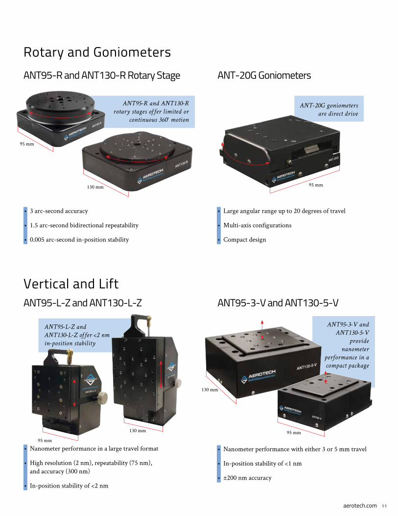
ANT95-R and ANT130-R
rotary stages offer limited or
continuous 360° motion
ANT-20G goniometers
are direct drive
Rotary and Goniometers
• 3 arc-second accuracy
• 1.5 arc-second bidirectional repeatability
• 0.005 arc-second in-position stability
ANT95-R and ANT130-R Rotary Stage ANT-20G Goniometers
• Large angular range up to 20 degrees of travel
• Multi-axis configurations
• Compact design
Vertical and LiftANT95-L-Z and ANT130-L-Z
• Nanometer performance in a large travel format
• High resolution (2 nm), repeatability (75 nm), and accuracy (300 nm)
• In-position stability of <2 nm
ANT95-L-Z and
ANT130-L-Z offer <2 nm
in-position stability
ANT95-3-V and ANT130-5-V
ANT95-3-V and
ANT130-5-V
provide
nanometer
performance in a
compact package
• Nanometer performance with either 3 or 5 mm travel
• In-position stability of <1 nm
• ±200 nm accuracy
95 mm
130 mm 95 mm
95 mm
130 mm
130 mm
95 mm

aerotech.com12
Q-Series Piezo NanopositionersAerotech’s Q-series piezo stages offer sub-nanometer positioning resolution and nanometer-level accuracy (linearity). Open- and closed-loop feedback are available on all Q-series nanopositioners. The closed-loop capacitive sensor feedback allows for direct measurement of the positioning carriage. Also, the Q-series piezos can be effortlessly integrated into a system with servo axes to allow integrated coarse and fine motion control. Vacuum preparation is available.
QNP-L, QNP-XY, and QNP-Z Medium Travel Linear Stages• Travels include 100 µm, 250 µm, and 500 µm
• Linearity is to 0.007% of travel
• High stiffness permits the devices to achieve high throughput
• Large resonant frequencies, up to 1300 Hz for the 100 µm QNP-L, allow for fast closed-loop response
• Excellent geometric flexure performance allows for nanometer-level straightness/flatness
• Load capacity up to 1 kg
• Stages designed to easily mount together for various configurations
QNPHD Series• Closed-loop travels from 10 μm to 40 μm
• Direct-drive actuation enables fast response times and higher-throughput processes
• High-precision, frictionless flexure guidance
• Long device lifetime
• Superior positioning resolution (0.03 nm) and linearity (0.02%) with direct-metrology capacitive sensor option
• Open-loop and vacuum versions
QFOCUS QF-46 Single-Axis Piezo Microscope Objective• Travels from 100 µm to 300 µm
• High-stiffness and dynamics resulting in outstanding step-and-settle and scanning performance
• Mounting flexibility with a variety of threaded adapters or mounting holes for custom mounting arrangements

13aerotech.com
Q-Series Piezo ControllersThe Q-series piezo controllers offer exceptional flexibility and performance. QLAB can control 1-4 axes of piezo nanopositioning stages in open or closed-loop operation. The QDe allows the piezo axes to be networked effortlessly with servo axes using Aerotech’s powerful controller platform. This integrated programming environment and the ability to synchronize piezo and servo motion significantly reduces system and programming complexity. Additionally, advanced features are available for both piezo and servo axes, configurable with a simple and easy-to-use interface.
QLAB Controller• Controls up to 4 axes
• -30 to +150 V semi-bipolar output
• 20-bit capacitive sensors for high resolution
• Ethernet and USB 2.0 communication
• Intuitive design and touch-screen panel for ease of use
Ndrive QLe• Real-time distributed control architecture allows synchronized motion
control on up to 32 axes of piezo and/or servomotor stages
• Single- or multi-axis Position Synchronized Output (PSO) for real-time triggering of events
• Thermally-stable feedback circuit design option
• Advanced control features such as Learning Control, Harmonic Cancellation, and Command Shaping improve tracking error and overall process throughput
Advanced Control Features
Position Synchronized Output (PSO)• Prompt a tool to fire based
on actual position feedback
• Uses the capacitive probe for direct measurement of the actual carriage position
Learning Control• Allows for repeating move
sequences to be learned and optimized
• Reduces following error
• Increases dynamic accuracy
• Increases throughput and production rates
Harmonic Cancellation• Reduces position error in
the presence of periodic disturbances
• Adapts to the magnitude and frequency of the error source
Command Shaping• Reduces vibration in point-
to-point moves
• Allows for faster settling time at the work point
14 aerotech.com
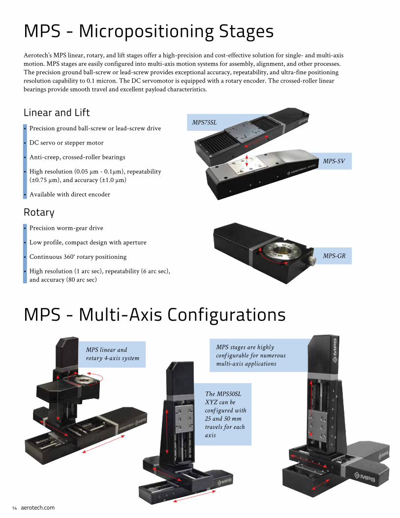
MPS75SL
MPS-SV
MPS-GR
MPS - Micropositioning StagesAerotech’s MPS linear, rotary, and lift stages offer a high-precision and cost-effective solution for single- and multi-axis motion. MPS stages are easily configured into multi-axis motion systems for assembly, alignment, and other processes. The precision ground ball-screw or lead-screw provides exceptional accuracy, repeatability, and ultra-fine positioning resolution capability to 0.1 micron. The DC servomotor is equipped with a rotary encoder. The crossed-roller linear bearings provide smooth travel and excellent payload characteristics.
Linear and Lift• Precision ground ball-screw or lead-screw drive
• DC servo or stepper motor
• Anti-creep, crossed-roller bearings
• High resolution (0.05 µm - 0.1µm), repeatability (±0.75 µm), and accuracy (±1.0 µm)
• Available with direct encoder
Rotary• Precision worm-gear drive
• Low profile, compact design with aperture
• Continuous 360° rotary positioning
• High resolution (1 arc sec), repeatability (6 arc sec), and accuracy (80 arc sec)
MPS - Multi-Axis ConfigurationsMPS linear and
rotary 4-axis system
The MPS50SL
XYZ can be
configured with
25 and 50 mm
travels for each
axis
MPS stages are highly
configurable for numerous
multi-axis applications
15aerotech.com
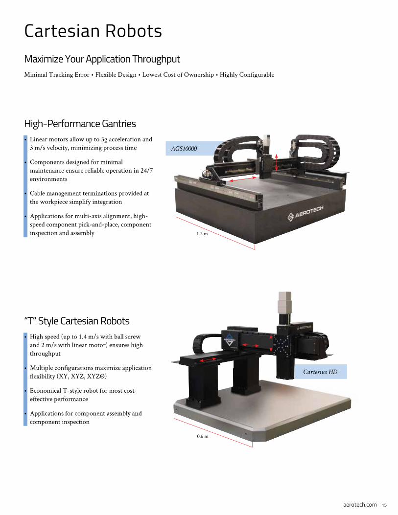
Cartesian RobotsMaximize Your Application ThroughputMinimal Tracking Error • Flexible Design • Lowest Cost of Ownership • Highly Configurable
High-Performance Gantries• Linear motors allow up to 3g acceleration and
3 m/s velocity, minimizing process time
• Components designed for minimal maintenance ensure reliable operation in 24/7 environments
• Cable management terminations provided at the workpiece simplify integration
• Applications for multi-axis alignment, high-speed component pick-and-place, component inspection and assembly
“T” Style Cartesian Robots• High speed (up to 1.4 m/s with ball screw
and 2 m/s with linear motor) ensures high throughput
• Multiple configurations maximize application flexibility (XY, XYZ, XYZΘ)
• Economical T-style robot for most cost-effective performance
• Applications for component assembly and component inspection
AGS10000
Cartesius HD
1.2 m
0.6 m

aerotech.com
Aerotech WorldwideUnited States • France • Germany • Italy • United Kingdom
China • India • Japan • Taiwan • Thailand
CA0416A