precision water distillers owners’ guide · pdf fileprecision water distillers...
TRANSCRIPT

Part No. 097126A
Series: 0015
Printed in Canada
PWS 8M PWS 8-MST STORAGE TANK
PWS, 8M COVER PAGE
Precision Water Distillers Owners’ Guide
Model: 8-M Model: 8-MST Part No. 500000 Part No. 500001 Series: 0015 Series: 0014
Manufactured By: Precision Design & Manufacturing Inc. 9024-100 Street Westlock, AB, Canada T7P 2L4 http://www.precisioncanada.com e-mail: [email protected] Phone: (780) 349 4933 FAX: (780) 349 4957
Please read this Owners’ Guide completely before installing or
operating your Precision Water Distiller.
Specifications are subject to change without notice.

2
This page left intentionally blank.

3
TABLE OF CONTENTS .............................................................................................................................. 3
INTRODUCTION ........................................................................................................................................ 4
RECORDS ..................................................................................................................................................... 5
PRECISION WATER SYSTEMS WATER DISTILLER WARRANTY ................................................ 6
IMPORTANT SAFETY PRECAUTIONS .................................................................................................. 7
PRECISION WATER SYSTEMS WATER DISTILLER OWNERS' SUMMARY ............................... 8
WATER DISTILLER AND OPTIONAL STORAGE TANK FEATURES ............................................ 9
10 FACTORS THAT WILL AFFECT YOU WATER DISTILLER PRODUCTION ......................... 10
UNDERSTANDING HOW PURE WATER IS PRODUCED ................................................................. 12
FINDING A GOOD INSTALLATION LOCATION ............................................................................... 13
UNPACKING YOUR WATER DISTILLER ........................................................................................... 13
WATER DISTILLER INSTALLATION TOOLS ................................................................................... 15
WATER DISTILLER LEG INSTALLATION ........................................................................................ 16
OPTIONAL STORAGE TANK ASSEMBLY .......................................................................................... 16
OPTIONAL STORAGE TANK TO DISTILLER HEAD ASSEMBLY ................................................ 18
IMPURITIES DRAIN TUBE INSTALLATION...................................................................................... 19
BOILING TANK LID INSTALLATION ................................................................................................. 20
OPTIONAL STORAGE TANK LID REMOVAL AND INSTALLATION .......................................... 20
OPERATION ............................................................................................................................................... 21
CONTROLS - POWER, FAN, AND OVERHEAT RESET ..................................................................................... 21 BEFORE INITIAL WATER DISTILLER OPERATION ......................................................................................... 23 NORMAL OPERATION .................................................................................................................................. 23
MAINTENANCE AND CLEANING ........................................................................................................ 25
REGULAR INSPECTION AND CLEANING OF BOILING TANK .......................................................................... 25 CLEANING THE BOILING TANK USING CLEANER DESCALER ....................................................................... 26 REPLACING CHARCOAL IN POST CHARCOAL FILTER CANISTER (USED WITH 8-M) ..................................... 27 REPLACING CHARCOAL IN CHARCOAL FILTER CANISTER (USED WITH 8-MST) ......................................... 28 STERILIZATION............................................................................................................................................ 29
Liquid Sterilization of Optional Storage Tank ........................................................................................ 29 Steam Sterilization of Water Distiller Head ............................................................................................ 30 Steam Sterilization of Water Distiller Head, Filter Canister and Optional Storage Tank ...................... 32 Maintenance Schedule Table .................................................................................................................. 33 Owner Maintenance Record Table.......................................................................................................... 33
TROUBLESHOOTING .............................................................................................................................. 34
ADDITIONAL OPTIONS .......................................................................................................................... 36
SPECIFICATIONS AND TECHNICAL INFORMATION .................................................................... 37
WIRING LIST AND SCHEMATICS .................................................................................................................. 38
INDEX .......................................................................................................................................................... 40
WARRANTY REGISTRATION CARD ................................................................................................... 41
Table of Contents

4
Introduction
Congratulations on the purchase of the most advanced water distiller in the industry! When installed and maintained properly, your Precision Water Systems water distiller will provide years of safe, trouble free service. It is important to observe and follow the safety and maintenance instructions carefully. If you have any questions or concerns regarding installation or operation of your water distiller, please contact your dealer. All 120 VAC Precision Water Systems Water Distillers are certified to cCSAus Classes 2831-02 and 2831-82 under the Canadian and American Electrical Code. All Water distillers are factory tested with a high voltage ‘Dielectric Strength Test’ and ground fault test prior to shipping. Precision Water Systems Water Distillers have been tested by EnviroTest Laboratories which found the water distillation units to be very effective water treatment systems capable of removing both harmful pathogens and toxic chemicals from water. In their study all pathogens were eliminated and none were found in the distilled water. The water distillation system also effectively removed all of the soluble inorganic chemicals tested. Removal efficiencies of 99% or greater were achieved for almost every chemical tested. All Precision Water Systems Water Distillers are operated and tested at the factory and have produced distilled water to make sure all components are functioning properly. All water distillers are wiped clean before shipping, but there may be a water ring inside the boiling tank. There may also be an off-colour line at the seams of the storage and boiler tank. This is caused by the TIG welding process used during manufacturing. This is normal and is not a sign of a problem. Follow all the Before Initial Water Distiller Operation procedures and you will have pure water in no time. Your Precision Water Systems Water Distiller must be installed according to any Local, State or Provincial Regulations.

5
Records
Please record all of the important information below to assist you and the service center in case there is any service work required in the future. All of the information is required to properly identify your water distiller and optional storage tank and will make servicing much easier. The information is located on the serial plate on the side of the water distiller head and optional storage tank. The Serial Plate Location Diagram below shows sample serial plates.
Distiller Head Optional Storage Tank
Serial Plate Location Diagram
Distiller Head:
Model: PWS 8-M
Series: eg: 0001
Serial Number: eg: 0123012
Optional Storage Tank:
Model: PWS 8-MST
Series: eg: 0001
Serial Number: eg: 0123012
Date of Purchase: ___________________________________________________
SERIAL PLATE LOCATION DIAGRAM - 8GPD SERIAL PLATE LOCATION DIAGRAM - MST

6
Precision Water Systems Water Distiller Warranty
- The warranty for your Precision Water Systems Water Distiller covers defects in materials for two (2) years on all parts and
labour to the original purchaser. - Stainless Steel parts are covered by a 15 year
pro rated warranty. This covers all stainless steel parts such as the boiling and optional storage tank. With this warranty it is the responsibility of the distiller owner to properly maintain the distiller. If there is any misuse or abuse the warranty will be void.
- Precision Water Systems does not warrant any
transportation charges incurred to complete the repair. The distiller owner is responsible
for all shipping charges to and from the service center.
- Warranty is void if the distiller is found to
have been consumer damaged or misused, caused by acts of God, unauthorized alteration, repair or vandalism.

7
Important Safety Precautions
When using electrical appliances, basic safety precautions should always be followed including the following:
1. Read all instructions. 2. Do not touch hot surfaces. Use handles or knobs.
3. To protect against electrical shock do not immerse cords or plugs in water or other liquid.
4. Close supervision is necessary when any appliance is used near children.
5. Do not allow children to operate this appliance.
6. Unplug from outlet when not is use and before cleaning. Allow to cool before putting on or taking off parts.
7. Do not operate any appliance with a damaged cord or plug or after the appliance malfunctions or has been damaged in any manner. Return appliance to the nearest service facility for examination, repair or adjustment.
8. The use of accessory attachments not recommended by the appliance manufacturer may cause injuries.
9. Do not use outdoors.
10. Do not let cord hang over edge of table counter, or touch hot surfaces.
11. Do not place on or near a hot gas or electric burner, or in a heated oven.
12. Extreme caution must be used when moving an appliance containing hot water.
13. Always attach plug to appliance first, then plug cord into the wall outlet. To disconnect, turn any controls to “off”, then remove plug from wall outlet.
14. This appliance is intended for household use.
15. Save these instructions.
Additional Safety Recommendations 1. Always unplug appliance before servicing.
2. Do not use extension cords with appliance.
3. Ensure there is adequate air space around the appliance to allow the heat from the appliance to be removed and supply adequate fresh air for cooling.

8
Precision Water Systems Water Distiller Owners’ Summary
The following is a summary of the information contained in this Owners’ Guide and required to install and operate your Water
Distiller
1) Find a good location for installing your Water Distiller – See Finding a Good Installation Location.
2) Unpack the water distiller and parts - See Unpacking Your Water Distiller.
3) Assemble the Water Distiller – See Water Distiller Leg Installation Optional Storage Tank Assembly Impurities Drain Tube Installation Boiling Tank Lid Installation
4) Steam sterilize boiling tank – See Steam Sterilization of Water Distiller Head in the Maintenance and Cleaning section.
5) Load Charcoal Filter Canister – See Replacing Charcoal in Post Charcoal Filter Canister (Used with 8-M without Optional Storage Tank) in the Maintenance and Cleaning section.
6) Follow procedure in Normal Operation section.
7) Enjoy pure, distilled water!

9
8-M Distiller Features
8-MST Optional Storage Tank Features
Water Distiller and Optional Storage Tank Features
DISTILLER FEATURES DIAGRAM, PWS 8M
CONDENSING COIL SHIPPING STRAP
(REMOVE BEFORE USE)
FAN SWITCH
POWER SWITCH
OVERHEAT RESET SWITCH
BOILING TANK LID
GAS RELEASE VENT (HIDDEN)
CONDENSING COIL (INSIDE)
BOILING TANK
(INSIDE)
LEG
DRAIN VALVEPOST CHARCOAL
FILTER
FILTER CAP
FEED TUBE
LID KNOB
MANUAL STANDARD TANK FEATURES
SIGHT GAUGE AND
DRAIN VALVE
STORAGE TANK
CHARCOAL FILTER
CANISTER BODY
LEG
STORAGE TANK LID
10
1. Water Volume Measurement
a) How are you measuring your water? The most accurate is by weight. 1 litre of pure water = 1 kg = 1000 g = 2.2046 lbs
b) Water distillers are rated in US gallons, NOT Imperial Gallons. 1 US Gallon = 3.785 litres = 3.785 kg = 8.344 lbs = 0.833 Imp. Gallons
c) Most distilled water holding tanks do not completely drain from the tap. Ensure this volume of water is included in your calculation by completely draining the tank or starting your production check with this volume pre- filled.
2. Line Voltage
The line voltage at the outlet where the distiller is connected should be checked with a voltmeter. Line voltage is often much less than expected, especially in rural areas. Line voltage will also usually drop off dramatically when the daily commercial load hits the grid from approximately 8 am to 5 pm (often when the distiller owner is not home and unable to check the line voltage). Line voltage lower than the distiller rated voltage (on the serial plate) will drastically lower the water production.
3. Fill Water Temperature The water used to fill the machine may affect the water production. Cooler fill water will take more time/energy to heat to the boiling point than hot water.
4. Ambient Air Temperature
Water distillers with cooling fans must have sufficient ventilation so that the boiled steam can be cooled and condensed into distilled water. Restriction of air flow (such as a closed cupboard) will result in a hot ambient air build up which will not allow all of the steam to condense into distilled water and some water production may escape as steam into the atmosphere through the charcoal filter or volatile gas release vent. This steam loss can also occur in hot summer periods or very warm climates.
10 Factors That Will Affect Your Water Distiller Production

11
5. Heating Element and Boiler Cleanliness
As the water distiller removes impurities some of the impurities may cling to the boiler tank and the heating element. Any of this scale may build up around the heating element and actually insulate it, which will drastically decrease the thermal efficiency of the heating element and require more time/energy to boil water, which will decrease the water production.
6. Altitude
The water distiller is rated at the altitude of the manufacturer, which is approximately 675 m (2214 ft) above sea level. Locations lower than this (closer to sea level) will have reduced water production due to the higher boiling point of water at higher atmospheric pressures at lower altitudes.
7. Operating Time, Warm-up Period & Suitable Storage
When checking the water distiller production, the start time should be when the first few drops of water have entered the charcoal filter canister. Do not start timing when the distiller turns on as it takes a few minutes for the heating element, boiler tank and water to heat up. The distiller production rating does NOT account for this time, but rather the continuous production after the distiller is up to temperature. Ensure when checking production that you have suitable water storage for holding the amount of water that will be produced.
8. Manual Fill Boiling Tank Fill Level When checking the water distillation production on manual fill water distillers the amount of water initially poured into the boiling tank will affect the production. Water should be filled to the water level pin so that once the water is hot the maximum amount of water can be distilled without having to heat up and refill. Under-filling the boiler will decrease the amount of water distilled. Again, the warm-up time should not be included in the production rate
9. Boiling Tank Heating Element Once all other factors have been eliminated or checked, have an authorized service center check that the proper heating element has been installed in your distiller. Always replace heating elements with the manufacturers supplied heating elements. Other elements are available from hardware stores, home repair centers etc. and look like the same element but they are almost always not the same. Even if the voltage and wattage are the same, they usually have different wattage densities and most likely different element sheath materials, which will result in premature heater burnout in continuous water distillation of raw water. These heating elements will also likely affect you water distillation capacity.
10. Combination of the above Factors. Often a reduced water distiller’s production is a combination of many or all of the above factors. To ensure maximum production from your water distiller, keep your water distiller clean and operate it in a well-ventilated area and use room temperature feed water where possible.

12
Your water distiller operates the same as Nature’s hydrological cycle. See the Hydrological Cycle Diagram below. Nature uses the heat of the sun to vaporize surface water and draw it into the atmosphere leaving the impurities behind. As the vapour cools it condenses and returns back to the earth as rain or snow. When rain or snow falls it passes through smog, dust and many other types of contaminants. These contaminants can be picked up by the falling rain or snow. Additional contamination of water can occur when it moves through the ground.
Hydrological Cycle Diagram
Water Distillers complete their own hydrological cycle. The advantage of a water distiller over Nature is that the water is produced in a closed environment free of pollution and contaminants.
Your water distiller uses the boiling tank to heat the feed water to create steam. The steam rises from the boiling tank leaving almost all of the impurities behind. The steam enters the condensing coil and is cooled by the fan. As the steam cools it condenses into pure distilled water and is stored in a water bottle or optional stainless steel storage tank. The charcoal filter (between the condensing coil and storage container) and the volatile gas vent remove any contaminants that boil at lower temperatures than the boiling point of water. The impurities from the process remain in the boiling tank and are drained to a suitable drain.
CONDENSATION
EVAPORATION
SMOG, DUST, ETC.
ROCK DEEP PERCOLATION
GROUND WATER
SURFACE WATER
HYDROLOGICAL CYCLE DIAGRAM
PRECIPITATION
Understanding How Pure Water is Produced

13
Before installing your water distiller it is important to find a good location.
Following the points listed below will provide the best location for your water distiller:
1. The water distiller must be plugged directly into a dedicated 120VAC, 15 Amp wall outlet.
2. The water distiller requires sufficient airflow around it to operate. The air is used to cool the water distiller condensing coil. Locate the water distiller in an area that will provide enough room for good air flow. Do not place the water distiller in an enclosed area like a closet.
3. Locate the water distiller where a pail, suitable container or drain can be used for the impurities drain.
4. When unpacking the water distiller and options note the sizes and consider this when picking an installation location.
5. Locate the water distiller away from a bedroom or other area where the noise of the water distiller may be undesirable.
6. Locate the water distiller in an area that is clean and free of dust so the cooling coils remain clean when the fan is drawing fresh air.
Your Water distiller has been shipped in one box. The Water Distiller Box Components Diagram shown as follows displays all of the parts that will be in the water distiller box.
Water Distiller Box Components Diagram
Water Distiller Box Check List Check List
(A) 1 – Water Distiller Head (B) 1 -- Parts Bag
(Water Distiller Parts Bag Components Diagrams shown as follows)
(B) 1x(A) 1x
UNPACKING DISTILLER BOX DIAGRAM
Unpacking Your Water Distiller
Finding a Good Installation Location

14
Water Distiller Parts Bag Components Diagram
Water Distiller Parts Bag Check List Check List Part No.
(A) 500409 1 – Post Filter (B) 080115 1 – Sample Descaler/Cleaner (C) 080116 1 – Sample Coconut Charcoal (D) 500212 1 – Tube, Manual Drain, Stainless Steel (E) 054009 4 – Black Plastic Legs (F) 500184 1 – Boiling Tank Lid (G) 052000 1 – 2’ Clear Sterilization Drip Tube (H) 018004 4 – ½” x 5/16” SS Washers
1. Remove all loose pieces from the water distiller box and save all packaging until all the parts are identified and located.
2. Check inside boiler tank and optional storage tank for any parts that may be shipped in that area. If any parts are missing or if you have been given the wrong part, DO NOT return the water distiller unit. Contact your dealer for the required parts. They will be pleased to assist you.
3. Remove all protective plastic from water distiller head, boiling tank lid and optional storage tank and lid.
(C) 1x(B) 1x
(G) 1x (H) 4x(F) 1x
(A) 1x (D) 1x
(E) 4x

15
Shipping Tie Removal Diagram
4. Refer to Shipping Tie Removal Diagram above. Cut/Remove the coil support tie located on the top of the water distiller head. Be careful not to scratch the water distiller when removing. This tie supports the cooling coil during shipping only.
TOOLS REQUIRED: For Water Distiller Installation
(A) 5/8” Open End Wrench
(B) Adjustable Wrench
Water Distiller Installation Tools TOOL REQUIRED FOR DISTILLER INSTALLATION, EAU M
(A) (B)
OR
COIL SUPPORT TIE
WATER DISTILLER HEAD
SHIPPING TIE REMOVAL DIAGRAM

16
1. Refer to the Water Distiller Leg Installation Diagram shown below. Place a ½ x 5/16” stainless steel washer on the threads of each leg and screw the legs into the bottom of the distiller head.
Water Distiller Leg Installation Diagram
Sight Tube Assembly 1. Remove the sight gauge from the parts bag and packaging.
Sight Gauge Installation Diagram
Water Distiller Leg Installation
Optional Storage Tank Assembly
DISTILLER LEGS INSTALL DIAGRAM
BULKHEAD
WASHER
LEG
POWER CORD
SIGHT GAUGE INSTALL DIAGRAM
3/8" JAM NUTSTORAGE TANK
SIGHT GAUGE
VALVE HANDLE
DRAIN VALVE THREADED FAUCET END
GASKET

17
2. Refer to the Sight Gauge Installation Diagram above. Remove the plastic hex jam nut from the threaded body of the valve (leaving water gasket on threads).
3. Remove the storage tank lid by holding down on the lid and turning the black knob counter clockwise approximately five turns. Slide the lid to one side and turn the knob and lid while tilting. This should allow the Tee Bar bracket under the lid to come out of the tank opening. Slide the lid out.
4. Push the gasket tightly up against the valve.
5. Insert the threaded valve end with gasket attached through the hole on the front of the storage tank.
6. While holding the sight gauge with valve in the storage tank hole with one hand, insert your other hand with the plastic hex jam nut through the storage tank lid opening.
7. Place the hex nut onto the threaded end of the valve.
8. Hand tighten the hex nut clockwise onto the valve.
Tightening Sight Gauge Nut Diagram
9. Refer to the Tightening Sight Gauge Nut Diagram above. To fully tighten the nut, turn the valve counter-clockwise1/4 of a turn to the start position and ensure that the jam nut is still hand tight. Holding the jam nut, turn the valve clockwise until upright at the finish position.
10.Make sure the storage tank is free from any dust or material and
replace the storage tank lid.
11.Check for leaks when storage tank begins filling.
NOTE: The sight glass is fragile, do not push on the gauge (push on bottom near threaded area).
SIGHT GAUGE INSTALLATION DIAGRAM

18
1. If you have purchased the optional storage tank, place the Charcoal Canister in the top of Storage Tank.
2. Place lid on storage tank.
3. Refer to the Distiller Head to Optional Storage Tank Assembly Diagram below. Place Distiller head on top of the optional storage tank by placing the legs of the distiller head onto the leg stubs on the optional storage tank.
Distiller Head to Optional Storage Tank Assembly Diagram
Optional Storage Tank to Distiller Head Assembly
CHARCOAL FILTER
CANISTER BODY
DRAIN VALVE
VALVE HANDLE
THREADED FAUCET END
STORAGE TANK TO DISTILLER HEAD ASSEMBLY DIAGRAM
STORAGE TANK
SIGHT GAUGE GASKET
LEG
STORAGE
TANK LID
DISTILLER HEAD
3/8"
JAM NUT

19
1. Refer to the Impurities Drain Tube Installation Diagram shown below. Remove the compression nut and compression sleeve from the Drain Valve.
Impurities Drain Tube Installation Diagram
2. Take the stainless steel manual drain tube from the parts bag. Slip the compression nut and compression sleeve over the manual drain tube.
3. While holding the compression nut and sleeve on the drain tube, push the manual drain tube into the drain valve. Push the compression sleeve into the valve with the nut and thread the nut onto the valve.
4. Position the drain tube away from the distiller and tighten the nut with a 5/8” open end wrench or adjustable wrench. When draining the boiling tank of the water distiller, the manual drain tube should be drained into a suitable container or sewer.
Impurities Drain Tube Installation
DISTILLER HEAD
MANUAL DRAIN VALVE INSTALL DIAGRAM
COMPRESSION SLEEVE
COMPRESSION NUT
MANUAL DRAIN TUBE
DRAIN VALVE
TO SEWER OR
IN A CONTAINER

20
1. Remove any protective plastic coating (white, blue or clear plastic) from the lid.
Boiling Tank Lid Operation Diagram
2. Refer to the Boiling Tank Lid Operation Diagram above. Take the boiling tank lid in your hand. Hold the Tee Bar bracket and turn the Lid Knob counter-clockwise so that there is ½” of space between the Tee Bar bracket and the lid.
3. Tip the lid so that the Tee Bar bracket slips under the rim of the boiling tank opening on one side, and then slide the lid so the Tee Bar bracket slips under the other side of the rim. Center the lid.
4. Turn clockwise to tighten the lid onto the boiling tank. The water level pin inside the boiling tank will prevent the lid from turning while tightening. Practise removing and replacing the lid a few times as the lid will need to be removed each time the water distiller is filled or cleaned.
1. To remove the optional storage tank lid, turn the Lid Knob counter-
clockwise while lifting. Lifting while turning holds the Tee Bar bracket under the lid and allows you to loosen the lid. Continue turning and lifting until there is ½” of space between the Tee Bar bracket and the lid.
2. Tip the lid so that the Tee Bar bracket slips out from under the rim of the
optional storage tank opening on one side, and then slide the lid so the Tee Bar bracket slips out from under the other side of the rim.
3. To Replace the optional storage tank lid, tip the lid so that the Tee Bar
bracket slips under the rim of the boiling tank opening on one side, and then slide the lid so the Tee Bar bracket slips under the other side of the rim. Center the lid.
4. While lifting up on the optional storage tank lid knob, turn clockwise to
tighten the lid onto the optional storage tank. When upward pressure is no longer needed to prevent the lid from turning the lid is tight.
Boiling Tank Lid Installation
Optional Storage Tank Lid Removal and Installation
BOILER LID INSTALL DIAGRAM

21
Controls
(A) (B) (C)
Operation Switches Diagram
Refer to the Operation Switches Diagram above. There are two grey power switches (A&B) and one overheat manual reset switch (C) on the front of the water distiller head that allow you to control all functions of the water distiller
Operation
NOTE: Read all parts of the Owners Guide before operating the water distiller. Follow the Before Initial Water Distiller Operation steps and be sure to complete a Steam Sterilization of the Water Distiller Head, Filter Canister and Optional Storage Tank (if purchased) before distilling water for household use for the first time or after a period of storage or non-use.
OPERATION SWITCHES DIAGRAM
COOLING FAN
INDICATOR LIGHT
HEATING ELEMENT
INDICATOR LIGHT PO
WE
R O
N IN
DIC
AT
OR
LIG
HT
S
ONOFF
22
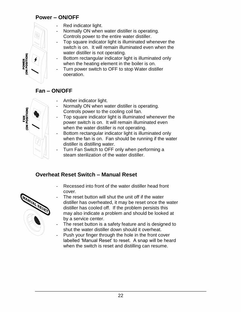
Power – ON/OFF
Fan – ON/OFF
Overheat Reset Switch – Manual Reset
- Red indicator light. - Normally ON when water distiller is operating.
Controls power to the entire water distiller. - Top square indicator light is illuminated whenever the
switch is on. It will remain illuminated even when the water distiller is not operating.
- Bottom rectangular indicator light is illuminated only when the heating element in the boiler is on.
- Turn power switch to OFF to stop Water distiller operation.
- Recessed into front of the water distiller head front cover.
- The reset button will shut the unit off if the water distiller has overheated, it may be reset once the water distiller has cooled off. If the problem persists this may also indicate a problem and should be looked at by a service center.
- The reset button is a safety feature and is designed to shut the water distiller down should it overheat.
- Push your finger through the hole in the front cover labelled ‘Manual Reset’ to reset. A snap will be heard when the switch is reset and distilling can resume.
- Amber indicator light. - Normally ON when water distiller is operating.
Controls power to the cooling coil fan. - Top square indicator light is illuminated whenever the
power switch is on. It will remain illuminated even when the water distiller is not operating.
- Bottom rectangular indicator light is illuminated only when the fan is on. Fan should be running if the water distiller is distilling water.
- Turn Fan Switch to OFF only when performing a steam sterilization of the water distiller.
FAN SWITCH DIAGRAM
(O
N P
OS
IT
IO
N)
FA
N
POWER SWITCH DIAGRAM
PO
WE
R
(O
N P
OS
IT
IO
N)
MANUAL RESET SWITCH DIAGRAM

23
Perform steam sterilization on the water distiller head, filter canister and optional storage tank as described in the Maintenance and Cleaning section.
operly
1. Remove the lid from the Boiling Tank and ensure the drain is closed by turning the drain faucet fully clockwise.
2. See the Boiling Tank Water Level Fill Pin Diagram below. Fill the boiling tank with water until the water reaches the bottom of the water gauge pin.
Boiling Tank Water Level Fill Pin Diagram
3. Replace the lid back onto the boiling tank and tighten. The lid must be snug, but do not over tighten.
4. Turn the Power and Fan switches to the ON position.
5. Your water will now distil into the optional storage tank or a container of your choice. The distiller will shut down automatically when the water level is just above the heating element in the boiling tank.
Before Initial Water Distiller Operation
Normal Operation
NOTE: Do not overfill the boiling tank, this will cause the raw water to enter the cooling coil and into your container or optional storage tank.
BOILING TANK WATER LEVEL PIN DIAGRAM
BOILER FLOAT
WATER GAUGE
PIN
INSIDE BOILER
HEATING
ELEMENT
WATER LEVEL
IMPURITIES DRAIN
OUTLET
24
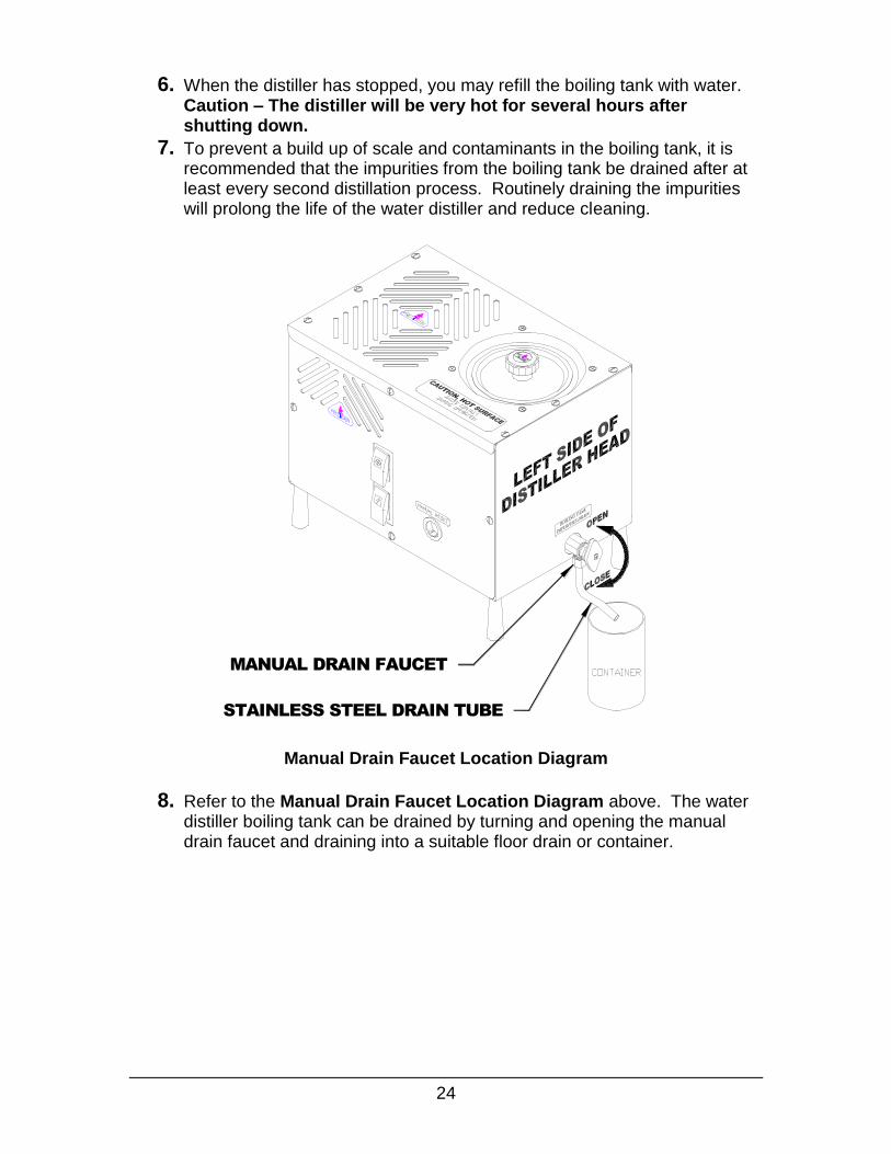
6. When the distiller has stopped, you may refill the boiling tank with water. Caution – The distiller will be very hot for several hours after shutting down.
7. To prevent a build up of scale and contaminants in the boiling tank, it is recommended that the impurities from the boiling tank be drained after at least every second distillation process. Routinely draining the impurities will prolong the life of the water distiller and reduce cleaning.
Manual Drain Faucet Location Diagram
8. Refer to the Manual Drain Faucet Location Diagram above. The water distiller boiling tank can be drained by turning and opening the manual drain faucet and draining into a suitable floor drain or container.
MANUAL DRAIN FAUCET
BOILING TANK DRAIN VALVE DIAGRAM
STAINLESS STEEL DRAIN TUBE

25
Introduction
The purpose of purchasing a water distiller is so you will not have to drink the unknown impurities in your drinking water. A water distiller effectively removes the impurities and chemicals from your water and returns the taste of pure water so that it is pleasing and healthy to drink for the entire family.
It is important to also keep the water distiller clean so that it can perform properly and efficiently. Regular cleaning and maintenance will allow the water distiller to continually provide pure water for a very long time.
Regular Inspection and Cleaning of the Boiling Tank 1. To prevent a build up of scale and contaminants in the boiling tank, it is
recommended that the impurities from the boiling tank be drained after at least every second distillation process. There may be an off colour line at the seams of the boiler tank, this is caused by the TIG welding process used during manufacturing. This is normal and is not a sign of any concern.
Manual Drain Faucet Location Diagram
2. Refer to the Manual Drain Faucet Location Diagram above. The water distiller boiling tank can be drained by opening the manual drain faucet and draining into a suitable floor drain or container.
3. It is important to develop a regular maintenance routine.
Maintenance and Cleaning
NOTE: Regular Cleaning is much easier than trying to clean after a prolonged period of time!
MANUAL DRAIN FAUCET
BOILING TANK DRAIN VALVE DIAGRAM
STAINLESS STEEL DRAIN TUBE

26
4. Check for scale build up on the walls of the boiler tank and the heating element. The heating element is the most critical. If there is 1/8” of build up or more on the heating element, then it is time to clean the boiling tank using the cleaner descaler. This process is described in the next section.
5. After checking the boiling tank every two weeks for about three months, you will be able to set up your own schedule as to how often the boiling tank needs to be cleaned with the cleaner descaler. Distilled water quantity use and raw water quality will determine your schedule.
Cleaning the Boiling Tank using the Cleaner Descaler
1. Turn all switches off and allow the water distiller to cool down.
2. Remove any loose scale from inside the boiling tank by hand through the boiler lid. If you are using the optional storage tank, remove the filter canister and place the sterilization tube onto the coil tube to by pass the optional storage tank. See Steam Sterilization of Water Distiller Head in this Maintenance and Cleaning section for more details.
3. Add 3 tablespoons of descaler cleaner to the boiling tank.
4. Fill the boiling tank half full with hot tap water.
5. Mix the cleaning solution well to dissolve the descaler in the water.
6. Fill up the remaining portion of the boiling tank with hot tap water to the bottom of the water gauge pin. See Boiling Tank Water Gauge Pin Diagram below.
Boiling Tank Water Gauge Pin Diagram
CAUTION: Descaler is a corrosive and poisonous substance. Read safety precautions on the package. As the initial water is added to the descaler in the boiling tank it will produce a bubbling foam substance. Do not overfill the boiling tank. Always leave boiling tank lid off when ever the boiling tank is being descaled to reduce fumes travelling through the cooling coil. Dispose of the first gallon of distilled water as a precaution.
BOILING TANK WATER LEVEL PIN DIAGRAM
BOILER FLOAT
WATER GAUGE
PIN
INSIDE BOILER
HEATING
ELEMENT
WATER LEVEL
IMPURITIES DRAIN
OUTLET

27
7. Let the solution stand overnight. Leave the boiling tank lid off during cleaning to prevent descaler fumes from entering the cooling coil.
8. The next morning or when the mineral content is soft, drain the boiling tank using the drain faucet. Remove any remaining loose scale by hand.
9. Repeat cleaning if necessary.
10.Once all the scale has been removed, rinse the boiling tank several times
with warm tap water.
11.Complete steam sterilization process on the boiling tank. See Steam
Sterilization in this Maintenance and Cleaning Section. Reinstall the filter canister.
12.The boiling tank is now clean and ready to produce pure water again.
Replacing Charcoal in Post Charcoal Filter Canister (Used with 8-M without Optional Storage Tank)
1. Turn all switches off and allow the water distiller to cool down.
Post Charcoal Filter Charcoal Replacement Diagram
2. Refer to the Post Charcoal Filter Charcoal Replacement Diagram above. Remove the feed tube from the filter by pulling it out of the filter.
3. Over a sink or suitable garbage can, remove the lid of the filter completely and empty charcoal from canister and rinse.
4. Fill canister 2/3 full with new charcoal and rinse over a sink or pail with approximately 2 cups of distilled water until water runs clear.
5. Press the filter cap back on to the post filter canister.
6. Insert the feed tube approximately ½” back into the hole on the side of the filter canister.
7. Place the filter on the side of any storage container or bottle.
NOTE: Replace charcoal in filter every 2 months or every 500 gallons of distilled water.
FILTER INSTALL DIAGRAM
FILTER CAP
FEED TUBE
WATER BOTTLE
POST CHARCOAL
FILTER
BULKHEAD, 3/8"JG
(INSIDE DISTILLER)
TUBE, SS, 3/8" X 1-1/2"

28
Replacing Charcoal in Charcoal Filter Canister (Used with 8-MST Optional Storage Tank)
1. Turn all switches off and allow the water distiller to cool down.
Filter Canister Charcoal Replacement Diagram
2. Refer to the Filter Canister Charcoal Replacement Diagram above. Remove the complete charcoal filter canister by lifting the front corner of the water distiller head.
3. Over a sink or suitable garbage can, remove the lid of the filter completely and empty charcoal from canister and rinse.
4. Fill canister 2/3 full with new charcoal and rinse over a sink or pail with approximately 2 cups of distilled water until water runs clear.
5. Press the filter cap back on to the filter canister.
6. Lift the corner of water distiller head and slide the filter into the storage tank and lower the water distiller head so the 3/8” tube enters the top of the filter.
NOTE: Replace charcoal in filter every 2 months or every 500 gallons of distilled water.
FILTER INSTALL DIAGRAM
BULKHEAD, 3/8"JG
(INSIDE DISTILLER)TUBE, SS, 3/8" X 1-1/2"
FILTER CAPCHARCOAL FILTER
CANISTER BODY

29
Introduction:
Steam Sterilization should be performed on the water distiller boiler and the optional storage tank before the water distiller is used for the first time or after a period of storage or non-use. After initial sterilization, the boiler should be steam sterilized after any maintenance is performed and/or cleaning including the descaling process. The optional storage tank requires cleaning and steam sterilization after any maintenance, or if there are any problems with the quality of the distilled water.
If there is a water quality concern and the system may be contaminated, it is important to first remove the source of contamination and remove all contaminated debris and then complete a Liquid Sterilization before a Steam Sterilization.
Liquid Sterilization of Optional Storage tank
1. It important to first remove the source of contamination and remove all contaminated debris before liquid sterilization.
2. Drain the water distiller.
3. Add 1/2 gallon of Liquid Sterilizing solution to the water distiller optional storage tank. If desired, spray some of the solution throughout the inside of the optional storage tank. Drain a small amount of the sterilizing solution out of the drain faucet to sterilize the faucet.
4. Wait 20 minutes and drain the sterilizing solution.
5. Rinse the entire inside of the optional storage tank with at least 2 gallons of distilled water.
6. Repeat the flushing of the optional storage tank with distilled water 2-3 times; continue until no chlorine smell is coming from the faucet.
7. Complete a Steam Sterilization of the boiling and optional storage tanks.
NOTE: This is performed whenever it is suspected that the water distiller head or optional storage tank are contaminated.
NOTE: Liquid Sterilization Solutions can be made from Household bleach. The bleach should be diluted to 100-200 PPM. Products such as Javex, have 6% Sodium Hypochlorite and should be diluted by placing 3 teaspoons per gallon of water. Always use Chlorine bleach that does not contain any other ingredients. Alternatively, Hydrogen Peroxide solutions may be used by placing 3 teaspoons per gallon of water.
Sterilization

30
1. Make sure the water distiller is cool before starting.
Steam Sterilization Diagram
2. Refer to the Steam Sterilization Diagram above. If you are using the optional storage tank, lift the front corner of the water distiller head and remove the charcoal filter.
3. Install the sterilization tube. Place the sterilization tube on the 3/8” stainless steel filter inlet tube on the bottom of the water distiller head.
4. Place the other end of the steam sterilization tube into a container as it will drip water and steam.
5. Fill the boiling tank with water to the bottom of the water gauge pin.
Steam Sterilization of Water Distiller Head
BULKHEAD,3/8"
(INSIDE DISTILLER)
STERILIZATION TUBE
3/8OD X 1-1/2"
SS TUBE
BULKHEAD,3/8"JG

31
Steam Sterilization Operation Switches Diagram
6. Refer to Steam Sterilization Operation Switches Diagram above. Turn only the power switch ON. Leave the fan switch OFF. As the water distiller continues to heat up, it will sterilize the water distiller with steam by allowing pure steam to travel out of the cooling coil. Water and steam will drip from the sterilization tube. Caution: The Water Distiller is extremely hot during sterilization.
7. Leave the water distiller on for 1 hour.
8. After the sterilization cycle is complete, turn the fan switch ON and allow any water in the cooling coil to drain. Leave the water distiller running with the fan on for about 15 minutes.
9. The water distiller will be very hot so turn all switches OFF (power and fan) and let the water distiller cool down for approximately 1 hour.
10. Remove the sterilization drip tube by pulling the plastic tube off the stainless steel charcoal filter inlet tube (keep the sterilization tube for future sterilizations).
11. Replace the charcoal in the post charcoal filter canister. See Replacing Charcoal in Post Charcoal Filter Canister (Used with 8-M without Optional Storage Tank) in this Maintenance and Cleaning Section.
12. The water distiller head is sterilized and ready for operation.
STEAM STERILIZATION OPERATION SWITCHES DIAGRAM
32
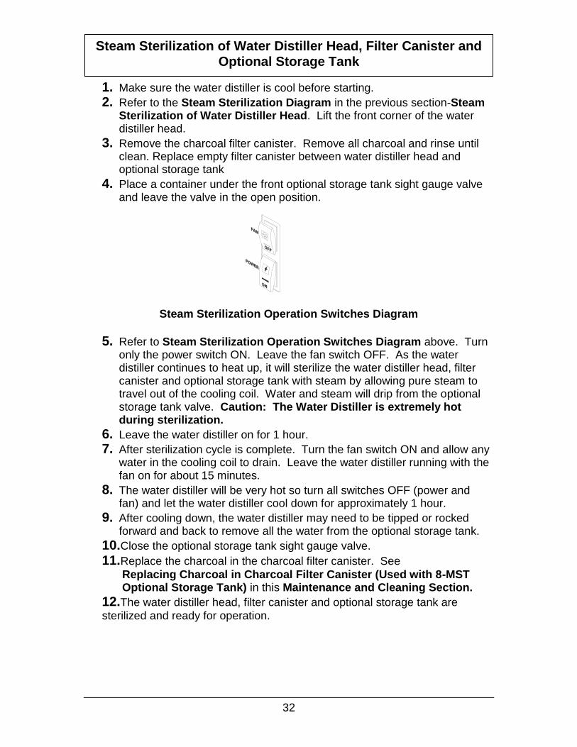
1. Make sure the water distiller is cool before starting.
2. Refer to the Steam Sterilization Diagram in the previous section-Steam Sterilization of Water Distiller Head. Lift the front corner of the water distiller head.
3. Remove the charcoal filter canister. Remove all charcoal and rinse until clean. Replace empty filter canister between water distiller head and optional storage tank
4. Place a container under the front optional storage tank sight gauge valve and leave the valve in the open position.
Steam Sterilization Operation Switches Diagram
5. Refer to Steam Sterilization Operation Switches Diagram above. Turn only the power switch ON. Leave the fan switch OFF. As the water distiller continues to heat up, it will sterilize the water distiller head, filter canister and optional storage tank with steam by allowing pure steam to travel out of the cooling coil. Water and steam will drip from the optional storage tank valve. Caution: The Water Distiller is extremely hot during sterilization.
6. Leave the water distiller on for 1 hour.
7. After sterilization cycle is complete. Turn the fan switch ON and allow any water in the cooling coil to drain. Leave the water distiller running with the fan on for about 15 minutes.
8. The water distiller will be very hot so turn all switches OFF (power and fan) and let the water distiller cool down for approximately 1 hour.
9. After cooling down, the water distiller may need to be tipped or rocked forward and back to remove all the water from the optional storage tank.
10.Close the optional storage tank sight gauge valve.
11.Replace the charcoal in the charcoal filter canister. See
Replacing Charcoal in Charcoal Filter Canister (Used with 8-MST Optional Storage Tank) in this Maintenance and Cleaning Section. 12.The water distiller head, filter canister and optional storage tank are
sterilized and ready for operation.
Steam Sterilization of Water Distiller Head, Filter Canister and Optional Storage Tank
STEAM STERILIZATION OPERATION SWITCHES DIAGRAM

33
Maintenance Schedule Table Initially Weekly Monthly Semi-
Annually Annually As
Needed 1) Check Scale Build Up. X X 2) Change Charcoal in Charcoal Filter Canister.
X X X
3) Clean Boiling Tank using Cleaner Descaler.
X X
4) Steam Sterilization of Boiling Tank after cleaning.
X
5) Steam Sterilization of Boiler and Optional Storage Tank.
X X
Owner Maintenance Record Table Change Charcoal
in Charcoal Filter Canister
Clean Boiling Tank using Cleaner Descaler
Steam Sterilization of Boiling Tank
Steam Sterilization of Boiling and Optional Storage Tank
Date Jan 21/03
Completed By BDR
Date
Completed By
Date
Completed By
Date
Completed By
Date
Completed By

34
PROBLEM CAUSE
A) Water distiller does not operate.
1. Water distiller is not plugged in securely to the wall outlet or the circuit breaker is off.
2. Power switch on the water distiller is turned off. 3. Reset button has shut the unit off. The reset
button will shut the unit off if the water distiller has overheated, it may be reset once the water distiller has cooled off. This may also indicate a problem and should be looked at by a service center. The reset button is a safety feature and is designed to shut the water distiller down should it overheat. Push your finger through the hole in the front cover labelled ‘Manual Reset’ to reset. It will snap once reset.
4. Reset button is faulty and needs to be replaced. Call Service Center.
B) Water is coming out from the top of the charcoal filter.
1. Charcoal is old and compacted. Replace coconut charcoal. See Maintenance section-Replacing Charcoal in Charcoal Filter Canister.
2. Charcoal filter is more than 2/3 full. There must be an air gap between the charcoal and the top of the filter. Remove Charcoal filter and make sure charcoal filter is only 2/3 full.
C) Steam or water is escaping from the top of the cooling coil.
1. The cooling coil is equipped with a gas release vent, a very small hole in the top of the coil. This is to release certain volatile gases. Steam may escape from this hole. This is normal.
2. If little or no water is being produced the cooling coil may have become disconnected from the boiling tank. Call Service Center.
Troubleshooting Caution! Always Disconnect Water Distiller Electrical plug and Let the
Water Distiller cool down completely before completing any Troubleshooting.

35
PROBLEM CAUSE D) Charcoal Filter is very hot and steam is escaping from the filter.
1. The fan switch is turned off. Check Switch. 2. Fan motor is not running properly, may be
defective, or the fan motor switch may be defective. Call Service Center.
3. Cooling coil fins are plugged with dust, dirt, or grease. Remove and clean or take to a service center for maintenance.
4. The location of the water distiller does not provide enough airflow for good cooling. Move the water distiller to an area with more air movement.
E) Water distiller may start to boil, then shuts off. It may restart after cooling down. Very small amount of water is produced.
1. Faulty Reset button. After letting water distiller cool down and trying to reset several times, call Service Center.
F) Water distiller runs properly but little or no water is produced.
1. Improper Heating Element is installed or Heating Element is faulty. Call Service Center.
2. Boiler tank lid is loose. Check by moving Boiler Tank Lid Knob.
3. Reset button may be defective or weak. See A) 3 above.
G) Strange taste in Distilled Water.
1. Boiling tank and/or optional storage tank may require cleaning. See maintenance section on cleaning water distiller.
2. Boiling tank was over filled. 3. Charcoal filter requires new Coconut Charcoal.
H) Fan does not operate automatically.
1. Fan switch is in OFF position. Check Switch. 2. Fan motor may be defective. Call Service
Center.
I) Distiller does not seem to produce as much water as specified.
See Section in Guide: 10 Factors That Will Affect Your Water Distiller Production.
Contact any Precision Water Systems Service Center to correct any problems with your water distiller that are not covered in this guide. To locate a Service Center in your area contact the manufacturer at: Precision Design & Manufacturing Inc. Westlock, Alberta, Canada T7P 2H7 http://www.precisionwaterdistillers.com Email: [email protected]
Phone: (780) 349 4933 FAX: (780) 349 4957

36
Additional Options
Water Distiller Cleaner and Descaler 600 g #500102 1600 g #500103
Used for regular maintenance to clean the scale out of the boiling tank. Dissolves water minerals in water distillers, coffeepots, dishwashers or most metal products where water scale is a problem.
DISTILLER CLEANER AND DESCALER DIAGRAM
Pure Activated Coconut Charcoal for Refillable Charcoal Filter Canisters
250 g #500106 600 g #500107
Contains 100% pure crushed coconut shells that have been steam activated at extremely high temperatures creating a porous grade of activated charcoal. This coconut charcoal can be used along with any type of home or commercial water distiller. Coconut charcoal is used to trap any gases or obnoxious odors that may escape the distillation process. Do not use any other charcoal such as aquarium type.
PURE ACTIVATED COCONUT CHARCOAL DIAGRAM
37
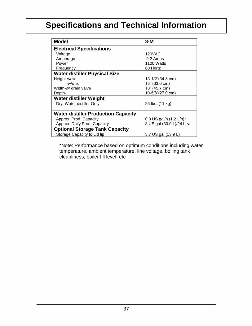
Model 8-M
Electrical Specifications Voltage Amperage Power Frequency
120VAC 9.2 Amps 1100 Watts 60 Hertz
Water distiller Physical Size Height-w/ lid -w/o lid Width-w/ drain valve Depth-
13-1/2”(34.3 cm) 13” (33.0 cm) 18” (45.7 cm) 10-5/8”(27.0 cm)
Water distiller Weight Dry: Water distiller Only
25 lbs. (11 kg)
Water distiller Production Capacity Approx. Prod. Capacity Approx. Daily Prod. Capacity
0.3 US gal/h (1.2 L/h)* 8 US gal (30.0 L)/24 hrs.
Optional Storage Tank Capacity Storage Capacity to Lid lip
3.7 US gal (13.9 L)
*Note: Performance based on optimum conditions including water temperature, ambient temperature, line voltage, boiling tank cleanliness, boiler fill level, etc
Specifications and Technical Information

38
Wiring List (8GPD Manual) Part # 500246-SERIES 15
No. Part# Color Ga Length From Conn. ToConn. From Location To Location
1 500287 GRN 16 3" #10RING#14-#16 POWER CORD GROUND POWER CORD
2 500287 BLK 16 14" F250 #14-#16 POWER CORD POWER SWITCH #2 POWER CORD
3 500287 WHT 16 16" #10RING#14-#16 POWER CORD RESET SWITCH #2 POWER CORD
4 500395 BLK 18 8" F250#18-#22&PIGG#18-#22 FAN MOTOR (ORG/BLU) FAN SWITCH #2 FAN MOTOR
5 500395 BLK 18 12" 2 (#10RING#18-#22) FAN MOTOR (YLW/WHT) RESET SWITCH #4 FAN MOTOR
6 095103 BLK 16 9" F250 #14-#16 #10 RING #14-#16 MICROSWITCH "NC" HEATING ELEMENT B
7 095024 YLW 16 6" #10RING#14-#16 #10 RING #14-#16 RESET SWITCH #3 HEATING ELEMENT A
8 095025 WHT 16 12" F250 #14-#16 #10 RING #14-#16 FAN SWITCH #3 HEATING ELEMENT B
9 095104 RED 16 7" F250 #14-#16 #10 RING #14-#16 MICROSWITCH "COM" RESET SWITCH #1
10 095027 ORG 16 9" F250 #14-#16 #10 RING #14-#16 POWER SWITCH #3 RESET SWITCH #4
11 095028 GRN 16 9" F250 #14-#16 #10 RING #14-#16 POWER SWITCH #8 RESET SWITCH #1
12 095029 BRN 16 9" F250 #14-#16 #10 RING #14-#16 FAN SWITCH #6 RESET SWITCH #4
13 095010 WHT 16 3" PIGG #14-#16 F250#14-#16 FAN SWITCH #2 FAN SWITCH #7
14 095010 WHT 16 3" PIGG #14-#16 F250#14-#16 POWER SWITCH #3 POWER SWITCH #6
15 095031 BRN 16 13" F250 #14-#16 #10 RING #14-#16 POWER SWITCH #7 HEATING ELEMENT B
16 095032 BLU 16 10" #10RING#14-#16 F250 #14-#16 RESET SWITCH #3 FAN SWITCH #8

39
WIRING DIAGRAM, 8GPD MANUAL

40
Boiling Tank Lid, 22
Capacities
distilled production, 41
storage tank, 41
Charcoal
changing, 30, 31
Charcoal Filter
Installing Canister, 31
Charcoal Filter Canister
replacing charcoal, 31
Cleaning
boiling tank using the cleaner descaler, 28
regular inspection/cleaning of the boiling tank, 27
Descaler
instructions, 28
Electrical
location, 14
requirements, 14
Hydrological Cycle, 13
Inspection-boiling tank, 27
Installation
drain tube, 21
water distiller tools, 17
Lid
boiling tank, 22
storage tank, 22
Location-suitable distiller, 14
Maintenance and Cleaning, 27
record table, 37
schedule, 37
Operation, 23
fan switch, 24
normal, 25
overheat reset switch, 24
power switch, 24
Options
charcoal-replacement order, 40
cleaner and descaler-replacement order, 40
Post Charcoal Filter
replacing charcoal, 30
Record of purchase, 5
Safety Precautions, 7
Service Centre Locator, 39
Shipping Tie Removal, 17
Startup- Summary, 8
Sterilization, 32
liquid- optional storage tank, 32
steam- water distiller head, 33
steam- water distiller head, filter canister and
optional storage tank, 35
Terminology, 9
Troubleshooting, 38
Warranty, 6
Weights, 41
Index

41
Precision Water Systems Water Distiller
Warranty Registration
IMPORTANT! Precision Water Systems IMPORTANT!
Thank you for purchasing this fine Precision Water Systems Water Distiller.
Please complete the information below and return it within the next ten days so we may register your purchase.
Last Name First Name
Address: (Mailing)
City Province/State Country
Zip Code/Postal Code
Date of Purchase:
Month Day Year Phone Number:
Model Number Serial Number Series:
8-M (Water Distiller) Model Number Serial Number Series:
8-MST (Optional Storage Tank)
Purchased From:
Please fill in information completely and mail directly to:
Precision Design & Manufacturing Inc. 10331 – 105th Street
Westlock, Alberta, Canada T7P 2H7
Or Fax To: 780-349-4957