precont pn4sm
TRANSCRIPT

07.17Technical manual
ApplicationsGeneral applications in• Machinery and plant engineering• Air-conditioning and refrigeration plant engineering• Hydraulic and pneumatic systems• Process industry• Environmental technology• Facility and building automation
Precont PN4SM
Pressure transmitter / Pressure switch with data memoryfor general applicationsMonitoring of absolute or relative pressure in gases, vapors, liquids and dust
Main featuresWide range of applications• Finely graded measuring ranges from 400 mbar up to 1000
bar• Wide process temperature range –40°C to +125°C• Wide variety of process connections • High protection class IP65 / IP67• Wide environmental temperature range –20°C to +70°C
Metallic front-flush or internal diaphragm
Highest accuracy – characteristic deviation to ≤ 0,15% of measuring range
Integrated evaluation electronic• Graphic display, keyboard• 4x PNP switch output• 1x current output 0/4…20mA – voltage output 0…10V• Measure data memory for more than 500.000 measuring
values• Battery powered data logger function• Bluetooth-Interface• Connector plug M12
High operating comfort• Enclosure and display rotatable for optimal operability in
each installation position• High contrast high brightness TFT-LCD display for best
readability• 3-key operation without additional assistance with tactile
feedback• Easy handling by clear menu navigation• Extensive diagnostic functions for system analysis

ACS-CONTROL-SYSTEM GmbH l Lauterbachstr. 57 l D-84307 Eggenfelden l www.acs-controlsystem.de l [email protected]
You have purchased a high-grade and modern measuring device of ACS-CONTROL-SYSTEM GmbH.
We want to give thanks for your purchase and for your confidence to us.
The actual technical manual includes instructions for installation, electrical connection and inauguration, as well as the technical data of the device.
Modifications, that answer the purpose of the technical progress, are reserved byACS-CONTROL-SYSTEM GmbH without prior notice.
If a question occurs, that can‘t be answered by the listed informations, please call on our technicians team in Eggenfelden Tel: +49 8721/ 9668-0 or [email protected]
All rights reserved
ACS-CONTROL-SYSTEM GmbH l Lauterbachstr. 57 l D-84307 Eggenfelden l www.acs-controlsystem.de l [email protected] 3
Index1 System description . . . . . . . . . . . . . . . . . . . . . . . . . . . . . . . . . . . . . . . . . . . . . . . . 4
1.1 Intended use ................................................... 41.2 Field of application ........................................... 41.3 System components ......................................... 51.4 Function ......................................................... 5
2 Safety notes . . . . . . . . . . . . . . . . . . . . . . . . . . . . . . . . . . . . . . . . . . . . . . . . . . . . . 62.1 Operational safety ............................................ 62.2 Installation, connection, commissioning, operation 6
3 Installation . . . . . . . . . . . . . . . . . . . . . . . . . . . . . . . . . . . . . . . . . . . . . . . . . . . . . . 73.1 Installation place ............................................. 73.2 Process and environmental temperature ............. 73.3 Installation notes ............................................. 73.4 Air pressure compensation ................................ 7
4 Electrical connection . . . . . . . . . . . . . . . . . . . . . . . . . . . . . . . . . . . . . . . . . . . . . . 84.1 Potential equalization - earthing ......................... 84.2 Connection cable ............................................. 84.3 Supply voltage ................................................ 84.4 Switch output .................................................. 84.5 Analogue output .............................................. 94.6 Connection scheme .......................................... 9
5 Operation . . . . . . . . . . . . . . . . . . . . . . . . . . . . . . . . . . . . . . . . . . . . . . . . . . . . . . 115.1 Operation and display parts ............................... 115.2 Function scheme .............................................. 125.3 Menu structure ................................................ 145.4 Navigation ...................................................... 155.5 Output ........................................................... 165.6 Basic setting ................................................... 235.7 Display ........................................................... 285.8 Simulation – E ................................................. 335.9 Diagnosis ........................................................ 345.10 Data .............................................................. 375.11 Start-up procedure ........................................... 425.12 Software history .............................................. 46
6 Service . . . . . . . . . . . . . . . . . . . . . . . . . . . . . . . . . . . . . . . . . . . . . . . . . . . . . . . . 476.1 Maintenance .................................................... 476.2 Dismounting.................................................... 476.3 Repair ............................................................ 476.4 Return ............................................................ 476.5 Disposal ......................................................... 47
7 Technical Data . . . . . . . . . . . . . . . . . . . . . . . . . . . . . . . . . . . . . . . . . . . . . . . . . . 487.1 Auxiliary power supply ...................................... 487.2 Output ........................................................... 487.3 Measuring accuracy .......................................... 497.4 Clock .............................................................. 497.5 Interface Bluetooth .......................................... 497.6 Data memory .................................................. 507.7 Process conditions ............................................ 507.8 Environmental conditions .................................. 507.9 Materials - process wetted ................................ 517.10 Materials - not process wetted ........................... 51
8 Dimension drawings . . . . . . . . . . . . . . . . . . . . . . . . . . . . . . . . . . . . . . . . . . . . . . 528.1 Terminal enclosure ........................................... 528.2 Temperature decoupler ..................................... 528.3 Process connection ........................................... 53
9 Ordering information . . . . . . . . . . . . . . . . . . . . . . . . . . . . . . . . . . . . . . . . . . . . . 559.1 Order code ...................................................... 559.2 Additional options ............................................ 569.3 Accessories ..................................................... 56
ACS-CONTROL-SYSTEM GmbH l Lauterbachstr. 57 l D-84307 Eggenfelden l www.acs-controlsystem.de l [email protected]
1 System description
1 .1 Intended useThe device is an electronic pressure transmitter / pressure switch for monitoring, control as well as continuous measurement of pressures in gases, vapors, liquids and dusts.
The operational reliability of the device is ensured only at the intended use.
1 .2 Field of applicationDue to the device construction with
• Measuring ranges from -1 bar to 1000 bar, gauge• Measuring ranges from 0 bar to 1000 bar, absolute• Measuring spans from 400 mbar to 1000 bar• Process temperatures from –40°C to +125°C• Process material CrNi-steel
as well as the availability of industrial standard process connections like• thread ISO 228-1, EN 837 manometer• thread ISO 228-1, front-flush
the device is especially suitable for the use for• Machinery and plant engineering• Air-conditioning and refrigeration plant engineering• Hydraulic and pneumatic systems• Process industry• Environmental technology• Facility and building automation
The device is suitable for demanding measuring requirements.
Due to its high accuracy and the high flexibility of configuration, the device can be suited a wide variety of applications.
The front-flush diaphragm has been specifically designed for the measurement of viscous, paste-like, adhesive, crystallizing, particle-laden and contaminated media, which would clog the pressure channel of conventional process connections.
The robust design and the high-quality workmanship turns the device into a very high quality product, which even the most adverse environmental conditions cannot affect, whether low temperatures when used outdoors, high shock and vibration or aggressive media.
A captive laser marking of the type label ensures the identifiability throughout the entire lifetime of the device.Obviously is the optional marking of a measurement point designation resp. TAG, a customer label or of a neutral type label, of course also per laser marking.
A LABS-free resp. silicone-free version, a factory calibration with calibration certificate and a customer specific configuration resp. preset is also optionally available like factory certifications for drink water resp. food suitability.
Customer specific special versions can be realized on request, e.g.• software adaption (menu navigation, special functions, etc.),• changed terminal assignment resp. connector orientation,• design adaption of the user surface,• extended process temperature range up to 400°C• special designs for the process connection• other process materials• other fill fluids• special adjustment
ACS-CONTROL-SYSTEM GmbH l Lauterbachstr. 57 l D-84307 Eggenfelden l www.acs-controlsystem.de l [email protected] 5
1 .3 System componentsThe device consists on the components:
• Process connection, for installation into the wall of the container or of the pipeline.• Process diaphragm as junction point in direct contact with the applied medium, fill fluid for the
pressure transfer (only measuring ranges ≤ 25 bar resp. front-flush diaphragm) and pressure measuring sensor.
• Temperature decoupler, for decoupling of the terminal enclosure from high process temperatures.
• Terminal enclosure, rotatable by 300°, for protection of the integrated signal processing electronic and for the electrical connection.
The components cannot be separated by the user.
1 .4 Function1 .4 .1 Measuring principle
At process connections with internal metallic diaphragm and measuring ranges ≥ 40 bar, the system pressure is directly applied to the pressure measuring sensor. A dry pressure measuring sensor is used, without using a fill fluid.
At process connections with front-flush metallic diaphragm resp. at measuring ranges ≤ 25 bar the system pressure is transferred by a fill fluid from the diaphragm to the pressure measuring sensor, which is positioned behind.
The pressure dependent deflection of the diaphragm is transferred to a measuring bridge and causes there a change of the bridge output voltage.
1 .4 .2 Signal processingThe pressure signal is converted by the pressure measuring sensor into an electrical signal and processed by the integrated evaluation electronic according to the respective preferences:
• The measuring value is monitored by four PNP switch outputs for exceedance of limit values.• The measuring value is converted into a continuous current signal 0/4...20mA or voltage signal
0…10V.• The measuring value is diagrammed at the high brightness and high contrast TFT-LCD display,
whereby it can be selected between different display styles (digital value / manometer / chart / bar graph).
• All settings can be changed comfortable and easy by a 3-key operation without additional assistance with tactile feedback.
The device includes numerous functions to the adaption to nearly each measuring task:• Integrated unit conversion• Peak value memory minimum – maximum• Error memory for fast failure analysis• Various flexible switch functions• Error indication function to switch output, current/voltage output and display• Simulation of the switch outputs and the current/voltage output
In the internal ring memory more than 500.000 measuring values can be recorded durable.At the data logger function these measuring values are marked with a battery powered time stamp.By the Bluetooth interface recorded measuring values can be downloaded.
ACS-CONTROL-SYSTEM GmbH l Lauterbachstr. 57 l D-84307 Eggenfelden l www.acs-controlsystem.de l [email protected]
2 Safety notes2 .1 Operational safety
The device is safely built and tested according to state-of-the-art technology and has left the factory in perfect condition as regards technical safety.
The device meets the legal requirements of all relevant EU directives. This is confirmed by attaching the CE mark.
This measuring device meets article 4 (3) of the EU directive 2014/68/EU (pressure equipment device directive) and is designed and produced in good engineer practice.Devices with measurement end value > 200 bar are constructed for media of fluid group 2.
2 .2 Installation, connection, commissioning, operationInstallation, electrical connection, commissioning and operation of the device must be made by a qualified and authorized expert according to the information’s in this technical manual and the relevant standards and rules. This expert must have read and understood this technical manual and especially the safety notes.
The device may only be used within the permitted operation limits that are listed in this technical manual. Every use besides these limits as agreed can lead to serious dangers.
The materials of the device must be checked for compatibility with the respective application requirements (contacting materials, process temperature) before use. An unsuitable material can lead to damage, abnormal behavior or destruction of the device and to the resulting dangers.
The sensors may not be used as sole device for prevention of dangerous conditions in machines and plants.
Using the device in a manner that does not fall within the scope of its intended use, disregarding this instruction, using under-qualified personnel, or making unauthorized alterations releases the manufacturer from liability for any resulting damage. This renders the manufacturer‘s warranty null and void.
ACS-CONTROL-SYSTEM GmbH l Lauterbachstr. 57 l D-84307 Eggenfelden l www.acs-controlsystem.de l [email protected] 7
3 InstallationThe correct function of the device within the specific technical data can only be guaranteed, if the permitted process and environmental temperatures (see chapter „Technical data“) will not be exceeded.
3 .1 Installation placeThe installation of the device at locations where high pressure blows can occur should be avoided.
At a pressure measurement in gases, the device should be installed above the tapping point, so that the condensate can flow into the process.
At a pressure measurement in steams, the device should be installed after a siphon and a shut-off device below the tapping point. The siphon reduces the temperature to almost ambient temperature. Fill the siphon with fluid before commissioning.
At a pressure measurement in liquids, the device should be installed after a shut-off device below or at the same level as the tapping point.
At a filling level measurement in liquids, the device should be installed below the lowest measuring point. Do not mount the device in the fill flow, in the suction area of a pump, in the tank outlet or at a point in the container which could be affected by pressure pulses from an agitator. Calibration and functional test can be carried out more easily if you mount the device after a shut-off device.
The installation position can have an influence on the measuring result of the kind of a zero value shift because of the deadweight of the measuring diaphragm. The correction of this deviation at the device is possible.
3 .2 Process and environmental temperatureThe installation of the device should be made if possible at temperature calmed places to get a reliable measuring result.
Strong temperature steps, e.g. at filling of a hot liquid into a cold system, can produce a short-time higher measuring signal deviation.
At high process temperatures a heat transfer to the terminal enclosure can be reduced by isolation of the medium carrying part of the plant.
3 .3 Installation notesDrive the system pressure free prior installation resp. deinstallation of the sensor.
The protective cap, which is attached at the diaphragm, must only be removed immediately before the installation.
The diaphragm must not be point loaded, because this can lead to diaphragm damage.
The installation of the device into a closed off completely with process liquid filled connection can lead to destruction of the measuring diaphragm. The reduction of the volume of the liquid at screw-in leads to a very high pressure boosting, which can exceed the permitted maximum value by a multiple. Thus, before installation, the connection must be sufficiently emptied.
The screw-in of the thread process connection by using the terminal enclosure, the connection plug resp. the connection cable is not permitted.The tightening of the thread process connection may only be done at the hexagon by a suitable spanner and with the maximum permitted torque strength (see chapter „Technical data“).
3 .4 Air pressure compensationAvoid the damaging or pollution of the pressure compensation system.The hindrance of the pressure compensation can lead to faulty measuring results.The filter element of the pressure compensation system is positioned at the side of the enclosure.
ACS-CONTROL-SYSTEM GmbH l Lauterbachstr. 57 l D-84307 Eggenfelden l www.acs-controlsystem.de l [email protected]
4 Electrical connectionThe electrical connection of the device must be carried out according to the respective country specific standards.Incorrect installation or adjustment could cause applicationally conditioned risks.
Warning!The instrument may only be installed if the supply voltage is switched off.
4 .1 Potential equalization - earthingThe device must be grounded.The earthing can be carried out by the metallic process connection.The metallic parts of the device are electrically connected with the socket of the plug M12.
4 .2 Connection cableUse only shielded signal and measurement wires and install these wires separated from power leading wires. Connect the cable shield of a connected cable only at one side to earth, ideally at the installation place of the device.
4 .3 Supply voltageThe voltage applied to the terminal contacts may not exceed the maximum permitted supply voltage to avoid damage of the electronic.The maximum permitted supply voltage range is:
Signal 0/4…20mA 9…30VDC
Signal 0…10V 14…30VDC
All connections are reverse polarity protected.
4 .4 Switch outputWarning!Inductive loads at the PNP switch outputs, e.g. relays, contactors or magnetic vents may only be used with a free-wheeling diode or a RC protection circuit to avoid high voltage peaks.
Note!For inauguration it is suggested, to deactivate all connected control devices, to avoid unwanted control reactions.
The load at the PNP switch output will be connected to the terminal +L of the supply voltage by a semiconductor switch contactless and by this bounce-free.At an activated switch state a positive signal near supply voltage is feed to the output.At deactivated switch state and at failure of supply voltage the semiconductor switch is shut off.The PNP switch output is current limited, overload and short circuit protected.
ACS-CONTROL-SYSTEM GmbH l Lauterbachstr. 57 l D-84307 Eggenfelden l www.acs-controlsystem.de l [email protected] 9
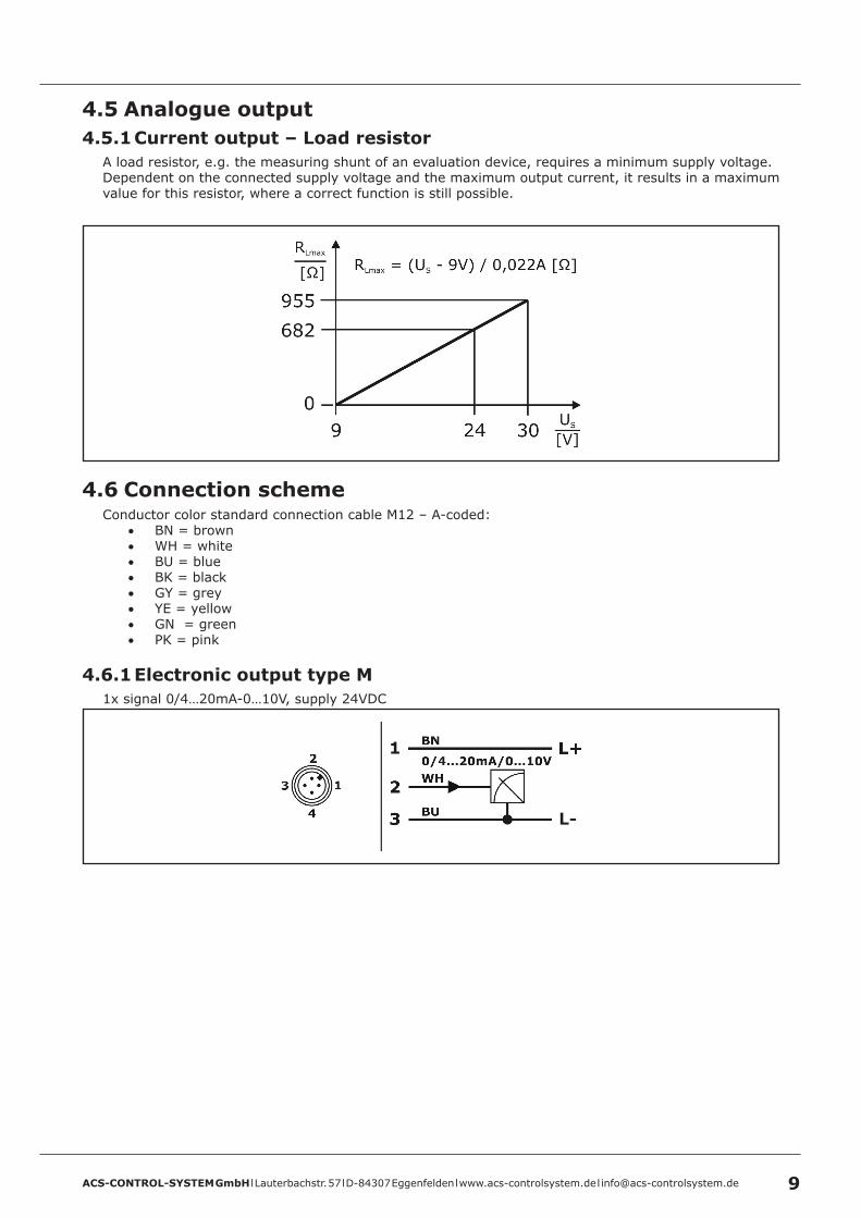
4 .5 Analogue output4 .5 .1 Current output – Load resistor
A load resistor, e.g. the measuring shunt of an evaluation device, requires a minimum supply voltage. Dependent on the connected supply voltage and the maximum output current, it results in a maximum value for this resistor, where a correct function is still possible.
4 .6 Connection schemeConductor color standard connection cable M12 – A-coded:
• BN = brown• WH = white• BU = blue• BK = black• GY = grey• YE = yellow• GN = green• PK = pink
4 .6 .1 Electronic output type M1x signal 0/4…20mA-0…10V, supply 24VDC
ACS-CONTROL-SYSTEM GmbH l Lauterbachstr. 57 l D-84307 Eggenfelden l www.acs-controlsystem.de l [email protected]
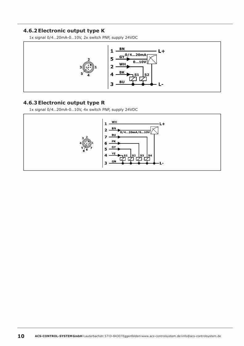
4 .6 .2 Electronic output type K1x signal 0/4…20mA-0…10V, 2x switch PNP, supply 24VDC
4 .6 .3 Electronic output type R1x signal 0/4…20mA-0…10V, 4x switch PNP, supply 24VDC
ACS-CONTROL-SYSTEM GmbH l Lauterbachstr. 57 l D-84307 Eggenfelden l www.acs-controlsystem.de l [email protected] 11
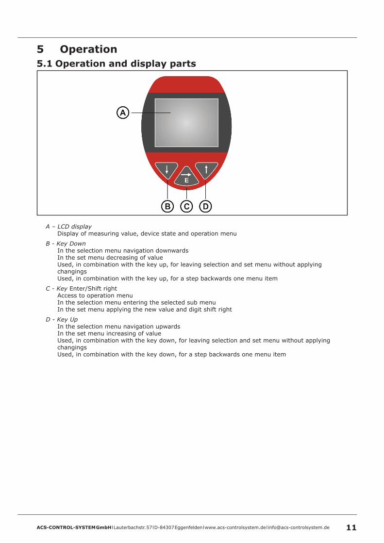
5 Operation5 .1 Operation and display parts
A – LCD displayDisplay of measuring value, device state and operation menu
B - Key DownIn the selection menu navigation downwardsIn the set menu decreasing of valueUsed, in combination with the key up, for leaving selection and set menu without applying changingsUsed, in combination with the key up, for a step backwards one menu item
C - Key Enter/Shift rightAccess to operation menuIn the selection menu entering the selected sub menuIn the set menu applying the new value and digit shift right
D - Key UpIn the selection menu navigation upwardsIn the set menu increasing of valueUsed, in combination with the key down, for leaving selection and set menu without applying changingsUsed, in combination with the key down, for a step backwards one menu item
ACS-CONTROL-SYSTEM GmbH l Lauterbachstr. 57 l D-84307 Eggenfelden l www.acs-controlsystem.de l [email protected]
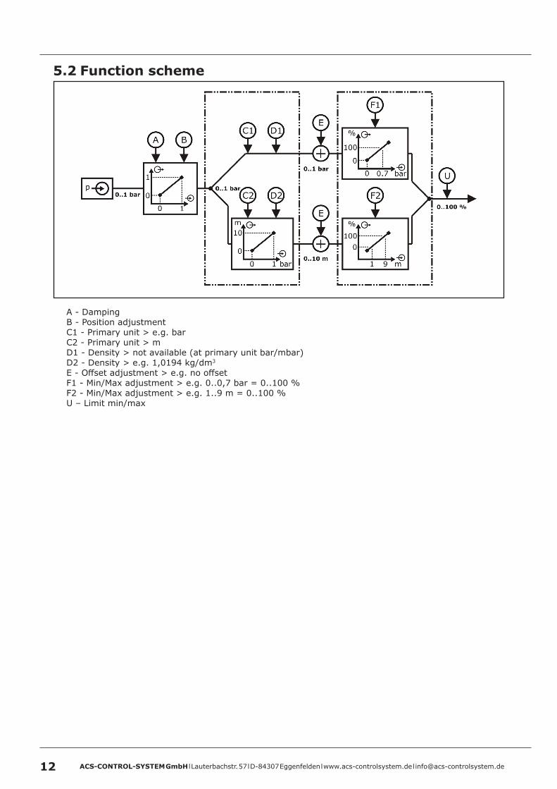
5 .2 Function scheme
A - DampingB - Position adjustmentC1 - Primary unit > e.g. barC2 - Primary unit > mD1 - Density > not available (at primary unit bar/mbar)D2 - Density > e.g. 1,0194 kg/dm3
E - Offset adjustment > e.g. no offsetF1 - Min/Max adjustment > e.g. 0..0,7 bar = 0..100 %F2 - Min/Max adjustment > e.g. 1..9 m = 0..100 %U – Limit min/max
ACS-CONTROL-SYSTEM GmbH l Lauterbachstr. 57 l D-84307 Eggenfelden l www.acs-controlsystem.de l [email protected] 13
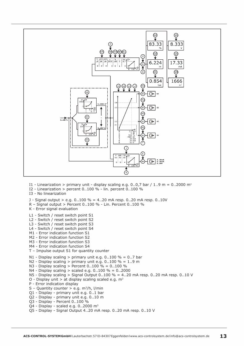
I1 - Linearization > primary unit - display scaling e.g. 0..0,7 bar / 1..9 m = 0..2000 m3
I2 - Linearization > percent 0..100 % - lin. percent 0..100 %I3 - No linearization
J - Signal output > e.g. 0..100 % = 4..20 mA resp. 0..20 mA resp. 0..10VR – Signal output > Percent 0..100 % - Lin. Percent 0..100 %K - Error signal evaluation
L1 - Switch / reset switch point S1L2 - Switch / reset switch point S2L3 - Switch / reset switch point S3L4 - Switch / reset switch point S4M1 - Error indication function S1M2 - Error indication function S2M3 - Error indication function S3M4 - Error indication function S4T – Impulse output S1 for quantity counter
N1 - Display scaling > primary unit e.g. 0..100 % = 0..7 bar N2 - Display scaling > primary unit e.g. 0..100 % = 1..9 m N3 - Display scaling > Percent 0..100 % = 0..100 %N4 - Display scaling > scaled e.g. 0..100 % = 0..2000N5 - Display scaling > Signal Output 0..100 % = 4..20 mA resp. 0..20 mA resp. 0..10 VO - Display unit > at display scaling scaled e.g. m3
P - Error indication displayS – Quantity counter > e.g. m3/h, l/minQ1 - Display - primary unit e.g. 0..1 barQ2 - Display - primary unit e.g. 0..10 mQ3 - Display - Percent 0..100 %Q4 - Display - scaled e.g. 0..2000 m3
Q5 - Display - Signal Output 4..20 mA resp. 0..20 mA resp. 0..10 V
ACS-CONTROL-SYSTEM GmbH l Lauterbachstr. 57 l D-84307 Eggenfelden l www.acs-controlsystem.de l [email protected]
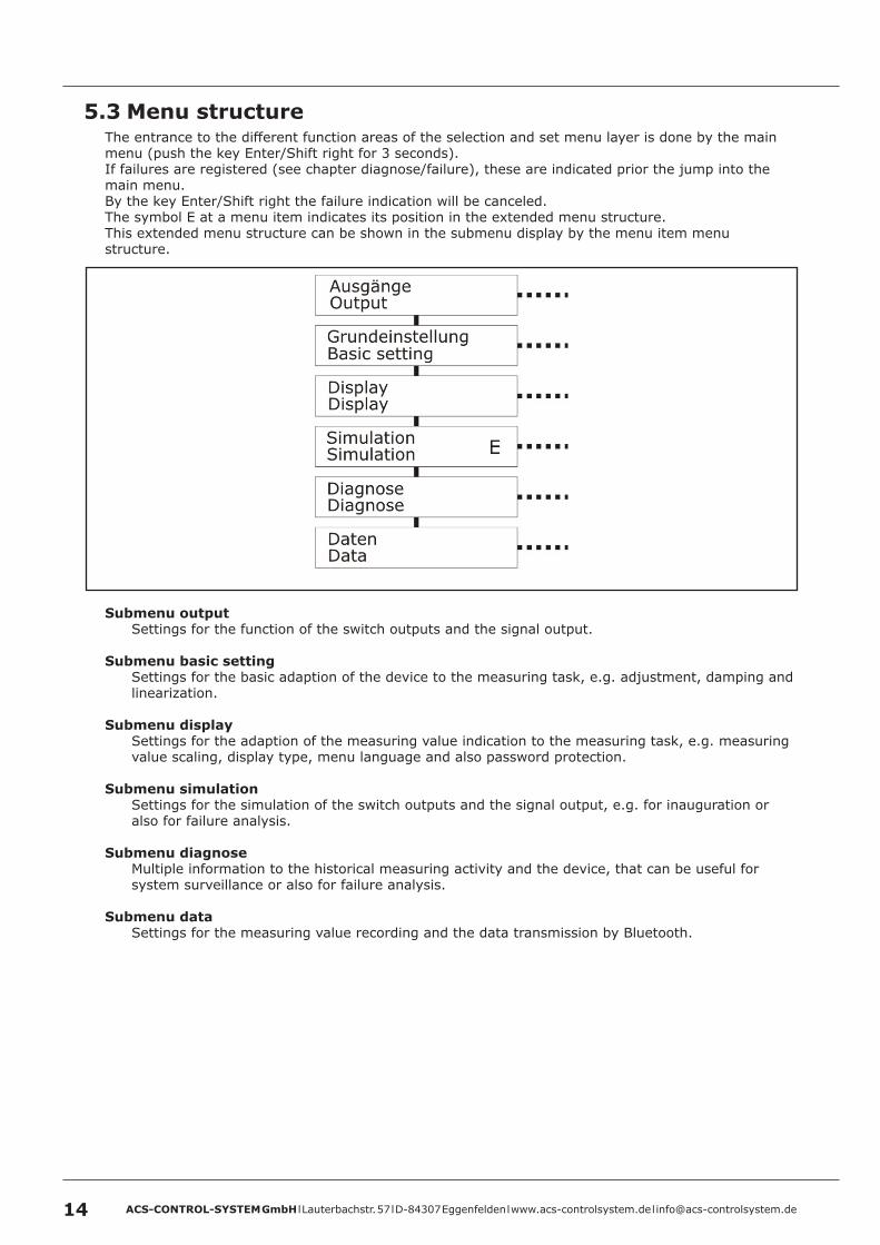
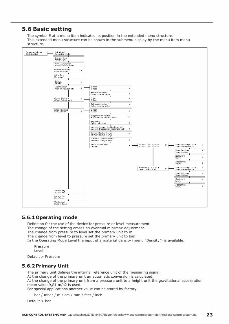
5 .3 Menu structureThe entrance to the different function areas of the selection and set menu layer is done by the main menu (push the key Enter/Shift right for 3 seconds).If failures are registered (see chapter diagnose/failure), these are indicated prior the jump into the main menu.By the key Enter/Shift right the failure indication will be canceled.The symbol E at a menu item indicates its position in the extended menu structure.This extended menu structure can be shown in the submenu display by the menu item menu structure.
Submenu outputSettings for the function of the switch outputs and the signal output.
Submenu basic setting Settings for the basic adaption of the device to the measuring task, e.g. adjustment, damping and linearization.
Submenu displaySettings for the adaption of the measuring value indication to the measuring task, e.g. measuring value scaling, display type, menu language and also password protection.
Submenu simulationSettings for the simulation of the switch outputs and the signal output, e.g. for inauguration or also for failure analysis.
Submenu diagnoseMultiple information to the historical measuring activity and the device, that can be useful for system surveillance or also for failure analysis.
Submenu dataSettings for the measuring value recording and the data transmission by Bluetooth.
ACS-CONTROL-SYSTEM GmbH l Lauterbachstr. 57 l D-84307 Eggenfelden l www.acs-controlsystem.de l [email protected] 15
5 .4 NavigationThe navigation in a submenu and in a selection window is done by the keys Up and Down.The selection of a submenu and the selection of a setting in a selection menu is done by the key Enter/Shift right.The jump backward from a submenu to the higher-level menu is done by the menu item back or by the simultaneous pushing the keys Up and Down.The leaving of a selection menu without applying the changings is done by the simultaneous pushing the keys Up and Down.
The input of a value or text in a set menu is done digit by digit.For the changing of the selected digit the keys Up and Down are used.For the changing of the digit the key Enter/Shift right is used.The applying of a set value resp. text is done by pushing the key Enter/Shift right for 3 seconds.The leaving of an set menu without applying a value resp. text is done by the simultaneous pushing the keys Up and Down.
After 5 minutes of inactivity the active submenu resp. selection menu will automatically be left and a change to the measuring value indication is executed.A jump backward is not executed from an active set menu.
ACS-CONTROL-SYSTEM GmbH l Lauterbachstr. 57 l D-84307 Eggenfelden l www.acs-controlsystem.de l [email protected]
5 .5 OutputThe symbol E at a menu item indicates its position in the extended menu structure.This extended menu structure can be shown in the submenu display by the menu item menu structure.
5 .5 .1 Switch output S1 / S2 / S3 / S45 .5 .1 .1 Enabled
Each switch output can be activated resp. deactivated separately.
YesNo
Default > Yes
5 .5 .1 .2 Switch Point / Reset Switch PointThe input values refers to the set display value, in the set primary unit or acc. to display scaling.The reset switch point must be lower or equal to the switch point.
The input range is limited to the measuring range.Default > S1 = 20% / S2 = 40% / S3 = 60% / S4 = 80%
5 .5 .1 .3 Switch Delay Time / Reset Switch Delay Time – EThe activation resp. deactivation of the switch output can be biased with a delay time (resolution 0,01s), to realize simple sequence control system.
The input range is indefinite.Default > 0s
ACS-CONTROL-SYSTEM GmbH l Lauterbachstr. 57 l D-84307 Eggenfelden l www.acs-controlsystem.de l [email protected] 17
5 .5 .1 .4 Function - E5 .5 .1 .4 .1 Hysteresis function S1/S2/S3/S4
The hysteresis function realizes a stable switch state, independent from system conditioned signal fluctuations around the adjusted set point.It can be used for realizing a signal controlled two-position control.The switch range is determined by definition of switch point and reset switch point.
In the menu Operating Mode, the working principle of the switch output can be inverted.
Operating Mode Maximum
The switch output is activated, if the current measuring value overshoots the switch point and if the set switch point delay time has been expired.The switch output is deactivated, if the current measuring value undershoots the reset switch point and if the set reset switch point delay time has been expired.
Operating Mode Minimum
The switch output is activated, if the current measuring value undershoots the reset switch point and if the set reset switch point delay time has been expired.The switch output is deactivated, if the current measuring value overshoots the switch point and if the set switch point delay time has been expired.
ACS-CONTROL-SYSTEM GmbH l Lauterbachstr. 57 l D-84307 Eggenfelden l www.acs-controlsystem.de l [email protected]
5 .5 .1 .4 .2 Window function S1/S2/S3/S4
The window function realizes a signal range – acceptance region –, where the switch output is set to a definitive switch state.The switch range is determined by definition of switch point, reset switch point and hysteresis.
In the menu Operating Mode, the working principle of the switch output can be inverted.
Operating Mode outside
The switch output is activated, if the current measuring value is outside the area that is defined by the switch point and the reset switch point and if the set switch point delay time has been expired.The switch output is deactivated, if the current measuring value is inside the area that is defined by the switch point and the reset switch point and if the set reset switch point delay time has been expired.The hysteresis is positioned inside the area that is defined by the switch point and the reset switch point.
Operating Mode inside
The switch output is activated, if the current measuring value is inside the area that is defined by the switch point and the reset switch point and if the set switch point delay time has been expired.The switch output is deactivated, if the current measuring value is outside the area that is defined by the switch point and the reset switch point and if the set reset switch point delay time has been expired.The hysteresis is positioned outside the area that is defined by the switch point and the reset switch point.
5 .5 .1 .4 .3 Error Indication Function S1/S2/S3/S4
The switch output is activated, if the device has detected a failure behavior (see chapter diagnose/failures).
In the menu Operating Mode, the working principle of the switch output can be inverted.
5 .5 .1 .4 .4 Impulse Function S1
The switch output generates one switch impulse per calculated quantity value of the quantity counter (see data/quantity counter).A warning message is generated, if the quantity counter impulse value is set too low or the impulse length is set too high. The calculation base for this warning message is the display scaling at 100%.
Quantity counter impulse valueAmount of the quantity counter value, for which one switch impulse is generated.
The input range is indefinite.Default > 1
ACS-CONTROL-SYSTEM GmbH l Lauterbachstr. 57 l D-84307 Eggenfelden l www.acs-controlsystem.de l [email protected] 19
Impulse lengthDuration of a pulse resp. additionally the duration of a pulse pause.
The input range is limited to values from 0,1 to 99999.Default > 0,5 s
In the menu Operating Mode, the working principle of the switch output can be inverted.
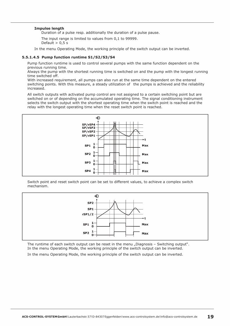
5 .5 .1 .4 .5 Pump function runtime S1/S2/S3/S4
Pump function runtime is used to control several pumps with the same function dependent on the previous running time. Always the pump with the shortest running time is switched on and the pump with the longest running time switched off.With increased requirement, all pumps can also run at the same time dependent on the entered switching points. With this measure, a steady utilization of the pumps is achieved and the reliability increased.
All switch outputs with activated pump control are not assigned to a certain switching point but are switched on or of depending on the accumulated operating time. The signal conditioning instrument selects the switch output with the shortest operating time when the switch point is reached and the relay with the longest operating time when the reset switch point is reached.
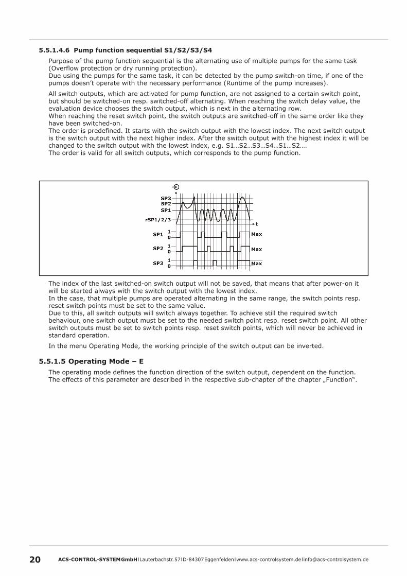
Switch point and reset switch point can be set to different values, to achieve a complex switch mechanism.
The runtime of each switch output can be reset in the menu „Diagnosis – Switching output“.In the menu Operating Mode, the working principle of the switch output can be inverted.
In the menu Operating Mode, the working principle of the switch output can be inverted.
ACS-CONTROL-SYSTEM GmbH l Lauterbachstr. 57 l D-84307 Eggenfelden l www.acs-controlsystem.de l [email protected]
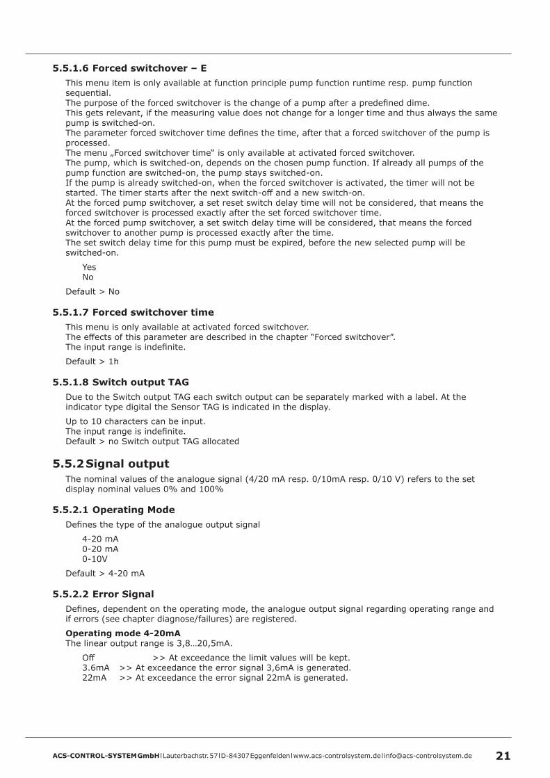
5 .5 .1 .4 .6 Pump function sequential S1/S2/S3/S4
Purpose of the pump function sequential is the alternating use of multiple pumps for the same task (Overflow protection or dry running protection).Due using the pumps for the same task, it can be detected by the pump switch-on time, if one of the pumps doesn’t operate with the necessary performance (Runtime of the pump increases).
All switch outputs, which are activated for pump function, are not assigned to a certain switch point, but should be switched-on resp. switched-off alternating. When reaching the switch delay value, the evaluation device chooses the switch output, which is next in the alternating row.When reaching the reset switch point, the switch outputs are switched-off in the same order like they have been switched-on.The order is predefined. It starts with the switch output with the lowest index. The next switch output is the switch output with the next higher index. After the switch output with the highest index it will be changed to the switch output with the lowest index, e.g. S1…S2…S3…S4…S1…S2….The order is valid for all switch outputs, which corresponds to the pump function.
The index of the last switched-on switch output will not be saved, that means that after power-on it will be started always with the switch output with the lowest index.In the case, that multiple pumps are operated alternating in the same range, the switch points resp. reset switch points must be set to the same value.Due to this, all switch outputs will switch always together. To achieve still the required switch behaviour, one switch output must be set to the needed switch point resp. reset switch point. All other switch outputs must be set to switch points resp. reset switch points, which will never be achieved in standard operation.
In the menu Operating Mode, the working principle of the switch output can be inverted.
5 .5 .1 .5 Operating Mode – EThe operating mode defines the function direction of the switch output, dependent on the function.The effects of this parameter are described in the respective sub-chapter of the chapter „Function“.
ACS-CONTROL-SYSTEM GmbH l Lauterbachstr. 57 l D-84307 Eggenfelden l www.acs-controlsystem.de l [email protected] 21
5 .5 .1 .6 Forced switchover – EThis menu item is only available at function principle pump function runtime resp. pump function sequential.The purpose of the forced switchover is the change of a pump after a predefined dime.This gets relevant, if the measuring value does not change for a longer time and thus always the same pump is switched-on.The parameter forced switchover time defines the time, after that a forced switchover of the pump is processed.The menu „Forced switchover time“ is only available at activated forced switchover.The pump, which is switched-on, depends on the chosen pump function. If already all pumps of the pump function are switched-on, the pump stays switched-on.If the pump is already switched-on, when the forced switchover is activated, the timer will not be started. The timer starts after the next switch-off and a new switch-on.At the forced pump switchover, a set reset switch delay time will not be considered, that means the forced switchover is processed exactly after the set forced switchover time.At the forced pump switchover, a set switch delay time will be considered, that means the forced switchover to another pump is processed exactly after the time. The set switch delay time for this pump must be expired, before the new selected pump will be switched-on.
YesNo
Default > No
5 .5 .1 .7 Forced switchover timeThis menu is only available at activated forced switchover.The effects of this parameter are described in the chapter “Forced switchover”.The input range is indefinite.
Default > 1h
5 .5 .1 .8 Switch output TAGDue to the Switch output TAG each switch output can be separately marked with a label. At the indicator type digital the Sensor TAG is indicated in the display.
Up to 10 characters can be input.The input range is indefinite.Default > no Switch output TAG allocated
5 .5 .2 Signal outputThe nominal values of the analogue signal (4/20 mA resp. 0/10mA resp. 0/10 V) refers to the set display nominal values 0% and 100%
5 .5 .2 .1 Operating ModeDefines the type of the analogue output signal
4-20 mA0-20 mA0-10V
Default > 4-20 mA
5 .5 .2 .2 Error SignalDefines, dependent on the operating mode, the analogue output signal regarding operating range and if errors (see chapter diagnose/failures) are registered.
Operating mode 4-20mAThe linear output range is 3,8…20,5mA.
Off >> At exceedance the limit values will be kept.3.6mA >> At exceedance the error signal 3,6mA is generated.22mA >> At exceedance the error signal 22mA is generated.
ACS-CONTROL-SYSTEM GmbH l Lauterbachstr. 57 l D-84307 Eggenfelden l www.acs-controlsystem.de l [email protected]
Operating mode 0-20mAThe linear output range is 0…20,5mA.
Off >> At exceedance the limit values will be kept.0mA >> At exceedance the error signal 0mA is generated.22mA >> At exceedance the error signal 22mA is generated.
Operating mode 0-10VThe linear output range is 0…10,5V.
Off >> At exceedance the limit values will be kept.0V >> At exceedance the error signal 0V is generated.11V >> At exceedance the error signal 11V is generated.
Default > Off
5 .5 .2 .3 Invert SignalInverts, dependent on the operating mode, the analogue output signal.
4-20 mA >> 20-4 mA0-20 mA >> 20-0 mA0-10 V >> 10-0 V
Default > No
5 .5 .2 .4 SourceDefines the source for the generation of the signal output. For the source, it can be chosen between the measuring value before (%) or after (Lin %) an optionally set linearization.This allows e.g. the output of a linear filling level at the signal output, whereas a linearized volume is shown at the display.
Lin %%
Default > Lin %
ACS-CONTROL-SYSTEM GmbH l Lauterbachstr. 57 l D-84307 Eggenfelden l www.acs-controlsystem.de l [email protected] 23
5 .6 Basic settingThe symbol E at a menu item indicates its position in the extended menu structure.This extended menu structure can be shown in the submenu display by the menu item menu structure.
5 .6 .1 Operating modeDefinition for the use of the device for pressure or level measurement.The change of the setting erases an eventual min/max-adjustment.The change from pressure to level set the primary unit to m.The change from level to pressure set the primary unit to bar.In the Operating Mode Level the input of a material density (menu “Density”) is available.
PressureLevel
Default > Pressure
5 .6 .2 Primary UnitThe primary unit defines the internal reference unit of the measuring signal.At the change of the primary unit an automatic conversion is calculated.At the change of the primary unit from a pressure unit to a height unit the gravitational acceleration mean value 9,81 m/s2 is used.For special applications another value can be stored by factory.
bar / mbar / m / cm / mm / feet / inch
Default > bar
ACS-CONTROL-SYSTEM GmbH l Lauterbachstr. 57 l D-84307 Eggenfelden l www.acs-controlsystem.de l [email protected]
5 .6 .3 Min/Max-AdjustmentThe min/max-adjustment set the measuring range limits.2 points are defined, that set the ratio of the measured pressure/level and the measuring range of the device.The current measuring value is indicated in the display.The input of the measuring range limits 0% and 100% are not mandatory. Values within the measuring range e.g. 11% and 87% can be also input. In this case there is an automatic calculation to 0% resp. 100%. The higher the difference between these points, the more precise is the following calculation.The min/max-adjustment is relevant for linearization, signal output and display scaling.
Lower adjustment valueUpper adjustment value
The input range is indefinite.Default > Lower calibrated measuring value = 0% / Upper calibrated measuring value = 100%
5 .6 .4 Limit min/max – EIf the measuring value exceeds the limits of the Min/Max-Adjustment, these limits are kept at activated function. An exceedance is not possible.At deactive function measurement values besides the limit values are output.This function is especially useful at a flow measurement to avoid negative flow measuring values.
deactiveactive
Default > deactive
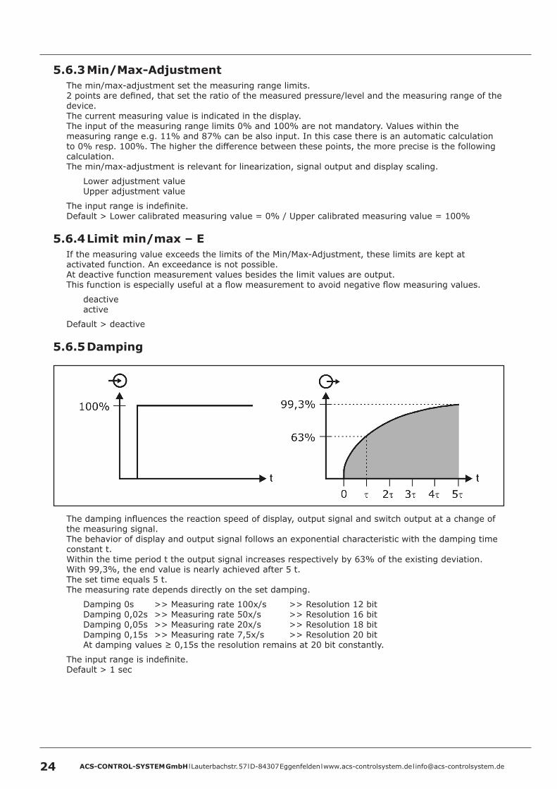
5 .6 .5 Damping
The damping influences the reaction speed of display, output signal and switch output at a change of the measuring signal.The behavior of display and output signal follows an exponential characteristic with the damping time constant t.Within the time period t the output signal increases respectively by 63% of the existing deviation.With 99,3%, the end value is nearly achieved after 5 t.The set time equals 5 t.The measuring rate depends directly on the set damping.
Damping 0s >> Measuring rate 100x/s >> Resolution 12 bitDamping 0,02s >> Measuring rate 50x/s >> Resolution 16 bitDamping 0,05s >> Measuring rate 20x/s >> Resolution 18 bitDamping 0,15s >> Measuring rate 7,5x/s >> Resolution 20 bitAt damping values ≥ 0,15s the resolution remains at 20 bit constantly.
The input range is indefinite.Default > 1 sec
ACS-CONTROL-SYSTEM GmbH l Lauterbachstr. 57 l D-84307 Eggenfelden l www.acs-controlsystem.de l [email protected] 25
5 .6 .6 Density – EThis menu item is only available at operation mode level.The density represents a material constant of the measured process material.For the conversion of a pressure into a height besides the gravitational acceleration the density of the process material is also relevant for the calculation result.
h = p / (ρ * g)h >> Height (Level)p >> Pressureρ >> Densityg >> Gravitational acceleration value (9,81 m/s2)
The input range is indefinite.Default > 1 kg/dm3
5 .6 .7 Position Adjustment – EBy the use of the position adjustment measuring errors caused by the installation position can be corrected.This errors can be caused e.g. by the dead weight of the measuring membrane or by a higher process temperature.The position adjustment must be done in installed position at conditions, that are representative for the measuring task and should only be done in an absolutely pressure less condition, cause the set primary unit and a density value are not regarded in this function.For the suppression of a measuring signal, which is caused by the process material, the function offset adjustment is available.In the sub menu offset, a value can be input, that is added to the current measuring value or in the sub menu enter nominal value, a value can be input, which equals the current measuring signal.
OffsetCurrent measuring value -0.090 bar > Offset 0.090 bar > resulting measuring value 0.000 bar
The input range is indefinite.
Enter nominal valueCurrent measuring value -0.090 bar > Nominal Value 0.000 bar > resulting measuring value 0.000 bar
The input range is indefinite.
Default > Offset = 0
5 .6 .8 Offset Adjustment – EBy the use of the offset adjustment, a constant value can be added to the measuring value, e.g. to suppress overlayed measuring signals in a pressure biased system. For the suppressing of measuring deviations, caused by the installation position, the function position adjustment ist available.Position adjustment and offset adjustment are identical, is primary unit and density are not altered compared to the default values.In the sub menu offset, a value can be input, that is added to the current measuring value or in the sub menu enter nominal value, a value can be input, which equals the current measuring signal.
OffsetCurrent measuring value -0.090 bar > Offset 0.090 bar > resulting measuring value 0.000 bar
The input range is indefinite.
Enter nominal valueCurrent measuring value -0.090 bar > Nominal Value 0.000 bar > resulting measuring value 0.000 bar
The input range is indefinite.
Default > Offset = 0
ACS-CONTROL-SYSTEM GmbH l Lauterbachstr. 57 l D-84307 Eggenfelden l www.acs-controlsystem.de l [email protected]
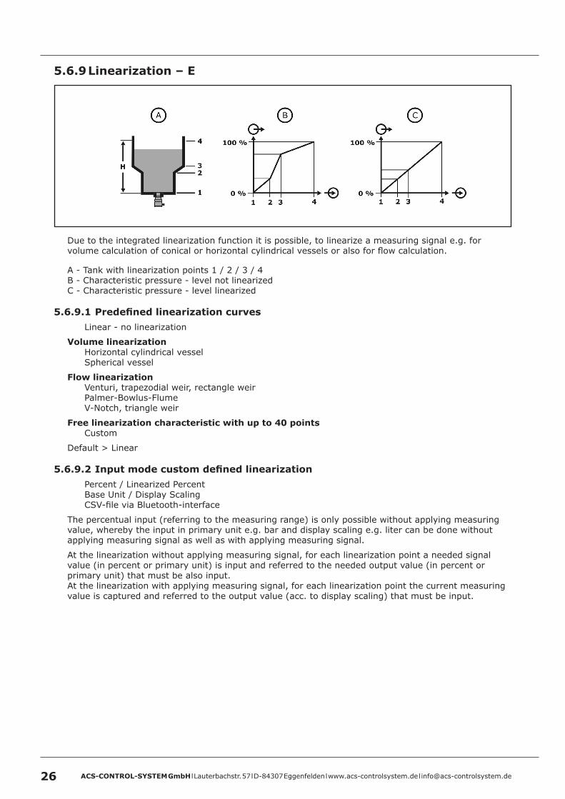
5 .6 .9 Linearization – E
Due to the integrated linearization function it is possible, to linearize a measuring signal e.g. for volume calculation of conical or horizontal cylindrical vessels or also for flow calculation.
A - Tank with linearization points 1 / 2 / 3 / 4B - Characteristic pressure - level not linearizedC - Characteristic pressure - level linearized
5 .6 .9 .1 Predefined linearization curvesLinear - no linearization
Volume linearizationHorizontal cylindrical vesselSpherical vessel
Flow linearizationVenturi, trapezodial weir, rectangle weirPalmer-Bowlus-FlumeV-Notch, triangle weir
Free linearization characteristic with up to 40 pointsCustom
Default > Linear
5 .6 .9 .2 Input mode custom defined linearizationPercent / Linearized PercentBase Unit / Display ScalingCSV-file via Bluetooth-interface
The percentual input (referring to the measuring range) is only possible without applying measuring value, whereby the input in primary unit e.g. bar and display scaling e.g. liter can be done without applying measuring signal as well as with applying measuring signal.
At the linearization without applying measuring signal, for each linearization point a needed signal value (in percent or primary unit) is input and referred to the needed output value (in percent or primary unit) that must be also input.At the linearization with applying measuring signal, for each linearization point the current measuring value is captured and referred to the output value (acc. to display scaling) that must be input.
ACS-CONTROL-SYSTEM GmbH l Lauterbachstr. 57 l D-84307 Eggenfelden l www.acs-controlsystem.de l [email protected] 27
Linearization PointsThe number of linearization points for the complete measuring characteristic must be defined.
The input range is limited to values from 2 to 40.Default > 2
LinearizationAt the input mode percent / linearized percent the input signal refers percentual to the measuring range, that is defined at the min./max. adjustment for 0% and 100%. The output signal must also be considered percentual.At the input mode primary unit / display scaling the input signal refers to the input signal in the primary unit. The output signal refers to the display range (primary unit or scaled), that is defined in the display scaling.The complete characteristic, eventually also the measuring range end values 0% and 100% must be defined, cause the measuring range end values from the min./max. adjustment are not copied into the linearization table.
The input range is indefinite.Default > Linearization point 1 > 0.000% = 0.000% resp. 0.000bar / Linearization point 2 > 100.000% = 100.000% resp. 1.000bar
StoreInput linearization points are not automatically stored loss-protected.To store one or also more linearization points loss-protected, the function store must be executed.
5 .6 .10 Sensor TAGDue to the Sensor TAG different devices can be differentiated. At the indicator type digital the Sensor TAG is indicated in the display.The Sensor TAG is added automatically to the Bluetooth-name, to allow the device identification when using multiple devices in reception range.
Up to 19 characters can be input.The input range is indefinite.Default > no Sensor TAG allocated
5 .6 .11 Date/TimeInput of date and time. For the measurement value recording, the measurement values are supplied with a time stamp of the integrated real time clock, which includes date and time. The set values are buffered at a short time (see chapter „Technical data“) supply voltage fail, whereas a longer failure resets the values. The values must then be set again.At the battery powered system the values are buffered also at a long term failure of the supply voltage.
The input range is limited to conclusive values for date and time. Default > 01.01.2001 / 00:00:00 resp. current date / current time
5 .6 .12 Factory ResetThe factory reset changes all settings to default values.The factory reset does not concern:
Diagnose dataHistorical measuring dataStorage intervalCustom defined linearization
ACS-CONTROL-SYSTEM GmbH l Lauterbachstr. 57 l D-84307 Eggenfelden l www.acs-controlsystem.de l [email protected]
5 .7 DisplayThe symbol E at a menu item indicates its position in the extended menu structure.This extended menu structure can be shown in the submenu display by the menu item menu structure.
5 .7 .1 Indicator valueThe measuring value can be alternatively displayed in the set primary unit e.g. bar or meter, or with any desired scaling referring percentual to the measuring range. The indication in primary unit is only possible with linearization linear.
Primary UnitScaled
The input range is indefinite.Default > Primary Unit
ACS-CONTROL-SYSTEM GmbH l Lauterbachstr. 57 l D-84307 Eggenfelden l www.acs-controlsystem.de l [email protected] 29
5 .7 .2 ScalingThis menu item is only available at indicator value scaled.By defining a scaling the measuring range can be rescaled into any desired numerical range. This allows e.g. the indication of the volume in liter.The current measuring value is indicated in the display.The input of the measuring range limits 0% and 100% are not mandatory. Values within the measuring range e.g. 11% and 87% can be also input. In this case there is an automatic calculation to 0% resp. 100%.
Lower display valueUpper display value
The input range is indefinite.Default > Measuring value 0.000% = Display 0.000 / Measuring value 100.000% = Display 1.000
5 .7 .3 UnitThis menu item is only available at indicator value scaledIf a scaled indicator value is used, additionally an unit can be selected, that is indicated in the display (not at indicator type vertical bargraph).The unit is only indicated as text and is not included into calculations.There are multiple predefined units in different categories available.
Masskg / t / lb
Volumel / hl / m3 / in3 / gal / ft3
Heightmm / cm / m / in / ft
Pressurembar / bar / Pa / kPa / MPa / Psi / Torr / mmH2O
Flowl/s / l/min / l/h / m3/s / m3/min / m3/h / lb/s / gal/s
Custom definedUp to 10 characters can be input.The input range is indefinite.Default > no text allocated
5 .7 .4 Fractional Digits – EThe measuring value can be formatted by the use of fractional digits.Is the indication of the measuring value with the current fractional digits number not possible, a change to the correct fractional digits number is executed automatically.
The input range is limited to values from 0 to 3.Default > 3
ACS-CONTROL-SYSTEM GmbH l Lauterbachstr. 57 l D-84307 Eggenfelden l www.acs-controlsystem.de l [email protected]
5 .7 .5 Indicator TypeDependent on the requirements the measuring values can be indicated in different types.
Digital
Switch points, active or deactiveSensor TAGDigital measuring valueUnitQuantity counter value (only at activated function quantity counter)Horizontal scaled bargraphMark of switch points at the bargraph
Manometer
Round pointer scaleMark of the switch points at the pointer scaleUnitDigital measuring value
Bargraph
Digital measuring valueUnitHorizontal scaled bargraph
ACS-CONTROL-SYSTEM GmbH l Lauterbachstr. 57 l D-84307 Eggenfelden l www.acs-controlsystem.de l [email protected] 31
Vertical Bargraph
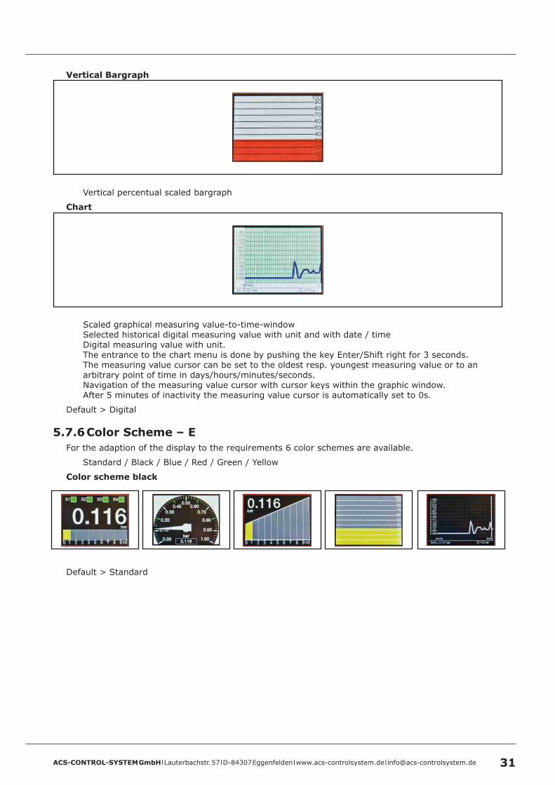
Vertical percentual scaled bargraph
Chart
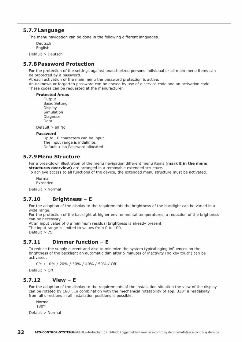
Scaled graphical measuring value-to-time-windowSelected historical digital measuring value with unit and with date / timeDigital measuring value with unit.The entrance to the chart menu is done by pushing the key Enter/Shift right for 3 seconds.The measuring value cursor can be set to the oldest resp. youngest measuring value or to an arbitrary point of time in days/hours/minutes/seconds.Navigation of the measuring value cursor with cursor keys within the graphic window.After 5 minutes of inactivity the measuring value cursor is automatically set to 0s.
Default > Digital
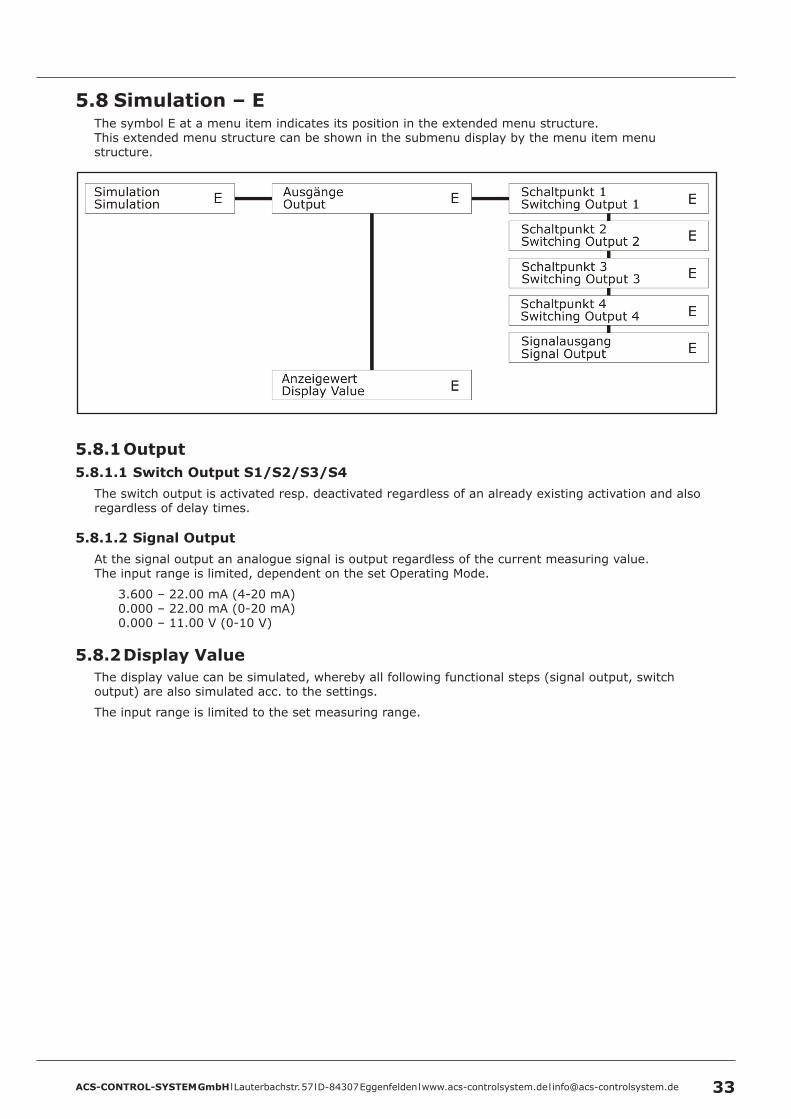
5 .7 .6 Color Scheme – EFor the adaption of the display to the requirements 6 color schemes are available.
Standard / Black / Blue / Red / Green / Yellow
Color scheme black
Default > Standard
ACS-CONTROL-SYSTEM GmbH l Lauterbachstr. 57 l D-84307 Eggenfelden l www.acs-controlsystem.de l [email protected]
5 .7 .7 LanguageThe menu navigation can be done in the following different languages.
DeutschEnglish
Default > Deutsch
5 .7 .8 Password ProtectionFor the protection of the settings against unauthorized persons individual or all main menu items can be protected by a password.At each activation of the main menu the password protection is active.An unknown or forgotten password can be erased by use of a service code and an activation code. These codes can be requested at the manufacturer.
Protected AreasOutputBasic SettingDisplaySimulationDiagnoseData
Default > all No
PasswordUp to 10 characters can be input.The input range is indefinite.Default > no Password allocated
5 .7 .9 Menu StructureFor a breakdown illustration of the menu navigation different menu items (mark E in the menu structures overview) are arranged in a removable extended structure.To achieve access to all functions of the device, the extended menu structure must be activated.
NormalExtended
Default > Normal
5 .7 .10 Brightness – EFor the adaption of the display to the requirements the brightness of the backlight can be varied in a wide range.For the protection of the backlight at higher environmental temperatures, a reduction of the brightness can be necessary.At an input value of 0 a minimum residual brightness is already present.The input range is limited to values from 0 to 100.Default > 75
5 .7 .11 Dimmer function – ETo reduce the supply current and also to minimize the system typical aging influences on the brightness of the backlight an automatic dim after 5 minutes of inactivity (no key touch) can be activated.
0% / 10% / 20% / 30% / 40% / 50% / Off
Default > Off
5 .7 .12 View – EFor the adaption of the display to the requirements of the installation situation the view of the display can be rotated by 180°. In combination with the mechanical rotatability of app. 330° a readability from all directions in all installation positions is possible.
Normal180°
Default > Normal
ACS-CONTROL-SYSTEM GmbH l Lauterbachstr. 57 l D-84307 Eggenfelden l www.acs-controlsystem.de l [email protected] 33
5 .8 Simulation – EThe symbol E at a menu item indicates its position in the extended menu structure.This extended menu structure can be shown in the submenu display by the menu item menu structure.
5 .8 .1 Output5 .8 .1 .1 Switch Output S1/S2/S3/S4
The switch output is activated resp. deactivated regardless of an already existing activation and also regardless of delay times.
5 .8 .1 .2 Signal OutputAt the signal output an analogue signal is output regardless of the current measuring value.The input range is limited, dependent on the set Operating Mode.
3.600 – 22.00 mA (4-20 mA)0.000 – 22.00 mA (0-20 mA)0.000 – 11.00 V (0-10 V)
5 .8 .2 Display ValueThe display value can be simulated, whereby all following functional steps (signal output, switch output) are also simulated acc. to the settings.
The input range is limited to the set measuring range.
ACS-CONTROL-SYSTEM GmbH l Lauterbachstr. 57 l D-84307 Eggenfelden l www.acs-controlsystem.de l [email protected]
5 .9 Diagnosis
5 .9 .1 Switching Outputs5 .9 .1 .1 Operation Cycles S1/S2/S3/S4
The number of operation cycles per switch output is indicated.An operation cycle is a complete change of the switch state till back to the start state, thus deactive - active - deactive.
5 .9 .1 .2 Runtime S1/S2/S3/S4The runtime per switch output is indicated.The runtime of each switch output can be reset here separately.At the pump function runtime, this is especially necessary after a pump exchange, to include the new pump into the runtime dependent activation.
5 .9 .2 FailureThe device registers multiple of short time or also continuous existing functional failures in type and frequency of occurrence.
Overpressureexceeding the nominal measuring range by 3%
Underpressureexceeding the nominal measuring range by 3%
Over Rangeexceeding the signal output range (dependent on Operating Mode)
20.5 mA (4-20 mA)20.5 mA (0-20 mA)10.5 V (0-10 V)
ACS-CONTROL-SYSTEM GmbH l Lauterbachstr. 57 l D-84307 Eggenfelden l www.acs-controlsystem.de l [email protected] 35
Under Rangeexceeding the signal output range (dependent on Operating Mode)
3.8 mA (4-20 mA)-0.4 mA (0-20 mA) – theoretical value-0.5 V (0-10 V) – theoretical value
Sig . out breakwire break at signal output on signal output not connected at Operating Mode 4-20 mA resp. 0-20 mA
5 .9 .3 Error MessagesThe type of failure, that leads to the device reactions
Indication on displayError signal at analogue output, depending on selected operating modeError function at switching output, depending on settings
can be selected.
The following failures can be selected:
Overpressureexceeding the nominal measuring range by 3%
Underpressureexceeding the nominal measuring range by 3%
Output overflowOvershoot of the analogue output range depending on selected operating mode
Operating mode 4-20mA >> 21mAOperating mode 0-20mA >> 21mAOperating mode 0-10V >> 10,5V
Default > activated
Output underflowUndershoot of the analogue output range depending on selected operating mode
Operating mode 4-20mA >> 3,8mAOperating mode 0-20mA >> -0,4mA – theoretical valueOperating mode 0-10V >> -0,5V – theoretical value
Default > activated
Power loss
Default > deactivated
5 .9 .4 Min ./Max . Drag IndicatorThe drag indicator is used for detection and indication of the minimum and maximum registeredmeasuring values.The drag indicator can be separately reset by pushing the key Shift right/Enter.
ACS-CONTROL-SYSTEM GmbH l Lauterbachstr. 57 l D-84307 Eggenfelden l www.acs-controlsystem.de l [email protected]
5 .9 .5 Operating HoursThe operating hours of the device since the last device start-up are detected.The indication is done in hours.
5 .9 .6 Operating Hours totalThe operating hours of the device since the first device start-up are detected.The indication is done in hours.
5 .9 .7 System StartsThe number of the occurred system starts resp. device restarts is registered.
5 .9 .8 Min ./Max . Device TemperatureThe minimum and maximum temperature of the electronic in the area of the terminal enclosure (not the process temperature) is registered.
5 .9 .9 Calibration DateIndication of the date (format DDMMJJ), the calibration by factory is done.
5 .9 .10 Serial NumberIndication of the serial number of the device.
5 .9 .11 InfoIndication of manufacturer data and firmware version
ACS-CONTROL-SYSTEM GmbH l Lauterbachstr. 57 l D-84307 Eggenfelden l www.acs-controlsystem.de l [email protected] 37
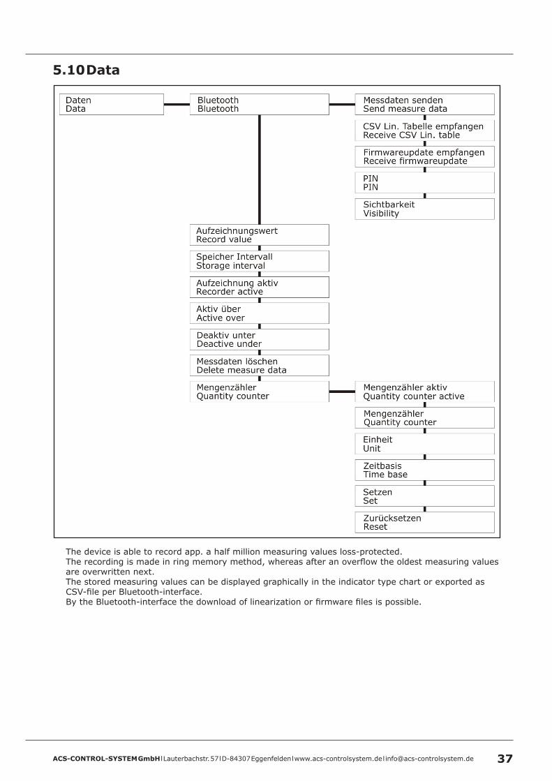
5 .10 Data
The device is able to record app. a half million measuring values loss-protected.The recording is made in ring memory method, whereas after an overflow the oldest measuring values are overwritten next.The stored measuring values can be displayed graphically in the indicator type chart or exported as CSV-file per Bluetooth-interface.By the Bluetooth-interface the download of linearization or firmware files is possible.
ACS-CONTROL-SYSTEM GmbH l Lauterbachstr. 57 l D-84307 Eggenfelden l www.acs-controlsystem.de l [email protected]
5 .10 .1 BluetoothFor the Bluetooth-communication two authentication methods are available.
Unprotected transmissionNo PIN is usedCause the device does only receive/send files only after selection in the menu, this is the most simple and recommended way of transmission.If no PIN is used, each communication is uncoded, but the devices must not connect together.
Protected resp . encoded transmissionA PIN is used.If a PIN is used, the devices must be connected together for a transmission. The procedure differs depending on the end device.A PIN must be input and the visibility must be switched to on.Afterwards the connection can be made at the end device.In the end device the same PIN must be used, that is input in the device.After the file transmission the visibility should be switched to off.Note: For a definite identification of the devices it is recommended to use a Sensor TAG.
5 .10 .1 .1 Send measure dataThe recorded measuring values can be transmitted as a CSV-file to a Bluetooth end device.Alternatively all measuring values or only the measuring values from the measuring value cursor (setting in the chart menu) till to the current measuring value can be transmitted.After the selection end devices with Bluetooth-ability are searched and after selection and approval the measuring values are transmitted.
5 .10 .1 .2 Receive CSV Lin . TableTo simplify enormous linearization procedures directly at the device, it is possible to generate alinearization table as CSV-file and transmit it into the device.There are different tank calculation programs available to calculate the linearization of a tank form comfortably.The CSV-file must match a defined formatting.
Comments can be marked with a leading *.Separator TabDecimal separator dot or comma.First value percentual filling level, second value linearized percent.Table length maximum 40
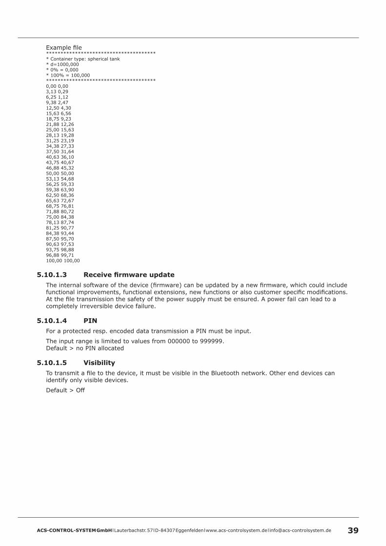
ACS-CONTROL-SYSTEM GmbH l Lauterbachstr. 57 l D-84307 Eggenfelden l www.acs-controlsystem.de l [email protected] 39
Example file*************************************** Container type: spherical tank* d=1000,000* 0% = 0,000* 100% = 100,000**************************************0,00 0,003,13 0,296,25 1,129,38 2,4712,50 4,3015,63 6,5618,75 9,2321,88 12,2625,00 15,6328,13 19,2831,25 23,1934,38 27,3337,50 31,6440,63 36,1043,75 40,6746,88 45,3250,00 50,0053,13 54,6856,25 59,3359,38 63,9062,50 68,3665,63 72,6768,75 76,8171,88 80,7275,00 84,3878,13 87,7481,25 90,7784,38 93,4487,50 95,7090,63 97,5393,75 98,8896,88 99,71100,00 100,00
5 .10 .1 .3 Receive firmware updateThe internal software of the device (firmware) can be updated by a new firmware, which could include functional improvements, functional extensions, new functions or also customer specific modifications.At the file transmission the safety of the power supply must be ensured. A power fail can lead to a completely irreversible device failure.
5 .10 .1 .4 PINFor a protected resp. encoded data transmission a PIN must be input.
The input range is limited to values from 000000 to 999999.Default > no PIN allocated
5 .10 .1 .5 VisibilityTo transmit a file to the device, it must be visible in the Bluetooth network. Other end devices can identify only visible devices.
Default > Off
ACS-CONTROL-SYSTEM GmbH l Lauterbachstr. 57 l D-84307 Eggenfelden l www.acs-controlsystem.de l [email protected]
5 .10 .2 Record valueThe measuring value can be alternatively recorded with primary unit or with any desired scaling referring percentual to the measuring range.
Primary unitScaled
Default > Primary unit
5 .10 .3 Storage intervalThe storage interval defines the time interval between two measuring values, which should be stored in the measuring value memory.
The input range is limited to values from 1 to 99999.Default > 60 s
5 .10 .4 Activation RecordingTo start the recording of measuring values, this must be activated.
AlwaysEach measuring value will be stored at the set storage interval.
DeactiveThe measuring value recording is switched off.
Threshold valueThe measuring value recording at the set storage interval will be switched on at overrun of the set threshold value (menu „Active over“) resp. switched off at underrun of the set threshold value (menu „Deactive under“)
The input range is limited to values from 1 to 99999.Default > 0.000
Default > Deactive
5 .10 .5 Delete measure dataAll existing stored measuring values in the measuring value memory are erased.
ACS-CONTROL-SYSTEM GmbH l Lauterbachstr. 57 l D-84307 Eggenfelden l www.acs-controlsystem.de l [email protected] 41
5 .10 .6 Quantity counterThe quantity counter integrates the calculated measuring values from the display scaling by the time. These values are stored every second.If the eventually activated impulse output cant output all impulses time conformal due to a too high frequency, all impulses are output afterwards until all accumulated impulses could be output, also if the flow is already lower or has stopped. Thus the amount of output pulses fits always to the quantity counter. Nevertheless this should be avoided from the first by a correct setting.
Quantity counter active
YesNo
Default > No
Quantity counter
The current quantity counter value, which is calculated at the moment of entering the menu, is displayed. This value can be actualized by the keys Up or Down.
Unit
Volumel / hl / m3 / in3 / gal / ft3
User definedUp to 10 characters can be input.The input range is indefinite.Default > no text allocated
Time base
HoursMinutesSeconds
Default > Hours
Set
The value of the quantity counter can be preset to an arbitrary value.
The input range corresponds with the settings of the display scaling.Default > 0
Reset
The quantity counter value is reset to 0.
ACS-CONTROL-SYSTEM GmbH l Lauterbachstr. 57 l D-84307 Eggenfelden l www.acs-controlsystem.de l [email protected]
5 .11 Start-up procedure5 .11 .1 Pressure measurement
The sensor is preconfigured to pressure measurement dependent on the pressure range alternatively in unit mbar or bar by factory.Only a few changings must be optionally made.
Sub menu Basic Setting
Position AdjustmentPrimary UnitMin/Max Adjustment (when using the signal output)
ACS-CONTROL-SYSTEM GmbH l Lauterbachstr. 57 l D-84307 Eggenfelden l www.acs-controlsystem.de l [email protected] 43
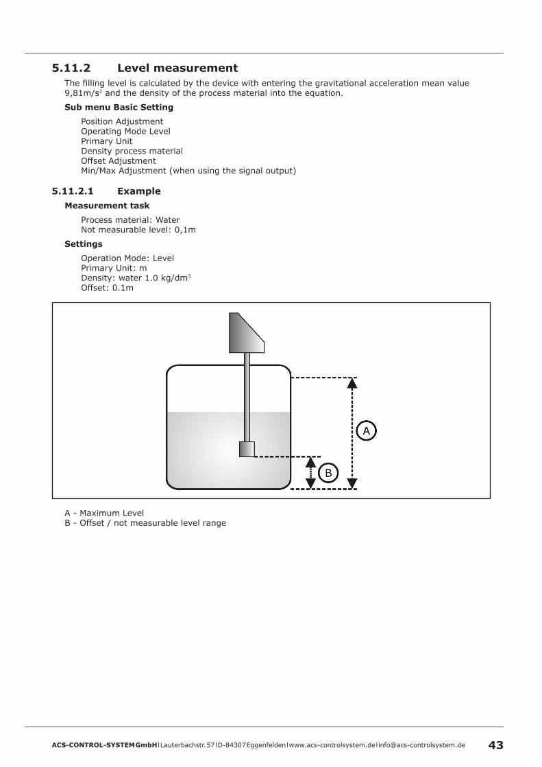
5 .11 .2 Level measurementThe filling level is calculated by the device with entering the gravitational acceleration mean value 9,81m/s2 and the density of the process material into the equation.
Sub menu Basic Setting
Position AdjustmentOperating Mode LevelPrimary UnitDensity process materialOffset AdjustmentMin/Max Adjustment (when using the signal output)
5 .11 .2 .1 ExampleMeasurement task
Process material: WaterNot measurable level: 0,1m
Settings
Operation Mode: LevelPrimary Unit: mDensity: water 1.0 kg/dm3
Offset: 0.1m
A - Maximum LevelB - Offset / not measurable level range
ACS-CONTROL-SYSTEM GmbH l Lauterbachstr. 57 l D-84307 Eggenfelden l www.acs-controlsystem.de l [email protected]
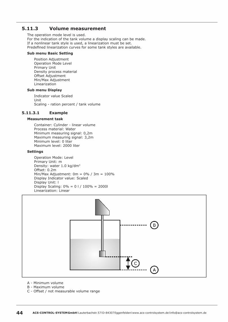
5 .11 .3 Volume measurementThe operation mode level is used.For the indication of the tank volume a display scaling can be made.If a nonlinear tank style is used, a linearization must be set.Predefined linearization curves for some tank styles are available.
Sub menu Basic Setting
Position AdjustmentOperation Mode LevelPrimary UnitDensity process materialOffset AdjustmentMin/Max AdjustmentLinearization
Sub menu Display
Indicator value ScaledUnitScaling - ration percent / tank volume
5 .11 .3 .1 ExampleMeasurement task
Container: Cylinder - linear volumeProcess material: WaterMinimum measuring signal: 0,2mMaximum measuring signal: 3,2mMinimum level: 0 literMaximum level: 2000 liter
Settings
Operation Mode: LevelPrimary Unit: mDensity: water 1.0 kg/dm3
Offset: 0.2mMin/Max Adjustment: 0m = 0% / 3m = 100%Display Indicator value: ScaledDisplay Unit: lDisplay Scaling: 0% = 0 l / 100% = 2000lLinearization: Linear
A - Minimum volumeB - Maximum volumeC - Offset / not measurable volume range
ACS-CONTROL-SYSTEM GmbH l Lauterbachstr. 57 l D-84307 Eggenfelden l www.acs-controlsystem.de l [email protected] 45
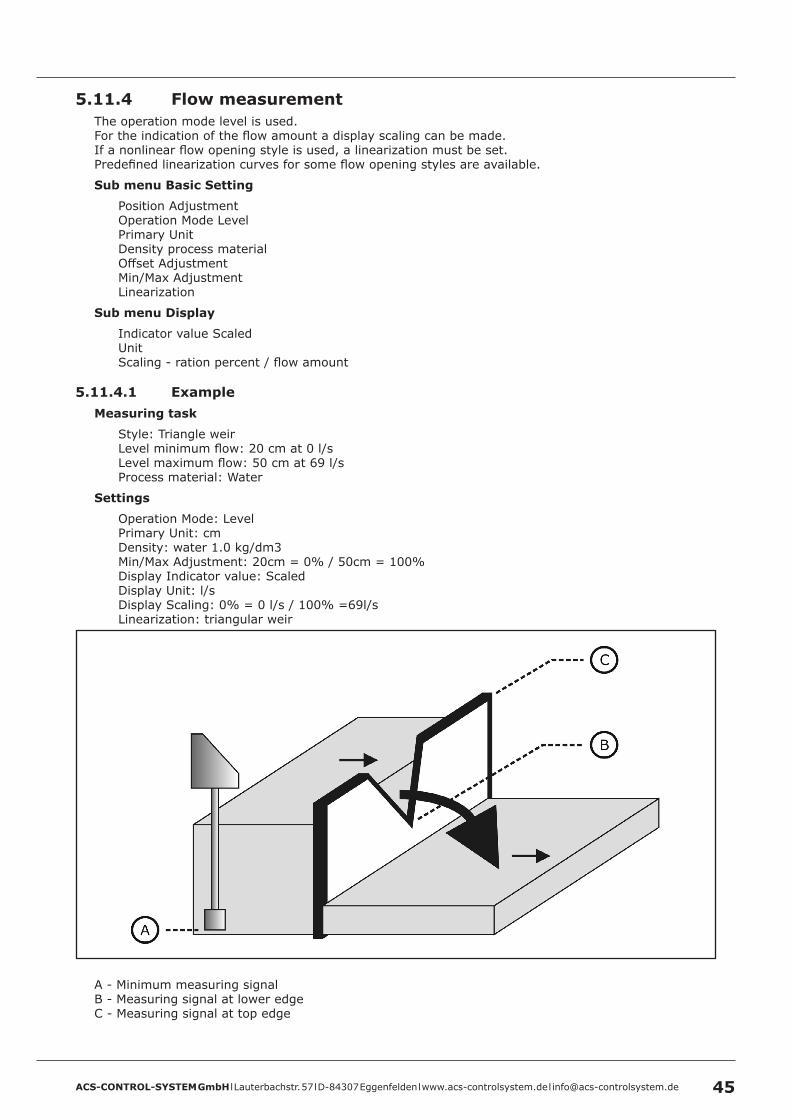
5 .11 .4 Flow measurementThe operation mode level is used.For the indication of the flow amount a display scaling can be made.If a nonlinear flow opening style is used, a linearization must be set.Predefined linearization curves for some flow opening styles are available.
Sub menu Basic Setting
Position AdjustmentOperation Mode LevelPrimary UnitDensity process materialOffset AdjustmentMin/Max AdjustmentLinearization
Sub menu Display
Indicator value ScaledUnitScaling - ration percent / flow amount
5 .11 .4 .1 ExampleMeasuring task
Style: Triangle weirLevel minimum flow: 20 cm at 0 l/sLevel maximum flow: 50 cm at 69 l/sProcess material: Water
Settings
Operation Mode: LevelPrimary Unit: cmDensity: water 1.0 kg/dm3Min/Max Adjustment: 20cm = 0% / 50cm = 100%Display Indicator value: ScaledDisplay Unit: l/sDisplay Scaling: 0% = 0 l/s / 100% =69l/sLinearization: triangular weir
A - Minimum measuring signalB - Measuring signal at lower edgeC - Measuring signal at top edge

ACS-CONTROL-SYSTEM GmbH l Lauterbachstr. 57 l D-84307 Eggenfelden l www.acs-controlsystem.de l [email protected]
5 .12 Software historyVersion Date Modifications
4.1.0 07/2017 Original version
ACS-CONTROL-SYSTEM GmbH l Lauterbachstr. 57 l D-84307 Eggenfelden l www.acs-controlsystem.de l [email protected] 47
6 Service6 .1 Maintenance
The device is free of maintenance.
Special substances can lead to solid coatings on the sensor. Seized depositions can lead to faulty measurement results.
In the case of coat forming liquids the sensor must be regularly cleaned e.g. with clear water. Don’t use sharp resp. hard tools or aggressive chemicals for cleaning.
6 .2 DismountingAttention – Risk of burns!Let the device cool down sufficiently fore dismounting itDuring dismounting there is a risk of dangerously hot media escaping.
Attention – Risk of injury!Dismount the device only when the system is pressureless.During dismounting there is a risk of fast escaping media resp. pressure blow.
6 .3 RepairA repair may only be carried out by the manufacturer.
If the device is sent back for repair, the following information’s must be enclosed:• An exact description of the application.• The chemical and physical characteristics of the product.• A short description of the occurred error.
6 .4 ReturnBefore returning the device, the following measures must be performed:
• All adhesive product residues must be removed. This is especially important, if the product is unhealthily, e.g. caustic, toxic, carcinogenic, radioactive etc.
• A returning must be refrained, if it is not possible by 100% to remove the unhealthily product completely, because e.g. it is penetrate into cracks or is diffused through plastic.
6 .5 DisposalDispose of instrument components and packaging materials in an environmentally compatible way and in accordance with the country-specific waste disposal regulations.
This instrument is not subject to the WEEE directive and the respective national laws. Hence, pass the instrument directly on to a specialized recycling company and do not use the municipal collecting points. These may be used only for privately used products according to the WEEE directive.
ACS-CONTROL-SYSTEM GmbH l Lauterbachstr. 57 l D-84307 Eggenfelden l www.acs-controlsystem.de l [email protected]
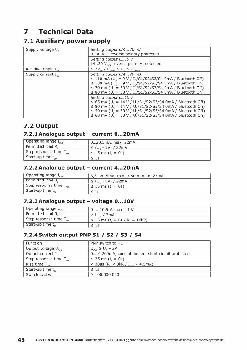
7 Technical Data7 .1 Auxiliary power supplySupply voltage US Setting output 0/4...20 mA
9..30 VDC, reverse polarity protectedSetting output 0…10 V14..30 VDC, reverse polarity protected
Residual ripple UPP ≤ 2VPP / USmin ≤ US ≤ USmax
Supply current IIn Setting output 0/4...20 mA≤ 110 mA (US = 9 V / IO/S1/S2/S3/S4 0mA / Bluetooth Off)≤ 130 mA (US = 9 V / IO/S1/S2/S3/S4 0mA / Bluetooth On)≤ 70 mA (US = 30 V / IO/S1/S2/S3/S4 0mA / Bluetooth Off)≤ 80 mA (US = 30 V / IO/S1/S2/S3/S4 0mA / Bluetooth On)Setting output 0…10 V≤ 65 mA (US = 14 V / UO/S1/S2/S3/S4 0mA / Bluetooth Off)≤ 80 mA (US = 14 V / UO/S1/S2/S3/S4 0mA / Bluetooth On)≤ 50 mA (US = 30 V / UO/S1/S2/S3/S4 0mA / Bluetooth Off)≤ 60 mA (US = 30 V / UO/S1/S2/S3/S4 0mA / Bluetooth On)
7 .2 Output7 .2 .1 Analogue output – current 0…20mAOperating range IOut 0…20,5mA, max. 22mAPermitted load RL ≤ (US - 9V) / 22mAStep response time T90 ≤ 15 ms (td = 0s)Start-up time tOn ≤ 1s
7 .2 .2 Analogue output – current 4…20mAOperating range IOut 3,8…20,5mA, min. 3,6mA, max. 22mAPermitted load RL ≤ (US - 9V) / 22mAStep response time T90 ≤ 15 ms (td = 0s)Start-up time tOn ≤ 1s
7 .2 .3 Analogue output – voltage 0…10VOperating range UOut 0 ... 10,5 V, max. 11 VPermitted load RL ≥ UOut / 3mAStep response time T90 ≤ 15 ms (td = 0s / RL = 10kR)Start-up time tOn ≤ 1s
7 .2 .4 Switch output PNP S1 / S2 / S3 / S4Function PNP switch to +LOutput voltage UOut UOut ≥ US – 2VOutput current IL 0… ≤ 200mA, current limited, short circuit protectedStep response time T90 ≤ 25 ms (td = 0s)Rise time T90 < 30µs (RL < 3kR / IOut > 4,5mA)Start-up time tOn ≤ 1sSwitch cycles ≥ 100.000.000
ACS-CONTROL-SYSTEM GmbH l Lauterbachstr. 57 l D-84307 Eggenfelden l www.acs-controlsystem.de l [email protected] 49
7 .3 Measuring accuracyReference conditions EN/IEC 60770-1
Environmental temperature 15…25°CEnvironmental air pressure 860..1060kPaAir humidity 45...75% r.F.Warm-up time tOn 240sSupply voltage US 24VDC ±0,1VCalibration position Vertical
Process connection bottom
Characteristic deviation 3) 5) 6) 12) ≤ ±0,15% / ±0,5% FS 2)
Nonlinearity 6) 12) ≤ ±0,05% / ±0,35% FS 2)
Hysteresis 6) 12) ≤ ±0,1% FS 2)
Repeatability 6) 12) ≤ ±0,05% FS 2)
Influence of supply voltage Setting output 0/4...20 mA≤ ±0,001% FS 2) / VSetting output 0…10 V≤ ±0,006% FS 2) / V
Load influence Setting output 0/4...20 mA≤ ±0,01% FS 2) / 100RSetting output 0…10 V≤ ±0,05% FS 2) / 1mA
Long term drift 6) 12) ≤ ±0,2% FS 2) / yearTemperature deviation 6) 12) Tk
4) Zero / Tk 4) Span
Measuring range ≤ 25 bar≤ ±0,02% FS 2) / K (0…+80°C)≤ ±0,03% FS 2) / K (-40…0°C / +80…+125°C)Tk
4) Zero / Tk 4) Span
Measuring range ≥ 40 bar≤ ±0,02% FS 2) / K (-40…+100°C)≤ ±0,03% FS 2) / K (+100…+125°C)
Mounting position deviation 10) ≤ 4 mbarProcess connection type 5 – Thread G1“, front-flush≤ 10 mbar
2) Referring to nominal measuring span resp. full scale (FS)3) Nonlinearity + Hysteresis + Reproducibility4) Tk = Temperature coefficient5) Limit value adjustment acc. to EN/IEC 60770-16) Specification for TD 7) = 1 (adjusted measuring range = nominal measuring range). Specification for TD 7) ≥ 1 (adjusted measuring range ≤ nominal measuring range) = specification at nominal measuring range x TD 7)
7) Turn-Down TD = nominal measuring range (FS 2)) / adjusted measuring range)10) Device rotated by 180°, process connection upside12) Higher values for special measuring range
7 .4 ClockCycle accuracy ≤ ±1 minute / monthBattery run time ≥ 10 yearsHold-up timebattery-free system
≥ 1 minute
7 .5 Interface BluetoothVersion Bluetooth 2.1 + EDRSpecification Class 2Transmit power ≤ 2,5mW/4dBmRange ≤ 10m
ACS-CONTROL-SYSTEM GmbH l Lauterbachstr. 57 l D-84307 Eggenfelden l www.acs-controlsystem.de l [email protected]
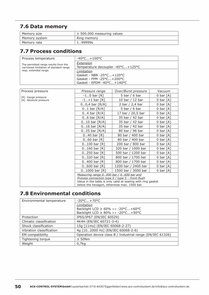
7 .6 Data memoryMemory size ≥ 500.000 measuring valuesMemory system Ring memoryMemory rate 1…99999s
7 .7 Process conditionsProcess temperature
The permitted range results from the narrowest limitation of standard range resp. extended range.
-40°C...+100°CExtensionTemperature decoupler -40°C...+125°CLimitationGasket - NBR -25°C...+120°CGasket - FPM -25°C...+200°CGasket - EPDM -40°C...+140°C
Process pressure
[R] Gauge pressure[A] Absolute pressure
Pressure range Over/Burst pressure Vacuum-1…0 bar [R] 5 bar / 6 bar 0 bar [A]
-1…+1 bar [R] 10 bar / 12 bar 0 bar [A]0…0,4 bar [R/A] 2 bar / 2,4 bar 0 bar [A]0…1 bar [R/A] 5 bar / 6 bar 0 bar [A]0…4 bar [R/A] 17 bar / 20,5 bar 0 bar [A]0…6 bar [R/A] 35 bar / 42 bar 0 bar [A]0…10 bar [R/A] 35 bar / 42 bar 0 bar [A]0…16 bar [R/A] 35 bar / 42 bar 0 bar [A]0…25 bar [R/A] 80 bar / 96 bar 0 bar [A]0…40 bar [R] 80 bar / 400 bar 0 bar [A]0…60 bar [R] 80 bar / 400 bar 0 bar [A]0…100 bar [R] 200 bar / 800 bar 0 bar [A]0…160 bar [R] 320 bar / 1000 bar 0 bar [A]0…250 bar [R] 500 bar / 1200 bar 0 bar [A]0…320 bar [R] 800 bar / 1700 bar 0 bar [A]0…400 bar [R] 800 bar / 1700 bar 0 bar [A]0…600 bar [R] 1200 bar / 2400 bar 0 bar [A]0…1000 bar [R] 1500 bar / 3000 bar 0 bar [A]
Measuring range 0…400 bar / 0…600 bar andProcess connection type 0 / type 5 – front-flushValue in the table is only valid at sealing with ring gasket below the hexagon, otherwise max. 1500 bar.
7 .8 Environmental conditionsEnvironmental temperature -20°C...+70°C
LimitationBacklight LCD ≥ 60% >> -20°C...+60°CBacklight LCD ≥ 80% >> -20°C...+50°C
Protection IP65/IP67 (EN/IEC 60529)Climatic classification 4K4H (EN/IEC 60721-3-4)Shock classification 15g [11ms] (EN/IEC 60068-2-27)Vibration classification 4g [10…2000 Hz] (EN/IEC 60068-2-6)EM compatibility Operation device class B / Industrial range (EN/IEC 61326)Tightening torque ≤ 50NmWeight 0,7kg
ACS-CONTROL-SYSTEM GmbH l Lauterbachstr. 57 l D-84307 Eggenfelden l www.acs-controlsystem.de l [email protected] 51
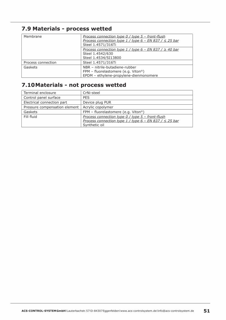
7 .9 Materials - process wettedMembrane Process connection type 0 / type 5 – front-flush
Process connection type 1 / type 6 – EN 837 / ≤ 25 barSteel 1.4571/316TiProcess connection type 1 / type 6 – EN 837 / ≥ 40 barSteel 1.4542/630Steel 1.4534/SI13800
Process connection Steel 1.4571/316TiGaskets NBR – nitrile-butadiene-rubber
FPM – fluorelastomere (e.g. Viton®)EPDM – ethylene-propylene-dienmonomere
7 .10 Materials - not process wettedTerminal enclosure CrNi-steelControl panel surface PESElectrical connection part Device plug PURPressure compensation element Acrylic copolymerGaskets FPM – fluorelastomere (e.g. Viton®)Fill fluid Process connection type 0 / type 5 – front-flush
Process connection type 1 / type 6 – EN 837 / ≤ 25 barSynthetic oil
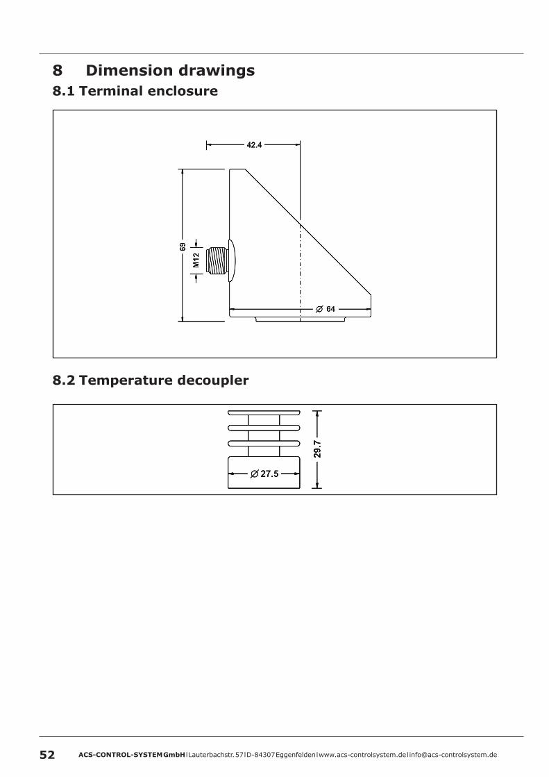
ACS-CONTROL-SYSTEM GmbH l Lauterbachstr. 57 l D-84307 Eggenfelden l www.acs-controlsystem.de l [email protected]
8 Dimension drawings8 .1 Terminal enclosure
8 .2 Temperature decoupler
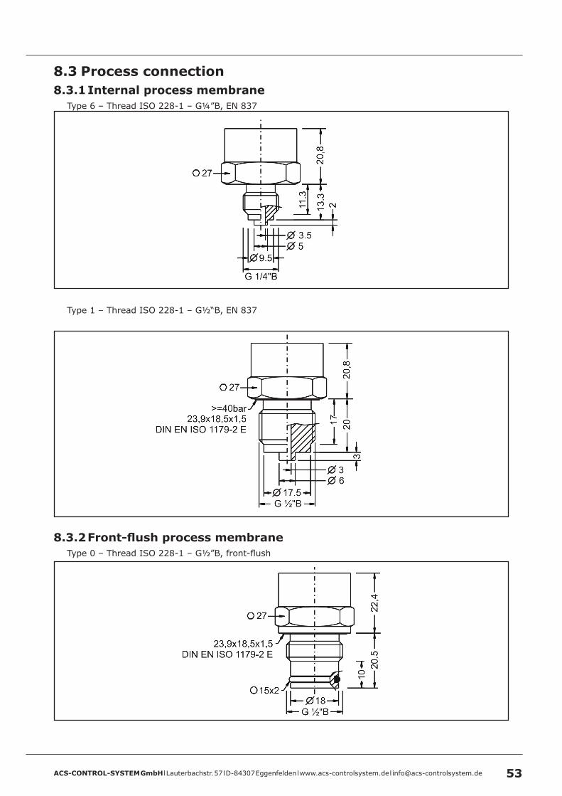
ACS-CONTROL-SYSTEM GmbH l Lauterbachstr. 57 l D-84307 Eggenfelden l www.acs-controlsystem.de l [email protected] 53
8 .3 Process connection8 .3 .1 Internal process membrane
Type 6 – Thread ISO 228-1 – G¼”B, EN 837
Type 1 – Thread ISO 228-1 – G½“B, EN 837
8 .3 .2 Front-flush process membraneType 0 – Thread ISO 228-1 – G½”B, front-flush
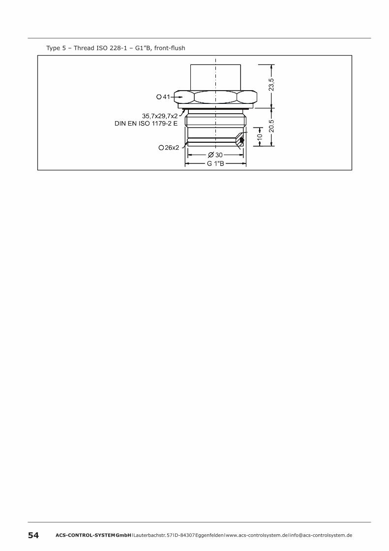
ACS-CONTROL-SYSTEM GmbH l Lauterbachstr. 57 l D-84307 Eggenfelden l www.acs-controlsystem.de l [email protected]
Type 5 – Thread ISO 228-1 – G1”B, front-flush
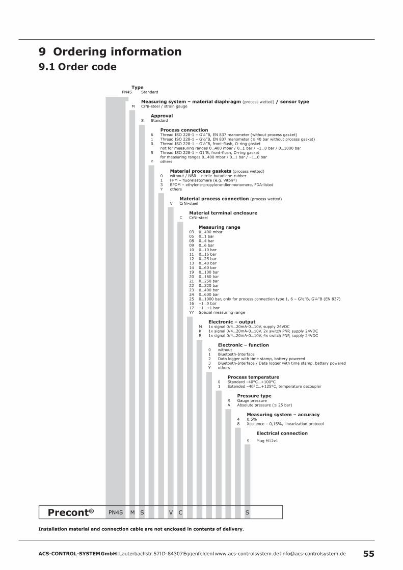
Precont® C SPN4S
ACS-CONTROL-SYSTEM GmbH l Lauterbachstr. 57 l D-84307 Eggenfelden l www.acs-controlsystem.de l [email protected] 55
VM S
Installation material and connection cable are not enclosed in contents of delivery .
TypePN4S Standard
Measuring system – material diaphragm (process wetted) / sensor type M CrNi-steel / strain gauge
Approval S Standard
Process connection 6 Thread ISO 228-1 – G¼”B, EN 837 manometer (without process gasket) 1 Thread ISO 228-1 – G½”B, EN 837 manometer (≥ 40 bar without process gasket) 0 Thread ISO 228-1 – G½”B, front-flush, O-ring gasket not for measuring ranges 0…400 mbar / 0…1 bar / –1…0 bar / 0…1000 bar 5 Thread ISO 228-1 – G1”B, front-flush, O-ring gasket for measuring ranges 0…400 mbar / 0…1 bar / –1…0 bar Y others
Material process gaskets (process wetted) 0 without / NBR – nitrile-butadiene-rubber 1 FPM – fluorelastomere (e.g. Viton®) 3 EPDM – ethylene-propylene-dienmonomere, FDA-listed Y others
Material process connection (process wetted) V CrNi-steel
Material terminal enclosure C CrNi-steel
Measuring range 03 0…400 mbar 05 0…1 bar 08 0…4 bar 09 0…6 bar 10 0…10 bar 11 0…16 bar 12 0…25 bar 13 0…40 bar 14 0…60 bar 19 0…100 bar 20 0…160 bar 21 0…250 bar 22 0…320 bar 23 0…400 bar 24 0…600 bar 25 0…1000 bar, only for process connection type 1, 6 – G½”B, G¼”B (EN 837) 16 –1…0 bar 17 –1…+1 bar YY Special measuring range
Electronic – output M 1x signal 0/4…20mA-0…10V, supply 24VDC K 1x signal 0/4…20mA-0…10V, 2x switch PNP, supply 24VDC R 1x signal 0/4…20mA-0…10V, 4x switch PNP, supply 24VDC
Electronic – function 0 without 1 Bluetooth-Interface 2 Data logger with time stamp, battery powered 3 Bluetooth-Interface / Data logger with time stamp, battery powered Y others
Process temperature 0 Standard –40°C…+100°C 1 Extended –40°C…+125°C, temperature decoupler
Pressure type R Gauge pressure A Absolute pressure (≤ 25 bar)
Measuring system – accuracy 4 0,5%
8 Xcellence – 0,15%, linearization protocol
Electrical connection S Plug M12x1
9 Ordering information9 .1 Order code
ACS-CONTROL-SYSTEM GmbH l Lauterbachstr. 57 l D-84307 Eggenfelden l www.acs-controlsystem.de l [email protected]
9 .2 Additional optionsFor the device additional options are available.The respective abbreviation subsequently follows the order code.
• SF LABS-free, silicone-free / paint compatible version• ML Measurement point designation / TAG – Laser marking• KL Customer label on device – Laser marking• TN Type label neutral• WT Factory certification – drink water suitability• WL Factory certification – food suitability• KF Configuration / Preset• WK Factory calibration – calibration certificate
9 .3 AccessoriesAccessories are not content of delivery of the device and must be ordered separately.
9 .3 .1 Installation materialA wide range of accessories for device installation is constantly available, e.g.• Welding sockets• Welding flanges• Blind flanges• Flanges with thread• Reductions• Tube nuts• Siphons• Marking plate measuring point, laser marked• etc.
9 .3 .2 Connection cable / Cable boxConnection cable M12x1, material PUR, shielded• LKZ04##PUR-AS 4-pole, straight, ## = length 2…30m• LKW04##PUR-AS 4-pole, angled, ## = length 2…30m• LKZ05##PUR-AS 5-pole, straight, ## = length 2…30m• LKW05##PUR-AS 5-pole, angled, ## = length 2…30m• LKZ08##PUR-AS 8-pole, straight, ## = length 2…30m• LKW08##PUR-AS 8-pole, angled, ## = length 2…30m
Other connection cables, e.g. other material, unshielded or integrated LED are available.
Cable box M12x1• BKZ0412-VA 4-pole• BKZ0512-VA 5-pole• BKZ0812-VA 8-pole

ACS-CONTROL-SYSTEM GmbH l Lauterbachstr. 57 l D-84307 Eggenfelden l www.acs-controlsystem.de l [email protected] 57